US6009369A - Voltage monitoring glow plug controller - Google Patents
Voltage monitoring glow plug controllerDownload PDFInfo
- Publication number
- US6009369A US6009369AUS08/931,470US93147097AUS6009369AUS 6009369 AUS6009369 AUS 6009369AUS 93147097 AUS93147097 AUS 93147097AUS 6009369 AUS6009369 AUS 6009369A
- Authority
- US
- United States
- Prior art keywords
- glow plug
- engine
- glow
- preglow
- controller
- Prior art date
- Legal status (The legal status is an assumption and is not a legal conclusion. Google has not performed a legal analysis and makes no representation as to the accuracy of the status listed.)
- Expired - Lifetime
Links
Images


Classifications
- F—MECHANICAL ENGINEERING; LIGHTING; HEATING; WEAPONS; BLASTING
- F02—COMBUSTION ENGINES; HOT-GAS OR COMBUSTION-PRODUCT ENGINE PLANTS
- F02P—IGNITION, OTHER THAN COMPRESSION IGNITION, FOR INTERNAL-COMBUSTION ENGINES; TESTING OF IGNITION TIMING IN COMPRESSION-IGNITION ENGINES
- F02P19/00—Incandescent ignition, e.g. during starting of internal combustion engines; Combination of incandescent and spark ignition
- F02P19/02—Incandescent ignition, e.g. during starting of internal combustion engines; Combination of incandescent and spark ignition electric, e.g. layout of circuits of apparatus having glowing plugs
- F02P19/026—Glow plug actuation during engine operation
Definitions
- the present inventionconcerns a glow plug controller for use in activating diesel engine glow plugs with a signal to control power to warm the glow plugs prior to initiating combustion and for maintaining a signal to control power that continues to warm the glow plugs after combustion has been initiated.
- Diesel enginesare substantially different from the standard 4 or 2 cycle, sparked ignition internal combusion engines.
- the diesel enginedoes not have a sparking device such as a standard spark plug. Fuel is ignited when fuel and hot compressed air are mixed in the engine cylinder(s). For this ignition to occur efficiently, the engine must be brought to a temperature at or above a given minimum operating temperature, i.e. a cold diesel engine will not achieve ignition and run efficiently.
- a preferred method for heating a diesel engine prior to initial startupis to use electric "glow plug” heaters. These heaters serve to bring the diesel engine up to an efficient operating temperature before the engine is started. Ideally glow plug heaters will rapidly bring a diesel engine up to a desired starting temperature in a "pre-glow” period. After the engine has started, the glow plugs will go into an "after glow” period where they will operate sufficiently long to maintain desired engine temperature until engine self-heating reaches an efficient sustain point. The glowplugs also enable the engine to run smoothly during an initial idle and minimize emission of white smoke due to incompletely burned fuel. Once an engine can sustain its operating temperature, the glow plug is turned off.
- U.S. Pat. No. 4,882,370 to Arnold et alshows a solid state microprocessor controlled device for regulating certain aspects of glow plug performance.
- the Arnold circuitryadjusts the duty cycle of glow plugs as a function of temperature, regulates preglow function, and detects undesirable short circuits and open circuits for implementing a disable function.
- U.S. Pat. No. 4,300,491, to Hara et al.achieves a variable time control of the preglow period by means of a plurality of transistors and diodes.
- Van Ostrom, U.S. Pat. No. 4,137,885describes means for cyclicly interrupting a glow plug energizing circuit when a maximum temperature is reached.
- CooperU.S. Pat. No. 4,312,307 describes circuitry for control of the duty cycle of glow plugs by means of heat-sensitive switches.
- a glow plug controller constructed in accordance with the present inventioncontrols operation of a diesel engine that provides motive power to a motor vehicle.
- An electric power source mounted to the motor vehicleprovides a voltage signal.
- a glow plug controller circuitis powered by the power source.
- a voltage source monitoris coupled to the glow plug controller for providing a signal indicative of power applied to the one or more glow plugs.
- a switching device coupled to the glow plug controller and the electric power sourceenergizes the one or more glow plugs for a controlled time duration prior to initiating combusion in the diesel engine.
- the glow plug controllerincludes an adaptive control program for adjusting at least the time duration prior to combustion of the one or more glow plugs based on the power delivered to the glow plugs.
- a preferred embodiment of the inventionis accomplished using a microprocessor.
- a microprocessoras a preferred control circuit enables self adaptive control based upon sensor and electrical inputs of variables such as: battery voltage, glow plug voltages, glow plug currents, engine temperature.
- Such controlalso achieves sophisticated diagnostics and reprogrammability (as, for example, at various service increments of specified numbers of hours and/or miles of engine life with anticipated subsequent loss of engine compression) as well as precise unit to unit repeatability.
- Such algorithmscan correct for sensor hysteresis and time lag, ambient air temperature, ambient air density, ambient air humidity, intake mass air flow, exhaust gas composition, exhaust gas temperature, alternator output, engine speed, engine torque, engine power, accelerator throttle position, fuel consumption, engine compression, engine mileage, engine operational hours, fuel type and the like to affect an on and off cycling control using open loop control and/or closed loop feedback control of glow plug voltage and/or current to maintain glow plugs more closely within an optimal temperature range specific to needs based upon engine system operational conditions.
- Microprocessors as controllersshow improvements over some non-digital components and elements which can often exhibit performance characteristic variations based upon temperature, time and applied voltage.
- Engine temperaturecan typically be determined by various sensing devices of types including, but not limited to: Thermistors, positive temperature coefficient resistor, negative temperature coefficient resistor, resistance temperature device, temperature sensing diode, integrated circuit sensor, bimetal device, and gas pressure bulb.
- Algorithms and/or circuitry within the control modulecan give predictive correction to actual cylinder temperature based upon the known and/or actively determined hysterical and time lag nature of various types of locations of temperature sensors.
- Glow plug voltageis relatively simple to measure directly from the power relay terminal connected to the glow plug(s).
- Glow plug currentcan be determined by conducting it through a low value series resistor and determining the voltage drop as being proportionately linear with the current.
- This series resistorcan be configured as an inductor having a ferromagnetic core of various choices of geometry and with an inverse parallel freewheeling diode such that it will have a characteristic RL electrical rise time such that its current levels will be significantly lower than for a resistive glow plug alone during the time of mechanical contact bounce of the power relay.
- reliability of the relay contactscan be enhanced by reduction of high current contact bounce.
- each glow plugcan be also applied directly to a heater element thermally integral with a bimetallic-type switch being also thermally integral with the diesel engine such that the bimetal switch in astable operation will have closed time to enable glow plug relay energization thus affecting functional intrinsic regulation of glow plugs on times based upon both engine temperature and upon applied glow plug voltage.
- the electrical current passing through a glow plugcan also pass in series through a conceptually similar bimetallic switch heater, although being designed as a lower resistance value and for higher current than a voltage driven heater, thus a measure of functional electrical short glow plug current limitation is imparted such that the glow plug short circuit on time would be significantly reduced relative to the method whereby only the glow plug voltage is sensed.
- An optional variant on this conceptis to have two heaters on the bimetallic switch such that one is energized by glow plug voltage and the other energized by glow plug current.
- Another optional variant on this conceptis to have one or more heaters on the bimetallic switch such that the heaters are provided with functional drive signals representative of glow plug voltage and/or current and/or calculated power such that the heater energization results in appropriately engineered astable glow plug relay operation. Sensing of both voltage and/or current can be used to affect wider ranging functional control over normal and abnormal glow plug operating characteristics.
- the informationcan be determined from the above inputs and sensors for control of appropriate engine glow plug operation is of two basic types--the necessary versus the actual glow plug heat and temperature for engine operating conditions.
- Analog signal and sensor informationcan be converted into digital information by separate interface circuitry or by an analog-to-digital converter (integral with some digital microprocessors) for computational processing in the digital control algorithm. It is possible, although less likely to be commercially produced due to cost and performance factors, that digital signals can also be converted into analog signals for processing and/or reprocessing by analog and/or digital circuitry.
- Determination of actual glow plug temperatures for interactive adaptation of glow plug energization timing controlcan be performed by circuitry which can monitor glow plug resistance typically during off times by one of various methods including: Voltage drop for a fixed current, current for a fixed voltage, voltage in a resistive voltage divider, time based decay with capactitive source, and alternatively by an integral platinum resistance temperature device. These methods make use of the fact that many resistors have some temperature coefficient of resistance such that the absolute resistance and/or relative resistance changing with temperature and time can be determined in precise manner. Glow plug resistance can be monitored and correlated with glow plug temperature and also with engine temperature for adaptive control of glow plug energization times to reduce excessive glow plug temperatures and also to reduce insufficient glow plug heat and temperatures for improved engine starting and warm up.
- One resistance determination circuitrather than multiple dedicated resistance determination circuits, can be switched among numerous glow plugs to determine their resistance characteristics.
- the glow plug controllercan modify the operation of the glow plugs in response to functional algorithms based upon various inputs from potentially diverse digital and/or analog sources. Based upon functional information of integrated engine operational time, temperature, and/or loading the glow plug controller can compensate for engine wear and subsequent reduction in compression ratio by increasing the preglow heating time and afterglow heating times for improved starting and warmup.
- Engine wear and compression losscan be compensated for by the microprocessor via various methods including: Self reprogramming based upon monitored engine operational parameters, manual reporgramming the microcomputer at specified service mileages and/or times, manual reprogramming and entering of measured compression readings for each cylinder at various service mileages and/or dates, and manual clipping of jumper wires and/or setting of switches on the printed circuit board based upon mileage and/or compression.
- Lower air density, lower air pressure, and/or lower battery voltagecan be compensated for by the controller by increasing preglow time, increasing afterglow on time duty cycle, and increasing afterglow cycle period for increase in glow plug heat and temperature sufficient to improve engine starting
- MUXsystem multiplex
- DEMUXdemultiplex
- datais periodically broadcast onto the MUX system
- datais broadcast irregularly to the MUX system
- datais broadcast only when polled or requested.
- the thermal time constants involved for glow plug heating and coolingare on the order of several seconds, which is orders of magnitude of the typical times required for a polling and receiving of MUX bus information from remote nodes, therefore a MUX system is generally suitable in terms of timing capability for collecting various inputs from diverse locations and for outputting signals to the power switching relays to perform all of the functions described herein.
- Improved functions of the glow plug controllercan be implemented via separate modules interconnected and communicating via system MUX node and/or dedicated wiring for incorporating additional input and output functions, features, and capabilities such that system inputs, functional algorithm processing control, and power switching output as discrete modules are not necessarily physically integral or even proximal.
- a desired functionincorporates a memory circuit to disable preglow heating if the engine run switch when switched from off to run has been in the switch off position for less than three minutes after previous running or preglow heating. This disables the circumstances where a human operator activates the run switch off and on repeatedly causing fixed preglow heating times to be repeated in close succession, resulting in possible overheating of the glow plugs.
- An optional function for potential incorporation into the glow plug controlleris a variable delay until the alternator is at a sufficiently safe and low speed and thus low output, as determined from the frequency component of the alternator R-tap connection, to deenergize the glow plugs after the ignition switch is changed from the run to the off position during the afterglow 2 cycle on time thus reducing the potentially damaging and dangerous voltage spike generated by instantaneous discontinuation of high glow plug current through the inductive coils of the alternator.
- the need for thisis because the battery connection to the alternator is typically dropped out immediately when the switch is changed from the run position to the stop position and the integral voltage regulator within the alternator maintains alternator field current such that the alternator can continue output load current therefore switching off of the high glow plug current when sourced solely from and through the inductive alternator is likely to cause a much higher voltage spike and much more energetic relay contact arc than when switching of this high current when sourced solely from or in parallel with the electrochemical storage battery which acts as a voltage limiting sink for the energy spike.
- the energy stored in an inductoris equal to (1/2)(inductance)(square of current), inductance being measured in units of Henry, current being measured in units of Ampere, energy being expressed in units of Joule.
- Another optional functional featureis the use of more than one power relay, contactor, or solid state switch for switching power on and off to individual glow plugs or groups of glow plugs, ideally, at least one switch device for each glow plug.
- Switching power to each glow plugindependently allows for practical application of multiple solid state switches rated for currents in the 20 to 30 Amp range having additional benefits of: Small size, lightweight, audibly quiet, an order of magnitude increase in number of switch cycles per life, reliability, no contact bounce, and no contact bounce associated conducted and/or field emissions.
- Multiple switchesallow improved output control of each individual glow plug or group including such functions as: Independent timing, independent disabling due to excessive short circuit condition, and dependent switching on and off individual glow plugs or groups at differing times for reduction of switching transients and dump spike magnitudes.
- Use of individual switching for each glow plugcan allow completely independent and individual fixed and/or varying switch control timing functions of preglow time, afterglow times, afterglow cycle on times, afterglow duty cycle, afterglow cycle periods, and the like for each glow plug based upon its actual operating conditions including inputs of and/or calculated values for: Voltage, current, power, resistance, temperature, engine age, associated cylinder compression ratio, ambient air conditions, and the like.
- the glow plug controllercan incorporate additional features such as shielding, transient protection, and filtration of electrical noise over wide ranging frequencies (including zero Hz) and of interference types including: Conducted transients, electrostatic discharge, load dump, reverse voltage, magnetic fields, electric fields, and electromagnetic fields. Due to the sensitive and high frequency electronics within the control module and in cases of integral control and power switching within the same control module, it may be necessary to include shielding and/or filtration for protection of: Module components from each other, module components from outside sources of noise, and outside components from noise produced within the module. Additional concepts include additional interface communication and control features allowing service monitoring of historical and present operation plus modification control of glow plug functional algorithm control parameters.
- One embodiment of the inventionhas application with heavy-duty military vehicles such as trucks, infantry fighting vehicles, tanks, and others. Because such vehicles are typically operated by a large number of operators having different skill levels, considerable warning and protection equipment is incorporated into such vehicles.
- This warning and protection equipmentincludes means for informing an operator of the operations and conditions of the vehicle.
- Heavy-duty vehicles of this natureinclude switching mechanisms for selectively disconnecting all or a part of the electrical loads from a battery which is used to provide electrical power for the vehicle. This function is sometimes called "load dumping.”
- the load dumpingis controlled by electronics which senses engine shut-off and commands a solenoid to drop out the vehicle loads after the conditions of ignition switch-off and commands a solenoid to drop out the vehicle loads after the conditions of ignition switch off and engine speed is below 100 RPM's are coincidentally met. Further details of one such system are disclosed in U.S. Pat. No. 5,287,831 to Andersen et al. The disclosure of this patent is incorporated herein by reference.
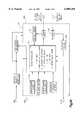
- FIG. 1Ais a partially schematic, partially block diagram illustrating some of the electrical components of a diesel engine and associated peripheral equipment which form the environment for the present invention
- FIG. 1Bis a block diagram of a microprocessor controlled glow plug controller for activating a glowplug
- FIGS. 2A and 2Bare detailed schematics that disclose details of the FIG. 1B controller
- FIGS. 3-5are flowcharts of a diesel engine modification routine that is used to modify operation of the engine based upon sensed conditions;
- FIG. 6is an energization sequence of preglow and afterglow periods
- FIG. 7is a block diagram showing interconnection between a glow plug relay and a indicator lamp relay.
- FIG. 8is a block diagram of a controller circuit that implements an electrical engine starting system having load dump control circuitry, reverse voltage protection, frequency controlled circuity and filtration.
- FIG. 1AToward the left-hand portion of FIG. 1A is a column of eight glow plugs, the uppermost of which is indicated by the reference character G. Operation of the glow plugs is governed by a glow plug controller 10.
- An electric starter motor MWith associated switching, is provided for starting the engine.
- Batteries Bare provided for selectively actuating the starter motor M, and for providing DC electrical power for operating other electrical components of the vehicle and for peripheral components of the engine as needed.
- the two series connected vehicle batteries Bprovide 24 volts DC.
- a run/start switch RSis provided for actuating the vehicle ignition circuitry and for selectively actuating the starter.
- An alternator Adriven by the engine, provides electrical power for charging the batteries B and for providing electrical power to the vehicles loads.
- the alternator Ahas an "R tap,” (connected to the field) indicated by reference character R.
- a fuel solenoid Fgoverns flow of fuel to the engine.
- a clutch control Celectrically engages and disengages an electric motor driven engine cooling fan.
- a wait-to-start lamp Wprovides a visual indication to an operator when the preglow cycle is occurring and it would thus be inappropriate to try to start the diesel engine.
- a brake warning lamp BWindicates to the operator when a parking brake is set. The brake warning lamp BW also indicates when the start solenoid is engaged.
- a brake pressure switch BPprovides an indication to the operator when a pre-determined amount of force is applied to the service brake pedal.
- a park brake switch PBindicates by means of the lamp that the vehicle parking brake is set.
- the electrical system of the engineoperates several types of electrical loads.
- One such loadis a heater motor indicated generally at the reference character H.
- Lighting loadsare connected to a lead generally indicated by the reference character LL.
- Certain miscellaneous electrical vehicle loadsare indicated by the resistor at reference character VL.
- the present inventionincludes improved circuitry and sub-circuits for governing and safe-guarding operation of the known components illustrated in FIG. 1A.
- Interfaces for connecting the known components of FIG. 1Aare provided by an engine connector C1 and a body connector C2, both illustrated in FIG. 1A. These connectors interface between the glowplug controller 10 and the engine and vehicle components shown in FIG. 1A.
- FIG. 1Bis an overview of the control functions performed by a microprocessor operated glowplug controller 10 used to control a time duration of glow plug activation for a diesel engine having one or more glow plugs.
- a microprocessor 12forms part of a glow plug controller as do a number of condition monitoring circuits for using to control engine glow plug energization.
- the microprocessoris used for inputting digital and analog signals from sensors and other inputs, digitizing the inputs as required, signal processing in accordance with a control program and outputting signals to control glow plug function.
- the controller 10latches a power input from the ignition and reads the engine temperature from a temperature sensor 14 (FIG. 2B) located in close proximity to a housing which encloses the controller.
- the temperature sensor 14includes a thermistor 16 and resistor 18. Temperatue is read at the junction 19 between the thermistor and the resistor and coupled to pin RA0 of the microprocessor 12. Internally within the microprocessor, the input signal from the junction 19 is converted from an analog input to a digital signal for subsequent signal processing.
- a battery voltage sensing circuit 20is coupled to the microprocessor 12 at pin RA1. Voltage is sensed at a junction 22 (FIG. 2A) between two resistors 24, 26 with a capacitor 28 being a noise filtering capacitor. Internally within the microprocessor, the input signal from the junction 22 is converted from an analog input to a digital signal for subsequent signal processing.
- the preglow periodincludes an off period during which the microprocessor monitors an alternator signal indicating the vehicle operator has initiated engine operation and diesel combusion has begun. Mere cranking of the engine is not enough to cause a sensing of this signal.
- the afterglow period of FIG. 6begins with application of the signal to the microprocessor within the off period of the preglow. If the specified input from the alternator is not received within the specified off period of the preglow, the controller cycle ends and no afterglow occurs.
- a power supply circuit 50includes a diode 51 coupled to a battery input 52 and an integrated circuit low voltage drop regulator 53 that produces a five volt output signal Vcc.
- the diode 51provides reverse polarity protection.
- a resistor 54is a current limiting resistor for the five volt regulator 53.
- Two resistors 55, 56form a voltage divider setting the reference feedback voltage to the three terminal regulator.
- the regulatoris a part number TL431 MPK regulator.
- a capacitor 57filters the Vcc voltage by storing charge.
- a resistor 58draws enough current from the node Vcc to keep the three terminal voltage regulator integrated circuit 53 within its range of operating current and also allows the power supply cirucit 50 to discharge rapidly to implement a power up reset function and a capacitor preglow memory function.
- a capacitor 59 coupled to a Vdd input to the controller 12allows the controller to continue to operate for a period after the power input Vcc goes low as the ignition is turned off.
- Two resistors 60, 62are coupled between the five volt regulated signal Vcc and ground.
- the voltage at a junction between the resistors 60, 62is coupled to the microprocessor and provides a temperature shutdown reference signal at the microprocessor input 64 at port RA2. This voltage signal allows the microprocessor 12 to compare with an internal signal for safe protective shutdown in the case of excessive internal microprocessor temperature.
- the value of the resistor 60is selected from a chart based upon the desired shutdown.
- the microprocessor 12operates from the Vcc signal from the power supply circuit 50.
- the Vcc signalis coupled to the microprocessor 12 through a pull-up resistor 65.
- a resistor 66is provided as a pulldown to ground for microprocessor pin RB1.
- a clock oscillator 67resonates at 4 Megahertz.
- a resistor 72 and a diode 74provide a circuit path to charge a capacitor 70 in parallel with a resistor 71.
- the voltage on the capacitor 70is coupled to a comparator 76.
- a second input to the comparator 76is a reference voltage of 0.5 volts derived from the regulated signal Vcc. If the capacitor 70 has a voltage above 0.5 volts at power up, the ignition switch has been switched to the run positon within the previous three minutes. In this event a preglow time is disabled.
- the output of the comparator 76is pulled up to Vcc by a resistor 78 and is input to the microprocessor 12 at pin RA3. If the capacitor 70 has a voltage below 0.5 volts at power up, this causes the comparator 70 to go low resulting in a zero on the pin RA3 and the microprocessor will then enable the preglow time.
- An alternator input 80provides a signal from the RTAP of the alternator and provides an alternating signal having a frequency component which indicates the relative operating speed of the alternator and thus the engine.
- the signal at the input 80is rectified by a diode 82 and filtered by a resistor 84 and capacitor 86 and then supplied to the microprocessor 12 at input pin RB0.
- the microprocessor 12reads a DC signal indicative of an engine running condition.
- the voltage level at the input 80is also stepped down by a voltage divider having two resistors 88, 89 and a capacitor 90 and coupled to pin RB2 of the microprocessor 12 and is used during diagnostic testing of the circuits.
- the input 80is sensed upon powerup of the controller it means that the user started the engine without allowing a preglow. Under these circumstances the controller does not provide any glow plug energization.
- the input 80also affects glow plug energization if the engine has been running (as sensed at the input 80) within three minutes of receipt of an ignition input that powers up the microprocessor. If the ignition key is cycled quickly an after-glow cycle is allowed but a pre-glow period is not until 3 minutes has elapsed of an ignition off period. This inhibit function prevents overheating and damage to the glow plugs.
- the circuit of FIG. 7also includes a relay 111 for controlling an energization state of the wait to start lamp W.
- Some motor vehicle manufacturersprovide an equivilant circuit to that shown in FIG. 7 that is coupled to the controller 10 by means of the connectors C1, C2.
- the circuit of FIG. 7produces a transient protected output 112 from the controller that goes high when the ignition input from the switch RS goes high.
- the wait to start lamp Wis also coupled to the ignition signal and so long as the relay coil 113 is de-energized, the coil contacts 114 are closed to activate the lamp W.
- a relay output 116goes high to energize a coil 117 and activate the glowplugs. This occurs upon receipt of the ignition input. After the pre-glow "on" state of table 1 the output 116 goes low to energize the relay coil 113 and extinquish the lamp W.
- the circuit 120(FIG. 2B) includes two resistors 121, 122 that are coupled to a microprocessor output 123 at pin RB3 and having a junction 124 coupled to a base input 125 of a switching NPN transistor 126 whose conductive state is controlled by the output 123.
- a zener diode 131that protects the collector junction 130 as well as a gate input 132 of a MOSFET transistor 133.
- Two resistors 134, 135 coupled between the collector junction 130 and the MOSFET gate inputact as biasing transistors for the gate 132 of the MOSFET transistor 133 which is driven by the switching transistor 126 or by an open collector pulldown output of a comparator 138.
- Over current protectionis provided for the transistor 133 by an over current protection circuit 140.
- a resistor 141is a shunt resistor which detects over-current in the relay that activates the glowplugs.
- the resistors 142, 143 and a capacitor 144act as biasing resistors and providing filtering for a switching transistor 145.
- the transistor 145will turn on as the voltage across the resistor 141 exceeds 0.6 volts.
- the resistors 146, 147 and capacitor 148are filtering devices to interface with the microprocessor 12. If the current through the resistor 141 becomes excessive, the transistor 145 turns on and turns off the FET 133.
- a pulse circuit 150Unless disabled by a sensed temperature of greater than 50 degrees Celsius, a pulse circuit 150 immediately initiates energization of the relay drive transistor 133 with a pulse upon power up before the approximately 100 milliseconds it takes for the microprocessor 12 to power up and take over functional control.
- This initial power up functionis controlled by circuit inputs 151, 152 to a comparator 154 having an output coupled via the comparator 138 to the collector junction of the switching transistor 126.
- Sensed temperatures above 50 degrees Celsuiswill disable the immediate application of power to the glow plug relay. This disabling is performed by a voltage divider coupled to the power supply output Vcc that is made up of a thermistor 164 and resistor 165 and filtered for noise by a capacitor 166 as the non-inverting input 151 to the comparator.
- a 50 degrees Celsius reference signal at its inverting input 152comes from a voltage divider 168 formed by the combination of three resistors.
- the output of the comparator 154is open collector when off and will therefore allow a resistor 169 to pull up the non-inverting input of the comparator 138 via a diode 170 unless a sensed temperature of greater than 50 degress pulls the anode of the diode low.
- glow plug controller 10which controls glow plug operation as a function of engine temperature and sensed battery voltage.
- the present inventionalso relates to controlling glow plug operation as a function of other parameters related to a status of engine operation or characteristics, can be used as well by a microprocessor controlled glow plug controller to influence glow plug operation.
- engine cylinder compressionin addition to power applied to the glowplugs, can be used as an input to regulate glow plug operation.
- a compression sensoris used to provide an input to the microprocessor digital logic circuitry.
- the digital logic circuitryresponds to the compression sensor information to increase glow plug heating as engine compression decreases.
- FIGS. 3 and 4constitute a flow chart describing the manner in which digital logic circuitry, such as a microprocessor is programmed in order to govern glow plug operation as a function of engine temperature and engine compression.
- the steps shown in FIG. 3begin with retrieving 200 the average “Cold Engine” average compression "Cp".
- Cpis as computed and stored in a previous cycle of operation or is a factory set default on the first cycle of operation after a reset.
- a "look up” table or stored algorithmis then used to compute 202 a desired glow plug temperature “Td” for engine starting.
- a suitable "look up” table or algorithmcould be readily determined from empirical studies of engines spanning a range of “Cold Engine” compression values.
- an "Engine Ready” indicationis given 210.
- This indicationcan be a light, audible tone, both or other means to indicate to the operator that the engine is ready to be started.
- the controllerthen monitors 212 the engine to determine when it actually starts.
- a common means to detect engine startis to monitor the voltage from the alternator (not shown).
- the controllerbegins a timer 214 (t1). During the first few cycles of operation after engine start, the engine compression is read 216 and a “Cold Engine” average compression “Cp” is computed 218. During the first “n” cycles of operation after engine start, the engine compression is read 216 and a “warm Engine” average compression “Ca” is computed 220. Once a “Cp” and a “Ca” have been computed they are stored 222 where they will be available for retrieval the next engine starting sequence.
- the previous "Ca” and a predetermined maximum time “tmax”are retrieved 224.
- "Ca”is then used to compute a desired glow plug operating temperature “Ta” at step 224.
- an empirically determined “look up” table or algorithmcan be used to compute "Ta”.
- the time “t2”is then measured 226 and the difference "t2-t1” is compared to "tmax” at step 228. If the difference exceeds "tmax”, the controller is stopped 230 and power to the glow plug(s) is discontinued. If the difference does not exceed "tmax”, the glow plug temperature "T” is read 232 and compared to the desired operating temperature "Ta” 234.
- step 236is skipped and control is transferred back to step 226 where the process can repeat until step 230 is reached.
- the present inventioncontrols glow plug operation as a function of ambient barometric pressure.
- Barometric pressure sensorsare well known in the art, and, for that reason, will not be described in detail here. Suffice it to say that a barometric pressure sensor is used to provide an analog input to the glow plug controller whose value is a function of barometric pressure.
- the analog barometric pressure indicating signalis digitized in known fashion, as disclosed above in connection with the engine temperature signal, and then can be processed by the digital logic circuitry, such as a microprocessor, and the output of the microprocessor reconverted to analog form and used to control glow plug operation. As barometric pressure is reduced, the air with which fuel is mixed becomes less dense.
- the present embodimentresponds to a decrease in barometric pressure to increase glow plug heating.
- the increase in glow plug heatingis done by lengthening the time period of pre-glow or after-glow, or by increasing the duty cycle of operation of the glow plugs.
- FIG. 4shows method steps 240-268 a flow chart for use in programming digital logic circuitry for increasing glow plug heating operation as a function of decreasing barometric pressure.
- the barometric pressureis read 240 prior to engine startup.
- a "look up” table or algorithmis then used to compute 242 desired glow plug temperatures "Tp" & "Ta".
- Tpis the desired temperature prior to starting and "Ta” is the desired temperature after engine start.
- the "look up” tables or algorithmcan be readily determined by empirical means by studying engine starting and running characteristics over a range of barometric pressures. For instance, the "Tp" required to start an engine at an elevation of 5,000 feet could be expected to be higher than that required at sea level.
- the glow plug temperature "T”is read 244 and then compared to "Tp" at step 246. If “T” ⁇ "Tp”, the Glow Plug is then powered 248 and steps 244, 246, 248 are repeated until “T” is greater or equal to "Tp”. Once "T” reaches "Tp”, an "Engine Ready” indication is given 250. This indication can be a light, audible tone, both or other means to indicate to the operator that the engine is ready to be started. In some applications it may be desirable to have the controller initiate an engine start at step 250 instead of merely providing an indication of engine status.
- the controllernext monitors 252 the engine to determine when it actually starts.
- a common means to detect engine startis to monitor the voltage from the alternator (not shown). Once the engine start has been detected, the controller retrieves 254 a maximum time value "tmax” and begins a timer (t1) at step 256. The time “t2" is then read at step 258 and "t2-t1” is compared to "tmax” at step 260. If “t2-t1” exceeds “tmax”, the process is stopped 262. If “t2-t1” does not exceed "tmax”, the glow plug temperature "T” is then read 264 and compared 266 to the desired temperature "Ta”".
- step 268If “T” is less then “Ta”, power is applied to the Glow Plug(s) at step 268 and steps 258, 260, 264, 266 are repeated.
- step 268is bypassed (the Glow Plug(s) are not powered) and steps 258-266 are repeated until step 262 is reached, i.e., "t2-t1" >"tmax".
- an exhaust sensoris provided.
- the exhaust sensorproduces an analog signal whose value is a function of the presence of a particular sensed component or components of engine exhaust.
- the present embodimentadjusts glow plug operation as a function of the amount of one or more of the particular sensed exhaust components.
- exhaust sensorsare well known in the art. Such sensors can detect the presence of various exhaust components. Detection of exhaust components give rise to information relating to the degree of completeness of combustion of the fuel in the engine cylinders. The presence of smoke, resulting from particulate matter, usually indicates incomplete combustion. So does a relatively high fraction of oxygen in the exhaust.
- oxygen exhaust sensorsare well known in the art. Such a sensor is used to provide an analog signal whose value indicates the amount of sensed oxygen in the exhaust. This value is digitized for subsequent handling by the digital logic circuitry. After processing by the digital logic circuitry, the digital logic circuitry produces an output for governing glow plug operation. That output is reconverted to analog form and used to control the glow plug.
- the amount of glow plug heatingis increased in response to the increased sensing of exhaust components which result from incomplete combustion. Accordingly, as sensed oxygen rises, the glow plug controller adjusts the glow plugs to provide additional heating.
- the amount of additional glow plug heatingis a function of the amount of oxygen sensed in the exhaust during the last previous period of operation.
- a non-volatile memoryis provided for storing the output of the exhaust sensor. The memory saves the stored value until the engine is restarted, at which time it adjusts glow plug operation as a function of the stored data representing earlier exhaust component information.
- FIG. 5is a flow chart setting forth the manner of programming the digital logic circuitry in order to accomplish the function of this particular embodiment.
- the method of programmingis virtually identical to that of FIG. 4, except that a different variable is being sensed.
- step 270The steps shown in FIG. 5 begin with retrieving the average exhaust oxygen "Ep" (step 270).
- "Ep”is as computed and stored in a previous cycle of operation or is a factory set default on the first cycle of operation or after a reset.
- a "look up” table or stored algorithmis then used to compute a desired temperature “Td” for engine starting in step 272.
- a suitable "look up” table or algorithmcould be readily determined from empirical studies of oxygen emissions from starting engines spanning a range of “Cold Engine” starting temperatures.
- Steps 274 through 278are then repeated until "T” equals or exceeds "Td".
- an "Engine Ready” indicationis given in step 280.
- This indicationcan be a light, audible tone, both or other means to indicate to the operator that the engine is ready to be started.
- the controllerthen monitors the engine to determine when it actually starts (step 282).
- a common means to detect engine startis to monitor the voltage from the alternator (not shown). Once the engine start has been detected, the controller begins a timer at step 284(t1).
- the exhaust oxygenis read (step 286) and a "Cold Engine” average exhaust oxygen “Ep” is computed (step 288).
- the exhaust oxygenis read (step 286) and a "Warm Engine” average exhaust oxygen “Ea” is computed at step 290.
- an "Ep” and an “Ea”have been computed, they are stored at step 292 where they will be available for retrieval during the next engine starting sequence. Concurrent with initiation of steps 286-292, the previous "Ea” and a predetermined maximum time “tmax” are retrieved at step 294. "Ea” is then used to compute a desired engine operating temperature "Ta” at step 294.
- “Ea”is then used to compute a desired engine operating temperature “Ta” at step 294.
- an empirically determined “look up” table or algorithmcan be used to compute “Ta”.
- the time “t2”is then measured at step 298 and the difference "t2-t1" is compared to "tmax” at step 300. If the difference exceeds "tmax”, the controller is stopped (step 302) and power to the glow plug(s) is discontinued. If the difference does not exceed "tmax”, the glow plug temperature "T” is read at step 306 and compared to the desired operating temperature “Ta” at step 304. If “T" ⁇ "Ta”, power is applied to the glow plus(s) at step 308 and steps 296-308 are repeated. If “T” equals or exceeds "Ta”, step 308 is skipped and control is transferred back to step 296 where the process can repeat until step 302 is reached.
- ECMengine control module
- sensorssuch as a barometric pressure sensor that are used in glow plug control algorithms such as that in FIG. 4.
- a single data connection to the ECMis used to eliminate the additional signal lines and/or sensors that would be required for the controller to obtain these values.
- FIG. 8depicts an electrical engine starting system 320 that provides protection for a starter system of a vehicle having an internal combustion diesel engine.
- a controller 322controls a wait to start lamp and energizes a glowplug solenoid 324 in response to sensed conditions.
- the wait-to-start lamp and associated comparator and latching circuitryis provided for actuating the wait lamp in response to initiation of a glow plug controller pre-glow operation, and for subsequently extinguishing the lamp. Once extinguished, the lamp cannot be re-actuated until and unless the ignition has been toggled.
- the system 320includes a field effect transistor for controlling glow plug controller operation by means of an auxilary solenoid.
- Load dump control circuitry 330responds to frequency to voltage conversion to inhibit disconnection of electrical loads from a engine driven alternator input 332 even when the motor vehicle ignition is turned off until engine speed has dropped to a safe level. This prevents voltage spikes which could otherwise result from a sudden unloading of the alternator, a phenomenon which could damage a voltage regulator or other electrical circuitry.
- the controller 322also controls or maintains an afterglow operation subsequent to engine combustion.
- a programmable logic deviceis a well known type of digital logic circuit package consisting of an array of gates, comparators, and the like.
- a programmable logic devicecan be programmed, or configured, to present to an input one of a plurality of sets of gate arrays. Each gate array constitutes digital logic circuitry for controlling the pattern, or program, with which the programmable logic device responds to an input to create an output.
- a custom logic deviceis somewhat similar to a programmable logic device, in that it constitutes an array of gates.
- a custom logic devicecannot be pre-configured to present a plurality of sets of gate arrays. Rather, a custom logic device embodies only one array of gates, and that configuration cannot be altered without substantially changing the circuitry.
Landscapes
- Engineering & Computer Science (AREA)
- Chemical & Material Sciences (AREA)
- Combustion & Propulsion (AREA)
- Mechanical Engineering (AREA)
- General Engineering & Computer Science (AREA)
- Combined Controls Of Internal Combustion Engines (AREA)
Abstract
Description
The present application is a continuation in part of application Ser. No. 08/508,063, filed Jul. 27, 1995, now U.S. Pat. No. 5,729,456 which is a continuation-in-part of U.S. patent application Ser. No. 08/042,239 filed Apr. 1, 1993, now U.S. Pat. No. 5,570,666, which is a contination-in-part of Serial No. 07/785,462, filed on Oct. 31, 1991, now abandoned the subject matter of these applications is incorporated herein by reference.
The present invention concerns a glow plug controller for use in activating diesel engine glow plugs with a signal to control power to warm the glow plugs prior to initiating combustion and for maintaining a signal to control power that continues to warm the glow plugs after combustion has been initiated.
Diesel engines are substantially different from the standard 4 or 2 cycle, sparked ignition internal combusion engines. The diesel engine does not have a sparking device such as a standard spark plug. Fuel is ignited when fuel and hot compressed air are mixed in the engine cylinder(s). For this ignition to occur efficiently, the engine must be brought to a temperature at or above a given minimum operating temperature, i.e. a cold diesel engine will not achieve ignition and run efficiently.
A preferred method for heating a diesel engine prior to initial startup is to use electric "glow plug" heaters. These heaters serve to bring the diesel engine up to an efficient operating temperature before the engine is started. Ideally glow plug heaters will rapidly bring a diesel engine up to a desired starting temperature in a "pre-glow" period. After the engine has started, the glow plugs will go into an "after glow" period where they will operate sufficiently long to maintain desired engine temperature until engine self-heating reaches an efficient sustain point. The glowplugs also enable the engine to run smoothly during an initial idle and minimize emission of white smoke due to incompletely burned fuel. Once an engine can sustain its operating temperature, the glow plug is turned off.
U.S. Pat. No. 4,882,370 to Arnold et al shows a solid state microprocessor controlled device for regulating certain aspects of glow plug performance. The Arnold circuitry adjusts the duty cycle of glow plugs as a function of temperature, regulates preglow function, and detects undesirable short circuits and open circuits for implementing a disable function. U.S. Pat. No. 4,300,491, to Hara et al., achieves a variable time control of the preglow period by means of a plurality of transistors and diodes. Van Ostrom, U.S. Pat. No. 4,137,885 describes means for cyclicly interrupting a glow plug energizing circuit when a maximum temperature is reached. Cooper, U.S. Pat. No. 4,312,307 describes circuitry for control of the duty cycle of glow plugs by means of heat-sensitive switches.
A glow plug controller constructed in accordance with the present invention controls operation of a diesel engine that provides motive power to a motor vehicle. An electric power source mounted to the motor vehicle provides a voltage signal. A glow plug controller circuit is powered by the power source. A voltage source monitor is coupled to the glow plug controller for providing a signal indicative of power applied to the one or more glow plugs. A switching device coupled to the glow plug controller and the electric power source energizes the one or more glow plugs for a controlled time duration prior to initiating combusion in the diesel engine. The glow plug controller includes an adaptive control program for adjusting at least the time duration prior to combustion of the one or more glow plugs based on the power delivered to the glow plugs.
A preferred embodiment of the invention is accomplished using a microprocessor. Use of a microprocessor as a preferred control circuit enables self adaptive control based upon sensor and electrical inputs of variables such as: battery voltage, glow plug voltages, glow plug currents, engine temperature. Such control also achieves sophisticated diagnostics and reprogrammability (as, for example, at various service increments of specified numbers of hours and/or miles of engine life with anticipated subsequent loss of engine compression) as well as precise unit to unit repeatability. Such algorithms can correct for sensor hysteresis and time lag, ambient air temperature, ambient air density, ambient air humidity, intake mass air flow, exhaust gas composition, exhaust gas temperature, alternator output, engine speed, engine torque, engine power, accelerator throttle position, fuel consumption, engine compression, engine mileage, engine operational hours, fuel type and the like to affect an on and off cycling control using open loop control and/or closed loop feedback control of glow plug voltage and/or current to maintain glow plugs more closely within an optimal temperature range specific to needs based upon engine system operational conditions. Microprocessors as controllers show improvements over some non-digital components and elements which can often exhibit performance characteristic variations based upon temperature, time and applied voltage.
Very significant input information processed by the microprocessor is engine temperature, glow plug voltage, and glow plug current. Engine temperature can typically be determined by various sensing devices of types including, but not limited to: Thermistors, positive temperature coefficient resistor, negative temperature coefficient resistor, resistance temperature device, temperature sensing diode, integrated circuit sensor, bimetal device, and gas pressure bulb.
Algorithms and/or circuitry within the control module can give predictive correction to actual cylinder temperature based upon the known and/or actively determined hysterical and time lag nature of various types of locations of temperature sensors. Glow plug voltage is relatively simple to measure directly from the power relay terminal connected to the glow plug(s). Glow plug current can be determined by conducting it through a low value series resistor and determining the voltage drop as being proportionately linear with the current. This series resistor can be configured as an inductor having a ferromagnetic core of various choices of geometry and with an inverse parallel freewheeling diode such that it will have a characteristic RL electrical rise time such that its current levels will be significantly lower than for a resistive glow plug alone during the time of mechanical contact bounce of the power relay. Thus reliability of the relay contacts can be enhanced by reduction of high current contact bounce.
In an alternative embodiment the voltage applied directly to each glow plug (and/or all glow plugs as one) can be also applied directly to a heater element thermally integral with a bimetallic-type switch being also thermally integral with the diesel engine such that the bimetal switch in astable operation will have closed time to enable glow plug relay energization thus affecting functional intrinsic regulation of glow plugs on times based upon both engine temperature and upon applied glow plug voltage. As a variant of this electrical voltage sensing method, the electrical current passing through a glow plug (or all glow plugs) can also pass in series through a conceptually similar bimetallic switch heater, although being designed as a lower resistance value and for higher current than a voltage driven heater, thus a measure of functional electrical short glow plug current limitation is imparted such that the glow plug short circuit on time would be significantly reduced relative to the method whereby only the glow plug voltage is sensed. An optional variant on this concept is to have two heaters on the bimetallic switch such that one is energized by glow plug voltage and the other energized by glow plug current. Another optional variant on this concept is to have one or more heaters on the bimetallic switch such that the heaters are provided with functional drive signals representative of glow plug voltage and/or current and/or calculated power such that the heater energization results in appropriately engineered astable glow plug relay operation. Sensing of both voltage and/or current can be used to affect wider ranging functional control over normal and abnormal glow plug operating characteristics.
The information can be determined from the above inputs and sensors for control of appropriate engine glow plug operation is of two basic types--the necessary versus the actual glow plug heat and temperature for engine operating conditions. Analog signal and sensor information can be converted into digital information by separate interface circuitry or by an analog-to-digital converter (integral with some digital microprocessors) for computational processing in the digital control algorithm. It is possible, although less likely to be commercially produced due to cost and performance factors, that digital signals can also be converted into analog signals for processing and/or reprocessing by analog and/or digital circuitry.
Determination of actual glow plug temperatures for interactive adaptation of glow plug energization timing control can be performed by circuitry which can monitor glow plug resistance typically during off times by one of various methods including: Voltage drop for a fixed current, current for a fixed voltage, voltage in a resistive voltage divider, time based decay with capactitive source, and alternatively by an integral platinum resistance temperature device. These methods make use of the fact that many resistors have some temperature coefficient of resistance such that the absolute resistance and/or relative resistance changing with temperature and time can be determined in precise manner. Glow plug resistance can be monitored and correlated with glow plug temperature and also with engine temperature for adaptive control of glow plug energization times to reduce excessive glow plug temperatures and also to reduce insufficient glow plug heat and temperatures for improved engine starting and warm up. One resistance determination circuit, rather than multiple dedicated resistance determination circuits, can be switched among numerous glow plugs to determine their resistance characteristics.
The glow plug controller can modify the operation of the glow plugs in response to functional algorithms based upon various inputs from potentially diverse digital and/or analog sources. Based upon functional information of integrated engine operational time, temperature, and/or loading the glow plug controller can compensate for engine wear and subsequent reduction in compression ratio by increasing the preglow heating time and afterglow heating times for improved starting and warmup. Engine wear and compression loss can be compensated for by the microprocessor via various methods including: Self reprogramming based upon monitored engine operational parameters, manual reporgramming the microcomputer at specified service mileages and/or times, manual reprogramming and entering of measured compression readings for each cylinder at various service mileages and/or dates, and manual clipping of jumper wires and/or setting of switches on the printed circuit board based upon mileage and/or compression. Lower air density, lower air pressure, and/or lower battery voltage can be compensated for by the controller by increasing preglow time, increasing afterglow on time duty cycle, and increasing afterglow cycle period for increase in glow plug heat and temperature sufficient to improve engine starting and warmup.
Some vehicle applications use or have available for use system multiplex (MUX) and demultiplex (DEMUX) data, control, and address bus lines at one or more communication nodes, possibly supported by a host MUX module, upon which some of or all of the above information is regularly available or can be made available on an as needed basis to the glow plug controller. In some cases data is periodically broadcast onto the MUX system, in other cases data is broadcast irregularly to the MUX system, and in other cases data is broadcast only when polled or requested. In general, the thermal time constants involved for glow plug heating and cooling are on the order of several seconds, which is orders of magnitude of the typical times required for a polling and receiving of MUX bus information from remote nodes, therefore a MUX system is generally suitable in terms of timing capability for collecting various inputs from diverse locations and for outputting signals to the power switching relays to perform all of the functions described herein. Improved functions of the glow plug controller can be implemented via separate modules interconnected and communicating via system MUX node and/or dedicated wiring for incorporating additional input and output functions, features, and capabilities such that system inputs, functional algorithm processing control, and power switching output as discrete modules are not necessarily physically integral or even proximal.
A desired function incorporates a memory circuit to disable preglow heating if the engine run switch when switched from off to run has been in the switch off position for less than three minutes after previous running or preglow heating. This disables the circumstances where a human operator activates the run switch off and on repeatedly causing fixed preglow heating times to be repeated in close succession, resulting in possible overheating of the glow plugs.
An optional function for potential incorporation into the glow plug controller is a variable delay until the alternator is at a sufficiently safe and low speed and thus low output, as determined from the frequency component of the alternator R-tap connection, to deenergize the glow plugs after the ignition switch is changed from the run to the off position during theafterglow 2 cycle on time thus reducing the potentially damaging and dangerous voltage spike generated by instantaneous discontinuation of high glow plug current through the inductive coils of the alternator. The need for this is because the battery connection to the alternator is typically dropped out immediately when the switch is changed from the run position to the stop position and the integral voltage regulator within the alternator maintains alternator field current such that the alternator can continue output load current therefore switching off of the high glow plug current when sourced solely from and through the inductive alternator is likely to cause a much higher voltage spike and much more energetic relay contact arc than when switching of this high current when sourced solely from or in parallel with the electrochemical storage battery which acts as a voltage limiting sink for the energy spike. The energy stored in an inductor is equal to (1/2)(inductance)(square of current), inductance being measured in units of Henry, current being measured in units of Ampere, energy being expressed in units of Joule. It is readily seen that for currents on the order of 150 Amps, the stored inductive energy is significant and for an automotive nominal 12 Volt application can exceed 100 Volts with durations above 32 Volt for approximately 400 milliseconds. Load dump can be damaging to various vehicle components, especially the voltage regulator which is typically integrated with the alternator, and can also be lethal to an electrically shorted human. For a nominal 24 Volt vehicle operating system, load dump spikes are even more of a voltage concern to vehicular electrical components and also to humans. Functional monitoring and controlled avoidance of the conditions which can lead to production of alternator sourced load dump of inductive energy spikes with associated voltage spikes can lead to very significant reduction of: Detrimental voltage stress on vehicle components, reliability reducing glow plug relay contact arcing, and potentially lethal conditions.
Another optional functional feature is the use of more than one power relay, contactor, or solid state switch for switching power on and off to individual glow plugs or groups of glow plugs, ideally, at least one switch device for each glow plug. Switching power to each glow plug independently allows for practical application of multiple solid state switches rated for currents in the 20 to 30 Amp range having additional benefits of: Small size, lightweight, audibly quiet, an order of magnitude increase in number of switch cycles per life, reliability, no contact bounce, and no contact bounce associated conducted and/or field emissions. Multiple switches allow improved output control of each individual glow plug or group including such functions as: Independent timing, independent disabling due to excessive short circuit condition, and dependent switching on and off individual glow plugs or groups at differing times for reduction of switching transients and dump spike magnitudes. Use of individual switching for each glow plug can allow completely independent and individual fixed and/or varying switch control timing functions of preglow time, afterglow times, afterglow cycle on times, afterglow duty cycle, afterglow cycle periods, and the like for each glow plug based upon its actual operating conditions including inputs of and/or calculated values for: Voltage, current, power, resistance, temperature, engine age, associated cylinder compression ratio, ambient air conditions, and the like.
The glow plug controller can incorporate additional features such as shielding, transient protection, and filtration of electrical noise over wide ranging frequencies (including zero Hz) and of interference types including: Conducted transients, electrostatic discharge, load dump, reverse voltage, magnetic fields, electric fields, and electromagnetic fields. Due to the sensitive and high frequency electronics within the control module and in cases of integral control and power switching within the same control module, it may be necessary to include shielding and/or filtration for protection of: Module components from each other, module components from outside sources of noise, and outside components from noise produced within the module. Additional concepts include additional interface communication and control features allowing service monitoring of historical and present operation plus modification control of glow plug functional algorithm control parameters.
One embodiment of the invention has application with heavy-duty military vehicles such as trucks, infantry fighting vehicles, tanks, and others. Because such vehicles are typically operated by a large number of operators having different skill levels, considerable warning and protection equipment is incorporated into such vehicles. This warning and protection equipment includes means for informing an operator of the operations and conditions of the vehicle.
Heavy-duty vehicles of this nature include switching mechanisms for selectively disconnecting all or a part of the electrical loads from a battery which is used to provide electrical power for the vehicle. This function is sometimes called "load dumping." Generally, the load dumping is controlled by electronics which senses engine shut-off and commands a solenoid to drop out the vehicle loads after the conditions of ignition switch-off and commands a solenoid to drop out the vehicle loads after the conditions of ignition switch off and engine speed is below 100 RPM's are coincidentally met. Further details of one such system are disclosed in U.S. Pat. No. 5,287,831 to Andersen et al. The disclosure of this patent is incorporated herein by reference.
FIG. 1A is a partially schematic, partially block diagram illustrating some of the electrical components of a diesel engine and associated peripheral equipment which form the environment for the present invention;
FIG. 1B is a block diagram of a microprocessor controlled glow plug controller for activating a glowplug;
FIGS. 2A and 2B are detailed schematics that disclose details of the FIG. 1B controller;
FIGS. 3-5 are flowcharts of a diesel engine modification routine that is used to modify operation of the engine based upon sensed conditions;
FIG. 6 is an energization sequence of preglow and afterglow periods;
FIG. 7 is a block diagram showing interconnection between a glow plug relay and a indicator lamp relay; and
FIG. 8 is a block diagram of a controller circuit that implements an electrical engine starting system having load dump control circuitry, reverse voltage protection, frequency controlled circuity and filtration.
Toward the left-hand portion of FIG. 1A is a column of eight glow plugs, the uppermost of which is indicated by the reference character G. Operation of the glow plugs is governed by aglow plug controller 10. An electric starter motor M, with associated switching, is provided for starting the engine. Batteries B are provided for selectively actuating the starter motor M, and for providing DC electrical power for operating other electrical components of the vehicle and for peripheral components of the engine as needed. The two series connected vehicle batteries B provide 24 volts DC. A run/start switch RS is provided for actuating the vehicle ignition circuitry and for selectively actuating the starter.
An alternator A, driven by the engine, provides electrical power for charging the batteries B and for providing electrical power to the vehicles loads. The alternator A has an "R tap," (connected to the field) indicated by reference character R. A fuel solenoid F governs flow of fuel to the engine. A clutch control C electrically engages and disengages an electric motor driven engine cooling fan.
A wait-to-start lamp W provides a visual indication to an operator when the preglow cycle is occurring and it would thus be inappropriate to try to start the diesel engine. A brake warning lamp BW indicates to the operator when a parking brake is set. The brake warning lamp BW also indicates when the start solenoid is engaged. A brake pressure switch BP provides an indication to the operator when a pre-determined amount of force is applied to the service brake pedal. A park brake switch PB, indicates by means of the lamp that the vehicle parking brake is set.
The electrical system of the engine operates several types of electrical loads. One such load is a heater motor indicated generally at the reference character H. Lighting loads are connected to a lead generally indicated by the reference character LL. Certain miscellaneous electrical vehicle loads are indicated by the resistor at reference character VL.
The present invention, as will be described in detail, includes improved circuitry and sub-circuits for governing and safe-guarding operation of the known components illustrated in FIG. 1A. Interfaces for connecting the known components of FIG. 1A are provided by an engine connector C1 and a body connector C2, both illustrated in FIG. 1A. These connectors interface between theglowplug controller 10 and the engine and vehicle components shown in FIG. 1A.
FIG. 1B is an overview of the control functions performed by a microprocessor operatedglowplug controller 10 used to control a time duration of glow plug activation for a diesel engine having one or more glow plugs. Amicroprocessor 12 forms part of a glow plug controller as do a number of condition monitoring circuits for using to control engine glow plug energization. The microprocessor is used for inputting digital and analog signals from sensors and other inputs, digitizing the inputs as required, signal processing in accordance with a control program and outputting signals to control glow plug function.
Thecontroller 10 latches a power input from the ignition and reads the engine temperature from a temperature sensor 14 (FIG. 2B) located in close proximity to a housing which encloses the controller. Thetemperature sensor 14 includes athermistor 16 andresistor 18. Temperatue is read at thejunction 19 between the thermistor and the resistor and coupled to pin RA0 of themicroprocessor 12. Internally within the microprocessor, the input signal from thejunction 19 is converted from an analog input to a digital signal for subsequent signal processing.
A batteryvoltage sensing circuit 20 is coupled to themicroprocessor 12 at pin RA1. Voltage is sensed at a junction 22 (FIG. 2A) between tworesistors capacitor 28 being a noise filtering capacitor. Internally within the microprocessor, the input signal from thejunction 22 is converted from an analog input to a digital signal for subsequent signal processing.
Voltage that is read at two analog todigital ports microprocessor 12 and a combination of the two readings i.e. temperature and voltage determines times for pre-glow, on and off, and afterglow cycles. Thecontroller 10 looks up optimum pre-glow time from a table in memory, the memory comprising either an EPROM or a MASK. Pre-glow, afterglow, afterglow cycle period, and afterglow on time duty cyles times versus controller sensed temperature and voltage are illustrated in Table 1 and the meaning of these variable are depicted in FIG. 6. Normal operation consists of an afterglow period that is a function of both temperature and voltage. The preglow period includes an off period during which the microprocessor monitors an alternator signal indicating the vehicle operator has initiated engine operation and diesel combusion has begun. Mere cranking of the engine is not enough to cause a sensing of this signal. The afterglow period of FIG. 6 begins with application of the signal to the microprocessor within the off period of the preglow. If the specified input from the alternator is not received within the specified off period of the preglow, the controller cycle ends and no afterglow occurs.
TABLE 1 ______________________________________ Tempera- Function ture (de- Voltage Output "ON" Output "Off" Total After- grees C.) (Volts) Time (secs) Time (secs) Glow ______________________________________ PreGlow <=50 <=18 11.00+/-.25 6.00+/-.25 PreGlow <=50 22 6.00+/-.255 PreGlow <=50 24 6.00+/-.25 PreGlow <=50 28 6.00+/-.25 PreGlow <=50 32 6.00+/-.25 PreGlow >60 32 N.A.5 AfterGlow <=50 18 3.00+/-.25.1 (See AfterGlow <=50 22 5.00+/-.25 Below) AfterGlow <=50 24 6.00+/-.25 AfterGlow <=50 28 8.00+/-.25 AfterGlow <=50 32 10.0+/-.25 AfterGlow >60 16-32 0 0 AfterGlow -40 16-32 1.0+0.2/-0.1 (See Above) 68+/-12 After 16-32 1.0+0.2/-0.1 53+/-12 RTap 16-32 1.0+0.2/-0.1 32+/-12 40 16-32 1.0+0.2/-0.1 28+/-12 16-3250 1.0+0.2/-0.1 25.8+/-12 16-3260 0 0 ______________________________________
Power supply circuit
Apower supply circuit 50 includes adiode 51 coupled to abattery input 52 and an integrated circuit lowvoltage drop regulator 53 that produces a five volt output signal Vcc. Thediode 51 provides reverse polarity protection. Aresistor 54 is a current limiting resistor for the fivevolt regulator 53. Tworesistors capacitor 57 filters the Vcc voltage by storing charge. Aresistor 58 draws enough current from the node Vcc to keep the three terminal voltage regulator integratedcircuit 53 within its range of operating current and also allows thepower supply cirucit 50 to discharge rapidly to implement a power up reset function and a capacitor preglow memory function. Acapacitor 59 coupled to a Vdd input to thecontroller 12 allows the controller to continue to operate for a period after the power input Vcc goes low as the ignition is turned off.
Tworesistors resistors microprocessor input 64 at port RA2. This voltage signal allows themicroprocessor 12 to compare with an internal signal for safe protective shutdown in the case of excessive internal microprocessor temperature. The value of theresistor 60 is selected from a chart based upon the desired shutdown.
Themicroprocessor 12 operates from the Vcc signal from thepower supply circuit 50. The Vcc signal is coupled to themicroprocessor 12 through a pull-upresistor 65. Aresistor 66 is provided as a pulldown to ground for microprocessor pin RB1. Aclock oscillator 67 resonates at 4 Megahertz.
Upon power up, aresistor 72 and adiode 74 provide a circuit path to charge acapacitor 70 in parallel with a resistor 71. After power is applied, the voltage on thecapacitor 70 is coupled to acomparator 76. A second input to thecomparator 76 is a reference voltage of 0.5 volts derived from the regulated signal Vcc. If thecapacitor 70 has a voltage above 0.5 volts at power up, the ignition switch has been switched to the run positon within the previous three minutes. In this event a preglow time is disabled. The output of thecomparator 76 is pulled up to Vcc by aresistor 78 and is input to themicroprocessor 12 at pin RA3. If thecapacitor 70 has a voltage below 0.5 volts at power up, this causes thecomparator 70 to go low resulting in a zero on the pin RA3 and the microprocessor will then enable the preglow time.
Analternator input 80 provides a signal from the RTAP of the alternator and provides an alternating signal having a frequency component which indicates the relative operating speed of the alternator and thus the engine. The signal at theinput 80 is rectified by adiode 82 and filtered by aresistor 84 and capacitor 86 and then supplied to themicroprocessor 12 at input pin RB0. Themicroprocessor 12 reads a DC signal indicative of an engine running condition. The voltage level at theinput 80 is also stepped down by a voltage divider having tworesistors 88, 89 and acapacitor 90 and coupled to pin RB2 of themicroprocessor 12 and is used during diagnostic testing of the circuits. If theinput 80 is sensed upon powerup of the controller it means that the user started the engine without allowing a preglow. Under these circumstances the controller does not provide any glow plug energization. Theinput 80 also affects glow plug energization if the engine has been running (as sensed at the input 80) within three minutes of receipt of an ignition input that powers up the microprocessor. If the ignition key is cycled quickly an after-glow cycle is allowed but a pre-glow period is not until 3 minutes has elapsed of an ignition off period. This inhibit function prevents overheating and damage to the glow plugs.
Relay driver
A state of arelay activation circuit 120 that is coupled to themicroprocessor 12 activates aglowplug activation relay 110 shown in FIG. 7. The circuit of FIG. 7 also includes arelay 111 for controlling an energization state of the wait to start lamp W. Some motor vehicle manufacturers provide an equivilant circuit to that shown in FIG. 7 that is coupled to thecontroller 10 by means of the connectors C1, C2. The circuit of FIG. 7 produces a transient protectedoutput 112 from the controller that goes high when the ignition input from the switch RS goes high. The wait to start lamp W is also coupled to the ignition signal and so long as therelay coil 113 is de-energized, thecoil contacts 114 are closed to activate the lamp W.
Arelay output 116 goes high to energize acoil 117 and activate the glowplugs. This occurs upon receipt of the ignition input. After the pre-glow "on" state of table 1 theoutput 116 goes low to energize therelay coil 113 and extinquish the lamp W.
The circuit 120 (FIG. 2B) includes tworesistors microprocessor output 123 at pin RB3 and having ajunction 124 coupled to abase input 125 of a switchingNPN transistor 126 whose conductive state is controlled by theoutput 123.
At acollector junction 130 of the switchingtransistor 126 is located azener diode 131 that protects thecollector junction 130 as well as agate input 132 of aMOSFET transistor 133. Tworesistors collector junction 130 and the MOSFET gate input act as biasing transistors for thegate 132 of theMOSFET transistor 133 which is driven by the switchingtransistor 126 or by an open collector pulldown output of acomparator 138.
Over current protection is provided for thetransistor 133 by an overcurrent protection circuit 140. Aresistor 141 is a shunt resistor which detects over-current in the relay that activates the glowplugs. Theresistors capacitor 144 act as biasing resistors and providing filtering for a switchingtransistor 145. Thetransistor 145 will turn on as the voltage across theresistor 141 exceeds 0.6 volts. Theresistors capacitor 148 are filtering devices to interface with themicroprocessor 12. If the current through theresistor 141 becomes excessive, thetransistor 145 turns on and turns off theFET 133.
Output relay power up circuit
Unless disabled by a sensed temperature of greater than 50 degrees Celsius, apulse circuit 150 immediately initiates energization of therelay drive transistor 133 with a pulse upon power up before the approximately 100 milliseconds it takes for themicroprocessor 12 to power up and take over functional control. This initial power up function is controlled bycircuit inputs comparator 154 having an output coupled via thecomparator 138 to the collector junction of the switchingtransistor 126.
These circuit inputs allow an output from thecomparator 154 to immediately pull the output low to turn on thetransistor 133 via thecomparator 138 thus eliminating a race situation with the external circuits for the "wait to start" indicator lamp and its associated external control circuits. At power up, the non-inverting input of thecomparator 138 is low and will rise due to the transient charging of acapacitor 160 by aresistor 161 from Vcc, the signal voltage being transmitted via aresistor 162. By the time thecapacitor 160 comes up to Vcc the comparator will discontinue its low output and the microprocessor is allowed to control therelay output 116 by the state of the switchingtransistor 126.
Sensed temperatures above 50 degrees Celsuis will disable the immediate application of power to the glow plug relay. This disabling is performed by a voltage divider coupled to the power supply output Vcc that is made up of athermistor 164 andresistor 165 and filtered for noise by acapacitor 166 as thenon-inverting input 151 to the comparator. A 50 degrees Celsius reference signal at its invertinginput 152 comes from avoltage divider 168 formed by the combination of three resistors. The output of thecomparator 154 is open collector when off and will therefore allow aresistor 169 to pull up the non-inverting input of thecomparator 138 via adiode 170 unless a sensed temperature of greater than 50 degress pulls the anode of the diode low.
Other control parameters
Thus far, there has been disclosed in detail aglow plug controller 10 which controls glow plug operation as a function of engine temperature and sensed battery voltage. The present invention also relates to controlling glow plug operation as a function of other parameters related to a status of engine operation or characteristics, can be used as well by a microprocessor controlled glow plug controller to influence glow plug operation.
For example, engine cylinder compression, in addition to power applied to the glowplugs, can be used as an input to regulate glow plug operation. In such an embodiment, a compression sensor is used to provide an input to the microprocessor digital logic circuitry. The digital logic circuitry responds to the compression sensor information to increase glow plug heating as engine compression decreases.
Sensors of engine cylinder compression are well known in the art. For those not intimately familiar with this technology, however, the following publication, describing such a compression sensor, is hereby incorporated by reference: SENSORS, THE JOURNAL OF APPLIED SENSING TECHNOLOGY, "A Fiber-Optic Combustion Pressure Sensor System for Automotive Engine Control", June 1994, pp. 35-42.
FIGS. 3 and 4 constitute a flow chart describing the manner in which digital logic circuitry, such as a microprocessor is programmed in order to govern glow plug operation as a function of engine temperature and engine compression.
The steps shown in FIG. 3 begin with retrieving 200 the average "Cold Engine" average compression "Cp". "Cp" is as computed and stored in a previous cycle of operation or is a factory set default on the first cycle of operation after a reset. A "look up" table or stored algorithm is then used to compute 202 a desired glow plug temperature "Td" for engine starting. A suitable "look up" table or algorithm could be readily determined from empirical studies of engines spanning a range of "Cold Engine" compression values. Once a "Td" has been determined, the glow plug temperature "T" is read 204. "T" is then compared 206 to "Td." If "T"<"Td", power is applied 208 to the Glow Plug(s).Steps
After "T" has risen to "Td" an "Engine Ready" indication is given 210. This indication can be a light, audible tone, both or other means to indicate to the operator that the engine is ready to be started. In some applications it may be desirable to have the controller initiate an engine start atstep 210 instead of merely providing an indication of engine status. The controller then monitors 212 the engine to determine when it actually starts. A common means to detect engine start is to monitor the voltage from the alternator (not shown).
Once the engine start has been detected, the controller begins a timer 214 (t1). During the first few cycles of operation after engine start, the engine compression is read 216 and a "Cold Engine" average compression "Cp" is computed 218. During the first "n" cycles of operation after engine start, the engine compression is read 216 and a "warm Engine" average compression "Ca" is computed 220. Once a "Cp" and a "Ca" have been computed they are stored 222 where they will be available for retrieval the next engine starting sequence.
Concurrent with initiation of thesteps step 224. As instep 202, an empirically determined "look up" table or algorithm can be used to compute "Ta". The time "t2" is then measured 226 and the difference "t2-t1" is compared to "tmax" atstep 228. If the difference exceeds "tmax", the controller is stopped 230 and power to the glow plug(s) is discontinued. If the difference does not exceed "tmax", the glow plug temperature "T" is read 232 and compared to the desired operating temperature "Ta" 234. If "T"<"Ta", power is applied to the glow plug(s) 236 and steps 226-236 are repeated. If "T" equals or exceeds "Ta",step 236 is skipped and control is transferred back to step 226 where the process can repeat untilstep 230 is reached.
According to another embodiment, the present invention controls glow plug operation as a function of ambient barometric pressure. Barometric pressure sensors are well known in the art, and, for that reason, will not be described in detail here. Suffice it to say that a barometric pressure sensor is used to provide an analog input to the glow plug controller whose value is a function of barometric pressure. The analog barometric pressure indicating signal is digitized in known fashion, as disclosed above in connection with the engine temperature signal, and then can be processed by the digital logic circuitry, such as a microprocessor, and the output of the microprocessor reconverted to analog form and used to control glow plug operation. As barometric pressure is reduced, the air with which fuel is mixed becomes less dense. Thin air, when compressed, rises less in temperature than does dense air, given the same compression volume ratio. Therefore, it is desirable, when barometric pressure drops, extra heating to effect reliable combustion should be provided by the glow plugs. Accordingly, the present embodiment responds to a decrease in barometric pressure to increase glow plug heating. Usually, the increase in glow plug heating is done by lengthening the time period of pre-glow or after-glow, or by increasing the duty cycle of operation of the glow plugs.
FIG. 4 shows method steps 240-268 a flow chart for use in programming digital logic circuitry for increasing glow plug heating operation as a function of decreasing barometric pressure.
The barometric pressure is read 240 prior to engine startup. A "look up" table or algorithm is then used to compute 242 desired glow plug temperatures "Tp" & "Ta". "Tp" is the desired temperature prior to starting and "Ta" is the desired temperature after engine start. The "look up" tables or algorithm can be readily determined by empirical means by studying engine starting and running characteristics over a range of barometric pressures. For instance, the "Tp" required to start an engine at an elevation of 5,000 feet could be expected to be higher than that required at sea level.
After computation of "Tp" and "Ta" the glow plug temperature "T" is read 244 and then compared to "Tp" atstep 246. If "T"<"Tp", the Glow Plug is then powered 248 andsteps step 250 instead of merely providing an indication of engine status.
The controllernext monitors 252 the engine to determine when it actually starts. A common means to detect engine start is to monitor the voltage from the alternator (not shown). Once the engine start has been detected, the controller retrieves 254 a maximum time value "tmax" and begins a timer (t1) atstep 256. The time "t2" is then read atstep 258 and "t2-t1" is compared to "tmax" atstep 260. If "t2-t1" exceeds "tmax", the process is stopped 262. If "t2-t1" does not exceed "tmax", the glow plug temperature "T" is then read 264 and compared 266 to the desired temperature "Ta"". If "T" is less then "Ta", power is applied to the Glow Plug(s) atstep 268 andsteps step 268 is bypassed (the Glow Plug(s) are not powered) and steps 258-266 are repeated untilstep 262 is reached, i.e., "t2-t1" >"tmax".
According to still another embodiment, an exhaust sensor is provided. The exhaust sensor produces an analog signal whose value is a function of the presence of a particular sensed component or components of engine exhaust. The present embodiment adjusts glow plug operation as a function of the amount of one or more of the particular sensed exhaust components. As in the case of parameters disclosed in connection with the previously disclosed embodiments, exhaust sensors are well known in the art. Such sensors can detect the presence of various exhaust components. Detection of exhaust components give rise to information relating to the degree of completeness of combustion of the fuel in the engine cylinders. The presence of smoke, resulting from particulate matter, usually indicates incomplete combustion. So does a relatively high fraction of oxygen in the exhaust.
As with other types of exhaust sensors, oxygen exhaust sensors are well known in the art. Such a sensor is used to provide an analog signal whose value indicates the amount of sensed oxygen in the exhaust. This value is digitized for subsequent handling by the digital logic circuitry. After processing by the digital logic circuitry, the digital logic circuitry produces an output for governing glow plug operation. That output is reconverted to analog form and used to control the glow plug.
In the present embodiment, the amount of glow plug heating is increased in response to the increased sensing of exhaust components which result from incomplete combustion. Accordingly, as sensed oxygen rises, the glow plug controller adjusts the glow plugs to provide additional heating.
In this embodiment, the amount of additional glow plug heating is a function of the amount of oxygen sensed in the exhaust during the last previous period of operation. A non-volatile memory is provided for storing the output of the exhaust sensor. The memory saves the stored value until the engine is restarted, at which time it adjusts glow plug operation as a function of the stored data representing earlier exhaust component information.
FIG. 5 is a flow chart setting forth the manner of programming the digital logic circuitry in order to accomplish the function of this particular embodiment. The method of programming is virtually identical to that of FIG. 4, except that a different variable is being sensed.
The steps shown in FIG. 5 begin with retrieving the average exhaust oxygen "Ep" (step 270). "Ep" is as computed and stored in a previous cycle of operation or is a factory set default on the first cycle of operation or after a reset. A "look up" table or stored algorithm is then used to compute a desired temperature "Td" for engine starting instep 272. A suitable "look up" table or algorithm could be readily determined from empirical studies of oxygen emissions from starting engines spanning a range of "Cold Engine" starting temperatures. Once a "Td" has been determined, the glow plug temperature "T" is read instep 274. "T" is then compared to "Td" instep 276. If "T"<"Td", power is applied to the Glow Plug(s) instep 278.Steps 274 through 278 are then repeated until "T" equals or exceeds "Td". After "T" has risen to "Td" an "Engine Ready" indication is given instep 280. This indication can be a light, audible tone, both or other means to indicate to the operator that the engine is ready to be started. In some applications it may be desirable to have the controller initiate an engine start atstep 280 instead of merely providing an indication of engine status. The controller then monitors the engine to determine when it actually starts (step 282). A common means to detect engine start is to monitor the voltage from the alternator (not shown). Once the engine start has been detected, the controller begins a timer at step 284(t1). During the first few cycles of operation after engine start, the exhaust oxygen is read (step 286) and a "Cold Engine" average exhaust oxygen "Ep" is computed (step 288). During the first "n" cycles of operation after engine start, the exhaust oxygen is read (step 286) and a "Warm Engine" average exhaust oxygen "Ea" is computed atstep 290. Once an "Ep" and an "Ea" have been computed, they are stored atstep 292 where they will be available for retrieval during the next engine starting sequence. Concurrent with initiation of steps 286-292, the previous "Ea" and a predetermined maximum time "tmax" are retrieved atstep 294. "Ea" is then used to compute a desired engine operating temperature "Ta" atstep 294. "Ea" is then used to compute a desired engine operating temperature "Ta" atstep 294. As instep 272, an empirically determined "look up" table or algorithm can be used to compute "Ta". The time "t2" is then measured atstep 298 and the difference "t2-t1" is compared to "tmax" atstep 300. If the difference exceeds "tmax", the controller is stopped (step 302) and power to the glow plug(s) is discontinued. If the difference does not exceed "tmax", the glow plug temperature "T" is read atstep 306 and compared to the desired operating temperature "Ta" atstep 304. If "T"<"Ta", power is applied to the glow plus(s) atstep 308 and steps 296-308 are repeated. If "T" equals or exceeds "Ta",step 308 is skipped and control is transferred back to step 296 where the process can repeat untilstep 302 is reached.
In certain applications it will be desirable to add a data communications link with an engine control module (ECM). On many diesel platforms there is an ECM reading iniformation from exhaust, temperature, barometric and/or other existing sensors. In some cases the ECM reads sensors such as a barometric pressure sensor that are used in glow plug control algorithms such as that in FIG. 4. In such cases a single data connection to the ECM is used to eliminate the additional signal lines and/or sensors that would be required for the controller to obtain these values.
FIG. 8 depicts an electricalengine starting system 320 that provides protection for a starter system of a vehicle having an internal combustion diesel engine. As described above, acontroller 322 controls a wait to start lamp and energizes aglowplug solenoid 324 in response to sensed conditions. The wait-to-start lamp and associated comparator and latching circuitry is provided for actuating the wait lamp in response to initiation of a glow plug controller pre-glow operation, and for subsequently extinguishing the lamp. Once extinguished, the lamp cannot be re-actuated until and unless the ignition has been toggled. As described above, thesystem 320 includes a field effect transistor for controlling glow plug controller operation by means of an auxilary solenoid.
Loaddump control circuitry 330 responds to frequency to voltage conversion to inhibit disconnection of electrical loads from a engine driven alternator input 332 even when the motor vehicle ignition is turned off until engine speed has dropped to a safe level. This prevents voltage spikes which could otherwise result from a sudden unloading of the alternator, a phenomenon which could damage a voltage regulator or other electrical circuitry. Thecontroller 322 also controls or maintains an afterglow operation subsequent to engine combustion.
It should be noted that the digital logic circuitry needed to practice the invention does not require use of a microprocessor. Rather, the function of the microprocessor described above can often suitably be performed by the use of either a programmable logic device (PLD) or by a custom logic device (CLD). A programmable logic device is a well known type of digital logic circuit package consisting of an array of gates, comparators, and the like. A programmable logic device can be programmed, or configured, to present to an input one of a plurality of sets of gate arrays. Each gate array constitutes digital logic circuitry for controlling the pattern, or program, with which the programmable logic device responds to an input to create an output.
A custom logic device is somewhat similar to a programmable logic device, in that it constitutes an array of gates. A custom logic device, however, cannot be pre-configured to present a plurality of sets of gate arrays. Rather, a custom logic device embodies only one array of gates, and that configuration cannot be altered without substantially changing the circuitry.
It should be appreciated that the present invention has been described with a certain degree of particularity, but that this illustration is not intended to limit the scope of the invention. It is therefore the intent that the invention include all modifications and alterations falling within the spirit and scope of the invention, as defined in the appended claims.
Claims (34)
1. A glow plug controller for a motor vehicle diesel engine comprising:
a) an electric power source mounted to the motor vehicle for providing a power supply signal;
b) glow plug controller circuitry powered by the power source for determining a glow plug pre-combustion preglow energization cycle for heating one or more glow plugs;
c) a monitor coupled to the glow plug controller for providing a signal indicative of a voltage output of the electric power source;
d) a switching device coupled to the glow plug controller and the electric power source for energizing the one or more glow plugs for the preglow energization cycle prior to initiating combustion in the diesel engine; and
e) said glow plug controller including an adaptive control program for adjusting the preglow energization cycle during which the one or more glow plugs are energized prior to combustion, the preglow energization cycle being adjusted based on the voltage output of the electric power source.
2. The glow plug controller of claim 1 wherein the monitor monitors a voltage output from the electric power source.
3. The glow plug controller of claim 1 additionally comprising a temperature sensor for determining a temperature of a portion of the diesel engine and wherein the controller also energizes the one or more glow plugs after combustion for an afterglow cycle that is based on the sensed engine temperature and voltage output of the electric power source.
4. The glow plug controller of claim 1 wherein the controller senses an operational state of the motor vehicle and disables a preglow energization cycle if the diesel engine has been running or has had a preglow cycle within a specified time period.
5. The glow plug controller of claim 4 wherein the controller senses running of the diesel engine based upon an output of the motor vehicle alternator.
6. The glow plug controller of claim 1 wherein the controller comprises a microprocessor executing a control program that adjusts the preglow energization cycle based on a voltage output by the electric power source which includes a vehicle battery.
7. The glow plug controller of claim 1 further comprising means to activate a visual indicator to signal an operator that the preglow energization cycle is completed and the engine should be started.
8. The glow plug controller of claim 1 additionally comprising means for preventing damage to the switching device by application of too large a voltage signal.
9. The glow plug controller of claim 8 wherein the means for preventing damage to the switching device senses over voltage signals applied to the one or more glow plugs.
10. The glow plug controller of claim 8 wherein the means for preventing damage to the switching device senses over current signals applied to the one or more glow plugs.
11. The glow plugs controller of claim 1 further comprising an input circuit coupled to the glow plug controller circuitry for transmitting a signal to the glow plug controller circuitry indicative of an operating condition of the diesel engine and wherein the glow plug controller circuitry deactivates glow plug energization based on a sensed operating condition of the diesel engine.
12. The glow plug controller of claim 11 wherein the input circuit monitors a signal related to a running status of the diesel engine.
13. The glow plug controller of claim 12 wherein the glow plug controller circuitry disables a preglow energization cycle if the engine has been sensed as running or an ignition input has been sensed within a specified time period of receipt of an additional ignition input.
14. The glow plug controller of claim 12 wherein the glow plug controller deactivates glow plug energization if an engine running condition is sensed when power is applied to the glow plug controller circuitry.
15. The glow plug controller of claim 12 wherein the glow plug controller circuitry terminates a pre-glow energization cycle of the glow plugs upon receipt of the signal indicating a running diesel engine during a pre-glow energization cycle and begins a post combustion afterglow energization cycle.
16. The glow plug controller of claim 1 additionally comprising a temperature sensor and wherein the glow plug controller circuitry briefly activates an indicator lamp if the sensed temperature is greater than a threshold temperature such that a preglow energization cycle is not needed.
17. A method for controlling a glow plug controller for a diesel engine that provides motive power to a motor vehicle, the steps of the method comprising:
a) providing a power supply source mounted to the motor vehicle, the power supply source generating a signal for energizing one or more glow plugs of a diesel engine;
b) monitoring an energization signal for energizing one or more glow plugs prior to engine combustion and providing an indication of said energization signal; and
c) activating one or more glow plugs with a timing signal derived from the energization signal for a controlled preglow cycle time before starting the diesel engine, wherein the controlled preglow cycle time is adjusted based on an output voltage of the power supply source.
18. The method of claim 17 additionally comprising the step of adjusting the controlled preglow cycle time based on a temperature of the diesel engine.
19. The method of claim 17 additionally comprising the step of applying a heating signal to the one or more glow plugs during an afterglow energization cycle after the engine has started.
20. The method of claim 19 wherein during the afterglow energization cycle the one or more the glow plugs are energized with a sequence of on and off periods wherein the one or more glow plugs are alternately energized and deenergized.
21. The method of claim 18 additionally comprising the step of adjusting the controlled cycle time based on whether the engine is running.
22. The method of claim 17 additionally comprising the step of providing a visual indication to the operator of the motor vehicle that the engine can be started after the controlled preglow energization cycle has transpired.
23. The method of claim 17 wherein the energization signal that is monitored is a voltage related to the voltage applied to the one or more glow plugs.
24. The method of claim 17 additionally comprising the step of sensing a temperature of the engine and if the sensed temperature is above a threshold temperature activating a visual indicator for a brief interval without commencing a controlled preglow energization cycle.
25. The method of claim 21 wherein if the engine is running when power is applied to a programmable controller for activating the glow plugs, the one or more glow plugs are not energized.
26. The method of claim 17 wherein a running condition of the engine is sensed and if a running condition is sensed during a controlled preglow energization cycle, the controlled preglow energization cycle is terminated and an afterglow energization cycle is commenced.
27. Apparatus for use with a motor vehicle diesel engine comprising:
a) an electric power source mounted to the motor vehicle for providing a power supply signal by means of an ignition signal;
b) controller circuitry powered by the power source for determining a glow plug pre-combustion preglow energization cycle during which one or more glow plugs are energized prior to initiating combustion of the diesel engine, the preglow energization cycle being adjusted based on power applied to the one or more glow plugs by the electric power source;
c) a monitor coupled to the controller circuitry for providing a signal indicative of power applied to the one or more glow plugs;
d) a switching device coupled to the glow plug controller and the electric power source for energizing the one or more glow plugs for the preglow energization cycle prior to initiating combustion in the diesel engine; and
e) circuitry for maintaining power to current drawing loads of the motor vehicle after removal of the ignition signal.
28. The apparatus of claim 27 wherein circuitry for maintaining power to the current drawing loads monitors a frequency output from an alternator signal to determine when to remove the alternator signal from the current drawing loads of the motor vehicle.
29. The apparatus of claim 28 additionally comprising reverse voltage protection means.
30. The apparatus of claim 27 wherein the signal provided by the monitor is indicative of a voltage output of the electric power source.
31. The apparatus of claim 30 wherein a duration of the preglow energization cycle is adjusted based the voltage output of the electric power source.
32. The apparatus of claim 30 additionally comprising a temperature sensor for determining a temperature of a portion of the diesel engine and wherein the switching device also energizes the one or more glow plugs after combustion for an afterglow cycle that is based on the sensed engine temperature and the voltage output of the electric power source.
33. The apparatus of claim 27 wherein the apparatus senses an operational state of the diesel engine and disables a preglow energization cycle if the diesel engine has been running or has had a preglow cycle within a specified time period.
34. The apparatus of claim 33 wherein the apparatus senses running of the diesel engine based upon an output of the motor vehicle alternator.
Priority Applications (2)
| Application Number | Priority Date | Filing Date | Title |
|---|---|---|---|
| US08/931,470US6009369A (en) | 1991-10-31 | 1997-09-16 | Voltage monitoring glow plug controller |
| US09/076,291US6148258A (en) | 1991-10-31 | 1998-05-12 | Electrical starting system for diesel engines |
Applications Claiming Priority (4)
| Application Number | Priority Date | Filing Date | Title |
|---|---|---|---|
| US78546291A | 1991-10-31 | 1991-10-31 | |
| US08/042,239US5570666A (en) | 1991-10-31 | 1993-04-01 | Glow plug controller |
| US08/508,063US5729456A (en) | 1991-10-31 | 1995-07-27 | Glow plug controller |
| US08/931,470US6009369A (en) | 1991-10-31 | 1997-09-16 | Voltage monitoring glow plug controller |
Related Parent Applications (1)
| Application Number | Title | Priority Date | Filing Date |
|---|---|---|---|
| US08/508,063Continuation-In-PartUS5729456A (en) | 1991-10-31 | 1995-07-27 | Glow plug controller |
Related Child Applications (1)
| Application Number | Title | Priority Date | Filing Date |
|---|---|---|---|
| US09/076,291Continuation-In-PartUS6148258A (en) | 1991-10-31 | 1998-05-12 | Electrical starting system for diesel engines |
Publications (1)
| Publication Number | Publication Date |
|---|---|
| US6009369Atrue US6009369A (en) | 1999-12-28 |
Family
ID=27366090
Family Applications (1)
| Application Number | Title | Priority Date | Filing Date |
|---|---|---|---|
| US08/931,470Expired - LifetimeUS6009369A (en) | 1991-10-31 | 1997-09-16 | Voltage monitoring glow plug controller |
Country Status (1)
| Country | Link |
|---|---|
| US (1) | US6009369A (en) |
Cited By (186)
| Publication number | Priority date | Publication date | Assignee | Title |
|---|---|---|---|---|
| US6140622A (en)* | 1999-01-29 | 2000-10-31 | Trw Inc. | System for detecting the state of a switch device |
| US6225808B1 (en) | 2000-02-25 | 2001-05-01 | Midtronics, Inc. | Test counter for electronic battery tester |
| US6294896B1 (en) | 1998-09-11 | 2001-09-25 | Keith S. Champlin | Method and apparatus for measuring complex self-immitance of a general electrical element |
| US6294897B1 (en) | 1999-09-01 | 2001-09-25 | Keith S. Champlin | Method and apparatus for electronically evaluating the internal temperature of an electrochemical cell or battery |
| US6304087B1 (en) | 2000-09-05 | 2001-10-16 | Midtronics, Inc. | Apparatus for calibrating electronic battery tester |
| US6313608B1 (en) | 1997-11-03 | 2001-11-06 | Midtronics, Inc. | Method and apparatus for charging a battery |
| US6316914B1 (en) | 1999-05-05 | 2001-11-13 | Midtronics, Inc. | Testing parallel strings of storage batteries |
| US6323650B1 (en) | 1999-04-08 | 2001-11-27 | Midtronics, Inc. | Electronic battery tester |
| US6329793B1 (en) | 1996-07-29 | 2001-12-11 | Midtronics, Inc. | Method and apparatus for charging a battery |
| US6331762B1 (en) | 1997-11-03 | 2001-12-18 | Midtronics, Inc. | Energy management system for automotive vehicle |
| US6332113B1 (en) | 1996-10-07 | 2001-12-18 | Midtronics, Inc. | Electronic battery tester |
| US6351102B1 (en)* | 1999-04-16 | 2002-02-26 | Midtronics, Inc. | Automotive battery charging system tester |
| US6359441B1 (en) | 1999-04-30 | 2002-03-19 | Midtronics, Inc. | Electronic battery tester |
| US6363303B1 (en) | 1999-11-01 | 2002-03-26 | Midtronics, Inc. | Alternator diagnostic system |
| US6392414B2 (en) | 1997-01-13 | 2002-05-21 | Midtronics, Inc. | Electronic battery tester |
| US6417669B1 (en) | 2001-06-11 | 2002-07-09 | Keith S. Champlin | Suppressing interference in AC measurements of cells, batteries and other electrical elements |
| US6424158B2 (en) | 1998-07-27 | 2002-07-23 | Midtronics, Inc. | Apparatus and method for carrying out diagnostic tests on batteries and for rapidly charging batteries |
| US6441585B1 (en) | 1999-06-16 | 2002-08-27 | Midtronics, Inc. | Apparatus and method for testing rechargeable energy storage batteries |
| US6445158B1 (en) | 1996-07-29 | 2002-09-03 | Midtronics, Inc. | Vehicle electrical system tester with encoded output |
| US6456045B1 (en) | 1999-04-16 | 2002-09-24 | Midtronics, Inc. | Integrated conductance and load test based electronic battery tester |
| US6466025B1 (en) | 2000-01-13 | 2002-10-15 | Midtronics, Inc. | Alternator tester |
| US6466026B1 (en) | 2001-10-12 | 2002-10-15 | Keith S. Champlin | Programmable current exciter for measuring AC immittance of cells and batteries |
| US6469511B1 (en) | 2001-07-18 | 2002-10-22 | Midtronics, Inc. | Battery clamp with embedded environment sensor |
| US6495990B2 (en) | 1999-09-01 | 2002-12-17 | Keith S. Champlin | Method and apparatus for evaluating stored charge in an electrochemical cell or battery |
| US6501050B2 (en)* | 2000-11-22 | 2002-12-31 | Toyota Jidosha Kabushiki Kaisha | Fuel heating control method and system |
| US6516253B2 (en) | 2000-12-05 | 2003-02-04 | Ford Global Technologies, Inc. | Engine ready detection using crankshaft speed feedback |
| US6542798B2 (en) | 2000-12-06 | 2003-04-01 | Ford Global Technologies, Inc. | Engine ready signal using peak engine cylinder pressure detection |
| US6544078B2 (en) | 2001-07-18 | 2003-04-08 | Midtronics, Inc. | Battery clamp with integrated current sensor |
| US6566883B1 (en) | 1999-11-01 | 2003-05-20 | Midtronics, Inc. | Electronic battery tester |
| US6586941B2 (en) | 2000-03-27 | 2003-07-01 | Midtronics, Inc. | Battery tester with databus |
| US6633165B2 (en) | 1997-11-03 | 2003-10-14 | Midtronics, Inc. | In-vehicle battery monitor |
| US6637392B2 (en)* | 2000-09-20 | 2003-10-28 | Hyundai Motor Company | Method for controlling a glow plug for diesel engine |
| US6691660B2 (en) | 2002-04-05 | 2004-02-17 | Silva, Ii Frank W. | Glow plug energizing device |
| US6696819B2 (en) | 2002-01-08 | 2004-02-24 | Midtronics, Inc. | Battery charge control device |
| US6737831B2 (en) | 1999-09-01 | 2004-05-18 | Keith S. Champlin | Method and apparatus using a circuit model to evaluate cell/battery parameters |
| US6759849B2 (en) | 2000-03-27 | 2004-07-06 | Kevin I. Bertness | Battery tester configured to receive a removable digital module |
| US6782196B1 (en) | 2003-02-28 | 2004-08-24 | Valeo Electrical Systems, Inc. | Fluid heater with freeze protection |
| US6781382B2 (en) | 2002-12-05 | 2004-08-24 | Midtronics, Inc. | Electronic battery tester |
| US6788025B2 (en) | 2001-06-22 | 2004-09-07 | Midtronics, Inc. | Battery charger with booster pack |
| US6789744B2 (en) | 2002-01-29 | 2004-09-14 | Valeo Electrical Systems, Inc. | Fluid heater with a variable mass flow path |
| US6795782B2 (en) | 1999-04-08 | 2004-09-21 | Midtronics, Inc. | Battery test module |
| US20040197094A1 (en)* | 2003-04-04 | 2004-10-07 | Amberg Michael T. | Fluid heater with compressible cover freeze protection |
| US6839509B2 (en) | 2003-02-28 | 2005-01-04 | Valeo Electrical Systems, Inc. | Fluid heater control apparatus and method with overtemperature protection |
| WO2005008858A1 (en)* | 2003-07-16 | 2005-01-27 | Tyco Electronics Amp Korea Limited | Power controller for vehicle |
| US6850699B2 (en) | 2003-02-28 | 2005-02-01 | Valeo Electrical Systems, Inc. | Fluid heater temperature control apparatus and method |
| US6850037B2 (en) | 1997-11-03 | 2005-02-01 | Midtronics, Inc. | In-vehicle battery monitor |
| US6871151B2 (en) | 1997-11-03 | 2005-03-22 | Midtronics, Inc. | Electronic battery tester with network communication |
| US6885195B2 (en) | 1996-07-29 | 2005-04-26 | Midtronics, Inc. | Method and apparatus for auditing a battery test |
| US6888468B2 (en) | 2003-01-22 | 2005-05-03 | Midtronics, Inc. | Apparatus and method for protecting a battery from overdischarge |
| US6891378B2 (en) | 2003-03-25 | 2005-05-10 | Midtronics, Inc. | Electronic battery tester |
| US6906523B2 (en) | 2000-09-14 | 2005-06-14 | Midtronics, Inc. | Method and apparatus for testing cells and batteries embedded in series/parallel systems |
| US6906522B2 (en) | 2002-03-29 | 2005-06-14 | Midtronics, Inc. | Battery tester with battery replacement output |
| US6912357B2 (en) | 2002-01-29 | 2005-06-28 | Valeo Electrical Systems, Inc. | Fluid heater |
| US6913483B2 (en) | 2003-06-23 | 2005-07-05 | Midtronics, Inc. | Cable for electronic battery tester |
| US6914413B2 (en) | 1996-07-29 | 2005-07-05 | Midtronics, Inc. | Alternator tester with encoded output |
| US6919725B2 (en) | 2003-10-03 | 2005-07-19 | Midtronics, Inc. | Electronic battery tester/charger with integrated battery cell temperature measurement device |
| US6930485B2 (en) | 2002-03-14 | 2005-08-16 | Midtronics, Inc. | Electronic battery tester with battery failure temperature determination |
| US6941234B2 (en) | 2001-10-17 | 2005-09-06 | Midtronics, Inc. | Query based electronic battery tester |
| US6952524B2 (en) | 2002-11-27 | 2005-10-04 | Valeo Electrical Systems, Inc. | Fluid heater temperature balancing apparatus |
| US6967484B2 (en) | 2000-03-27 | 2005-11-22 | Midtronics, Inc. | Electronic battery tester with automotive scan tool communication |
| US7003410B2 (en) | 1996-07-29 | 2006-02-21 | Midtronics, Inc. | Electronic battery tester with relative test output |
| US7012433B2 (en) | 2002-09-18 | 2006-03-14 | Midtronics, Inc. | Battery tester upgrade using software key |
| US7015674B2 (en) | 2001-06-22 | 2006-03-21 | Midtronics, Inc. | Booster pack with storage capacitor |
| US7039533B2 (en) | 1999-04-08 | 2006-05-02 | Midtronics, Inc. | Battery test module |
| US7058525B2 (en) | 1999-04-08 | 2006-06-06 | Midtronics, Inc. | Battery test module |
| US7081755B2 (en) | 2002-09-05 | 2006-07-25 | Midtronics, Inc. | Battery tester capable of predicting a discharge voltage/discharge current of a battery |
| US7106070B2 (en) | 2004-07-22 | 2006-09-12 | Midtronics, Inc. | Broad-band low-inductance cables for making Kelvin connections to electrochemical cells and batteries |
| US20060207541A1 (en)* | 2005-03-17 | 2006-09-21 | Denso Corporation | Glow plug energization control to avoid overheating |
| US7116109B2 (en) | 2003-11-11 | 2006-10-03 | Midtronics, Inc. | Apparatus and method for simulating a battery tester with a fixed resistance load |
| US7119686B2 (en) | 2004-04-13 | 2006-10-10 | Midtronics, Inc. | Theft prevention device for automotive vehicle service centers |
| US7126341B2 (en) | 1997-11-03 | 2006-10-24 | Midtronics, Inc. | Automotive vehicle electrical system diagnostic device |
| US20060272606A1 (en)* | 2005-06-07 | 2006-12-07 | Rogelio Rodriguez | Engine cold start aid malfunction alert |
| US7154276B2 (en) | 2003-09-05 | 2006-12-26 | Midtronics, Inc. | Method and apparatus for measuring a parameter of a vehicle electrical system |
| US7155334B1 (en)* | 2005-09-29 | 2006-12-26 | Honeywell International Inc. | Use of sensors in a state observer for a diesel engine |
| US7190893B2 (en) | 2003-06-27 | 2007-03-13 | Valeo Electrical Systems, Inc. | Fluid heater with low porosity thermal mass |
| US7198510B2 (en) | 2001-11-14 | 2007-04-03 | Midtronics, Inc. | Kelvin connector for a battery post |
| US7208914B2 (en) | 2002-12-31 | 2007-04-24 | Midtronics, Inc. | Apparatus and method for predicting the remaining discharge time of a battery |
| US7246015B2 (en) | 1996-07-29 | 2007-07-17 | Midtronics, Inc. | Alternator tester |
| US7291813B1 (en)* | 2006-08-14 | 2007-11-06 | Ching-Lin Huang | Controller for electric article for human body |
| US7319304B2 (en) | 2003-07-25 | 2008-01-15 | Midtronics, Inc. | Shunt connection to a PCB of an energy management system employed in an automotive vehicle |
| US7398176B2 (en) | 2000-03-27 | 2008-07-08 | Midtronics, Inc. | Battery testers with secondary functionality |
| US7408358B2 (en) | 2003-06-16 | 2008-08-05 | Midtronics, Inc. | Electronic battery tester having a user interface to configure a printer |
| US20080210186A1 (en)* | 2005-09-16 | 2008-09-04 | Bernd Stoller | Method for Controlling Glow Plugs in Diesel Engines |
| US7446536B2 (en) | 2000-03-27 | 2008-11-04 | Midtronics, Inc. | Scan tool for electronic battery tester |
| KR100872320B1 (en) | 2007-07-31 | 2008-12-08 | 주식회사 만도 | Fully automatic parking brake with compact electronic control unit |
| US20080319631A1 (en)* | 2005-09-09 | 2008-12-25 | Beru Ag | Method and device for operation of the glow plugs of a diesel engine |
| US20080319599A1 (en)* | 2007-06-25 | 2008-12-25 | International Engine Intellectual Property Company, Llc | Engine glow plug diagnosis using crankshaft sensor data |
| US7479763B2 (en) | 2001-06-22 | 2009-01-20 | Midtronics, Inc. | Apparatus and method for counteracting self discharge in a storage battery |
| US7498767B2 (en) | 2005-02-16 | 2009-03-03 | Midtronics, Inc. | Centralized data storage of condition of a storage battery at its point of sale |
| US7501795B2 (en) | 2001-06-22 | 2009-03-10 | Midtronics Inc. | Battery charger with booster pack |
| US7505856B2 (en) | 1999-04-08 | 2009-03-17 | Midtronics, Inc. | Battery test module |
| US20090071951A1 (en)* | 2006-02-28 | 2009-03-19 | Toyota Jidosha Kabushiki Kaisha | Temperature Control Apparatus for Heater-Equipped Sensor |
| US7545146B2 (en) | 2004-12-09 | 2009-06-09 | Midtronics, Inc. | Apparatus and method for predicting battery capacity and fitness for service from a battery dynamic parameter and a recovery voltage differential |
| US20090193882A1 (en)* | 2008-02-04 | 2009-08-06 | Rainer Moritz | Method and device for detecting the exchange of sheathed-element glow plugs in a combustion engine |
| US7595643B2 (en) | 2003-11-11 | 2009-09-29 | Midtronics, Inc. | Apparatus and method for simulating a battery tester with a fixed resistance load |
| US7598699B2 (en) | 2004-02-20 | 2009-10-06 | Midtronics, Inc. | Replaceable clamp for electronic battery tester |
| US7598743B2 (en) | 2000-03-27 | 2009-10-06 | Midtronics, Inc. | Battery maintenance device having databus connection |
| US7598744B2 (en) | 2000-03-27 | 2009-10-06 | Midtronics, Inc. | Scan tool for electronic battery tester |
| US20090255499A1 (en)* | 2008-04-11 | 2009-10-15 | Southwest Research Institute | Surface Ignition Mechanism For Diesel Engines |
| US7642786B2 (en) | 2004-06-01 | 2010-01-05 | Midtronics, Inc. | Battery tester capable of identifying faulty battery post adapters |
| US20100012068A1 (en)* | 2008-07-03 | 2010-01-21 | International Engine Intellectual Property Company , Llc | Prioritizing Use Of Engine Cold Start Aids To mitigate Effect Of Weakened Battery Bank |
| US7688074B2 (en) | 1997-11-03 | 2010-03-30 | Midtronics, Inc. | Energy management system for automotive vehicle |
| US7705602B2 (en) | 1997-11-03 | 2010-04-27 | Midtronics, Inc. | Automotive vehicle electrical system diagnostic device |
| US7706991B2 (en) | 1996-07-29 | 2010-04-27 | Midtronics, Inc. | Alternator tester |
| US7710119B2 (en) | 2004-12-09 | 2010-05-04 | Midtronics, Inc. | Battery tester that calculates its own reference values |
| US7723993B2 (en) | 2002-09-05 | 2010-05-25 | Midtronics, Inc. | Electronic battery tester configured to predict a load test result based on open circuit voltage, temperature, cranking size rating, and a dynamic parameter |
| US20100161150A1 (en)* | 2008-11-25 | 2010-06-24 | Ngk Spark Plug Co., Ltd. | Apparatus for controlling the energizing of a heater |
| US7772850B2 (en) | 2004-07-12 | 2010-08-10 | Midtronics, Inc. | Wireless battery tester with information encryption means |
| US7774151B2 (en) | 1997-11-03 | 2010-08-10 | Midtronics, Inc. | Wireless battery monitor |
| US7777612B2 (en) | 2004-04-13 | 2010-08-17 | Midtronics, Inc. | Theft prevention device for automotive vehicle service centers |
| US20100217484A1 (en)* | 2009-02-24 | 2010-08-26 | Denso Corporation | Vehicle control system having automatic engine stop function selectively enabled/disabled based on estimated charge amount in battery |
| US7791348B2 (en) | 2007-02-27 | 2010-09-07 | Midtronics, Inc. | Battery tester with promotion feature to promote use of the battery tester by providing the user with codes having redeemable value |
| US7808375B2 (en) | 2007-04-16 | 2010-10-05 | Midtronics, Inc. | Battery run down indicator |
| US20100283489A1 (en)* | 2009-05-05 | 2010-11-11 | Kernwein Markus | Method for Determining the Heating Characteristic of a Glow Plug |
| US20100312416A1 (en)* | 2009-06-04 | 2010-12-09 | Demirdelen Ismet | Method for controlling the temperature of a glow plug |
| US7977914B2 (en) | 2003-10-08 | 2011-07-12 | Midtronics, Inc. | Battery maintenance tool with probe light |
| US8164343B2 (en) | 2003-09-05 | 2012-04-24 | Midtronics, Inc. | Method and apparatus for measuring a parameter of a vehicle electrical system |
| US20120138033A1 (en)* | 2011-10-11 | 2012-06-07 | Ford Global Technologies, Llc | Glow plug heater control |
| US8198900B2 (en) | 1996-07-29 | 2012-06-12 | Midtronics, Inc. | Automotive battery charging system tester |
| US8203345B2 (en) | 2007-12-06 | 2012-06-19 | Midtronics, Inc. | Storage battery and battery tester |
| US20120168417A1 (en)* | 2011-01-04 | 2012-07-05 | Getac Technology Corporation | Heating circuit, electronic apparatus, and method for entering operation mode in low-temperature environment |
| US20120175360A1 (en)* | 2011-01-12 | 2012-07-12 | Bosch Corporation | Glow plug tip temperature estimating method and glow plug drive control device |
| US8306690B2 (en) | 2007-07-17 | 2012-11-06 | Midtronics, Inc. | Battery tester for electric vehicle |
| US8344685B2 (en) | 2004-08-20 | 2013-01-01 | Midtronics, Inc. | System for automatically gathering battery information |
| US20130087129A1 (en)* | 2011-10-11 | 2013-04-11 | Ford Global Technologies, Llc | Glow plug heater control |
| US8436619B2 (en) | 2004-08-20 | 2013-05-07 | Midtronics, Inc. | Integrated tag reader and environment sensor |
| US8442877B2 (en) | 2004-08-20 | 2013-05-14 | Midtronics, Inc. | Simplification of inventory management |
| US20130152894A1 (en)* | 2011-12-14 | 2013-06-20 | Ford Global Technologies, Llc | Stop/start engine glow plug heater control |
| US8513949B2 (en) | 2000-03-27 | 2013-08-20 | Midtronics, Inc. | Electronic battery tester or charger with databus connection |
| US20130255615A1 (en)* | 2010-12-16 | 2013-10-03 | Bosch Corporation | Glow plug control drive method and glow plug drive control system |
| US20140102396A1 (en)* | 2011-05-19 | 2014-04-17 | Bosch Corporation | Glow plug driving control method and glow plug driving control device |
| US8738309B2 (en) | 2010-09-30 | 2014-05-27 | Midtronics, Inc. | Battery pack maintenance for electric vehicles |
| US20140172259A1 (en)* | 2012-12-14 | 2014-06-19 | Robert Bosch Gmbh | Method for operating a parking brake having an electromotively driven parking brake mechanism |
| US20140236460A1 (en)* | 2013-02-19 | 2014-08-21 | Southwest Research Institute | Methods, Devices And Systems For Glow Plug Operation Of A Combustion Engine |
| US8872517B2 (en) | 1996-07-29 | 2014-10-28 | Midtronics, Inc. | Electronic battery tester with battery age input |
| US8958998B2 (en) | 1997-11-03 | 2015-02-17 | Midtronics, Inc. | Electronic battery tester with network communication |
| US20150101556A1 (en)* | 2012-03-03 | 2015-04-16 | Volkswagen Aktiengesellschaft | Glow time control device |
| US9018958B2 (en) | 2003-09-05 | 2015-04-28 | Midtronics, Inc. | Method and apparatus for measuring a parameter of a vehicle electrical system |
| US20150134119A1 (en)* | 2013-11-12 | 2015-05-14 | Rockwell Automation Asia Pacific Business Center Pte. Ltd. | Multiple alternative automation input system and method |
| US20150158367A1 (en)* | 2013-12-05 | 2015-06-11 | Hyundai Motor Company | Method and system of heating cabin of hybrid electric vehicle |
| US9201120B2 (en) | 2010-08-12 | 2015-12-01 | Midtronics, Inc. | Electronic battery tester for testing storage battery |
| US9229062B2 (en) | 2010-05-27 | 2016-01-05 | Midtronics, Inc. | Electronic storage battery diagnostic system |
| US9244100B2 (en) | 2013-03-15 | 2016-01-26 | Midtronics, Inc. | Current clamp with jaw closure detection |
| US20160028303A1 (en)* | 2011-12-19 | 2016-01-28 | Abb Technology Ltd | Black start of a multilevel voltage source converter |
| US9255955B2 (en) | 2003-09-05 | 2016-02-09 | Midtronics, Inc. | Method and apparatus for measuring a parameter of a vehicle electrical system |
| US9274157B2 (en) | 2007-07-17 | 2016-03-01 | Midtronics, Inc. | Battery tester for electric vehicle |
| US9312575B2 (en) | 2013-05-16 | 2016-04-12 | Midtronics, Inc. | Battery testing system and method |
| US9419311B2 (en) | 2010-06-18 | 2016-08-16 | Midtronics, Inc. | Battery maintenance device with thermal buffer |
| US9425487B2 (en) | 2010-03-03 | 2016-08-23 | Midtronics, Inc. | Monitor for front terminal batteries |
| US9453491B2 (en)* | 2011-09-20 | 2016-09-27 | Bosch Corporation | Method of diagnosing glow plug and glow plug drive control device |
| US20160305394A1 (en)* | 2015-04-14 | 2016-10-20 | Sheldon J. Demmons | Autonomous Glow Driver For Radio Controlled Engines |
| US9496720B2 (en) | 2004-08-20 | 2016-11-15 | Midtronics, Inc. | System for automatically gathering battery information |
| US9588185B2 (en) | 2010-02-25 | 2017-03-07 | Keith S. Champlin | Method and apparatus for detecting cell deterioration in an electrochemical cell or battery |
| US9644532B2 (en) | 2015-04-14 | 2017-05-09 | Sheldon J. Demmons | Autonomous glow driver for radio controlled engines |
| DE102009030316B4 (en)* | 2008-06-27 | 2017-07-27 | GM Global Technology Operations LLC (n. d. Ges. d. Staates Delaware) | Glow plug control system and method for fault diagnosis |
| US9851411B2 (en) | 2012-06-28 | 2017-12-26 | Keith S. Champlin | Suppressing HF cable oscillations during dynamic measurements of cells and batteries |
| US9923289B2 (en) | 2014-01-16 | 2018-03-20 | Midtronics, Inc. | Battery clamp with endoskeleton design |
| US9966676B2 (en) | 2015-09-28 | 2018-05-08 | Midtronics, Inc. | Kelvin connector adapter for storage battery |
| US10046649B2 (en) | 2012-06-28 | 2018-08-14 | Midtronics, Inc. | Hybrid and electric vehicle battery pack maintenance device |
| US10222397B2 (en) | 2014-09-26 | 2019-03-05 | Midtronics, Inc. | Cable connector for electronic battery tester |
| US10317468B2 (en) | 2015-01-26 | 2019-06-11 | Midtronics, Inc. | Alternator tester |
| US10429449B2 (en) | 2011-11-10 | 2019-10-01 | Midtronics, Inc. | Battery pack tester |
| US10473555B2 (en) | 2014-07-14 | 2019-11-12 | Midtronics, Inc. | Automotive maintenance system |
| US10608353B2 (en) | 2016-06-28 | 2020-03-31 | Midtronics, Inc. | Battery clamp |
| US10843574B2 (en) | 2013-12-12 | 2020-11-24 | Midtronics, Inc. | Calibration and programming of in-vehicle battery sensors |
| CN111997807A (en)* | 2020-07-23 | 2020-11-27 | 长城汽车股份有限公司 | Heating method and system and vehicle |
| US20210119471A1 (en)* | 2019-10-18 | 2021-04-22 | Paul Yih | Voltage estimation for automotive battery charging system control |
| US11054480B2 (en) | 2016-10-25 | 2021-07-06 | Midtronics, Inc. | Electrical load for electronic battery tester and electronic battery tester including such electrical load |
| US11149628B2 (en)* | 2016-09-12 | 2021-10-19 | Amaroq Limited | Internal combustion engines |
| US11274647B2 (en)* | 2017-07-14 | 2022-03-15 | Borgwarner Ludwigsburg Gmbh | Method for regulating the temperature of a glow plug |
| CN114263535A (en)* | 2021-12-14 | 2022-04-01 | 西安现代控制技术研究所 | A method to effectively improve the ignition reliability of micro turbojet engine |
| US11325479B2 (en) | 2012-06-28 | 2022-05-10 | Midtronics, Inc. | Hybrid and electric vehicle battery maintenance device |
| DE102010033492B4 (en) | 2009-08-07 | 2022-09-08 | Ngk Spark Plug Co., Ltd. | Energization control device for glow plug and heat generation system |
| US11474153B2 (en) | 2019-11-12 | 2022-10-18 | Midtronics, Inc. | Battery pack maintenance system |
| US11486930B2 (en) | 2020-01-23 | 2022-11-01 | Midtronics, Inc. | Electronic battery tester with battery clamp storage holsters |
| US11513160B2 (en) | 2018-11-29 | 2022-11-29 | Midtronics, Inc. | Vehicle battery maintenance device |
| US11545839B2 (en) | 2019-11-05 | 2023-01-03 | Midtronics, Inc. | System for charging a series of connected batteries |
| US11566972B2 (en) | 2019-07-31 | 2023-01-31 | Midtronics, Inc. | Tire tread gauge using visual indicator |
| US11650259B2 (en) | 2010-06-03 | 2023-05-16 | Midtronics, Inc. | Battery pack maintenance for electric vehicle |
| US11668779B2 (en) | 2019-11-11 | 2023-06-06 | Midtronics, Inc. | Hybrid and electric vehicle battery pack maintenance device |
| US11740294B2 (en) | 2010-06-03 | 2023-08-29 | Midtronics, Inc. | High use battery pack maintenance |
| US11973202B2 (en) | 2019-12-31 | 2024-04-30 | Midtronics, Inc. | Intelligent module interface for battery maintenance device |
| US12237482B2 (en) | 2019-12-31 | 2025-02-25 | Midtronics, Inc. | Intelligent module interface for battery maintenance device |
| US12320857B2 (en) | 2016-10-25 | 2025-06-03 | Midtronics, Inc. | Electrical load for electronic battery tester and electronic battery tester including such electrical load |
| US12330513B2 (en) | 2022-02-14 | 2025-06-17 | Midtronics, Inc. | Battery maintenance device with high voltage connector |
| US12392833B2 (en) | 2022-05-09 | 2025-08-19 | Midtronics, Inc. | Electronic battery tester |
Citations (22)
| Publication number | Priority date | Publication date | Assignee | Title |
|---|---|---|---|---|
| US4088109A (en)* | 1977-02-25 | 1978-05-09 | General Motors Corporation | Diesel engine warm-up control system |
| US4137885A (en)* | 1977-10-11 | 1979-02-06 | General Motors Corporation | Diesel engine glow plug energization control circuit |
| US4300491A (en)* | 1978-06-30 | 1981-11-17 | Diesel Kiki Co., Ltd. | Control apparatus for glow plugs provided for a diesel engine |
| US4312307A (en)* | 1980-02-04 | 1982-01-26 | Texas Instruments Incorporated | Glow plug duty cycle modulating apparatus |
| US4318374A (en)* | 1978-08-18 | 1982-03-09 | Nissan Motor Co., Ltd. | Preheating system for a diesel engine |
| US4337389A (en)* | 1978-03-16 | 1982-06-29 | Technar, Inc. | Glow plug control device for diesel engines |
| US4375205A (en)* | 1980-07-03 | 1983-03-01 | Champion Spark Plug Company | Glow plug control circuit |
| US4511792A (en)* | 1981-06-30 | 1985-04-16 | Isuzu Motors Limited | Voltage control circuit for protecting glow plug from overheating |
| US4512295A (en)* | 1982-12-17 | 1985-04-23 | Thermo King Corporation | Diesel glow plug tip enlargement protection |
| US4516543A (en)* | 1981-06-10 | 1985-05-14 | Diesel Kiki Co., Ltd. | Circuit for controlling glow plug energization |
| US4607153A (en)* | 1985-02-15 | 1986-08-19 | Allied Corporation | Adaptive glow plug controller |
| US4639871A (en)* | 1983-02-03 | 1987-01-27 | Nippondenso Co., Ltd. | Glow plug heating control apparatus for a diesel engine |
| US4658772A (en)* | 1984-06-01 | 1987-04-21 | Robert Bosch Gmbh | System for controlling the temperature of a hot spot or a glow plug in an internal combustion engine |
| US4694145A (en)* | 1985-02-15 | 1987-09-15 | Allied Corporation | Electronic controller for predetermined temperature coefficient heater |
| US4744747A (en)* | 1985-12-23 | 1988-05-17 | Isuzu Motors Limited | Heater controller |
| US4862370A (en)* | 1986-07-22 | 1989-08-29 | Robert Bosch Gmbh | Interface and control unit for a diesel engine electronic controller and glow plug circuits, and method of glow plug operation |
| US4939347A (en)* | 1987-12-17 | 1990-07-03 | Jidosha Kiki Co., Ltd. | Energization control apparatus for glow plug |
| US5144922A (en)* | 1990-11-01 | 1992-09-08 | Southwest Research Institute | Fuel ignition system for compression ignition engines |
| US5241929A (en)* | 1992-08-19 | 1993-09-07 | Navistar International Transportation Corp. | Electronic engine control module incorporating glow plug and glow plug lamp control |
| US5287831A (en)* | 1991-08-15 | 1994-02-22 | Nartron Corporation | Vehicle starter and electrical system protection |
| US5327870A (en)* | 1991-10-31 | 1994-07-12 | Nartron Corporation | Glow plug controller |
| US5729456A (en)* | 1991-10-31 | 1998-03-17 | Nartron Corporation | Glow plug controller |
- 1997
- 1997-09-16USUS08/931,470patent/US6009369A/ennot_activeExpired - Lifetime
Patent Citations (25)
| Publication number | Priority date | Publication date | Assignee | Title |
|---|---|---|---|---|
| US4088109A (en)* | 1977-02-25 | 1978-05-09 | General Motors Corporation | Diesel engine warm-up control system |
| US4137885A (en)* | 1977-10-11 | 1979-02-06 | General Motors Corporation | Diesel engine glow plug energization control circuit |
| US4337389A (en)* | 1978-03-16 | 1982-06-29 | Technar, Inc. | Glow plug control device for diesel engines |
| US4300491A (en)* | 1978-06-30 | 1981-11-17 | Diesel Kiki Co., Ltd. | Control apparatus for glow plugs provided for a diesel engine |
| US4318374A (en)* | 1978-08-18 | 1982-03-09 | Nissan Motor Co., Ltd. | Preheating system for a diesel engine |
| US4312307A (en)* | 1980-02-04 | 1982-01-26 | Texas Instruments Incorporated | Glow plug duty cycle modulating apparatus |
| US4375205A (en)* | 1980-07-03 | 1983-03-01 | Champion Spark Plug Company | Glow plug control circuit |
| US4516543A (en)* | 1981-06-10 | 1985-05-14 | Diesel Kiki Co., Ltd. | Circuit for controlling glow plug energization |
| US4511792A (en)* | 1981-06-30 | 1985-04-16 | Isuzu Motors Limited | Voltage control circuit for protecting glow plug from overheating |
| US4512295A (en)* | 1982-12-17 | 1985-04-23 | Thermo King Corporation | Diesel glow plug tip enlargement protection |
| US4639871A (en)* | 1983-02-03 | 1987-01-27 | Nippondenso Co., Ltd. | Glow plug heating control apparatus for a diesel engine |
| US4658772A (en)* | 1984-06-01 | 1987-04-21 | Robert Bosch Gmbh | System for controlling the temperature of a hot spot or a glow plug in an internal combustion engine |
| US4607153A (en)* | 1985-02-15 | 1986-08-19 | Allied Corporation | Adaptive glow plug controller |
| US4694145A (en)* | 1985-02-15 | 1987-09-15 | Allied Corporation | Electronic controller for predetermined temperature coefficient heater |
| US4744747A (en)* | 1985-12-23 | 1988-05-17 | Isuzu Motors Limited | Heater controller |
| US4862370A (en)* | 1986-07-22 | 1989-08-29 | Robert Bosch Gmbh | Interface and control unit for a diesel engine electronic controller and glow plug circuits, and method of glow plug operation |
| US4939347A (en)* | 1987-12-17 | 1990-07-03 | Jidosha Kiki Co., Ltd. | Energization control apparatus for glow plug |
| US5144922A (en)* | 1990-11-01 | 1992-09-08 | Southwest Research Institute | Fuel ignition system for compression ignition engines |
| US5413072A (en)* | 1991-08-15 | 1995-05-09 | Nartron Corporation | Vehicle starter and electrical system protection |
| US5287831A (en)* | 1991-08-15 | 1994-02-22 | Nartron Corporation | Vehicle starter and electrical system protection |
| US5327870A (en)* | 1991-10-31 | 1994-07-12 | Nartron Corporation | Glow plug controller |
| US5507255A (en)* | 1991-10-31 | 1996-04-16 | Nartron Corporation | Glow plug controller |
| US5570666A (en)* | 1991-10-31 | 1996-11-05 | Nartron Corporation | Glow plug controller |
| US5729456A (en)* | 1991-10-31 | 1998-03-17 | Nartron Corporation | Glow plug controller |
| US5241929A (en)* | 1992-08-19 | 1993-09-07 | Navistar International Transportation Corp. | Electronic engine control module incorporating glow plug and glow plug lamp control |
Cited By (257)
| Publication number | Priority date | Publication date | Assignee | Title |
|---|---|---|---|---|
| US7295936B2 (en) | 1996-07-29 | 2007-11-13 | Midtronics, Inc. | Electronic battery tester with relative test output |
| US7706991B2 (en) | 1996-07-29 | 2010-04-27 | Midtronics, Inc. | Alternator tester |
| US7003410B2 (en) | 1996-07-29 | 2006-02-21 | Midtronics, Inc. | Electronic battery tester with relative test output |
| US8872517B2 (en) | 1996-07-29 | 2014-10-28 | Midtronics, Inc. | Electronic battery tester with battery age input |
| US7940052B2 (en) | 1996-07-29 | 2011-05-10 | Midtronics, Inc. | Electronic battery test based upon battery requirements |
| US7246015B2 (en) | 1996-07-29 | 2007-07-17 | Midtronics, Inc. | Alternator tester |
| US6329793B1 (en) | 1996-07-29 | 2001-12-11 | Midtronics, Inc. | Method and apparatus for charging a battery |
| US6885195B2 (en) | 1996-07-29 | 2005-04-26 | Midtronics, Inc. | Method and apparatus for auditing a battery test |
| US7656162B2 (en) | 1996-07-29 | 2010-02-02 | Midtronics Inc. | Electronic battery tester with vehicle type input |
| US6445158B1 (en) | 1996-07-29 | 2002-09-03 | Midtronics, Inc. | Vehicle electrical system tester with encoded output |
| US6914413B2 (en) | 1996-07-29 | 2005-07-05 | Midtronics, Inc. | Alternator tester with encoded output |
| US8198900B2 (en) | 1996-07-29 | 2012-06-12 | Midtronics, Inc. | Automotive battery charging system tester |
| US6332113B1 (en) | 1996-10-07 | 2001-12-18 | Midtronics, Inc. | Electronic battery tester |
| US6392414B2 (en) | 1997-01-13 | 2002-05-21 | Midtronics, Inc. | Electronic battery tester |
| US7705602B2 (en) | 1997-11-03 | 2010-04-27 | Midtronics, Inc. | Automotive vehicle electrical system diagnostic device |
| US8674654B2 (en) | 1997-11-03 | 2014-03-18 | Midtronics, Inc. | In-vehicle battery monitor |
| US8493022B2 (en) | 1997-11-03 | 2013-07-23 | Midtronics, Inc. | Automotive vehicle electrical system diagnostic device |
| US6909287B2 (en) | 1997-11-03 | 2005-06-21 | Midtronics, Inc. | Energy management system for automotive vehicle |
| US6871151B2 (en) | 1997-11-03 | 2005-03-22 | Midtronics, Inc. | Electronic battery tester with network communication |
| US6331762B1 (en) | 1997-11-03 | 2001-12-18 | Midtronics, Inc. | Energy management system for automotive vehicle |
| US6850037B2 (en) | 1997-11-03 | 2005-02-01 | Midtronics, Inc. | In-vehicle battery monitor |
| US6633165B2 (en) | 1997-11-03 | 2003-10-14 | Midtronics, Inc. | In-vehicle battery monitor |
| US7999505B2 (en) | 1997-11-03 | 2011-08-16 | Midtronics, Inc. | In-vehicle battery monitor |
| US6313608B1 (en) | 1997-11-03 | 2001-11-06 | Midtronics, Inc. | Method and apparatus for charging a battery |
| US7003411B2 (en) | 1997-11-03 | 2006-02-21 | Midtronics, Inc. | Electronic battery tester with network communication |
| US7126341B2 (en) | 1997-11-03 | 2006-10-24 | Midtronics, Inc. | Automotive vehicle electrical system diagnostic device |
| US7688074B2 (en) | 1997-11-03 | 2010-03-30 | Midtronics, Inc. | Energy management system for automotive vehicle |
| US8958998B2 (en) | 1997-11-03 | 2015-02-17 | Midtronics, Inc. | Electronic battery tester with network communication |
| US7774151B2 (en) | 1997-11-03 | 2010-08-10 | Midtronics, Inc. | Wireless battery monitor |
| US7642787B2 (en) | 1997-11-03 | 2010-01-05 | Midtronics Inc. | Automotive vehicle electrical system diagnostic device |
| US6424158B2 (en) | 1998-07-27 | 2002-07-23 | Midtronics, Inc. | Apparatus and method for carrying out diagnostic tests on batteries and for rapidly charging batteries |
| US6294896B1 (en) | 1998-09-11 | 2001-09-25 | Keith S. Champlin | Method and apparatus for measuring complex self-immitance of a general electrical element |
| US6140622A (en)* | 1999-01-29 | 2000-10-31 | Trw Inc. | System for detecting the state of a switch device |
| US6369468B1 (en) | 1999-01-29 | 2002-04-09 | Trw Inc. | System for detecting the state of a switch device |
| US6707303B2 (en) | 1999-04-08 | 2004-03-16 | Midtronics, Inc. | Electronic battery tester |
| US6806716B2 (en) | 1999-04-08 | 2004-10-19 | Kevin I. Bertness | Electronic battery tester |
| US6323650B1 (en) | 1999-04-08 | 2001-11-27 | Midtronics, Inc. | Electronic battery tester |
| US7058525B2 (en) | 1999-04-08 | 2006-06-06 | Midtronics, Inc. | Battery test module |
| US7505856B2 (en) | 1999-04-08 | 2009-03-17 | Midtronics, Inc. | Battery test module |
| US7039533B2 (en) | 1999-04-08 | 2006-05-02 | Midtronics, Inc. | Battery test module |
| US6795782B2 (en) | 1999-04-08 | 2004-09-21 | Midtronics, Inc. | Battery test module |
| US6351102B1 (en)* | 1999-04-16 | 2002-02-26 | Midtronics, Inc. | Automotive battery charging system tester |
| US6456045B1 (en) | 1999-04-16 | 2002-09-24 | Midtronics, Inc. | Integrated conductance and load test based electronic battery tester |
| US6556019B2 (en) | 1999-04-30 | 2003-04-29 | Midtronics, Inc. | Electronic battery tester |
| US6359441B1 (en) | 1999-04-30 | 2002-03-19 | Midtronics, Inc. | Electronic battery tester |
| US6316914B1 (en) | 1999-05-05 | 2001-11-13 | Midtronics, Inc. | Testing parallel strings of storage batteries |
| US6441585B1 (en) | 1999-06-16 | 2002-08-27 | Midtronics, Inc. | Apparatus and method for testing rechargeable energy storage batteries |
| US6495990B2 (en) | 1999-09-01 | 2002-12-17 | Keith S. Champlin | Method and apparatus for evaluating stored charge in an electrochemical cell or battery |
| US6294897B1 (en) | 1999-09-01 | 2001-09-25 | Keith S. Champlin | Method and apparatus for electronically evaluating the internal temperature of an electrochemical cell or battery |
| US6737831B2 (en) | 1999-09-01 | 2004-05-18 | Keith S. Champlin | Method and apparatus using a circuit model to evaluate cell/battery parameters |
| US7557586B1 (en) | 1999-11-01 | 2009-07-07 | Midtronics, Inc. | Electronic battery tester |
| US8754653B2 (en) | 1999-11-01 | 2014-06-17 | Midtronics, Inc. | Electronic battery tester |
| US6566883B1 (en) | 1999-11-01 | 2003-05-20 | Midtronics, Inc. | Electronic battery tester |
| US6363303B1 (en) | 1999-11-01 | 2002-03-26 | Midtronics, Inc. | Alternator diagnostic system |
| US6466025B1 (en) | 2000-01-13 | 2002-10-15 | Midtronics, Inc. | Alternator tester |
| US6225808B1 (en) | 2000-02-25 | 2001-05-01 | Midtronics, Inc. | Test counter for electronic battery tester |
| US9052366B2 (en) | 2000-03-27 | 2015-06-09 | Midtronics, Inc. | Battery testers with secondary functionality |
| US7728597B2 (en) | 2000-03-27 | 2010-06-01 | Midtronics, Inc. | Electronic battery tester with databus |
| US8237448B2 (en) | 2000-03-27 | 2012-08-07 | Midtronics, Inc. | Battery testers with secondary functionality |
| US8872516B2 (en) | 2000-03-27 | 2014-10-28 | Midtronics, Inc. | Electronic battery tester mounted in a vehicle |
| US6759849B2 (en) | 2000-03-27 | 2004-07-06 | Kevin I. Bertness | Battery tester configured to receive a removable digital module |
| US7446536B2 (en) | 2000-03-27 | 2008-11-04 | Midtronics, Inc. | Scan tool for electronic battery tester |
| US7598743B2 (en) | 2000-03-27 | 2009-10-06 | Midtronics, Inc. | Battery maintenance device having databus connection |
| US7598744B2 (en) | 2000-03-27 | 2009-10-06 | Midtronics, Inc. | Scan tool for electronic battery tester |
| US6586941B2 (en) | 2000-03-27 | 2003-07-01 | Midtronics, Inc. | Battery tester with databus |
| US7398176B2 (en) | 2000-03-27 | 2008-07-08 | Midtronics, Inc. | Battery testers with secondary functionality |
| US7924015B2 (en) | 2000-03-27 | 2011-04-12 | Midtronics, Inc. | Automotive vehicle battery test system |
| US6967484B2 (en) | 2000-03-27 | 2005-11-22 | Midtronics, Inc. | Electronic battery tester with automotive scan tool communication |
| US6998847B2 (en) | 2000-03-27 | 2006-02-14 | Midtronics, Inc. | Electronic battery tester with data bus for removable module |
| US8513949B2 (en) | 2000-03-27 | 2013-08-20 | Midtronics, Inc. | Electronic battery tester or charger with databus connection |
| US6304087B1 (en) | 2000-09-05 | 2001-10-16 | Midtronics, Inc. | Apparatus for calibrating electronic battery tester |
| US6906523B2 (en) | 2000-09-14 | 2005-06-14 | Midtronics, Inc. | Method and apparatus for testing cells and batteries embedded in series/parallel systems |
| US6637392B2 (en)* | 2000-09-20 | 2003-10-28 | Hyundai Motor Company | Method for controlling a glow plug for diesel engine |
| US6501050B2 (en)* | 2000-11-22 | 2002-12-31 | Toyota Jidosha Kabushiki Kaisha | Fuel heating control method and system |
| DE10160984B4 (en)* | 2000-12-05 | 2010-07-08 | Ford Motor Co., Dearborn | Method and system for determining a vehicle state "Internal combustion engine switched on" |
| US6516253B2 (en) | 2000-12-05 | 2003-02-04 | Ford Global Technologies, Inc. | Engine ready detection using crankshaft speed feedback |
| US6542798B2 (en) | 2000-12-06 | 2003-04-01 | Ford Global Technologies, Inc. | Engine ready signal using peak engine cylinder pressure detection |
| DE10159978B4 (en)* | 2000-12-06 | 2008-02-28 | Ford Motor Co., Dearborn | Method and system for determining the condition "internal combustion engine switched on" on the internal combustion engine of a vehicle with hybrid drive |
| US6417669B1 (en) | 2001-06-11 | 2002-07-09 | Keith S. Champlin | Suppressing interference in AC measurements of cells, batteries and other electrical elements |
| US7479763B2 (en) | 2001-06-22 | 2009-01-20 | Midtronics, Inc. | Apparatus and method for counteracting self discharge in a storage battery |
| US7015674B2 (en) | 2001-06-22 | 2006-03-21 | Midtronics, Inc. | Booster pack with storage capacitor |
| US7501795B2 (en) | 2001-06-22 | 2009-03-10 | Midtronics Inc. | Battery charger with booster pack |
| US6788025B2 (en) | 2001-06-22 | 2004-09-07 | Midtronics, Inc. | Battery charger with booster pack |
| US6544078B2 (en) | 2001-07-18 | 2003-04-08 | Midtronics, Inc. | Battery clamp with integrated current sensor |
| US6469511B1 (en) | 2001-07-18 | 2002-10-22 | Midtronics, Inc. | Battery clamp with embedded environment sensor |
| US6466026B1 (en) | 2001-10-12 | 2002-10-15 | Keith S. Champlin | Programmable current exciter for measuring AC immittance of cells and batteries |
| US6621272B2 (en) | 2001-10-12 | 2003-09-16 | Keith S. Champlin | Programmable current exciter for measuring AC immittance of cells and batteries |
| US7034541B2 (en) | 2001-10-17 | 2006-04-25 | Midtronics, Inc. | Query based electronic battery tester |
| US7363175B2 (en) | 2001-10-17 | 2008-04-22 | Midtronics, Inc. | Query based electronic battery tester |
| US6941234B2 (en) | 2001-10-17 | 2005-09-06 | Midtronics, Inc. | Query based electronic battery tester |
| US7198510B2 (en) | 2001-11-14 | 2007-04-03 | Midtronics, Inc. | Kelvin connector for a battery post |
| US6696819B2 (en) | 2002-01-08 | 2004-02-24 | Midtronics, Inc. | Battery charge control device |
| US6912357B2 (en) | 2002-01-29 | 2005-06-28 | Valeo Electrical Systems, Inc. | Fluid heater |
| US6789744B2 (en) | 2002-01-29 | 2004-09-14 | Valeo Electrical Systems, Inc. | Fluid heater with a variable mass flow path |
| US6930485B2 (en) | 2002-03-14 | 2005-08-16 | Midtronics, Inc. | Electronic battery tester with battery failure temperature determination |
| US6906522B2 (en) | 2002-03-29 | 2005-06-14 | Midtronics, Inc. | Battery tester with battery replacement output |
| US6691660B2 (en) | 2002-04-05 | 2004-02-17 | Silva, Ii Frank W. | Glow plug energizing device |
| US7723993B2 (en) | 2002-09-05 | 2010-05-25 | Midtronics, Inc. | Electronic battery tester configured to predict a load test result based on open circuit voltage, temperature, cranking size rating, and a dynamic parameter |
| US7081755B2 (en) | 2002-09-05 | 2006-07-25 | Midtronics, Inc. | Battery tester capable of predicting a discharge voltage/discharge current of a battery |
| US7012433B2 (en) | 2002-09-18 | 2006-03-14 | Midtronics, Inc. | Battery tester upgrade using software key |
| US6952524B2 (en) | 2002-11-27 | 2005-10-04 | Valeo Electrical Systems, Inc. | Fluid heater temperature balancing apparatus |
| US6781382B2 (en) | 2002-12-05 | 2004-08-24 | Midtronics, Inc. | Electronic battery tester |
| US7208914B2 (en) | 2002-12-31 | 2007-04-24 | Midtronics, Inc. | Apparatus and method for predicting the remaining discharge time of a battery |
| US7619417B2 (en) | 2002-12-31 | 2009-11-17 | Midtronics, Inc. | Battery monitoring system |
| US6888468B2 (en) | 2003-01-22 | 2005-05-03 | Midtronics, Inc. | Apparatus and method for protecting a battery from overdischarge |
| US6782196B1 (en) | 2003-02-28 | 2004-08-24 | Valeo Electrical Systems, Inc. | Fluid heater with freeze protection |
| US6850699B2 (en) | 2003-02-28 | 2005-02-01 | Valeo Electrical Systems, Inc. | Fluid heater temperature control apparatus and method |
| US6839509B2 (en) | 2003-02-28 | 2005-01-04 | Valeo Electrical Systems, Inc. | Fluid heater control apparatus and method with overtemperature protection |
| US6933727B2 (en) | 2003-03-25 | 2005-08-23 | Midtronics, Inc. | Electronic battery tester cable |
| US6891378B2 (en) | 2003-03-25 | 2005-05-10 | Midtronics, Inc. | Electronic battery tester |
| US6889005B2 (en) | 2003-04-04 | 2005-05-03 | Valeo Electrical Systems, Inc. | Fluid heater with compressible cover freeze protection |
| US20040197094A1 (en)* | 2003-04-04 | 2004-10-07 | Amberg Michael T. | Fluid heater with compressible cover freeze protection |
| US7408358B2 (en) | 2003-06-16 | 2008-08-05 | Midtronics, Inc. | Electronic battery tester having a user interface to configure a printer |
| US6913483B2 (en) | 2003-06-23 | 2005-07-05 | Midtronics, Inc. | Cable for electronic battery tester |
| US7190893B2 (en) | 2003-06-27 | 2007-03-13 | Valeo Electrical Systems, Inc. | Fluid heater with low porosity thermal mass |
| US20070069695A1 (en)* | 2003-07-16 | 2007-03-29 | Cheol-Seob Lee | Power controller for vehicle |
| WO2005008858A1 (en)* | 2003-07-16 | 2005-01-27 | Tyco Electronics Amp Korea Limited | Power controller for vehicle |
| US7319304B2 (en) | 2003-07-25 | 2008-01-15 | Midtronics, Inc. | Shunt connection to a PCB of an energy management system employed in an automotive vehicle |
| US8674711B2 (en) | 2003-09-05 | 2014-03-18 | Midtronics, Inc. | Method and apparatus for measuring a parameter of a vehicle electrical system |
| US9018958B2 (en) | 2003-09-05 | 2015-04-28 | Midtronics, Inc. | Method and apparatus for measuring a parameter of a vehicle electrical system |
| US9255955B2 (en) | 2003-09-05 | 2016-02-09 | Midtronics, Inc. | Method and apparatus for measuring a parameter of a vehicle electrical system |
| US7154276B2 (en) | 2003-09-05 | 2006-12-26 | Midtronics, Inc. | Method and apparatus for measuring a parameter of a vehicle electrical system |
| US8164343B2 (en) | 2003-09-05 | 2012-04-24 | Midtronics, Inc. | Method and apparatus for measuring a parameter of a vehicle electrical system |
| US6919725B2 (en) | 2003-10-03 | 2005-07-19 | Midtronics, Inc. | Electronic battery tester/charger with integrated battery cell temperature measurement device |
| US7977914B2 (en) | 2003-10-08 | 2011-07-12 | Midtronics, Inc. | Battery maintenance tool with probe light |
| US7595643B2 (en) | 2003-11-11 | 2009-09-29 | Midtronics, Inc. | Apparatus and method for simulating a battery tester with a fixed resistance load |
| US7116109B2 (en) | 2003-11-11 | 2006-10-03 | Midtronics, Inc. | Apparatus and method for simulating a battery tester with a fixed resistance load |
| US7598699B2 (en) | 2004-02-20 | 2009-10-06 | Midtronics, Inc. | Replaceable clamp for electronic battery tester |
| US7119686B2 (en) | 2004-04-13 | 2006-10-10 | Midtronics, Inc. | Theft prevention device for automotive vehicle service centers |
| US7777612B2 (en) | 2004-04-13 | 2010-08-17 | Midtronics, Inc. | Theft prevention device for automotive vehicle service centers |
| US7642786B2 (en) | 2004-06-01 | 2010-01-05 | Midtronics, Inc. | Battery tester capable of identifying faulty battery post adapters |
| US7772850B2 (en) | 2004-07-12 | 2010-08-10 | Midtronics, Inc. | Wireless battery tester with information encryption means |
| US7425833B2 (en) | 2004-07-22 | 2008-09-16 | Midtronics, Inc. | Broad-band low-inductance cables for making Kelvin connections to electrochemical cells and batteries |
| US7106070B2 (en) | 2004-07-22 | 2006-09-12 | Midtronics, Inc. | Broad-band low-inductance cables for making Kelvin connections to electrochemical cells and batteries |
| US8963550B2 (en) | 2004-08-20 | 2015-02-24 | Midtronics, Inc. | System for automatically gathering battery information |
| US8442877B2 (en) | 2004-08-20 | 2013-05-14 | Midtronics, Inc. | Simplification of inventory management |
| US8436619B2 (en) | 2004-08-20 | 2013-05-07 | Midtronics, Inc. | Integrated tag reader and environment sensor |
| US9496720B2 (en) | 2004-08-20 | 2016-11-15 | Midtronics, Inc. | System for automatically gathering battery information |
| US8704483B2 (en) | 2004-08-20 | 2014-04-22 | Midtronics, Inc. | System for automatically gathering battery information |
| US8344685B2 (en) | 2004-08-20 | 2013-01-01 | Midtronics, Inc. | System for automatically gathering battery information |
| US7545146B2 (en) | 2004-12-09 | 2009-06-09 | Midtronics, Inc. | Apparatus and method for predicting battery capacity and fitness for service from a battery dynamic parameter and a recovery voltage differential |
| US7710119B2 (en) | 2004-12-09 | 2010-05-04 | Midtronics, Inc. | Battery tester that calculates its own reference values |
| US7498767B2 (en) | 2005-02-16 | 2009-03-03 | Midtronics, Inc. | Centralized data storage of condition of a storage battery at its point of sale |
| US20060207541A1 (en)* | 2005-03-17 | 2006-09-21 | Denso Corporation | Glow plug energization control to avoid overheating |
| US7252062B2 (en)* | 2005-03-17 | 2007-08-07 | Denso Corporation | Glow plug energization control to avoid overheating |
| US7188597B2 (en)* | 2005-06-07 | 2007-03-13 | International Engine Intellectual Property Company, Llc | Engine cold start aid malfunction alert |
| US20060272606A1 (en)* | 2005-06-07 | 2006-12-07 | Rogelio Rodriguez | Engine cold start aid malfunction alert |
| US8082090B2 (en)* | 2005-09-09 | 2011-12-20 | Beru Ag | Method and device for operation of the glow plugs of a Diesel engine |
| US20080319631A1 (en)* | 2005-09-09 | 2008-12-25 | Beru Ag | Method and device for operation of the glow plugs of a diesel engine |
| US7658174B2 (en)* | 2005-09-16 | 2010-02-09 | Bernd Stoller | Method for controlling glow plugs in diesel engines |
| US20080210186A1 (en)* | 2005-09-16 | 2008-09-04 | Bernd Stoller | Method for Controlling Glow Plugs in Diesel Engines |
| US7155334B1 (en)* | 2005-09-29 | 2006-12-26 | Honeywell International Inc. | Use of sensors in a state observer for a diesel engine |
| US20090071951A1 (en)* | 2006-02-28 | 2009-03-19 | Toyota Jidosha Kabushiki Kaisha | Temperature Control Apparatus for Heater-Equipped Sensor |
| US7291813B1 (en)* | 2006-08-14 | 2007-11-06 | Ching-Lin Huang | Controller for electric article for human body |
| US7940053B2 (en) | 2007-02-27 | 2011-05-10 | Midtronics, Inc. | Battery tester with promotion feature |
| US7791348B2 (en) | 2007-02-27 | 2010-09-07 | Midtronics, Inc. | Battery tester with promotion feature to promote use of the battery tester by providing the user with codes having redeemable value |
| US7808375B2 (en) | 2007-04-16 | 2010-10-05 | Midtronics, Inc. | Battery run down indicator |
| US20080319599A1 (en)* | 2007-06-25 | 2008-12-25 | International Engine Intellectual Property Company, Llc | Engine glow plug diagnosis using crankshaft sensor data |
| US8150576B2 (en)* | 2007-06-25 | 2012-04-03 | International Engine Intellectual Property Company Llc | Engine glow plug diagnosis using crankshaft sensor data |
| US9274157B2 (en) | 2007-07-17 | 2016-03-01 | Midtronics, Inc. | Battery tester for electric vehicle |
| US9335362B2 (en) | 2007-07-17 | 2016-05-10 | Midtronics, Inc. | Battery tester for electric vehicle |
| US8306690B2 (en) | 2007-07-17 | 2012-11-06 | Midtronics, Inc. | Battery tester for electric vehicle |
| KR100872320B1 (en) | 2007-07-31 | 2008-12-08 | 주식회사 만도 | Fully automatic parking brake with compact electronic control unit |
| US8203345B2 (en) | 2007-12-06 | 2012-06-19 | Midtronics, Inc. | Storage battery and battery tester |
| US20090193882A1 (en)* | 2008-02-04 | 2009-08-06 | Rainer Moritz | Method and device for detecting the exchange of sheathed-element glow plugs in a combustion engine |
| US7886587B2 (en)* | 2008-02-04 | 2011-02-15 | Robert Bosch Gmbh | Method and device for detecting the exchange of sheathed-element glow plugs in a combustion engine |
| US20090255499A1 (en)* | 2008-04-11 | 2009-10-15 | Southwest Research Institute | Surface Ignition Mechanism For Diesel Engines |
| US7753025B2 (en) | 2008-04-11 | 2010-07-13 | Southwest Research Institute | Surface ignition mechanism for diesel engines |
| DE102009030316B4 (en)* | 2008-06-27 | 2017-07-27 | GM Global Technology Operations LLC (n. d. Ges. d. Staates Delaware) | Glow plug control system and method for fault diagnosis |
| US20100012068A1 (en)* | 2008-07-03 | 2010-01-21 | International Engine Intellectual Property Company , Llc | Prioritizing Use Of Engine Cold Start Aids To mitigate Effect Of Weakened Battery Bank |
| US20100161150A1 (en)* | 2008-11-25 | 2010-06-24 | Ngk Spark Plug Co., Ltd. | Apparatus for controlling the energizing of a heater |
| US8423197B2 (en)* | 2008-11-25 | 2013-04-16 | Ngk Spark Plug Co., Ltd. | Apparatus for controlling the energizing of a heater |
| US20100217484A1 (en)* | 2009-02-24 | 2010-08-26 | Denso Corporation | Vehicle control system having automatic engine stop function selectively enabled/disabled based on estimated charge amount in battery |
| US8330468B2 (en)* | 2009-02-24 | 2012-12-11 | Denso Corporation | Vehicle control system having automatic engine stop function selectively enabled/disabled based on estimated charge amount in battery |
| US8552751B2 (en)* | 2009-05-05 | 2013-10-08 | Borgwarner Beru Systems Gmbh | Method for determining the heating characteristic of a glow plug |
| US20100283489A1 (en)* | 2009-05-05 | 2010-11-11 | Kernwein Markus | Method for Determining the Heating Characteristic of a Glow Plug |
| US20100312416A1 (en)* | 2009-06-04 | 2010-12-09 | Demirdelen Ismet | Method for controlling the temperature of a glow plug |
| US8972075B2 (en)* | 2009-06-04 | 2015-03-03 | BorgWarner BERU Systems, GmbH | Method for controlling the temperature of a glow plug |
| DE102010033492B4 (en) | 2009-08-07 | 2022-09-08 | Ngk Spark Plug Co., Ltd. | Energization control device for glow plug and heat generation system |
| US9588185B2 (en) | 2010-02-25 | 2017-03-07 | Keith S. Champlin | Method and apparatus for detecting cell deterioration in an electrochemical cell or battery |
| US9425487B2 (en) | 2010-03-03 | 2016-08-23 | Midtronics, Inc. | Monitor for front terminal batteries |
| US9229062B2 (en) | 2010-05-27 | 2016-01-05 | Midtronics, Inc. | Electronic storage battery diagnostic system |
| US12196813B2 (en) | 2010-06-03 | 2025-01-14 | Midtronics, Inc. | High use battery pack maintenance |
| US11740294B2 (en) | 2010-06-03 | 2023-08-29 | Midtronics, Inc. | High use battery pack maintenance |
| US11650259B2 (en) | 2010-06-03 | 2023-05-16 | Midtronics, Inc. | Battery pack maintenance for electric vehicle |
| US9419311B2 (en) | 2010-06-18 | 2016-08-16 | Midtronics, Inc. | Battery maintenance device with thermal buffer |
| US9201120B2 (en) | 2010-08-12 | 2015-12-01 | Midtronics, Inc. | Electronic battery tester for testing storage battery |
| US8738309B2 (en) | 2010-09-30 | 2014-05-27 | Midtronics, Inc. | Battery pack maintenance for electric vehicles |
| US20130255615A1 (en)* | 2010-12-16 | 2013-10-03 | Bosch Corporation | Glow plug control drive method and glow plug drive control system |
| US9322384B2 (en)* | 2010-12-16 | 2016-04-26 | Bosch Corporation | Glow plug control drive method and glow plug drive control system |
| US9684319B2 (en)* | 2011-01-04 | 2017-06-20 | Getac Technology Corporation | Heating circuit, electronic apparatus, and method for entering operation mode in low-temperature environment |
| US20120168417A1 (en)* | 2011-01-04 | 2012-07-05 | Getac Technology Corporation | Heating circuit, electronic apparatus, and method for entering operation mode in low-temperature environment |
| US20120175360A1 (en)* | 2011-01-12 | 2012-07-12 | Bosch Corporation | Glow plug tip temperature estimating method and glow plug drive control device |
| US9255564B2 (en)* | 2011-01-12 | 2016-02-09 | Bosch Corporation | Glow plug tip temperature estimating method and glow plug drive control device |
| US9394874B2 (en)* | 2011-05-19 | 2016-07-19 | Bosch Corporation | Glow plug driving control method and glow plug driving control device |
| US20140102396A1 (en)* | 2011-05-19 | 2014-04-17 | Bosch Corporation | Glow plug driving control method and glow plug driving control device |
| US9453491B2 (en)* | 2011-09-20 | 2016-09-27 | Bosch Corporation | Method of diagnosing glow plug and glow plug drive control device |
| CN103047072B (en)* | 2011-10-11 | 2018-10-26 | 福特环球技术公司 | Glow plug heater controls |
| RU2611550C2 (en)* | 2011-10-11 | 2017-02-28 | Форд Глобал Технолоджис, ЛЛК | Engine system and method of controlling engine operation (versions) |
| US9175661B2 (en)* | 2011-10-11 | 2015-11-03 | Ford Global Technologies, Llc | Glow plug heater control |
| CN103047072A (en)* | 2011-10-11 | 2013-04-17 | 福特环球技术公司 | Glow plug heater control |
| US20130087129A1 (en)* | 2011-10-11 | 2013-04-11 | Ford Global Technologies, Llc | Glow plug heater control |
| CN103047073A (en)* | 2011-10-11 | 2013-04-17 | 福特环球技术公司 | Glow plug heater control |
| US8550060B2 (en) | 2011-10-11 | 2013-10-08 | Ford Global Technologies, Llc | Glow plug heater control |
| US20120138033A1 (en)* | 2011-10-11 | 2012-06-07 | Ford Global Technologies, Llc | Glow plug heater control |
| US8281772B2 (en)* | 2011-10-11 | 2012-10-09 | Ford Global Technologies, Llc | Glow plug heater control |
| US10429449B2 (en) | 2011-11-10 | 2019-10-01 | Midtronics, Inc. | Battery pack tester |
| US20130152894A1 (en)* | 2011-12-14 | 2013-06-20 | Ford Global Technologies, Llc | Stop/start engine glow plug heater control |
| US20160028303A1 (en)* | 2011-12-19 | 2016-01-28 | Abb Technology Ltd | Black start of a multilevel voltage source converter |
| US9667133B2 (en)* | 2011-12-19 | 2017-05-30 | Abb Schweiz Ag | Black start of a multilevel voltage source converter |
| US20150101556A1 (en)* | 2012-03-03 | 2015-04-16 | Volkswagen Aktiengesellschaft | Glow time control device |
| US9790912B2 (en)* | 2012-03-03 | 2017-10-17 | Volkswagen Aktiengesellschaft | Glow time control device |
| US10046649B2 (en) | 2012-06-28 | 2018-08-14 | Midtronics, Inc. | Hybrid and electric vehicle battery pack maintenance device |
| US11325479B2 (en) | 2012-06-28 | 2022-05-10 | Midtronics, Inc. | Hybrid and electric vehicle battery maintenance device |
| US11926224B2 (en) | 2012-06-28 | 2024-03-12 | Midtronics, Inc. | Hybrid and electric vehicle battery pack maintenance device |
| US11548404B2 (en) | 2012-06-28 | 2023-01-10 | Midtronics, Inc. | Hybrid and electric vehicle battery pack maintenance device |
| US9851411B2 (en) | 2012-06-28 | 2017-12-26 | Keith S. Champlin | Suppressing HF cable oscillations during dynamic measurements of cells and batteries |
| CN103863294B (en)* | 2012-12-14 | 2018-07-27 | 罗伯特·博世有限公司 | Method for manipulating the parking brake with motor-driven parking and braking mechanism |
| US20140172259A1 (en)* | 2012-12-14 | 2014-06-19 | Robert Bosch Gmbh | Method for operating a parking brake having an electromotively driven parking brake mechanism |
| US9108599B2 (en)* | 2012-12-14 | 2015-08-18 | Robert Bosch Gmbh | Method for operating a parking brake having an electromotively driven parking brake mechanism |
| US9388787B2 (en)* | 2013-02-19 | 2016-07-12 | Southwest Research Institute | Methods, devices and systems for glow plug operation of a combustion engine |
| US20140236460A1 (en)* | 2013-02-19 | 2014-08-21 | Southwest Research Institute | Methods, Devices And Systems For Glow Plug Operation Of A Combustion Engine |
| US9244100B2 (en) | 2013-03-15 | 2016-01-26 | Midtronics, Inc. | Current clamp with jaw closure detection |
| US9312575B2 (en) | 2013-05-16 | 2016-04-12 | Midtronics, Inc. | Battery testing system and method |
| US9785135B2 (en)* | 2013-11-12 | 2017-10-10 | Rockwell Automation Asia Pacific Business Center Pte. Ltd. | Multiple alternative automation input system and method |
| US20150134119A1 (en)* | 2013-11-12 | 2015-05-14 | Rockwell Automation Asia Pacific Business Center Pte. Ltd. | Multiple alternative automation input system and method |
| US20150158367A1 (en)* | 2013-12-05 | 2015-06-11 | Hyundai Motor Company | Method and system of heating cabin of hybrid electric vehicle |
| US9067475B1 (en)* | 2013-12-05 | 2015-06-30 | Hyundai Motor Company | Method and system of heating cabin of hybrid electric vehicle |
| US10843574B2 (en) | 2013-12-12 | 2020-11-24 | Midtronics, Inc. | Calibration and programming of in-vehicle battery sensors |
| US9923289B2 (en) | 2014-01-16 | 2018-03-20 | Midtronics, Inc. | Battery clamp with endoskeleton design |
| US10473555B2 (en) | 2014-07-14 | 2019-11-12 | Midtronics, Inc. | Automotive maintenance system |
| US10222397B2 (en) | 2014-09-26 | 2019-03-05 | Midtronics, Inc. | Cable connector for electronic battery tester |
| US10317468B2 (en) | 2015-01-26 | 2019-06-11 | Midtronics, Inc. | Alternator tester |
| US9644532B2 (en) | 2015-04-14 | 2017-05-09 | Sheldon J. Demmons | Autonomous glow driver for radio controlled engines |
| US9657707B2 (en)* | 2015-04-14 | 2017-05-23 | Sheldon J. Demmons | Autonomous glow driver for radio controlled engines |
| US20160305394A1 (en)* | 2015-04-14 | 2016-10-20 | Sheldon J. Demmons | Autonomous Glow Driver For Radio Controlled Engines |
| US9966676B2 (en) | 2015-09-28 | 2018-05-08 | Midtronics, Inc. | Kelvin connector adapter for storage battery |
| US10608353B2 (en) | 2016-06-28 | 2020-03-31 | Midtronics, Inc. | Battery clamp |
| US11149628B2 (en)* | 2016-09-12 | 2021-10-19 | Amaroq Limited | Internal combustion engines |
| US12320857B2 (en) | 2016-10-25 | 2025-06-03 | Midtronics, Inc. | Electrical load for electronic battery tester and electronic battery tester including such electrical load |
| US11054480B2 (en) | 2016-10-25 | 2021-07-06 | Midtronics, Inc. | Electrical load for electronic battery tester and electronic battery tester including such electrical load |
| US11274647B2 (en)* | 2017-07-14 | 2022-03-15 | Borgwarner Ludwigsburg Gmbh | Method for regulating the temperature of a glow plug |
| US11513160B2 (en) | 2018-11-29 | 2022-11-29 | Midtronics, Inc. | Vehicle battery maintenance device |
| US11566972B2 (en) | 2019-07-31 | 2023-01-31 | Midtronics, Inc. | Tire tread gauge using visual indicator |
| US20210119471A1 (en)* | 2019-10-18 | 2021-04-22 | Paul Yih | Voltage estimation for automotive battery charging system control |
| US11670952B2 (en)* | 2019-10-18 | 2023-06-06 | Fca Us Llc | Voltage estimation for automotive battery charging system control |
| US11545839B2 (en) | 2019-11-05 | 2023-01-03 | Midtronics, Inc. | System for charging a series of connected batteries |
| US11668779B2 (en) | 2019-11-11 | 2023-06-06 | Midtronics, Inc. | Hybrid and electric vehicle battery pack maintenance device |
| US11474153B2 (en) | 2019-11-12 | 2022-10-18 | Midtronics, Inc. | Battery pack maintenance system |
| US11973202B2 (en) | 2019-12-31 | 2024-04-30 | Midtronics, Inc. | Intelligent module interface for battery maintenance device |
| US12237482B2 (en) | 2019-12-31 | 2025-02-25 | Midtronics, Inc. | Intelligent module interface for battery maintenance device |
| US11486930B2 (en) | 2020-01-23 | 2022-11-01 | Midtronics, Inc. | Electronic battery tester with battery clamp storage holsters |
| CN111997807A (en)* | 2020-07-23 | 2020-11-27 | 长城汽车股份有限公司 | Heating method and system and vehicle |
| CN114263535B (en)* | 2021-12-14 | 2023-11-14 | 西安现代控制技术研究所 | A method to effectively improve the ignition reliability of micro-turbojet engines |
| CN114263535A (en)* | 2021-12-14 | 2022-04-01 | 西安现代控制技术研究所 | A method to effectively improve the ignition reliability of micro turbojet engine |
| US12330513B2 (en) | 2022-02-14 | 2025-06-17 | Midtronics, Inc. | Battery maintenance device with high voltage connector |
| US12392833B2 (en) | 2022-05-09 | 2025-08-19 | Midtronics, Inc. | Electronic battery tester |
Similar Documents
| Publication | Publication Date | Title |
|---|---|---|
| US6009369A (en) | Voltage monitoring glow plug controller | |
| US6148258A (en) | Electrical starting system for diesel engines | |
| US6938599B2 (en) | Engine starter having starter motor | |
| US5507255A (en) | Glow plug controller | |
| US5729456A (en) | Glow plug controller | |
| DE102007058697B4 (en) | Glow plug learning and control system | |
| US5094198A (en) | Air intake heating method and device for internal combustion engines | |
| US4285307A (en) | Method of preheating an internal combustion engine of the diesel, or similar, type | |
| US6164258A (en) | Diesel engine starting controller and method | |
| US5479909A (en) | Snowmobile with control system for activating electronic fuel injection | |
| US5158050A (en) | Method and system for controlling the energization of at least one glow plug in an internal combustion engine | |
| US6981480B2 (en) | Reducing pre-cycle warm-up for electronic components | |
| WO2006132812A2 (en) | Engine cold start aid malfunction alert | |
| CA2475890A1 (en) | System and method for controlling fan activation based on intake manifold air temperature and time in an egr system | |
| US6647937B2 (en) | Glow plug energization controlling device | |
| US5372102A (en) | Process for heating the intake air in internal-combustion engines by means of a flame starting system | |
| US4120278A (en) | Automatic shut-down control system for truck diesel engines equipped with exhaust-driven superchargers | |
| US4487169A (en) | Electronic control unit for internal combustion engines | |
| GB2466275A (en) | Controlling Diesel engine glow plugs | |
| JPH0711942A (en) | Electric heating type catalytic converter | |
| JP2610498B2 (en) | Air heater control device for diesel engine | |
| WO2003036078A1 (en) | Autochoke controller | |
| JPS5833267Y2 (en) | Diesel engine glow plug energizing device | |
| NL194094C (en) | Method for using a net section for supplying an electronic control with several electronic consumers. | |
| JPS6338383Y2 (en) |
Legal Events
| Date | Code | Title | Description |
|---|---|---|---|
| AS | Assignment | Owner name:NARTRON CORPORATION, MICHIGAN Free format text:ASSIGNMENT OF ASSIGNORS INTEREST;ASSIGNORS:BOISVERT, MARIO;SHANK, DAVID W.;REEL/FRAME:008807/0047 Effective date:19970911 | |
| STCF | Information on status: patent grant | Free format text:PATENTED CASE | |
| FEPP | Fee payment procedure | Free format text:PAT HOLDER CLAIMS SMALL ENTITY STATUS, ENTITY STATUS SET TO SMALL (ORIGINAL EVENT CODE: LTOS); ENTITY STATUS OF PATENT OWNER: SMALL ENTITY | |
| FPAY | Fee payment | Year of fee payment:4 | |
| FPAY | Fee payment | Year of fee payment:8 | |
| AS | Assignment | Owner name:UUSI, LLC, MICHIGAN Free format text:ASSIGNMENT OF ASSIGNORS INTEREST;ASSIGNOR:NARTRON CORPORATION;REEL/FRAME:023679/0803 Effective date:20091217 | |
| FPAY | Fee payment | Year of fee payment:12 | |
| IPR | Aia trial proceeding filed before the patent and appeal board: inter partes review | Free format text:TRIAL NO: IPR2016-01048 Opponent name:AM GENERAL LLC Effective date:20160518 |