US6008980A - Hermetically sealed EMI feedthrough filter capacitor for human implant and other applications - Google Patents
Hermetically sealed EMI feedthrough filter capacitor for human implant and other applicationsDownload PDFInfo
- Publication number
- US6008980A US6008980AUS08/969,480US96948097AUS6008980AUS 6008980 AUS6008980 AUS 6008980AUS 96948097 AUS96948097 AUS 96948097AUS 6008980 AUS6008980 AUS 6008980A
- Authority
- US
- United States
- Prior art keywords
- filter capacitor
- assembly
- feedthrough filter
- terminal pin
- capacitor
- Prior art date
- Legal status (The legal status is an assumption and is not a legal conclusion. Google has not performed a legal analysis and makes no representation as to the accuracy of the status listed.)
- Expired - Lifetime
Links
- 239000003990capacitorSubstances0.000titleclaimsabstractdescription154
- 239000007943implantSubstances0.000titledescription10
- 239000000919ceramicSubstances0.000claimsabstractdescription47
- 238000001465metallisationMethods0.000claimsdescription60
- 239000000758substrateSubstances0.000claimsdescription46
- PNEYBMLMFCGWSK-UHFFFAOYSA-Naluminium oxideInorganic materials[O-2].[O-2].[O-2].[Al+3].[Al+3]PNEYBMLMFCGWSK-UHFFFAOYSA-N0.000claimsdescription17
- 229910052751metalInorganic materials0.000claimsdescription13
- 239000002184metalSubstances0.000claimsdescription13
- 229910000510noble metalInorganic materials0.000claimsdescription13
- 230000008878couplingEffects0.000claimsdescription9
- 238000010168coupling processMethods0.000claimsdescription9
- 238000005859coupling reactionMethods0.000claimsdescription9
- 230000000747cardiac effectEffects0.000abstractdescription11
- 238000003466weldingMethods0.000abstractdescription9
- 239000000853adhesiveSubstances0.000abstractdescription8
- 230000001070adhesive effectEffects0.000abstractdescription8
- 238000005219brazingMethods0.000abstractdescription7
- 210000001124body fluidAnatomy0.000abstractdescription5
- 239000010839body fluidSubstances0.000abstractdescription5
- 238000005476solderingMethods0.000abstractdescription5
- 230000001413cellular effectEffects0.000abstractdescription4
- 239000010410layerSubstances0.000description48
- PCHJSUWPFVWCPO-UHFFFAOYSA-NgoldChemical compound[Au]PCHJSUWPFVWCPO-UHFFFAOYSA-N0.000description9
- 229910052737goldInorganic materials0.000description9
- 239000010931goldSubstances0.000description9
- 238000000034methodMethods0.000description9
- PXHVJJICTQNCMI-UHFFFAOYSA-NNickelChemical compound[Ni]PXHVJJICTQNCMI-UHFFFAOYSA-N0.000description8
- 230000000712assemblyEffects0.000description7
- 238000000429assemblyMethods0.000description7
- 239000012212insulatorSubstances0.000description6
- 238000004519manufacturing processMethods0.000description6
- 238000004544sputter depositionMethods0.000description6
- RTAQQCXQSZGOHL-UHFFFAOYSA-NTitaniumChemical compound[Ti]RTAQQCXQSZGOHL-UHFFFAOYSA-N0.000description5
- 239000003985ceramic capacitorSubstances0.000description5
- 238000010276constructionMethods0.000description5
- 239000010936titaniumSubstances0.000description5
- 229910052719titaniumInorganic materials0.000description5
- 239000011521glassSubstances0.000description4
- 238000009434installationMethods0.000description4
- WABPQHHGFIMREM-UHFFFAOYSA-Nlead(0)Chemical compound[Pb]WABPQHHGFIMREM-UHFFFAOYSA-N0.000description4
- 229910052759nickelInorganic materials0.000description4
- 230000008901benefitEffects0.000description3
- 230000000694effectsEffects0.000description3
- 239000002356single layerSubstances0.000description3
- 241000587161GomphocarpusSpecies0.000description2
- JRPBQTZRNDNNOP-UHFFFAOYSA-Nbarium titanateChemical compound[Ba+2].[Ba+2].[O-][Ti]([O-])([O-])[O-]JRPBQTZRNDNNOP-UHFFFAOYSA-N0.000description2
- 229910002113barium titanateInorganic materials0.000description2
- 230000005540biological transmissionEffects0.000description2
- 239000003989dielectric materialSubstances0.000description2
- 238000010891electric arcMethods0.000description2
- 238000009713electroplatingMethods0.000description2
- 239000000463materialSubstances0.000description2
- BASFCYQUMIYNBI-UHFFFAOYSA-NplatinumChemical compound[Pt]BASFCYQUMIYNBI-UHFFFAOYSA-N0.000description2
- 230000009467reductionEffects0.000description2
- 239000004593EpoxySubstances0.000description1
- 208000001871TachycardiaDiseases0.000description1
- 229910001069Ti alloyInorganic materials0.000description1
- XAFMOXFGDTYSMB-UHFFFAOYSA-N[Pb].[Ir].[Pt]Chemical compound[Pb].[Ir].[Pt]XAFMOXFGDTYSMB-UHFFFAOYSA-N0.000description1
- 238000004026adhesive bondingMethods0.000description1
- 230000002411adverseEffects0.000description1
- 239000011324beadSubstances0.000description1
- 230000015572biosynthetic processEffects0.000description1
- 230000036471bradycardiaEffects0.000description1
- 208000006218bradycardiaDiseases0.000description1
- 239000004020conductorSubstances0.000description1
- 230000007797corrosionEffects0.000description1
- 238000005260corrosionMethods0.000description1
- 238000005336crackingMethods0.000description1
- 239000003814drugSubstances0.000description1
- 229940079593drugDrugs0.000description1
- 230000008030eliminationEffects0.000description1
- 238000003379elimination reactionMethods0.000description1
- 238000001125extrusionMethods0.000description1
- 238000001914filtrationMethods0.000description1
- 238000010304firingMethods0.000description1
- 239000012530fluidSubstances0.000description1
- 230000001939inductive effectEffects0.000description1
- 238000002347injectionMethods0.000description1
- 239000007924injectionSubstances0.000description1
- 230000010354integrationEffects0.000description1
- 238000012986modificationMethods0.000description1
- 230000004048modificationEffects0.000description1
- SWELZOZIOHGSPA-UHFFFAOYSA-Npalladium silverChemical compound[Pd].[Ag]SWELZOZIOHGSPA-UHFFFAOYSA-N0.000description1
- 239000002245particleSubstances0.000description1
- 238000007747platingMethods0.000description1
- 229910052697platinumInorganic materials0.000description1
- 229920002647polyamidePolymers0.000description1
- 238000002360preparation methodMethods0.000description1
- 230000008569processEffects0.000description1
- 238000005096rolling processMethods0.000description1
- 239000002904solventSubstances0.000description1
- 230000006794tachycardiaEffects0.000description1
- 229920001187thermosetting polymerPolymers0.000description1
Images


Classifications
- H—ELECTRICITY
- H01—ELECTRIC ELEMENTS
- H01G—CAPACITORS; CAPACITORS, RECTIFIERS, DETECTORS, SWITCHING DEVICES, LIGHT-SENSITIVE OR TEMPERATURE-SENSITIVE DEVICES OF THE ELECTROLYTIC TYPE
- H01G4/00—Fixed capacitors; Processes of their manufacture
- H01G4/35—Feed-through capacitors or anti-noise capacitors
- A—HUMAN NECESSITIES
- A61—MEDICAL OR VETERINARY SCIENCE; HYGIENE
- A61N—ELECTROTHERAPY; MAGNETOTHERAPY; RADIATION THERAPY; ULTRASOUND THERAPY
- A61N1/00—Electrotherapy; Circuits therefor
- A61N1/18—Applying electric currents by contact electrodes
- A61N1/32—Applying electric currents by contact electrodes alternating or intermittent currents
- A61N1/36—Applying electric currents by contact electrodes alternating or intermittent currents for stimulation
- A61N1/372—Arrangements in connection with the implantation of stimulators
- A61N1/375—Constructional arrangements, e.g. casings
- A61N1/3752—Details of casing-lead connections
- A61N1/3754—Feedthroughs
Definitions
- This inventionrelates generally to simplified feedthrough capacitor terminal pin subassemblies and related methods of construction, particularly of the type used in implantable medical devices such as cardiac pacemakers and the like, to decouple and shield undesirable electromagnetic interference (EMI) signals from the device. More specifically, this invention relates to a simplified and reduced cost ceramic feedthrough capacitor assembly and related installation method, including one or more filter capacitors which also form the hermetic seal. This eliminates the need for a separate and costly hermetic terminal subassembly which is common in the prior art. In the present invention, the ceramic feedthrough capacitor itself forms the hermetic seal and is adapted particularly for use in connecting a lead wire or electrode through a hermetically sealed housing to internal electronic components of a medical device while decoupling EMI against entry into the sealed housing.
- EMIelectromagnetic interference
- This inventionis particularly designed for use in cardiac pacemakers (bradycardia devices), cardioverter defibrillators (tachycardia), neurostimulators, internal drug pumps, cochlear implants and other medical implant applications.
- This inventionis also applicable to a wide range of other EMI filter applications, such as military or space electronic modules, where it is desirable to preclude the entry of EMI into a hermetically sealed housing containing sensitive electronic circuitry.
- Feedthrough terminal pin assembliesare generally well known in the art for connecting electrical signals through the housing or case of an electronic instrument.
- the terminal pin assemblycomprises one or more conductive terminal pins supported by an insulator structure for feedthrough passage from the exterior to the interior of the medical device.
- an insulator structurefor feedthrough passage from the exterior to the interior of the medical device.
- Many different insulator structures and related mounting methodsare known in the art for use in medical devices wherein the insulator structure provides a hermetic seal to prevent entry of body fluids into the housing of the medical device.
- the feedthrough terminal pinsare typically connected to one or more lead wires which effectively act as an antenna and thus tend to collect stray EMI signals for transmission into the interior of the medical device.
- the hermetic terminal pin subassemblyhas been combined in various ways with a ceramic feedthrough filter capacitor to decouple interference signals to the housing of the medical device.
- a primary feature of the simplified feedthrough terminal pin subassembly described hereinis cost reduction which is accomplished by elimination of the separate hermetic terminal subassembly.
- a round/discoidal (or rectangular) ceramic feedthrough filter capacitoris combined with a hermetic terminal pin assembly to suppress and decouple undesired interference or noise transmission along a terminal pin.
- the feedthrough capacitoris coaxial having two sets of electrode plates embedded in spaced relation within an insulative dielectric substrate or base, formed typically as a ceramic monolithic structure. One set of the electrode plates is electrically connected at an inner diameter cylindrical surface of the coaxial capacitor structure to the conductive terminal pin utilized to pass the desired electrical signal or signals.
- the other or second set of electrode platesis coupled at an outer diameter surface of the discoidal capacitor to a cylindrical ferrule of conductive material, wherein the ferrule is electrically connected in turn to the conductive housing of the electronic device.
- the number and dielectric thickness spacing of the electrode plate setsvaries in accordance with the capacitance value and the voltage rating of the coaxial capacitor.
- the outer feedthrough capacitor electrode plate sets(or "ground” plates) are coupled in parallel together by a metallized layer which is either fired, sputtered or plated onto the ceramic capacitor. This metallized band, in turn, is coupled to the ferrule by conductive adhesive, soldering, brazing, welding, or the like.
- the inner feedthrough capacitor electrode plate setsare coupled in parallel together by a metallized layer which is either glass frit fired or plated onto the ceramic capacitor.
- This metallized bandis mechanically and electrically coupled to the lead wire (s) by conductive adhesive or soldering, or the like.
- the coaxial capacitorpermits passage of relatively low frequency electrical signals along the terminal pin, while shielding and decoupling/attenuating undesired interference signals of typically high frequency to the conductive housing.
- Feedthrough capacitors of this general typeare available in unipolar (one), bipolar (two), tripolar (three), quadpolar (four), pentapolar (five), hexpolar (6) and additional lead configurations.
- the feedthrough capacitors(in both discoidal and rectangular configurations) of this general type are commonly employed in implantable cardiac pacemakers and defibrillators and the like, wherein the pacemaker housing is constructed from a biocompatible metal such as titanium alloy, which is electrically and mechanically coupled to the hermetic terminal pin assembly which is in turn electrically coupled to the coaxial feedthrough filter capacitor.
- the filter capacitor and terminal pin assemblyprevents entrance of interference signals to the interior of the pacemaker housing, wherein such interference signals could otherwise adversely affect the desired cardiac pacing or defibrillation function.
- feedthrough filter capacitors for cardiac pacemakers and the likehave typically been constructed by preassembly of the coaxial capacitor onto or within a cylindrical or rectangular hermetically sealed terminal pin subassembly which includes the conductive pin and ferrule. More specifically, the terminal pin subassembly is prefabricated to include one or more conductive terminal pins supported within the conductive ferrule by means of a hermetically sealed insulator ring or bead.
- a hermetic terminal pin subassemblywhich is widely used in implantable medical devices employs an alumina ceramic insulator which, after complicated sputtering/metallization procedures, is gold brazed into a titanium ferrule.
- feedthrough filter capacitor assemblies of the type described abovehave performed in a generally satisfactory manner, the associated manufacturing and assembly costs are unacceptably high.
- the manufacture of the separate hermetic terminal subassemblyis very costly (in most instances the hermetic terminal pin subassembly costs more than the ceramic feedthrough capacitor).
- the subsequent installation of the ceramic feedthrough capacitoris time consuming and therefore costly.
- FIG. 1 of U.S. Pat. No. 4,424,551installation of the coaxial capacitor into the small annular space between the terminal pin and ferrule can be a difficult and complex multi-step procedure to ensure formation of reliable, high quality electrical connections.
- the method taught by the 4,424,551 patentteaches the injection of fluidic thermosetting conductive particles into first and second annular cavities (usually by centrifuge operations). This is, however, a time consuming and relatively expensive process.
- a novel feedthrough filter capacitor assemblythat addresses the drawbacks noted above in connection with the prior art.
- a novel capacitor assemblyis needed which eliminates the fabrication of a separate hermetic terminal pin subassembly and yet may be utilized in many of the same applications, where such subassemblies are now found.
- the improved feedthrough filter capacitor assemblyshould lend itself to standard manufacturing processes such that cost reductions can be realized immediately.
- the new designmust be capable of effectively filtering out undesirable electromagnetic interference (EMI) signals from the target device.
- EMIelectromagnetic interference
- the present inventionresides in an integrated hermetically sealed feedthrough filter capacitor assembly for shielding and decoupling of a conductive terminal pin or lead of the type used, for example, in an implantable medical device such as a cardiac pacemaker or cardioverter defibrillator against passage of external interference signals, such as caused by digital cellular phones.
- the feedthrough filter capacitor of the present inventionforms a hermetic seal with a conductive substrate to which it is mounted by welding or brazing, thus eliminating the traditional terminal pin subassembly which is common in the prior art.
- the capacitor assemblyis configured such that its internal electrodes are not exposed to body fluids, with capacitor electrode plate sets coupled respectively to the conductive substrate and to the non-grounded or active terminal pin(s) by conductive adhesive, soldering, brazing, welding or the like.
- the feedthrough filter capacitor assemblycomprises, generally, at least one conductive terminal pin, a conductive substrate through which the terminal pin passes in non-conductive relation, and a feedthrough filter capacitor having first and second electrode plate means and a passageway through which the terminal pin extends in conductive relation with the first electrode plate means.
- a first hermetic seal jointis provided between the terminal pin and the feedthrough filter capacitor.
- a second hermetic seal jointis provided between the feedthrough filter capacitor and the conductive substrate, wherein the second electrode plate means is conductively coupled to the conductive substrate.
- the conductive substratecomprises a stress-relieving flange which generally surrounds the feedthrough filter capacitor and to which the second hermetic seal joint is applied, and a housing to which the flange is attached.
- the housingmay be the can that contains an electronic device such as, for example, a cardiac pacemaker.
- the feedthrough filter capacitorincludes a ceramic body which supports the first and second electrode plate means in spaced relation.
- the first hermetic seal jointcomprises a first metallization layer applied to the feedthrough filter capacitor adjacent to one end of the passageway by sputtering or the like, and a noble metal braze conductively coupling and mechanically attaching the terminal pin to the first metallization layer.
- the second hermetic seal jointcomprises a second metallization layer applied to an exterior surface of the feedthrough filter capacitor by sputtering or the like, and a noble metal braze conductively coupling and mechanically attaching the conductive substrate, and in particular the stress-relieving flange, to the second metallization layer.
- the second metallization layermay conductively couple the second electrode plate means with the conductive substrate. Additionally, the second metallization layer may form at least a portion of the second electrode plate means.
- the feedthrough filter capacitormay comprises a tubular capacitor which may, if desired, be a multi-layer tubular capacitor. Further, a wire bond pad may be provided which is conductively coupled to the terminal pin. The wire bond pad may be formed on an external surface of the feedthrough filter capacitor.
- the capacitor assemblyincludes an alumina wafer which is attached to the ceramic body.
- the first hermetic seal jointis formed adjacent to the alumina wafer.
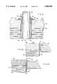
- FIG. 1is a perspective and partially sectional view of a quadpolar feedthrough filter capacitor embodying aspects of the present invention
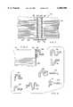
- FIG. 2is an electrical schematic of the assembly shown in FIG. 1;
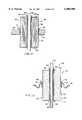
- FIG. 3is a sectional view of a unipolar hermetically sealed feedthrough filter capacitor embodying aspects of the present invention, illustrating a conductive terminal pin extending through a ceramic feedthrough filter capacitor which is, in turn, conductively coupled and mechanically attached to a conductive substrate;
- FIG. 4is an electrical schematic of the assembly shown in FIG. 3;
- FIG. 5is an enlarged fragmented sectional view taken generally of the area indicated by the line 5 in FIG. 3, illustrating details of a first hermetic seal joint between the terminal pin and the feedthrough filter capacitor;
- FIG. 6Ais an enlarged fragmented elevational view taken of the area indicated by the line 6A in FIG. 3, illustrating a second hermetic seal joint between the feedthrough filter capacitor and the conductive substrate;
- FIG. 6Bis an enlarged fragmented elevational section similar to that of FIG. 6A, illustrating an alternative second hermetic seal joint between the feedthrough filter capacitor and the conductive substrate;
- FIG. 7is an enlarged fragmented elevational section taken of the area indicated by the number 7 in FIG. 3, illustrating use of an optional nail-head-type terminal pin;
- FIG. 8is a fragmented elevational section similar to FIGS. 6A and 6B, illustrating use of a second hermetic seal joint between the feedthrough filter capacitor and a stress-relieving flange forming a portion of the conductive substrate;
- FIG. 9comprises elevational sectional views of various shaped stress-relieving flanges that may be utilized in the manner illustrated in FIG. 8 to relieve stress at the capacitor outside diameter or perimeter;
- FIG. 10is a perspective view of an alternate embodiment of a feedthrough filter capacitor assembly embodying aspects of the present invention, wherein the assembly incorporates a unipolar wire bond pad;
- FIG. 11is a partially fragmented perspective view of a multilayer tubular feedthrough filter capacitor mounted to a conductive substrate in accordance with aspects of the present invention
- FIG. 12is an enlarged sectional view taken generally along the line 12--12 of FIG. 11;
- FIG. 13is a sectional view similar to that illustrated in FIG. 12, illustrating a single layer tubular feedthrough filter capacitor assembly embodying aspects of the present invention, connected to a stress-relieving flange as illustrated in FIG. 9.
- the improved feedthrough filter capacitor assemblies 20-28comprise, generally, at least one conductive terminal pin 30, a conductive substrate 32 through which the terminal pin passes in non-conductive relation, and a ceramic feedthrough filter capacitor 34.
- the capacitor 34comprises a ceramic housing 36 that supports in spaced relation first and second electrode plate means 38 and 40.
- a passageway 42is provided through the feedthrough filter capacitor 34, through which the terminal pin 30 extends in conductive relation with the first electrode plate means 38.
- the second electrode plate means 40is, in turn, conductively coupled to the conductive substrate 32.
- hermetic seal joints 44 and 46are provided directly between the ceramic feedthrough filter capacitor 34 and, respectively, the conductive terminal pin 30 and the conductive substrate 32, to eliminate the need for a costly separate hermetic terminal pin subassembly.
- the feedthrough filter capacitor assemblies 20-28provide for shielding and decoupling of the conductive terminal pin 30 or lead of the type used, for example, in a cardiac pacemaker or cardioverter defibrillator, to prevent the passage of externally generated electromagnetic (EM) fields such as interference signals caused by digital cellular phones.
- EMelectromagnetic
- the feedthrough filter capacitor 34may be directly attached, by means of the second hermetic seal joint 46, to a stress-relieving flange 48 that forms a portion of the conductive substrate 32 and which is adapted for mounting onto a conductive pacemaker housing 50 (or other conductive shield structure) by welding, brazing, soldering or adhesive bonding, to support the terminal pin-carrying capacitor 34 assembly for feedthrough passage to the housing interior.
- Alternative forms of the inventioninclude wire bond pads 52 which facilitate internal lead connections.
- the feedthrough filter capacitor assemblies 20-26are designed such that the sensitive internal electrode plate means 38 and 40 are oriented toward the inside of the implantable device so that they cannot come into contact with body fluids.
- a noble metalsuch as gold is utilized in the hermetic seal joints 44 and 46 to withstand corrosion from body fluids.
- the present inventionis also applicable to a wide variety of other EMI filter applications, such as military or space electronic modules, where it is desirable to preclude the entry of EMI into a hermetically sealed housing containing sensitive electronic circuitry.
- FIGS. 1 and 2there is shown a quadpolar feedthrough filter capacitor assembly constructed in accordance with the principles of the present invention, wherein multiple feedthrough capacitors are provided in a substantially coplanar array within a common base structure, with each capacitor being placed in association with a respective terminal pin.
- the feedthrough filter capacitor assembly 20 of FIG. 1provides an example of how the features to be discussed below in connection with the assemblies of FIGS. 3-10 may be easily incorporated into a multi-polar capacitor assembly. Further, the assembly 20 illustrates the use of integrated alumina or capacitor cover layers 54 to provide a buffer between a fluid environment that could be harmful to the internal components of the feedthrough filter capacitor 34.
- the capacitor cover layers 54may be provided as the ceramic housing 36 is manufactured.
- an alumina wafer 56may be provided on the outboard side of the ceramic feedthrough filter capacitor housing 36.
- the alumina ceramic wafer 56may be co-fired, glass/frit fired or bonded with non-conductive thermal setting adhesives to the outboard side of the ceramic housing 36.
- FIG. 1further illustrates direct attachment between the ceramic feedthrough filter capacitor 34 to a standard H-flange 58.
- FIG. 2illustrates an electrical schematic corresponding to the feedthrough filter capacitor assembly 20 of FIG. 1.
- the conductive terminal pin 30comprises a platinum-iridium lead or other wire that extends through the passageway 42 of the ceramic housing 36.
- the first electrode plate means 38comprises a set of electrode plates extending radially outwardly from the passageway 42.
- the first set of electrode plates 38are conductively coupled together by means of, for example, palladium-silver metallization 60 applied to the inner surface of the passageway 42.
- a conductive adhesive filling 62is provided between the terminal pin and the inner passageway metallization.
- the first hermetic seal joint 44 between the terminal pin 30 and the ceramic housing 36 of the feedthrough capacitor 34is illustrated in greater detail.
- a first metallization layer 64is applied to the ceramic housing 36 adjacent to the upper end of the passageway 42.
- a metal braze 66is then applied over the metallization layer 64 to conductively couple and mechanically attach the terminal pin 30 to the metallization layer 64.
- the metallization layer 64is created by first sputtering down an adhesion layer such as titanium. Next nickel is sputtered or electroplated over the adhesion layer. Finally, and especially in the case of a medical implant application, gold is sputtered or electroplated over the nickel.
- the metallization layer 64may be deposited by plasma/electric arc discharge or electro-plating techniques.
- the second electrode plate means 40comprises a set of electrode plates, spaced from the first set of electrode plates 38 and extending from the outer radius of the ceramic housing 36 inwardly.
- the second set of electrode plates 40are coupled together by means of an outer metallization layer 68 which may be, for example, similar to the inner passageway metallization 60.
- the outer metallization layer 68may be formed in a similar manner to the first metallization layer 64 described above.
- a second metallization layer 70is applied about the periphery of the ceramic housing 36 and adjacent to the outer metallization layer 68 in the same manner as described above in connection with the first metallization layer 64.
- an adhesion layeris first sputtered down, such as titanium, after which nickel is sputtered or electroplated over the adhesion layer.
- goldis sputtered or electroplated over the nickel layer to complete the second metallization layer in preparation for application of the second metal braze 72.
- the metallization layer 68may be deposited by plasma/electric arc discharge or electro-plating techniques.
- a noble metal braze such as goldis preferred, especially in medical implant applications because of its known characteristics when implanted in the body. It is important that the metal braze conductively couples and mechanically attaches the second metallization layer 70 to the conductive substrate 32.
- the metal braze 72may overlap or replace the outer metallization layer 68 to ensure that the second set of electrode plates 40 is conductively coupled, through the metal braze 72, to the conductive substrate 32.
- a feature of the present inventionis that relatively high dielectric constant materials (for example, barium titanate with a dielectric constant of 2,000) are used to manufacture an integrated ceramic capacitor and hermetic seal.
- Ceramic dielectric materialssuch as barium titanate are not as strong as the alumina ceramic typically used to manufacture the hermetic seal subassembly in the prior art. Direct assembly of the ceramic capacitor results in stress to the capacitor due to the mismatch in thermal coefficients of expansion between the titanium pacemaker housing (or other metallic structure 50) and the capacitor dielectric. Particular care must be used to avoid cracking of the capacitor element. Accordingly, the use of dielectric materials with a relatively high modulus of toughness and/or stress relieving designs are desirable.
- FIG. 6Bwhich is similar to FIG. 6A, illustrates a novel wafer construction which integrates a stronger alumina ceramic layer 56 in the area of the first and second hermetic seal joints 44 and 46, which is able to withstand both welding stresses and the mismatch in thermal coefficients of expansion.
- the alumina ceramic wafer 56(also shown in FIG. 1) may be co-fired, glass/frit fired or bonded with non-conductive thermal setting adhesives 74 to the ceramic capacitor housing 36.
- the mechanical and conductive attachment between the capacitor 34 and the conductive substrate 32is similar to that described above.
- an outer metallization layer 68is provided to conductively couple together with second set of electrode plates 40.
- the second matallization layer 70is applied adjacent to the outer metallization layer (or the second metallization layer may replace the outer metallization layer if applied to the entire outer surface of the ceramic housing 36) in the manner described above.
- the gold braze 72is then applied to effect the mechanical and conductive coupling between the feedthrough filter capacitor 34 and the conductive substrate 36 which, in this case, is a titanium pacemaker can, header or flange.
- An additional feature not illustrated in the preceding embodimentis the use of a conductive adhesive 76 between the outer metallization layer 68 and the conductive substrate 32 to help ensure a conductive connection between the second set of electrode plates 40 and the conductive substrate 32.
- FIG. 7illustrates an alternative configuration of the inboard side of the ceramic feedthrough filter capacitor 34 wherein a nail-head lead 78 provides an optional wire bond pad 80.
- the padmay be sputtered onto the previously formed lead, plated to the tip of the formed lead wire, or attached by brazing or the like. Further, the wire bond pad may be simply manufactured with the conductive terminal pin 30 in the form of the nail-head lead 78 shown.
- FIG. 8illustrates an alternative embodiment wherein a stress-relieving flange 48 is attached directly to the outer periphery of the ceramic housing 36 by means of the second hermetic seal joint 46.
- FIG. 9illustrates a variety of different stress-relieving flange 48 shapes and sizes.
- An advantage of utilizing stress-relieving flangesis that the integrated feedthrough capacitor/hermetic seal can be manufactured complete with a stress-relieving flange 48 which is ready for installation by welding.
- the stress-relieving flange 48may be used in conjunction with either the ceramic feedthrough filter capacitor 34 by itself or with the capacitor/alumina wafer 56 described above.
- FIG. 10shows an alternative to having the lead enter into the inside of the housing.
- implantable device applicationsfor example where a flex cable is utilized
- wire bond pad 80is formed of gold which is either plated or thick film deposited onto the surface of the ceramic housing 36.
- the surface of the ceramic housing 36is prepared for the gold attachment by sputtering, plating or conductive glass frit firing.
- FIGS. 11 and 12show a typical multi-layer tubular capacitor that is attached to both a conductive terminal pin 30 extending centrally therethrough and to a supporting conductive substrate 32 utilizing the first and second hermetic seal joints 44 and 46 of the invention.
- Tubular capacitorsare common in the art and are very inexpensive to fabricate because their geometry lends itself to high volume green ceramic extrusion or rolling processes.
- Tubular capacitorsmay be multilayered as illustrated in FIGS. 11 and 12, or single layer (extruded) as illustrated in FIG. 13.
- tubular capacitorsare very effective high frequency filter elements.
- inductive elementsmay be added to the inside of the tubular capacitor to form L or Pl type low pass filter surface.
- the first metallization layer 64is formed over an upper surface of the ceramic housing 36 to conductively couple together the first set of electrode plates 38.
- the first metallization layerextends partially into the upper end of the passageway 42.
- the first metal braze 66is applied to conductively couple together and mechanically attach the upper end of the feedthrough filter capacitor 34 to the terminal pin 30.
- the second metallization layeris applied over the opposite end of the tubular feedthrough filter capacitor 34 so as to conductively couple together the second set of electrode plates 40.
- the second metallization layer 70extends from the lower end of the capacitor 34 on its outer surface upwardly to the point of attachment between the capacitor 34 and the conductive substrate 32.
- the second metal braze 72may then be applied over the second metallization layer to conductively couple together and mechanically attach the tubular feedthrough filter capacitor 34 to the conductive substrate 32.
- FIG. 13illustrates a single layer (extruded) tubular capacitor.
- the inner passageway metallization 60functions as the first electrode plate means 38.
- the metal braze 66conductively couples the inner passageway metallization 60 (which is serving as the first electrode plate means 38) to the conductive terminal pin 30.
- the radially outwardly facing surface of the ceramic housing 36is sputtered to form the second metallization layer 70 which also serves as the second electrode plate means 40.
- the stress-relieving flange 48 illustratedmay then be conductively coupled and mechanically attached to the second metallization layer 70 by means of the second metal braze 72 as shown.
- a novel ceramic feedthrough capacitor assemblywhich also forms a hermetic seal is provided for shielding and decoupling of a conductive terminal pin or lead of the type used, for example, in an implantable medical device such as a cardiac pacemaker or cardioverter defibrillator, to prevent the passage of externally generated electromagnetic (EM) fields such as interference signals caused by additional cellular phones.
- EMelectromagnetic
- the ceramic feedthrough capacitor and hermetic sealinto a single unit, the costly separate hermetic terminal subassembly is eliminated.
- the assemblies described abovemay be utilized in connection with a unipolar feedthrough filter capacitor as well as multiple feedthrough filter capacitors provided in a substantially coplanar array within a common base structure.
- the use of stress-relieving flangesmay further advantageously permit the selection of materials which will withstand both welding stresses and the mismatch in thermal coefficients of expansion inherent in the construction of ceramic feedthrough filter capacitors.
- the exposed capacitor surfacemay be overcoated with a nonconductive epoxy or polyamid to enhance its moisture and solvent resistance. Accordingly, the invention is not to be limited, except as by the appended claims.
Landscapes
- Engineering & Computer Science (AREA)
- Power Engineering (AREA)
- Health & Medical Sciences (AREA)
- Life Sciences & Earth Sciences (AREA)
- General Health & Medical Sciences (AREA)
- Biomedical Technology (AREA)
- Nuclear Medicine, Radiotherapy & Molecular Imaging (AREA)
- Radiology & Medical Imaging (AREA)
- Manufacturing & Machinery (AREA)
- Animal Behavior & Ethology (AREA)
- Microelectronics & Electronic Packaging (AREA)
- Public Health (AREA)
- Veterinary Medicine (AREA)
- Electrotherapy Devices (AREA)
- Thermistors And Varistors (AREA)
- Prostheses (AREA)
- Fixed Capacitors And Capacitor Manufacturing Machines (AREA)
Abstract
Description
Claims (26)
Priority Applications (6)
| Application Number | Priority Date | Filing Date | Title |
|---|---|---|---|
| US08/969,480US6008980A (en) | 1997-11-13 | 1997-11-13 | Hermetically sealed EMI feedthrough filter capacitor for human implant and other applications |
| EP98121396AEP0916364B1 (en) | 1997-11-13 | 1998-11-11 | Hermetically sealed emi feedthrough filter capacitor for human implant and other applications |
| DE69835991TDE69835991T2 (en) | 1997-11-13 | 1998-11-11 | Hermetically sealed EMI feedthrough filter for human implant and other applications. |
| AT98121396TATE340603T1 (en) | 1997-11-13 | 1998-11-11 | HERMETIC SEALED EMI FEEDTHROUGH FILTER FOR HUMAN IMPLANT AND OTHER APPLICATIONS. |
| US09/460,879US6275369B1 (en) | 1997-11-13 | 1999-12-14 | EMI filter feedthough terminal assembly having a capture flange to facilitate automated assembly |
| US09/812,371US6643903B2 (en) | 1997-11-13 | 2001-03-16 | Process for manufacturing an EMI filter feedthrough terminal assembly |
Applications Claiming Priority (1)
| Application Number | Priority Date | Filing Date | Title |
|---|---|---|---|
| US08/969,480US6008980A (en) | 1997-11-13 | 1997-11-13 | Hermetically sealed EMI feedthrough filter capacitor for human implant and other applications |
Related Child Applications (1)
| Application Number | Title | Priority Date | Filing Date |
|---|---|---|---|
| US09/460,879Continuation-In-PartUS6275369B1 (en) | 1997-11-13 | 1999-12-14 | EMI filter feedthough terminal assembly having a capture flange to facilitate automated assembly |
Publications (1)
| Publication Number | Publication Date |
|---|---|
| US6008980Atrue US6008980A (en) | 1999-12-28 |
Family
ID=25515613
Family Applications (1)
| Application Number | Title | Priority Date | Filing Date |
|---|---|---|---|
| US08/969,480Expired - LifetimeUS6008980A (en) | 1997-11-13 | 1997-11-13 | Hermetically sealed EMI feedthrough filter capacitor for human implant and other applications |
Country Status (4)
| Country | Link |
|---|---|
| US (1) | US6008980A (en) |
| EP (1) | EP0916364B1 (en) |
| AT (1) | ATE340603T1 (en) |
| DE (1) | DE69835991T2 (en) |
Cited By (137)
| Publication number | Priority date | Publication date | Assignee | Title |
|---|---|---|---|---|
| US6104161A (en)* | 1999-05-10 | 2000-08-15 | General Motors Corporation | Capacitive AC isolation apparatus for electric vehicle battery charging systems |
| US6414835B1 (en)* | 2000-03-01 | 2002-07-02 | Medtronic, Inc. | Capacitive filtered feedthrough array for an implantable medical device |
| US6459080B1 (en)* | 1998-06-12 | 2002-10-01 | Agilent Technologies, Inc. | Miniaturized device for separating the constituents of a sample and delivering the constituents of the separated sample to a mass spectrometer |
| US6490148B1 (en) | 2002-01-02 | 2002-12-03 | Greatbatch-Hittman, Incorporated | Installation of filter capacitors into feedthroughs for implantable medical devices |
| US6529103B1 (en) | 2000-09-07 | 2003-03-04 | Greatbatch-Sierra, Inc. | Internally grounded feedthrough filter capacitor with improved ground plane design for human implant and other applications |
| US6545854B2 (en) | 2001-05-25 | 2003-04-08 | Presidio Components, Inc. | Fringe-field non-overlapping-electrodes discoidal feed-through ceramic filter capacitor with high breakdown voltage |
| US6567259B2 (en) | 2001-05-31 | 2003-05-20 | Greatbatch-Sierra, Inc. | Monolithic ceramic capacitor with barium titinate dielectric curie point optimized for active implantable medical devices operating at 37° C. |
| WO2003073449A1 (en) | 2002-02-28 | 2003-09-04 | Greatbatch-Sierra, Inc. | Emi feedthrough filter terminal assembly for human implant applications utilizing oxide resistant biostable conductive pads for reliable electrical attachments |
| US6619763B2 (en) | 2001-05-25 | 2003-09-16 | Presidio Components, Inc. | Feed-through filter capacitor with non-overlapping electrodes |
| US20030191505A1 (en)* | 2002-04-09 | 2003-10-09 | Mark Gryzwa | Magnetic structure for feedthrough filter assembly |
| US6643903B2 (en)* | 1997-11-13 | 2003-11-11 | Greatbatch-Sierra, Inc. | Process for manufacturing an EMI filter feedthrough terminal assembly |
| US20030225372A1 (en)* | 2002-05-31 | 2003-12-04 | Christenson Steven R. | Implantable infusion device with motor connection and seal system |
| US20030231455A1 (en)* | 2001-05-25 | 2003-12-18 | Devoe Daniel F. | Capacitor with high voltage breakdown threshold |
| US20040020657A1 (en)* | 2002-07-31 | 2004-02-05 | Patel Dinesh R. | Multiple interventionless actuated downhole valve and method |
| US20040125535A1 (en)* | 2002-12-30 | 2004-07-01 | Behrooz Mehr | Capacitor method and apparatus |
| US20040201947A1 (en)* | 2002-02-28 | 2004-10-14 | Stevenson Robert A. | EMI filter capacitors designed for direct body fluid exposure |
| US20040232204A1 (en)* | 2003-05-23 | 2004-11-25 | Wolf William D. | Brazing fixtures and methods for fabricating brazing fixtures used for making feed-through assemblies |
| US20040231877A1 (en)* | 2003-05-23 | 2004-11-25 | Wolf William D. | Feed-through assemblies having terminal pins comprising platinum and methods for fabricating same |
| US20040257747A1 (en)* | 2003-05-23 | 2004-12-23 | Stevenson Robert A. | Inductor capacitor EMI filter for human implant applications |
| US20050007718A1 (en)* | 2003-02-27 | 2005-01-13 | Stevenson Robert A. | EMI filter terminal assembly with wire bond pads for human implant applications |
| US6858955B2 (en)* | 2000-08-21 | 2005-02-22 | Johnson Electric S.A. | End cap assembly |
| US20050041366A1 (en)* | 1999-03-23 | 2005-02-24 | Medtronic, Inc. | Implantable medical device having flat electrolytic capacitor with differing sized anode and cathode layers |
| US20050060003A1 (en)* | 2003-09-12 | 2005-03-17 | Taylor William J. | Feedthrough apparatus with noble metal-coated leads |
| US6882248B2 (en) | 2000-09-07 | 2005-04-19 | Greatbatch-Sierra, Inc. | EMI filtered connectors using internally grounded feedthrough capacitors |
| US20050095442A1 (en)* | 2003-10-30 | 2005-05-05 | Byers Charles L. | Ceramic to noble metal braze and method of manufacture |
| US20050197677A1 (en)* | 2004-02-12 | 2005-09-08 | Stevenson Robert A. | Apparatus and process for reducing the susceptability of active implantable medical devices to medical procedures such as magnetic resonance imaging |
| US20060023397A1 (en)* | 2004-07-27 | 2006-02-02 | Greatbatch-Sierra, Inc. | Feedthrough capacitor filter assemblies with laminar flow delaminations for helium leak detection |
| US20060028784A1 (en)* | 2004-05-10 | 2006-02-09 | Greatbatch-Sierra, Inc. | Device to protect an active implantable medical device feedthrough capacitor from stray laser weld strikes, and related manufacturing process |
| US20060085043A1 (en)* | 2004-04-15 | 2006-04-20 | Greatbatch-Sierra, Inc. | Apparatus and process for reducing the susceptibility of active implantable medical devices to medical procedures such as magentic resonance imaging |
| EP1695736A1 (en) | 2005-02-23 | 2006-08-30 | Greatbatch-Sierra, Inc. | Shielded RF distance telemetry pin for active implantable medical devices |
| US20060247714A1 (en)* | 2005-04-28 | 2006-11-02 | Taylor William J | Glass-to-metal feedthrough seals having improved durability particularly under AC or DC bias |
| US20060247684A1 (en)* | 2001-04-13 | 2006-11-02 | Greatbatch-Sierra, Inc. | Band stop filter employing a capacitor and an inductor tank circuit to enhance mri compatibility of active medical devices |
| US20060259093A1 (en)* | 2003-02-27 | 2006-11-16 | Greatbatch-Sierra, Inc. | Hermetic feedthrough terminal assembly with wire bond pads for human implant applications |
| US20070067007A1 (en)* | 2005-05-25 | 2007-03-22 | Alfred E. Mann Foundation For Scientific Research | Hermetically sealed three-dimensional electrode array |
| US20070112398A1 (en)* | 2005-11-11 | 2007-05-17 | Greatbatch Ltd. | Tank filters placed in series with the lead wires or circuits of active medical devices to enhance mri compatibility |
| US20070123949A1 (en)* | 2005-11-11 | 2007-05-31 | Greatbatch Ltd. | Low loss band pass filter for rf distance telemetry pin antennas of active implantable medical devices |
| US20070134985A1 (en)* | 2005-12-12 | 2007-06-14 | Frysz Christine A | Feedthrough Filter Capacitor Assemblies Having Low Cost Terminal Pins |
| US20070239223A1 (en)* | 2006-03-31 | 2007-10-11 | Engmark David B | Feedthrough array for use in implantable medical devices |
| US20070260282A1 (en)* | 2003-09-12 | 2007-11-08 | Taylor William J | Feedthrough apparatus with noble metal-coated leads |
| US20070279834A1 (en)* | 2006-06-01 | 2007-12-06 | Greatbatch, Ltd. | Feedthrough capacitor having reduced self resonance insertion loss dip |
| US20080049376A1 (en)* | 1998-11-04 | 2008-02-28 | Greatbatch Ltd. | Non-ferromagnetic tank filters in lead wires of active implantable medical devices to enhance mri compatibility |
| US20080065181A1 (en)* | 2001-04-13 | 2008-03-13 | Greatbatch, Ltd. | Rfid detection and identification system for implantable medical lead systems |
| US20080071313A1 (en)* | 2005-11-11 | 2008-03-20 | Greatbatch Ltd. | Tank filters utilizing very low k materials, in series with lead wires or circuits of active medical devices to enhance mri compatibility |
| US20080116997A1 (en)* | 2001-04-13 | 2008-05-22 | Greatbatch Ltd. | Cylindrical bandstop filters for medical lead systems |
| US20080132987A1 (en)* | 2001-04-13 | 2008-06-05 | Greatbatch Ltd. | Medical lead system utilizing electromagnetic bandstop filters |
| US20080161886A1 (en)* | 2006-06-08 | 2008-07-03 | Greatbatch Ltd. | Tank filters adaptable for placement with a guide wire, in series with the lead wires or circuits of active medical devices to enhance mri compatibility |
| US20080195180A1 (en)* | 2006-06-08 | 2008-08-14 | Greatbatch Ltd. | Low loss band pass filter for rf distance telemetry pin antennas of active implantable medical devices |
| US20080294220A1 (en)* | 2006-04-03 | 2008-11-27 | Greatbatch Ltd. | Feedthrough filter terminal assemblies with breathable components to facilitate leak testing |
| US20090079517A1 (en)* | 2007-09-25 | 2009-03-26 | Iyer Rajesh V | Novel capacitive elements and filtered feedthrough elements for implantable medical devices |
| US20090079519A1 (en)* | 2007-09-25 | 2009-03-26 | Iyer Rajesh V | Novel capacitive elements and filtered feedthrough elements for implantable medical devices |
| US20090080140A1 (en)* | 2007-09-20 | 2009-03-26 | Iyer Rajesh V | Filtered feedthrough assemblies for implantable devices and methods of manufacture |
| US20090079518A1 (en)* | 2007-09-25 | 2009-03-26 | Iyer Rajesh V | Novel capacitive elements and filtered feedthrough elements for implantable medical devices |
| US20090116167A1 (en)* | 2002-02-28 | 2009-05-07 | Greatbatch Ltd. | Passive electronic network components designed for direct body fluid exposure |
| US20090117861A1 (en)* | 2007-11-06 | 2009-05-07 | Qualcomm Incorporated | Personal health modules supported by portable communication devices |
| US7561915B1 (en) | 2004-12-17 | 2009-07-14 | Cardiac Pacemakers, Inc. | MRI system having implantable device safety features |
| US20090259265A1 (en)* | 2002-02-28 | 2009-10-15 | Greatbatch Ltd. | Electronic network components utilizing biocompatible conductive adhesives for direct body fluid exposure |
| WO2009117599A3 (en)* | 2008-03-20 | 2010-01-07 | Greatbatch Ltd. | Shielded three-terminal flat-through emi/energy dissipating filter |
| US20100100164A1 (en)* | 2006-11-09 | 2010-04-22 | Greatbatch Ltd. | Capacitor and inductor elements physically disposed in series whose lumped parameters are electrically connected in parallel to form a bandstop filter |
| US7719854B2 (en) | 2003-07-31 | 2010-05-18 | Cardiac Pacemakers, Inc. | Integrated electromagnetic interference filters and feedthroughs |
| US7822460B2 (en) | 1998-11-04 | 2010-10-26 | Surgi-Vision, Inc. | MRI-guided therapy methods and related systems |
| US20100302702A1 (en)* | 2009-06-02 | 2010-12-02 | Astec International Limited | Feedthrough Capacitor Assemblies |
| US20110094768A1 (en)* | 2009-10-28 | 2011-04-28 | Pacesetter, Inc. | Implantable medical device having feedthru with an integrated interconnect/filter substrate |
| US20110137359A1 (en)* | 2009-12-08 | 2011-06-09 | Stubbs Scott R | Implantable medical device with automatic tachycardia detection and control in mri environments |
| EP2357017A1 (en) | 2010-02-17 | 2011-08-17 | Greatbatch Ltd. | Emi filter employing a capacitor and an inductor tank circuit having optimum component values |
| US20110213233A1 (en)* | 2006-06-08 | 2011-09-01 | Greatbatch Ltd. | Tank filters placed in series with the lead wires or circuits of active medical devices to enhance mri compatibility |
| US8014867B2 (en) | 2004-12-17 | 2011-09-06 | Cardiac Pacemakers, Inc. | MRI operation modes for implantable medical devices |
| CN1965473B (en)* | 2004-06-10 | 2011-09-28 | 约翰美兹林高协会公司 | Device and method for tamper resistant filter trap |
| US8032228B2 (en) | 2007-12-06 | 2011-10-04 | Cardiac Pacemakers, Inc. | Method and apparatus for disconnecting the tip electrode during MRI |
| USRE42856E1 (en) | 2002-05-29 | 2011-10-18 | MRI Interventions, Inc. | Magnetic resonance probes |
| EP2392382A1 (en) | 2005-11-11 | 2011-12-07 | Greatbatch Ltd. | Tank filters placed in series with the lead wires or circuits of active medical devices to enhance MRI compatibility |
| US8086321B2 (en) | 2007-12-06 | 2011-12-27 | Cardiac Pacemakers, Inc. | Selectively connecting the tip electrode during therapy for MRI shielding |
| US20120071956A1 (en)* | 2006-06-08 | 2012-03-22 | Greatbatch Ltd. | Implantable lead bandstop filter employing an inductive coil with parasitic capacitance to enhance mri compatibility of active medical devices |
| US8160717B2 (en) | 2008-02-19 | 2012-04-17 | Cardiac Pacemakers, Inc. | Model reference identification and cancellation of magnetically-induced voltages in a gradient magnetic field |
| US8180453B2 (en) | 1999-03-24 | 2012-05-15 | Second Sight Medical Products, Inc. | Electrode array for neural stimulation |
| US8219208B2 (en) | 2001-04-13 | 2012-07-10 | Greatbatch Ltd. | Frequency selective passive component networks for active implantable medical devices utilizing an energy dissipating surface |
| US8224462B2 (en) | 2005-11-11 | 2012-07-17 | Greatbatch Ltd. | Medical lead system utilizing electromagnetic bandstop filters |
| US20120181079A1 (en)* | 2011-01-18 | 2012-07-19 | Fisher Controls International Llc | Capacitor Coupled Cable Shield Feedthrough |
| US8230564B1 (en)* | 2010-01-29 | 2012-07-31 | The United States Of America As Represented By The Secretary Of The Air Force | Method of making a millimeter wave transmission line filter |
| US20120221098A1 (en)* | 2000-11-17 | 2012-08-30 | Advanced Bio Prosthetic Surfaces, Ltd., A Wholly Owned Subsidiary Of Palmaz Scientific, Inc. | Endoluminal device for in vivo delivery of bioactive agents |
| US8259435B2 (en) | 2010-11-01 | 2012-09-04 | Avx Corporation | Hermetically sealed wet electrolytic capacitor |
| US8311637B2 (en) | 2008-02-11 | 2012-11-13 | Cardiac Pacemakers, Inc. | Magnetic core flux canceling of ferrites in MRI |
| US8386047B2 (en) | 2010-07-15 | 2013-02-26 | Advanced Bionics | Implantable hermetic feedthrough |
| US8447414B2 (en) | 2008-12-17 | 2013-05-21 | Greatbatch Ltd. | Switched safety protection circuit for an AIMD system during exposure to high power electromagnetic fields |
| US8451586B2 (en) | 2011-09-13 | 2013-05-28 | Avx Corporation | Sealing assembly for a wet electrolytic capacitor |
| US8457760B2 (en) | 2001-04-13 | 2013-06-04 | Greatbatch Ltd. | Switched diverter circuits for minimizing heating of an implanted lead and/or providing EMI protection in a high power electromagnetic field environment |
| EP2617461A1 (en) | 2012-01-16 | 2013-07-24 | Greatbatch Ltd. | Co-fired hermetically sealed feedthrough with alumina substrate and platinum filled via for an active implantable medical device |
| US8509913B2 (en) | 2001-04-13 | 2013-08-13 | Greatbatch Ltd. | Switched diverter circuits for minimizing heating of an implanted lead and/or providing EMI protection in a high power electromagnetic field environment |
| US8514547B2 (en) | 2010-11-01 | 2013-08-20 | Avx Corporation | Volumetrically efficient wet electrolytic capacitor |
| US20130223031A1 (en)* | 2010-12-02 | 2013-08-29 | Micro-Epsilon Messtechnik Gmbh & Co. Kg | Sensor comprising a multi-layered ceramic substrate and method for its production |
| US8538530B1 (en)* | 2008-11-19 | 2013-09-17 | Advanced Bionics | Hermetically sealed feedthrough case |
| US8552311B2 (en) | 2010-07-15 | 2013-10-08 | Advanced Bionics | Electrical feedthrough assembly |
| US8571661B2 (en) | 2008-10-02 | 2013-10-29 | Cardiac Pacemakers, Inc. | Implantable medical device responsive to MRI induced capture threshold changes |
| US8605411B2 (en) | 2010-09-16 | 2013-12-10 | Avx Corporation | Abrasive blasted conductive polymer cathode for use in a wet electrolytic capacitor |
| US8639331B2 (en) | 2009-02-19 | 2014-01-28 | Cardiac Pacemakers, Inc. | Systems and methods for providing arrhythmia therapy in MRI environments |
| US8644936B2 (en) | 2012-01-09 | 2014-02-04 | Medtronic, Inc. | Feedthrough assembly including electrical ground through feedthrough substrate |
| US8644002B2 (en) | 2011-05-31 | 2014-02-04 | Medtronic, Inc. | Capacitor including registration feature for aligning an insulator layer |
| US8712544B2 (en) | 2001-04-13 | 2014-04-29 | Greatbatch Ltd. | Electromagnetic shield for a passive electronic component in an active medical device implantable lead |
| US20140183983A1 (en)* | 2012-12-28 | 2014-07-03 | Zhongshan Broad-Ocean Motor Manufacturing Co., Ltd. | Plastic-package motor |
| US8844103B2 (en) | 2011-09-01 | 2014-09-30 | Medtronic, Inc. | Methods for making feedthrough assemblies including a capacitive filter array |
| US8989870B2 (en) | 2001-04-13 | 2015-03-24 | Greatbatch Ltd. | Tuned energy balanced system for minimizing heating and/or to provide EMI protection of implanted leads in a high power electromagnetic field environment |
| US9031670B2 (en) | 2006-11-09 | 2015-05-12 | Greatbatch Ltd. | Electromagnetic shield for a passive electronic component in an active medical device implantable lead |
| US9059435B2 (en) | 2012-01-27 | 2015-06-16 | Medtronic, Inc. | Medical device battery enclosure |
| US9108066B2 (en) | 2008-03-20 | 2015-08-18 | Greatbatch Ltd. | Low impedance oxide resistant grounded capacitor for an AIMD |
| US20150302991A1 (en)* | 2014-04-16 | 2015-10-22 | Samsung Electro-Mechanics Co., Ltd. | Multilayer ceramic capacitor and circuit board for mounting the same |
| US9242090B2 (en) | 2001-04-13 | 2016-01-26 | MRI Interventions Inc. | MRI compatible medical leads |
| US9251960B2 (en) | 2009-03-19 | 2016-02-02 | Greatbatch Ltd. | Dual stage EMI filter and offset highly efficient multi-polar active capacitor electrodes for an active implantable medical device |
| US9248283B2 (en) | 2001-04-13 | 2016-02-02 | Greatbatch Ltd. | Band stop filter comprising an inductive component disposed in a lead wire in series with an electrode |
| US9295828B2 (en) | 2001-04-13 | 2016-03-29 | Greatbatch Ltd. | Self-resonant inductor wound portion of an implantable lead for enhanced MRI compatibility of active implantable medical devices |
| US9427596B2 (en) | 2013-01-16 | 2016-08-30 | Greatbatch Ltd. | Low impedance oxide resistant grounded capacitor for an AIMD |
| US9431814B2 (en) | 2012-02-15 | 2016-08-30 | Cardiac Pacemakers, Inc. | Ferrule for implantable medical device |
| US9468750B2 (en) | 2006-11-09 | 2016-10-18 | Greatbatch Ltd. | Multilayer planar spiral inductor filter for medical therapeutic or diagnostic applications |
| USRE46699E1 (en) | 2013-01-16 | 2018-02-06 | Greatbatch Ltd. | Low impedance oxide resistant grounded capacitor for an AIMD |
| US9889306B2 (en) | 2012-01-16 | 2018-02-13 | Greatbatch Ltd. | Hermetically sealed feedthrough with co-fired filled via and conductive insert for an active implantable medical device |
| US9931514B2 (en) | 2013-06-30 | 2018-04-03 | Greatbatch Ltd. | Low impedance oxide resistant grounded capacitor for an AIMD |
| EP3320950A1 (en) | 2016-11-10 | 2018-05-16 | Greatbatch Ltd. | Feedthrough assembly for active implantable medical device |
| EP3326692A1 (en) | 2016-11-08 | 2018-05-30 | Greatbatch Ltd. | Feedthrough for an implantable medical device having a composite conductive lead |
| EP3345652A1 (en) | 2017-01-06 | 2018-07-11 | Greatbatch Ltd. | Method for manufacturing a feedthrough for an active implantable medical device |
| US10080889B2 (en) | 2009-03-19 | 2018-09-25 | Greatbatch Ltd. | Low inductance and low resistance hermetically sealed filtered feedthrough for an AIMD |
| US10154616B2 (en) | 2012-09-05 | 2018-12-11 | Avx Corporation | Electromagnetic interference filter for implanted electronics |
| US20180353762A1 (en)* | 2017-06-09 | 2018-12-13 | Medtronic, Inc. | Feedthrough assembly including ferrule with tapered extension(s) |
| US10195449B2 (en) | 2015-05-28 | 2019-02-05 | Forschungszentrum Juelich Gmbh | Housing for a medical implant with an electrical transmission |
| US10213611B2 (en)* | 2015-06-30 | 2019-02-26 | Osong Medical Innovation Foundation | Method of manufacturing feedthrough |
| EP3449973A1 (en) | 2017-08-30 | 2019-03-06 | Greatbatch Ltd. | Hermetically sealed filtered feedthrough assembly |
| US10249415B2 (en) | 2017-01-06 | 2019-04-02 | Greatbatch Ltd. | Process for manufacturing a leadless feedthrough for an active implantable medical device |
| US10350421B2 (en) | 2013-06-30 | 2019-07-16 | Greatbatch Ltd. | Metallurgically bonded gold pocket pad for grounding an EMI filter to a hermetic terminal for an active implantable medical device |
| US10363425B2 (en) | 2015-06-01 | 2019-07-30 | Avx Corporation | Discrete cofired feedthrough filter for medical implanted devices |
| US10449375B2 (en) | 2016-12-22 | 2019-10-22 | Greatbatch Ltd. | Hermetic terminal for an AIMD having a pin joint in a feedthrough capacitor or circuit board |
| US10561837B2 (en) | 2011-03-01 | 2020-02-18 | Greatbatch Ltd. | Low equivalent series resistance RF filter for an active implantable medical device utilizing a ceramic reinforced metal composite filled via |
| US10874865B2 (en) | 2017-11-06 | 2020-12-29 | Avx Corporation | EMI feedthrough filter terminal assembly containing a resin coating over a hermetically sealing material |
| US10881867B2 (en) | 2012-01-16 | 2021-01-05 | Greatbatch Ltd. | Method for providing a hermetically sealed feedthrough with co-fired filled via for an active implantable medical device |
| US10905888B2 (en) | 2018-03-22 | 2021-02-02 | Greatbatch Ltd. | Electrical connection for an AIMD EMI filter utilizing an anisotropic conductive layer |
| US10912945B2 (en) | 2018-03-22 | 2021-02-09 | Greatbatch Ltd. | Hermetic terminal for an active implantable medical device having a feedthrough capacitor partially overhanging a ferrule for high effective capacitance area |
| CN112820544A (en)* | 2021-02-09 | 2021-05-18 | 福建欧中电子有限公司 | High-reliability multilayer ceramic through capacitor and manufacturing method thereof |
| US11198014B2 (en) | 2011-03-01 | 2021-12-14 | Greatbatch Ltd. | Hermetically sealed filtered feedthrough assembly having a capacitor with an oxide resistant electrical connection to an active implantable medical device housing |
| US11351387B2 (en) | 2012-01-16 | 2022-06-07 | Greatbatch Ltd. | Method of manufacturing a singulated feedthrough insulator for a hermetic seal of an active implantable medical device incorporating a post conductive paste filled pressing step |
| US11648409B2 (en) | 2008-03-20 | 2023-05-16 | Greatbatch Ltd. | Ground electrical path from an MLCC filter capacitor on an AIMD circuit board to the ferrule of a hermetic feedthrough |
| US12246183B1 (en)* | 2023-10-06 | 2025-03-11 | Greatbatch Ltd. | Self-centering polymeric washer that prevents misalignment when positioned between a feedthrough and a circuit board supporting EMI filter capacitors for a medical device |
Families Citing this family (17)
| Publication number | Priority date | Publication date | Assignee | Title |
|---|---|---|---|---|
| EP1077514A3 (en)* | 1999-08-19 | 2001-10-24 | FILTEC FILTERTECHNOLOGIE FUR DIE ELEKTRONIKINDUSTRIE GmbH | Multiple filter |
| DE19957189A1 (en) | 1999-11-20 | 2001-05-23 | Biotronik Mess & Therapieg | Multipolar electric filter insert for implantable electronic therapy device, e.g. heart pacemaker or defibrillator; has insert body and filter block connected to freely project into pacemaker casing |
| EP1109180B1 (en) | 1999-12-14 | 2012-02-08 | Greatbatch Ltd. | Emi Filter feedthrough terminal assembly |
| FR2811900B1 (en)* | 2000-07-19 | 2003-02-07 | Eurofarad | FILTER ASSEMBLY FOR AN IMPLANTABLE ELECTRICAL STIMULATOR HAVING A ROBUST THERMAL VARIATION CAPACITOR |
| US8239026B2 (en) | 2005-09-28 | 2012-08-07 | St. Jude Medical Ab | Implantable medical device with a voltage protection circuit |
| US7803014B2 (en) | 2006-03-30 | 2010-09-28 | Cardiac Pacemakers, Inc. | Implantable medical device assembly and manufacturing method |
| US8326425B2 (en)* | 2006-03-30 | 2012-12-04 | Cardiac Pacemakers, Inc. | Feedthrough connector for implantable device |
| DE102009045106A1 (en)* | 2009-09-29 | 2011-03-31 | Robert Bosch Gmbh | Through capacitor |
| US9478959B2 (en) | 2013-03-14 | 2016-10-25 | Heraeus Deutschland GmbH & Co. KG | Laser welding a feedthrough |
| US9431801B2 (en) | 2013-05-24 | 2016-08-30 | Heraeus Deutschland GmbH & Co. KG | Method of coupling a feedthrough assembly for an implantable medical device |
| US9403023B2 (en) | 2013-08-07 | 2016-08-02 | Heraeus Deutschland GmbH & Co. KG | Method of forming feedthrough with integrated brazeless ferrule |
| US9504841B2 (en) | 2013-12-12 | 2016-11-29 | Heraeus Deutschland GmbH & Co. KG | Direct integration of feedthrough to implantable medical device housing with ultrasonic welding |
| US9610451B2 (en) | 2013-12-12 | 2017-04-04 | Heraeus Deutschland GmbH & Co. KG | Direct integration of feedthrough to implantable medical device housing using a gold alloy |
| US9610452B2 (en) | 2013-12-12 | 2017-04-04 | Heraeus Deutschland GmbH & Co. KG | Direct integration of feedthrough to implantable medical device housing by sintering |
| US9138821B2 (en)* | 2014-01-17 | 2015-09-22 | Medtronic, Inc. | Methods for simultaneously brazing a ferrule and lead pins |
| EP3900782B1 (en) | 2020-02-21 | 2023-08-09 | Heraeus Medical Components, LLC | Ferrule with strain relief spacer for implantable medical device |
| EP4226968B1 (en) | 2020-02-21 | 2025-04-30 | Heraeus Medical Components, LLC | Ferrule for non-planar medical device housing |
Citations (23)
| Publication number | Priority date | Publication date | Assignee | Title |
|---|---|---|---|---|
| US2756375A (en)* | 1952-02-06 | 1956-07-24 | Sprague Electric Co | Feed-through capacitors |
| US3235939A (en)* | 1962-09-06 | 1966-02-22 | Aerovox Corp | Process for manufacturing multilayer ceramic capacitors |
| US3920888A (en)* | 1974-06-04 | 1975-11-18 | Nuclear Battery Corp | Electrical feed-through assembly suitable for electronic devices implantable in a human body |
| US4083022A (en)* | 1976-10-12 | 1978-04-04 | Bunker Ramo Corporation | Planar pi multi-filter having a ferrite inductance for pin filters in electrical connectors |
| US4144509A (en)* | 1977-01-12 | 1979-03-13 | Bunker Ramo Corporation | Filter connector |
| US4148003A (en)* | 1977-07-08 | 1979-04-03 | Globe-Union Inc. | Series feed-through capacitor |
| US4152540A (en)* | 1977-05-03 | 1979-05-01 | American Pacemaker Corporation | Feedthrough connector for implantable cardiac pacer |
| US4220813A (en)* | 1977-09-26 | 1980-09-02 | Medical Components Corp. | Terminal for medical instrument |
| US4247881A (en)* | 1979-04-02 | 1981-01-27 | Sprague Electric Company | Discoidal monolithic ceramic capacitor |
| US4314213A (en)* | 1978-03-30 | 1982-02-02 | Murata Manufacturing Co., Ltd. | Through-type capacitor |
| US4352951A (en)* | 1977-09-26 | 1982-10-05 | Medical Components Corp. | Ceramic seals between spaced members such as a terminal pin and a ferrule |
| US4362792A (en)* | 1980-12-01 | 1982-12-07 | Emerson Electric Co. | Conductor seal assembly |
| US4421947A (en)* | 1977-10-11 | 1983-12-20 | James C. Kyle | Polycrystalline insulating material seals between spaced members such as a terminal pin and a ferrule |
| US4424551A (en)* | 1982-01-25 | 1984-01-03 | U.S. Capacitor Corporation | Highly-reliable feed through/filter capacitor and method for making same |
| US4456786A (en)* | 1979-11-19 | 1984-06-26 | James C. Kyle | Terminal assembly for heart pacemaker |
| US4737601A (en)* | 1986-08-18 | 1988-04-12 | Dynawave Incorporated | Hermetically sealed electrical feedthrough and method of making same |
| US4741710A (en)* | 1986-11-03 | 1988-05-03 | Amphenol Corporation | Electrical connector having a monolithic capacitor |
| US5032692A (en)* | 1989-05-09 | 1991-07-16 | Avx Corporation | Process for manufactoring hermetic high temperature filter packages and the products produced thereby |
| US5070605A (en)* | 1988-04-22 | 1991-12-10 | Medtronic, Inc. | Method for making an in-line pacemaker connector system |
| US5333095A (en)* | 1993-05-03 | 1994-07-26 | Maxwell Laboratories, Inc., Sierra Capacitor Filter Division | Feedthrough filter capacitor assembly for human implant |
| US5440447A (en)* | 1993-07-02 | 1995-08-08 | The Morgan Crucible Company, Plc | High temperature feed-through system and method for making same |
| US5539611A (en)* | 1991-05-26 | 1996-07-23 | Endress U Hauser Gmbh U Co. | Interface connection through an insulating part |
| US5825608A (en)* | 1996-10-18 | 1998-10-20 | Novacap, Inc. | Feed-through filter capacitor assembly |
Family Cites Families (1)
| Publication number | Priority date | Publication date | Assignee | Title |
|---|---|---|---|---|
| US3371406A (en)* | 1965-11-26 | 1968-03-05 | Philips Corp | Hermetic electrical lead-in assembly |
- 1997
- 1997-11-13USUS08/969,480patent/US6008980A/ennot_activeExpired - Lifetime
- 1998
- 1998-11-11EPEP98121396Apatent/EP0916364B1/ennot_activeExpired - Lifetime
- 1998-11-11ATAT98121396Tpatent/ATE340603T1/ennot_activeIP Right Cessation
- 1998-11-11DEDE69835991Tpatent/DE69835991T2/ennot_activeExpired - Lifetime
Patent Citations (25)
| Publication number | Priority date | Publication date | Assignee | Title |
|---|---|---|---|---|
| US2756375A (en)* | 1952-02-06 | 1956-07-24 | Sprague Electric Co | Feed-through capacitors |
| US3235939A (en)* | 1962-09-06 | 1966-02-22 | Aerovox Corp | Process for manufacturing multilayer ceramic capacitors |
| US3920888A (en)* | 1974-06-04 | 1975-11-18 | Nuclear Battery Corp | Electrical feed-through assembly suitable for electronic devices implantable in a human body |
| US4083022A (en)* | 1976-10-12 | 1978-04-04 | Bunker Ramo Corporation | Planar pi multi-filter having a ferrite inductance for pin filters in electrical connectors |
| US4144509A (en)* | 1977-01-12 | 1979-03-13 | Bunker Ramo Corporation | Filter connector |
| US4152540A (en)* | 1977-05-03 | 1979-05-01 | American Pacemaker Corporation | Feedthrough connector for implantable cardiac pacer |
| US4148003A (en)* | 1977-07-08 | 1979-04-03 | Globe-Union Inc. | Series feed-through capacitor |
| US4352951A (en)* | 1977-09-26 | 1982-10-05 | Medical Components Corp. | Ceramic seals between spaced members such as a terminal pin and a ferrule |
| US4220813A (en)* | 1977-09-26 | 1980-09-02 | Medical Components Corp. | Terminal for medical instrument |
| US4421947A (en)* | 1977-10-11 | 1983-12-20 | James C. Kyle | Polycrystalline insulating material seals between spaced members such as a terminal pin and a ferrule |
| US4314213A (en)* | 1978-03-30 | 1982-02-02 | Murata Manufacturing Co., Ltd. | Through-type capacitor |
| US4247881A (en)* | 1979-04-02 | 1981-01-27 | Sprague Electric Company | Discoidal monolithic ceramic capacitor |
| US4456786A (en)* | 1979-11-19 | 1984-06-26 | James C. Kyle | Terminal assembly for heart pacemaker |
| US4362792A (en)* | 1980-12-01 | 1982-12-07 | Emerson Electric Co. | Conductor seal assembly |
| US4424551B1 (en)* | 1982-01-25 | 1991-06-11 | Highly-reliable feed through/filter capacitor and method for making same | |
| US4424551A (en)* | 1982-01-25 | 1984-01-03 | U.S. Capacitor Corporation | Highly-reliable feed through/filter capacitor and method for making same |
| US4737601A (en)* | 1986-08-18 | 1988-04-12 | Dynawave Incorporated | Hermetically sealed electrical feedthrough and method of making same |
| US4741710A (en)* | 1986-11-03 | 1988-05-03 | Amphenol Corporation | Electrical connector having a monolithic capacitor |
| US5070605A (en)* | 1988-04-22 | 1991-12-10 | Medtronic, Inc. | Method for making an in-line pacemaker connector system |
| US5032692A (en)* | 1989-05-09 | 1991-07-16 | Avx Corporation | Process for manufactoring hermetic high temperature filter packages and the products produced thereby |
| US5539611A (en)* | 1991-05-26 | 1996-07-23 | Endress U Hauser Gmbh U Co. | Interface connection through an insulating part |
| US5670063A (en)* | 1991-05-26 | 1997-09-23 | Endress + Hauser Gmbh + Co. | Method for making an interface connection through an insulating part |
| US5333095A (en)* | 1993-05-03 | 1994-07-26 | Maxwell Laboratories, Inc., Sierra Capacitor Filter Division | Feedthrough filter capacitor assembly for human implant |
| US5440447A (en)* | 1993-07-02 | 1995-08-08 | The Morgan Crucible Company, Plc | High temperature feed-through system and method for making same |
| US5825608A (en)* | 1996-10-18 | 1998-10-20 | Novacap, Inc. | Feed-through filter capacitor assembly |
Cited By (269)
| Publication number | Priority date | Publication date | Assignee | Title |
|---|---|---|---|---|
| US6643903B2 (en)* | 1997-11-13 | 2003-11-11 | Greatbatch-Sierra, Inc. | Process for manufacturing an EMI filter feedthrough terminal assembly |
| US6459080B1 (en)* | 1998-06-12 | 2002-10-01 | Agilent Technologies, Inc. | Miniaturized device for separating the constituents of a sample and delivering the constituents of the separated sample to a mass spectrometer |
| US9301705B2 (en) | 1998-11-04 | 2016-04-05 | Johns Hopkins University School Of Medicine | System and method for magnetic-resonance-guided electrophysiologic and ablation procedures |
| US7822460B2 (en) | 1998-11-04 | 2010-10-26 | Surgi-Vision, Inc. | MRI-guided therapy methods and related systems |
| US9061139B2 (en)* | 1998-11-04 | 2015-06-23 | Greatbatch Ltd. | Implantable lead with a band stop filter having a capacitor in parallel with an inductor embedded in a dielectric body |
| US20080049376A1 (en)* | 1998-11-04 | 2008-02-28 | Greatbatch Ltd. | Non-ferromagnetic tank filters in lead wires of active implantable medical devices to enhance mri compatibility |
| US8099151B2 (en) | 1998-11-04 | 2012-01-17 | Johns Hopkins University School Of Medicine | System and method for magnetic-resonance-guided electrophysiologic and ablation procedures |
| US20050041366A1 (en)* | 1999-03-23 | 2005-02-24 | Medtronic, Inc. | Implantable medical device having flat electrolytic capacitor with differing sized anode and cathode layers |
| US6963482B2 (en)* | 1999-03-23 | 2005-11-08 | Medtronic, Inc. | Implantable medical device having flat electrolytic capacitor with differing sized anode and cathode layers |
| US8180453B2 (en) | 1999-03-24 | 2012-05-15 | Second Sight Medical Products, Inc. | Electrode array for neural stimulation |
| US6104161A (en)* | 1999-05-10 | 2000-08-15 | General Motors Corporation | Capacitive AC isolation apparatus for electric vehicle battery charging systems |
| US6660116B2 (en) | 2000-03-01 | 2003-12-09 | Medtronic, Inc. | Capacitive filtered feedthrough array for an implantable medical device |
| US6414835B1 (en)* | 2000-03-01 | 2002-07-02 | Medtronic, Inc. | Capacitive filtered feedthrough array for an implantable medical device |
| US6858955B2 (en)* | 2000-08-21 | 2005-02-22 | Johnson Electric S.A. | End cap assembly |
| US6566978B2 (en) | 2000-09-07 | 2003-05-20 | Greatbatch-Sierra, Inc. | Feedthrough capacitor filter assemblies with leak detection vents |
| US6529103B1 (en) | 2000-09-07 | 2003-03-04 | Greatbatch-Sierra, Inc. | Internally grounded feedthrough filter capacitor with improved ground plane design for human implant and other applications |
| US6882248B2 (en) | 2000-09-07 | 2005-04-19 | Greatbatch-Sierra, Inc. | EMI filtered connectors using internally grounded feedthrough capacitors |
| US10327925B2 (en)* | 2000-11-17 | 2019-06-25 | Vactronix Scientific, Llc | Endoluminal device for in vivo delivery of bioactive agents |
| US20120221098A1 (en)* | 2000-11-17 | 2012-08-30 | Advanced Bio Prosthetic Surfaces, Ltd., A Wholly Owned Subsidiary Of Palmaz Scientific, Inc. | Endoluminal device for in vivo delivery of bioactive agents |
| US20140303716A1 (en)* | 2000-11-17 | 2014-10-09 | Advanced Bio Prosthetic Surfaces, Ltd., A Wholly Owned Subsidiary Of Palmaz Scientific, Inc. | Endoluminal device for in vivo delivery of bioactive agents |
| US8697175B2 (en)* | 2000-11-17 | 2014-04-15 | Advanced Bio Prosthetic Surfaces, Ltd., A Wholly Owned Subsidiary Of Palmaz Scientific, Inc. | Endoluminal device for in vivo delivery of bioactive agents |
| US7787958B2 (en) | 2001-04-13 | 2010-08-31 | Greatbatch Ltd. | RFID detection and identification system for implantable medical lead systems |
| US7899551B2 (en) | 2001-04-13 | 2011-03-01 | Greatbatch Ltd. | Medical lead system utilizing electromagnetic bandstop filters |
| US8509913B2 (en) | 2001-04-13 | 2013-08-13 | Greatbatch Ltd. | Switched diverter circuits for minimizing heating of an implanted lead and/or providing EMI protection in a high power electromagnetic field environment |
| US8457760B2 (en) | 2001-04-13 | 2013-06-04 | Greatbatch Ltd. | Switched diverter circuits for minimizing heating of an implanted lead and/or providing EMI protection in a high power electromagnetic field environment |
| US8712544B2 (en) | 2001-04-13 | 2014-04-29 | Greatbatch Ltd. | Electromagnetic shield for a passive electronic component in an active medical device implantable lead |
| US8751013B2 (en) | 2001-04-13 | 2014-06-10 | Greatbatch Ltd. | Switched diverter circuits for minimizing heating of an implanted lead and/or providing EMI protection in a high power electromagnetic field environment |
| US8855785B1 (en) | 2001-04-13 | 2014-10-07 | Greatbatch Ltd. | Circuits for minimizing heating of an implanted lead and/or providing EMI protection in a high power electromagnetic field environment |
| US20080065181A1 (en)* | 2001-04-13 | 2008-03-13 | Greatbatch, Ltd. | Rfid detection and identification system for implantable medical lead systems |
| US7853325B2 (en) | 2001-04-13 | 2010-12-14 | Greatbatch Ltd. | Cylindrical bandstop filters for medical lead systems |
| US20060247684A1 (en)* | 2001-04-13 | 2006-11-02 | Greatbatch-Sierra, Inc. | Band stop filter employing a capacitor and an inductor tank circuit to enhance mri compatibility of active medical devices |
| US20080116997A1 (en)* | 2001-04-13 | 2008-05-22 | Greatbatch Ltd. | Cylindrical bandstop filters for medical lead systems |
| US8977355B2 (en) | 2001-04-13 | 2015-03-10 | Greatbatch Ltd. | EMI filter employing a capacitor and an inductor tank circuit having optimum component values |
| US8989870B2 (en) | 2001-04-13 | 2015-03-24 | Greatbatch Ltd. | Tuned energy balanced system for minimizing heating and/or to provide EMI protection of implanted leads in a high power electromagnetic field environment |
| US20080132987A1 (en)* | 2001-04-13 | 2008-06-05 | Greatbatch Ltd. | Medical lead system utilizing electromagnetic bandstop filters |
| US8244370B2 (en) | 2001-04-13 | 2012-08-14 | Greatbatch Ltd. | Band stop filter employing a capacitor and an inductor tank circuit to enhance MRI compatibility of active medical devices |
| US9242090B2 (en) | 2001-04-13 | 2016-01-26 | MRI Interventions Inc. | MRI compatible medical leads |
| US9248283B2 (en) | 2001-04-13 | 2016-02-02 | Greatbatch Ltd. | Band stop filter comprising an inductive component disposed in a lead wire in series with an electrode |
| US9295828B2 (en) | 2001-04-13 | 2016-03-29 | Greatbatch Ltd. | Self-resonant inductor wound portion of an implantable lead for enhanced MRI compatibility of active implantable medical devices |
| US8219208B2 (en) | 2001-04-13 | 2012-07-10 | Greatbatch Ltd. | Frequency selective passive component networks for active implantable medical devices utilizing an energy dissipating surface |
| US6619763B2 (en) | 2001-05-25 | 2003-09-16 | Presidio Components, Inc. | Feed-through filter capacitor with non-overlapping electrodes |
| US20030231455A1 (en)* | 2001-05-25 | 2003-12-18 | Devoe Daniel F. | Capacitor with high voltage breakdown threshold |
| US6760215B2 (en) | 2001-05-25 | 2004-07-06 | Daniel F. Devoe | Capacitor with high voltage breakdown threshold |
| US6545854B2 (en) | 2001-05-25 | 2003-04-08 | Presidio Components, Inc. | Fringe-field non-overlapping-electrodes discoidal feed-through ceramic filter capacitor with high breakdown voltage |
| US6567259B2 (en) | 2001-05-31 | 2003-05-20 | Greatbatch-Sierra, Inc. | Monolithic ceramic capacitor with barium titinate dielectric curie point optimized for active implantable medical devices operating at 37° C. |
| US6920673B2 (en) | 2002-01-02 | 2005-07-26 | Greatbatch-Hittman, Inc. | Installation of filter capacitors into feedthroughs for implantable medical devices |
| US6490148B1 (en) | 2002-01-02 | 2002-12-03 | Greatbatch-Hittman, Incorporated | Installation of filter capacitors into feedthroughs for implantable medical devices |
| US8660645B2 (en) | 2002-02-28 | 2014-02-25 | Greatbatch Ltd. | Electronic network components utilizing biocompatible conductive adhesives for direct body fluid exposure |
| US20090259265A1 (en)* | 2002-02-28 | 2009-10-15 | Greatbatch Ltd. | Electronic network components utilizing biocompatible conductive adhesives for direct body fluid exposure |
| US6765780B2 (en) | 2002-02-28 | 2004-07-20 | Greatbatch-Sierra, Inc. | EMI feedthrough filter terminal assembly having surface mounted, internally grounded hybrid capacitor |
| US7917219B2 (en) | 2002-02-28 | 2011-03-29 | Greatbatch Ltd. | Passive electronic network components designed for direct body fluid exposure |
| US6765779B2 (en) | 2002-02-28 | 2004-07-20 | Greatbatch-Sierra, Inc. | EMI feedthrough filter terminal assembly for human implant applications utilizing oxide resistant biostable conductive pads for reliable electrical attachments |
| US20050219787A1 (en)* | 2002-02-28 | 2005-10-06 | Greatbatch-Sierra, Inc. | EMI filter capacitors designed for direct body fluid exposure |
| WO2003073449A1 (en) | 2002-02-28 | 2003-09-04 | Greatbatch-Sierra, Inc. | Emi feedthrough filter terminal assembly for human implant applications utilizing oxide resistant biostable conductive pads for reliable electrical attachments |
| US7113387B2 (en) | 2002-02-28 | 2006-09-26 | Greatbatch-Sierra, Inc. | EMI filter capacitors designed for direct body fluid exposure |
| US20040201947A1 (en)* | 2002-02-28 | 2004-10-14 | Stevenson Robert A. | EMI filter capacitors designed for direct body fluid exposure |
| US7535693B2 (en)* | 2002-02-28 | 2009-05-19 | Greatbatch-Sierra, Inc. | EMI filters designed for direct body fluid exposure |
| US20030213604A1 (en)* | 2002-02-28 | 2003-11-20 | Stevenson Robert A. | EMI feedthrough filter terminal assembly utilizing hermetic seal for electrical attachment between lead wires and capacitor |
| US6888715B2 (en)* | 2002-02-28 | 2005-05-03 | Greatbatch-Sierra, Inc. | EMI feedthrough filter terminal assembly utilizing hermetic seal for electrical attachment between lead wires and capacitor |
| US20070019362A1 (en)* | 2002-02-28 | 2007-01-25 | Greatbatch-Sierra, Inc. | Emi filters designed for direct body fluid exposure |
| US20090116167A1 (en)* | 2002-02-28 | 2009-05-07 | Greatbatch Ltd. | Passive electronic network components designed for direct body fluid exposure |
| US6985347B2 (en) | 2002-02-28 | 2006-01-10 | Greatbatch-Sierra, Inc. | EMI filter capacitors designed for direct body fluid exposure |
| US20030179536A1 (en)* | 2002-02-28 | 2003-09-25 | Stevenson Robert A. | EMI feedthrough filter terminal assembly for human implant applications utilizing oxide resistant biostable conductive pads for reliable electrical attachments |
| US20030191505A1 (en)* | 2002-04-09 | 2003-10-09 | Mark Gryzwa | Magnetic structure for feedthrough filter assembly |
| USRE42856E1 (en) | 2002-05-29 | 2011-10-18 | MRI Interventions, Inc. | Magnetic resonance probes |
| USRE44736E1 (en) | 2002-05-29 | 2014-01-28 | MRI Interventions, Inc. | Magnetic resonance probes |
| US20030225372A1 (en)* | 2002-05-31 | 2003-12-04 | Christenson Steven R. | Implantable infusion device with motor connection and seal system |
| US7264611B2 (en) | 2002-05-31 | 2007-09-04 | Medtronic, Inc. | Implantable infusion device with motor connection and seal system |
| US20040020657A1 (en)* | 2002-07-31 | 2004-02-05 | Patel Dinesh R. | Multiple interventionless actuated downhole valve and method |
| US20040125535A1 (en)* | 2002-12-30 | 2004-07-01 | Behrooz Mehr | Capacitor method and apparatus |
| US6924970B2 (en)* | 2002-12-30 | 2005-08-02 | Intel Corporation | Capacitor method and apparatus |
| US20050007718A1 (en)* | 2003-02-27 | 2005-01-13 | Stevenson Robert A. | EMI filter terminal assembly with wire bond pads for human implant applications |
| US7310216B2 (en) | 2003-02-27 | 2007-12-18 | Greatbatch-Sierra, Inc. | EMI filter terminal assembly with wire bond pads for human implant applications |
| US20060259093A1 (en)* | 2003-02-27 | 2006-11-16 | Greatbatch-Sierra, Inc. | Hermetic feedthrough terminal assembly with wire bond pads for human implant applications |
| US20050248907A1 (en)* | 2003-02-27 | 2005-11-10 | Greatbatch-Sierra, Inc. | EMI filter terminal assembly with wire bond pads for human implant applications |
| US7623335B2 (en) | 2003-02-27 | 2009-11-24 | Greatbatch-Sierra, Inc | Hermetic feedthrough terminal assembly with wire bond pads for human implant applications |
| US7038900B2 (en) | 2003-02-27 | 2006-05-02 | Greatbatch-Sierra, Inc. | EMI filter terminal assembly with wire bond pads for human implant applications |
| US20050201039A1 (en)* | 2003-05-23 | 2005-09-15 | Stevenson Robert A. | Inductor capacitor EMI filter for human implant applications |
| US6852925B2 (en) | 2003-05-23 | 2005-02-08 | Medtronic, Inc. | Feed-through assemblies having terminal pins comprising platinum and methods for fabricating same |
| US20040232204A1 (en)* | 2003-05-23 | 2004-11-25 | Wolf William D. | Brazing fixtures and methods for fabricating brazing fixtures used for making feed-through assemblies |
| US6935549B2 (en) | 2003-05-23 | 2005-08-30 | Medtronic, Inc. | Brazing fixtures and methods for fabricating brazing fixtures used for making feed-through assemblies |
| US20040231877A1 (en)* | 2003-05-23 | 2004-11-25 | Wolf William D. | Feed-through assemblies having terminal pins comprising platinum and methods for fabricating same |
| US20040257747A1 (en)* | 2003-05-23 | 2004-12-23 | Stevenson Robert A. | Inductor capacitor EMI filter for human implant applications |
| US6999818B2 (en) | 2003-05-23 | 2006-02-14 | Greatbatch-Sierra, Inc. | Inductor capacitor EMI filter for human implant applications |
| US7719854B2 (en) | 2003-07-31 | 2010-05-18 | Cardiac Pacemakers, Inc. | Integrated electromagnetic interference filters and feedthroughs |
| US20110192645A1 (en)* | 2003-09-12 | 2011-08-11 | Medtronic, Inc. | Feedthrough Apparatus with Noble Metal-Coated Leads |
| US20070260282A1 (en)* | 2003-09-12 | 2007-11-08 | Taylor William J | Feedthrough apparatus with noble metal-coated leads |
| US7966070B2 (en)* | 2003-09-12 | 2011-06-21 | Medtronic, Inc. | Feedthrough apparatus with noble metal-coated leads |
| US20050060003A1 (en)* | 2003-09-12 | 2005-03-17 | Taylor William J. | Feedthrough apparatus with noble metal-coated leads |
| US20090163974A1 (en)* | 2003-09-12 | 2009-06-25 | Medtronic, Inc. | Feedthrough apparatus with noble metal-coated leads |
| US20100010560A1 (en)* | 2003-09-12 | 2010-01-14 | Medtronic, Inc. | Feedthrough apparatus with noble metal-coated leads |
| US8112152B2 (en)* | 2003-09-12 | 2012-02-07 | Medtronic, Inc. | Feedthrough apparatus with noble metal-coated leads |
| US8131369B2 (en)* | 2003-09-12 | 2012-03-06 | Medtronic, Inc. | Feedthrough apparatus with noble metal-coated leads |
| US20050095442A1 (en)* | 2003-10-30 | 2005-05-05 | Byers Charles L. | Ceramic to noble metal braze and method of manufacture |
| US6989200B2 (en)* | 2003-10-30 | 2006-01-24 | Alfred E. Mann Foundation For Scientific Research | Ceramic to noble metal braze and method of manufacture |
| US20050197677A1 (en)* | 2004-02-12 | 2005-09-08 | Stevenson Robert A. | Apparatus and process for reducing the susceptability of active implantable medical devices to medical procedures such as magnetic resonance imaging |
| US7765005B2 (en) | 2004-02-12 | 2010-07-27 | Greatbatch Ltd. | Apparatus and process for reducing the susceptability of active implantable medical devices to medical procedures such as magnetic resonance imaging |
| US20060085043A1 (en)* | 2004-04-15 | 2006-04-20 | Greatbatch-Sierra, Inc. | Apparatus and process for reducing the susceptibility of active implantable medical devices to medical procedures such as magentic resonance imaging |
| US7489495B2 (en) | 2004-04-15 | 2009-02-10 | Greatbatch-Sierra, Inc. | Apparatus and process for reducing the susceptibility of active implantable medical devices to medical procedures such as magnetic resonance imaging |
| US20060028784A1 (en)* | 2004-05-10 | 2006-02-09 | Greatbatch-Sierra, Inc. | Device to protect an active implantable medical device feedthrough capacitor from stray laser weld strikes, and related manufacturing process |
| EP1743347A4 (en)* | 2004-05-10 | 2009-06-24 | Greatbatch Sierra Inc | Emi filter terminal assembly with wire bond pads for human implant applications |
| US7035077B2 (en) | 2004-05-10 | 2006-04-25 | Greatbatch-Sierra, Inc. | Device to protect an active implantable medical device feedthrough capacitor from stray laser weld strikes, and related manufacturing process |
| US20050247475A1 (en)* | 2004-05-10 | 2005-11-10 | Stevenson Robert A | Feedthrough terminal assembly with lead wire bonding pad for human implant applications |
| US7012192B2 (en) | 2004-05-10 | 2006-03-14 | Stevenson Robert A | Feedthrough terminal assembly with lead wire bonding pad for human implant applications |
| CN1965473B (en)* | 2004-06-10 | 2011-09-28 | 约翰美兹林高协会公司 | Device and method for tamper resistant filter trap |
| US20060023397A1 (en)* | 2004-07-27 | 2006-02-02 | Greatbatch-Sierra, Inc. | Feedthrough capacitor filter assemblies with laminar flow delaminations for helium leak detection |
| US7327553B2 (en)* | 2004-07-27 | 2008-02-05 | Brendel Richard L | Feedthrough capacitor filter assemblies with laminar flow delaminations for helium leak detection |
| EP1632265A1 (en) | 2004-09-02 | 2006-03-08 | Greatbatch-Sierra, Inc. | Apparatus and process for reducing the susceptibility of active implantable medical devices to medical procedures such as magnetic resonance imaging |
| US7561915B1 (en) | 2004-12-17 | 2009-07-14 | Cardiac Pacemakers, Inc. | MRI system having implantable device safety features |
| US8543207B2 (en) | 2004-12-17 | 2013-09-24 | Cardiac Pacemakers, Inc. | MRI operation modes for implantable medical devices |
| US8014867B2 (en) | 2004-12-17 | 2011-09-06 | Cardiac Pacemakers, Inc. | MRI operation modes for implantable medical devices |
| US8886317B2 (en) | 2004-12-17 | 2014-11-11 | Cardiac Pacemakers, Inc. | MRI operation modes for implantable medical devices |
| US20070043399A1 (en)* | 2005-02-23 | 2007-02-22 | Greatbatch-Sierra, Inc. | Shielded rf distance telemetry pin wiring for active implantable medical devices |
| US8160705B2 (en) | 2005-02-23 | 2012-04-17 | Greatbatch Ltd | Shielded RF distance telemetry pin wiring for active implantable medical devices |
| EP1695736A1 (en) | 2005-02-23 | 2006-08-30 | Greatbatch-Sierra, Inc. | Shielded RF distance telemetry pin for active implantable medical devices |
| US20100321163A1 (en)* | 2005-03-21 | 2010-12-23 | Greatbatch Ltd. | Rfid detection and identification system for implantable medical lead systems |
| US8326435B2 (en) | 2005-03-21 | 2012-12-04 | Greatbatch Ltd. | RFID detection and identification system for implantable medical lead systems |
| EP1707237A2 (en) | 2005-03-31 | 2006-10-04 | Greatbatch-Sierra, Inc. | Apparatus and process for reducing the susceptibility of active impantable medical devices to medical procedures such as magnetic resonance imaging |
| US20060247714A1 (en)* | 2005-04-28 | 2006-11-02 | Taylor William J | Glass-to-metal feedthrough seals having improved durability particularly under AC or DC bias |
| US20070067007A1 (en)* | 2005-05-25 | 2007-03-22 | Alfred E. Mann Foundation For Scientific Research | Hermetically sealed three-dimensional electrode array |
| US8024022B2 (en)* | 2005-05-25 | 2011-09-20 | Alfred E. Mann Foundation For Scientific Research | Hermetically sealed three-dimensional electrode array |
| US7945322B2 (en) | 2005-11-11 | 2011-05-17 | Greatbatch Ltd. | Tank filters placed in series with the lead wires or circuits of active medical devices to enhance MRI compatibility |
| US20070123949A1 (en)* | 2005-11-11 | 2007-05-31 | Greatbatch Ltd. | Low loss band pass filter for rf distance telemetry pin antennas of active implantable medical devices |
| US20070112398A1 (en)* | 2005-11-11 | 2007-05-17 | Greatbatch Ltd. | Tank filters placed in series with the lead wires or circuits of active medical devices to enhance mri compatibility |
| US20110201912A1 (en)* | 2005-11-11 | 2011-08-18 | Greatbatch Ltd. | Tank filters placed in series with the lead wires or circuits of active medical devices to enhance mri compatibility |
| US8200328B2 (en) | 2005-11-11 | 2012-06-12 | Greatbatch Ltd. | Tank filters placed in series with the lead wires or circuits of active medical devices to enhance MRI compatibility |
| US8463375B2 (en) | 2005-11-11 | 2013-06-11 | Greatbatch Ltd. | Tank filters placed in series with the lead wires or circuits of active medical devices to enhance MRI compatability |
| US8224462B2 (en) | 2005-11-11 | 2012-07-17 | Greatbatch Ltd. | Medical lead system utilizing electromagnetic bandstop filters |
| US20080071313A1 (en)* | 2005-11-11 | 2008-03-20 | Greatbatch Ltd. | Tank filters utilizing very low k materials, in series with lead wires or circuits of active medical devices to enhance mri compatibility |
| US20110066212A1 (en)* | 2005-11-11 | 2011-03-17 | Greatbatch Ltd. | Tank filters placed in series with the lead wires or circuits of active medical devices to enhance mri compatability |
| EP2392382A1 (en) | 2005-11-11 | 2011-12-07 | Greatbatch Ltd. | Tank filters placed in series with the lead wires or circuits of active medical devices to enhance MRI compatibility |
| US20070134985A1 (en)* | 2005-12-12 | 2007-06-14 | Frysz Christine A | Feedthrough Filter Capacitor Assemblies Having Low Cost Terminal Pins |
| US7564674B2 (en)* | 2005-12-12 | 2009-07-21 | Greatbatch Ltd. | Feedthrough filter capacitor assemblies having low cost terminal pins |
| US20070239223A1 (en)* | 2006-03-31 | 2007-10-11 | Engmark David B | Feedthrough array for use in implantable medical devices |
| US7668597B2 (en)* | 2006-03-31 | 2010-02-23 | Medtronic, Inc. | Feedthrough array for use in implantable medical devices |
| US7797048B2 (en) | 2006-04-03 | 2010-09-14 | Greatbatch Ltd. | Feedthrough filter terminal assemblies with breathable components to facilitate leak testing |
| US20080294220A1 (en)* | 2006-04-03 | 2008-11-27 | Greatbatch Ltd. | Feedthrough filter terminal assemblies with breathable components to facilitate leak testing |
| US7623336B2 (en) | 2006-06-01 | 2009-11-24 | Greatbatch Ltd. | Feedthrough capacitor having reduced self resonance insertion loss dip |
| US20070279834A1 (en)* | 2006-06-01 | 2007-12-06 | Greatbatch, Ltd. | Feedthrough capacitor having reduced self resonance insertion loss dip |
| US8903505B2 (en)* | 2006-06-08 | 2014-12-02 | Greatbatch Ltd. | Implantable lead bandstop filter employing an inductive coil with parasitic capacitance to enhance MRI compatibility of active medical devices |
| US20120071956A1 (en)* | 2006-06-08 | 2012-03-22 | Greatbatch Ltd. | Implantable lead bandstop filter employing an inductive coil with parasitic capacitance to enhance mri compatibility of active medical devices |
| US20110213233A1 (en)* | 2006-06-08 | 2011-09-01 | Greatbatch Ltd. | Tank filters placed in series with the lead wires or circuits of active medical devices to enhance mri compatibility |
| US9042999B2 (en)* | 2006-06-08 | 2015-05-26 | Greatbatch Ltd. | Low loss band pass filter for RF distance telemetry pin antennas of active implantable medical devices |
| US9008799B2 (en) | 2006-06-08 | 2015-04-14 | Greatbatch Ltd. | EMI filter employing a self-resonant inductor bandstop filter having optimum inductance and capacitance values |
| US8275466B2 (en) | 2006-06-08 | 2012-09-25 | Greatbatch Ltd. | Band stop filter employing a capacitor and an inductor tank circuit to enhance MRI compatibility of active medical devices |
| US8897887B2 (en) | 2006-06-08 | 2014-11-25 | Greatbatch Ltd. | Band stop filter employing a capacitor and an inductor tank circuit to enhance MRI compatibility of active medical devices |
| US9119968B2 (en) | 2006-06-08 | 2015-09-01 | Greatbatch Ltd. | Band stop filter employing a capacitor and an inductor tank circuit to enhance MRI compatibility of active medical devices |
| US20080195180A1 (en)* | 2006-06-08 | 2008-08-14 | Greatbatch Ltd. | Low loss band pass filter for rf distance telemetry pin antennas of active implantable medical devices |
| EP2165734A2 (en) | 2006-06-08 | 2010-03-24 | Greatbatch Ltd. | Band stop filter employing a capacitor and an inductor tank circuit to enhance MRI compatibility of active medical devices |
| US7702387B2 (en) | 2006-06-08 | 2010-04-20 | Greatbatch Ltd. | Tank filters adaptable for placement with a guide wire, in series with the lead wires or circuits of active medical devices to enhance MRI compatibility |
| US8649857B2 (en) | 2006-06-08 | 2014-02-11 | Greatbatch Ltd. | Tank filters placed in series with the lead wires or circuits of active medical devices to enhance MRI compatibility |
| US8577453B1 (en) | 2006-06-08 | 2013-11-05 | Greatbatch Ltd. | Header embedded filter for implantable medical device |
| US20080161886A1 (en)* | 2006-06-08 | 2008-07-03 | Greatbatch Ltd. | Tank filters adaptable for placement with a guide wire, in series with the lead wires or circuits of active medical devices to enhance mri compatibility |
| US8301243B2 (en) | 2006-06-08 | 2012-10-30 | Greatbatch Ltd. | Method of tuning bandstop filters for implantable medical leads |
| US20100100164A1 (en)* | 2006-11-09 | 2010-04-22 | Greatbatch Ltd. | Capacitor and inductor elements physically disposed in series whose lumped parameters are electrically connected in parallel to form a bandstop filter |
| US8108042B1 (en) | 2006-11-09 | 2012-01-31 | Greatbatch Ltd. | Capacitor and inductor elements physically disposed in series whose lumped parameters are electrically connected in parallel to form a bandstop filter |
| US9031670B2 (en) | 2006-11-09 | 2015-05-12 | Greatbatch Ltd. | Electromagnetic shield for a passive electronic component in an active medical device implantable lead |
| US8175700B2 (en) | 2006-11-09 | 2012-05-08 | Greatbatch Ltd. | Capacitor and inductor elements physically disposed in series whose lumped parameters are electrically connected in parallel to form a bandstop filter |
| US9468750B2 (en) | 2006-11-09 | 2016-10-18 | Greatbatch Ltd. | Multilayer planar spiral inductor filter for medical therapeutic or diagnostic applications |
| US7920916B2 (en) | 2006-11-09 | 2011-04-05 | Greatbatch Ltd. | Capacitor and inductor elements physically disposed in series whose lumped parameters are electrically connected in parallel to form a bandstop filter |
| EP2025361A1 (en) | 2007-08-13 | 2009-02-18 | Greatbatch Ltd. | Tank filters adaptable for placement with a guide wire, in series with the lead wires or circuits of active medical devices to enhance MRI compatibility |
| US20090080140A1 (en)* | 2007-09-20 | 2009-03-26 | Iyer Rajesh V | Filtered feedthrough assemblies for implantable devices and methods of manufacture |
| US7839620B2 (en) | 2007-09-20 | 2010-11-23 | Medtronic, Inc. | Filtered feedthrough assemblies for implantable devices and methods of manufacture |
| US20090079518A1 (en)* | 2007-09-25 | 2009-03-26 | Iyer Rajesh V | Novel capacitive elements and filtered feedthrough elements for implantable medical devices |
| US8059386B2 (en) | 2007-09-25 | 2011-11-15 | Medtronic, Inc. | Capacitive elements and filtered feedthrough elements for implantable medical devices |
| US20090079517A1 (en)* | 2007-09-25 | 2009-03-26 | Iyer Rajesh V | Novel capacitive elements and filtered feedthrough elements for implantable medical devices |
| US20090079519A1 (en)* | 2007-09-25 | 2009-03-26 | Iyer Rajesh V | Novel capacitive elements and filtered feedthrough elements for implantable medical devices |
| US7928818B2 (en)* | 2007-09-25 | 2011-04-19 | Medtronic, Inc. | Capacitive elements and filtered feedthrough elements for implantable medical devices |
| US20090117861A1 (en)* | 2007-11-06 | 2009-05-07 | Qualcomm Incorporated | Personal health modules supported by portable communication devices |
| US8073503B2 (en)* | 2007-11-06 | 2011-12-06 | Qualcomm Incorporated | Personal health modules supported by portable communication devices |
| US8086321B2 (en) | 2007-12-06 | 2011-12-27 | Cardiac Pacemakers, Inc. | Selectively connecting the tip electrode during therapy for MRI shielding |
| US8897875B2 (en) | 2007-12-06 | 2014-11-25 | Cardiac Pacemakers, Inc. | Selectively connecting the tip electrode during therapy for MRI shielding |
| US8554335B2 (en) | 2007-12-06 | 2013-10-08 | Cardiac Pacemakers, Inc. | Method and apparatus for disconnecting the tip electrode during MRI |
| US8032228B2 (en) | 2007-12-06 | 2011-10-04 | Cardiac Pacemakers, Inc. | Method and apparatus for disconnecting the tip electrode during MRI |
| US8311637B2 (en) | 2008-02-11 | 2012-11-13 | Cardiac Pacemakers, Inc. | Magnetic core flux canceling of ferrites in MRI |
| US8160717B2 (en) | 2008-02-19 | 2012-04-17 | Cardiac Pacemakers, Inc. | Model reference identification and cancellation of magnetically-induced voltages in a gradient magnetic field |
| WO2009117599A3 (en)* | 2008-03-20 | 2010-01-07 | Greatbatch Ltd. | Shielded three-terminal flat-through emi/energy dissipating filter |
| US9108066B2 (en) | 2008-03-20 | 2015-08-18 | Greatbatch Ltd. | Low impedance oxide resistant grounded capacitor for an AIMD |
| JP2011517970A (en)* | 2008-03-20 | 2011-06-23 | グレイトバッチ リミテッド | Shielded 3-terminal flat-through EMI / energy dissipation filter |
| US11648409B2 (en) | 2008-03-20 | 2023-05-16 | Greatbatch Ltd. | Ground electrical path from an MLCC filter capacitor on an AIMD circuit board to the ferrule of a hermetic feedthrough |
| US11241581B2 (en)* | 2008-03-20 | 2022-02-08 | Greatbatch Ltd. | Feedthrough terminal assembly with an electrically conductive pad conductively connected to a terminal pin |
| US8571661B2 (en) | 2008-10-02 | 2013-10-29 | Cardiac Pacemakers, Inc. | Implantable medical device responsive to MRI induced capture threshold changes |
| US9561378B2 (en) | 2008-10-02 | 2017-02-07 | Cardiac Pacemakers, Inc. | Implantable medical device responsive to MRI induced capture threshold changes |
| EP2194548A2 (en) | 2008-11-12 | 2010-06-09 | Greatbatch Ltd. | Electronic network components and component networks utilizing biocompatible conductive adhesives for direct body fluid exposure |
| EP2193823A2 (en) | 2008-11-12 | 2010-06-09 | Greatbatch Ltd. | Passsive electronic network components designed for direct body fluid exposure |
| US8538530B1 (en)* | 2008-11-19 | 2013-09-17 | Advanced Bionics | Hermetically sealed feedthrough case |
| US8447414B2 (en) | 2008-12-17 | 2013-05-21 | Greatbatch Ltd. | Switched safety protection circuit for an AIMD system during exposure to high power electromagnetic fields |
| US8977356B2 (en) | 2009-02-19 | 2015-03-10 | Cardiac Pacemakers, Inc. | Systems and methods for providing arrhythmia therapy in MRI environments |
| US8639331B2 (en) | 2009-02-19 | 2014-01-28 | Cardiac Pacemakers, Inc. | Systems and methods for providing arrhythmia therapy in MRI environments |
| US10080889B2 (en) | 2009-03-19 | 2018-09-25 | Greatbatch Ltd. | Low inductance and low resistance hermetically sealed filtered feedthrough for an AIMD |
| US9251960B2 (en) | 2009-03-19 | 2016-02-02 | Greatbatch Ltd. | Dual stage EMI filter and offset highly efficient multi-polar active capacitor electrodes for an active implantable medical device |
| US8154846B2 (en)* | 2009-06-02 | 2012-04-10 | Astec International Limited | Feedthrough capacitor assemblies |
| US20100302702A1 (en)* | 2009-06-02 | 2010-12-02 | Astec International Limited | Feedthrough Capacitor Assemblies |
| US20110094768A1 (en)* | 2009-10-28 | 2011-04-28 | Pacesetter, Inc. | Implantable medical device having feedthru with an integrated interconnect/filter substrate |
| US9381371B2 (en) | 2009-12-08 | 2016-07-05 | Cardiac Pacemakers, Inc. | Implantable medical device with automatic tachycardia detection and control in MRI environments |
| US20110137359A1 (en)* | 2009-12-08 | 2011-06-09 | Stubbs Scott R | Implantable medical device with automatic tachycardia detection and control in mri environments |
| US8565874B2 (en) | 2009-12-08 | 2013-10-22 | Cardiac Pacemakers, Inc. | Implantable medical device with automatic tachycardia detection and control in MRI environments |
| US8230564B1 (en)* | 2010-01-29 | 2012-07-31 | The United States Of America As Represented By The Secretary Of The Air Force | Method of making a millimeter wave transmission line filter |
| EP2357017A1 (en) | 2010-02-17 | 2011-08-17 | Greatbatch Ltd. | Emi filter employing a capacitor and an inductor tank circuit having optimum component values |
| US8552311B2 (en) | 2010-07-15 | 2013-10-08 | Advanced Bionics | Electrical feedthrough assembly |
| US8386047B2 (en) | 2010-07-15 | 2013-02-26 | Advanced Bionics | Implantable hermetic feedthrough |
| US8605411B2 (en) | 2010-09-16 | 2013-12-10 | Avx Corporation | Abrasive blasted conductive polymer cathode for use in a wet electrolytic capacitor |
| US8259435B2 (en) | 2010-11-01 | 2012-09-04 | Avx Corporation | Hermetically sealed wet electrolytic capacitor |
| US8514547B2 (en) | 2010-11-01 | 2013-08-20 | Avx Corporation | Volumetrically efficient wet electrolytic capacitor |
| US20130223031A1 (en)* | 2010-12-02 | 2013-08-29 | Micro-Epsilon Messtechnik Gmbh & Co. Kg | Sensor comprising a multi-layered ceramic substrate and method for its production |
| US9144155B2 (en)* | 2010-12-02 | 2015-09-22 | Micro-Epsilon Messtechnik Gmbh & Co. Kg | Sensor comprising a multi-layered ceramic substrate and method for its production |
| US8963015B2 (en)* | 2011-01-18 | 2015-02-24 | Fisher Controls International Llc | Capacitor coupled cable shield feedthrough |
| US20120181079A1 (en)* | 2011-01-18 | 2012-07-19 | Fisher Controls International Llc | Capacitor Coupled Cable Shield Feedthrough |
| CN102610966A (en)* | 2011-01-18 | 2012-07-25 | 费希尔控制国际公司 | Capacitor coupled cable shield feedthrough |
| US11198014B2 (en) | 2011-03-01 | 2021-12-14 | Greatbatch Ltd. | Hermetically sealed filtered feedthrough assembly having a capacitor with an oxide resistant electrical connection to an active implantable medical device housing |
| US11071858B2 (en) | 2011-03-01 | 2021-07-27 | Greatbatch Ltd. | Hermetically sealed filtered feedthrough having platinum sealed directly to the insulator in a via hole |
| US10596369B2 (en) | 2011-03-01 | 2020-03-24 | Greatbatch Ltd. | Low equivalent series resistance RF filter for an active implantable medical device |
| US10561837B2 (en) | 2011-03-01 | 2020-02-18 | Greatbatch Ltd. | Low equivalent series resistance RF filter for an active implantable medical device utilizing a ceramic reinforced metal composite filled via |
| US11344734B2 (en) | 2011-03-01 | 2022-05-31 | Greatbatch Ltd. | Filtered feedthrough assembly having a capacitor ground metallization electrically connected to the gold braze portion sealing a ferrule peninsula to a matching insulator cutout |
| US8644002B2 (en) | 2011-05-31 | 2014-02-04 | Medtronic, Inc. | Capacitor including registration feature for aligning an insulator layer |
| US9061161B2 (en) | 2011-09-01 | 2015-06-23 | Medtronic, Inc. | Capacitive filtered feedthrough array for implantable medical device |
| US8849404B2 (en) | 2011-09-01 | 2014-09-30 | Medtronic, Inc. | Feedthrough assembly including a lead frame assembly |
| US8844103B2 (en) | 2011-09-01 | 2014-09-30 | Medtronic, Inc. | Methods for making feedthrough assemblies including a capacitive filter array |
| US8451586B2 (en) | 2011-09-13 | 2013-05-28 | Avx Corporation | Sealing assembly for a wet electrolytic capacitor |
| US8644936B2 (en) | 2012-01-09 | 2014-02-04 | Medtronic, Inc. | Feedthrough assembly including electrical ground through feedthrough substrate |
| EP2628504A1 (en) | 2012-01-16 | 2013-08-21 | Greatbatch Ltd. | EMI filtered co-connected hermetic feedthrough, feedthrough capacitor and leadwire assembly for an active implantable medical device |
| EP2636427A1 (en) | 2012-01-16 | 2013-09-11 | Greatbatch Ltd. | Elevated hermetic feedthrough insulator adapted for side attachment of electrical conductors on the body fluid side of an active implantable medical device |
| US9889306B2 (en) | 2012-01-16 | 2018-02-13 | Greatbatch Ltd. | Hermetically sealed feedthrough with co-fired filled via and conductive insert for an active implantable medical device |
| US10500402B2 (en) | 2012-01-16 | 2019-12-10 | Greatbatch Ltd. | Hermetically sealed feedthrough with co-fired filled via and conductive insert for an active implantable medical device |
| US10881867B2 (en) | 2012-01-16 | 2021-01-05 | Greatbatch Ltd. | Method for providing a hermetically sealed feedthrough with co-fired filled via for an active implantable medical device |
| EP2617461A1 (en) | 2012-01-16 | 2013-07-24 | Greatbatch Ltd. | Co-fired hermetically sealed feedthrough with alumina substrate and platinum filled via for an active implantable medical device |
| EP3366348A1 (en) | 2012-01-16 | 2018-08-29 | Greatbatch Ltd. | Emi filtered co-connected hermetic feedthrough, feedthrough capacitor and leadwire assembly for an active implantable medical device |
| US11351387B2 (en) | 2012-01-16 | 2022-06-07 | Greatbatch Ltd. | Method of manufacturing a singulated feedthrough insulator for a hermetic seal of an active implantable medical device incorporating a post conductive paste filled pressing step |
| US9059435B2 (en) | 2012-01-27 | 2015-06-16 | Medtronic, Inc. | Medical device battery enclosure |
| US9431814B2 (en) | 2012-02-15 | 2016-08-30 | Cardiac Pacemakers, Inc. | Ferrule for implantable medical device |
| US10154616B2 (en) | 2012-09-05 | 2018-12-11 | Avx Corporation | Electromagnetic interference filter for implanted electronics |
| US9385569B2 (en)* | 2012-12-28 | 2016-07-05 | Zhongshan Broad-Ocean Motor Manufacturing Co., Ltd. | Plastic-package motor |
| US20140183983A1 (en)* | 2012-12-28 | 2014-07-03 | Zhongshan Broad-Ocean Motor Manufacturing Co., Ltd. | Plastic-package motor |
| US9427596B2 (en) | 2013-01-16 | 2016-08-30 | Greatbatch Ltd. | Low impedance oxide resistant grounded capacitor for an AIMD |
| USRE46699E1 (en) | 2013-01-16 | 2018-02-06 | Greatbatch Ltd. | Low impedance oxide resistant grounded capacitor for an AIMD |
| US10350421B2 (en) | 2013-06-30 | 2019-07-16 | Greatbatch Ltd. | Metallurgically bonded gold pocket pad for grounding an EMI filter to a hermetic terminal for an active implantable medical device |
| US9931514B2 (en) | 2013-06-30 | 2018-04-03 | Greatbatch Ltd. | Low impedance oxide resistant grounded capacitor for an AIMD |
| US9524827B2 (en)* | 2014-04-16 | 2016-12-20 | Samsung Electro-Mechanics Co., Ltd. | Multilayer ceramic capacitor and circuit board for mounting the same |
| US20150302991A1 (en)* | 2014-04-16 | 2015-10-22 | Samsung Electro-Mechanics Co., Ltd. | Multilayer ceramic capacitor and circuit board for mounting the same |
| US10195449B2 (en) | 2015-05-28 | 2019-02-05 | Forschungszentrum Juelich Gmbh | Housing for a medical implant with an electrical transmission |
| US11160988B2 (en) | 2015-06-01 | 2021-11-02 | Avx Corporation | Discrete cofired feedthrough filter for medical implanted devices |
| US10363425B2 (en) | 2015-06-01 | 2019-07-30 | Avx Corporation | Discrete cofired feedthrough filter for medical implanted devices |
| US10213611B2 (en)* | 2015-06-30 | 2019-02-26 | Osong Medical Innovation Foundation | Method of manufacturing feedthrough |
| US10272252B2 (en) | 2016-11-08 | 2019-04-30 | Greatbatch Ltd. | Hermetic terminal for an AIMD having a composite brazed conductive lead |
| EP3520857A1 (en) | 2016-11-08 | 2019-08-07 | Greatbatch Ltd. | Circuit board mounted filtered feedthrough assembly having a composite conductive lead for an aimd |
| US10589107B2 (en) | 2016-11-08 | 2020-03-17 | Greatbatch Ltd. | Circuit board mounted filtered feedthrough assembly having a composite conductive lead for an AIMD |
| EP3838337A1 (en) | 2016-11-08 | 2021-06-23 | Greatbatch Ltd. | Insulative feedthrough for an active implantable medical device (aimd) |
| EP3326692A1 (en) | 2016-11-08 | 2018-05-30 | Greatbatch Ltd. | Feedthrough for an implantable medical device having a composite conductive lead |
| US10272253B2 (en) | 2016-11-10 | 2019-04-30 | Greatbatch Ltd. | Hermetic terminal for an active implantable medical device with composite co-fired filled via and body fluid side brazed leadwire |
| EP3320950A1 (en) | 2016-11-10 | 2018-05-16 | Greatbatch Ltd. | Feedthrough assembly for active implantable medical device |
| US10449375B2 (en) | 2016-12-22 | 2019-10-22 | Greatbatch Ltd. | Hermetic terminal for an AIMD having a pin joint in a feedthrough capacitor or circuit board |
| US11202916B2 (en) | 2016-12-22 | 2021-12-21 | Greatbatch Ltd. | Hermetic terminal for an AIMD having a pin joint in a feedthrough capacitor or circuit board |
| US10559409B2 (en) | 2017-01-06 | 2020-02-11 | Greatbatch Ltd. | Process for manufacturing a leadless feedthrough for an active implantable medical device |
| EP3560553A1 (en) | 2017-01-06 | 2019-10-30 | Greatbatch Ltd. | Method for manufacturing a feedthrough for an active implantable medical device |
| EP3345652A1 (en) | 2017-01-06 | 2018-07-11 | Greatbatch Ltd. | Method for manufacturing a feedthrough for an active implantable medical device |
| US10249415B2 (en) | 2017-01-06 | 2019-04-02 | Greatbatch Ltd. | Process for manufacturing a leadless feedthrough for an active implantable medical device |
| US20180353762A1 (en)* | 2017-06-09 | 2018-12-13 | Medtronic, Inc. | Feedthrough assembly including ferrule with tapered extension(s) |
| US10350422B2 (en)* | 2017-06-09 | 2019-07-16 | Medtronic, Inc. | Feedthrough assembly including ferrule with tapered extension(s) |
| EP3449973A1 (en) | 2017-08-30 | 2019-03-06 | Greatbatch Ltd. | Hermetically sealed filtered feedthrough assembly |
| US10874865B2 (en) | 2017-11-06 | 2020-12-29 | Avx Corporation | EMI feedthrough filter terminal assembly containing a resin coating over a hermetically sealing material |
| US11369800B2 (en) | 2017-11-06 | 2022-06-28 | KYOCERA AVX Components Corporation | EMI feedthrough filter terminal assembly containing a laminated insulative seal |
| US10905888B2 (en) | 2018-03-22 | 2021-02-02 | Greatbatch Ltd. | Electrical connection for an AIMD EMI filter utilizing an anisotropic conductive layer |
| US10912945B2 (en) | 2018-03-22 | 2021-02-09 | Greatbatch Ltd. | Hermetic terminal for an active implantable medical device having a feedthrough capacitor partially overhanging a ferrule for high effective capacitance area |
| US11712571B2 (en) | 2018-03-22 | 2023-08-01 | Greatbatch Ltd. | Electrical connection for a hermetic terminal for an active implantable medical device utilizing a ferrule pocket |
| US12343548B2 (en) | 2018-03-22 | 2025-07-01 | Greatbatch Ltd. | Anisotropic conductive electrical connection from a conductive pathway through a ceramic casing to a circuit board electronic component housed inside the casing |
| CN112820544A (en)* | 2021-02-09 | 2021-05-18 | 福建欧中电子有限公司 | High-reliability multilayer ceramic through capacitor and manufacturing method thereof |
| US12246183B1 (en)* | 2023-10-06 | 2025-03-11 | Greatbatch Ltd. | Self-centering polymeric washer that prevents misalignment when positioned between a feedthrough and a circuit board supporting EMI filter capacitors for a medical device |
| US12268889B1 (en)* | 2023-10-06 | 2025-04-08 | Greatbatch Ltd. | Self-centering ceramic washer that prevents misalignment when positioned between a feedthrough and an EMI filter capacitor or a circuit board supporting EMI filter capacitors for a medical device |
| US12383751B2 (en) | 2023-10-06 | 2025-08-12 | Greatbatch Ltd. | Self-centering ceramic washer |
Also Published As
| Publication number | Publication date |
|---|---|
| EP0916364A2 (en) | 1999-05-19 |
| DE69835991D1 (en) | 2006-11-09 |
| ATE340603T1 (en) | 2006-10-15 |
| EP0916364A3 (en) | 2005-04-06 |
| EP0916364B1 (en) | 2006-09-27 |
| DE69835991T2 (en) | 2007-01-25 |
Similar Documents
| Publication | Publication Date | Title |
|---|---|---|
| US6008980A (en) | Hermetically sealed EMI feedthrough filter capacitor for human implant and other applications | |
| USRE48348E1 (en) | Feedthrough filter capacitor assembly with internally grounded hermetic insulator | |
| US5905627A (en) | Internally grounded feedthrough filter capacitor | |
| US6529103B1 (en) | Internally grounded feedthrough filter capacitor with improved ground plane design for human implant and other applications | |
| EP1488434B1 (en) | Emi feedthrough filter terminal assembly utilizing hermetic seal for electrical attachment between lead wires and capacitor | |
| US7136273B2 (en) | Hybrid spring contact system for EMI filtered hermetic seals for active implantable medical devices | |
| US8179658B2 (en) | Electromagnetic interference filter and method for attaching a lead and/or a ferrule to capacitor electrodes | |
| US5333095A (en) | Feedthrough filter capacitor assembly for human implant | |
| US6275369B1 (en) | EMI filter feedthough terminal assembly having a capture flange to facilitate automated assembly | |
| US8659870B2 (en) | Modular EMI filtered terminal assembly for an active implantable medical device | |
| US6414835B1 (en) | Capacitive filtered feedthrough array for an implantable medical device | |
| US7327553B2 (en) | Feedthrough capacitor filter assemblies with laminar flow delaminations for helium leak detection | |
| US5870272A (en) | Capacitive filter feedthrough for implantable medical device | |
| US20010050837A1 (en) | EMI filter feedthrough terminal assembly having a capture flange to facilitate automated assembly | |
| US20060028784A1 (en) | Device to protect an active implantable medical device feedthrough capacitor from stray laser weld strikes, and related manufacturing process | |
| EP1109180B1 (en) | Emi Filter feedthrough terminal assembly |
Legal Events
| Date | Code | Title | Description |
|---|---|---|---|
| AS | Assignment | Owner name:MAXWELL TECHNOLOGIES, ENERGY PRODUCTS DIVISION, SI Free format text:ASSIGNMENT OF ASSIGNORS INTEREST;ASSIGNORS:STEVENSON, ROBERT A.;HASKELL, DONALD K.;BRENDEL, RICHARD L.;REEL/FRAME:008883/0460 Effective date:19971106 | |
| AS | Assignment | Owner name:MAXWELL ENERGY PRODUCTS, INC., CALIFORNIA Free format text:ASSIGNMENT OF ASSIGNORS INTEREST;ASSIGNOR:MAXWELL TECHNOLOGIES, ENERGY PRODUCTS DIVISION, SIERRA OPERATIONS;REEL/FRAME:009320/0457 Effective date:19980701 | |
| STCF | Information on status: patent grant | Free format text:PATENTED CASE | |
| AS | Assignment | Owner name:MAXWELL ELECTRONICS COMPONENTS GROUP, INC., CALIFO Free format text:ASSIGNMENT OF ASSIGNORS INTEREST;ASSIGNOR:MAXWELL ENERGY PRODUCTS, INC.;REEL/FRAME:011052/0091 Effective date:20000725 | |
| AS | Assignment | Owner name:SANWA BANK CALIFORNIA, CALIFORNIA Free format text:ASSIGNMENT OF ASSIGNORS INTEREST;ASSIGNOR:MAXWELL ELECTRONICS COMPONENTS GROUP, INC.;REEL/FRAME:011284/0599 Effective date:20001026 | |
| AS | Assignment | Owner name:MAXWELL ELECTRONIC COMPONENTS GROUP, INC, CALIFORN Free format text:RELEASE OF SECURITY INTEREST IN PATENTS;ASSIGNOR:SANWA BANK CALIFORNIA;REEL/FRAME:011692/0443 Effective date:20010226 | |
| AS | Assignment | Owner name:COMERICA BANK-CALIFORNIA, CALIFORNIA Free format text:SECURITY AGREEMENT;ASSIGNOR:MAXWELL ELECTRONIC COMPONENTS GROUP, INC.;REEL/FRAME:011731/0922 Effective date:20010226 | |
| AS | Assignment | Owner name:GB ACQUISTION CO., INC., NEW YORK Free format text:ASSIGNMENT OF ASSIGNORS INTEREST;ASSIGNOR:MAXWELL ELECTRONIC COMPONENTS GROUP, INC.;REEL/FRAME:011934/0141 Effective date:20010618 Owner name:MAXWELL ELECTRONICS COMPONENTS GROUP INC., NEVADA Free format text:REASSIGNMENT AND RELEASE OF SECURITY AGREEMENT;ASSIGNOR:COMERICA BANK-CALIFORNIA;REEL/FRAME:011934/0150 Effective date:20010614 | |
| AS | Assignment | Owner name:GREATBATCH-SIERRA, INC., NEW YORK Free format text:CHANGE OF NAME;ASSIGNOR:GB ACQUISITION CO., INC. C/O WILSON GREATBATCH TECHNOLOGIES, INC.;REEL/FRAME:012607/0930 Effective date:20010621 | |
| AS | Assignment | Owner name:GREATBATCH-SIERRA, INC., NEW YORK Free format text:CHANGE OF NAME;ASSIGNOR:GB ACQUISITION CO., INC.;REEL/FRAME:012631/0650 Effective date:20010621 | |
| FPAY | Fee payment | Year of fee payment:4 | |
| AS | Assignment | Owner name:GREATBATCH, LTD. (NEW YORK CORPORATION), NEW YORK Free format text:ASSIGNMENT OF ASSIGNORS INTEREST;ASSIGNOR:GREATBATCH-SIERRA, INC.;REEL/FRAME:019317/0180 Effective date:20070510 | |
| FPAY | Fee payment | Year of fee payment:8 | |
| AS | Assignment | Owner name:MANUFACTURERS AND TRADERS TRUST COMPANY, NEW YORK Free format text:SECURITY INTEREST;ASSIGNOR:GREATBATCH LTD.;REEL/FRAME:020571/0205 Effective date:20070522 Owner name:MANUFACTURERS AND TRADERS TRUST COMPANY,NEW YORK Free format text:SECURITY INTEREST;ASSIGNOR:GREATBATCH LTD.;REEL/FRAME:020571/0205 Effective date:20070522 | |
| FEPP | Fee payment procedure | Free format text:PAYOR NUMBER ASSIGNED (ORIGINAL EVENT CODE: ASPN); ENTITY STATUS OF PATENT OWNER: LARGE ENTITY | |
| FEPP | Fee payment procedure | Free format text:PAYOR NUMBER ASSIGNED (ORIGINAL EVENT CODE: ASPN); ENTITY STATUS OF PATENT OWNER: LARGE ENTITY Free format text:PAYER NUMBER DE-ASSIGNED (ORIGINAL EVENT CODE: RMPN); ENTITY STATUS OF PATENT OWNER: LARGE ENTITY | |
| FPAY | Fee payment | Year of fee payment:12 | |
| AS | Assignment | Owner name:MANUFACTURERS AND TRADERS TRUST COMPANY, NEW YORK Free format text:SECURITY INTEREST;ASSIGNORS:GREATBATCH, INC.;GREATBATCH LTD.;ELECTROCHEM SOLUTIONS, INC.;AND OTHERS;REEL/FRAME:036980/0482 Effective date:20151027 | |
| AS | Assignment | Owner name:MICRO POWER ELECTRONICS, INC., NEW YORK Free format text:RELEASE BY SECURED PARTY;ASSIGNOR:MANUFACTURERS AND TRADERS TRUST COMPANY (AS ADMINISTRATIVE AGENT);REEL/FRAME:060938/0069 Effective date:20210903 Owner name:PRECIMED INC., NEW YORK Free format text:RELEASE BY SECURED PARTY;ASSIGNOR:MANUFACTURERS AND TRADERS TRUST COMPANY (AS ADMINISTRATIVE AGENT);REEL/FRAME:060938/0069 Effective date:20210903 Owner name:GREATBATCH-GLOBE TOOL, INC., NEW YORK Free format text:RELEASE BY SECURED PARTY;ASSIGNOR:MANUFACTURERS AND TRADERS TRUST COMPANY (AS ADMINISTRATIVE AGENT);REEL/FRAME:060938/0069 Effective date:20210903 Owner name:NEURONEXUS TECHNOLOGIES, INC., NEW YORK Free format text:RELEASE BY SECURED PARTY;ASSIGNOR:MANUFACTURERS AND TRADERS TRUST COMPANY (AS ADMINISTRATIVE AGENT);REEL/FRAME:060938/0069 Effective date:20210903 Owner name:ELECTROCHEM SOLUTIONS, INC., NEW YORK Free format text:RELEASE BY SECURED PARTY;ASSIGNOR:MANUFACTURERS AND TRADERS TRUST COMPANY (AS ADMINISTRATIVE AGENT);REEL/FRAME:060938/0069 Effective date:20210903 Owner name:GREATBATCH LTD., NEW YORK Free format text:RELEASE BY SECURED PARTY;ASSIGNOR:MANUFACTURERS AND TRADERS TRUST COMPANY (AS ADMINISTRATIVE AGENT);REEL/FRAME:060938/0069 Effective date:20210903 Owner name:GREATBATCH, INC., NEW YORK Free format text:RELEASE BY SECURED PARTY;ASSIGNOR:MANUFACTURERS AND TRADERS TRUST COMPANY (AS ADMINISTRATIVE AGENT);REEL/FRAME:060938/0069 Effective date:20210903 Owner name:GREATBATCH LTD., NEW YORK Free format text:RELEASE BY SECURED PARTY;ASSIGNOR:MANUFACTURERS AND TRADERS TRUST COMPANY (AS ADMINISTRATIVE AGENT);REEL/FRAME:058574/0437 Effective date:20210903 | |
| AS | Assignment | Owner name:MICRO POWER ELECTRONICS, INC., NEW YORK Free format text:RELEASE BY SECURED PARTY;ASSIGNOR:MANUFACTURERS AND TRADERS TRUST COMPANY (AS ADMINISTRATIVE AGENT);REEL/FRAME:061659/0858 Effective date:20210903 Owner name:PRECIMED INC., NEW YORK Free format text:RELEASE BY SECURED PARTY;ASSIGNOR:MANUFACTURERS AND TRADERS TRUST COMPANY (AS ADMINISTRATIVE AGENT);REEL/FRAME:061659/0858 Effective date:20210903 Owner name:GREATBATCH-GLOBE TOOL, INC., NEW YORK Free format text:RELEASE BY SECURED PARTY;ASSIGNOR:MANUFACTURERS AND TRADERS TRUST COMPANY (AS ADMINISTRATIVE AGENT);REEL/FRAME:061659/0858 Effective date:20210903 Owner name:NEURONEXUS TECHNOLOGIES, INC., NEW YORK Free format text:RELEASE BY SECURED PARTY;ASSIGNOR:MANUFACTURERS AND TRADERS TRUST COMPANY (AS ADMINISTRATIVE AGENT);REEL/FRAME:061659/0858 Effective date:20210903 Owner name:ELECTROCHEM SOLUTIONS, INC., NEW YORK Free format text:RELEASE BY SECURED PARTY;ASSIGNOR:MANUFACTURERS AND TRADERS TRUST COMPANY (AS ADMINISTRATIVE AGENT);REEL/FRAME:061659/0858 Effective date:20210903 Owner name:GREATBATCH LTD., NEW YORK Free format text:RELEASE BY SECURED PARTY;ASSIGNOR:MANUFACTURERS AND TRADERS TRUST COMPANY (AS ADMINISTRATIVE AGENT);REEL/FRAME:061659/0858 Effective date:20210903 Owner name:GREATBATCH, INC., NEW YORK Free format text:RELEASE BY SECURED PARTY;ASSIGNOR:MANUFACTURERS AND TRADERS TRUST COMPANY (AS ADMINISTRATIVE AGENT);REEL/FRAME:061659/0858 Effective date:20210903 |