US6008779A - Night vision viewing systems - Google Patents
Night vision viewing systemsDownload PDFInfo
- Publication number
- US6008779A US6008779AUS07/172,335US17233588AUS6008779AUS 6008779 AUS6008779 AUS 6008779AUS 17233588 AUS17233588 AUS 17233588AUS 6008779 AUS6008779 AUS 6008779A
- Authority
- US
- United States
- Prior art keywords
- light
- observer
- eyepiece
- image
- reflecting means
- Prior art date
- Legal status (The legal status is an assumption and is not a legal conclusion. Google has not performed a legal analysis and makes no representation as to the accuracy of the status listed.)
- Expired - Fee Related
Links
Images

Classifications
- A—HUMAN NECESSITIES
- A42—HEADWEAR
- A42B—HATS; HEAD COVERINGS
- A42B3/00—Helmets; Helmet covers ; Other protective head coverings
- A42B3/04—Parts, details or accessories of helmets
- A42B3/18—Face protection devices
- A42B3/22—Visors
- A42B3/228—Visors for military or aviation applications
- A—HUMAN NECESSITIES
- A42—HEADWEAR
- A42B—HATS; HEAD COVERINGS
- A42B3/00—Helmets; Helmet covers ; Other protective head coverings
- A42B3/04—Parts, details or accessories of helmets
- A42B3/0406—Accessories for helmets
- A42B3/042—Optical devices
- G—PHYSICS
- G02—OPTICS
- G02B—OPTICAL ELEMENTS, SYSTEMS OR APPARATUS
- G02B27/00—Optical systems or apparatus not provided for by any of the groups G02B1/00 - G02B26/00, G02B30/00
- G02B27/01—Head-up displays
- G02B27/017—Head mounted
- G02B27/0172—Head mounted characterised by optical features
- G—PHYSICS
- G02—OPTICS
- G02B—OPTICAL ELEMENTS, SYSTEMS OR APPARATUS
- G02B27/00—Optical systems or apparatus not provided for by any of the groups G02B1/00 - G02B26/00, G02B30/00
- G02B27/01—Head-up displays
- G02B27/017—Head mounted
- G02B27/0176—Head mounted characterised by mechanical features
- G—PHYSICS
- G02—OPTICS
- G02B—OPTICAL ELEMENTS, SYSTEMS OR APPARATUS
- G02B27/00—Optical systems or apparatus not provided for by any of the groups G02B1/00 - G02B26/00, G02B30/00
- G02B27/01—Head-up displays
- G02B27/0101—Head-up displays characterised by optical features
- G02B2027/0132—Head-up displays characterised by optical features comprising binocular systems
- G02B2027/0136—Head-up displays characterised by optical features comprising binocular systems with a single image source for both eyes
- G—PHYSICS
- G02—OPTICS
- G02B—OPTICAL ELEMENTS, SYSTEMS OR APPARATUS
- G02B27/00—Optical systems or apparatus not provided for by any of the groups G02B1/00 - G02B26/00, G02B30/00
- G02B27/01—Head-up displays
- G02B27/0101—Head-up displays characterised by optical features
- G02B2027/0138—Head-up displays characterised by optical features comprising image capture systems, e.g. camera
- G—PHYSICS
- G02—OPTICS
- G02B—OPTICAL ELEMENTS, SYSTEMS OR APPARATUS
- G02B27/00—Optical systems or apparatus not provided for by any of the groups G02B1/00 - G02B26/00, G02B30/00
- G02B27/01—Head-up displays
- G02B27/0149—Head-up displays characterised by mechanical features
- G02B2027/0154—Head-up displays characterised by mechanical features with movable elements
- G02B2027/0156—Head-up displays characterised by mechanical features with movable elements with optionally usable elements
- G—PHYSICS
- G02—OPTICS
- G02B—OPTICAL ELEMENTS, SYSTEMS OR APPARATUS
- G02B27/00—Optical systems or apparatus not provided for by any of the groups G02B1/00 - G02B26/00, G02B30/00
- G02B27/01—Head-up displays
- G02B27/0149—Head-up displays characterised by mechanical features
- G02B2027/0154—Head-up displays characterised by mechanical features with movable elements
- G02B2027/0159—Head-up displays characterised by mechanical features with movable elements with mechanical means other than scaning means for positioning the whole image
Definitions
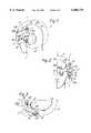
- Each of the optical sub-systems 17includes an objective lens 19 which, when in the operative position, is offset laterally and rearwardly with respect to its associated eyepiece 15 so as to occupy a position alongside the temple of the helmet wearer and substantially aligned in the helmet fore and aft directions with a side portion 21 of the helmet 11, i.e. a portion of the helmet 11 dependent from the upper, generally hemispherical, portion of the helmet enclosing the upper part of the helmet wearer's head 14.
Landscapes
- Physics & Mathematics (AREA)
- General Physics & Mathematics (AREA)
- Optics & Photonics (AREA)
- Telescopes (AREA)
- Measurement And Recording Of Electrical Phenomena And Electrical Characteristics Of The Living Body (AREA)
- Vehicle Step Arrangements And Article Storage (AREA)
- Medicines Containing Material From Animals Or Micro-Organisms (AREA)
Abstract
Description
Claims (19)
Applications Claiming Priority (4)
| Application Number | Priority Date | Filing Date | Title |
|---|---|---|---|
| GBGB8706943.1AGB8706943D0 (en) | 1987-03-24 | 1987-03-24 | Helmet systems |
| GB8706943 | 1987-03-24 | ||
| GB8718177 | 1987-07-31 | ||
| GBGB8718177.2AGB8718177D0 (en) | 1987-07-31 | 1987-07-31 | Helmet systems |
Publications (1)
| Publication Number | Publication Date |
|---|---|
| US6008779Atrue US6008779A (en) | 1999-12-28 |
Family
ID=26292051
Family Applications (1)
| Application Number | Title | Priority Date | Filing Date |
|---|---|---|---|
| US07/172,335Expired - Fee RelatedUS6008779A (en) | 1987-03-24 | 1988-03-10 | Night vision viewing systems |
Country Status (9)
| Country | Link |
|---|---|
| US (1) | US6008779A (en) |
| BE (1) | BE1011163A5 (en) |
| DE (1) | DE3809788C2 (en) |
| FR (1) | FR2748821B1 (en) |
| GB (1) | GB2316758B (en) |
| IT (1) | IT8867961A0 (en) |
| NL (1) | NL194808C (en) |
| NO (1) | NO881260L (en) |
| SE (1) | SE470596B (en) |
Cited By (12)
| Publication number | Priority date | Publication date | Assignee | Title |
|---|---|---|---|---|
| US6249386B1 (en)* | 1998-07-28 | 2001-06-19 | Elbit Systems Ltd. | Non-adjustable helmet mounted optical systems |
| USD472911S1 (en) | 2002-07-01 | 2003-04-08 | E. D. Bullard Company | Portable thermal imager |
| GB2416859A (en)* | 2004-08-03 | 2006-02-08 | Iain Chapman | Articulated light guide apparatus |
| US20070091448A1 (en)* | 2003-12-01 | 2007-04-26 | Andreas Durner | Electronic spectacles, in particular night vision spectacles |
| WO2007144465A1 (en)* | 2006-06-12 | 2007-12-21 | Patria Aviation Oy | Night vision arrangement |
| US20080266669A1 (en)* | 2005-05-30 | 2008-10-30 | Andreas Durner | Electronic Day and Night Vision Spectacles |
| US20100103267A1 (en)* | 2008-10-27 | 2010-04-29 | O'rourke Brian | Night vision system |
| US8184974B2 (en) | 2006-09-11 | 2012-05-22 | Lumexis Corporation | Fiber-to-the-seat (FTTS) fiber distribution system |
| US8416698B2 (en) | 2009-08-20 | 2013-04-09 | Lumexis Corporation | Serial networking fiber optic inflight entertainment system network configuration |
| US8424045B2 (en) | 2009-08-14 | 2013-04-16 | Lumexis Corporation | Video display unit docking assembly for fiber-to-the-screen inflight entertainment system |
| US20130155244A1 (en)* | 2008-10-27 | 2013-06-20 | Brian O'Rourke | Night vision system |
| US8659990B2 (en) | 2009-08-06 | 2014-02-25 | Lumexis Corporation | Serial networking fiber-to-the-seat inflight entertainment system |
Families Citing this family (1)
| Publication number | Priority date | Publication date | Assignee | Title |
|---|---|---|---|---|
| JP4095422B2 (en) | 2002-12-04 | 2008-06-04 | キヤノン株式会社 | Image display device and image display system |
Citations (14)
| Publication number | Priority date | Publication date | Assignee | Title |
|---|---|---|---|---|
| GB1527049A (en)* | 1976-06-18 | 1978-10-04 | Pilkington Perkin Elmer Ltd | Head-up displays |
| US4361384A (en)* | 1980-06-27 | 1982-11-30 | The United States Of America As Represented By The Secretary Of The Army | High luminance miniature display |
| GB2100466A (en)* | 1981-05-29 | 1982-12-22 | Marconi Avionics | Night vision goggles |
| EP0077193A2 (en)* | 1981-10-14 | 1983-04-20 | Gec Avionics Limited | Optical arrangements for Head-up Displays and Night Vision Goggles |
| US4439755A (en)* | 1981-06-04 | 1984-03-27 | Farrand Optical Co., Inc. | Head-up infinity display and pilot's sight |
| US4465347A (en)* | 1982-11-15 | 1984-08-14 | The United States Of America As Represented By The Secretary Of The Air Force | Helmet mounted telescope |
| GB2144558A (en)* | 1983-08-03 | 1985-03-06 | Marconi Avionics | Night vision viewing systems |
| WO1985004961A1 (en)* | 1984-04-16 | 1985-11-07 | Hughes Aircraft Company | Biocular holographic helmet mounted display |
| WO1986005281A1 (en)* | 1985-03-01 | 1986-09-12 | Fjw Industries, Inc. | Objective lens system, relay lens system, and eyepiece lens system for night-vision goggles |
| EP0206324A2 (en)* | 1985-06-27 | 1986-12-30 | Honeywell Inc. | Dual source display apparatus |
| EP0252200A1 (en)* | 1986-07-08 | 1988-01-13 | OIP OPTICS Naamloze Vennootschap | Night vision goggles |
| US4735473A (en)* | 1985-05-03 | 1988-04-05 | Thomson-Csf | Device for optical-cable transport and combination of light images |
| US4743200A (en)* | 1984-11-13 | 1988-05-10 | Cae Electronics, Ltd. | Fiber optic coupled helmet mounted display system |
| US4753514A (en)* | 1986-05-12 | 1988-06-28 | Iota Instrumentation Co. | Headwear-mounted periscopic display device |
Family Cites Families (1)
| Publication number | Priority date | Publication date | Assignee | Title |
|---|---|---|---|---|
| DE3171313D1 (en)* | 1980-08-26 | 1985-08-14 | Unilever Plc | Article and method for conditioning hair |
- 1988
- 1988-03-10USUS07/172,335patent/US6008779A/ennot_activeExpired - Fee Related
- 1988-03-18GBGB8806482Apatent/GB2316758B/ennot_activeExpired - Fee Related
- 1988-03-21NLNL8800694Apatent/NL194808C/ennot_activeIP Right Cessation
- 1988-03-22NONO881260Apatent/NO881260L/enunknown
- 1988-03-23SESE8801071Apatent/SE470596B/ennot_activeIP Right Cessation
- 1988-03-23DEDE3809788Apatent/DE3809788C2/ennot_activeExpired - Fee Related
- 1988-03-23FRFR8803825Apatent/FR2748821B1/ennot_activeExpired - Fee Related
- 1988-03-24BEBE8800336Apatent/BE1011163A5/ennot_activeIP Right Cessation
- 1988-10-26ITIT8867961Apatent/IT8867961A0/enunknown
Patent Citations (17)
| Publication number | Priority date | Publication date | Assignee | Title |
|---|---|---|---|---|
| GB1527049A (en)* | 1976-06-18 | 1978-10-04 | Pilkington Perkin Elmer Ltd | Head-up displays |
| US4361384A (en)* | 1980-06-27 | 1982-11-30 | The United States Of America As Represented By The Secretary Of The Army | High luminance miniature display |
| GB2100466A (en)* | 1981-05-29 | 1982-12-22 | Marconi Avionics | Night vision goggles |
| US4439755A (en)* | 1981-06-04 | 1984-03-27 | Farrand Optical Co., Inc. | Head-up infinity display and pilot's sight |
| EP0077193A2 (en)* | 1981-10-14 | 1983-04-20 | Gec Avionics Limited | Optical arrangements for Head-up Displays and Night Vision Goggles |
| GB2108702A (en)* | 1981-10-14 | 1983-05-18 | Marconi Avionics | Optical arrangements |
| US4465347A (en)* | 1982-11-15 | 1984-08-14 | The United States Of America As Represented By The Secretary Of The Air Force | Helmet mounted telescope |
| EP0134116A2 (en)* | 1983-08-03 | 1985-03-13 | Gec-Marconi Limited | Night vision viewing systems |
| GB2144558A (en)* | 1983-08-03 | 1985-03-06 | Marconi Avionics | Night vision viewing systems |
| US4563061A (en)* | 1983-08-03 | 1986-01-07 | Marconi Avionics Limited | Night vision viewing systems |
| WO1985004961A1 (en)* | 1984-04-16 | 1985-11-07 | Hughes Aircraft Company | Biocular holographic helmet mounted display |
| US4743200A (en)* | 1984-11-13 | 1988-05-10 | Cae Electronics, Ltd. | Fiber optic coupled helmet mounted display system |
| WO1986005281A1 (en)* | 1985-03-01 | 1986-09-12 | Fjw Industries, Inc. | Objective lens system, relay lens system, and eyepiece lens system for night-vision goggles |
| US4735473A (en)* | 1985-05-03 | 1988-04-05 | Thomson-Csf | Device for optical-cable transport and combination of light images |
| EP0206324A2 (en)* | 1985-06-27 | 1986-12-30 | Honeywell Inc. | Dual source display apparatus |
| US4753514A (en)* | 1986-05-12 | 1988-06-28 | Iota Instrumentation Co. | Headwear-mounted periscopic display device |
| EP0252200A1 (en)* | 1986-07-08 | 1988-01-13 | OIP OPTICS Naamloze Vennootschap | Night vision goggles |
Non-Patent Citations (4)
| Title |
|---|
| Cook, SPIE, vol. 193, Optical Systems Engineering, 1979, p. 153, 350 174.* |
| Cook, SPIE, vol. 193, Optical Systems Engineering, 1979, p. 153, 350-174. |
| Yoder, SPIE Journal, vol. 9, No. 1, Oct. Nov. 1970, p. 5.* |
| Yoder, SPIE Journal, vol. 9, No. 1, Oct.-Nov. 1970, p. 5. |
Cited By (20)
| Publication number | Priority date | Publication date | Assignee | Title |
|---|---|---|---|---|
| US6249386B1 (en)* | 1998-07-28 | 2001-06-19 | Elbit Systems Ltd. | Non-adjustable helmet mounted optical systems |
| USD472911S1 (en) | 2002-07-01 | 2003-04-08 | E. D. Bullard Company | Portable thermal imager |
| US20070091448A1 (en)* | 2003-12-01 | 2007-04-26 | Andreas Durner | Electronic spectacles, in particular night vision spectacles |
| US7576919B2 (en)* | 2003-12-01 | 2009-08-18 | Andreas Durner | Electronic spectacles, in particular night vision spectacles |
| GB2416859A (en)* | 2004-08-03 | 2006-02-08 | Iain Chapman | Articulated light guide apparatus |
| US20080266669A1 (en)* | 2005-05-30 | 2008-10-30 | Andreas Durner | Electronic Day and Night Vision Spectacles |
| US7786424B2 (en) | 2005-05-30 | 2010-08-31 | Andreas Durner | Electronic day and night vision goggles having dual camera |
| WO2007144465A1 (en)* | 2006-06-12 | 2007-12-21 | Patria Aviation Oy | Night vision arrangement |
| US8184974B2 (en) | 2006-09-11 | 2012-05-22 | Lumexis Corporation | Fiber-to-the-seat (FTTS) fiber distribution system |
| US8400510B2 (en)* | 2008-10-27 | 2013-03-19 | Devcar, Llc | Night vision system |
| US20100103267A1 (en)* | 2008-10-27 | 2010-04-29 | O'rourke Brian | Night vision system |
| US20130155244A1 (en)* | 2008-10-27 | 2013-06-20 | Brian O'Rourke | Night vision system |
| US8773537B2 (en)* | 2008-10-27 | 2014-07-08 | Devcar, Llc | Night vision system |
| US8659990B2 (en) | 2009-08-06 | 2014-02-25 | Lumexis Corporation | Serial networking fiber-to-the-seat inflight entertainment system |
| US9118547B2 (en) | 2009-08-06 | 2015-08-25 | Lumexis Corporation | Serial networking fiber-to-the-seat inflight entertainment system |
| US9532082B2 (en) | 2009-08-06 | 2016-12-27 | Lumexis Corporation | Serial networking fiber-to-the-seat inflight entertainment system |
| US8424045B2 (en) | 2009-08-14 | 2013-04-16 | Lumexis Corporation | Video display unit docking assembly for fiber-to-the-screen inflight entertainment system |
| US8416698B2 (en) | 2009-08-20 | 2013-04-09 | Lumexis Corporation | Serial networking fiber optic inflight entertainment system network configuration |
| US9036487B2 (en) | 2009-08-20 | 2015-05-19 | Lumexis Corporation | Serial networking fiber optic inflight entertainment system network configuration |
| US9344351B2 (en) | 2009-08-20 | 2016-05-17 | Lumexis Corporation | Inflight entertainment system network configurations |
Also Published As
| Publication number | Publication date |
|---|---|
| SE8801071D0 (en) | 1988-03-23 |
| NL8800694A (en) | 2001-05-01 |
| FR2748821A1 (en) | 1997-11-21 |
| BE1011163A5 (en) | 1999-06-01 |
| DE3809788A1 (en) | 1998-01-08 |
| SE470596B (en) | 1998-03-16 |
| GB2316758A (en) | 1998-03-04 |
| GB2316758B (en) | 1998-07-01 |
| SE8801071L (en) | 1997-12-09 |
| IT8867961A0 (en) | 1988-10-26 |
| DE3809788C2 (en) | 2000-09-07 |
| NL194808B (en) | 2002-11-01 |
| GB8806482D0 (en) | 1997-07-16 |
| FR2748821B1 (en) | 1999-02-19 |
| NO881260L (en) | 1998-06-12 |
| NL194808C (en) | 2003-03-04 |
Similar Documents
| Publication | Publication Date | Title |
|---|---|---|
| US4828378A (en) | Night vision viewing systems | |
| US4563061A (en) | Night vision viewing systems | |
| US5035474A (en) | Biocular holographic helmet mounted display | |
| US4026641A (en) | Toric reflector display | |
| US4761056A (en) | Compact helmet mounted display | |
| US5079416A (en) | Compact see-through night vision goggles | |
| KR100277557B1 (en) | Low cost, low head mounted virtual projection display with low moment of inertia and low center of gravity | |
| US4969714A (en) | Helmet mounted display having dual interchangeable optical eyepieces | |
| US4775217A (en) | Night vision viewing system | |
| EP0583116B1 (en) | Display system | |
| US5880888A (en) | Helmet mounted display system | |
| US4961626A (en) | Direct incorporation of night vision in a helmet mounted display | |
| EP0834097B1 (en) | Head gear display system | |
| US5000544A (en) | Helmet system with optical display projection system including a cylindrical refractive surface | |
| EP0179124B1 (en) | Binocular holographic helmet mounted display | |
| US6008779A (en) | Night vision viewing systems | |
| JPH09304728A (en) | Optical sight device | |
| US5838490A (en) | Head mounted display system using mangin mirror combiner | |
| JPH03501173A (en) | heads-up display device | |
| NO333706B1 (en) | Night vision device | |
| GB2279153A (en) | Night vision system | |
| WO2000014585A1 (en) | Display system |
Legal Events
| Date | Code | Title | Description |
|---|---|---|---|
| AS | Assignment | Owner name:GEC-MARCONI LIMITED, THE GROVE, WARREN LANE, STANM Free format text:ASSIGNMENT OF ASSIGNORS INTEREST.;ASSIGNOR:ELLIS, STAFFORD M.;REEL/FRAME:004903/0031 Effective date:19880601 Owner name:GEC-MARCONI LIMITED, THE, A BRITISH COMPANY, ENGLA Free format text:ASSIGNMENT OF ASSIGNORS INTEREST;ASSIGNOR:ELLIS, STAFFORD M.;REEL/FRAME:004903/0031 Effective date:19880601 | |
| AS | Assignment | Owner name:GEC-MARCONI LIMITED Free format text:ASSIGNMENT OF ASSIGNORS INTEREST;ASSIGNOR:GEC-MARCONI (HOLDINGS) LIMITED;REEL/FRAME:006627/0425 Effective date:19930526 | |
| AS | Assignment | Owner name:BAE SYSTEMS ELECTRONICS LIMITED, UNITED KINGDOM Free format text:ASSIGNMENT OF ASSIGNORS INTEREST;ASSIGNOR:MARCONI (HOLDINGS) LIMITED;REEL/FRAME:013221/0417 Effective date:20020423 Owner name:MARCONI (HOLDINGS) LIMITED, UNITED KINGDOM Free format text:CHANGE OF NAME;ASSIGNOR:GEC-MARCONI LIMITED;REEL/FRAME:013221/0412 Effective date:20011209 | |
| FPAY | Fee payment | Year of fee payment:4 | |
| AS | Assignment | Owner name:BAE SYSTEMS PLC, UNITED KINGDOM Free format text:ASSIGNMENT OF ASSIGNORS INTEREST;ASSIGNOR:BAE SYSTEMS ELECTRONICS LIMITED;REEL/FRAME:017730/0039 Effective date:20050831 | |
| FEPP | Fee payment procedure | Free format text:PAYOR NUMBER ASSIGNED (ORIGINAL EVENT CODE: ASPN); ENTITY STATUS OF PATENT OWNER: LARGE ENTITY | |
| FPAY | Fee payment | Year of fee payment:8 | |
| FEPP | Fee payment procedure | Free format text:PAYOR NUMBER ASSIGNED (ORIGINAL EVENT CODE: ASPN); ENTITY STATUS OF PATENT OWNER: LARGE ENTITY Free format text:PAYER NUMBER DE-ASSIGNED (ORIGINAL EVENT CODE: RMPN); ENTITY STATUS OF PATENT OWNER: LARGE ENTITY | |
| REMI | Maintenance fee reminder mailed | ||
| LAPS | Lapse for failure to pay maintenance fees | ||
| STCH | Information on status: patent discontinuation | Free format text:PATENT EXPIRED DUE TO NONPAYMENT OF MAINTENANCE FEES UNDER 37 CFR 1.362 | |
| FP | Lapsed due to failure to pay maintenance fee | Effective date:20111228 |