US6008727A - Selectively enabled electronic tags - Google Patents
Selectively enabled electronic tagsDownload PDFInfo
- Publication number
- US6008727A US6008727AUS09/150,882US15088298AUS6008727AUS 6008727 AUS6008727 AUS 6008727AUS 15088298 AUS15088298 AUS 15088298AUS 6008727 AUS6008727 AUS 6008727A
- Authority
- US
- United States
- Prior art keywords
- tag
- identification number
- electronic tag
- electronic
- processor
- Prior art date
- Legal status (The legal status is an assumption and is not a legal conclusion. Google has not performed a legal analysis and makes no representation as to the accuracy of the status listed.)
- Expired - Lifetime
Links
Images


Classifications
- G—PHYSICS
- G06—COMPUTING OR CALCULATING; COUNTING
- G06K—GRAPHICAL DATA READING; PRESENTATION OF DATA; RECORD CARRIERS; HANDLING RECORD CARRIERS
- G06K7/00—Methods or arrangements for sensing record carriers, e.g. for reading patterns
- G06K7/10—Methods or arrangements for sensing record carriers, e.g. for reading patterns by electromagnetic radiation, e.g. optical sensing; by corpuscular radiation
- G06K7/10009—Methods or arrangements for sensing record carriers, e.g. for reading patterns by electromagnetic radiation, e.g. optical sensing; by corpuscular radiation sensing by radiation using wavelengths larger than 0.1 mm, e.g. radio-waves or microwaves
- G06K7/10019—Methods or arrangements for sensing record carriers, e.g. for reading patterns by electromagnetic radiation, e.g. optical sensing; by corpuscular radiation sensing by radiation using wavelengths larger than 0.1 mm, e.g. radio-waves or microwaves resolving collision on the communication channels between simultaneously or concurrently interrogated record carriers.
- G06K7/10079—Methods or arrangements for sensing record carriers, e.g. for reading patterns by electromagnetic radiation, e.g. optical sensing; by corpuscular radiation sensing by radiation using wavelengths larger than 0.1 mm, e.g. radio-waves or microwaves resolving collision on the communication channels between simultaneously or concurrently interrogated record carriers. the collision being resolved in the spatial domain, e.g. temporary shields for blindfolding the interrogator in specific directions
- G—PHYSICS
- G06—COMPUTING OR CALCULATING; COUNTING
- G06K—GRAPHICAL DATA READING; PRESENTATION OF DATA; RECORD CARRIERS; HANDLING RECORD CARRIERS
- G06K19/00—Record carriers for use with machines and with at least a part designed to carry digital markings
- G06K19/06—Record carriers for use with machines and with at least a part designed to carry digital markings characterised by the kind of the digital marking, e.g. shape, nature, code
- G06K19/067—Record carriers with conductive marks, printed circuits or semiconductor circuit elements, e.g. credit or identity cards also with resonating or responding marks without active components
- G06K19/07—Record carriers with conductive marks, printed circuits or semiconductor circuit elements, e.g. credit or identity cards also with resonating or responding marks without active components with integrated circuit chips
- G06K19/0723—Record carriers with conductive marks, printed circuits or semiconductor circuit elements, e.g. credit or identity cards also with resonating or responding marks without active components with integrated circuit chips the record carrier comprising an arrangement for non-contact communication, e.g. wireless communication circuits on transponder cards, non-contact smart cards or RFIDs
- G—PHYSICS
- G06—COMPUTING OR CALCULATING; COUNTING
- G06K—GRAPHICAL DATA READING; PRESENTATION OF DATA; RECORD CARRIERS; HANDLING RECORD CARRIERS
- G06K7/00—Methods or arrangements for sensing record carriers, e.g. for reading patterns
- G06K7/0008—General problems related to the reading of electronic memory record carriers, independent of its reading method, e.g. power transfer
Definitions
- the present inventionrelates to a system for transferring electronic information using multiple electronic tags. More particularly, the present invention relates to object attachable radiofrequency electronic tags and tag readers connected to a computer network.
- Tagging items with barcodes or symbols that facilitate optical character recognitionhas long been used to identify and track product inventories, baggage, paper checks, or other movable items susceptible to misplacement or loss.
- optically perceptible tagsmust remain visible for identification, and can be easily rendered unreadable by surface marks or other damage.
- tagstypically have a semiconductor memory for data storage, processing logic, and a small antenna for broadcasting data, all embedded in rugged epoxy, thermoplastic, or other suitable plastic containers. Data storage capacity typically ranges from a few bits to many kilobits, with 64 bits being typical.
- Tagscan include read only memory (ROM), electrically programmable or erasable (EPROM and EEPROM), or even flash memory.
- ROMread only memory
- EPROM and EEPROMelectrically programmable or erasable
- An electronic tagcan be powered by a long lasting small battery, photovoltaic power, thermal convertor, inductive power converter that relies on externally applied electromagnetic energy, or any other suitable power supply.
- an electronic tagis attached to a physical document
- a usercan access some associated virtual representation (e.g. an ASCII text file) by placing it near an augmented computer equipped with a tag reader.
- the resulting systemis a powerful tool for maintaining a bridge between physical and virtual representations of documents, or, in general, for augmenting physical objects with virtual associations.
- the present systemcan be used to track multiple tagged documents in close proximity, or to allow performance of various selected services (e.g. printing, e-mailing, discarding electronic copies, opening electronic applications)
- the present inventionmeets these requirements by providing a system for identifying multiple electronic tags that includes a plurality of electronic tags attachable to a single object, each electronic tag having a non-overlapping readable region, and each electronic tag having a unique identifier.
- One or more electronic tag readersare configured to read the unique identifier of each electronic tag within the non-overlapping readable region, and a computing system is connected to the electronic tag reader to provide digital services in response to reading the unique identifier of each electronic tag.
- the electronic tagscan have integral sensor systems that detect, for example, light, location, acceleration, or other physical properties, allowing provision of particular digital services related to the sensed properties.
- Such a systemis particularly useful for multiple tagging of substantially three-dimensional objects (solids) or two-dimensional objects (sheets) with large numbers of distinct electronic tags.
- a multifaced solidsuch as a polygon can have each face, edge, or vertex equipped with a unique electronic tag that invokes a s digital service (or provides parameters for enabled digital services).
- Various symbolic indiciasuch as text, graphics (pictures or line drawings), color codings, texture codings, etc. can be used to assist a user in associating a particular tag with a digital service.
- the foregoing electronic tagscan be read by tag readers attached to desktop computers, or in certain embodiments, by tag readers integral or closely attached to portable or hand holdable computers.
- portable computerscan also support wireless network transceivers for communication with a computer network, extending the range of supported digital services.
- At least one electronic identification tagis affixed to each physical item that is associated with digital services.
- These tagscan be small radio frequency transponders comprised of an integrated circuit, containing a unique user accessible 39-bit identification number.
- a small coilinductively powers the tag, and an antenna is used to broadcast the identification number.
- the antennacan be separate from the coil, or alternatively, a dual-use inductive power coil/antenna coil can be used.
- a tag readerthat includes transmitter and receiver components is affixed to a computational device such as a hand held computer.
- the tag readertransmits a pulse that momentarily energizes the tag through its coil until it has sufficient power for transient transmission of its identification number.
- the communication between tag and tag readeronly occurs when both are proximate, with an actual distance varying based on size of the antenna attached to the tag and to the transmitter, from a distance of a few inches to that of several feet.
- the tag readerpasses this on to the computer system as an ASCII string, via a serial RS-232 output or some other suitable connection, while simultaneously providing user feedback to confirm reading of the tag.
- User feedbackcan be visual (e.g. blinking or turning on an LED status light, text based or iconic display presentations), auditory (e.g. an audible buzz or beep), tactile (e.g. a button being raised or a perceptible structure rotation), or combinations of the foregoing.
- a computer based application programUpon receipt of the identification number, a computer based application program interprets the identification input string, determines the current application context, and provides appropriate digital services. For example, an ASCII database that maps identification numbers to one or more digital services can be used. One common action is a ⁇ program, identification number ⁇ pair that invokes the identified program on the associated identification number. If the received identification number has not been previously registered, i.e. associated with an action in the ASCII database, the user can be prompted to enter an action(s) and any associated parameters via a dialog box. Network and server connectivity is provided by a separate wireless radiofrequency or infrared networking system. If the program or the file to be retrieved reside on the network, filenames that are independent of the particular sensing computer can be used.
- tags in accordance with the present inventioncan convey small amounts of modifiable data (maintained, e.g., in flash memory).
- data provided by sensors embedded or attached to the tagcan be used to detect folding, twisting, or bending of the tagged object.
- a number of accelerometers that sense relative spatial information; gyroscopic, radio or infrared positional sensors for determining absolute position; and various thermal or photosensors that respectively detect temperature and light level changescan provide sensed data values for later transmission by the tag.
- Intentional or unintentional modifications detected by one or more of these sensor systems, taken in conjunction with the particular tag presented to the tag reader,can provide the basis for a powerful user interface scheme.
- each identification number or sensed data value that is read (sensed) by the tagcan be labeled as a "senseme", with a particular digital service or attribute being associated with each senseme.
- the wide variety of easily distinguishable sensemese.g. identification numbers
- the present inventionfurther extends the flexibility of the senseme based user interface by supporting computer control based on a multiple senseme input, with temporally synchronous (or overlapping asynchronous) tuples of one or more sensemes (e.g. particular identification numbers and sensed states) being read by the tag reader.
- Single and multiple sensemescan in turn be extended by participation in a "sentence".
- a sentenceis defined as a sequence of one or more temporally disjoint sensemes or senseme tuples.
- the sentence levelallows definition of a input grammar by appropriate choice of senseme sequence, and corollary rules governing, for example, use of active verb-like sensemes (e.g. "print"), naming noun-like sensemes (e.g. DOC1.TXT), or connectors (e.g. AND).
- active verb-like sensemese.g. "print”
- naming noun-like sensemese.g. DOC1.TXT
- connectorse.g. AND
- the present inventionprovides a method for transferring information from a tagged object with optional sensors to a tag reader connected computer.
- the methodcomprises the steps of manipulating one or more tags and optional tag sensors to provide a first senseme input (that includes the tag identification number) to the computer, with the first senseme input normally triggering a first default action by the computer.
- the tagged objectmay also be manipulated to provide a second senseme input (again including a tag identification number) to the computer, with the second senseme input converting the normally triggered first default action to a second action.
- the first and second sensemestogether form a sentence that can be interpreted as a command to implement a computer controlled action, whether it be to open and print a particular electronic document, unlock an electronically controlled door in response to a tag conveyed personal identification number, display a graphical image on a computer display, or begin logging on to a computer network.
- the sentence "establish authorization, open a file, and print the file to printer number 3"can involve the sequential steps of reading a first tag embedded in a picture identification card to establish user identification, immediately presenting a second tag clipped to a paper document to specify a related electronic document and finally presenting a three dimensional token that appears like a small printer with an embedded third tag and pressure sensor that initiates printing of the previously specified document at printer number 3 after pressure sensors electrically connected to the tag are squeezed three times.
- the foregoing operationconveniently distinguishes particular electronic documents, and allows a user to select particular printers, (e.g. with printer 1 requiring one sensed squeeze and printer 2 requiring two sensed squeezes) without requiring visual displays or complex input commands.
- an electronic tagincluding a processor, a readable memory for holding an identification number connected to the processor, an antenna connected to the processor for radiofrequency broadcasting of the identification number, and a power supply for powering the antenna to broadcast the identification number is provided with an electromagnetic shield positioned near the antenna for reducing broadcasting range of the antenna.
- the shieldcan, for example, be metallic wire or sheeting positioned at least partially around or near the antenna, or metal lined cavities into which the electronic tag is attached.
- Such shields in accordance with the present inventionreduce reading range and can limit reading of the tag to specific directions.
- electronic tagscan be partially surrounded with shields to limit readable electromagnetic radiation to a direction substantially normal to the surface of an object to which the tag is attached.
- Such shieldswould allow large numbers of electronic tags to be closely spaced on an object, since interfering lateral electromagnetic radiation from adjacent tags would be inhibited.
- the electromagnetic shieldis movable between a first substantially non-blocking position and a second blocking position that respectively unblocks and blocks antenna broadcast.
- the movable electromagnetic shieldcan be s biased to remain in its first substantially non-blocking position to allow antenna broadcast, or alternatively biased to remain in its second blocking position to block antenna broadcast.
- a user movable shieldalso permits use of the electronic tag as a user defined communication channel for transmitting small amounts of information.
- an electronic tag having a transmitted identification numberis controllably shielding and deshielding to provide a user defined time series of readable and non-readable intervals for the transmitted identification number
- the consequent user defined time series of readable and non-readable intervals for the transmitted identification numbercan be interpreted as bit-wise communication associatable with the transmitted identification number.
- a usercould send bit codes by intermittently interrupting reading of the electronic tag (or alternatively, by intermittently allowing reading of the electronic tag).
- Such small amounts of user defined and transmitted informationcan be used to parameterize digital services associated with the transmitted identification number, or can even be used as personal identification numbers or verifiers to initiate triggering of a digital service in response to reading an electronic tag.
- a tag readercan be configured to launch an application only after receipt of two pulses (clicks) of a particular identification number.
- Such a mechanismreduces inadvertent or unwanted triggering of a digital service ordinarily provided in response to reading an electronic tag.
- An electronic taghaving a processor, a readable memory for holding an identification number connected to the processor, an antenna connected to the processor for radiofrequency broadcasting of the identification number, a power supply for powering the antenna to broadcast the identification number, is also provided with an interconnect switch for interconnecting at least two members selected from a set defined by the processor, readable memory, antenna, and power supply.
- the interconnect switchcan be biased to remain normally open, preventing broadcast of the identification number, or alternatively, can be biased to remain normally closed, allowing broadcast of the identification number.
- the interconnect switchcan be connected between the antenna and one of the processor and the power supply, with opening or closure being controlled by a user that opens or closes electrical contacts in the interconnect switch (using any conventional button, contact switch, electrical switch, or other conventional switch known to those skilled in the art).
- a sensorcan be connected to the processor, and the interconnect switch is alternately opened and closed in response sensor data provided by the sensor.
- an electronic tagcan be equipped with an accelerometer capable of signaling when the tag is nudged or shaken. Normally, the tag remains disabled with its interconnect switch open.
- the accelerometersenses the transient accelerations and sends a signal to the interconnect switch to close, allowing the electronic tag to broadcast its identification number.
- a second shakingreverses the foregoing, causing the sensor to signal the interconnect switch to open and break the antenna/power-supply connection (for example), disabling the electronic tag.
- Sensor systems responding to heat, light, sound, force, or any suitable effectcan be employed in the present invention.
- user defined enablement or disablement of the electronic tagscan be used for low bit rate communications directed by a user.
- Controllably switching an interconnect switch of an electronic tag having a transmittable identification numberprovides a user defined time series of readable and non-readable intervals for the transmitted identification number.
- This user defined time series of readable and non-readable interval for the transmitted identification numbercan be readily interpreted as bit-wise communication associatable with the transmitted identification number.
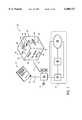
- FIG. 1is a schematic diagram of a system for identifying multiple electronic tags and providing various digital services in response to sequential presentation of electronic tags to an electronic tag reader;
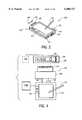
- FIG. 2is an illustration of a hand holdable computer having an attached electronic tag reader
- FIG. 3is a schematic illustration showing various components of a conjoined hand holdable computer and attached electronic tag reader such as shown in FIG. 2;
- FIG. 4is a schematic illustration of a user employing a conjoined hand holdable computer and attached electronic tag reader such as shown in FIG. 2 to access an identification number of an electronic tag affixed to a two dimensional wall mounted poster, and wirelessly transfer that information to a computer network for accessing related electronic documents;
- FIG. 5illustrates a networked printer capable of printing documents identified by an electronic tag, and of associating newly printed documents with a unique electronic tag dispensed or attached by the printer;
- FIGS. 6 and 7 taken togetherare a flow chart that together illustrates various steps in interpreting signals from electronic tags and launching appropriate digital services
- FIG. 8is an exemplary illustration of a movable disk shaped shield rotatable relative to a disk having several attached electronic tags
- FIG. 9is an example of a slidable shield
- FIGS. 10, 11, and 12are an example of a clickable shield that can be used to send low bit rate user information by selective shielding and deshielding of an electronic tag;
- FIG. 13is a schematic illustration of elements of an electronic tag controllably interconnected by an interconnect module to allow selective enablement or disablement of the electronic tag;
- FIG. 14is an example of a selectively enabled electronic tag, with a processor/memory unit normally biased to be separated from power converter antenna unit;
- FIG. 15is a graph schematically illustrating a user defined bit signaling time series of readable and non-readable intervals for a transmitted identification number from an electronic tag.
- FIG. 1is a schematic diagram of a system 10 for identifying multiple electronic tags 32, 42, 44, and 46 (each tag generally having a unique electronically readable identification number) and providing various digital services in response to presentation of those electronic tags to electronic tag readers 20, 26, or 28.
- the electronic tag reader 20(or electronic tag reader 26 and 28) is connected to a computer system 12, which further includes a local computer 14, database servers 16, and networked computers 18.
- electronic tag 32is clipped to a paper document 30, while electronic tags 42, 44, and 46 are mounted respectively on faces 52, 54, and 56 of a cube shaped polygon 50.
- Determining what digital service is invokedis aided by various textual, graphical, or symbolic indicators 62, 64, and 66 respectively located near each electronic tag 42, 44, and 46.
- the electronic Is tags 32 or 42, 44, and 46are brought near one or more of the tag readers, query/response signals 22 and 24 are passed between the electronic tags and the tag reader, and the identification number of the read electronic tag is passed to the computer system.
- electronic tagscan be attached permanently or temporarily to various objects, including but not limited to the paper document 30, polygon 50, books, magazines, posters, notecards, printed advertisements, walls, floors, ceilings, furniture, electronic devices, portable computers, containers, cardboard boxes, clothing, or any other suitable object.
- Electronic tagscan be permanently attached by embedment in objects, adhesive attachment to an object's surface, fixation by staples, or by mating to an object by any other suitable attachment mechanism.
- Temporary fixation of electronic tags to objectscan be enabled through the use of object attachable clips, snaps, or ties (e.g. a paper clip with attached electronic tag, a rubber band or loop of string with an attached electronic tag), simple resting dispersal (e.g. throwing an electronic tag to rest upon a floor), insertion into a slot or receptacle, or any other suitable temporary attachment mechanism that advantageously eases reuse of an electronic tag by allowing successive association with various attached objects.
- an object having more than one attached tagis indicated as polygon 50.
- the polygon 50has multiple electronic tags 42, 44, and 46, one respectively mounted on each face 52, 54, and 56.
- the polygon 50can be rotated to substantially present one face and its corresponding face center mounted electronic tag to the reader 20.
- electronic tagscan be mounted anywhere on the polygon 50, including on its edges, on its vertices, in a random or semirandom distribution, or symmetrically distributed about the polygon and centered on each face, as illustrated.
- use of such polygonse.g.
- cubes, tetrahedrons, rhombic dodecahedrons, two sided planar solids, or related shapes), in conjunction with face centered attachment,can take advantage of passive shielding of the faces to limit simultaneous readings of multiple electronic tags.
- the polygon 50is indicated as a unitary solid object, various other shapes are contemplated to be within the scope of the present invention.
- the overall shapemay be similar to various rectangular prisms, or can be spheroidal, ellipsoidal, toroidal, planar, irregular, or even malleable enough to allow user definition of object shape.
- multiple cooperating shape elements fitted with electronic tagsare contemplated, including conventional designs that permit interlocking of multiple shape elements, using ball and socket, a lock and key, slidable or rotatable interlocked components, chains, or any other linked object.
- Electronic tags suitable for attachment to such foregoing objects in accordance with the present inventiongenerally broadcast a unique identification number and optional data at various selected radiofrequencies.
- the identification numbercan be user assigned at electronic tag activation, user modifiable by software command, or fixed by an electronic tag manufacturer, depending on the particular memory system employed.
- infrared, ultrasonic, or other suitable data transfer systemsmay be used alone or in combination with radiofrequency tags to transmit unique identification numbers or associated data.
- the electronic tagscan be inductively powered by external electromagnetic coils, powered by internal batteries, powered by photovoltaic cells, powered by trickle currents from household current when available, or any other suitable power mechanism. Broadcast of the identification number and/or data can be continuous, intermittent, in response to external status inquiries, at random intervals, or in response to local powering of the electronic tag.
- the electronic tag 46can be optionally attached to a sensor 47.
- Various sensor modescan supported, including absolute or relative positional information as determined by gyroscopic sensors, accelerometers, or acoustic or infrared ranging techniques.
- Environmental sensorsincluding conventional light, image, thermal, electromagnetic, vibratory, or acoustic sensors can also be present.
- environmental or positional sensorssuch as those incorporating differential GPS positioning, image analysis or recognition, acoustic or voice identification, or differential thermal sensors can be used.
- Sensorsmay include accelerometers, compressional or tensional strain sensors, or alternatively, embedded or attached positional sensors.
- continuous sensorse.g. bilayer sheets of capacitance sensors
- One particularly useful continuous sensor typeuses multiple capacitance or resistance strips, with deformation pressure resulting in a positionally localizable analog signal proportional to the applied deformation pressure.
- Various sensor typescan be used, including simple capacitance sensors, resistive strain sensors, analog or digital pressure switches, inductive sensors, or even fluid flow sensors.
- sensor datacan be directly fed to the electronic tag 46 in digital form, or be transformed to digital format by an general purpose analog/digital converter that typically provides a 4 or 8 bit range (although as few as one or as many as 32 bits may be required by various applications).
- use of such sensor systemsprovides additional input information that can form part of a user interface system enabled in part by electronic tags.
- various feedback displayscan be attached to electronic tags 46.
- electronic tag activation and operationmay be indicated by appropriate user feedback from devices positioned either near the electronic tag 46 or near the electronic tag reader 20.
- LED status light 49 near the electronic tag 46 and LED status light 21 near the electronic tag reader 20can be set to provide an intermittent or steady visually perceptible light when the electronic tag is actively transmitting to the electronic tag reader 20, providing visual confirmation to a user of data transfer.
- a conventional passive or active matrix liquid crystal displaysuch as commonly used in hand holdable computers, or a display based on various electro optical or micromechanical techniques can be used.
- a non-imaging displaysuch as may be formed by localized or distributed chromatic changes in a suitable electrochromic materials may be used to provide visual feedback to the user.
- visual outputmay be augmented (or even replaced) with a non-visual display.
- the non-visual displaycan include tactile displays based on internal actuators or auditory feedback.
- one possible feedback displayis based on internal auditory speakers (emitting a range of sounds from simple "beeps" to well formed speech, depending on available processor speed and functionality) for providing user feedback.
- a non-visual display and its associated actuators or electronicscan support alternative feedback modes, including, for example, force feedback to a user through internal actuators, tactile based feedback (e.g. with multiple surface projections for presentation of Braille or other conventional tactile user interface), modifications to the surface texture of the device, or any other conventional mechanism for supplying status information to a user.
- the tag reader 20(and tag readers 26 and 28) can be constructed to detect electromagnetic, optical, or acoustic signals at various frequencies.
- the tag reader 20can write as well as read electronic tag identification numbers and data. It will be understood that the particular digital service invoked in response to reading a tag can depend on which tag reader 20, 26, or 28 reads the tag, the order in which electronic tags are read by one or more of the electronic tag reader, the duration of presentation of an electronic tag to a particular reader, or any other suitable user understandable electronic tag reading protocol.
- the computer system 12is used to interpret the identification number of the electronic tag and provide the requested digital service. Semantic binding of the identification number can be provided by a computer 14 (which can be a desktop computer, a dedicated electronic tag processor, or a hand holdable pen computer), by networked connected database servers 16, or by other accessible networked computers 18.
- a computer 14which can be a desktop computer, a dedicated electronic tag processor, or a hand holdable pen computer
- networked connected database servers 16or by other accessible networked computers 18.
- Computers in computer system 12can be interconnected by various hard wired or wireless connections, and may support various communication protocols and designs, including use of a serial tethered (using, for example the RS-232C interface protocols), use of infrared signals adhering to widely utilized IRDA communication standards, or use of radiofrequency signals (which can be, for example, a cellular telephone, 900 MHz radio, or digital PCS telephonic communications).
- a serial tetheredusing, for example the RS-232C interface protocols
- infrared signals adhering to widely utilized IRDA communication standardsor use of radiofrequency signals (which can be, for example, a cellular telephone, 900 MHz radio, or digital PCS telephonic communications).
- radiofrequency signalswhich can be, for example, a cellular telephone, 900 MHz radio, or digital PCS telephonic communications.
- Alternative communication standards, or even alternative communication carrierssuch as those based on optical or acoustic techniques, can of course be employed.
- Binding digital services to particular electronic tagscan be user defined, provided as default bindings by a system provider, learned by the system through repetition or context, or some combination of these and other suitable semantic binding techniques.
- a database formatcan be constructed in which each identification number of an electronic tag is a database key. Associated with that key is a set of digital actions to undertake when that identification number of an electronic tag is detected. There is an enumerated list of such actions--display a Web page, display a text document, display a date in a calendar, go to a certain location in a document, and so forth. Each action is parameterized by a list of (name, value) pairs appropriate for that action.
- the action to display a text documenthas pairs associated with it indicating the file to display, whether it should display in read-only mode, or whether the file should be converted to a particular format.
- this general (name, value) mechanismand having the database be in human-readable ASCII form, a user can easily add new tags and new types of actions to an initially provided list. Since the database is editable, associations between identification numbers of electronic tags and digital services can be modified at any time by a user.
- the user interface of the present inventioncan be extended by sequentially or simultaneously reading multiple electronic tags from one or more tag readers.
- each identification number or sensed data value that is read (sensed) by the tagcan be labeled as a "senseme", with a particular digital service or attribute being associated with each senseme.
- the present inventionfurther extends the flexibility of the senseme based user interface by supporting computer control based on a multiple senseme input, with temporally synchronous (or overlapping asynchronous) tuples of one or more sensemes (e.g.
- a sentenceis defined as a sequence of one or more temporally disjoint sensemes or senseme tuples.
- the sentence levelallows definition of a input grammar by appropriate choice of senseme sequence, and corollary rules governing, for example, use of active verb-like sensemes or naming noun-like sensemes.
- the verb "print”is associated with tag 42, the textual lettering "PRINT” and the symbolic icon of a printer 62 on the polygon 50, while the noun "http://www.test.com/DOC1.TXT”, is associated with a URL to an electronic copy of a document corresponding to the printed document 30.
- contextcan affect how sensemes are interpreted. For example, a small model of a printer with a tag on it can produce a senseme interpretable as either the verb "print” or the noun “printer” depending on its surrounding sensemes.
- sensemes taken togetherform a sentence that can be interpreted as a command to implement a computer controlled action (i.e. digital service), whether it be to open and print a particular electronic document, unlock an electronically controlled door in response to a tag conveyed personal identification number, display a graphical image on a computer display, or begin logging on to a computer network.
- a computer controlled actioni.e. digital service
- the sentence "establish authorization, open a file, and print the file to printer number 3"can involve the sequential steps of reading a electronic tag 46 to establish user identification, immediately presenting an electronic tag 32 clipped to a paper document 30 to specify a related electronic document (i.e.
- some temporally distinguishable sensemesfurther represent sensemes used as a basis for a grammar in accordance with the present invention.
- All of the following described sensemescan be modified by numerous variations in identity of electronic tag (e.g. tag number 237654 vs. 124934), class of electronic tag (e.g. the 1000 series versus the 4000 series), presentation of sequence of particular electronic tags, repetition or timing variations in tag presentation or sequencing, as well as sensor input such as positional information, applied pressure, force utilized in squeezing a pressure sensor.
- timing of various objectscan modify interpretation of a senseme.
- squeezeis taken as a typical senseme supplied by a pressure sensor 45, one can appreciate various squeeze operations such as quick squeeze, slow squeeze, hard squeeze, soft squeeze, narrow squeeze, or wide squeeze.
- squeeze sensemeswould be considered members of the "squeeze” class, with individual variations acting as possible modifiers to electronic tag identification number and its default semantic binding.
- FIG. 2is an illustration of a tag reading system 100 for reading an electronic tag 150 with optional connected sensor 160.
- the system 100includes a hand holdable pen computer 110 with input/output aided by pen 112 and touch sensitive display surface 114, wireless infrared or radiofrequency port 140 for communication with a network (not shown), and an attached electronic tag reader 120.
- the tag reader 120is powered by line 132 to pen computer 110, and serial communications with pen 110 are maintained by serial connection 130 (e.g. an RS-232C connection).
- serial connection 130e.g. an RS-232C connection
- FIG. 3is a schematic illustration of the tag reading system 100 of FIG. 2.
- the electronic tag 150includes memory 152 for holding an identification number, other user or system defined data, and optionally any sensor data from sensor 160.
- a processor 154 connected to the memory 152handles onboard logic, including optional data preprocessing, power control, and transmission/reception tasks. It will be understood that the processor 154 may include only a few logical elements, or can be a full featured microprocessor with memory 152 on the microprocessor chip.
- a power supply 156e.g. a battery, an inductive power converter, photovoltaic cells, etc.
- the tag reader 120includes tag-reader-processor/memory-buffer 120, and electromagnetic reading coil 122.
- Trovanan electronic tag reading system similar to that illustrated in conjunction with FIGS. 2 and 3
- a Trovan tagconsists of a small coil and a tiny microchip connected to the coil, collapsing the memory 152 and processor 154 into a single logic module, and collapsing the antenna 158 and power supply 156 into a single coil that inductively powers the tag and broadcasts tag identification information.
- a Trovan taghas no associated optional sensor 160, and there is no on tag battery, with power being transferred to the tag from the reader 120 at each interrogation cycle.
- a reader 120will initiate an interrogation cycle by generating a field alternating at a frequency of 128 kHz. If it is close enough to a tag, the changing field will induce a current in the coil contained in the tag. This current can be rectified and used to charge a capacitor that after sufficient time will have enough stored charge to power its attached integrated circuit. When this condition is met, the chip will activate an oscillator at half the interrogation frequency and this signal is fed back into to the tag coil.
- the tag reader 120is designed as a full duplex system-it can receive and transmit concurrently. The reader's sensitive receiver is tuned to exactly half of the interrogation frequency and is listening for a phase-modulated signal from the tag at 64 kHz.
- the tagwill modulate the response signal with a data frame containing 64 bits of information.
- Each framewill contain an organization or client code, a unique ID code and a checksum.
- client codeFor each client, 2 39 tagging codes are available (approx. 550 billion).
- Trovan tagscan be used in the present invention. Larger tags contain a larger coil, but have similar electronics to the smaller versions. Larger tags have a greater read range. The tradeoff between tag size, reader coil size, and read range is governed by the application. The following reader and tags have been tested in system 100: LID 656 tag reader; ID 100A --cylinder tag (2.2 ⁇ 11.5 mm); ID 200--round tag (25.5 mm(dia),4.5 mm (thick)); ID 300--round tag (25 mm(dia), 4.8 mm (thick)); and ID 400--credit card size and shape. Reading distance typically ranges from contact to as much as 12 centimeters when an electronic tag is unshielded and fully enabled.
- the tag reader 120is designed as an embedded system that includes a simple embedded processor 124 whose task is to identify the received signal and then buffer a digital representation of it in memory.
- a tag readerwill typically support a simple serial RS232 interface to allow a connection to be made with a general-purpose computer such as a laptop or PDA.
- a simple audible alert or flashing an LEDcan also be used to give a simple audio or visual indication of the tag reading process.
- a tag reader 120can be attached to a hand holdable computer.
- a Fujitsu 1200(a tablet computer with a 20 cm diagonal and VGA resolution) can be mated to a Trovan 656 OEM reader.
- Such a tag readercan be easily concealed on the back of the tablet with power delivered by tapping into the internal power supply of the machine (line 132), with only minor modifications to the computer's housing. All of the interpretation and storage of the tag-IDs is carried out by a custom developed software system, with the Trovan reader acting to provide valid digital identification numbers of the tags across the serial interface.
- the reader and the RF-tagscommunicate by inductive coupling between two coils.
- the reader coilis large relative to the tag and is responsible for providing energy to it and for reading the small radio-signal that is returned.
- Placement of the reading coil on the housing of a tablet computerhas to be done bearing two issues in mind. First, the reading coil must be in a position that is both convenient and natural for a user interacting with tagged objects. Second, the mounting location must be chosen to minimize interference from the host computer. Suitable shielding needs to be in place to ensure a coil is given the best possible chance at reading a tag, without interfering with the pen communications. If care is not given to this part of the design, the apparent tag reading range of the system 100 can be reduced to a centimeter or less.
- the Trovan systemcan only read one tag at a time and it is important to physically control the number of tags that are in the proximity of the read coil. If two tags are readable, the tag responses will interfere and no data will be read. However, it has been found that if two tags are present but one is at least 5 mm closer to the center of the read coil, then the nearer tag will still be read successfully. Some care needs to be taken with a design that uses a minimal tag separation, as it may be hard for a user to accurately select the desired region absent tag shielding or selective disablement of tags. Also some inter-tag interference may be data dependent and may be affected by the ID of each tag.
- the reading range of the coilcan be selectively reduced or enhanced. This can be accomplished by adjustments to coil electronics, selection of different coils, use of coil shields, and selective introduction of materials that modify coil properties such as its inductance or configuration. This can be useful when operating in environments with large numbers of electronic tags, where desired reading range may be reduced, or in environments with few tags, where desired reading range may be expanded.
- Network accessis provided by wireless port 140 to support virtual associations (semantic bindings) which refer to external documents and/or digital services.
- a Proxim Rangelan 2 frequency-hop spread-spectrum radiois used.
- a portable computer that has a free PCMCIA slotcan be readily fitted with a PC-card version of the Proxim radio.
- This type of radio systemoperates at 2.4 GHz.
- the particular units used in system 100are designed to provide up to 500 feet of coverage centered on each network access point.
- the raw bandwidth of the radiois 1.6 Mbps with a data rate of 500 kbps available to applications, taking into account the protocol overhead.
- An access pointserves as a bridge between mobile devices equipped with a radio and an existing wired network. With only a small number of access points wireless connectivity can be provided throughout a building. In operation, use of a radio network allows most documents stored on a local file server to be viewed within a few seconds.
- the software infrastructure to support this functionalityincludes a single thread of a multi-threaded Windows program, and can be easily written by one skilled in the art.
- the programwritten in C++, monitors the serial port for incoming tag identification numbers. A second thread is notified of each incoming tag and displays the appropriate application and document.
- Some application programsare invoked as remote "black box” services via "spawn"-type commands (e.g. Netscape Navigator, audio players), while others are communicated with at a deeper and finer level via OLE (e.g., Word, Internet Explorer, Outlook).
- OLEe.g., Word, Internet Explorer, Outlook
- the software layerreads the incoming tag identification numbers, examines the associated tag file, which contains the mapping of identification numbers to actions, and then executes the desired command sequences to invoke selected digital services.
- a hysteresisis imposed on each tag event. If a tag identification number is detected which is not associated with any semantics, the program can either ignore the tag, or launch a dialog box querying the user for the semantics of the tag. The latter mechanism is used to update our system whenever a tag is attached to a new document. Ordinarily a shared network database (such as discussed in connection with FIG. 1) is used to map digital services to each tag identification number.
- FIG. 4is a schematic illustration of a tag reading system 200 that allows a user employing a conjoined hand holdable computer 110 and attached electronic tag reader such as shown in FIG. 2 to access identification numbers of electronic tags affixed to a two dimensional wall mounted poster 232 or some other suitable tag enabled object.
- the computer 110can wirelessly transfer that information to a transceiver 220 connected to a computer network 230 for accessing electronic documents or invoke digital services semantically bound to electronic tags.
- Documentscan be found at a database server 222, a local desktop computer 224, and can be printed at a network computer 226. In typical operation, a user would read one of the tags on the poster, transferring an identification number to the database server 222 on the network 230.
- the semantic binding between the identification number and the digital serviceis made, and, for example, a document can be printed at printer 226 or an electronic document retrieved from desktop computer 224.
- the electronic tags attached to the poster 232are separated to ensure non-overlapping read zones.
- electronic tags 240, 242, 244, and 246(each associated with text or symbolic indicia on poster 232) have respective non-overlapping read zones 250, 252, 254, and 256 within the dotted lines.
- shielded tags 260, 262, and 264 with electromagnetic shields provided to substantially reduce lateral detection rangecan be used.
- a selectively disabled tag 266that is not powered or is otherwise disabled until manually or automatically enabled, can be used to allow for close packing of large numbers of tags without adverse data reading impact.
- FIG. 5illustrates a networked printer 326 capable of printing documents identified by an electronic tag 332 clipped to a paper document 330.
- the printer 326can associate newly printed documents 346 with a unique electronic tag 342 dispensed by dispenser 344 or attached by tag module 340 of the printer 326. Associations to the electronic tags can be made via network machines 18 contacted through network 230, using a mechanism such as previously discussed in connection with the foregoing Figures. Operation of the network printer can be controlled be provision of multiple tag readers 320, 322, and 324, each reader being attached to a particular printer operation.
- a color copy of the document to which the tag 332 is clippedcan be generated. Reading the tag 332 from reader 322 generates a black and white copy, while reading the tag from reader 324 transfers an electronic copy of the document to a particular network machine for storage, modification, or printing.
- the tag 332can be attached to a portable, hand holdable computer such as discussed in connection FIG. 2. If the tag 332 is brought near the printer 326, the printer 326 determines which computer is associated with that tag and queries the computer (by wireless connection) to determine identity of a document currently displayed on the computer screen (if any). If so, this document can be retrieved, and then be optionally printed or otherwise modified depending on user selected options.
- FIGS. 6 and 7together provide a flow chart showing software logic flow as applied to a particular usage scenario.
- a usage scenarioin which a user has a pen computer augmented with a tag reader.
- the userwill bring three tags to the attention of the reader.
- the first taglocated on the back of the user's corporate ID, tells the pen computer to "log in” the user and load his associated profile.
- the second taglocated on a binder clip on a document, tells the pen computer to display the latest electronic version of the document on its display.
- the third taglocated on a surface of a network printer, tells the pen computer to print the current document to the printer--the user raps the pen computer on the printer twice in quick succession, indicating a desire to print two copies.
- the sequence of eventsis as follows:
- a first electronic signal 351is created within the reader.
- This signalis then converted into digital form in step 352, e.g. an ASCII string containing the data "ID#1" (or some similar disambiguating string).
- This data stringis then transmitted from the reader to the interpreting computer in step 353.
- the interpreting computeris interrupt-driven (step 354 is a "yes")
- a thread of a monitoring program on the computeris waiting for this data in step 355.
- the threadis activated in step 357, it receives the data string "ID#1".
- the processorassociates a time stamp with this event in step 358, and continues on to further processing.
- step 359the processor checks to ensure that this isn't a repeat of the same event, i.e. that the user's bringing of the ID card to the reader hasn't triggered multiple events. If so, the event is ignored. If not (step 359 says "NO"), processing continues.
- the processorconsults a network database to find out what it should do when it senses this tag in step 361.
- the tagis already in the database (step 362 says "YES"), and so a command associated with the tag is associated with the tag is loaded into the computer, interpreted, and executed (step 364).
- the profile associated with the useris loaded into the computer, step 368.
- step 352the network database is consulted, with a key of "ID#2".
- the tagis already in the database (step 362 says "YES"), and so a command string indicating semantics associated with the tag is loaded into the computer, interpreted, and executed (step 364).
- step 366is executed, a document-display application (such as Microsoft Word) is launched, and told to display the given document.
- step 352the network database is consulted, with a key of "ID#3".
- step 362says "YES”
- step 368the computer stores the name of the network printer, but does not yet print, since it needs to wait and see how many copies it should print.
- a fourth electronic signal 351is created within the reader. Steps 352, 353, 354, 355, 357, 358, 359, 361, and 362 are performed analogously with the third signal.
- the processordetermines that this is the second time in a short time period that it has seen this same tag, and so step 368 is executed: the computer associates "2" with the number of copies to print. Finally, when a specified amount of time has passed without any more data being received in serial port 357, the processor prints the document at the associated printer with the associated number of copies.
- FIG. 8is an exemplary illustration of multi-tag shielding system 400 that includes a movable disk shaped shield 420 rotatable (as indicated by arrow 422) about an attachment point 412 relative to a base disk 410.
- the base disk 410has multiple attached electronic tags 416 configured to radiate electromagnetic, optical (including infrared), acoustic, or other signal that is blockable or substantially reduced in signal strength by the shield 420.
- the shield 420is defined to have an aperture 421 sized to expose only a single tag 416 as the shield is rotated.
- a usercan read a number or other symbolic or textual indicia 414 printed near each tag 416 as the shield 420 is rotated.
- the electronic tagis capable of radiating a signal readable by a suitable tag reader (not shown).
- a suitable tag readerBy sequentially “dialing" a series of numbers, and presenting each number and associated tag to the tag reader (e.g. to read the number 3-5-6), a user can employ the system 400 as a low cost personal identification number that authorizes invocation of digital services while preventing unauthorized possessors of the disk from accessing various digital services.
- each tagcan be associated with a particular digital service such as printing, file transfer, authorization, or identification, or any other semantic binding desired by the user.
- FIG. 9is yet another example of a multi-tag shield system 430 having slidable shield 434 movable (as indicated by arrow 436) relative to a base 432.
- the base 432has two attached electronic tags 442 and 440 configured to radiate electromagnetic, optical (including infrared), acoustic, or other signal that is blockable, redirectable, or substantially reduced in signal strength by the shield 434.
- low bit rate user informationcan be imparted to a tag reader and associated computer system (such as discussed in connection with FIG. 1) by presenting a selected tag 440 or 442 for certain durations, or in certain user defined sequences.
- Presentationis accomplished by selectively sliding the shield 434 between a suitable position alternately blocking tag 440 and tag 442.
- a suitable positionalternately blocking tag 440 and tag 442.
- a mechanism 450that facilitates user defined on-off tag reading can be employed.
- a flexible shield 454 defining an aperture 456is attached at one end to a base 452 having a partially embedded electronic tag 458.
- the shield 454is normally biased to prevent radiation from tag 458 of electromagnetic, optical (including infrared), acoustic, or other signal detectable by an external tag reader such as discussed in connection with FIG. 1.
- a usercan depress the shield 454 toward the base 452 in the direction indicated by arrow 460, causing the aperture 456 to move transiently into position over the radiating tag 452.
- This transient positionallows radiation of a detectable signal 462 with a signal amplitude and duration measurable by tag reader and associated computer system.
- mechanism 450can be used to send low bit rate user information by selective deshielding and shielding (by downwardly clicking and releasing). Such user information can be employed as discussed in connection with FIGS. 8 and 9 above.
- FIG. 13schematically illustrates a selectively enabled electronic tag 540 having memory 552, processor 554, power supply 556, and signal radiator 558 (typically an antenna or light emitting diode).
- An optional sensor module 560 for providing sensed data to the processorcan also be connected.
- These elementsare controllably interconnected by an interconnect module 562 to allow selective enablement or disablement of the electronic tag 540.
- the interconnect module 562can be activated or deactivated by a user employing a electromechanical controller 561 (such as a switch, button, relay, or other suitable mechanism).
- the interconnect module 562can also be activated or deactivated by a user employing a software controller 561.
- the software controller 561(which can be user controlled or under automatic control) can also be used to directly disable or enable the processor 554.
- FIG. 14is an example of a selectively enabled electronic tag 550 constructed at least partially in accordance with the schematic of FIG. 13.
- the electronic taghas four mechanical elements, including casing 570, a movable piece 574 held in the casing, a movable piece 576 also held in the casing, and a spring 572 connecting the movable piece 574 and the movable piece 576 to each other and the casing 570, with the spring 572 biased to oppose user exerted forces 577 and 575 that would tend to bring the mobile pieces together.
- the movable piece 574is also configured to support a power supply 556 and antenna 558 for electromagnetic signal radiation.
- the movable piece 575is similarly configured to support memory 552 for holding tag identification number and sensor data, a processor 554, and a sensor 560.
- the movable piece 574also supports an electrical contact 592 capable of electrically contacting a similar electrical contact 590 mounted on movable piece 590.
- a usercan enable the normally non-radiating tag by pinching together the movable pieces 574 and 575 so that the contacts 590 and 592 are brought into electrical contact. This completes a circuit that immediately causes radiation of the tag identification number.
- bitwise information transmission by user controlled interruptions of the radiating signalare contemplated to be within the scope of the invention.
- FIG. 15is a simplified graph 600 schematically illustrating a user defined bit signaling time series along an intensity axis 610 and time axis 612 of a potentially readable interval 620 for a transmitted identification number from an electronic tag.
- This graph 600illustrates response of a radiating tag that regularly supplies its identification number (pulses 630 at intervals 632 and 636) when fully enabled and not shielded. When the tag is disabled or shielded, no signal is received, as illustrated by interval 634 and 638.
- intervals 632 and 636can be interpreted as having values of "1", while intervals 634 and 638 have a value of "0".
- this seriescan be read as a binary "1010" over the relevant signaling time period 620. Using such techniques, a user can easily transmit small amounts of information to a suitable computer system.
Landscapes
- Engineering & Computer Science (AREA)
- Physics & Mathematics (AREA)
- General Physics & Mathematics (AREA)
- Theoretical Computer Science (AREA)
- Computer Networks & Wireless Communication (AREA)
- Computer Vision & Pattern Recognition (AREA)
- Artificial Intelligence (AREA)
- Health & Medical Sciences (AREA)
- Toxicology (AREA)
- Electromagnetism (AREA)
- General Health & Medical Sciences (AREA)
- Computer Hardware Design (AREA)
- Microelectronics & Electronic Packaging (AREA)
- Near-Field Transmission Systems (AREA)
Abstract
Description
Claims (8)
Priority Applications (3)
| Application Number | Priority Date | Filing Date | Title |
|---|---|---|---|
| US09/150,882US6008727A (en) | 1998-09-10 | 1998-09-10 | Selectively enabled electronic tags |
| JP24790899AJP4541465B2 (en) | 1998-09-10 | 1999-09-01 | Electronic tag, electronic tag identification system |
| EP99117794AEP0986020B1 (en) | 1998-09-10 | 1999-09-09 | Information management system supporting multiple electronic tags |
Applications Claiming Priority (1)
| Application Number | Priority Date | Filing Date | Title |
|---|---|---|---|
| US09/150,882US6008727A (en) | 1998-09-10 | 1998-09-10 | Selectively enabled electronic tags |
Publications (1)
| Publication Number | Publication Date |
|---|---|
| US6008727Atrue US6008727A (en) | 1999-12-28 |
Family
ID=22536408
Family Applications (1)
| Application Number | Title | Priority Date | Filing Date |
|---|---|---|---|
| US09/150,882Expired - LifetimeUS6008727A (en) | 1998-09-10 | 1998-09-10 | Selectively enabled electronic tags |
Country Status (1)
| Country | Link |
|---|---|
| US (1) | US6008727A (en) |
Cited By (174)
| Publication number | Priority date | Publication date | Assignee | Title |
|---|---|---|---|---|
| WO2000075915A1 (en)* | 1999-06-04 | 2000-12-14 | Mcmz Technology Innovations Llc | Dynamic art form display apparatus |
| WO2000077700A1 (en)* | 1999-06-14 | 2000-12-21 | Sensormatic Electronics Corporation | Feedback system and method for reading of rfid tags |
| US6249226B1 (en)* | 1998-09-10 | 2001-06-19 | Xerox Corporation | Network printer document interface using electronic tags |
| US6262662B1 (en)* | 2000-02-25 | 2001-07-17 | Xerox Corporation | Systems and methods that detect proximity information using electric field sensing devices and a page identification using embedded identification tags |
| EP1130541A2 (en) | 2000-02-23 | 2001-09-05 | Eastman Kodak Company | Data storage and retrieval playback apparatus for a still image receiver |
| US6326889B1 (en) | 1999-07-29 | 2001-12-04 | Micron Technology, Inc. | Radio frequency identification device and methods of determining a communication range of an interrogator of a wireless identification system |
| US6327972B2 (en)* | 1998-10-07 | 2001-12-11 | Meto International Gmbh | Printer with a device for the driving of transponder chips |
| US20010053252A1 (en)* | 2000-06-13 | 2001-12-20 | Stuart Creque | Method of knowledge management and information retrieval utilizing natural characteristics of published documents as an index method to a digital content store |
| US6342830B1 (en)* | 1998-09-10 | 2002-01-29 | Xerox Corporation | Controlled shielding of electronic tags |
| US20020012133A1 (en)* | 2000-07-27 | 2002-01-31 | Tomomi Haruna | Certification method and device and certificate issuer system |
| US20020026455A1 (en)* | 2000-01-12 | 2002-02-28 | Toothman Glenn R. | System and method for delivering information at inaccessible locations |
| FR2814317A1 (en)* | 2000-09-21 | 2002-03-22 | Gemplus Card Int | Contactless electronic tag for mobile phone, is attached either to SIM card or handset or both, and contains data identifying object to which it is attached |
| US6377888B1 (en)* | 2000-04-03 | 2002-04-23 | Disney Enterprises, Inc. | System for controlling movement of a vehicle |
| WO2002039303A1 (en)* | 2000-11-07 | 2002-05-16 | Pitney Bowes Inc. | Method and system for remote retrieval of documents |
| US6389707B1 (en) | 2000-08-17 | 2002-05-21 | Motorola, Inc. | Wafer container having electrically conductive kinematic coupling groove to detect the presence of the wafer container on a support surface, the support surface, and method |
| US6389706B1 (en) | 2000-08-17 | 2002-05-21 | Motorola, Inc. | Wafer container having electrically conductive kinematic coupling groove, support surface with electrically conductive kinematic coupling pin, transportation system, and method |
| US20020126057A1 (en)* | 2000-07-18 | 2002-09-12 | King Patrick F. | Wireless communication device and method |
| US6459376B2 (en) | 1999-07-29 | 2002-10-01 | Micron Technology, Inc. | Radio frequency identification devices, remote communication devices, wireless communication systems, and methods of indicating operation |
| US20020175818A1 (en)* | 2000-07-18 | 2002-11-28 | King Patrick F. | Wireless communication device and method for discs |
| US20020175873A1 (en)* | 2000-07-18 | 2002-11-28 | King Patrick F. | Grounded antenna for a wireless communication device and method |
| US20030011476A1 (en)* | 2000-02-26 | 2003-01-16 | Godfrey James William | Medicament dispenser |
| US20030011810A1 (en)* | 2001-07-12 | 2003-01-16 | Pitney Bowes | Method and system for secure delivery and printing of documents |
| US20030012379A1 (en)* | 2001-07-12 | 2003-01-16 | Pitney Bowes Incorporated | Method and system for secure delivery and retrieval of documents utilizing a facsimile machine |
| US6510380B1 (en)* | 1999-03-31 | 2003-01-21 | C2 Global Technologies, Inc. | Security and tracking system |
| US20030030542A1 (en)* | 2001-08-10 | 2003-02-13 | Von Hoffmann Gerard | PDA security system |
| US6522299B2 (en)* | 1999-04-08 | 2003-02-18 | Cypress Semiconductor Corp. | PC card retractable antenna |
| US6542083B1 (en) | 1999-11-23 | 2003-04-01 | Xerox Corporation | Electronic tag position detection using radio broadcast |
| US20030068045A1 (en)* | 2001-10-08 | 2003-04-10 | Pitney Bowes Incorporated | Method and system for secure printing of documents via a printer coupled to the internet |
| US20030076537A1 (en)* | 2001-09-28 | 2003-04-24 | Brown Barry Allen Thomas | Solid state memory device and a method of document reproduction |
| US20030081574A1 (en)* | 2001-10-25 | 2003-05-01 | Ntt Docomo, Inc. | Radio base station and method of controlling radio communications |
| US20030092385A1 (en)* | 2001-11-13 | 2003-05-15 | Nisheeth Ranjan | Bluetooth-enabled pen |
| US20030146836A1 (en)* | 2000-05-24 | 2003-08-07 | Wood Christopher Ivor | Monitoring method |
| US6606556B2 (en) | 1999-03-31 | 2003-08-12 | C2 Global Technologies, Inc. | Security and tracking system |
| US20030156401A1 (en)* | 2002-02-21 | 2003-08-21 | Big Daishowa Seiki Co., Ltd. | Information-holding unit |
| US20030156501A1 (en)* | 2002-01-14 | 2003-08-21 | Martin Spindel | Trackable storage unit system and method |
| US6611673B1 (en) | 1999-07-12 | 2003-08-26 | Oliver T. Bayley | Radio frequency-controlled telecommunication device |
| US20030164752A1 (en)* | 2000-04-28 | 2003-09-04 | Yosef Haimovitch | Apparatus and methods for cellular communication |
| US20030182055A1 (en)* | 1999-03-31 | 2003-09-25 | C2 Global Technologies, Inc. | Security and tracking system |
| US20030183226A1 (en)* | 2000-07-15 | 2003-10-02 | Brand Peter John | Medicament dispenser |
| US20030194062A1 (en)* | 2002-04-11 | 2003-10-16 | Nelson Lester D. | Methods and systems for enabling conversations about task-centric physical objects |
| WO2002006916A3 (en)* | 2000-07-18 | 2003-10-30 | Yishay Langenthal | Reading aid for the blind |
| US6654601B2 (en) | 2000-11-30 | 2003-11-25 | Pitney Bowes Inc. | Method and system for remote retrieval of messages using spontaneous networking technology |
| US20040044956A1 (en)* | 2002-08-27 | 2004-03-04 | Silicon Valley Micro C Corporation | Intelligent document |
| US20040042902A1 (en)* | 2002-09-03 | 2004-03-04 | Hornick David Charles | Organic matrix composite integrally bladed rotor |
| US20040041714A1 (en)* | 2002-05-07 | 2004-03-04 | Forster Ian J. | RFID temperature device and method |
| US20040041696A1 (en)* | 2002-09-03 | 2004-03-04 | Ricoh Company, Ltd. | Container for storing objects |
| US20040041709A1 (en)* | 2002-05-23 | 2004-03-04 | Forster Ian J. | Device and method for identifying a containers |
| EP1400913A1 (en)* | 2002-09-03 | 2004-03-24 | Ricoh Company, Ltd. | Techniques that facilitate tracking of physical locations of paper documents |
| US6712613B2 (en)* | 2000-08-31 | 2004-03-30 | Fujitsu Siemens Computers Gmbh | Display device suited for a blind person |
| US6717507B1 (en) | 1999-07-12 | 2004-04-06 | Interval Research Corporation | Radio frequency tags for media access and control |
| US20040067750A1 (en)* | 2002-10-03 | 2004-04-08 | Engstrom G. Eric | Identification based operational modification of a portable electronic device |
| US6720865B1 (en)* | 2000-02-11 | 2004-04-13 | Marconi Intellectual Property (Us) | Resilient member with wireless communication device |
| US20040069829A1 (en)* | 2002-08-28 | 2004-04-15 | Fuji Xerox Co., Ltd. | Postprocessing apparatus and postprocessing method |
| US20040078749A1 (en)* | 2002-09-03 | 2004-04-22 | Ricoh Company, Ltd. | Techniques for determining electronic document information for paper documents |
| US20040078957A1 (en)* | 2002-04-24 | 2004-04-29 | Forster Ian J. | Manufacturing method for a wireless communication device and manufacturing apparatus |
| US20040100363A1 (en)* | 2002-11-23 | 2004-05-27 | Kathleen Lane | Birth and other legal documents having an RFID device and method of use for certification and authentication |
| US20040100415A1 (en)* | 2000-06-06 | 2004-05-27 | Veitch Jeffrey Douglas | Sample container with radiofrequency identifier tag |
| US6744528B2 (en) | 2000-11-30 | 2004-06-01 | Pitney Bowes Inc. | Method and system for remote printing of documents |
| US6751732B2 (en) | 2001-07-12 | 2004-06-15 | Pitney Bowes Inc. | Method and system for secure delivery and printing of documents via a network device |
| US20040141200A1 (en)* | 2003-01-16 | 2004-07-22 | Minolta Co. Ltd. | Image processing apparatus |
| US6774782B2 (en) | 2001-04-27 | 2004-08-10 | Battelle Memorial Institute | Radio frequency personnel alerting security system and method |
| US6779246B2 (en) | 2001-04-23 | 2004-08-24 | Appleton Papers Inc. | Method and system for forming RF reflective pathways |
| US20040174244A1 (en)* | 2003-03-07 | 2004-09-09 | Sdi Industries, Inc. | RFID smart reader switch control system |
| US6819243B2 (en)* | 2000-04-03 | 2004-11-16 | Mikko Keskilammi | Method and apparatus for identifying bulk goods, preferably roll-like bulk goods |
| US6817602B2 (en) | 2000-08-29 | 2004-11-16 | Freescale Semiconductor, Inc. | Manufacturing system method for processing a lithography mask container |
| US20040238635A1 (en)* | 2003-05-29 | 2004-12-02 | Hitachi, Ltd. | Terminal device, service providing server, and RF tag sheet |
| US20050010750A1 (en)* | 2001-05-25 | 2005-01-13 | Ward Andrew Martin Robert | User interface systems |
| US20050007236A1 (en)* | 2002-11-23 | 2005-01-13 | Kathleen Lane | Hierarchical electronic watermarks and method of use |
| US20050055235A1 (en)* | 2003-09-08 | 2005-03-10 | Ntt Docomo, Inc. | Program control apparatus and program control method |
| US20050078330A1 (en)* | 2003-10-14 | 2005-04-14 | Xerox Corporation | Method and apparatus for accessing specialty functions of a marking machine |
| US20050078335A1 (en)* | 2003-10-14 | 2005-04-14 | Xerox Corporation | Method and apparatus for printing convenience in a networked system |
| US20050083201A1 (en)* | 1999-07-29 | 2005-04-21 | Trosper Scott T. | Radio frequency identification devices, remote communication devices, identification systems, communication methods, and identification methods |
| US6892441B2 (en) | 2001-04-23 | 2005-05-17 | Appleton Papers Inc. | Method for forming electrically conductive pathways |
| US20050128053A1 (en)* | 2002-04-17 | 2005-06-16 | Bareither Wolfgang M. | Portable modular wirefree identification signal transmitter and wirefree access control system |
| US20050136912A1 (en)* | 1999-03-31 | 2005-06-23 | Curatolo Benedict S. | Security and tracking system |
| US20050172216A1 (en)* | 2004-01-30 | 2005-08-04 | Hewlett-Packard Development Company, L.P. | Physical object with memory tag and apparatus for use with such objects |
| US20050172215A1 (en)* | 2004-01-30 | 2005-08-04 | Hewlett-Packard Development Company, L.P. | Physical object with memory tags and apparatus for writing and using such objects |
| US20050182757A1 (en)* | 2002-09-03 | 2005-08-18 | Ricoh Company, Ltd. | Method and apparatus for tracking documents in a workflow |
| EP1577812A3 (en)* | 2004-03-17 | 2005-10-05 | Sap Ag | Document management |
| US20050258962A1 (en)* | 2004-05-20 | 2005-11-24 | Xerox Corporation | Control of programmable modules |
| US20050258228A1 (en)* | 2004-05-20 | 2005-11-24 | Xerox Corporation | Control of programmable modules |
| US20050258932A1 (en)* | 2004-05-20 | 2005-11-24 | Xerox Corporation | Control of programmable modules |
| US20050258931A1 (en)* | 2004-05-20 | 2005-11-24 | Xerox Corporation | Control of packaged modules |
| US20050258963A1 (en)* | 2004-05-20 | 2005-11-24 | Xerox Corporation | Diagnosis of programmable modules |
| US20060012387A1 (en)* | 2004-06-29 | 2006-01-19 | Symbol Technologies, Inc. | Systems and methods for testing radio frequency identification tags |
| US7002474B2 (en)* | 2002-07-17 | 2006-02-21 | Ncr Corporation | Radio frequency identification (RFID) tag and a method of operating an RFID tag |
| US7009494B2 (en)* | 2003-11-21 | 2006-03-07 | Eastman Kodak Company | Media holder having communication capabilities |
| US20060077465A1 (en)* | 2003-10-14 | 2006-04-13 | Xerox Corporation | Device authorization system using optical scanner |
| US20060133831A1 (en)* | 2004-12-17 | 2006-06-22 | Xerox Corporation | Device identification method and system |
| US20060155783A1 (en)* | 2005-01-13 | 2006-07-13 | Dewitt Martin E | Historical information retrieval system |
| US20060164208A1 (en)* | 2005-01-14 | 2006-07-27 | Secureall Corporation | Universal hands free key and lock system and method |
| US20060164211A1 (en)* | 2005-01-26 | 2006-07-27 | Brown Dolphus J | Deliberate Multiple and Consecutive Data Scanning Process |
| US20060163339A1 (en)* | 2005-01-27 | 2006-07-27 | Konica Minolta Photo Imaging, Inc. | Image taking apparatus having an IC tag |
| US20060273176A1 (en)* | 2005-06-03 | 2006-12-07 | Actividentity, Inc. | Blocking contactless personal security device |
| US20070010213A1 (en)* | 2005-07-06 | 2007-01-11 | First Data Corporation | Secure RFID Packaging |
| US20070030126A1 (en)* | 2004-04-14 | 2007-02-08 | Ulrich Friedrich | Method for selecting one or several transponders |
| US20070060311A1 (en)* | 2005-09-12 | 2007-03-15 | Igt | Enhanced gaming chips and table game security |
| US20070103312A1 (en)* | 2005-10-26 | 2007-05-10 | Denso Wave Incorporated | Container box with RFID tag |
| US20070106618A1 (en)* | 2005-11-08 | 2007-05-10 | Industrial Technology Research Institute | Wireless-linked online transaction system for portable intelligent electronic device |
| US20070194926A1 (en)* | 1999-05-06 | 2007-08-23 | Bayley Oliver T | Interactive radio frequency tags |
| US20070222582A1 (en)* | 2004-05-06 | 2007-09-27 | Koninklijke Philips Electronics, N.V. | Radio System for Sensing Applications |
| US20070273525A1 (en)* | 1998-08-14 | 2007-11-29 | 3M Innovative Properties Company | Radio frequency identification systems applications |
| US20070285238A1 (en)* | 2006-06-12 | 2007-12-13 | Intelleflex Corporation | Rfid sensor tag with manual modes and functions |
| US20080061149A1 (en)* | 2006-09-11 | 2008-03-13 | Colin Tanner | Proximity payment card with security interlock |
| US20080111675A1 (en)* | 2006-11-10 | 2008-05-15 | Micron Technology, Inc. | Tracking systems, passive RFIDs, methods of locating and identifying RFIDs, and methods of tracking items |
| US7395960B1 (en)* | 2000-01-12 | 2008-07-08 | Memory Medallion, Inc. | System and method for delivering information at remote locations |
| US20080186178A1 (en)* | 2007-02-07 | 2008-08-07 | Micron Technology, Inc. | RFIDS, interrogators, indication systems, methods of determining a bi-directional communication range of an interrogator, methods of activating an observable indicator, and methods of indicating bi-directional functionality of a radio connection |
| US20080204429A1 (en)* | 2003-04-07 | 2008-08-28 | Silverbrook Research Pty Ltd | Controller Arrangement For An Optical Sensing Pen |
| US7454528B2 (en) | 2004-02-13 | 2008-11-18 | Ricoh Company, Ltd. | Image output apparatus using close range radio contact wherein radio contact element is attached to document on which an image is recorded |
| US20080284606A1 (en)* | 2007-05-14 | 2008-11-20 | Nec (China) Co., Ltd. | Radio frequency identification tag apparatus |
| US20090027211A1 (en)* | 2007-07-23 | 2009-01-29 | Cutler David M | Electronic Swimmer Monitoring System |
| US20090115573A1 (en)* | 2004-02-25 | 2009-05-07 | Accenture Global Services Gmbh | Rfid enabled system and method using combination of rfid enabled objects |
| US20090128293A1 (en)* | 2007-11-20 | 2009-05-21 | Pitney Bowes Inc. | System and method for dimensional rating using rfid technology |
| US20090248500A1 (en)* | 2008-03-28 | 2009-10-01 | Highway Toll Administration, Llc. | Apparatus and method for supporting and shielding a wireless device |
| US20090251285A1 (en)* | 2008-04-07 | 2009-10-08 | International Business Machines Corporation | Using physical objects to control enablement/disablement of device functionality |
| US20090289793A1 (en)* | 2008-05-23 | 2009-11-26 | Morin Raymond B | Method and System for Controlling the Traffic Flow Through an RFID Directional Portal |
| US20090315670A1 (en)* | 2004-02-25 | 2009-12-24 | Accenture Global Services Gmbh | Rfid enabled media system and method |
| US20100060931A1 (en)* | 2008-09-08 | 2010-03-11 | Brother Kogyo Kabushiki Kaisha | Document management system |
| US20100102131A1 (en)* | 2008-10-28 | 2010-04-29 | First Data Corporation | Systems and Methods for Disabling a Contactless Transaction Device |
| US20100161356A1 (en)* | 2000-11-16 | 2010-06-24 | Shelton Louie | Prescription Order Position Tracking System and Method |
| US7747477B1 (en) | 2000-11-16 | 2010-06-29 | Gsl Solutions, Inc. | Pharmacy supply tracking and storage system |
| US20100176934A1 (en)* | 2009-01-14 | 2010-07-15 | Mstar Semiconductor, Inc. | Radio frequency charging system |
| US20100176936A1 (en)* | 1998-08-14 | 2010-07-15 | Garber Sharon R | Applications for radio frequency identification systems |
| US20100198867A1 (en)* | 1998-10-19 | 2010-08-05 | Sony Corporation | Information processing apparatus and method, information processing system, and providing medium |
| US20100202704A1 (en)* | 1999-05-25 | 2010-08-12 | Silverbrook Research Pty Ltd | System for anonymous communication via interactive surface |
| US20100232132A1 (en)* | 2009-03-16 | 2010-09-16 | Highway Toll Administration, Llc | Flexible Transponder Holder |
| US20110006882A1 (en)* | 2000-12-22 | 2011-01-13 | Twitchell Jr Robert W | Lprf device wake up using wireless tag |
| US7884955B2 (en) | 2002-09-03 | 2011-02-08 | Ricoh Company, Ltd. | Techniques for performing actions based upon physical locations of paper documents |
| US7887146B1 (en) | 2001-08-18 | 2011-02-15 | Gsl Solutions, Inc. | Suspended storage system for pharmacy |
| WO2011021111A1 (en) | 2009-08-20 | 2011-02-24 | Nds Limited | Hindering optical character recognition of a displayed text |
| US20110050398A1 (en)* | 2009-08-06 | 2011-03-03 | Highway Toll Administration, Llc | Transponder holder for controlling the operation of a transponder |
| US20110068902A1 (en)* | 2009-09-22 | 2011-03-24 | Samsung Electronics Co., Ltd. | Method and system for controlling electronic device using external device |
| US20110163882A1 (en)* | 2003-04-09 | 2011-07-07 | Visible Assets, Inc. | Passive Low Frequency Inductive Tagging |
| US20110169657A1 (en)* | 2003-04-09 | 2011-07-14 | Visible Assets, Inc. | Low Frequency Inductive Tagging for Lifecycle Managment |
| US8002182B2 (en) | 1998-04-10 | 2011-08-23 | 3M Innovative Properties Company | System for processing financial transactions in a self-service library terminal |
| US20110215909A1 (en)* | 2008-09-12 | 2011-09-08 | Arjowiggins Security | Structure including at least two integrated microcircuit devices with contactless communication |
| US20110310542A1 (en)* | 2010-06-21 | 2011-12-22 | Rick Welch | Vehicle mounted directionally focused tolling device enclosure |
| US8224664B1 (en) | 2000-11-16 | 2012-07-17 | Gsl Solutions, Inc. | Portable prescription order distribution cart and tracking system |
| US8322607B2 (en) | 1999-05-25 | 2012-12-04 | Silverbrook Research Pty Ltd | Method of interacting with substrate in cursor and hyperlinking modes |
| US8325019B2 (en) | 2010-09-13 | 2012-12-04 | Ricoh Company, Ltd. | Motion tracking techniques for RFID tags |
| US20120309312A1 (en)* | 2007-05-25 | 2012-12-06 | Samsung Electronics Co. Ltd. | System and method for transmitting/receiving data by using a mobile communication terminal in a zigbee pan |
| US8341752B2 (en) | 2004-02-25 | 2012-12-25 | Accenture Global Services Limited | RFID enabled media system and method that provides dynamic downloadable media content |
| US8447067B2 (en) | 1999-05-19 | 2013-05-21 | Digimarc Corporation | Location-based arrangements employing mobile devices |
| US8479988B2 (en) | 2000-11-16 | 2013-07-09 | Gsl Solutions, Inc. | System for pharmacy tracking and customer id verification |
| US20130181814A1 (en)* | 2012-01-13 | 2013-07-18 | Dana S. Smith | Method and System for Determining an Association of a Set of Radio-Frequency Identification Tags |
| US20140028444A1 (en)* | 2003-03-03 | 2014-01-30 | Medical IP Holdings LP | Interrogator and interrogation system employing the same |
| US20140032671A1 (en)* | 2001-07-16 | 2014-01-30 | Facebook, Inc. | Method and apparatus for user-selected event reminders |
| US8963691B1 (en)* | 2010-07-27 | 2015-02-24 | The Boeing Company | Sensor association system using wireless device information |
| US9113234B2 (en) | 2010-07-27 | 2015-08-18 | The Boeing Company | Wireless device association system |
| US20160179438A1 (en)* | 2013-09-17 | 2016-06-23 | Oce-Technologies B.V. | Method for tracking image data printed on a piece of media |
| US20160224297A1 (en)* | 2013-10-09 | 2016-08-04 | Océ-Technologies B.V. | Electronic beacon, use of the electronic beacon, a print system comprising an electronic beacon and a method for an electronic beacon in a printed product production process |
| WO2016134074A1 (en)* | 2015-02-18 | 2016-08-25 | Pilldrill, Inc. | System and method for activity monitoring |
| US9473656B2 (en) | 2014-06-25 | 2016-10-18 | Brother Kogyo Kabushiki Kaisha | Image processing apparatus, and method and computer-readable medium for the same including registration and document presence features |
| WO2017023735A1 (en) | 2015-07-31 | 2017-02-09 | Stanley Industrial And Automotive, Llc. | Rotary rfid switch |
| US9642089B2 (en) | 2008-07-09 | 2017-05-02 | Secureall Corporation | Method and system for planar, multi-function, multi-power sourced, long battery life radio communication appliance |
| US9672716B2 (en) | 2014-07-01 | 2017-06-06 | Clarke V Carroll | Swim-A-Sure system and device |
| US20170213118A1 (en)* | 2016-01-22 | 2017-07-27 | Aktiebolaget Skf | Sticker, condition monitoring system, method & computer program product |
| US20170303131A1 (en)* | 2014-09-18 | 2017-10-19 | Booz Allen Hamilton Inc. | System and method for location-based security |
| US20170303984A1 (en)* | 2001-08-08 | 2017-10-26 | Stryker Corporation | Method of managing the inventory of equipment used during a surgical procedure by inductively reading data from the equipment used in the procedure |
| US10049336B2 (en) | 2013-02-14 | 2018-08-14 | Sociometric Solutions, Inc. | Social sensing and behavioral analysis system |
| US10061933B1 (en) | 2018-01-09 | 2018-08-28 | Booz Allen Hamilton Inc. | System and method for controlling the power states of a mobile computing device |
| US10128893B2 (en) | 2008-07-09 | 2018-11-13 | Secureall Corporation | Method and system for planar, multi-function, multi-power sourced, long battery life radio communication appliance |
| US10339344B2 (en) | 2017-09-28 | 2019-07-02 | Blind Insites Llc | Electromagnetic marking device and methods for its use |
| US10447334B2 (en) | 2008-07-09 | 2019-10-15 | Secureall Corporation | Methods and systems for comprehensive security-lockdown |
| US10540879B2 (en) | 2016-01-22 | 2020-01-21 | Aktiebolaget Skf | Sticker, condition monitoring system, method and computer program product |
| US10650199B2 (en) | 2005-02-07 | 2020-05-12 | Steven Michael Colby | Passport including metallic fibers |
| US10929565B2 (en) | 2001-06-27 | 2021-02-23 | Sony Corporation | Integrated circuit device, information processing apparatus, memory management method for information storage device, mobile terminal apparatus, semiconductor integrated circuit device, and communication method using mobile terminal apparatus |
| US10956689B2 (en) | 2005-02-07 | 2021-03-23 | Mynette Technologies, Inc. | Passport including RFID shielding |
| US11030427B2 (en) | 2017-11-30 | 2021-06-08 | Elatec GmbH | RFID reader with turnable USB connector |
| US11244747B2 (en) | 2014-10-16 | 2022-02-08 | Gsl Solutions, Inc. | Pharmacy security system |
| US11270182B2 (en) | 2005-02-07 | 2022-03-08 | Mynette Technologies, Inc. | RFID financial device including mechanical switch |
| US11347949B2 (en) | 2005-05-06 | 2022-05-31 | Mynette Technologies, Inc. | Cellular device including inductive antenna |
| US11469789B2 (en) | 2008-07-09 | 2022-10-11 | Secureall Corporation | Methods and systems for comprehensive security-lockdown |
| US12046342B2 (en) | 2011-02-14 | 2024-07-23 | Gsl Solutions, Inc. | Pharmacy stock supply tracking system |
Citations (11)
| Publication number | Priority date | Publication date | Assignee | Title |
|---|---|---|---|---|
| US4475481A (en)* | 1981-07-06 | 1984-10-09 | B.I. Incorporated | Identification system |
| US5105190A (en)* | 1986-04-22 | 1992-04-14 | N.V. Nederlandsche Apparatenfabriek Nedap | Electromagnetic identification system |
| US5572195A (en)* | 1994-08-01 | 1996-11-05 | Precision Tracking Fm, Inc. | Sensory and control system for local area networks |
| US5680106A (en)* | 1995-10-27 | 1997-10-21 | International Business Machines Corporation | Multibit tag with stepwise variable frequencies |
| US5689238A (en)* | 1996-03-08 | 1997-11-18 | Lucent Technologies, Inc. | Object locator system and methods therefor |
| GB2313520A (en)* | 1996-05-20 | 1997-11-26 | Sunny Sealing Co Ltd | Visually handicapped person guidance and support system |
| US5726630A (en)* | 1992-11-18 | 1998-03-10 | British Technology Group Limited | Detection of multiple articles |
| US5804810A (en)* | 1996-06-26 | 1998-09-08 | Par Government Systems Corporation | Communicating with electronic tags |
| US5808550A (en)* | 1995-12-01 | 1998-09-15 | Pierre Raimbault | Power and modulation circuit for a remotely-pollable electronic tag |
| US5825299A (en)* | 1995-04-18 | 1998-10-20 | Em Microelectronic-Marin Sa | Object identification system |
| US5856788A (en)* | 1996-03-12 | 1999-01-05 | Single Chips Systems Corp. | Method and apparatus for radiofrequency identification tags |
- 1998
- 1998-09-10USUS09/150,882patent/US6008727A/ennot_activeExpired - Lifetime
Patent Citations (11)
| Publication number | Priority date | Publication date | Assignee | Title |
|---|---|---|---|---|
| US4475481A (en)* | 1981-07-06 | 1984-10-09 | B.I. Incorporated | Identification system |
| US5105190A (en)* | 1986-04-22 | 1992-04-14 | N.V. Nederlandsche Apparatenfabriek Nedap | Electromagnetic identification system |
| US5726630A (en)* | 1992-11-18 | 1998-03-10 | British Technology Group Limited | Detection of multiple articles |
| US5572195A (en)* | 1994-08-01 | 1996-11-05 | Precision Tracking Fm, Inc. | Sensory and control system for local area networks |
| US5825299A (en)* | 1995-04-18 | 1998-10-20 | Em Microelectronic-Marin Sa | Object identification system |
| US5680106A (en)* | 1995-10-27 | 1997-10-21 | International Business Machines Corporation | Multibit tag with stepwise variable frequencies |
| US5808550A (en)* | 1995-12-01 | 1998-09-15 | Pierre Raimbault | Power and modulation circuit for a remotely-pollable electronic tag |
| US5689238A (en)* | 1996-03-08 | 1997-11-18 | Lucent Technologies, Inc. | Object locator system and methods therefor |
| US5856788A (en)* | 1996-03-12 | 1999-01-05 | Single Chips Systems Corp. | Method and apparatus for radiofrequency identification tags |
| GB2313520A (en)* | 1996-05-20 | 1997-11-26 | Sunny Sealing Co Ltd | Visually handicapped person guidance and support system |
| US5804810A (en)* | 1996-06-26 | 1998-09-08 | Par Government Systems Corporation | Communicating with electronic tags |
Non-Patent Citations (2)
| Title |
|---|
| Spencer, Harvey. "Non-Contact Imaging Tracks Incoming Cartons, Crowds-and Cattle!" Advanced Imaging, solutions for the Electronic imaging Professional, Apr. 1998, pp. 10 & 12. |
| Spencer, Harvey. Non Contact Imaging Tracks Incoming Cartons, Crowds and Cattle Advanced Imaging, solutions for the Electronic imaging Professional, Apr. 1998, pp. 10 & 12.* |
Cited By (355)
| Publication number | Priority date | Publication date | Assignee | Title |
|---|---|---|---|---|
| US8322614B2 (en) | 1998-04-10 | 2012-12-04 | 3M Innovative Properties Company | System for processing financial transactions in a self-service library terminal |
| US8002182B2 (en) | 1998-04-10 | 2011-08-23 | 3M Innovative Properties Company | System for processing financial transactions in a self-service library terminal |
| US8006902B2 (en) | 1998-08-14 | 2011-08-30 | 3M Innovative Properties Company | Radio frequency identification systems applications |
| US20070273525A1 (en)* | 1998-08-14 | 2007-11-29 | 3M Innovative Properties Company | Radio frequency identification systems applications |
| US8502673B2 (en) | 1998-08-14 | 2013-08-06 | 3M Innovative Properties Company | Applications for radio frequency identification systems |
| US20100176936A1 (en)* | 1998-08-14 | 2010-07-15 | Garber Sharon R | Applications for radio frequency identification systems |
| US6249226B1 (en)* | 1998-09-10 | 2001-06-19 | Xerox Corporation | Network printer document interface using electronic tags |
| US6342830B1 (en)* | 1998-09-10 | 2002-01-29 | Xerox Corporation | Controlled shielding of electronic tags |
| AU766752B2 (en)* | 1998-10-07 | 2003-10-23 | Kabushiki Kaisha Sato | Printer with a device for the driving of transponder chips |
| US6327972B2 (en)* | 1998-10-07 | 2001-12-11 | Meto International Gmbh | Printer with a device for the driving of transponder chips |
| US20100198867A1 (en)* | 1998-10-19 | 2010-08-05 | Sony Corporation | Information processing apparatus and method, information processing system, and providing medium |
| US9152228B2 (en) | 1998-10-19 | 2015-10-06 | Sony Corporation | Information processing apparatus and method, information processing system, and providing medium |
| US9575556B2 (en) | 1998-10-19 | 2017-02-21 | Sony Corporation | Information processing apparatus and method, information processing system, and providing medium |
| US9594425B2 (en)* | 1998-10-19 | 2017-03-14 | Sony Corporation | Information processing apparatus and method, information processing system, and providing medium |
| US9563267B2 (en) | 1998-10-19 | 2017-02-07 | Sony Corporation | Information processing apparatus and method, information processing system, and providing medium |
| US9507415B2 (en) | 1998-10-19 | 2016-11-29 | Sony Corporation | Information processing apparatus and method, information processing system, and providing medium |
| US9501142B2 (en) | 1998-10-19 | 2016-11-22 | Sony Corporation | Information processing apparatus and method, information processing system, and providing medium |
| US20050136912A1 (en)* | 1999-03-31 | 2005-06-23 | Curatolo Benedict S. | Security and tracking system |
| US6606556B2 (en) | 1999-03-31 | 2003-08-12 | C2 Global Technologies, Inc. | Security and tracking system |
| US9111433B2 (en) | 1999-03-31 | 2015-08-18 | C2 Global Technologies, Inc. | Security and tracking system |
| US8862378B2 (en) | 1999-03-31 | 2014-10-14 | C2 Global Technologies, Inc. | Security and tracking system |
| US20030182055A1 (en)* | 1999-03-31 | 2003-09-25 | C2 Global Technologies, Inc. | Security and tracking system |
| US6889135B2 (en)* | 1999-03-31 | 2005-05-03 | C2 Global Technologies, Inc. | Security and tracking system |
| US6510380B1 (en)* | 1999-03-31 | 2003-01-21 | C2 Global Technologies, Inc. | Security and tracking system |
| US8321124B2 (en) | 1999-03-31 | 2012-11-27 | C2 Global Technologies, Inc. | Security and tracking system |
| US20030128167A1 (en)* | 1999-04-08 | 2003-07-10 | Paul Beard | PC card retractable antenna |
| US6762725B2 (en)* | 1999-04-08 | 2004-07-13 | Cypress Semiconductor Corp. | PC card retractable antenna |
| US6522299B2 (en)* | 1999-04-08 | 2003-02-18 | Cypress Semiconductor Corp. | PC card retractable antenna |
| US20090284353A1 (en)* | 1999-05-06 | 2009-11-19 | Bayley Oliver T | Interactive radio frequency tags |
| US20110095890A1 (en)* | 1999-05-06 | 2011-04-28 | Bayley Oliver T | Interactive radio frequency tags |
| US8054163B2 (en) | 1999-05-06 | 2011-11-08 | Interval Licensing Llc | Interactive radio frequency tags |
| US20070194926A1 (en)* | 1999-05-06 | 2007-08-23 | Bayley Oliver T | Interactive radio frequency tags |
| US7586397B2 (en) | 1999-05-06 | 2009-09-08 | Vulcan Patents Llc | Interactive radio frequency tags |
| US8447067B2 (en) | 1999-05-19 | 2013-05-21 | Digimarc Corporation | Location-based arrangements employing mobile devices |
| US7918405B2 (en)* | 1999-05-25 | 2011-04-05 | Silverbrook Research Pty Ltd | System for anonymous communication via interactive surface |
| US8322607B2 (en) | 1999-05-25 | 2012-12-04 | Silverbrook Research Pty Ltd | Method of interacting with substrate in cursor and hyperlinking modes |
| US20100202704A1 (en)* | 1999-05-25 | 2010-08-12 | Silverbrook Research Pty Ltd | System for anonymous communication via interactive surface |
| WO2000075915A1 (en)* | 1999-06-04 | 2000-12-14 | Mcmz Technology Innovations Llc | Dynamic art form display apparatus |
| US6339429B1 (en) | 1999-06-04 | 2002-01-15 | Mzmz Technology Innovations Llc | Dynamic art form display apparatus |
| WO2000077700A1 (en)* | 1999-06-14 | 2000-12-21 | Sensormatic Electronics Corporation | Feedback system and method for reading of rfid tags |
| US20060040704A1 (en)* | 1999-07-12 | 2006-02-23 | Vulcan Patents Llc | Radio frequency-controlled telecommunication device |
| US20090170484A1 (en)* | 1999-07-12 | 2009-07-02 | Bayley Oliver T | Radio frequency-controlled telecommunication device |
| US6717507B1 (en) | 1999-07-12 | 2004-04-06 | Interval Research Corporation | Radio frequency tags for media access and control |
| US6611673B1 (en) | 1999-07-12 | 2003-08-26 | Oliver T. Bayley | Radio frequency-controlled telecommunication device |
| US6983124B1 (en) | 1999-07-12 | 2006-01-03 | Vulcan Patents Llc | Radio frequency-controlled telecommunication device |
| US7889059B2 (en) | 1999-07-12 | 2011-02-15 | Interval Licensing Llc | Radio frequency-controlled telecommunication device |
| US7071824B2 (en) | 1999-07-29 | 2006-07-04 | Micron Technology, Inc. | Radio frequency identification devices, remote communication devices, identification systems, communication methods, and identification methods |
| US7737851B2 (en) | 1999-07-29 | 2010-06-15 | Round Rock Research, Llc | Radio frequency identification devices, remote communication devices, identification systems, communication methods, and identification methods |
| US7518515B2 (en) | 1999-07-29 | 2009-04-14 | Keystone Technology Solutions, Llc | Method and system for RFID communication |
| US20050083201A1 (en)* | 1999-07-29 | 2005-04-21 | Trosper Scott T. | Radio frequency identification devices, remote communication devices, identification systems, communication methods, and identification methods |
| US20100013637A1 (en)* | 1999-07-29 | 2010-01-21 | Keystone Technology Solutions, Llc | Radio Frequency Identification Devices, Remote Communication Devices, Identification Systems, Communication Methods, and Identification Methods |
| US8487766B2 (en) | 1999-07-29 | 2013-07-16 | Round Rock Research, LLP | Radio frequency identification devices, remote communication devices, identification systems, communication methods, and identification methods |
| US6545605B2 (en) | 1999-07-29 | 2003-04-08 | Micron Technology, Inc. | Methods of determining a communications range of an interrogator of a wireless identification system and methods of verifying operation of a wireless identification system |
| US8253565B2 (en) | 1999-07-29 | 2012-08-28 | Round Rock Research, Llc | Radio frequency identification devices, remote communication devices, identification systems, communication methods, and identification methods |
| US20070035395A1 (en)* | 1999-07-29 | 2007-02-15 | Trosper Scott T | Wireless communication devices, radio frequency identification devices, radio frequency identification device communication systems, wireless communication methods, and radio frequency identification device communication methods |
| US6326889B1 (en) | 1999-07-29 | 2001-12-04 | Micron Technology, Inc. | Radio frequency identification device and methods of determining a communication range of an interrogator of a wireless identification system |
| US6466130B2 (en)* | 1999-07-29 | 2002-10-15 | Micron Technology, Inc. | Wireless communication devices, wireless communication systems, communication methods, methods of forming radio frequency identification devices, methods of testing wireless communication operations, radio frequency identification devices, and methods of forming radio frequency identification devices |
| US8004407B2 (en) | 1999-07-29 | 2011-08-23 | Round Rock Research, Llc | Radio frequency identification devices, remote communication devices, identification systems, communication methods, and identification methods |
| US6452496B1 (en) | 1999-07-29 | 2002-09-17 | Micron Technology, Inc. | Radio frequency identification devices and a method of determining a communication range |
| US6459376B2 (en) | 1999-07-29 | 2002-10-01 | Micron Technology, Inc. | Radio frequency identification devices, remote communication devices, wireless communication systems, and methods of indicating operation |
| US7123148B2 (en) | 1999-07-29 | 2006-10-17 | Micron Technology, Inc. | Wireless communication devices, radio frequency identification devices, radio frequency identification device communication systems, wireless communication methods, and radio frequency identification device communication methods |
| US6542083B1 (en) | 1999-11-23 | 2003-04-01 | Xerox Corporation | Electronic tag position detection using radio broadcast |
| US7395960B1 (en)* | 2000-01-12 | 2008-07-08 | Memory Medallion, Inc. | System and method for delivering information at remote locations |
| US7254666B2 (en)* | 2000-01-12 | 2007-08-07 | Memory Medallion, Inc. | System and method for delivering information at inaccessible locations |
| US20020026455A1 (en)* | 2000-01-12 | 2002-02-28 | Toothman Glenn R. | System and method for delivering information at inaccessible locations |
| US20080195720A1 (en)* | 2000-01-12 | 2008-08-14 | Toothman Glenn R | System and method for delivering information at inaccessible locations |
| US6720865B1 (en)* | 2000-02-11 | 2004-04-13 | Marconi Intellectual Property (Us) | Resilient member with wireless communication device |
| EP1130541A2 (en) | 2000-02-23 | 2001-09-05 | Eastman Kodak Company | Data storage and retrieval playback apparatus for a still image receiver |
| US6262662B1 (en)* | 2000-02-25 | 2001-07-17 | Xerox Corporation | Systems and methods that detect proximity information using electric field sensing devices and a page identification using embedded identification tags |
| US20030011476A1 (en)* | 2000-02-26 | 2003-01-16 | Godfrey James William | Medicament dispenser |
| US7151456B2 (en) | 2000-02-26 | 2006-12-19 | Glaxo Group Limited | Medicament dispenser |
| US6377888B1 (en)* | 2000-04-03 | 2002-04-23 | Disney Enterprises, Inc. | System for controlling movement of a vehicle |
| US6819243B2 (en)* | 2000-04-03 | 2004-11-16 | Mikko Keskilammi | Method and apparatus for identifying bulk goods, preferably roll-like bulk goods |
| US20030164752A1 (en)* | 2000-04-28 | 2003-09-04 | Yosef Haimovitch | Apparatus and methods for cellular communication |
| US6960999B2 (en) | 2000-04-28 | 2005-11-01 | Hi-C-Tek Ltd. | Apparatus and methods for cellular communication |
| US7009517B2 (en) | 2000-05-24 | 2006-03-07 | Glaxo Group Limited | Method for monitoring objects with transponders |
| US20030146836A1 (en)* | 2000-05-24 | 2003-08-07 | Wood Christopher Ivor | Monitoring method |
| US7091864B2 (en) | 2000-06-06 | 2006-08-15 | Glaxo Group Limited | Sample container with radiofrequency identifier tag |
| US20070075141A1 (en)* | 2000-06-06 | 2007-04-05 | Glaxo Group Limited | Sample container with radiofrequency identifier tag |
| US20040100415A1 (en)* | 2000-06-06 | 2004-05-27 | Veitch Jeffrey Douglas | Sample container with radiofrequency identifier tag |
| US20010053252A1 (en)* | 2000-06-13 | 2001-12-20 | Stuart Creque | Method of knowledge management and information retrieval utilizing natural characteristics of published documents as an index method to a digital content store |
| US20030183226A1 (en)* | 2000-07-15 | 2003-10-02 | Brand Peter John | Medicament dispenser |
| US7819116B2 (en) | 2000-07-15 | 2010-10-26 | Glaxo Group Limited | Medicament dispenser |
| US7191777B2 (en) | 2000-07-15 | 2007-03-20 | Glaxo Group Limited | Medicament dispenser |
| US20070163583A1 (en)* | 2000-07-15 | 2007-07-19 | Brand Peter J | Medicament dispenser |
| US6806842B2 (en) | 2000-07-18 | 2004-10-19 | Marconi Intellectual Property (Us) Inc. | Wireless communication device and method for discs |
| US7397438B2 (en) | 2000-07-18 | 2008-07-08 | Mineral Lassen Llc | Wireless communication device and method |
| US7098850B2 (en) | 2000-07-18 | 2006-08-29 | King Patrick F | Grounded antenna for a wireless communication device and method |
| US6828941B2 (en) | 2000-07-18 | 2004-12-07 | Marconi Intellectual Property (Us) Inc. | Wireless communication device and method |
| US20070171139A1 (en)* | 2000-07-18 | 2007-07-26 | Mineral Lassen Llc | Grounded antenna for a wireless communication device and method |
| US20020175873A1 (en)* | 2000-07-18 | 2002-11-28 | King Patrick F. | Grounded antenna for a wireless communication device and method |
| WO2002006916A3 (en)* | 2000-07-18 | 2003-10-30 | Yishay Langenthal | Reading aid for the blind |
| US20020126057A1 (en)* | 2000-07-18 | 2002-09-12 | King Patrick F. | Wireless communication device and method |
| US20020175818A1 (en)* | 2000-07-18 | 2002-11-28 | King Patrick F. | Wireless communication device and method for discs |
| US6483473B1 (en) | 2000-07-18 | 2002-11-19 | Marconi Communications Inc. | Wireless communication device and method |
| US7460078B2 (en) | 2000-07-18 | 2008-12-02 | Mineral Lassen Llc | Wireless communication device and method |
| USRE43683E1 (en) | 2000-07-18 | 2012-09-25 | Mineral Lassen Llc | Wireless communication device and method for discs |
| US20050190111A1 (en)* | 2000-07-18 | 2005-09-01 | King Patrick F. | Wireless communication device and method |
| US7411552B2 (en) | 2000-07-18 | 2008-08-12 | Mineral Lassen Llc | Grounded antenna for a wireless communication device and method |
| US20050275591A1 (en)* | 2000-07-18 | 2005-12-15 | Mineral Lassen Llc | Grounded antenna for a wireless communication device and method |
| US7193563B2 (en) | 2000-07-18 | 2007-03-20 | King Patrick F | Grounded antenna for a wireless communication device and method |
| US20070001916A1 (en)* | 2000-07-18 | 2007-01-04 | Mineral Lassen Llc | Wireless communication device and method |
| US7317546B2 (en)* | 2000-07-27 | 2008-01-08 | Hitachi, Ltd. | Certification method and device and certificate issuer system |
| US20020012133A1 (en)* | 2000-07-27 | 2002-01-31 | Tomomi Haruna | Certification method and device and certificate issuer system |
| US6389706B1 (en) | 2000-08-17 | 2002-05-21 | Motorola, Inc. | Wafer container having electrically conductive kinematic coupling groove, support surface with electrically conductive kinematic coupling pin, transportation system, and method |
| US6389707B1 (en) | 2000-08-17 | 2002-05-21 | Motorola, Inc. | Wafer container having electrically conductive kinematic coupling groove to detect the presence of the wafer container on a support surface, the support surface, and method |
| US6817602B2 (en) | 2000-08-29 | 2004-11-16 | Freescale Semiconductor, Inc. | Manufacturing system method for processing a lithography mask container |
| US6712613B2 (en)* | 2000-08-31 | 2004-03-30 | Fujitsu Siemens Computers Gmbh | Display device suited for a blind person |
| EP1801736A1 (en)* | 2000-09-21 | 2007-06-27 | Gemplus | Contactless electronic label for an electronic product e.g. a mobile phone |
| US20030189095A1 (en)* | 2000-09-21 | 2003-10-09 | Edmond Tuilier | Contact-free electronic label for mobile telephone |
| FR2814317A1 (en)* | 2000-09-21 | 2002-03-22 | Gemplus Card Int | Contactless electronic tag for mobile phone, is attached either to SIM card or handset or both, and contains data identifying object to which it is attached |
| WO2002025580A1 (en)* | 2000-09-21 | 2002-03-28 | Gemplus | Contact-free electronic label for mobile telephone |
| US7020489B2 (en) | 2000-09-21 | 2006-03-28 | Gemplus | Contact-free electronic label for mobile telephone |
| US6801932B1 (en) | 2000-11-07 | 2004-10-05 | Pitney Bowes Inc | Method and system for remote retrieval of documents |
| WO2002039303A1 (en)* | 2000-11-07 | 2002-05-16 | Pitney Bowes Inc. | Method and system for remote retrieval of documents |
| US8479988B2 (en) | 2000-11-16 | 2013-07-09 | Gsl Solutions, Inc. | System for pharmacy tracking and customer id verification |
| US8584941B2 (en) | 2000-11-16 | 2013-11-19 | Gsl Solutions, Inc. | Pharmacy tracking system with automatically-entered customer transaction information |
| US20100161356A1 (en)* | 2000-11-16 | 2010-06-24 | Shelton Louie | Prescription Order Position Tracking System and Method |
| US8224664B1 (en) | 2000-11-16 | 2012-07-17 | Gsl Solutions, Inc. | Portable prescription order distribution cart and tracking system |
| US7747477B1 (en) | 2000-11-16 | 2010-06-29 | Gsl Solutions, Inc. | Pharmacy supply tracking and storage system |
| US6654601B2 (en) | 2000-11-30 | 2003-11-25 | Pitney Bowes Inc. | Method and system for remote retrieval of messages using spontaneous networking technology |
| US6744528B2 (en) | 2000-11-30 | 2004-06-01 | Pitney Bowes Inc. | Method and system for remote printing of documents |
| US20110006882A1 (en)* | 2000-12-22 | 2011-01-13 | Twitchell Jr Robert W | Lprf device wake up using wireless tag |
| US6892441B2 (en) | 2001-04-23 | 2005-05-17 | Appleton Papers Inc. | Method for forming electrically conductive pathways |
| US6779246B2 (en) | 2001-04-23 | 2004-08-24 | Appleton Papers Inc. | Method and system for forming RF reflective pathways |
| US20050151700A1 (en)* | 2001-04-23 | 2005-07-14 | Appleton Papers Inc. | Method and system for forming electrically conductive pathways |
| US6774782B2 (en) | 2001-04-27 | 2004-08-10 | Battelle Memorial Institute | Radio frequency personnel alerting security system and method |
| US7295101B2 (en)* | 2001-05-25 | 2007-11-13 | At&T Corp. | User interface systems |
| US20050010750A1 (en)* | 2001-05-25 | 2005-01-13 | Ward Andrew Martin Robert | User interface systems |
| US20070080216A1 (en)* | 2001-05-25 | 2007-04-12 | At&T Corp. | User interface systems |
| US10929565B2 (en) | 2001-06-27 | 2021-02-23 | Sony Corporation | Integrated circuit device, information processing apparatus, memory management method for information storage device, mobile terminal apparatus, semiconductor integrated circuit device, and communication method using mobile terminal apparatus |
| US6751732B2 (en) | 2001-07-12 | 2004-06-15 | Pitney Bowes Inc. | Method and system for secure delivery and printing of documents via a network device |
| US7072473B2 (en) | 2001-07-12 | 2006-07-04 | Pitney Bowes Inc. | Method and system for secure delivery and retrieval of documents utilizing a facsimile machine |
| US7113300B2 (en) | 2001-07-12 | 2006-09-26 | Pitney Bowes Inc. | Method and system for secure delivery and printing of documents |
| US20030011810A1 (en)* | 2001-07-12 | 2003-01-16 | Pitney Bowes | Method and system for secure delivery and printing of documents |
| US20030012379A1 (en)* | 2001-07-12 | 2003-01-16 | Pitney Bowes Incorporated | Method and system for secure delivery and retrieval of documents utilizing a facsimile machine |
| US20140032671A1 (en)* | 2001-07-16 | 2014-01-30 | Facebook, Inc. | Method and apparatus for user-selected event reminders |
| US9407707B2 (en) | 2001-07-16 | 2016-08-02 | Facebook, Inc. | Method and apparatus for demographic-based reminders |
| US20170303984A1 (en)* | 2001-08-08 | 2017-10-26 | Stryker Corporation | Method of managing the inventory of equipment used during a surgical procedure by inductively reading data from the equipment used in the procedure |
| US20050151623A1 (en)* | 2001-08-10 | 2005-07-14 | Von Hoffmann Gerard | PDA security system |
| US20030030542A1 (en)* | 2001-08-10 | 2003-02-13 | Von Hoffmann Gerard | PDA security system |
| US9047992B2 (en) | 2001-08-18 | 2015-06-02 | Gsl Solutions, Inc. | Suspended storage system for pharmacy |
| US8474716B2 (en) | 2001-08-18 | 2013-07-02 | Gsl Solutions, Inc. | Suspended storage system for pharmacy |
| US7887146B1 (en) | 2001-08-18 | 2011-02-15 | Gsl Solutions, Inc. | Suspended storage system for pharmacy |
| US20030076537A1 (en)* | 2001-09-28 | 2003-04-24 | Brown Barry Allen Thomas | Solid state memory device and a method of document reproduction |
| US20030068045A1 (en)* | 2001-10-08 | 2003-04-10 | Pitney Bowes Incorporated | Method and system for secure printing of documents via a printer coupled to the internet |
| US6996235B2 (en) | 2001-10-08 | 2006-02-07 | Pitney Bowes Inc. | Method and system for secure printing of documents via a printer coupled to the internet |
| US20030081574A1 (en)* | 2001-10-25 | 2003-05-01 | Ntt Docomo, Inc. | Radio base station and method of controlling radio communications |
| US20030092385A1 (en)* | 2001-11-13 | 2003-05-15 | Nisheeth Ranjan | Bluetooth-enabled pen |
| US7173608B2 (en)* | 2001-11-13 | 2007-02-06 | America Online, Inc. | Bluetooth-enabled pen |
| US20030156501A1 (en)* | 2002-01-14 | 2003-08-21 | Martin Spindel | Trackable storage unit system and method |
| US20030156401A1 (en)* | 2002-02-21 | 2003-08-21 | Big Daishowa Seiki Co., Ltd. | Information-holding unit |
| US7240845B2 (en)* | 2002-02-21 | 2007-07-10 | Big Daishowa Seiki Co., Ltd. | Information-holding unit |
| US20030194062A1 (en)* | 2002-04-11 | 2003-10-16 | Nelson Lester D. | Methods and systems for enabling conversations about task-centric physical objects |
| US7251316B2 (en) | 2002-04-11 | 2007-07-31 | Fuji Xerox Co., Ltd. | Methods and systems for enabling conversations about task-centric physical objects |
| US20050128053A1 (en)* | 2002-04-17 | 2005-06-16 | Bareither Wolfgang M. | Portable modular wirefree identification signal transmitter and wirefree access control system |
| US8171624B2 (en) | 2002-04-24 | 2012-05-08 | Mineral Lassen Llc | Method and system for preparing wireless communication chips for later processing |
| US8302289B2 (en) | 2002-04-24 | 2012-11-06 | Mineral Lassen Llc | Apparatus for preparing an antenna for use with a wireless communication device |
| US20100000076A1 (en)* | 2002-04-24 | 2010-01-07 | Forster Ian J | Manufacturing method for a wireless communication device and manufacturing apparatus |
| US20100095519A1 (en)* | 2002-04-24 | 2010-04-22 | Forster Ian J | Apparatus for manufacturing wireless communication device |
| US7730606B2 (en) | 2002-04-24 | 2010-06-08 | Ian J Forster | Manufacturing method for a wireless communication device and manufacturing apparatus |
| US7647691B2 (en) | 2002-04-24 | 2010-01-19 | Ian J Forster | Method of producing antenna elements for a wireless communication device |
| US7546675B2 (en) | 2002-04-24 | 2009-06-16 | Ian J Forster | Method and system for manufacturing a wireless communication device |
| US7908738B2 (en) | 2002-04-24 | 2011-03-22 | Mineral Lassen Llc | Apparatus for manufacturing a wireless communication device |
| US7191507B2 (en) | 2002-04-24 | 2007-03-20 | Mineral Lassen Llc | Method of producing a wireless communication device |
| US7650683B2 (en) | 2002-04-24 | 2010-01-26 | Forster Ian J | Method of preparing an antenna |
| US20100089891A1 (en)* | 2002-04-24 | 2010-04-15 | Forster Ian J | Method of preparing an antenna |
| US20040078957A1 (en)* | 2002-04-24 | 2004-04-29 | Forster Ian J. | Manufacturing method for a wireless communication device and manufacturing apparatus |
| US8136223B2 (en) | 2002-04-24 | 2012-03-20 | Mineral Lassen Llc | Apparatus for forming a wireless communication device |
| US6847912B2 (en) | 2002-05-07 | 2005-01-25 | Marconi Intellectual Property (Us) Inc. | RFID temperature device and method |
| US20040041714A1 (en)* | 2002-05-07 | 2004-03-04 | Forster Ian J. | RFID temperature device and method |
| US20040041709A1 (en)* | 2002-05-23 | 2004-03-04 | Forster Ian J. | Device and method for identifying a containers |
| US7855637B2 (en) | 2002-05-23 | 2010-12-21 | Forster Ian J | Device and method for identifying a container |
| US20070103295A1 (en)* | 2002-05-23 | 2007-05-10 | Mineral Lassen Llc | Device and method for identifying a container |
| US7224273B2 (en) | 2002-05-23 | 2007-05-29 | Forster Ian J | Device and method for identifying a container |
| US7002474B2 (en)* | 2002-07-17 | 2006-02-21 | Ncr Corporation | Radio frequency identification (RFID) tag and a method of operating an RFID tag |
| US20040044956A1 (en)* | 2002-08-27 | 2004-03-04 | Silicon Valley Micro C Corporation | Intelligent document |
| US20040069829A1 (en)* | 2002-08-28 | 2004-04-15 | Fuji Xerox Co., Ltd. | Postprocessing apparatus and postprocessing method |
| US7884955B2 (en) | 2002-09-03 | 2011-02-08 | Ricoh Company, Ltd. | Techniques for performing actions based upon physical locations of paper documents |
| US8493601B2 (en) | 2002-09-03 | 2013-07-23 | Ricoh Company Ltd. | Techniques for performing actions based upon physical locations of paper documents |
| US7652555B2 (en) | 2002-09-03 | 2010-01-26 | Ricoh Company, Ltd. | Container for storing objects |
| US20040041696A1 (en)* | 2002-09-03 | 2004-03-04 | Ricoh Company, Ltd. | Container for storing objects |
| US7357300B2 (en) | 2002-09-03 | 2008-04-15 | Ricoh Company, Ltd. | Method and apparatus for tracking documents in a workflow |
| US20050105724A1 (en)* | 2002-09-03 | 2005-05-19 | Ricoh Company, Ltd. | Techniques that facilitate tracking of physical locations of paper documents |
| EP1400913A1 (en)* | 2002-09-03 | 2004-03-24 | Ricoh Company, Ltd. | Techniques that facilitate tracking of physical locations of paper documents |
| US20110140857A1 (en)* | 2002-09-03 | 2011-06-16 | Ricoh Company, Ltd. | Techniques for Performing Actions Based Upon Physical Locations of Paper Documents |
| US20050182757A1 (en)* | 2002-09-03 | 2005-08-18 | Ricoh Company, Ltd. | Method and apparatus for tracking documents in a workflow |
| US20040078749A1 (en)* | 2002-09-03 | 2004-04-22 | Ricoh Company, Ltd. | Techniques for determining electronic document information for paper documents |
| US7506250B2 (en) | 2002-09-03 | 2009-03-17 | Ricoh Company, Ltd. | Techniques for determining electronic document information for paper documents |
| US20040042902A1 (en)* | 2002-09-03 | 2004-03-04 | Hornick David Charles | Organic matrix composite integrally bladed rotor |
| US7424974B2 (en) | 2002-09-03 | 2008-09-16 | Ricoh Company, Ltd. | Techniques that facilitate tracking of physical locations of paper documents |
| US7251474B2 (en)* | 2002-10-03 | 2007-07-31 | Wildseed, Ltd. | Identification based operational modification of a portable electronic device |
| US20040067750A1 (en)* | 2002-10-03 | 2004-04-08 | Engstrom G. Eric | Identification based operational modification of a portable electronic device |
| US6987948B2 (en)* | 2002-10-03 | 2006-01-17 | Wildseed Ltd. | Identification based operational modification of a portable electronic device |
| US20060121885A1 (en)* | 2002-10-03 | 2006-06-08 | Wildseed Ltd. | Identification based operational modification of a portable electronic device |
| WO2004032462A3 (en)* | 2002-10-03 | 2004-11-11 | Wildseed Ltd | Identification based operational modification of a portable electronic device |
| US20050007236A1 (en)* | 2002-11-23 | 2005-01-13 | Kathleen Lane | Hierarchical electronic watermarks and method of use |
| US20040100363A1 (en)* | 2002-11-23 | 2004-05-27 | Kathleen Lane | Birth and other legal documents having an RFID device and method of use for certification and authentication |
| US7170391B2 (en)* | 2002-11-23 | 2007-01-30 | Kathleen Lane | Birth and other legal documents having an RFID device and method of use for certification and authentication |
| US7221258B2 (en)* | 2002-11-23 | 2007-05-22 | Kathleen Lane | Hierarchical electronic watermarks and method of use |
| US20040141200A1 (en)* | 2003-01-16 | 2004-07-22 | Minolta Co. Ltd. | Image processing apparatus |
| US7812981B2 (en)* | 2003-01-16 | 2010-10-12 | Minolta Co., Ltd. | Image processing apparatus |
| US20140028444A1 (en)* | 2003-03-03 | 2014-01-30 | Medical IP Holdings LP | Interrogator and interrogation system employing the same |
| US9646182B2 (en)* | 2003-03-03 | 2017-05-09 | Medical I.P. Holdings Lp | Interrogator and interrogation system employing the same |
| US20040174244A1 (en)* | 2003-03-07 | 2004-09-09 | Sdi Industries, Inc. | RFID smart reader switch control system |
| US8322612B2 (en) | 2003-04-07 | 2012-12-04 | Silverbrook Research Pty Ltd | Method of maintaining product status using coded tags |
| US20100096450A1 (en)* | 2003-04-07 | 2010-04-22 | Silverbrook Research Pty Ltd | Shopping Cart With Multifunctional Data Tag Reader |
| US20090084850A1 (en)* | 2003-04-07 | 2009-04-02 | Silverbrook Research Pty Ltd | Sensing device |
| US8022943B2 (en)* | 2003-04-07 | 2011-09-20 | Silverbrook Research Pty Ltd | Controller arrangement for an optical sensing pen |
| US20080251585A1 (en)* | 2003-04-07 | 2008-10-16 | Silverbrook Research Pty Ltd | Object scanning system with a sensing device for generating indicating data |
| US20100140352A1 (en)* | 2003-04-07 | 2010-06-10 | Silverbrook Research Pty Ltd | Method Of Updating Product Status |
| US20080204429A1 (en)* | 2003-04-07 | 2008-08-28 | Silverbrook Research Pty Ltd | Controller Arrangement For An Optical Sensing Pen |
| US20100219244A1 (en)* | 2003-04-07 | 2010-09-02 | Silverbrook Research Pty Ltd | Method of maintaining product status using coded tags |
| US8132729B2 (en) | 2003-04-07 | 2012-03-13 | Silverbrook Research Pty Ltd | Sensing device |
| US20110163882A1 (en)* | 2003-04-09 | 2011-07-07 | Visible Assets, Inc. | Passive Low Frequency Inductive Tagging |
| US8681000B2 (en) | 2003-04-09 | 2014-03-25 | Visible Assets, Inc. | Low frequency inductive tagging for lifecycle management |
| US20110169657A1 (en)* | 2003-04-09 | 2011-07-14 | Visible Assets, Inc. | Low Frequency Inductive Tagging for Lifecycle Managment |
| US20040238635A1 (en)* | 2003-05-29 | 2004-12-02 | Hitachi, Ltd. | Terminal device, service providing server, and RF tag sheet |
| US20050055235A1 (en)* | 2003-09-08 | 2005-03-10 | Ntt Docomo, Inc. | Program control apparatus and program control method |
| US20090097068A1 (en)* | 2003-10-14 | 2009-04-16 | Xerox Corporation | Device authorization system using optical scanner |
| US20050078330A1 (en)* | 2003-10-14 | 2005-04-14 | Xerox Corporation | Method and apparatus for accessing specialty functions of a marking machine |
| US20050078335A1 (en)* | 2003-10-14 | 2005-04-14 | Xerox Corporation | Method and apparatus for printing convenience in a networked system |
| US7310162B2 (en) | 2003-10-14 | 2007-12-18 | Xerox Corporation | Method and apparatus for printing convenience in a networked system |
| US20060077465A1 (en)* | 2003-10-14 | 2006-04-13 | Xerox Corporation | Device authorization system using optical scanner |
| US7009494B2 (en)* | 2003-11-21 | 2006-03-07 | Eastman Kodak Company | Media holder having communication capabilities |
| US20050172216A1 (en)* | 2004-01-30 | 2005-08-04 | Hewlett-Packard Development Company, L.P. | Physical object with memory tag and apparatus for use with such objects |
| US8205799B2 (en) | 2004-01-30 | 2012-06-26 | Hewlett-Packard Development Company, L.P. | Physical object with memory tag and apparatus for use with such objects |
| US20050172215A1 (en)* | 2004-01-30 | 2005-08-04 | Hewlett-Packard Development Company, L.P. | Physical object with memory tags and apparatus for writing and using such objects |
| US8183979B2 (en)* | 2004-01-30 | 2012-05-22 | Hewlett-Packard Development Company, L.P. | Physical object with memory tags and apparatus for writing and using such objects |
| US20090051942A1 (en)* | 2004-02-13 | 2009-02-26 | Yuichiro Kanoshima | Image output apparatus using radio contact element |
| US7454528B2 (en) | 2004-02-13 | 2008-11-18 | Ricoh Company, Ltd. | Image output apparatus using close range radio contact wherein radio contact element is attached to document on which an image is recorded |
| US7962658B2 (en) | 2004-02-13 | 2011-06-14 | Ricoh Company, Ltd. | Image output apparatus using close range radio contact wherein radio contact element is attached to document on which an image is recorded |
| US8441338B2 (en) | 2004-02-25 | 2013-05-14 | Accenture Global Services Limited | RFID enabled media system and method |
| US20090115573A1 (en)* | 2004-02-25 | 2009-05-07 | Accenture Global Services Gmbh | Rfid enabled system and method using combination of rfid enabled objects |
| US8341752B2 (en) | 2004-02-25 | 2012-12-25 | Accenture Global Services Limited | RFID enabled media system and method that provides dynamic downloadable media content |
| US20090315670A1 (en)* | 2004-02-25 | 2009-12-24 | Accenture Global Services Gmbh | Rfid enabled media system and method |
| EP1577812A3 (en)* | 2004-03-17 | 2005-10-05 | Sap Ag | Document management |
| US7522046B2 (en) | 2004-03-17 | 2009-04-21 | Sap Aktiengesellschaft | Document management |
| US20070030126A1 (en)* | 2004-04-14 | 2007-02-08 | Ulrich Friedrich | Method for selecting one or several transponders |
| US7893815B2 (en)* | 2004-04-14 | 2011-02-22 | Atmel Automotive Gmbh | Method for selecting one or several transponders |
| US8493180B2 (en)* | 2004-05-06 | 2013-07-23 | Koninklijke Philips Electronics N.V. | Radio system for sensing applications |
| US20070222582A1 (en)* | 2004-05-06 | 2007-09-27 | Koninklijke Philips Electronics, N.V. | Radio System for Sensing Applications |
| US7158032B2 (en) | 2004-05-20 | 2007-01-02 | Xerox Corporation | Diagnosis of programmable modules |
| US20050258931A1 (en)* | 2004-05-20 | 2005-11-24 | Xerox Corporation | Control of packaged modules |
| US7106198B2 (en) | 2004-05-20 | 2006-09-12 | Xerox Corporation | Control of programmable modules |
| US7196627B2 (en) | 2004-05-20 | 2007-03-27 | Xerox Corporation | Control of packaged modules |
| US20050258932A1 (en)* | 2004-05-20 | 2005-11-24 | Xerox Corporation | Control of programmable modules |
| US20050258963A1 (en)* | 2004-05-20 | 2005-11-24 | Xerox Corporation | Diagnosis of programmable modules |
| US20050258228A1 (en)* | 2004-05-20 | 2005-11-24 | Xerox Corporation | Control of programmable modules |
| US20050258962A1 (en)* | 2004-05-20 | 2005-11-24 | Xerox Corporation | Control of programmable modules |
| US7053776B2 (en) | 2004-05-20 | 2006-05-30 | Xerox Corporation | Control of programmable modules |
| US20060012387A1 (en)* | 2004-06-29 | 2006-01-19 | Symbol Technologies, Inc. | Systems and methods for testing radio frequency identification tags |
| WO2006012358A3 (en)* | 2004-06-29 | 2006-11-23 | Symbol Technologies Inc | Systems and methods for testing radio frequency identification tags |
| US7286773B2 (en)* | 2004-12-17 | 2007-10-23 | Xerox Corporation | Device identification method and system |
| US20060133831A1 (en)* | 2004-12-17 | 2006-06-22 | Xerox Corporation | Device identification method and system |
| US20060155783A1 (en)* | 2005-01-13 | 2006-07-13 | Dewitt Martin E | Historical information retrieval system |
| US7446644B2 (en) | 2005-01-14 | 2008-11-04 | Secureall Corporation | Universal hands free key and lock system |
| WO2006078362A3 (en)* | 2005-01-14 | 2007-10-25 | Secureall Corp | Universal hands free key and lock system and method |
| US20060164208A1 (en)* | 2005-01-14 | 2006-07-27 | Secureall Corporation | Universal hands free key and lock system and method |
| US20080290990A1 (en)* | 2005-01-14 | 2008-11-27 | Schaffzin Richard A | Universal hands free key and lock system and method |
| US20060164211A1 (en)* | 2005-01-26 | 2006-07-27 | Brown Dolphus J | Deliberate Multiple and Consecutive Data Scanning Process |
| US7298269B2 (en)* | 2005-01-27 | 2007-11-20 | Konica Minolta Photo Imaging, Inc. | Image taking apparatus having selectively enabled IC tags |
| US20060163339A1 (en)* | 2005-01-27 | 2006-07-27 | Konica Minolta Photo Imaging, Inc. | Image taking apparatus having an IC tag |
| US10650199B2 (en) | 2005-02-07 | 2020-05-12 | Steven Michael Colby | Passport including metallic fibers |
| US10956689B2 (en) | 2005-02-07 | 2021-03-23 | Mynette Technologies, Inc. | Passport including RFID shielding |
| US11270182B2 (en) | 2005-02-07 | 2022-03-08 | Mynette Technologies, Inc. | RFID financial device including mechanical switch |
| US11687741B1 (en) | 2005-05-06 | 2023-06-27 | Steven Michael Colby | Methods of using a cellular telephone |
| US11599734B2 (en) | 2005-05-06 | 2023-03-07 | Mynette Technologies, Inc. | Methods of inductive communication in a cellular telephone |
| US11347949B2 (en) | 2005-05-06 | 2022-05-31 | Mynette Technologies, Inc. | Cellular device including inductive antenna |
| US11989612B1 (en) | 2005-05-06 | 2024-05-21 | Mynette Technologies, Inc. | Cellular telephone including biometric sensor |
| US12039396B2 (en) | 2005-05-06 | 2024-07-16 | Steven Michael Colby | Cellular telephone including biometric control of transactions |
| US20060273176A1 (en)* | 2005-06-03 | 2006-12-07 | Actividentity, Inc. | Blocking contactless personal security device |
| US20070010213A1 (en)* | 2005-07-06 | 2007-01-11 | First Data Corporation | Secure RFID Packaging |
| US8063781B2 (en)* | 2005-07-06 | 2011-11-22 | First Data Corporation | Secure RFID packaging |
| US20070060311A1 (en)* | 2005-09-12 | 2007-03-15 | Igt | Enhanced gaming chips and table game security |
| US7938722B2 (en)* | 2005-09-12 | 2011-05-10 | Igt | Enhanced gaming chips and table game security |
| US20070103312A1 (en)* | 2005-10-26 | 2007-05-10 | Denso Wave Incorporated | Container box with RFID tag |
| US7602292B2 (en)* | 2005-10-26 | 2009-10-13 | Denso Wave Incorporated | Container box with RFID tag |
| US20070106618A1 (en)* | 2005-11-08 | 2007-05-10 | Industrial Technology Research Institute | Wireless-linked online transaction system for portable intelligent electronic device |
| US7796038B2 (en)* | 2006-06-12 | 2010-09-14 | Intelleflex Corporation | RFID sensor tag with manual modes and functions |
| US20070285238A1 (en)* | 2006-06-12 | 2007-12-13 | Intelleflex Corporation | Rfid sensor tag with manual modes and functions |
| US20080061149A1 (en)* | 2006-09-11 | 2008-03-13 | Colin Tanner | Proximity payment card with security interlock |
| US20080111675A1 (en)* | 2006-11-10 | 2008-05-15 | Micron Technology, Inc. | Tracking systems, passive RFIDs, methods of locating and identifying RFIDs, and methods of tracking items |
| US7855643B2 (en) | 2006-11-10 | 2010-12-21 | Round Rock Research, Llc | Tracking systems, passive RFIDs, methods of locating and identifying RFIDs, and methods of tracking items |
| US20110084808A1 (en)* | 2006-11-10 | 2011-04-14 | Round Rock Research, Llc | Tracking systems, methods of locating and identifying rfids, and methods of tracking items |
| US20080186178A1 (en)* | 2007-02-07 | 2008-08-07 | Micron Technology, Inc. | RFIDS, interrogators, indication systems, methods of determining a bi-directional communication range of an interrogator, methods of activating an observable indicator, and methods of indicating bi-directional functionality of a radio connection |
| US20080284606A1 (en)* | 2007-05-14 | 2008-11-20 | Nec (China) Co., Ltd. | Radio frequency identification tag apparatus |
| US20120309312A1 (en)* | 2007-05-25 | 2012-12-06 | Samsung Electronics Co. Ltd. | System and method for transmitting/receiving data by using a mobile communication terminal in a zigbee pan |
| US20170111757A1 (en)* | 2007-05-25 | 2017-04-20 | Samsung Electronics Co., Ltd. | System and method for transmitting/receiving data by using a mobile communication terminal in a zigbee pan |
| US9536247B2 (en)* | 2007-05-25 | 2017-01-03 | Samsung Electronics Co., Ltd. | System and method for transmitting/receiving data by using a mobile communication terminal in a Zigbee PAN |
| US9936338B2 (en)* | 2007-05-25 | 2018-04-03 | Samsung Electronics Co., Ltd. | System and method for transmitting/receiving data by using a mobile communication terminal in a Zigbee PAN |
| US7642921B2 (en)* | 2007-07-23 | 2010-01-05 | Aquatic Safety Concepts, LLC | Electronic swimmer monitoring system |
| US20090027211A1 (en)* | 2007-07-23 | 2009-01-29 | Cutler David M | Electronic Swimmer Monitoring System |
| US20090128293A1 (en)* | 2007-11-20 | 2009-05-21 | Pitney Bowes Inc. | System and method for dimensional rating using rfid technology |
| US8159330B2 (en)* | 2007-11-20 | 2012-04-17 | Pitney Bowes Inc. | System and method for dimensional rating using RFID technology |
| US20090248500A1 (en)* | 2008-03-28 | 2009-10-01 | Highway Toll Administration, Llc. | Apparatus and method for supporting and shielding a wireless device |
| US8829363B2 (en) | 2008-03-28 | 2014-09-09 | David Centner | Apparatus for supporting and shielding a wireless device |
| US8076593B2 (en) | 2008-03-28 | 2011-12-13 | David Centner | Apparatus and method for supporting and shielding a wireless device |
| US20090251285A1 (en)* | 2008-04-07 | 2009-10-08 | International Business Machines Corporation | Using physical objects to control enablement/disablement of device functionality |
| US8803706B2 (en)* | 2008-05-23 | 2014-08-12 | At&T Intellectual Property I, L.P. | Method and system for controlling the traffic flow through an RFID directional portal |
| US20090289793A1 (en)* | 2008-05-23 | 2009-11-26 | Morin Raymond B | Method and System for Controlling the Traffic Flow Through an RFID Directional Portal |
| US8487747B2 (en)* | 2008-05-23 | 2013-07-16 | At&T Intellectual Property I, L.P. | Method and system for controlling the traffic flow through an RFID directional portal |
| US20130300584A1 (en)* | 2008-05-23 | 2013-11-14 | At&T Intellectual Property I, L.P. | Method and system for controlling the traffic flow through an rfid directional portal |
| US9642089B2 (en) | 2008-07-09 | 2017-05-02 | Secureall Corporation | Method and system for planar, multi-function, multi-power sourced, long battery life radio communication appliance |
| US10128893B2 (en) | 2008-07-09 | 2018-11-13 | Secureall Corporation | Method and system for planar, multi-function, multi-power sourced, long battery life radio communication appliance |
| US10447334B2 (en) | 2008-07-09 | 2019-10-15 | Secureall Corporation | Methods and systems for comprehensive security-lockdown |
| US11469789B2 (en) | 2008-07-09 | 2022-10-11 | Secureall Corporation | Methods and systems for comprehensive security-lockdown |
| US20100060931A1 (en)* | 2008-09-08 | 2010-03-11 | Brother Kogyo Kabushiki Kaisha | Document management system |
| US8363254B2 (en) | 2008-09-08 | 2013-01-29 | Brother Kogyo Kabushiki Kaisha | Document management system |
| EP2166498A1 (en) | 2008-09-08 | 2010-03-24 | Brother Kogyo Kabushiki Kaisha | Document management system |
| US20110215909A1 (en)* | 2008-09-12 | 2011-09-08 | Arjowiggins Security | Structure including at least two integrated microcircuit devices with contactless communication |
| US20100102131A1 (en)* | 2008-10-28 | 2010-04-29 | First Data Corporation | Systems and Methods for Disabling a Contactless Transaction Device |
| US20100176934A1 (en)* | 2009-01-14 | 2010-07-15 | Mstar Semiconductor, Inc. | Radio frequency charging system |
| US8446257B2 (en)* | 2009-01-14 | 2013-05-21 | Mstar Semiconductor, Inc. | Radio frequency charging system |
| US20100232132A1 (en)* | 2009-03-16 | 2010-09-16 | Highway Toll Administration, Llc | Flexible Transponder Holder |
| US8514059B2 (en) | 2009-08-06 | 2013-08-20 | Highway Toll Administration, Llc | Transponder holder for controlling the operation of a transponder |
| US20110050398A1 (en)* | 2009-08-06 | 2011-03-03 | Highway Toll Administration, Llc | Transponder holder for controlling the operation of a transponder |
| WO2011021113A1 (en) | 2009-08-20 | 2011-02-24 | Nds Limited | Electronic book security features |
| WO2011021112A1 (en) | 2009-08-20 | 2011-02-24 | Nds Limited | Electronic book security features |
| WO2011021111A1 (en) | 2009-08-20 | 2011-02-24 | Nds Limited | Hindering optical character recognition of a displayed text |
| WO2011021110A1 (en) | 2009-08-20 | 2011-02-24 | Nds Limited | Electronic book security features |
| WO2011021114A1 (en) | 2009-08-20 | 2011-02-24 | Nds Limited | Electronic book security features |
| US8791788B2 (en) | 2009-08-20 | 2014-07-29 | Cisco Technology Inc. | Electronic book security features |
| US20110068902A1 (en)* | 2009-09-22 | 2011-03-24 | Samsung Electronics Co., Ltd. | Method and system for controlling electronic device using external device |
| US8988194B2 (en)* | 2009-09-22 | 2015-03-24 | Samsung Electronics Co., Ltd. | Method and system for controlling electronic device using external device |
| US8754750B2 (en)* | 2010-06-21 | 2014-06-17 | Rent A Toll, Ltd. | Vehicle mounted directionally focused tolling device enclosure |
| US20110310542A1 (en)* | 2010-06-21 | 2011-12-22 | Rick Welch | Vehicle mounted directionally focused tolling device enclosure |
| US8963691B1 (en)* | 2010-07-27 | 2015-02-24 | The Boeing Company | Sensor association system using wireless device information |
| US9113234B2 (en) | 2010-07-27 | 2015-08-18 | The Boeing Company | Wireless device association system |
| US8325019B2 (en) | 2010-09-13 | 2012-12-04 | Ricoh Company, Ltd. | Motion tracking techniques for RFID tags |
| US11430554B2 (en) | 2011-02-14 | 2022-08-30 | Gsl Solutions, Inc. | Pharmacy stock supply tracking system |
| US12046342B2 (en) | 2011-02-14 | 2024-07-23 | Gsl Solutions, Inc. | Pharmacy stock supply tracking system |
| US9183482B2 (en)* | 2012-01-13 | 2015-11-10 | Sharp Laboratories Of America, Inc. | Method and system for determining an association of a set of radio-frequency identification tags |
| US20130181814A1 (en)* | 2012-01-13 | 2013-07-18 | Dana S. Smith | Method and System for Determining an Association of a Set of Radio-Frequency Identification Tags |
| US10049336B2 (en) | 2013-02-14 | 2018-08-14 | Sociometric Solutions, Inc. | Social sensing and behavioral analysis system |
| US20160179438A1 (en)* | 2013-09-17 | 2016-06-23 | Oce-Technologies B.V. | Method for tracking image data printed on a piece of media |
| US20160224297A1 (en)* | 2013-10-09 | 2016-08-04 | Océ-Technologies B.V. | Electronic beacon, use of the electronic beacon, a print system comprising an electronic beacon and a method for an electronic beacon in a printed product production process |
| US9652191B2 (en)* | 2013-10-09 | 2017-05-16 | Océ-Technologies B.V. | Electronic beacon, use of the electronic beacon, a print system comprising an electronic beacon and a method for an electronic beacon in a printed product production process |
| US9473656B2 (en) | 2014-06-25 | 2016-10-18 | Brother Kogyo Kabushiki Kaisha | Image processing apparatus, and method and computer-readable medium for the same including registration and document presence features |
| US9672716B2 (en) | 2014-07-01 | 2017-06-06 | Clarke V Carroll | Swim-A-Sure system and device |
| US20170303131A1 (en)* | 2014-09-18 | 2017-10-19 | Booz Allen Hamilton Inc. | System and method for location-based security |
| US10244347B2 (en)* | 2014-09-18 | 2019-03-26 | Booz Allen Hamilton Inc. | System and method for location-based security |
| US11244747B2 (en) | 2014-10-16 | 2022-02-08 | Gsl Solutions, Inc. | Pharmacy security system |
| WO2016134074A1 (en)* | 2015-02-18 | 2016-08-25 | Pilldrill, Inc. | System and method for activity monitoring |
| US10558830B2 (en) | 2015-02-18 | 2020-02-11 | Pilldrill, Inc. | System and method for activity monitoring |
| EP3329687A4 (en)* | 2015-07-31 | 2019-03-20 | Stanley Industrial And Automotive, LLC. | ROTARY RADIO FREQUENCY IDENTIFICATION SWITCH (RFID) |
| US10679112B2 (en) | 2015-07-31 | 2020-06-09 | Stanley Industrial And Automotive, Llc. | Rotary RFID switch |
| WO2017023735A1 (en) | 2015-07-31 | 2017-02-09 | Stanley Industrial And Automotive, Llc. | Rotary rfid switch |
| US11200791B2 (en)* | 2016-01-22 | 2021-12-14 | Aktiebolaget Skf | Sticker and condition monitoring system |
| US10540879B2 (en) | 2016-01-22 | 2020-01-21 | Aktiebolaget Skf | Sticker, condition monitoring system, method and computer program product |
| US20170213118A1 (en)* | 2016-01-22 | 2017-07-27 | Aktiebolaget Skf | Sticker, condition monitoring system, method & computer program product |
| US10339344B2 (en) | 2017-09-28 | 2019-07-02 | Blind Insites Llc | Electromagnetic marking device and methods for its use |
| US11030427B2 (en) | 2017-11-30 | 2021-06-08 | Elatec GmbH | RFID reader with turnable USB connector |
| US10372923B2 (en) | 2018-01-09 | 2019-08-06 | Booz Allen Hamilton Inc. | System and method for controlling the power states of a mobile computing device |
| US10061933B1 (en) | 2018-01-09 | 2018-08-28 | Booz Allen Hamilton Inc. | System and method for controlling the power states of a mobile computing device |
Similar Documents
| Publication | Publication Date | Title |
|---|---|---|
| US6008727A (en) | Selectively enabled electronic tags | |
| US6176425B1 (en) | Information management system supporting multiple electronic tags | |
| US6249226B1 (en) | Network printer document interface using electronic tags | |
| US6342830B1 (en) | Controlled shielding of electronic tags | |
| US6446208B1 (en) | User interface system based on sequentially read electronic tags | |
| EP0986020B1 (en) | Information management system supporting multiple electronic tags | |
| US6573916B1 (en) | Navigation of rendered virtual environments using physical tags | |
| US6422474B1 (en) | N-space indexing of digital data representations using physical tags | |
| EP2022178B1 (en) | Data communication in an electronic device | |
| JP4324164B2 (en) | Radio frequency identification transponder reader device having transponder function | |
| CN102047223B (en) | Method and apparatus for automatic near field communication application selection in an electronic device | |
| EP1783660B1 (en) | Memory card and terminal equipment incorporating the same | |
| EP1488375B1 (en) | Portable device comprising a communication station configuration and a data carrier configuration | |
| US20100015917A1 (en) | Near field rf communicators and near field rf communications enabled devices | |
| KR20080025145A (en) | Tag multiplexing | |
| KR100590526B1 (en) | Finger motion detection device and method | |
| KR101276878B1 (en) | apparatus and method for action control of RFID system | |
| WO2008016468A2 (en) | System and method for near field data communication with sensors using a radio frequency identification (rfid) protocol | |
| JP4090808B2 (en) | Method and system for controlling proximity transactions | |
| US20060244592A1 (en) | Indicating radio frequency identification (RF-ID) tag | |
| GB2412153A (en) | Digital pen with a memory tag reader/writer | |
| US20040196143A1 (en) | Leveraging standard terminal emulation protocol as a connection mechanism for interfacing with RFID base stations | |
| AU6722198A (en) | Contactless log-on system for computers | |
| US7089288B2 (en) | Interactive context preserved navigation of graphical data sets using multiple physical tags | |
| Ailisto et al. | A physical selection paradigm for ubiquitous computing |
Legal Events
| Date | Code | Title | Description |
|---|---|---|---|
| AS | Assignment | Owner name:XEROX CORPORATION, CONNECTICUT Free format text:ASSIGNMENT OF ASSIGNORS INTEREST;ASSIGNORS:WANT, ROY;FISHKIN, KENNETH P.;GUJAR, ANUJ UDAY;AND OTHERS;REEL/FRAME:009568/0449 Effective date:19981029 | |
| STCF | Information on status: patent grant | Free format text:PATENTED CASE | |
| AS | Assignment | Owner name:BANK ONE, NA, AS ADMINISTRATIVE AGENT, ILLINOIS Free format text:SECURITY INTEREST;ASSIGNOR:XEROX CORPORATION;REEL/FRAME:013153/0001 Effective date:20020621 | |
| FPAY | Fee payment | Year of fee payment:4 | |
| AS | Assignment | Owner name:JPMORGAN CHASE BANK, AS COLLATERAL AGENT, TEXAS Free format text:SECURITY AGREEMENT;ASSIGNOR:XEROX CORPORATION;REEL/FRAME:015134/0476 Effective date:20030625 Owner name:JPMORGAN CHASE BANK, AS COLLATERAL AGENT,TEXAS Free format text:SECURITY AGREEMENT;ASSIGNOR:XEROX CORPORATION;REEL/FRAME:015134/0476 Effective date:20030625 | |
| FPAY | Fee payment | Year of fee payment:8 | |
| AS | Assignment | Owner name:XEROX CORPORATION, NEW YORK Free format text:RELEASE BY SECURED PARTY;ASSIGNOR:JP MORGAN CHASE BANK, NA;REEL/FRAME:019872/0199 Effective date:20061204 Owner name:XEROX CORPORATION, NEW YORK Free format text:RELEASE BY SECURED PARTY;ASSIGNOR:BANK ONE, NA;REEL/FRAME:019872/0245 Effective date:20020621 | |
| AS | Assignment | Owner name:XEROX CORPORATION, NEW YORK Free format text:CORRECTIVE ASSIGNMENT TO CORRECT THE EXECUTION DATE PREVIOUSLY RECORDED ON REEL 019872 FRAME 0245;ASSIGNOR:BANK ONE, NA;REEL/FRAME:019910/0229 Effective date:20030625 | |
| AS | Assignment | Owner name:MILLSTONE TRANSFER AG, L.L.C., DELAWARE Free format text:ASSIGNMENT OF ASSIGNORS INTEREST;ASSIGNOR:XEROX CORPORATION;REEL/FRAME:020243/0826 Effective date:20071130 | |
| FEPP | Fee payment procedure | Free format text:PAYOR NUMBER ASSIGNED (ORIGINAL EVENT CODE: ASPN); ENTITY STATUS OF PATENT OWNER: LARGE ENTITY | |
| FPAY | Fee payment | Year of fee payment:12 | |
| AS | Assignment | Owner name:CHARTOLEAUX KG LIMITED LIABILITY COMPANY, DELAWARE Free format text:MERGER;ASSIGNOR:MILLSTONE TRANSFER AG, L.L.C.;REEL/FRAME:037274/0824 Effective date:20150812 | |
| AS | Assignment | Owner name:INTELLECTUAL VENTURES ASSETS 67 LLC, DELAWARE Free format text:ASSIGNMENT OF ASSIGNORS INTEREST;ASSIGNOR:CHARTOLEAUX KG LIMITED LIABILITY COMPANY;REEL/FRAME:044566/0045 Effective date:20171215 | |
| AS | Assignment | Owner name:BICAMERAL LLC, TEXAS Free format text:ASSIGNMENT OF ASSIGNORS INTEREST;ASSIGNOR:INTELLECTUAL VENTURES ASSETS 67 LLC;REEL/FRAME:046688/0582 Effective date:20180105 | |
| AS | Assignment | Owner name:XEROX CORPORATION, CONNECTICUT Free format text:RELEASE BY SECURED PARTY;ASSIGNOR:JPMORGAN CHASE BANK, N.A. AS SUCCESSOR-IN-INTEREST ADMINISTRATIVE AGENT AND COLLATERAL AGENT TO JPMORGAN CHASE BANK;REEL/FRAME:066728/0193 Effective date:20220822 |