US6007747A - Method of making an aspheric soft lens - Google Patents
Method of making an aspheric soft lensDownload PDFInfo
- Publication number
- US6007747A US6007747AUS08/472,051US47205195AUS6007747AUS 6007747 AUS6007747 AUS 6007747AUS 47205195 AUS47205195 AUS 47205195AUS 6007747 AUS6007747 AUS 6007747A
- Authority
- US
- United States
- Prior art keywords
- lens
- mold
- haptic
- lenses
- aspherical
- Prior art date
- Legal status (The legal status is an assumption and is not a legal conclusion. Google has not performed a legal analysis and makes no representation as to the accuracy of the status listed.)
- Expired - Lifetime
Links
Images


Classifications
- B—PERFORMING OPERATIONS; TRANSPORTING
- B29—WORKING OF PLASTICS; WORKING OF SUBSTANCES IN A PLASTIC STATE IN GENERAL
- B29D—PRODUCING PARTICULAR ARTICLES FROM PLASTICS OR FROM SUBSTANCES IN A PLASTIC STATE
- B29D11/00—Producing optical elements, e.g. lenses or prisms
- B29D11/00951—Measuring, controlling or regulating
- B29D11/00961—Measuring, controlling or regulating using microprocessors or computers
- B29D11/00971—Measuring, controlling or regulating using microprocessors or computers using CNC machining to make mould surfaces
- A—HUMAN NECESSITIES
- A61—MEDICAL OR VETERINARY SCIENCE; HYGIENE
- A61F—FILTERS IMPLANTABLE INTO BLOOD VESSELS; PROSTHESES; DEVICES PROVIDING PATENCY TO, OR PREVENTING COLLAPSING OF, TUBULAR STRUCTURES OF THE BODY, e.g. STENTS; ORTHOPAEDIC, NURSING OR CONTRACEPTIVE DEVICES; FOMENTATION; TREATMENT OR PROTECTION OF EYES OR EARS; BANDAGES, DRESSINGS OR ABSORBENT PADS; FIRST-AID KITS
- A61F2/00—Filters implantable into blood vessels; Prostheses, i.e. artificial substitutes or replacements for parts of the body; Appliances for connecting them with the body; Devices providing patency to, or preventing collapsing of, tubular structures of the body, e.g. stents
- A61F2/02—Prostheses implantable into the body
- A61F2/14—Eye parts, e.g. lenses or corneal implants; Artificial eyes
- A61F2/16—Intraocular lenses
- A61F2/1613—Intraocular lenses having special lens configurations, e.g. multipart lenses; having particular optical properties, e.g. pseudo-accommodative lenses, lenses having aberration corrections, diffractive lenses, lenses for variably absorbing electromagnetic radiation, lenses having variable focus
- A61F2/1637—Correcting aberrations caused by inhomogeneities; correcting intrinsic aberrations, e.g. of the cornea, of the surface of the natural lens, aspheric, cylindrical, toric lenses
- A61F2/164—Aspheric lenses
- B—PERFORMING OPERATIONS; TRANSPORTING
- B24—GRINDING; POLISHING
- B24B—MACHINES, DEVICES, OR PROCESSES FOR GRINDING OR POLISHING; DRESSING OR CONDITIONING OF ABRADING SURFACES; FEEDING OF GRINDING, POLISHING, OR LAPPING AGENTS
- B24B13/00—Machines or devices designed for grinding or polishing optical surfaces on lenses or surfaces of similar shape on other work; Accessories therefor
- B24B13/0006—Machines or devices designed for grinding or polishing optical surfaces on lenses or surfaces of similar shape on other work; Accessories therefor for intraocular lenses
- B—PERFORMING OPERATIONS; TRANSPORTING
- B29—WORKING OF PLASTICS; WORKING OF SUBSTANCES IN A PLASTIC STATE IN GENERAL
- B29C—SHAPING OR JOINING OF PLASTICS; SHAPING OF MATERIAL IN A PLASTIC STATE, NOT OTHERWISE PROVIDED FOR; AFTER-TREATMENT OF THE SHAPED PRODUCTS, e.g. REPAIRING
- B29C33/00—Moulds or cores; Details thereof or accessories therefor
- B29C33/0033—Moulds or cores; Details thereof or accessories therefor constructed for making articles provided with holes
- B—PERFORMING OPERATIONS; TRANSPORTING
- B29—WORKING OF PLASTICS; WORKING OF SUBSTANCES IN A PLASTIC STATE IN GENERAL
- B29C—SHAPING OR JOINING OF PLASTICS; SHAPING OF MATERIAL IN A PLASTIC STATE, NOT OTHERWISE PROVIDED FOR; AFTER-TREATMENT OF THE SHAPED PRODUCTS, e.g. REPAIRING
- B29C33/00—Moulds or cores; Details thereof or accessories therefor
- B29C33/38—Moulds or cores; Details thereof or accessories therefor characterised by the material or the manufacturing process
- B29C33/3842—Manufacturing moulds, e.g. shaping the mould surface by machining
- B—PERFORMING OPERATIONS; TRANSPORTING
- B29—WORKING OF PLASTICS; WORKING OF SUBSTANCES IN A PLASTIC STATE IN GENERAL
- B29C—SHAPING OR JOINING OF PLASTICS; SHAPING OF MATERIAL IN A PLASTIC STATE, NOT OTHERWISE PROVIDED FOR; AFTER-TREATMENT OF THE SHAPED PRODUCTS, e.g. REPAIRING
- B29C33/00—Moulds or cores; Details thereof or accessories therefor
- B29C33/76—Cores
- B—PERFORMING OPERATIONS; TRANSPORTING
- B29—WORKING OF PLASTICS; WORKING OF SUBSTANCES IN A PLASTIC STATE IN GENERAL
- B29D—PRODUCING PARTICULAR ARTICLES FROM PLASTICS OR FROM SUBSTANCES IN A PLASTIC STATE
- B29D11/00—Producing optical elements, e.g. lenses or prisms
- B29D11/02—Artificial eyes from organic plastic material
- B29D11/023—Implants for natural eyes
- A—HUMAN NECESSITIES
- A61—MEDICAL OR VETERINARY SCIENCE; HYGIENE
- A61F—FILTERS IMPLANTABLE INTO BLOOD VESSELS; PROSTHESES; DEVICES PROVIDING PATENCY TO, OR PREVENTING COLLAPSING OF, TUBULAR STRUCTURES OF THE BODY, e.g. STENTS; ORTHOPAEDIC, NURSING OR CONTRACEPTIVE DEVICES; FOMENTATION; TREATMENT OR PROTECTION OF EYES OR EARS; BANDAGES, DRESSINGS OR ABSORBENT PADS; FIRST-AID KITS
- A61F2/00—Filters implantable into blood vessels; Prostheses, i.e. artificial substitutes or replacements for parts of the body; Appliances for connecting them with the body; Devices providing patency to, or preventing collapsing of, tubular structures of the body, e.g. stents
- A61F2/02—Prostheses implantable into the body
- A61F2/14—Eye parts, e.g. lenses or corneal implants; Artificial eyes
- A61F2/16—Intraocular lenses
- A61F2/1613—Intraocular lenses having special lens configurations, e.g. multipart lenses; having particular optical properties, e.g. pseudo-accommodative lenses, lenses having aberration corrections, diffractive lenses, lenses for variably absorbing electromagnetic radiation, lenses having variable focus
- A61F2/1616—Pseudo-accommodative, e.g. multifocal or enabling monovision
- A61F2/1618—Multifocal lenses
- A—HUMAN NECESSITIES
- A61—MEDICAL OR VETERINARY SCIENCE; HYGIENE
- A61F—FILTERS IMPLANTABLE INTO BLOOD VESSELS; PROSTHESES; DEVICES PROVIDING PATENCY TO, OR PREVENTING COLLAPSING OF, TUBULAR STRUCTURES OF THE BODY, e.g. STENTS; ORTHOPAEDIC, NURSING OR CONTRACEPTIVE DEVICES; FOMENTATION; TREATMENT OR PROTECTION OF EYES OR EARS; BANDAGES, DRESSINGS OR ABSORBENT PADS; FIRST-AID KITS
- A61F2/00—Filters implantable into blood vessels; Prostheses, i.e. artificial substitutes or replacements for parts of the body; Appliances for connecting them with the body; Devices providing patency to, or preventing collapsing of, tubular structures of the body, e.g. stents
- A61F2/02—Prostheses implantable into the body
- A61F2/14—Eye parts, e.g. lenses or corneal implants; Artificial eyes
- A61F2/16—Intraocular lenses
- A61F2002/1681—Intraocular lenses having supporting structure for lens, e.g. haptics
- A61F2002/1683—Intraocular lenses having supporting structure for lens, e.g. haptics having filiform haptics
- A61F2002/1686—Securing a filiform haptic to a lens body
- Y—GENERAL TAGGING OF NEW TECHNOLOGICAL DEVELOPMENTS; GENERAL TAGGING OF CROSS-SECTIONAL TECHNOLOGIES SPANNING OVER SEVERAL SECTIONS OF THE IPC; TECHNICAL SUBJECTS COVERED BY FORMER USPC CROSS-REFERENCE ART COLLECTIONS [XRACs] AND DIGESTS
- Y10—TECHNICAL SUBJECTS COVERED BY FORMER USPC
- Y10S—TECHNICAL SUBJECTS COVERED BY FORMER USPC CROSS-REFERENCE ART COLLECTIONS [XRACs] AND DIGESTS
- Y10S425/00—Plastic article or earthenware shaping or treating: apparatus
- Y10S425/808—Lens mold
Definitions
- the present inventionrelates generally to the field of aphakic lenses. More specifically, the present invention relates to an aspheric silicone lens and a technique for fabricating a mold for making such lenses having virtually any surface contour, including non-symmetric surfaces. The invention also includes a technique for attaching and securing support members, or haptics, to such a lens after the lens has been formed and tested.
- Intraocular lenseshave been increasingly used in the last decade, in particular in aphakic patients after a cataract operation. Intraocular lenses provide many advantages over both spectacle and contact lenses. They permit a better elimination of perceptual problems and reduce image size disparity. Since the intraocular lens is intended to remain in situ, it eradicates the difficulties in inserting and removing contact lenses encountered by elderly patients. The use of an intraocular lens may also be advantageous for those working in unusual environments and for those whose visual requirements for occupation must be fulfilled. Presently, ophthalmologists and eye surgeons recommend that intraocular implant lens surgery be performed when the patient is not likely to manage a contact lens.
- Intraocular lensescomprise some type of optical element and a support, or haptic, coupled thereto, for properly positioning and centering the intraocular lens within the eye. These lenses have typically included hard polymeric or glass optical elements with metallic or polymeric supports.
- intraocular lensescomprising polymethylmethacrylate (PMMA), a hard plastic composition.
- PMMA lensesare cut on a precision lathe, using diamond cutters or injection molded, and then carefully post polished by a critical tumbling process in which the edges of the lenses are radiused and polished.
- Silicone lenseshave the advantage of being lighter in situ than PMMA lenses, and because they are flexible, they can be folded to reduce their, size during implantation into the eye in accordance with conventional surgical procedures. In the implementation of such a procedure, it is the desire of the ophthalmic surgeon to reduce to a minimum the amount of astigmatism and trauma induced in the eye.
- a technique known as phacoemulsificationpermits the removal of a diseased or damaged lens and the insertion of a new intraocular lens through an incision of as little as 3 to 4 millimeters.
- the uncured silicone polymeris introduced into the lens cavity of the mold, in an amount dictated by considerations relating to the lens size, refractive power, and structure; and allowed to cure, usually by heating the mold to 250° to 350° F. in a press.
- Several methods of molding the final lenshave been employed and include injection molding, liquid injection molding, compression molding and transfer molding.
- a lenswhich includes plural regions having different spherical radii, an aspherical lens, or a lens having aspherical portions.
- a virtue of such lensesis that the various lens portions yield an increase in dioptric power as the radius of curvature decreases.
- a problem with making such lensesis the difficulty in obtaining a satisfactory mold of optical quality, having the desired changing radius of curvature.
- most moldsare made using optical grinding or cutting equipment, or electrical discharge machining (EDM).
- EDMelectrical discharge machining
- the mold cavityis then post polished using standard optical lapping techniques.
- the resultant moldyields a lens having squared-off edges, which cannot be dramatically altered to provide a smooth, radiused edge without substantial risk of damaging the lens.
- the present inventionoffers a method and apparatus for forming molds having such dissimilar shapes.
- hapticsin another aspect of the present invention, a method of bonding haptics to the periphery of an intraocular lens is described.
- Haptic materialshave included metal loops of various types, however, due to complications related to weight and fixation, such structures have proven undesirable.
- polypropyleneis a preferred haptic material, although PMMA, nylon, polyamide, polyethylene, polysulfone, and great number of extruded plastics may be used as well.
- Polypropyleneis very resistant to bonding to silicone. It is imperative that the haptics not become detached from the optical element after implantation, as this could have severe repercussions.
- the current, preferred method for attaching haptics to the optical element of an intraocular lensis by way of a mechanical lock.
- This lockmay be comprised of an anchor, or loop, through and around which the lens material is cured during the molding process of the lens.
- One problem associated with such a mechanical bonding techniqueis that the mechanical anchor often intrudes into the optical zone of the lens, adversely affecting the visual acuity of the patient. Problems also arise when the haptic material is heated to the molding temperature. In general, excessive heat causes the haptic material to become brittle and causes degradation of the material.
- the angle that the haptics make with the lensis often critical, ranging from between 0° and 10°.
- the optical elementis formed through and around the haptics, a separate mold would be required each time it was desired to change the angulation of the haptic. Further, proper angulation of the haptic with respect to the lens is very difficult to achieve during standard molding processes, as the introduction of the lens material into the mold cavity can cause the haptics to be slightly offset. In addition, the haptics tend to get smashed as the two halves of the mold are brought together and closed. Even if the haptic is properly secured to the lens, and able to withstand the molding temperatures and pressures, the lens must be optically tested and approved. A lens rejected for lack of optical quality would obviate the proper positioning and attachment of the haptics thereto. It would therefore be preferable to attach the haptics to the lens after the lens has been formed and optically tested, however, as mentioned above, the bonding of polypropylene to silicone has proven extremely difficult.
- Another objectis to provide an intraocular aspheric silicone lens which can be easily manufactured and can be produced at low cost.
- Another object of the present inventionis also to furnish an intraocular lens which is more particularly designed for the surgical correction of aphakia following extracapsular cataract extraction.
- an intraocular lenshas the general shape of a biconvex disk.
- the proximal side, to be placed against the vitreous humoris substantially spherical, whereas the distal side is composed of three sectors.
- the upper sectoris essentially spherical and extends to the midsection of the disk.
- the center sector, adjacent the upper sectorextends therefrom to the lower quarter of the disk and is formed of an aspherical sector of decreasing radius of curvature.
- the lower sectoris also essentially spherical.
- the local planethus varies continuously between a near focal plane for near objects and a far focal plane for distant objects, thereby permitting both near and far vision.
- the proximal side of the IOLcan also be a plane or a concave surface in other embodiments of the present invention.
- the present inventionprovides a technique for fabricating intraocular lenses which may have multiple radii portions or aspherical portions.
- such lensesare biconvex lenses and are configured such that the posterior side of the lens is substantially spherical, while the anterior side of the lens is comprised of three sections.
- the superior half of the anterior side of the lensis spherical, having the same radius of curvature as that of the posterior side.
- the center of the inferior half of the lensis aspherical, having a precisely defined, steadily decreasing radius of curvature. This aspherical section is met by a second spherical section, having a second radius of curvature, larger than that of the superior half.
- This techniquebegins with the creation of a pattern, machined at ten times the size of the lens on a precision lathe, EDM or CNC machine.
- a three-dimensional pantograph machineis then employed to transfer the pattern surface to a workpiece one-tenth the size of the pattern.
- the surface of the workpiecewill exhibit a miniature reproduction of the pattern, having the precisely defined surface contours of the pattern on the face thereof and will be used as a coining mandrel.
- the coining mandrelis then hardened and painstakingly polished to produce an optical surface, while maintaining the surface contours replicated from the surface of the pattern.
- a blank, which will form a mold half,is optically lapped to produce a flat optical surface.
- the polished coining mandrelis then pressed into the blank under tremendous pressure to impress upon the blank the desired mold cavity configuration. It is important that the contacting faces of both the coining mandrel and the blank be polished to optical surfaces, as imperfections in either of these pieces will inevitably manifest itself on the resultant lens.
- a method of tangentially bonding haptics to the lensis described.
- core pinsare inset into the mold on diametrically opposed sides prior to the introduction of the lens material. No mold release agents are necessary, as the lens material does not adhere to the mold surfaces.
- the lens materialforms and cures around the core pins, but does not bond to them, while the lens is being molded.
- the core pinsare then removed, leaving behind small apertures adjacent the edge of the lens. While the lens is being tumbled and polished, the area of the lens adjacent these apertures abrades more rapidly than the remaining perimeter of the lens, producing indentations.
- the indentationsenable tangential attachment of the haptics to the lens.
- Adhesive bonding of the hapticswhich are preferably formed of polypropylene, PMMA, polyester or other biocompatible materials, to silicone lenses is accomplished by improving the adhesive properties of the polypropylene through surface treatment of the haptic with a high frequency corona discharge and a silicone primer. The surface-treated haptics are then bonded within the apertures adjacent the lens edge with a translucent, non-flowing, soft silicone adhesive. Adhesive bonding of the haptic to the lens is preferable in that it permits flexibility in the angulation of the haptic with respect to the lens.
- subsequent attachment of the haptics to the lensobviates the problems associated with forming the lens with the haptics intact, such as the tendency of the haptics to become brittle due to the curing temperatures and the need to machine separate molds for various angular arrangements.
- subsequent haptic attachmentadvantageously provides much flexibility in the choice and use of various haptic materials having varying diameters and configurations.
- the optical elementmay be optically tested and measured prior to the attachment of the haptic to the lens.
- a method of calculating dioptric power at any point on the varifocal portion of a non-spherical lensis discussed.
- FIG. 1is a front perspective view from the distal side of an intraocular lens common to the first, second and third preferred embodiments of the invention
- FIG. 2is a side view of a first preferred embodiment of the present invention
- FIG. 3is a side view of a second preferred embodiment of the present invention.
- FIG. 4is a cross-sectional view of a third preferred embodiment of the present invention taken along line 4--4 of FIG. 1;
- FIG. 5is an optical diagram illustrative of the variable multifocal effect achieved by the first preferred embodiment of the present invention.
- FIG. 6is a side view of the fourth embodiment wherein the aspherical sector extends over the entire central part of the lens;
- FIG. 7is a perspective view of the fifth embodiment which includes an upper spherical angular sector
- FIG. 8is a cross-sectional view thereof taken along line 8--8 of FIG. 7;
- FIG. 9is a side view of the sixth embodiment wherein the asphericity of the aspherical sector is achieved in discrete steps;
- FIG. 10is a perspective view of the seventh embodiment using concentric spherical and aspherical sectors;
- FIG. 11is a median cross-sectional view thereof
- FIG. 12is an optical diagram illustrative of the various multifocal effects obtained with the seventh embodiment of the invention.
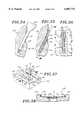
- FIG. 13is a perspective view of an intraocular lens, made by the techniques described herein;
- FIG. 14is a perspective view of a reverse mold pattern, ten times the size of the final reverse mold, having an aspherical portion;
- FIG. 15is an exploded perspective view of the pattern illustrated in FIG. 14, showing the various sections of the pattern;
- FIG. 16is a perspective view of a pantograph, used to replicate the pattern onto the surface of a coining mandrel, one-tenth of the original size;
- FIG. 17is a perspective view of a reverse mold, or coining mandrel, having an optical surface polished thereon;
- FIG. 18is an exploded perspective view of a mold forming assembly, used in the fabrication technique of the present invention.
- FIG. 19is a cross-sectional view of the forming assembly of FIG. 18, just prior to pressing the mold cavity;
- FIG. 20is a perspective view of a mold half formed in the assembly of FIG. 19;
- FIG. 21is an enlarged cross-sectional view, taken along line 21--21 of FIG. 20, showing the slight eruption of metal displaced during the mold forming process;
- FIG. 22is an enlarged partial cross-sectional view of the mold half of FIG. 23, showing the ground-off eruption in phantom lines and an overflow groove which has been machined around the optical cavity;
- FIG. 23is a perspective view of a top half of a mold made in accordance with the technique of the present invention.
- FIG. 24is a perspective view of a core pin and post assembly
- FIG. 25is a perspective view of a bottom half of a mold, showing the insertion of the core pin and post assembly of FIG. 24 in dashed lines;
- FIG. 26is a perspective view of the mold halves situated one over the other prior to the formation of a lens
- FIG. 27is a perspective view of a newly molded lens, showing the flashing, sporadically disposed about the periphery of the lens;
- FIG. 28is a cross-sectional view, taken along line 28--28 of FIG. 27;
- FIG. 29is a perspective view of an edge of the lens adjacent the aperture formed by the core pin subsequent to the tumbling of the lens;
- FIG. 30is a partially exploded perspective view of a forming mandrel used for making a control haptic
- FIG. 31is a top plan view of the forming mandrel illustrated in FIG. 30;
- FIG. 32is top plan view of the forming mandrel illustrated in FIGS. 30 and 31, showing the control haptic being formed;
- FIG. 33is a plan view of a control haptic
- FIG. 34is a partial cross-sectional view of an edge of a lens, illustrating the aperture being filled with adhesive
- FIG. 35is a partial cross-sectional view of an edge of a lens, showing the bonding of a haptic into the hole;
- FIG. 36is a cross-sectional view, taken along line 36--36 of FIG. 35, showing the angulation of the haptic within the hole;
- FIG. 37is a perspective view of a dihedral holding fixture used to maintain the haptics at a predetermined angle within the lens while the adhesive cures;
- FIG. 38is a cross-sectional view, taken along line 38--38 of FIG. 37, showing the disposition of a lens within the dihedral holding fixture;
- FIG. 39is a graph plotting the radius of curvature of the aspherical portion of the lens.
- FIG. 40is a partial cross-sectional view of an alternative coining assembly.
- FIG. 41is a profile of an intraocular lens, schematically illustrating the dioptric power increase of light passing through various portions of the lens, having various radii of curvature.
- FIG. 1there is represented a front perspective view from the distal side (or external side) of the intraocular lens of the present invention.
- the IOL of the present inventionis particularly designed for the surgical correction of aphakia following extracapsular cataract extraction.
- This lenticulasis to be implanted in the posterior chamber of the patient's eye and is designed to be placed in the ciliary sulcus.
- the IOL of the present inventionhas the general shape of a biconvex disk.
- the distal side 1, represented in FIG. 1has a generally spherical form with the exception of a sector 3 extending approximately from the mid-section of the distal side 1 to the lower quarter 4.
- the aspherical sector 3is configured such that the radius of curvature decreases monotonously from the value R 1 of the radius of the upper spherical sector 2, to a lower value R 0
- the lower spherical sector 4has the same radius as the upper spherical sector 3, namely R 0 . Because R 0 and R 1 are different, the aspherical sector 3 and the lower spherical sector 4 form an obtuse angle.
- R 0varies typically between 7 mm and 9 mm, whereas R 1 varies between 8 mm and 10 mm radius of curvature in the preferred embodiments of the present invention.
- the discontinuity 5 between the aspherical sector 3 and the lower spherical quarter 4is blocked out by dark or etched plastic in order to eliminate glare. However, the transition may be so slight as to preclude the need for any blocking or etching.
- the IOLis preferably made of polymethylmethacrylate (PMMA) or any other suitable material for IOL's such as silicon or hydrogel.
- the asphericity of the sector 3not only occurs along the axis X of the intraocular lens, hereinafter referred as the vertical axis, but also along the axis Z of the lens, hereinafter referred as the horizontal axis. More particularly, the planes XY, XZ and YZ are respectively called hereinafter the vertical plane, the distal plane and the horizontal plane of the lens.
- the discontinuity 5therefore extends from the lower quarter 4 to the mid-section of the lens on the edges and has an annular shape, as shown in FIG. 1.
- FIG. 2there is illustrated the first embodiment of the present invention in a side view.
- the proximal side 6is a convex surface in this embodiment.
- the distal side 1shows the three sectors hereabove described, namely the upper spherical sector 2, the central aspherical sector 3 and the lower spherical quarter 4.
- FIGS. 3 and 4there are illustrated two other embodiments of the present invention.
- the proximal side 7is a plane
- the proximal side 8is a concave surface.
- the distal sidehas the same configuration.
- FIG. 5is an explanatory optical diagram illustrating the multifocal property of the first preferred embodiment of the present invention as described hereabove. It should be noted, however, that the optical diagram of FIG. 5 holds true for the other embodiments of the present invention.
- a ray of light A impinging upon the lens on its spherical sector 2is focused in the far focal plane, as indicated by FF.
- the aspherical sectoris tangentially adjacent to the spherical sector 2 about the center of the mid-section of the IOL.
- the radius of curvature of the aspherical sector 3varies from R 0 , value of the radius of the spherical sector 2, to R 1 .
- a ray of light C impinging upon the bottom of the aspherical sectoris thus focused in a plane FN2 located between the lens and the far focal plane by virtue of elementary optical laws.
- the optic of the IOL of the present inventionprovides therefore both near vision through the aspherical sector 3 and distance vision through the spherical sectors 2 and 4.
- Light B from intermediate objectsis also adequately focused in FN1 by the aspherical sector 3 because of its varying radius of curvature.
- the degree of sphericitycan be chosen to permit a full dioptric range, thereby providing optimal post-operative vision.
- the principle underlying the functioning of the multifocal IOL herein disclosedreposes on the general concept that the brain selects one or the other of the images focused on the retina by the IOL. This selection is based on differences in contrast between the images perceived by the brain. Through each of the sectors of the IOL, the focused image and the unfocussed images are projected onto the retina, and the brain immediately selects the focused image. A loss of contrast
- FIG. 6there is represented a side view of a fourth embodiment of the present invention wherein the aspherical sector 3 extends approximately from the lower quarter 4 to the upper quarter .
- This aspherical sector 3therefore defines two discontinuities 5a and 5b which can be both blocked out to eliminate glare as stated hereinbefore.
- the aspherical sector 3extends over the entirety of the central part of the intraocular lens as in FIG. 6 with the exception of an angular sector 9 in the upper part of the lens. More generally, the aspherical sector 9 can take various shapes.
- the number of degrees of the aspherical sector in the plane of the lenticulascan vary from 180 degrees to 360 degrees as in FIG. 6 and can take any intermediary value, as illustrated in FIG. 7. A value inferior to 180 degrees is not excluded but may impair the near vision properties of the intraocular lens.
- FIG. 9there is illustrated a sixth embodiment of the present invention similar to the first embodiment, but wherein the asphericity of the sector 3 is achieved in discrete steps.
- the aspherical sectorextends from the lower quarter 4 to the mid-section 2 as in FIG. 2.
- the aspherical sectoris constituted of three spherical domains 3a, 3b and 3c, of decreasing value from R 0 to R 1 .
- the spherical sectors 3a, 3b and 3chave respectively the following refractive powers: 1 diopter, 2 diopters and 3 diopters.
- the spherical sectors 3a, 3b and 3ctake the form of concentric crescents around the center of the intraocular lens in the distal plane thereof.
- FIGS. 10 through 11illustrate a seventh embodiment of the invention using concentric spheric and aspheric zones. More specifically, the intermediary sector 13 is aspherical, while the central sector 12 and peripheral sector 14 are spherical. As in the previously described embodiments, the radius of curvature of the aspherical sector 13 decreases progressively as we get close to the peripheral sector 14. This embodiment of the invention is symmetrical about all meridians. As the diagram of FIG. 12 indicates, the most distant focal point 15 corresponds to the spherical median and peripheral sectors 12 and 14, while the various proximal focal points 16, 17 correspond to the continuously variable aspherical sector 13.
- the aspheric sectorcan begin anywhere on the surface of the intraocular lens and can be of any radius.
- the aspherical sectorhas the same radius as the lens itself and therefore extends from one edge of the lens to the other edge.
- a configuration wherein the aspherical sector occupies only the central part of the lens,is possible and would serve the same purpose as the embodiment more fully described hereabove.
- the proximal sidecan be otherwise configured.
- the intraocular lens 11is a biconvex lens having a first, or anterior side 21 and a second, or posterior side (not shown).
- the posterior sidewill reside in the capsule of the eye adjacent the vitreous humor, and is substantially spherical.
- the anterior side 21, however, as schematically illustrated,is asymmetric, and is formed of three sections 23, 25, 27.
- the upper, or superior section 23occupies the upper half of the lens and is substantially spherical, having essentially the same radius curvature as that of the posterior side of the lens.
- the center section 25 adjacent the superior section 23,extends from the center of the lens to the lower quarter, and exhibits an aspherical surface, having a gradually decreasing radius of curvature.
- the third section 27 of the lens 10vis also spherical, but exhibits a longer radius of curvature than that of the superior section 23 so as to provide a flatter surface and thus greater strength and thickness near the edge 20 of the lens, at the juncture of the two spherical sections 23, 27.
- a pair of support members, or haptics 22, 24are secured to the lens 10 on diametrically opposed sides, and aid in centering the lens 10 within the eye after implantation.
- the superior, or control haptic 22is provided with a horseshoe-like kink 26 which enables the ophthalmic surgeon to readily determine which is the superior portion 14 of the lens 10 and permits manipulation of the lens 10 during surgery.
- the pattern 28comprises three major components: a large semi-circular block 30, a small semi-circular block 32, and an arcuate block 34, having an outer diameter corresponding to the diameter of the large semi-circular block 30, and an inner diameter corresponding to the diameter of the small semi-circular block 32.
- the blocks 30, 32, 34are secured together by a plurality of bolts 36.
- the larger semi-circular block 30has a spherical surface 38, and corresponds to that portion which will ultimately be the superior half 23 of the anterior side 21 of the lens 10.
- the arcuate block 34corresponds to the outer, inferior section 27 of the lens 10, and is also provided with a spherical surface 40, although somewhat flatter than that of the large semi-circular block.
- the radius of curvature of the various portionsmust be shorter than that of the desired surface of the mold cavity to allow for "spring back" of the coined surface.
- the center of the mold cavitywhich is deeper than the periphery, "springs back" more than the periphery, since it has yielded more than the periphery.
- Empirical datahas shown that for a stainless steel mold cavity, the coined mold will have a radius of curvature which is 1 to 2% larger than the radius of curvature of the coining mandrel. A correction factor for this difference is made in the pattern by reducing its radii of curvature by 1 to 2%.
- silicone lenses made in such a moldtend to shrink a uniform 3.7% during the lens forming process. Therefore, the pattern, in addition to having shorter radii of curvature, should be enlarged by a factor of 3.7% to allow for such shrinkage.
- the radius of curvature of an optical elementis proportional to the focal length of that element. As the radius of curvature of an optical element decreases, the dioptric power, which is defined as the inverse of the focal length when measured in meters, increases.
- the small semi-circular block 32is configured such that the radius of curvature, on the surface 42 thereof, steadily decreases from a first value, R 0 , equal to the radius of curvature of the large semi-circular block 30, to a lower value, R N , determined by the desired change in the base power of the varifocal, or aspherical portion 25 of the lens 10.
- the entire posterior side 200 and the superior half 23 of the anterior side 21 of the lensare of fixed curvatures which determine the base power of the lens after implantation in the eye.
- the inferior half of the anterior side 21,is capable of providing varying levels of accommodation by virtue of the aspherical portion 25 of the lens.
- the dioptric power of an intraocular lensis typically controlled by varying the anterior and/or posterior radii of the optical element. If, for example, as illustrated in FIG.
- the posterior side 200is of a fixed radius of curvature, corresponding to a dioptric power of 9 diopters, and the superior half 23 of the anterior side 21 exhibits the same radius, and thus the same power of 9 diopters, then light impinging on the lens in this area, as designated by line 202, would be focused with a dioptric power of 18 (9+9) diopters.
- the center section 25 of the anterior side 21under goes a change in its radius of curvature, the focal point of light impinging therethrough would also change.
- FIG. 39schematically illustrates the changing radius of curvature (R 0 . . . R N ) throughout the varifocal portion of the lens.
- the radius of curvature (R 0 )begins at the same radius as that of the spherical portion, and then gradually decreases.
- Vthe width of the varifocal portion of the lens
- N 2the index of refraction of the lens
- N 1the index of refraction of aqueous in situ.
- the aspherical portion of the lensis a solid of rotation, formed by rotating the curve generated by the above equations, about a line which passes through the initial radius R 0 , to form the surface.
- Xthe distance from P 0 to P x .
- a pantograph 44which is an apparatus for transferring three-dimensional tracer pin motions to a cutting tool is illustrated in FIG. 16.
- the cutting tool 46moves in the same direction as the tracer pin 48, at a preset, duplicating ratio.
- the pantograph 44is employed to replicate the contours of the pattern 28 onto a workpiece 50 which is, in the preferred embodiment, ten times smaller than that of the pattern itself.
- the pattern 28 and the workpiece 50are clamped in conjugate positions at roughly the same level to ensure alignment of the cutter 46 and the tracer pin 48.
- the cutter 46is a high grade tungsten carbide tool, and spins at approximately 20,000 rpm.
- the cutter 46will replicate all of the pattern contours onto the workpiece 50 at the designated ratio.
- the pattern surfaceis replicated by carefully drawing the tracer pin 48 across the surface of the pattern 50 in small, circular strokes in steps of approximately 0.010". It is noteworthy that reproduction of the pattern 50 at one-tenth the desired size is advantageous in that any slight errors on the surface of the pattern will be proportionally reduced to the scale reduction out on the replica 54, to acceptable tolerances.
- the tracer pin 48may be driven manually or by a CNC machine (not shown).
- the replica 54is to be used as a coining mandrel for coining optical surfaces. It is to be understood that the term coining is used to define the permanent deformation of a soft material, as impressed by a harder material.
- the replica, or coining mandrel 54is a small, cylindrical piece of high-grade, hardenable alloy tool steel, capable of reaching a hardness of 58 Rockwell, Scale C (R c ). Most preferably, D-2 steel is used.
- the coining mandrel 54is then heat treated in an oven to harden the D-2 steel throughout to a hardness of between 58 to 62 Rockwell, Scale C (R c ), and most preferably, 60 R c which corresponds to a tensile strength of 320,000 p.s.i. Because oxygen tends to leave an undesirable coating on the surface of the steel during the heat treating process which would have to be sand-blasted off, the coining mandrel 54 is preferably hardened in one of two ways. The preferred way is to evacuate the air out of the oven to produce a vacuum environment and heat the coining mandrel by radiation to approximately 1300°. The coining mandrel is then allowed to slowly cool and will emerge from the oven within the desired range of hardness.
- the reverse mold surface 56must be polished to an optical surface.
- the general practiceis to polish the surface 56 of the mandrel 54 with a succession of polishing agents, progressing from a coarse grit to a finer grit. Because of the nature and intended use of the coining mandrel, as well as the minute surface area of the reverse mold surface, the coining mandrel must be hand polished under a microscope, allowing a better polish.
- Polishing the surface 56 of the coining mandrel 54is a very tedious process, and requires hours of meticulous work.
- the first step in the optical polishing of the coining mandrelis to remove all of the crowns and crests from the surface which were magnified during the hardening process. This is accomplished by applying a small amount of fine machine oil and 600 grit silicone carbide material to the surface of the coining mandrel and polishing it with small, circular motions using the end of a brass rod followed by the use of 1000 grit silicone carbide. To ensure that the surface of the coining mandrel is not being over polished and that the precisely calculated radii of curvature are maintained, a comparator is used during each step.
- the tumbleris filled with 1 and 2 mm glass beads, fine machine oil of the type used during the above polishing steps, an anti-settling agent and mineral spirits.
- the anti-settling agentis fumed silicone dioxide, having a particle size of between 0.7 to 2.7 angstroms ( ⁇ ), as made commercially available under the name Cab-O-Sil fumed silica.
- the fumed silicais used as a suspending or anti-settling agent in the tumbler and accelerates the polishing process during tumbling.
- tumbling mediasuch as water or alcohol are not suitable for use in the tumbler when polishing the coining mandrel 54 as these agents would cause electrolysis, which, in turn, would etch the surface 56 of the coining mandrel.
- the coining mandrelUpon cessation of the tumbling process, the coining mandrel should emerge having a highly polished optical surface of the desired configuration.
- FIG. 17illustrates a hardened, polished coining mandrel 54 which is to be used to stamp it's impression into a blank of a softer material, preferably having an optical finish on the face thereof, so as to form an optical power surface within a concave mold cavity.
- An optical power surfaceis one which is contoured to focus light rays so that they converge or diverge to form an image.
- the coining mandrelhas been hardened to 60 R c , the choice of softer materials would appear endless.
- the coining mandrel 54could be pressed into a polished piece of sheet metal 57, having a resilient backing 59, such as die rubber, placed thereunder.
- the coining mandrel 54When coining a mold cavity into such a soft material, the coining mandrel 54 need not be hardened to 60 R c , but can be as soft as 40 R c . As the mandrel 54 is pressed into the sheet metal 57, the sheet metal permanently deforms to assume a reverse configuration of the surface 56 of the coining mandrel 54. The rubber backing 59 will yield to the deformation of the sheet metal 57 during the coining process, however will spring back after the coining is completed and the assembly disassembled. It is noteworthy that a minimal amount of pressure is required to create a mold cavity in the sheet metal 57 due to the resilient nature of the rubber backing 59, and the thinness of the sheet metal 57 itself.
- the blank 58(shown in FIGS. 18 and 19) is formed of either a 300 type series or a 400 type series stainless steel.
- the 300 seriesis preferred, with 203 or 303 stainless steel proving well suited.
- the blank 58is machined in the desired shape and thickness, and the face 60 is optically lapped in a manner as is well known in the art.
- the face 60 of the blankis polished in a series of steps, beginning with 320 grit sandpaper and oil, and proceeding to finer grades of sandpaper, having grit sizes of 400 and 600.
- the blankis then polished using a lapping plate, having a urethane cover using 1 m Al 2 O 3 and water.
- the face 60 of the blank 58is optically finished with a rotary polisher, having a urethane felt cover, in a 0.3 m Al 2 O 3 and water slurry.
- a mold cavityis ready to be formed.
- a pair of drill bushings 62, 64are utilized to maintain the relative positioning of the coining mandrel 54 with respect to the diametric center of the polished blank 58.
- the bushingsare formed of tool steel, as they will ultimately be subjected to exceptionally high loads.
- the outer bushing 62is cored and has an inner diameter 66 sized to receive and center the polished blank 58 with minimal clearance about the periphery thereof, so as to ensure that the blank will not move during the mold formation process.
- the inner bushing 64is also cored, having an outer diameter 68 selected such that the inner bushing 64 will be centered with respect to the outer bushing 62 and an inner diameter 70, for centering the coining mandrel 54 will be centered with respect to the blank 58.
- the inner bushing 64is further equipped with a flange 72, adapted to rest on the upper rim 74 of the outer bushing 62 to maintain a small gap 76 between the bottom surface 78 of the inner bushing 64 and the blank 58.
- the outer bushing 62is placed on a hardened surface 80.
- the blank 58is inserted into the core 66 of the outer drill bushing 62, with the polished side up. It is important to execute care in the insertion of the blank 58 into the bushing 62, as scratches on the surface 60 of the blank 58 may result in a mold cavity which yields flawed lenses.
- the inner bushing 64is then inserted into the core 66 of the outer bushing 62, so that the flange 72 rests on the upper rim 74 of the outer drill bushing 62 and finally, the coining mandrel 54 is lowered into the core 70 of the inner bushing 64 until it just touches the surface 60 of the blank 58.
- a second hardened surface 82is carefully set on top of the coining mandrel 54, and the formation assembly 84 is put into a hydraulic press (not shown).
- the coining mandrel 54should extend outwardly above the flange 72 of the inner bushing 64, by an amount equal to the desired final depth of the mold cavity, taking into account the amount of compression, or shrinkage of the coining mandrel expected during the pressing of the mold cavity.
- the coining mandrel 54extends 0.043 inches above the flanged surface 72, allowing 0.012 inches for compression of the coining mandrel under full load, and will yield an imprint having a final depth of 0.031 inches. Because the 0.043 inch gap 88 is directly related to the desired depth of the resultant mold cavity, the hydraulic press may be slowly and steadily loaded until the gap 88 disappears.
- the hydraulic pressIn general, it takes a load of between 7 and 10 tons to stamp the coining mandrel impression into the steel blank at the desired depth.
- the hydraulic pressis loaded to 10 tons to ensure proper deformation of the mold cavity.
- a load of this magnitudeimposes a pressure in excess of 400,000 p.s.i. upon the surface 56 of the coining mandrel 54.
- the pressIn order to allow for the creeping of the materials, the press remains under full load for approximately 15 minutes after the gap 88 disappears.
- the coining mandrel 54compresses 0.012 inches. In addition, a radial expansion of approximately 0.001 inches in diameter is also experienced. However, the coining mandrel is not deformed beyond the elastic limit of the material, and therefore returns to its original form upon removal of the load. Unlike the coining mandrel 54, the stainless steel blank 58 has a much lower yield strength and therefore undergoes permanent deformation upon application of the load. Thus, not only does the newly formed mold half 90 exhibit a mold cavity 92, having a reverse imprint of the surface 56 of the coining mandrel 54 at the desired depth, as shown in FIG.
- the porosity in the mold cavity 92is substantially decreased, resulting in a smoother, higher quality optical surface than was present on the original optically polished blank, and the deformation of the blank material work hardens, resulting in a harder, more durable surface.
- the mold 96 used to form the biconvex intraocular lens 10 of the present inventioncomprises an upper mold half 98 with an upper concave cavity 100 and a lower mold half 90 with a lower concave cavity 92.
- a second, or upper mold half 98must be made.
- the mold cavity 100 of the upper mold half 98will have a spherical surface which will provide the desired additional base power of the lens.
- the upper mold half 98is made in the same manner as the lower mold half 90 with the exception of the surface configuration of the mold cavity.
- the upper mold cavity 100is preferably spherical, having a radius of curvature selected in accordance with the desired refractive power of the resultant lens. Having formed the concave cavities 92, 100 in each of the mold halves 90, 98, the eruptions 94 (FIG. 21) surrounding the periphery of each cavity must be ground off.
- each mold cavity 92, 100was pressed in to a depth of 0.031 inches to allow for imperfections in the blank 58, as well as these eruptions 94.
- an adhesive backed disc 193, or other type of coveringhaving a light adhesive backing to prevent slippage and having a known thickness, is carefully placed on the surface of each mold cavity during the grinding and machining processes. As shown in FIG. 22, the face 102 of each mold half 90, 98 is ground down until a final mold cavity depth of 0.025 inches is attained.
- an overflow groove 104is machined using a lathe, around the periphery of each mold cavity 92, 100.
- a thin ridge 106referred to as the mold shut off, or flash line, is created intermediate the groove 104 and the respective mold cavity 92, 100 so that concentric circles are formed about the mold cavity.
- the flash line 106defines the outer limits of the molded lens.
- a pair of alignment dowel pins 108, 110are secured to the bottom half of the mold 90 in a conventional manner.
- Associated mating holes 112, 114are drilled into the top half of the mold 98 (FIG.
- Each mold half 90, 98is machined to provide a pair of elongate grooves 116, 118 on diametrically opposed sides of the mold.
- the elongate grooves 116, 118are semi-cylindrical in cross-section and are adapted to receive and maintain the positioning of a pair of core pins 120, about which the silicone lens material will cure during its production.
- a pair of small dowel pins 122, 124is provided in the overflow groove 104, on opposite sides of each core pin 120, to sandwich the core pin therebetween.
- each core pin 120is secured to a post 126, which is removable from the bottom mold half 90.
- the core pins 120may be lifted from the mold, together with the lens so that the core pins do not tear the lens during the removal of the lens from the mold.
- the lensis removed from the mold by pushing the posts 126 upwardly from the bottom half of the mold 90 through the hole 127 with a lifter pin (not shown). In this manner, the optical power surfaces of the mold are less likely to be damaged by removing tools being inserted under the lens.
- FIG. 26illustrates a complete mold assembly 96.
- the upper and lower halves of the mold 90, 98are relatively movable towards and away from each other to allow the introduction of material which will form the optical element therein.
- the lensesare produced via compression molding, although other molding processes, such as injection molding, may also be employed.
- Silicone, in a liquid form, having a volume somewhat greater than that of the two mold cavitiesis introduced into the lower mold cavity 99.
- Preferably, about 0.025 milliliters of uncured, liquid siliconeis used to form the lens.
- the upper half of the mold 98is then brought into engagement with the lower half 92 so that the alignment dowel pins 108, 110 are met by the associated mating holes 112, 114.
- the mold 96is closed, the excess volume of silicone will leak out between the mold parts and into the overflow grooves 104.
- the mold 96is then heated for a predetermined time at an elevated predetermined temperature that will polymerize the monomers located therein into a solid polymer. In the preferred embodiment, the mold is heated for 10 minutes at 300° F. Following the polymerization of the optical element material, the mold is opened, and the optical element is removed therefrom.
- the tumbleris filled with 1 to 6 mm glass beads, isopropyl alcohol, and fumed silicone dioxide.
- Al 2 O 3is used as the polishing agent when tumbling PMMA lenses to speed up the tumbling process and water is used as the tumbling medium.
- fumed silicone dioxideis used as the polishing agent to accelerate the tumbling process.
- fumed silicone dioxideWhen using fumed silicone dioxide as a polishing agent and water, the silicone lenses tend to float out and not polish.
- Isopropyl alcoholhowever, has a lower surface tension than water, and a lower specific gravity than silicone and will allow the lenses to sink, thereby making it an ideal tumbling matrix.
- the isopropyl alcoholhas another advantage in that the silicone lens material absorbs a portion of the alcohol, causing the lenses to uniformly swell an average of 7%, which in turn, lowers the tear strength of the lens material. As the tear strength decreases, the abrading process, caused by the tumbling action of the tumbler, is further accelerated.
- the tumbling processtends to abrade more rapidly at lip or margin 138 of the holes 130, 132 formed by the core pins during the production of the lens because this area of the lens is thinner. This is significant in that, as illustrated in FIG. 29, at the cessation of the tumbling process, the optical element 140 is left with an indentation 142 proximate the holes 130, 132. Further, the flash, created during the production of the lens in the area where the two mold halves met, substantially disappears after tumbling, leaving a smoothly radiused, ogive shaped lens having a blended, radiused edge. In addition, a thin layer of fumed silicone dioxide will be present on both the outer surface of the lens, as well as the surface within the holes 130, 132.
- FIGS. 30-32illustrate a forming mandrel 144 for making control haptics 22.
- Haptics 22, 24may be formed from any material, but are preferably formed from a solid polymer member, designed to be relatively thin and flexible, yet provide sufficient support for the optical element 140.
- Materials found well suited to the formation of hapticsinclude polypropylene; PMMA, polyamide, polyethylene, nylon, and great number of extruded plastics.
- the hapticsare formed of polypropylene, or any 5-0 medical non-abradable suture, having a substantially circular cross-section of approximately 0.006 inches in diameter, as commonly available from Ethicon, a division of Johnson and Johnson, as well as Davis and Geck, a division of American Cyanamide.
- the forming mandrel 144comprises a base 146 upon which a pair of forming blocks 148, 150 are mounted.
- Block 148is adapted to form the distal, or free end 152 of the haptic while block 150 is precisely formed to the desired contours of the proximal end 154 of the haptic.
- the blocks 148, 150are positioned on the base 146, adjacent one another, leaving a small void 156 therebetween.
- a control loop pin 158sized slightly larger than the void 156, is provided for the formation of the horseshoe-like kink 26, characteristic of the control haptic 22.
- the control loop pin 158is sized such that when the suture material is wrapped around it, as illustrated in FIGS. 30-32, the combination of the control loop pin 158 and the suture material is larger than the void 156. This is significant in that it will yield a control haptic 22, having a control loop 26 with a kinked portion which is greater than 180°, but less than 360°, to assist the ophthalmic surgeon in more readily determining which is the superior side of the lens.
- the kinked portion of the control loop 26is at least semi-circular, having an eyelet-like shape, but does not form a complete circle.
- the control loop pin 158is placed between the blocks 148, 150 and both ends of the suture are passed through the void 156.
- the suture 160is then pulled tightly against the blocks 148, 150, conforming to the contours of the forming mandrel 144, and secured thereto, preferably by tying a knot in the suture material, intermediate blocks 148, 150 and opposite the control loop pin 158.
- a retaining bar(not shown) is placed against the control loop pin 158 intermediate the blocks 148, 150 to bias the suture material 160 toward the pin during the remainder of the control haptic forming process.
- the wrapped forming mandrelis then placed in a Nitrogen oven and heated at a temperature of between 300° F. and 350° F. for approximately one hour.
- the suture materialis heat set at 320° F., during which time it will deform to assume the shape of the forming mandrel 144, and produce a control haptic 22.
- the mandrel and hapticsAfter the mandrel and haptics have been allowed to cool, they are cut off of the forming mandrel with a razor blade along grooves 162 and 164.
- Haptics without the control loopmay also be formed by the same procedure, without the use of the control loop pin.
- the hapticsare then tumbled in a standard intraocular lens tumbler, using the standard proportions of water, 0.3 m Al 2 O 3 and glass beads to round off the ends of the haptics.
- the resultant control haptic 22is illustrated in FIG. 33.
- the proximal end 154 of the hapticis somewhat bent at an angle, so that the haptic, when bonded to the optical element 140, will be tangential thereto.
- Prior to bonding the haptics 22, 24 within the apertures 130, 132 formed in the lensthey must be surgically cleaned. This is accomplished by thoroughly rinsing the haptics in isopropyl alcohol, heated to about 150° F.
- a high frequency corona surface treater(not shown) is used to surface charge the proximal end 154 of the haptic.
- Such surface treatmentis not permanent, and decays with time to some limiting value which is dependent upon the particular material being used. Further, corona treated surfaces are not mechanically durable, and should therefore be disturbed as little as possible.
- the proximal end of the haptic, which is to be surface treated by the corona dischargeis passed beneath an emitting electrode at a speed and distance from the electrode which is determined by the amount of treatment required.
- the treated end of the hapticis preferably coated with a primer immediately after being passed through the corona discharge.
- a primerPreferably, a specially formulated, one component unpigmented silicone primer, as available from McGhan NuSil Corporation, and sold under the name CF1-135 High Technology Silicone Primer, is used.
- This primeris an air-drying primer, designed to improve the adhesion of cured silicones to various substrates.
- a uniform thin coat of primershould be applied to the proximal end of the haptic following treatment of the surface. This may be accomplished by brushing, wiping, dipping or spraying the primer onto the haptic, although dipping is the preferred method.
- a silicone adhesive 166is drawn into a 1 cc tuberculin syringe 168, shown in FIG. 34.
- the adhesiveis RTV-118 silicone rubber adhesive sealant, as commonly available from the Silicone Products Division of General Electric.
- the adhesivecan be medical adhesive silicone type A, as manufactured by Dow Corning Corporation, under the name Silastic. These adhesives are easily applied, translucent, non-flowing soft silicone adhesives, ideally suited for bonding silicone elastomers to itself as well as other synthetics.
- a 30 gauge needle 170having a diameter of 0.012", and a blunt end 172 which has been cut off and polished round, as illustrated in FIG.
- the syringe 168Prior to the injection of the adhesive 166 into the apertures 130, 132, the needle 170 is fully inserted into the aperture. The adhesive 166 is then slowly injected and the syringe slowly withdrawn from the aperture until the aperture is approximately two-thirds full of adhesive. It is important that the syringe needle 170 be fully inserted into the aperture and backed out of the aperture while the adhesive is being injected, as air pressure in the aperture would tend to force the adhesive outward. The proximal end 154 of the haptic is then inserted into the adhesive-filled aperture as illustrated in FIG. 35, displacing a small quantity of the adhesive.
- hapticit is beneficial to have as long a haptic as possible without unduly increasing the size of the intraocular lens.
- Longer hapticshave the advantage over shorter haptics in that they are less rigid, substantially softer and more flexible and, most importantly, less traumatic to the eye after implantation.
- a haptic that completely encircles the optical element of the intraocular lens, however,would not be preferable, as it would increase the surface area of the lens, necessitating a larger incision into the eye for implanting. Fortunately, because of the indentation 142 at the lip 138 of the lens 140 formed during the tumbling process, and the angle at which the proximal end 154 of the haptic is subtended, the haptic emerges tangentially from the lens.
- the tangential alignment and bonding of the haptic with the lensenables the implementation of a haptic having the maximum possible length without necessitating an increase in width. This is significant in that it allows one to use a longer haptic, having the aforementioned advantages of suppleness and flexibility which are instrumental in providing a comfortable and non-irritating means for fixating and properly positioning the intraocular lens within the eye.
- the width of the intraocular lensis not affected by the increased length of the haptic, the advantage of smaller incisions, made possible by the advances in phacoemulsification technology and associated with soft, foldable intraocular lenses is preserved.
- the hapticis one half the diameter of the aperture, it may be disposed at any number of desirable angles with respect to the lens.
Landscapes
- Engineering & Computer Science (AREA)
- Health & Medical Sciences (AREA)
- Mechanical Engineering (AREA)
- Ophthalmology & Optometry (AREA)
- Manufacturing & Machinery (AREA)
- General Health & Medical Sciences (AREA)
- Transplantation (AREA)
- Oral & Maxillofacial Surgery (AREA)
- Cardiology (AREA)
- Biomedical Technology (AREA)
- Heart & Thoracic Surgery (AREA)
- Vascular Medicine (AREA)
- Life Sciences & Earth Sciences (AREA)
- Animal Behavior & Ethology (AREA)
- Microelectronics & Electronic Packaging (AREA)
- Public Health (AREA)
- Veterinary Medicine (AREA)
- Prostheses (AREA)
Abstract
Description
P.sub.x =P.sub.0 +(X*P)/V
S.sub.x ≈V(1-R.sub.x /R.sub.0).
Claims (4)
Priority Applications (1)
| Application Number | Priority Date | Filing Date | Title |
|---|---|---|---|
| US08/472,051US6007747A (en) | 1987-08-24 | 1995-06-06 | Method of making an aspheric soft lens |
Applications Claiming Priority (8)
| Application Number | Priority Date | Filing Date | Title |
|---|---|---|---|
| US07/088,227US4769033A (en) | 1987-07-02 | 1987-08-24 | Intraocular multifocal lens |
| US07/232,140US4917681A (en) | 1987-08-24 | 1988-08-15 | Intraocular multifocal lens |
| US07/262,985US5104590A (en) | 1988-10-26 | 1988-10-26 | Fabrication of an intraocular lens |
| US07/509,871US5019099A (en) | 1987-07-02 | 1990-04-16 | Intraocular multifocal lens method for correcting the aphakic eye |
| US62673690A | 1990-12-13 | 1990-12-13 | |
| US2852293A | 1993-03-10 | 1993-03-10 | |
| US08/161,194US6797003B1 (en) | 1987-08-24 | 1993-12-01 | Aspheric soft lens |
| US08/472,051US6007747A (en) | 1987-08-24 | 1995-06-06 | Method of making an aspheric soft lens |
Related Parent Applications (2)
| Application Number | Title | Priority Date | Filing Date |
|---|---|---|---|
| US07/509,871Continuation-In-PartUS5019099A (en) | 1987-07-02 | 1990-04-16 | Intraocular multifocal lens method for correcting the aphakic eye |
| US08/161,194DivisionUS6797003B1 (en) | 1987-08-24 | 1993-12-01 | Aspheric soft lens |
Publications (1)
| Publication Number | Publication Date |
|---|---|
| US6007747Atrue US6007747A (en) | 1999-12-28 |
Family
ID=27567752
Family Applications (1)
| Application Number | Title | Priority Date | Filing Date |
|---|---|---|---|
| US08/472,051Expired - LifetimeUS6007747A (en) | 1987-08-24 | 1995-06-06 | Method of making an aspheric soft lens |
Country Status (1)
| Country | Link |
|---|---|
| US (1) | US6007747A (en) |
Cited By (28)
| Publication number | Priority date | Publication date | Assignee | Title |
|---|---|---|---|---|
| WO2001047437A1 (en)* | 1999-12-29 | 2001-07-05 | Medennium, Inc. | Methods of surface treatment for enhancing the performance of a floating phakic refractive lens design |
| WO2001089424A1 (en) | 2000-05-23 | 2001-11-29 | Pharmacia Groningen Bv | Methods of obtaining ophthalmic lenses providing the eye with reduced aberrations |
| US6609793B2 (en) | 2000-05-23 | 2003-08-26 | Pharmacia Groningen Bv | Methods of obtaining ophthalmic lenses providing the eye with reduced aberrations |
| US20040106992A1 (en)* | 2002-11-08 | 2004-06-03 | Lang Alan J. | Multi-zonal monofocal intraocular lens for correcting optical aberrations |
| US20050043794A1 (en)* | 2003-03-31 | 2005-02-24 | Edward Geraghty | Aspheric intraocular lens |
| US20060244905A1 (en)* | 2002-11-29 | 2006-11-02 | Advanced Medical Optics, Inc. | Multifocal ophthalmic lens |
| US20060244906A1 (en)* | 2002-11-29 | 2006-11-02 | Advanced Medical Optics, Inc. | Multifocal ophthalmic lens |
| US7177550B1 (en)* | 2001-01-24 | 2007-02-13 | Ball Aerospace & Technologies Corp. | On-axis laser receiver wavelength demultiplexer with integral immersion lensed detectors |
| US20070093891A1 (en)* | 2005-10-26 | 2007-04-26 | Juan Tabernero | Intraocular lens for correcting corneal coma |
| US7455404B2 (en) | 2004-10-25 | 2008-11-25 | Advanced Medical Optics, Inc. | Ophthalmic lens with multiple phase plates |
| US20100234943A1 (en)* | 2009-03-11 | 2010-09-16 | Valdemar Portney | Non-prolate aspheric intraocular lens |
| US7922326B2 (en) | 2005-10-25 | 2011-04-12 | Abbott Medical Optics Inc. | Ophthalmic lens with multiple phase plates |
| US8020995B2 (en) | 2001-05-23 | 2011-09-20 | Amo Groningen Bv | Methods of obtaining ophthalmic lenses providing the eye with reduced aberrations |
| CN102189648A (en)* | 2011-04-08 | 2011-09-21 | 上海嘉视光学科技有限公司 | Flat topped bifocals model core of polycarbonate (PC) lens used for eyes |
| US9335563B2 (en) | 2012-08-31 | 2016-05-10 | Amo Groningen B.V. | Multi-ring lens, systems and methods for extended depth of focus |
| WO2018037356A1 (en) | 2016-08-23 | 2018-03-01 | Medicem Ophthalmic (Cy) Limited | Ophthalmic lenses with aspheric optical surfaces and method for their manufacture |
| US10624735B2 (en) | 2016-02-09 | 2020-04-21 | Amo Groningen B.V. | Progressive power intraocular lens, and methods of use and manufacture |
| US11156853B2 (en) | 2017-06-28 | 2021-10-26 | Amo Groningen B.V. | Extended range and related intraocular lenses for presbyopia treatment |
| US11262598B2 (en) | 2017-06-28 | 2022-03-01 | Amo Groningen, B.V. | Diffractive lenses and related intraocular lenses for presbyopia treatment |
| US11327210B2 (en) | 2017-06-30 | 2022-05-10 | Amo Groningen B.V. | Non-repeating echelettes and related intraocular lenses for presbyopia treatment |
| US11452595B2 (en) | 2007-08-27 | 2022-09-27 | Amo Groningen B.V. | Multizonal lens with enhanced performance |
| US11497599B2 (en) | 2017-03-17 | 2022-11-15 | Amo Groningen B.V. | Diffractive intraocular lenses for extended range of vision |
| US11506914B2 (en) | 2010-12-01 | 2022-11-22 | Amo Groningen B.V. | Multifocal lens having an optical add power progression, and a system and method of providing same |
| US11523897B2 (en) | 2017-06-23 | 2022-12-13 | Amo Groningen B.V. | Intraocular lenses for presbyopia treatment |
| US11844689B2 (en) | 2019-12-30 | 2023-12-19 | Amo Groningen B.V. | Achromatic lenses and lenses having diffractive profiles with irregular width for vision treatment |
| US11886046B2 (en) | 2019-12-30 | 2024-01-30 | Amo Groningen B.V. | Multi-region refractive lenses for vision treatment |
| CN117549173A (en)* | 2023-12-26 | 2024-02-13 | 张家港市光学仪器有限公司 | Aspherical convex lens processing method |
| US12204178B2 (en) | 2018-12-06 | 2025-01-21 | Amo Groningen B.V. | Diffractive lenses for presbyopia treatment |
Citations (86)
| Publication number | Priority date | Publication date | Assignee | Title |
|---|---|---|---|---|
| US385905A (en)* | 1888-07-10 | Cushioned die for swaging sheet-metal articles | ||
| FR1103399A (en)* | 1953-12-22 | 1955-11-02 | Microttica | Lenses intended for application in the anterior chamber of the eye |
| US2823417A (en)* | 1954-05-20 | 1958-02-18 | Ermanno Zanini | Means for producing optical lenses from plastic materials |
| US3034403A (en)* | 1959-04-03 | 1962-05-15 | Neefe Hamilton Res Company | Contact lens of apparent variable light absorption |
| US3270099A (en)* | 1964-12-07 | 1966-08-30 | Richard N Camp | A method for making multi-focal length contact lenses |
| US3339997A (en)* | 1962-07-30 | 1967-09-05 | Plastic Contact Lens Company | Bifocal ophthalmic lens having different color distance and near vision zones |
| US3440306A (en)* | 1966-07-11 | 1969-04-22 | Charles W Neefe | Process for making an improved bifocal lens |
| US3507552A (en)* | 1965-12-01 | 1970-04-21 | Us Navy | Flashblindness protective apparatus |
| US3510206A (en)* | 1966-03-07 | 1970-05-05 | Richard D Smith | Transparent mirror having electromagnetically adjustable reflector elements |
| US3560598A (en)* | 1968-10-11 | 1971-02-02 | Charles W Neefe | Process for making plastic multifocal lenses |
| US3693301A (en)* | 1970-05-27 | 1972-09-26 | Anvar | Method for producing optical elements with aspherical surfaces |
| US3712718A (en)* | 1970-10-23 | 1973-01-23 | J Legrand | Corneal contact lens |
| US3711870A (en)* | 1971-12-07 | 1973-01-23 | R Deitrick | Artificial lens implant |
| US3760045A (en)* | 1967-12-12 | 1973-09-18 | H Thiele | Process of preparing shaped optical bodies useful as aids to vision |
| US3866249A (en)* | 1974-03-07 | 1975-02-18 | Leonard Flom | Posterior chamber artificial intraocular lens |
| US3894710A (en)* | 1973-08-29 | 1975-07-15 | George M J Sarofeen | Mold forms coating synthetic resin lenses |
| US3950082A (en)* | 1973-01-10 | 1976-04-13 | David Volk | Ophthalmic lens for presbyopia and aphakia |
| US3962505A (en)* | 1974-10-18 | 1976-06-08 | Avery Theodore P | Plastic contact lens with magnetic embedded metal ring |
| US3991426A (en)* | 1975-02-14 | 1976-11-16 | Leonard Flom | Posterior chamber artificial intraocular lens with retaining means and instruments for use therewith |
| US4010496A (en)* | 1975-10-01 | 1977-03-08 | Neefe Charles W | Bifocal lens which positions within the anterior chamber |
| US4025965A (en)* | 1976-03-16 | 1977-05-31 | American Optical Corporation | Intraocular lenses |
| DE2556665A1 (en)* | 1975-12-16 | 1977-06-30 | Titmus Eurocon Kontaktlinsen K | Intraocular, artificial, lens with optical and supporting parts - has haptic edge in front of iris and loops behind it |
| US4053953A (en)* | 1976-01-14 | 1977-10-18 | Leonard Flom | Posterior chamber artificial intraocular lens with retaining means and instruments for use therewith adapted to provide extraocular confirmation of operative engagement |
| US4080709A (en)* | 1976-05-28 | 1978-03-28 | Stanley Poler | Method of making an intra-ocular lens |
| US4092743A (en)* | 1976-10-04 | 1978-06-06 | Kelman Charles D | Intraocular lenses |
| US4104339A (en)* | 1975-12-03 | 1978-08-01 | Fetz James G | Method for the manufacture of intraocular lenses |
| US4110848A (en)* | 1977-05-06 | 1978-09-05 | Ronald P. Jensen | Intraocular lens for implantation into the posterior chamber of a human eye |
| US4121885A (en)* | 1974-04-29 | 1978-10-24 | Precision Cosmet Co., Inc. | Method to produce a composite contact lens |
| DE2717706A1 (en)* | 1977-04-21 | 1978-10-26 | Leonhard Klein | Eye implant lens after cataract operation - has three equally spaced synthetic rubber centering rings around periphery |
| DE2725219A1 (en)* | 1977-06-03 | 1978-12-14 | Titmus Eurocon Kontaktlinsen K | Intra=ocular lens for fitting inside a wearer's iris - is made of silicone rubber and has deformable holding and supporting ribs |
| US4150073A (en)* | 1977-05-25 | 1979-04-17 | Neefe Charles W | Method of controlling the adhesion of a molded plastic lens to the mold |
| US4169119A (en)* | 1976-04-15 | 1979-09-25 | Permavision | Method of molding an ocular membrane |
| US4172297A (en)* | 1976-02-24 | 1979-10-30 | Inprohold Establishment | Artificial implant lens |
| US4179484A (en)* | 1977-05-25 | 1979-12-18 | Neefe Charles W | Method of making toric lenses |
| US4198714A (en)* | 1977-05-06 | 1980-04-22 | Jensen Ronald P | Intraocular lens for implantation into the posterior chamber of a human eye |
| US4244060A (en)* | 1978-12-01 | 1981-01-13 | Hoffer Kenneth J | Intraocular lens |
| US4251887A (en)* | 1979-04-02 | 1981-02-24 | Anis Aziz Y | Posterior chamber capsular lens implant and method for implantation of the lens |
| US4315337A (en)* | 1979-07-26 | 1982-02-16 | Choyce David P | Autoclavable anterior chamber implant |
| US4316293A (en)* | 1979-08-27 | 1982-02-23 | Bayers Jon Herbert | Flexible intraocular lens |
| US4365360A (en)* | 1979-04-05 | 1982-12-28 | Ong Tiong S | Lens designed for implantation into a lens capsule of a human eye |
| US4373218A (en)* | 1980-11-17 | 1983-02-15 | Schachar Ronald A | Variable power intraocular lens and method of implanting into the posterior chamber |
| US4377329A (en)* | 1980-02-26 | 1983-03-22 | Stanley Poler | Contact lens or the like |
| US4418991A (en)* | 1979-09-24 | 1983-12-06 | Breger Joseph L | Presbyopic contact lens |
| US4450593A (en)* | 1981-11-09 | 1984-05-29 | Lynell Medical Technology Inc. | Intraocular and contact lens construction |
| US4460523A (en)* | 1983-01-31 | 1984-07-17 | Neefe Charles W | Method of making cosmetic contact lenses |
| US4504982A (en)* | 1982-08-05 | 1985-03-19 | Optical Radiation Corporation | Aspheric intraocular lens |
| US4512040A (en)* | 1982-06-09 | 1985-04-23 | Mcclure Hubert L | Bifocal intraocular lens |
| US4527294A (en)* | 1983-12-16 | 1985-07-09 | Heslin K B | Intraocular lens construction |
| US4573998A (en)* | 1982-02-05 | 1986-03-04 | Staar Surgical Co. | Methods for implantation of deformable intraocular lenses |
| US4576453A (en)* | 1984-08-03 | 1986-03-18 | Richard Borowsky | Light-occluding contact lens |
| US4615702A (en)* | 1984-09-10 | 1986-10-07 | Koziol Jeffrey E | Intraocular lens and method of forming the lens |
| US4619662A (en)* | 1985-04-19 | 1986-10-28 | Juergens Jr Albert M | Intraocular lens |
| US4640595A (en)* | 1984-05-02 | 1987-02-03 | David Volk | Aspheric contact lens |
| US4655774A (en)* | 1986-01-03 | 1987-04-07 | Choyce D Peter | Intra-corneal implant for correction of aniridia |
| US4659524A (en)* | 1985-03-12 | 1987-04-21 | Neefe Charles W | Method of molding bifocal contact lenses |
| US4666446A (en)* | 1986-05-06 | 1987-05-19 | Koziol Jeffrey E | Intraocular lens with converging and diverging optical portions |
| US4673406A (en)* | 1984-10-29 | 1987-06-16 | Inprohold Establishment | One-piece implantation lens |
| US4701288A (en)* | 1985-06-05 | 1987-10-20 | Bausch & Lomb Incorporated | Method of making articles of dissimilar polymer compositions |
| US4702244A (en)* | 1982-02-05 | 1987-10-27 | Staar Surgical Company | Surgical device for implantation of a deformable intraocular lens |
| US4707236A (en)* | 1984-08-03 | 1987-11-17 | Richard Borowsky | Method of farbricating an optically graded light occluding gel |
| US4710193A (en)* | 1986-08-18 | 1987-12-01 | David Volk | Accommodating intraocular lens and lens series and method of lens selection |
| US4731078A (en)* | 1985-08-21 | 1988-03-15 | Kingston Technologies Limited Partnership | Intraocular lens |
| US4752123A (en)* | 1985-11-19 | 1988-06-21 | University Optical Products Co. | Concentric bifocal contact lens with two distance power regions |
| US4753520A (en)* | 1986-11-17 | 1988-06-28 | General Instrument Corp. | Compound catoptric cartesian ovoid lens |
| US4753653A (en)* | 1986-11-03 | 1988-06-28 | Precision-Cosmet Co., Inc. | Foldable bifocal intraocular lens |
| US4759762A (en)* | 1985-03-08 | 1988-07-26 | Grendahl Dennis T | Accommodating lens |
| US4769033A (en)* | 1987-07-02 | 1988-09-06 | Nordan Lee T | Intraocular multifocal lens |
| US4895585A (en)* | 1987-09-16 | 1990-01-23 | U.S. Philips Corp. | Method of manufacturing lens elements |
| US4898461A (en)* | 1987-06-01 | 1990-02-06 | Valdemar Portney | Multifocal ophthalmic lens |
| US4917681A (en)* | 1987-08-24 | 1990-04-17 | Nordan Lee T | Intraocular multifocal lens |
| JPH0371898A (en)* | 1989-08-10 | 1991-03-27 | Mitsubishi Pencil Co Ltd | Resin nib having ink outflow gap |
| US5019099A (en)* | 1987-07-02 | 1991-05-28 | Nordan Lee T | Intraocular multifocal lens method for correcting the aphakic eye |
| US5074877A (en)* | 1987-07-02 | 1991-12-24 | Nordan Lee T | Intraocular multifocal lens |
| US5192318A (en)* | 1986-06-05 | 1993-03-09 | Schneider Richard T | One-piece bifocal intraocular lens construction |
| US5236452A (en)* | 1987-07-02 | 1993-08-17 | Nordan Lee T | Intraocular multifocal lens |
| US5300117A (en)* | 1990-09-04 | 1994-04-05 | Laboratories Domilens | Intraocular implant for correction of myopia |
| US5326348A (en)* | 1987-07-02 | 1994-07-05 | Nordan Lee T | Intraocular multifocal lens |
| US5354335A (en)* | 1993-02-04 | 1994-10-11 | Isaac Lipshitz | Intraocular insert for implantation in the human eye |
| US5354334A (en)* | 1992-06-29 | 1994-10-11 | Komplex "Mikrokhirurgia Glaza" Mezhotraslevoi Nauchno-Tekhnichesky | Intraocular prosthetic lens and a method for surgical correction of diseases of the central section of the retina |
| US5366502A (en)* | 1989-04-28 | 1994-11-22 | Nestle S.A. | Supplementary intraocular lens system |
| US5366500A (en)* | 1986-06-05 | 1994-11-22 | Richard T. Schneider | One-piece bifocal intraocular lens construction |
| US5384606A (en)* | 1992-06-22 | 1995-01-24 | Allergan, Inc. | Diffractive/refractive spectacle and intraocular lens system for age-related macular degeneration |
| US5397511A (en)* | 1992-10-07 | 1995-03-14 | Menicon Co., Ltd. | Method of producing intraocular lens formed from polymide powder |
| US5405386A (en)* | 1993-07-09 | 1995-04-11 | Kabi Pharmacia Ophthalmics, Inc. | Intraocular lens with improved cylindrical haptic |
| US5405387A (en)* | 1992-10-13 | 1995-04-11 | Sodero; Maria A. | Intraocular lens |
| US5410375A (en)* | 1990-03-15 | 1995-04-25 | Fiala; Werner J. | Multifocal birefrigent lens with adjusted birefringence |
- 1995
- 1995-06-06USUS08/472,051patent/US6007747A/ennot_activeExpired - Lifetime
Patent Citations (89)
| Publication number | Priority date | Publication date | Assignee | Title |
|---|---|---|---|---|
| US385905A (en)* | 1888-07-10 | Cushioned die for swaging sheet-metal articles | ||
| FR1103399A (en)* | 1953-12-22 | 1955-11-02 | Microttica | Lenses intended for application in the anterior chamber of the eye |
| US2823417A (en)* | 1954-05-20 | 1958-02-18 | Ermanno Zanini | Means for producing optical lenses from plastic materials |
| US3034403A (en)* | 1959-04-03 | 1962-05-15 | Neefe Hamilton Res Company | Contact lens of apparent variable light absorption |
| US3339997A (en)* | 1962-07-30 | 1967-09-05 | Plastic Contact Lens Company | Bifocal ophthalmic lens having different color distance and near vision zones |
| US3270099A (en)* | 1964-12-07 | 1966-08-30 | Richard N Camp | A method for making multi-focal length contact lenses |
| US3507552A (en)* | 1965-12-01 | 1970-04-21 | Us Navy | Flashblindness protective apparatus |
| US3510206A (en)* | 1966-03-07 | 1970-05-05 | Richard D Smith | Transparent mirror having electromagnetically adjustable reflector elements |
| US3440306A (en)* | 1966-07-11 | 1969-04-22 | Charles W Neefe | Process for making an improved bifocal lens |
| US3760045A (en)* | 1967-12-12 | 1973-09-18 | H Thiele | Process of preparing shaped optical bodies useful as aids to vision |
| US3560598A (en)* | 1968-10-11 | 1971-02-02 | Charles W Neefe | Process for making plastic multifocal lenses |
| US3693301A (en)* | 1970-05-27 | 1972-09-26 | Anvar | Method for producing optical elements with aspherical surfaces |
| US3712718A (en)* | 1970-10-23 | 1973-01-23 | J Legrand | Corneal contact lens |
| US3711870A (en)* | 1971-12-07 | 1973-01-23 | R Deitrick | Artificial lens implant |
| US3950082A (en)* | 1973-01-10 | 1976-04-13 | David Volk | Ophthalmic lens for presbyopia and aphakia |
| US3894710A (en)* | 1973-08-29 | 1975-07-15 | George M J Sarofeen | Mold forms coating synthetic resin lenses |
| US3866249A (en)* | 1974-03-07 | 1975-02-18 | Leonard Flom | Posterior chamber artificial intraocular lens |
| US4121885A (en)* | 1974-04-29 | 1978-10-24 | Precision Cosmet Co., Inc. | Method to produce a composite contact lens |
| US3962505A (en)* | 1974-10-18 | 1976-06-08 | Avery Theodore P | Plastic contact lens with magnetic embedded metal ring |
| US3991426A (en)* | 1975-02-14 | 1976-11-16 | Leonard Flom | Posterior chamber artificial intraocular lens with retaining means and instruments for use therewith |
| US4010496A (en)* | 1975-10-01 | 1977-03-08 | Neefe Charles W | Bifocal lens which positions within the anterior chamber |
| US4104339A (en)* | 1975-12-03 | 1978-08-01 | Fetz James G | Method for the manufacture of intraocular lenses |
| DE2556665A1 (en)* | 1975-12-16 | 1977-06-30 | Titmus Eurocon Kontaktlinsen K | Intraocular, artificial, lens with optical and supporting parts - has haptic edge in front of iris and loops behind it |
| US4053953A (en)* | 1976-01-14 | 1977-10-18 | Leonard Flom | Posterior chamber artificial intraocular lens with retaining means and instruments for use therewith adapted to provide extraocular confirmation of operative engagement |
| US4172297A (en)* | 1976-02-24 | 1979-10-30 | Inprohold Establishment | Artificial implant lens |
| US4025965A (en)* | 1976-03-16 | 1977-05-31 | American Optical Corporation | Intraocular lenses |
| US4169119A (en)* | 1976-04-15 | 1979-09-25 | Permavision | Method of molding an ocular membrane |
| US4080709A (en)* | 1976-05-28 | 1978-03-28 | Stanley Poler | Method of making an intra-ocular lens |
| US4118808A (en)* | 1976-05-28 | 1978-10-10 | Stanley Poler | Intra-ocular lens |
| US4092743A (en)* | 1976-10-04 | 1978-06-06 | Kelman Charles D | Intraocular lenses |
| DE2717706A1 (en)* | 1977-04-21 | 1978-10-26 | Leonhard Klein | Eye implant lens after cataract operation - has three equally spaced synthetic rubber centering rings around periphery |
| US4110848A (en)* | 1977-05-06 | 1978-09-05 | Ronald P. Jensen | Intraocular lens for implantation into the posterior chamber of a human eye |
| US4198714A (en)* | 1977-05-06 | 1980-04-22 | Jensen Ronald P | Intraocular lens for implantation into the posterior chamber of a human eye |
| US4179484A (en)* | 1977-05-25 | 1979-12-18 | Neefe Charles W | Method of making toric lenses |
| US4150073A (en)* | 1977-05-25 | 1979-04-17 | Neefe Charles W | Method of controlling the adhesion of a molded plastic lens to the mold |
| DE2725219A1 (en)* | 1977-06-03 | 1978-12-14 | Titmus Eurocon Kontaktlinsen K | Intra=ocular lens for fitting inside a wearer's iris - is made of silicone rubber and has deformable holding and supporting ribs |
| US4244060A (en)* | 1978-12-01 | 1981-01-13 | Hoffer Kenneth J | Intraocular lens |
| US4251887A (en)* | 1979-04-02 | 1981-02-24 | Anis Aziz Y | Posterior chamber capsular lens implant and method for implantation of the lens |
| US4365360A (en)* | 1979-04-05 | 1982-12-28 | Ong Tiong S | Lens designed for implantation into a lens capsule of a human eye |
| US4315337A (en)* | 1979-07-26 | 1982-02-16 | Choyce David P | Autoclavable anterior chamber implant |
| US4316293A (en)* | 1979-08-27 | 1982-02-23 | Bayers Jon Herbert | Flexible intraocular lens |
| US4418991A (en)* | 1979-09-24 | 1983-12-06 | Breger Joseph L | Presbyopic contact lens |
| US4377329A (en)* | 1980-02-26 | 1983-03-22 | Stanley Poler | Contact lens or the like |
| US4373218A (en)* | 1980-11-17 | 1983-02-15 | Schachar Ronald A | Variable power intraocular lens and method of implanting into the posterior chamber |
| US4450593A (en)* | 1981-11-09 | 1984-05-29 | Lynell Medical Technology Inc. | Intraocular and contact lens construction |
| US4573998A (en)* | 1982-02-05 | 1986-03-04 | Staar Surgical Co. | Methods for implantation of deformable intraocular lenses |
| US4702244A (en)* | 1982-02-05 | 1987-10-27 | Staar Surgical Company | Surgical device for implantation of a deformable intraocular lens |
| US4512040A (en)* | 1982-06-09 | 1985-04-23 | Mcclure Hubert L | Bifocal intraocular lens |
| US4504982A (en)* | 1982-08-05 | 1985-03-19 | Optical Radiation Corporation | Aspheric intraocular lens |
| US4460523A (en)* | 1983-01-31 | 1984-07-17 | Neefe Charles W | Method of making cosmetic contact lenses |
| US4472327A (en)* | 1983-01-31 | 1984-09-18 | Neefe Charles W | Method of making hydrogel cosmetic contact lenses |
| US4527294A (en)* | 1983-12-16 | 1985-07-09 | Heslin K B | Intraocular lens construction |
| US4640595A (en)* | 1984-05-02 | 1987-02-03 | David Volk | Aspheric contact lens |
| US4707236A (en)* | 1984-08-03 | 1987-11-17 | Richard Borowsky | Method of farbricating an optically graded light occluding gel |
| US4576453A (en)* | 1984-08-03 | 1986-03-18 | Richard Borowsky | Light-occluding contact lens |
| US4615702A (en)* | 1984-09-10 | 1986-10-07 | Koziol Jeffrey E | Intraocular lens and method of forming the lens |
| US4673406A (en)* | 1984-10-29 | 1987-06-16 | Inprohold Establishment | One-piece implantation lens |
| US4759762A (en)* | 1985-03-08 | 1988-07-26 | Grendahl Dennis T | Accommodating lens |
| US4659524A (en)* | 1985-03-12 | 1987-04-21 | Neefe Charles W | Method of molding bifocal contact lenses |
| US4619662A (en)* | 1985-04-19 | 1986-10-28 | Juergens Jr Albert M | Intraocular lens |
| US4701288A (en)* | 1985-06-05 | 1987-10-20 | Bausch & Lomb Incorporated | Method of making articles of dissimilar polymer compositions |
| US4731078A (en)* | 1985-08-21 | 1988-03-15 | Kingston Technologies Limited Partnership | Intraocular lens |
| US4752123A (en)* | 1985-11-19 | 1988-06-21 | University Optical Products Co. | Concentric bifocal contact lens with two distance power regions |
| US4655774A (en)* | 1986-01-03 | 1987-04-07 | Choyce D Peter | Intra-corneal implant for correction of aniridia |
| US4666446A (en)* | 1986-05-06 | 1987-05-19 | Koziol Jeffrey E | Intraocular lens with converging and diverging optical portions |
| US5366500A (en)* | 1986-06-05 | 1994-11-22 | Richard T. Schneider | One-piece bifocal intraocular lens construction |
| US5192318A (en)* | 1986-06-05 | 1993-03-09 | Schneider Richard T | One-piece bifocal intraocular lens construction |
| US4710193A (en)* | 1986-08-18 | 1987-12-01 | David Volk | Accommodating intraocular lens and lens series and method of lens selection |
| US4753653A (en)* | 1986-11-03 | 1988-06-28 | Precision-Cosmet Co., Inc. | Foldable bifocal intraocular lens |
| US4753520A (en)* | 1986-11-17 | 1988-06-28 | General Instrument Corp. | Compound catoptric cartesian ovoid lens |
| US4898461A (en)* | 1987-06-01 | 1990-02-06 | Valdemar Portney | Multifocal ophthalmic lens |
| US5019099A (en)* | 1987-07-02 | 1991-05-28 | Nordan Lee T | Intraocular multifocal lens method for correcting the aphakic eye |
| US5074877A (en)* | 1987-07-02 | 1991-12-24 | Nordan Lee T | Intraocular multifocal lens |
| US5236452A (en)* | 1987-07-02 | 1993-08-17 | Nordan Lee T | Intraocular multifocal lens |
| US5326348A (en)* | 1987-07-02 | 1994-07-05 | Nordan Lee T | Intraocular multifocal lens |
| US4769033A (en)* | 1987-07-02 | 1988-09-06 | Nordan Lee T | Intraocular multifocal lens |
| US4917681A (en)* | 1987-08-24 | 1990-04-17 | Nordan Lee T | Intraocular multifocal lens |
| US4895585A (en)* | 1987-09-16 | 1990-01-23 | U.S. Philips Corp. | Method of manufacturing lens elements |
| US5366502A (en)* | 1989-04-28 | 1994-11-22 | Nestle S.A. | Supplementary intraocular lens system |
| JPH0371898A (en)* | 1989-08-10 | 1991-03-27 | Mitsubishi Pencil Co Ltd | Resin nib having ink outflow gap |
| US5410375A (en)* | 1990-03-15 | 1995-04-25 | Fiala; Werner J. | Multifocal birefrigent lens with adjusted birefringence |
| US5300117A (en)* | 1990-09-04 | 1994-04-05 | Laboratories Domilens | Intraocular implant for correction of myopia |
| US5384606A (en)* | 1992-06-22 | 1995-01-24 | Allergan, Inc. | Diffractive/refractive spectacle and intraocular lens system for age-related macular degeneration |
| US5354334A (en)* | 1992-06-29 | 1994-10-11 | Komplex "Mikrokhirurgia Glaza" Mezhotraslevoi Nauchno-Tekhnichesky | Intraocular prosthetic lens and a method for surgical correction of diseases of the central section of the retina |
| US5397511A (en)* | 1992-10-07 | 1995-03-14 | Menicon Co., Ltd. | Method of producing intraocular lens formed from polymide powder |
| US5405387A (en)* | 1992-10-13 | 1995-04-11 | Sodero; Maria A. | Intraocular lens |
| US5391202A (en)* | 1993-02-04 | 1995-02-21 | Lipshitz; Isaac | Intraocular insert for implantation in the human eye |
| US5354335A (en)* | 1993-02-04 | 1994-10-11 | Isaac Lipshitz | Intraocular insert for implantation in the human eye |
| US5405386A (en)* | 1993-07-09 | 1995-04-11 | Kabi Pharmacia Ophthalmics, Inc. | Intraocular lens with improved cylindrical haptic |
Non-Patent Citations (17)
| Title |
|---|
| "Early Trials Show No Blurring of Vision with Multifocal IOL," Opthalmogy Times, Aug. 15, 1988, p. 27. |
| "Resolution Efficiency in Water Supported as New IOL Standard," Opthalmology Times, Apr. 15, 1987, pp. 46 and 48. |
| "The 3M Multifocal IOL," 3m Health Care Brochure, 1988, pp. 1-4. |
| Bohn, Virginia, "Bifocal IOL Implanted in England; U.S. Trials May Begin This Month," Ocular Surgery News, vol. 5, No. 11, Jun. 1, 1987, pp. 1, 12-13. |
| Bohn, Virginia, "No Near Corrections Needed by Almost 50 in Bifocal IOL Series," Ocular Surgery News, vol. 5, No. 11, Jun. 1, 1987, pp. 1, 14-15. |
| Bohn, Virginia, Bifocal IOL Implanted in England; U.S. Trials May Begin This Month, Ocular Surgery News , vol. 5, No. 11, Jun. 1, 1987, pp. 1, 12 13.* |
| Bohn, Virginia, No Near Corrections Needed by Almost 50 in Bifocal IOL Series, Ocular Surgery News , vol. 5, No. 11, Jun. 1, 1987, pp. 1, 14 15.* |
| Donald, Tim, "Silicone Demonstrates Suitable Optic Characteristics in Resolution Testing," Ocular Surgery News, vol. 6, No. 16, Aug. 15, 1988, pp. 16-17. |
| Donald, Tim, Silicone Demonstrates Suitable Optic Characteristics in Resolution Testing, Ocular Surgery News , vol. 6, No. 16, Aug. 15, 1988, pp. 16 17.* |
| Early Trials Show No Blurring of Vision with Multifocal IOL, Opthalmogy Times , Aug. 15, 1988, p. 27.* |
| Jaffe, Norman, et al., "Preoperative Estimation of Intraocular Implant Lens Power," PSEUDOPHAKOS, C.V. Mosby Company, St. Louis, 1978, pp. 58-60. |
| Jaffe, Norman, et al., Preoperative Estimation of Intraocular Implant Lens Power, PSEUDOPHAKOS , C.V. Mosby Company, St. Louis, 1978, pp. 58 60.* |
| Resolution Efficiency in Water Supported as New IOL Standard, Opthalmology Times , Apr. 15, 1987, pp. 46 and 48.* |
| The 3M Multifocal IOL, 3m Health Care Brochure , 1988, pp. 1 4.* |
| The Shah Bifocal Universal MK II Intraocular Lens.* |
| Waters, Tom, "3-D Comes Home," Discover, May 1988, pp. 30-32. |
| Waters, Tom, 3 D Comes Home, Discover , May 1988, pp. 30 32.* |
Cited By (60)
| Publication number | Priority date | Publication date | Assignee | Title |
|---|---|---|---|---|
| WO2001047437A1 (en)* | 1999-12-29 | 2001-07-05 | Medennium, Inc. | Methods of surface treatment for enhancing the performance of a floating phakic refractive lens design |
| US20040088050A1 (en)* | 2000-05-23 | 2004-05-06 | Sverker Norrby | Methods of obtaining ophthalmic lenses providing the eye with reduced aberrations |
| US6609793B2 (en) | 2000-05-23 | 2003-08-26 | Pharmacia Groningen Bv | Methods of obtaining ophthalmic lenses providing the eye with reduced aberrations |
| US20090036980A1 (en)* | 2000-05-23 | 2009-02-05 | Amo Groningen Bv | Methods of obtaining ophthalmic lenses providing the eye with reduced aberrations |
| WO2001089424A1 (en) | 2000-05-23 | 2001-11-29 | Pharmacia Groningen Bv | Methods of obtaining ophthalmic lenses providing the eye with reduced aberrations |
| US7241311B2 (en) | 2000-05-23 | 2007-07-10 | Amo Groningen | Methods of obtaining ophthalmic lenses providing the eye with reduced aberrations |
| US7841720B2 (en) | 2000-05-23 | 2010-11-30 | Amo Groningen B.V. | Methods of obtaining ophthalmic lenses providing the eye with reduced aberrations |
| US8556426B2 (en) | 2000-05-26 | 2013-10-15 | Amo Groningen B.V. | Methods of obtaining ophthalmic lenses providing the eye with reduced aberrations |
| US7177550B1 (en)* | 2001-01-24 | 2007-02-13 | Ball Aerospace & Technologies Corp. | On-axis laser receiver wavelength demultiplexer with integral immersion lensed detectors |
| US8998415B2 (en) | 2001-05-23 | 2015-04-07 | Amo Groningen B.V. | Methods of obtaining ophthalmic lenses providing the eye with reduced aberrations |
| US8020995B2 (en) | 2001-05-23 | 2011-09-20 | Amo Groningen Bv | Methods of obtaining ophthalmic lenses providing the eye with reduced aberrations |
| US9504377B2 (en) | 2001-05-23 | 2016-11-29 | Amo Groningen B.V. | Methods of obtaining ophthalmic lenses providing the eye with reduced aberrations |
| US20040106992A1 (en)* | 2002-11-08 | 2004-06-03 | Lang Alan J. | Multi-zonal monofocal intraocular lens for correcting optical aberrations |
| US7381221B2 (en) | 2002-11-08 | 2008-06-03 | Advanced Medical Optics, Inc. | Multi-zonal monofocal intraocular lens for correcting optical aberrations |
| US20060244905A1 (en)* | 2002-11-29 | 2006-11-02 | Advanced Medical Optics, Inc. | Multifocal ophthalmic lens |
| US8906089B2 (en) | 2002-11-29 | 2014-12-09 | Amo Groningen B.V. | Multifocal ophthalmic lens |
| US7670371B2 (en) | 2002-11-29 | 2010-03-02 | Amo Groningen Bv | Multifocal ophthalmic lens |
| US9636214B2 (en) | 2002-11-29 | 2017-05-02 | Amo Groningen B.V. | Multifocal ophthalmic lens |
| US7377641B2 (en) | 2002-11-29 | 2008-05-27 | Amo Groningen B.V. | Multifocal ophthalmic lens |
| US7377640B2 (en) | 2002-11-29 | 2008-05-27 | Amo Groningen, B.V. | Multifocal ophthalmic lens |
| US7896916B2 (en) | 2002-11-29 | 2011-03-01 | Amo Groningen B.V. | Multifocal ophthalmic lens |
| US10085833B2 (en) | 2002-11-29 | 2018-10-02 | Amo Groningen B.V. | Multifocal ophthalmic lens |
| US20060244906A1 (en)* | 2002-11-29 | 2006-11-02 | Advanced Medical Optics, Inc. | Multifocal ophthalmic lens |
| US8529623B2 (en) | 2002-11-29 | 2013-09-10 | Amo Groningen B.V. | Multifocal ophthalmic lens |
| US20050043794A1 (en)* | 2003-03-31 | 2005-02-24 | Edward Geraghty | Aspheric intraocular lens |
| US7455404B2 (en) | 2004-10-25 | 2008-11-25 | Advanced Medical Optics, Inc. | Ophthalmic lens with multiple phase plates |
| US8506075B2 (en) | 2004-10-25 | 2013-08-13 | Abbott Medical Optics Inc. | Ophthalmic lens with multiple phase plates |
| US8157374B2 (en) | 2004-10-25 | 2012-04-17 | Abbott Medical Optics Inc. | Ophthalmic lens with multiple phase plates |
| US7984990B2 (en) | 2004-10-25 | 2011-07-26 | Abbot Medical Optics Inc. | Ophthalmic lens with multiple phase plates |
| US7922326B2 (en) | 2005-10-25 | 2011-04-12 | Abbott Medical Optics Inc. | Ophthalmic lens with multiple phase plates |
| US8801781B2 (en) | 2005-10-26 | 2014-08-12 | Abbott Medical Optics Inc. | Intraocular lens for correcting corneal coma |
| US20070093891A1 (en)* | 2005-10-26 | 2007-04-26 | Juan Tabernero | Intraocular lens for correcting corneal coma |
| US11452595B2 (en) | 2007-08-27 | 2022-09-27 | Amo Groningen B.V. | Multizonal lens with enhanced performance |
| US10197815B2 (en) | 2008-05-13 | 2019-02-05 | Amo Groningen B.V. | Multi-ring lens, systems and methods for extended depth of focus |
| US8894706B2 (en) | 2009-03-11 | 2014-11-25 | Aaren Scientific Inc. | Non-prolate bi-sign aspheric intraocular lens |
| WO2010104530A1 (en)* | 2009-03-11 | 2010-09-16 | Aaren Scientific Inc. | Non-prolate aspheric intraocular lens |
| US20100234943A1 (en)* | 2009-03-11 | 2010-09-16 | Valdemar Portney | Non-prolate aspheric intraocular lens |
| US11506914B2 (en) | 2010-12-01 | 2022-11-22 | Amo Groningen B.V. | Multifocal lens having an optical add power progression, and a system and method of providing same |
| CN102189648A (en)* | 2011-04-08 | 2011-09-21 | 上海嘉视光学科技有限公司 | Flat topped bifocals model core of polycarbonate (PC) lens used for eyes |
| US12158638B2 (en) | 2012-08-31 | 2024-12-03 | Amo Groningen B.V. | Multi-ring lens, systems and methods for extended depth of focus |
| US11022815B2 (en) | 2012-08-31 | 2021-06-01 | Amo Groningen B.V. | Multi-ring lens, systems and methods for extended depth of focus |
| US9335563B2 (en) | 2012-08-31 | 2016-05-10 | Amo Groningen B.V. | Multi-ring lens, systems and methods for extended depth of focus |
| US10709550B2 (en) | 2016-02-09 | 2020-07-14 | Amo Groningen B.V. | Progressive power intraocular lens, and methods of use and manufacture |
| US11116624B2 (en) | 2016-02-09 | 2021-09-14 | Amo Groningen B.V. | Progressive power intraocular lens, and methods of use and manufacture |
| US12257144B2 (en) | 2016-02-09 | 2025-03-25 | Amo Groningen B.V. | Progressive power intraocular lens, and methods of use and manufacture |
| US12213876B2 (en) | 2016-02-09 | 2025-02-04 | Amo Groningen B.V. | Progressive power intraocular lens, and methods of use and manufacture |
| US10624735B2 (en) | 2016-02-09 | 2020-04-21 | Amo Groningen B.V. | Progressive power intraocular lens, and methods of use and manufacture |
| US12121433B2 (en) | 2016-02-09 | 2024-10-22 | Amo Groningen B.V. | Progressive power intraocular lens, and methods of use and manufacture |
| WO2018037356A1 (en) | 2016-08-23 | 2018-03-01 | Medicem Ophthalmic (Cy) Limited | Ophthalmic lenses with aspheric optical surfaces and method for their manufacture |
| US11497599B2 (en) | 2017-03-17 | 2022-11-15 | Amo Groningen B.V. | Diffractive intraocular lenses for extended range of vision |
| US11523897B2 (en) | 2017-06-23 | 2022-12-13 | Amo Groningen B.V. | Intraocular lenses for presbyopia treatment |
| US11573433B2 (en) | 2017-06-28 | 2023-02-07 | Amo Groningen B.V. | Extended range and related intraocular lenses for presbyopia treatment |
| US11262598B2 (en) | 2017-06-28 | 2022-03-01 | Amo Groningen, B.V. | Diffractive lenses and related intraocular lenses for presbyopia treatment |
| US11156853B2 (en) | 2017-06-28 | 2021-10-26 | Amo Groningen B.V. | Extended range and related intraocular lenses for presbyopia treatment |
| US11914229B2 (en) | 2017-06-28 | 2024-02-27 | Amo Groningen B.V. | Diffractive lenses and related intraocular lenses for presbyopia treatment |
| US11327210B2 (en) | 2017-06-30 | 2022-05-10 | Amo Groningen B.V. | Non-repeating echelettes and related intraocular lenses for presbyopia treatment |
| US12204178B2 (en) | 2018-12-06 | 2025-01-21 | Amo Groningen B.V. | Diffractive lenses for presbyopia treatment |
| US11886046B2 (en) | 2019-12-30 | 2024-01-30 | Amo Groningen B.V. | Multi-region refractive lenses for vision treatment |
| US11844689B2 (en) | 2019-12-30 | 2023-12-19 | Amo Groningen B.V. | Achromatic lenses and lenses having diffractive profiles with irregular width for vision treatment |
| CN117549173A (en)* | 2023-12-26 | 2024-02-13 | 张家港市光学仪器有限公司 | Aspherical convex lens processing method |
Similar Documents
| Publication | Publication Date | Title |
|---|---|---|
| US6007747A (en) | Method of making an aspheric soft lens | |
| US5683456A (en) | Fabrication of an intraocular lens | |
| US5104590A (en) | Fabrication of an intraocular lens | |
| US5507806A (en) | Multi-faceted intraocular lens | |
| US6797003B1 (en) | Aspheric soft lens | |
| EP0079952B1 (en) | Molds and procedure for producing truncated contact lenses | |
| US7192444B2 (en) | Aspheric soft lens | |
| AU751172B2 (en) | Intraocular lenses and process for producing molded-in type intraocular lenses | |
| US5019099A (en) | Intraocular multifocal lens method for correcting the aphakic eye | |
| US5236452A (en) | Intraocular multifocal lens | |
| AU2001238479B2 (en) | Intraocular lens manufacturing process | |
| US5074877A (en) | Intraocular multifocal lens | |
| US20050021137A1 (en) | Aspheric soft lens | |
| IE49029B1 (en) | Method and apparatus for molding toric contact lenses | |
| US5326348A (en) | Intraocular multifocal lens | |
| EP0051027A1 (en) | Molded toric contact lenses | |
| WO1995007059A2 (en) | Intraocular lens with a radiused transition region | |
| JPH0521054B2 (en) | ||
| JP3252720B2 (en) | Intraocular lens and manufacturing method thereof | |
| JP3801781B2 (en) | Manufacturing method of intraocular lens | |
| JPH11155944A (en) | Integrated intraocular lens and method of manufacturing the same | |
| HK1024643A (en) | Intraocular lenses and process for producing molded-in type intraocular lenses |
Legal Events
| Date | Code | Title | Description |
|---|---|---|---|
| AS | Assignment | Owner name:PHARMACIA IOVISION, INC., CALIFORNIA Free format text:ASSIGNMENT OF ASSIGNORS INTEREST;ASSIGNOR:IOVISION, INC.;REEL/FRAME:007837/0371 Effective date:19951215 | |
| FEPP | Fee payment procedure | Free format text:PAYOR NUMBER ASSIGNED (ORIGINAL EVENT CODE: ASPN); ENTITY STATUS OF PATENT OWNER: LARGE ENTITY | |
| AS | Assignment | Owner name:PHARMACIA IOVISION, INC., CALIFORNIA Free format text:CHANGE OF NAME;ASSIGNOR:IOVISION, INC.;REEL/FRAME:010074/0398 Effective date:19950411 | |
| AS | Assignment | Owner name:PHARMACIA & UPJOHN COMPANY, CALIFORNIA Free format text:ASSIGNMENT OF ASSIGNORS INTEREST;ASSIGNOR:PHARMACIA IOVISION INC;REEL/FRAME:010088/0899 Effective date:19971217 | |
| STCF | Information on status: patent grant | Free format text:PATENTED CASE | |
| FEPP | Fee payment procedure | Free format text:PAYER NUMBER DE-ASSIGNED (ORIGINAL EVENT CODE: RMPN); ENTITY STATUS OF PATENT OWNER: LARGE ENTITY Free format text:PAYOR NUMBER ASSIGNED (ORIGINAL EVENT CODE: ASPN); ENTITY STATUS OF PATENT OWNER: LARGE ENTITY | |
| FPAY | Fee payment | Year of fee payment:4 | |
| AS | Assignment | Owner name:BANK OF AMERICA, N.A., AS ADMINISTRATIVE AGENT, CA Free format text:SECURITY AGREEMENT;ASSIGNOR:ADVANCED MEDICAL OPTICS, INC.;REEL/FRAME:014918/0001 Effective date:20040625 | |
| AS | Assignment | Owner name:ADVANCED MEDICAL OPTICS, INC., CALIFORNIA Free format text:ASSIGNMENT OF ASSIGNORS INTEREST;ASSIGNOR:PFIZER, INC.;REEL/FRAME:016630/0980 Effective date:20040626 | |
| AS | Assignment | Owner name:ADVANCED MEDICAL OPTICS, INC., CALIFORNIA Free format text:ASSIGNMENT OF ASSIGNORS INTEREST;ASSIGNOR:PHARMACIA & UPJOHN COMPANY;REEL/FRAME:018239/0821 Effective date:20040626 | |
| AS | Assignment | Owner name:WRIGHT MEDICAL, INC., CALIFORNIA Free format text:ASSIGNMENT OF ASSIGNORS INTEREST;ASSIGNOR:BLAKE, LARRY W.;REEL/FRAME:018260/0797 Effective date:19881025 | |
| AS | Assignment | Owner name:ADVANCED MEDICAL OPTICS, INC., CALIFORNIA Free format text:RELEASE OF SECURITY INTEREST AT REEL/FRAME NO. 14918/0001;ASSIGNOR:BANK OF AMERICA, N.A.;REEL/FRAME:019111/0935 Effective date:20070402 | |
| FPAY | Fee payment | Year of fee payment:8 | |
| AS | Assignment | Owner name:BANK OF AMERICA, N.A., AS ADMINISTRATIVE AGENT,NOR Free format text:INTELLECTUAL PROPERTY SECURITY AGREEMENT;ASSIGNOR:ADVANCED MEDICAL OPTICS, INC.;REEL/FRAME:019501/0069 Effective date:20070402 Owner name:BANK OF AMERICA, N.A., AS ADMINISTRATIVE AGENT, NORTH CAROLINA Free format text:INTELLECTUAL PROPERTY SECURITY AGREEMENT;ASSIGNOR:ADVANCED MEDICAL OPTICS, INC.;REEL/FRAME:019501/0069 Effective date:20070402 Owner name:BANK OF AMERICA, N.A., AS ADMINISTRATIVE AGENT, NO Free format text:INTELLECTUAL PROPERTY SECURITY AGREEMENT;ASSIGNOR:ADVANCED MEDICAL OPTICS, INC.;REEL/FRAME:019501/0069 Effective date:20070402 | |
| AS | Assignment | Owner name:ADVANCED MEDICAL OPTICS, INC., CALIFORNIA Free format text:RELEASE BY SECURED PARTY;ASSIGNOR:BANK OF AMERICA, N.A. AS ADMINISTRATIVE AGENT;REEL/FRAME:022320/0427 Effective date:20090225 Owner name:ADVANCED MEDICAL OPTICS, INC.,CALIFORNIA Free format text:RELEASE BY SECURED PARTY;ASSIGNOR:BANK OF AMERICA, N.A. AS ADMINISTRATIVE AGENT;REEL/FRAME:022320/0427 Effective date:20090225 | |
| AS | Assignment | Owner name:ABBOTT MEDICAL OPTICS INC., CALIFORNIA Free format text:MERGER;ASSIGNOR:ADVANCED MEDICAL OPTICS, INC.;REEL/FRAME:023234/0277 Effective date:20090226 Owner name:ABBOTT MEDICAL OPTICS INC.,CALIFORNIA Free format text:MERGER;ASSIGNOR:ADVANCED MEDICAL OPTICS, INC.;REEL/FRAME:023234/0277 Effective date:20090226 | |
| FPAY | Fee payment | Year of fee payment:12 |