US6007567A - Suture anchor - Google Patents
Suture anchorDownload PDFInfo
- Publication number
- US6007567A US6007567AUS09/259,759US25975999AUS6007567AUS 6007567 AUS6007567 AUS 6007567AUS 25975999 AUS25975999 AUS 25975999AUS 6007567 AUS6007567 AUS 6007567A
- Authority
- US
- United States
- Prior art keywords
- anchor
- body tissue
- patient
- suture
- tissue
- Prior art date
- Legal status (The legal status is an assumption and is not a legal conclusion. Google has not performed a legal analysis and makes no representation as to the accuracy of the status listed.)
- Expired - Lifetime
Links
- 239000007788liquidSubstances0.000claimsabstractdescription108
- 239000000463materialSubstances0.000claimsabstractdescription82
- 210000001519tissueAnatomy0.000claimsdescription191
- 238000000034methodMethods0.000claimsdescription22
- 210000000988bone and boneAnatomy0.000claimsdescription18
- 102000008186CollagenHuman genes0.000claimsdescription2
- 108010035532CollagenProteins0.000claimsdescription2
- 229920001436collagenPolymers0.000claimsdescription2
- 238000004873anchoringMethods0.000claims1
- 230000001413cellular effectEffects0.000abstractdescription10
- 238000010276constructionMethods0.000description7
- 238000003780insertionMethods0.000description7
- 230000037431insertionEffects0.000description7
- 239000007787solidSubstances0.000description6
- 210000004872soft tissueAnatomy0.000description5
- 230000000717retained effectEffects0.000description4
- 239000007943implantSubstances0.000description3
- 239000011148porous materialSubstances0.000description3
- 230000015572biosynthetic processEffects0.000description2
- 238000005553drillingMethods0.000description2
- 210000003041ligamentAnatomy0.000description2
- 229910052751metalInorganic materials0.000description2
- 239000002184metalSubstances0.000description2
- 229920000747poly(lactic acid)Polymers0.000description2
- 210000002435tendonAnatomy0.000description2
- 229920002134Carboxymethyl cellulosePolymers0.000description1
- 239000004698PolyethyleneSubstances0.000description1
- 229920000331PolyhydroxybutyratePolymers0.000description1
- RTAQQCXQSZGOHL-UHFFFAOYSA-NTitaniumChemical compound[Ti]RTAQQCXQSZGOHL-UHFFFAOYSA-N0.000description1
- 239000002253acidSubstances0.000description1
- 230000000712assemblyEffects0.000description1
- 238000000429assemblyMethods0.000description1
- 239000008280bloodSubstances0.000description1
- 210000004369bloodAnatomy0.000description1
- 210000001124body fluidAnatomy0.000description1
- 239000010839body fluidSubstances0.000description1
- 229920002678cellulosePolymers0.000description1
- 239000001913celluloseSubstances0.000description1
- 239000000919ceramicSubstances0.000description1
- 229920001577copolymerPolymers0.000description1
- 239000013013elastic materialSubstances0.000description1
- 239000012530fluidSubstances0.000description1
- 229920001477hydrophilic polymerPolymers0.000description1
- XYJRXVWERLGGKC-UHFFFAOYSA-Dpentacalcium;hydroxide;triphosphateChemical class[OH-].[Ca+2].[Ca+2].[Ca+2].[Ca+2].[Ca+2].[O-]P([O-])([O-])=O.[O-]P([O-])([O-])=O.[O-]P([O-])([O-])=OXYJRXVWERLGGKC-UHFFFAOYSA-D0.000description1
- 239000005015poly(hydroxybutyrate)Substances0.000description1
- -1polyethylenePolymers0.000description1
- 229920000573polyethylenePolymers0.000description1
- 239000012858resilient materialSubstances0.000description1
- 229910001220stainless steelInorganic materials0.000description1
- 239000010935stainless steelSubstances0.000description1
- 239000010936titaniumSubstances0.000description1
- 229910052719titaniumInorganic materials0.000description1
Images

Classifications
- A—HUMAN NECESSITIES
- A61—MEDICAL OR VETERINARY SCIENCE; HYGIENE
- A61B—DIAGNOSIS; SURGERY; IDENTIFICATION
- A61B17/00—Surgical instruments, devices or methods
- A61B17/04—Surgical instruments, devices or methods for suturing wounds; Holders or packages for needles or suture materials
- A61B17/0401—Suture anchors, buttons or pledgets, i.e. means for attaching sutures to bone, cartilage or soft tissue; Instruments for applying or removing suture anchors
- A61B2017/0409—Instruments for applying suture anchors
- A—HUMAN NECESSITIES
- A61—MEDICAL OR VETERINARY SCIENCE; HYGIENE
- A61B—DIAGNOSIS; SURGERY; IDENTIFICATION
- A61B17/00—Surgical instruments, devices or methods
- A61B17/04—Surgical instruments, devices or methods for suturing wounds; Holders or packages for needles or suture materials
- A61B17/0401—Suture anchors, buttons or pledgets, i.e. means for attaching sutures to bone, cartilage or soft tissue; Instruments for applying or removing suture anchors
- A61B2017/0414—Suture anchors, buttons or pledgets, i.e. means for attaching sutures to bone, cartilage or soft tissue; Instruments for applying or removing suture anchors having a suture-receiving opening, e.g. lateral opening
- A—HUMAN NECESSITIES
- A61—MEDICAL OR VETERINARY SCIENCE; HYGIENE
- A61B—DIAGNOSIS; SURGERY; IDENTIFICATION
- A61B17/00—Surgical instruments, devices or methods
- A61B17/04—Surgical instruments, devices or methods for suturing wounds; Holders or packages for needles or suture materials
- A61B17/0401—Suture anchors, buttons or pledgets, i.e. means for attaching sutures to bone, cartilage or soft tissue; Instruments for applying or removing suture anchors
- A61B2017/0417—T-fasteners
- A—HUMAN NECESSITIES
- A61—MEDICAL OR VETERINARY SCIENCE; HYGIENE
- A61B—DIAGNOSIS; SURGERY; IDENTIFICATION
- A61B17/00—Surgical instruments, devices or methods
- A61B17/04—Surgical instruments, devices or methods for suturing wounds; Holders or packages for needles or suture materials
- A61B17/0469—Suturing instruments for use in minimally invasive surgery, e.g. endoscopic surgery
- A61B2017/047—Suturing instruments for use in minimally invasive surgery, e.g. endoscopic surgery having at least one proximally pointing needle located at the distal end of the instrument, e.g. for suturing trocar puncture wounds starting from inside the body
Definitions
- the present inventionrelates to a new and improved suture anchor and more specifically to a suture anchor which is capable of expanding in a patient's body to enable the anchor to withstand relatively large pull-out forces.
- Anchorsare commonly utilized to retain sutures in a patient's body.
- the anchorshave previously been formed of metal, such as stainless steel or titanium.
- anchorshave been formed of biodegradable materials. These known anchors have relied upon mechanical interlocks between the body tissue and the anchor to retain the anchor in place against the influence of forces transmitted through the suture to the anchor. It has previously been suggested to construct anchors in the manner disclosed in U.S. Pat. Nos. 5,405,359; 5,403,348; 5,203,787; 5,046,513; and 5,041,129.
- an anchor formed of body tissueis disclosed in co-pending application Ser. No. 08/626,393 filed Mar. 29, 1996 filed by Peter M. Bonutti and entitled "Suture Anchor".
- the present inventionrelates to a new and improved suture anchor which absorbs body liquid.
- a sutureextends from the anchor.
- the anchor and the sutureare inserted into a patient's body.
- the anchorexpands.
- the anchorexpands by absorbing body liquid and/or by its own natural resilience.
- an improved interlockis obtained between the anchor and the body tissue to enable the anchor to resist relatively large tension forces transmitted through the suture.
- the anchormay be formed of a material which absorbs body liquid.
- the anchormay contain cells which are expanded to absorb body liquid.
- the anchormay have a leading end portion which forms an opening in an imperforate body surface.
- the anchormay be inserted into body tissue through an opening formed in the body tissue by a member other than the anchor.
- the configuration of the anchormay be changed while the anchor is in the body tissue.
- FIG. 1is a schematic illustration depicting the manner in which an anchor is inserted into a patient's body with a suture extending into the anchor;
- FIG. 2is a schematic illustration depicting the manner in which the anchor of FIG. 1 is pivoted in the patient's body;
- FIG. 3is a schematic illustration depicting the manner in which the patient's body tissue is secured with the anchor immediately after the anchor has been inserted into the patient's body;
- FIG. 4is a schematic illustration, generally similar to FIG. 3, illustrating the manner in which the anchor expands by absorbing body liquid after the anchor has been inserted into the patient's body;
- FIG. 5is a schematic illustration depicting another manner in which the anchor of FIG. 1 may be inserted into a patient's body;
- FIG. 6is a schematic illustration depicting the manner in which the anchor of FIG. 5 expands in the patient's body by absorbing body liquid;
- FIG. 7is a schematic illustration, generally similar to FIG. 1, illustrating the manner in which a second embodiment of the anchor may be inserted into a patient's body through an imperforate surface on body tissue;
- FIG. 8is a schematic pictorial illustration of a third embodiment of the anchor having a portion which absorbs body liquid and a portion which does not absorb body liquid and has projections to engage body tissue;
- FIG. 9is a schematic pictorial illustration of a fourth embodiment of the anchor having a core which absorbs body liquid and a casing formed of an elastic material which does not absorb body liquid;
- FIG. 10is a pictorial schematic illustration of a fifth embodiment of the anchor having an end portion with a suture receiving opening formed in material which does not absorb body liquid and is connected with a main portion which absorbs body liquid;
- FIG. 11is a schematic illustration of a an apparatus for inserting an anchor having cells which are collapsed before the anchor is moved into a patient's body;
- FIG. 12is a schematic illustration of another apparatus for inserting the anchor of FIG. 11 into body tissue
- FIG. 13is a schematic illustration of the manner in which the configuration of an anchor is changed while the anchor is in the patient's body tissue
- FIG. 14is a schematic illustration of another manner in which the configuration of an anchor is changed while the anchor is in a patient's body tissue.
- Suture anchorshave previously been utilized to retain sutures in either hard or soft tissue in a human patient's body.
- the suture anchorshave previously been formed of metal, biodegradable materials, and other materials.
- These known suture anchorshave been retained in the patient's body by changing the orientation of the anchor relative to the patient's body once it has been inserted into the patient's body.
- known anchorshave been retained in the patient's body by a mechanical interlock formed with the material of the patient's body by barbs or other projections.
- suturesmay be retained in a patient's body by anchors which are at least partially formed of material which absorbs body liquid when exposed to the body liquid.
- the materialexpands as it absorbs the liquid in the patient's body.
- an improved interlockis formed between the anchor and body tissue of the patient's body. The improved interlock enables relatively large forces to be transmitted through a suture to the anchor.
- suturesmay be retained in a patient's body by anchors which are formed of material which expands under the influence of its own natural resilience. As the material expands, cells are expanded from a collapsed condition. As the cells expand, the anchor absorbs body liquid by at least partially filling the cells with body liquid. As the anchor expands, an improved interlock is formed between the anchor and tissue of the patient's body. If desired, the material which forms the cells could also absorb body liquid.
- the anchorcould be inserted into a patient's body through an imp erforate surface on body tissue. This may be done by forming an opening in the body tissue with a leading end portion of the anchor. Alternatively, the opening could be formed by one or more members other than the anchor. Once the anchor has entered the patient's body the configuration of the anchor may be changed under the combined influence of force transmitted to the anchor through the suture and force applied against the outer surface of the anchor by body tissue.
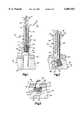
- a suture anchor 20(FIG. 1) is formed of a material which absorbs body liquid when t he anchor is exposed to body liquid. As the material of the anchor 20 absorbs body liquid, the anchor expands from the initial volume of FIGS. 1-3 to the expanded volume of FIG. 4. As the material of the anchor 20 absorbs body liquid and expands, the volume of the anchor increases and an improved mechanical interlock is formed between the anchor and body tissue in which the anchor has been inserted. The improved interlock enables the anchor 20 to resist large tension forces in a suture 32 without pulling out of body tissue 22.
- the anchor 20could be completely formed of material which absorbs body liquid.
- th e anchorcould be partially formed of material which absorbs body liquid and partially formed of material which does not absorb body liquid.
- the material which does not absorb body liquidmay be provided with projections which are forced into the body upon expansion of the material which absorbs body liquid. This would result in at least two different interlocks being obtained between the anchor and the body tissue, that is, a n interlock due to expansion of the material which absorbs body liquid and an interlock due to engagement of projections on the material which does not absorb body liquid with the body tissue.
- the suture anchor 20is entirely formed of material which absorbs body liquid.
- the suture anchor 20was formed of a polymeric material which absorbs body liquid.
- the polymeric materialmay be either a copolymer or a dipolymer.
- the polymeric materialmay be hydrophilic.
- the polymeric materialmay be cellulose, petroylglutamic acid, high purity carboxymethylcellulos e, a collagen, or polylactide. It is believed that a ceramic as found in hydroxyapatite composites with polyethylene, polylactide or polyhydroxybutyrate may be utilized to form the anchor 20.
- the suture anchor 20could be formed of other known materials which absorb body liquid.
- the hydrophilic material forming the anchor 20attracts body liquid under the influence of molecular attraction and establishes molecular linkages with the body liquid.
- the material forming the anchor 20is body liquid permeable.
- the body liquidenters minute cavities in the porous material forming the anchor 20 under the influence of capillary action.
- the attractive forces between molecules of the body liquid and molecules of the material forming the anchor 20holds the body liquid in the minute cavities in the material forming the anchor.
- the suture anchor 20has a tubular cylindrical configuration.
- the suture anchor 20has a tubular wall 24 formed of material which absorbs body liquid.
- the tubular wall 24has a cylindrical outer side surface 26 which is coaxial with a cylindrical inner side surface 28.
- the cylindrical inner side surface 28forms a cylindrical passage 30 which extends axially through the center of the suture anchor 20.
- the wall 24 of the suture anchor 20is formed as one piece of a porous hydrophilic polymer which absorbs body liquid.
- the anchor 20may be shaped or ground to any one of many different axially tapering or flaring configurations, such as those disclosed in U.S. Pat. No. 5,403,348. It is believed that it may be preferred to form the anchor 20 with either a cylindrical configuration or a polygonal configuration.
- tubular cylindrical suture anchor 20could be of many different sizes, it is believed that the suture anchor may preferably have a length or axial extent of between 2 and 4 millimeters.
- the cylindrical outer side surface 26 of the suture anchor 20may have a diameter of between 1 and 2 millimeters.
- the cylindrical inner side surface 28 of the passage 30 in the anchor 20may have a diameter of 1/2 to 1 millimeter.
- the suture anchor 20could be formed with many different dimensions and/or shapes if desired.
- a suture 32is inserted into the passage 30 in the suture anchor 20.
- the suture 32includes a portion or leg 34 which extends away from a flat annular trailing end surface 36 of the anchor 20.
- the suture 32has a second portion or leg 38 which extends across a flat annular leading end surface 40 of the anchor 20.
- the leg 38 of the suture 32extends along the cylindrical outer side surface 26 of the anchor 20 to a location adjacent to and spaced from the leg portion 34 of the suture 32.
- a relatively short portion 44 of the suture 32interconnects the leg portions 34 and 38 and is disposed in the passage 30 in the suture anchor 20.
- An inserter assembly 60is used to position the suture anchor 20 and a portion of the suture 32 in a patient's body tissue 22.
- the inserter assembly 60includes a cylindrical tubular outer sleeve 66 having a cylindrical central passage 68 in which the anchor 20 is disposed.
- the inserter 60also includes a cylindrical tubular inner sleeve 72 which is telescopically received in the outer sleeve 66.
- the tubular inner sleeve 72has a conical tapered leading end portion 74 which engages an annular trailing end surface 36 of the anchor 20.
- the leg or portion 34 of the suture 32extends through a cylindrical passage 76 in the inner sleeve 72.
- the leg or portion 38 of the suture 32extends through the central passage 68 in the outer sleeve 66 along a path which extends between the inner and outer sleeves.
- the leg or portion 38 of the suture 32could extend along the outside of the outer sleeve 66. If desired, one of the legs or portions 34 or 38 of the suture could be omitted. If this was done, the suture 32 could be tied or otherwise secured to the anchor 20.
- the anchor 20may be inserted into a human patient's body at many different locations.
- the anchor 20may be inserted into either hard or soft tissue.
- the anchor 20is being inserted into bone tissue 22 in a patient's body.
- a cylindrical recess 80is formed in the bone tissue 22 of the patient's body by drilling or other methods.
- the recess 80extends through a hard compact outer layer 82 of the patient's bone tissue 22 into the relatively porous inner or cancellous tissue 84.
- the cylindrical inner sleeve 72is moved axially downward (as viewed in FIG. 1) to apply force against a relatively small area on the annular trailing end surface 36 of the anchor 20.
- the leg 38 of the suture 32is tensioned to apply force against an annular leading end surface 40 of the anchor 20.
- the bevelled leading end 74 of the inner sleeve 72is pressed against the trailing end surface 36 of the anchor.
- the suture 32is then tensioned to secure a member, such as body tissue 90, in place.
- the member or body tissue 90may be soft tissue, or a ligament, or a tendon, or other body tissue. If desired, the suture 32 may be used to secure other members, such as an implant or splint, in place relative to the patient's body tissue 22.
- the sutureis tensioned to transmit force between the anchor 20 and a member to be held in place.
- FIGS. 1-3One specific known inserter assembly 60 and method of inserting a suture anchor 20 into a patient's body tissue has been illustrated in FIGS. 1-3.
- This specific inserter assembly and the method of inserting the anchor 20are the same as is disclosed in U.S. Pat. No. 5,403,348 issued Apr. 4, 1995 and entitled "Suture Anchor".
- many different known types of inserter assembliescould be utilized to install the suture anchor 20 with many different methods in a patient's body tissue.
- the inserter assembly and method disclosed in U.S. Pat. No. 5,464,426 issued Nov. 7, 1995 and entitled “Method of Closing Discontinuity in Tissue"could be utilized if desired.
- other known apparatus and methodscould also be utilized if desired.
- the suture anchor 20absorbs body liquid and expands once the suture anchor has been inserted into the body tissue 22.
- the expansion of the suture anchor 20improves the initial interlock between the anchor and body tissue 22.
- the initial interlock between the anchor 20 and body tissue 22is obtained by pivoting the anchor in the body tissue to the orientation shown in FIG. 3.
- the improved interlockis obtained by expanding the anchor 20, as shown in FIG. 4.
- the improved interlockallows relatively large tension forces to be transmitted through the suture 32 between the anchor 20 and a member to be held in place by the suture.
- the suture anchor 20expands in all directions, from the initial size illustrated in FIG. 3 to a relatively large expanded size illustrated in FIG. 4, shortly after the suture anchor has been inserted into the body tissue 22.
- the suture anchoris exposed to body liquids, indicated schematically at 98 in FIG. 4.
- the body liquids 98are drawn into the suture anchor 20 due to the affinity of the polymeric material forming the suture anchor 20 for body liquids.
- the anchorexpands in a substantially uniform manner in all directions.
- the anchor 20swells both radially and axially.
- Substantially uniform expansion of the entire outer side surface area of the suture anchor 20occurs as body liquids 98 are absorbed by the anchor.
- the extent of expansion of the suture anchor 20will depend upon the specific characteristics of the material from which the suture anchor is formed and may vary between 10 and 50 percent by volume. Of course, the extent of expansion of the anchor 20 will be a function of the force applied against the outer side surface of the anchor by the body tissue 22.
- the size of the anchor 20increases. As the size of the anchor 20 increases, the outer side surface of the anchor presses both axially and radially outward against the body tissue 22. As the anchor 20 expands and presses against the body tissue, the body tissue is displaced by the anchor. Thus, the outer side surface of the anchor 20 applies force against the body tissue 22 and moves the body tissue to make room for the anchor as the anchor expands. If the anchor 20 encounters a localized area of high resistance to expansion in the body tissue, the anchor will expand around the localized area and may even shift in the body tissue 22.
- the expansion of the anchor 20 as it absorbs the body liquids 98results in an increasing mechanical interlocking action between the anchor 20 and the body tissue 22.
- the anchorexpands to improve the mechanical interlock between the anchor and the body tissue 22.
- the improved interlock between the anchor 20 and body tissue 22allows relatively large tension forces to be transmitted through the suture 32 without pulling the anchor out of the body tissue.
- the anchor 20was pivoted from the orientation shown in FIG. 1 through the orientation shown in FIG. 2 to the orientation shown in FIG. 3 to obtain an initial mechanical interlock between the anchor and body tissue 22.
- the anchoris not pivoted from its initial orientation to obtain an initial mechanical interlock.
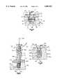
- the anchoris merely positioned in the body tissue and expanded in all directions by absorbing body liquid. The expansion of the anchor results in the formation of an interlock between the anchor and the body tissue. Since the embodiment of the invention illustrated in FIGS. 5 and 6 is generally similar to the embodiment of the invention illustrated in FIGS. 1-4, similar numerals will be utilized to designate similar components, the suffix letter "a" being associated with the numerals of FIGS. 5 and 6 in order to avoid confusion.
- the suture anchor 20ahas the same construction and is formed of the same hydrophilic polymeric material as the suture anchor 20 of FIGS. 1-3.
- the suture anchor 20a(FIG. 5) has a cylindrical tubular configuration.
- the suture anchor 20ahas a cylindrical outer side surface 26a.
- a cylindrical central passage 30aextends through the suture anchor 20a between opposite annular end surfaces 36a and 40a of the suture anchor 20a.
- a suture 32ahas a leg 34a which extends through a passage 76a formed in an inner sleeve 72a.
- a second leg 38a of the suture 32aextends through a central passage 68a and a tubular outer sleeve 66a.
- the leg 38a of the suture 32aextends between a cylindrical inner side surface 68a of the inner sleeve 72a and a cylindrical inner side surface of the outer sleeve 66a.
- the anchor 20amay be inserted into a patient's body at many different locations.
- the anchor 20amay be inserted into either hard or soft tissue.
- the anchoris being inserted into bone tissue 22a in a patient's body with the inserter assembly 60a.
- a recess 80ais formed in the bone tissue 20a of the human patient's body by drilling or other methods.
- the cylindrical recess 80aextends through the hard compact outer layer 82a of the patient's bone tissue 20a into the relatively porous inner or cancellous tissue 84a.
- the inner sleeve 72ais moved axially downward (as viewed in FIG. 5) to apply force against the trailing end surface 36a of the anchor 20a.
- the inner sleeve 72ahas a cylindrical leading end portion 74a which applies a substantially uniform force over substantially the entire flat annular trailing end surface 36a of the anchor 20a. Therefore, the anchor 20a is not pivoted but is merely moved straight into the recess 80a.
- the anchor 20aOnce the anchor 20a has been positioned in the recess 80a, the anchor absorbs body liquid 98a and increases in volume as the liquid is absorbed. This results in the anchor expanding in all directions from the initial size of FIG. 5 to a relatively large expanded size illustrated in FIG. 6. As the anchor 20a expands, its size increases by 10 to 50 percent by volume.
- the anchor 20ais porous and is formed of a hydrophilic material.
- the body liquid 98ais drawn into openings in the porous material of the anchor 20a by the affinity of the porous material forming the anchor for the body liquid. The attractive forces between the material forming the anchor 20a and the body liquid holds the body liquid in the anchor.
- the outer surfaces on the anchorpress radially and axially against the body tissue 22a.
- Substantially uniform expansion of the anchor 20aforms a secure mechanical interlock with the body tissue. This interlock enables tension forces to be transmitted through the suture 32a between the anchor 20a and a member, such as the body tissue 90a.
- the cancellous tissue 84ais compressed and the size of the portion of the recess 80a in the cancellous tissue 84a is increased.
- the diameter of the cylindrical anchor 20aincreases from a diameter which is just slightly less than the size of the portion of the recess 80a which extends through the hard compact outer layer 82a of the bone tissue 22a to a diameter which is greater than the diameter of the portion of the recess 80a extending through the hard compact outer layer 82a of bone tissue. This results in the anchor 20a being locked in place in the body tissue 22a.
- the suture 32acan then be used to secure a member 90a in place in the manner illustrated schematically in FIG. 6.
- the member 90amay be soft body tissue, or a ligament, or a tendon, or other body tissue. If desired, the suture 32a may be used to secure an implant or splint in place relative to the patient's body 22a.
- the interlock between the anchor 20a and body tissue 22aenables substantial tension force to be transmitted through the suture 32a without pulling the anchor out of the body tissue.
- the expansion of the anchor 20ahas been schematically illustrated in FIG. 6 as being uniform in all directions. This will be the case when the body tissue 22a applies uniform forces against all sides of the anchor 20a. However, the body tissue 22a may provide nonuniform resistance to expansion of the anchor 20a. When this occurs, the anchor 20a may shift in the body tissue 22a under the influence of forces applied against the body tissue as the anchor expands. In addition or alternatively, the anchor 20a may expand in a nonuniform manner.
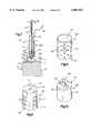
- the anchor 20has a generally cylindrical configuration and is formed entirely of a hydrophilic polymeric material which absorbs body liquid.
- the anchor illustrated in FIGS. 1-4due to its relatively blunt leading end portion, is particularly well adapted for positioning in preformed recesses in body tissue.
- the anchor illustrated in FIG. 7the anchor has a sharp or pointed leading end portion to facilitate forming an opening in imperforate body tissue. Since the embodiment of the invention illustrated in FIG. 7 is generally similar to the embodiment of the invention illustrated in FIGS. 1-4, similar numerals will be utilized to designate similar components, the suffix letter "b" being associated with the numerals of FIG. 7 to avoid confusion.
- the tubular cylindrical suture anchor 20bhas a generally cylindrical outer side surface 26b which is coaxial with a cylindrical inner side surface 28b.
- the cylindrical inner side surface 28bforms a portion of a passage 30b which extends through the anchor 20b.
- a second cylindrical side surface 110has a central axis which extends perpendicular to the central axis of the cylindrical side surface 28b.
- the cylindrical side surface 110intersects the cylindrical side surface 28b and extends radially outward from the cylindrical side surface 28b.
- the cylindrical side surfaces 28b and 110cooperate to form the passage 30b with a generally L-shaped configuration.
- a suture 32bis inserted into the passage 30b in the suture anchor 20b.
- the suture 32bincludes a portion or leg 34b which extends away from a flat annular trailing end surface 36b of the anchor 20b.
- the suture 32bhas a second portion or leg 38b which extends along the cylindrical outer side surface 26b of the anchor 20b and along the cylindrical inner side surface 68b of the outer sleeve 66b.
- a relatively short portion 44b of the suture 32binterconnects the leg portions 34b and 38b and is disposed in the passage 30b in the suture anchor 20b.
- An inserter assembly 60bis used to position the suture anchor 20b and a portion of the suture 32b in a patient's body tissue 22b.
- the inserter assembly 60bincludes a generally cylindrical tubular outer sleeve 66b having a central passage 68b in which the anchor 20b is disposed.
- the inserter 60balso includes a tubular inner sleeve 72b which is telescopically received in the outer sleeve 66b.
- the tubular inner sleeve 72bhas a conical tapered leading end portion 74b which engages the trailing end surface 36b of the anchor 20b.
- the anchor 20bhas a leading end portion 112 with a generally conical configuration.
- the leading end portion 112 of the anchor 20bis adapted to form an opening in an imperforate outer side surface 114 of the patient's body tissue 22b.
- the leading end portion 112 of the anchor 20bfacilitates moving the anchor into the body tissue 22b under the influence of force applied against the trailing end surface 36b of the anchor 20b by the tubular inner sleeve 72b.
- the conical leading end portion 112 of the anchor 20bis formed by a conical layer of a relatively hard polymeric material.
- the polymeric material forming the leading end portion 112may be biodegradable if desired.
- the anchor 20bhas a cylindrical body portion or wall 116 which is disposed in a coaxial relationship with the leading end portion 112.
- the cylindrical body portion 116is formed of a hydrophilic polymeric material which absorbs body liquid when exposed to the body liquid.
- the cylindrical body portion 116is formed of the same material as the anchor 20 of FIGS. 1-4. As the body portion 116 of the anchor 20b absorbs body liquid, the body portion of the anchor expands radially and axially to interlock with the body tissue 22b.
- the leading end portion 112is formed of a rigid polymeric material which does not absorb body liquid.
- the leading end portion 74b of the tubular inner sleeve 72bis tapered so that it applies force against the trailing end surface 36b of the anchor 20b at a relatively small area on the trailing end surface.
- the concentrated application of force to the trailing end surface 36b of the anchor 20bfacilitates pivoting movement of the anchor in the body tissue 22b upon tensioning of the leg 38b of the suture 32b.
- the body portion 116 of the anchorwill absorb body liquid, such as blood or other fluids.
- body liquidsuch as blood or other fluids.
- the body portionexpands in all directions and presses against the body tissue 122.
- body tissueis displaced and the mechanical interlock with the anchor 20b is enhanced.
- the anchor 20bis mechanically interlocked with the body tissue 122 by both pivotal movement of the anchor to a sidewise orientation and expansion of the anchor as it absorbs body liquids.
- the improved interlock obtained by expanding the anchor 20benables relatively large tension forces to be transmitted between a member (not shown) and the anchor 20b through the suture 32b.
- the anchoris formed entirely of material which absorbs body liquid when it is exposed to the body liquid.
- a portion of the anchoris formed of material which absorbs body liquid and another portion of the anchor is formed of material which does not absorb body liquid.
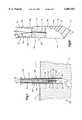
- the material which does not absorb body liquidhas projections which engage body tissue to enhance an interlock between the anchor and the body tissue. Since the embodiment of the invention illustrated in FIG. 8 is generally similar to the embodiment of the invention illustrated in FIGS. 1-4, similar numerals will be utilized to designate similar components, the suffix letter "c" being associated with the numerals of FIG. 8 in order to avoid confusion.
- An anchor 20c(FIG. 8) has a tubular cylindrical configuration.
- a suture(not shown) extends through a central passage 30c in the anchor 20c in the same manner as illustrated in FIG. 1 for the anchor 20.
- the anchor 20c(FIG. 8) has a body portion 116c which is formed of a hydrophilic polymeric material which absorbs body liquid when exposed to the body liquid.
- the anchor 20cincludes a plurality of identical retaining portions 130, 132 and 134.
- the retaining portions 130, 132 and 134are formed of a relatively hard polymeric material which does not absorb body liquid.
- the retaining portions 130, 132 and 134may be biodegradable if desired.
- the retaining portions 130, 132 and 134 and a plurality of ribs or projections 138which extend outward from the retaining portion.
- the body portion 116cabsorbs body liquid.
- the body portion 116c of the anchor 20cexpands radially and axially outward to enhance the mechanical interlock with the body tissue.
- the retaining portions 130, 132 and 134are moved radially outward away from the central axis of the anchor 20c. This presses the ribs 138 on the retaining portions 130, 132 and 134 into the body tissue to further enhance the mechanical interlock between the anchor and the body tissue.
- the ribs 138have been shown in FIG. 8 as having a generally arcuate configuration and a generally smooth outer side surface, it is contemplated that the ribs could have barbs or other projections which would impale the body tissue as the body portion 116c of the anchor 20c absorbs body liquid and expands. Of course, this would further enhance the mechanical interlock between the anchor 20c and the body tissue.
- the anchorhas a generally flat annular leading end portion.
- the anchor 20ccould be provided with a conical leading end portion, similar to the conical leading end portion 112 on the anchor 20b of FIG. 7. If the anchor 20c were to be provided with a conical leading end portion, it is contemplated that the retaining portions 130, 132 and 134 could be extended in an axial direction to form the conical leading end portion as three separate segments. As the body portion 116c of the anchor 20c absorbs body liquid and expands, the retaining portions 130, 132 and 134 would move radially outward away from each other and the leading end portion of the anchor would expand.
- a relatively strong interlockis obtained between the anchor 20c and body tissue.
- This interlockis obtained by changing the orientation of the anchor 20c relative to the body tissue, in the manner illustrated for the anchor 20 in FIG. 2.
- the interlockis obtained by expansion of the anchor 20c as the body portion 116c absorbs body liquid.
- the interlockis also obtained by engagement of the ribs 138 with body tissue. The result is a strong interlock which enables the anchor 20c to resist very large tension forces transmitted to the anchor through a suture.
- the anchoris formed entirely of material which expands when it is exposed to body liquid.
- the anchoris formed by a core of material which expands upon being exposed to body liquid and an elastic jacket which encloses the core. Since the embodiment of the invention illustrated in FIG. 9 is generally similar to the embodiment of the invention illustrated in FIGS. 1-4, similar numerals will be utilized to designate similar components, the suffix letter "d" being associated with the numerals of FIG. 9 in order to avoid confusion.
- An anchor 20d(FIG. 9) has a cylindrical configuration.
- the anchor 20dincludes a cylindrical core 144 which is enclosed by a tubular cylindrical jacket 146.
- a passage 30dextends through both the core 144 and the jacket 146.
- the passage 30dextends diametrically through the core 144 and the jacket 146 and has a cylindrical configuration.
- a suture(not shown) is positioned in the passage 30d. The suture may be tied off at one end of the passage or may extend through the passage so that legs of the suture extend along opposite sides of the jacket 146.
- the jacket 146is provided with a plurality of circular openings 150 which extend through the jacket.
- the openings 150enable body liquid to pass through the jacket into the core 144.
- the jacket 146is formed of an elastic polymeric material which is easily stretched.
- the core 144is formed of a material which absorbs body liquid upon being exposed to the body liquid.
- the core 144was formed of a hydrophilic polymeric material which is the same as the material forming the anchor 20 of FIGS. 1-4.
- the entire anchor 20dis exposed to body liquid.
- the body liquidpasses through the openings 150 and is absorbed by the core 144.
- the core 144absorbs body liquid, the core expands and stretches the jacket 146.
- the anchor 20dhas been shown as having a generally cylindrical configuration with flat annular end surfaces, it is contemplated that the anchor could be provided with a conical leading end portion, similar to the conical leading end portion 112 of the anchor 20b of FIG. 7.
- the conical leading end portioncould be formed either as a portion of the jacket 46 or separately from the jacket. It is believed that it may be preferred to form a conical leading end portion for the anchor 20d separately from the jacket 146 to enable the leading end portion to be formed of a hard material which is not readily stretched and which is capable of piercing an imperforate surface of body tissue.
- the jacket 146is formed of a material which is resiliently stretched when the core 144 absorbs body liquid and expands. It is contemplated that the size of the jacket 146 could be increased in other ways to accommodate expansion of the core. For example, releasable tucks could be formed in the jacket. Upon expansion of the core, stitches or other devices holding the tucks would be released under the influence of force applied against the jacket by the core.
- the anchors illustrated in FIGS. 1-9all have passages through which the suture extends.
- the anchorhas an eyelet through which the suture extends. Since the embodiment of the invention illustrated in FIG. 10 is generally similar to the embodiment of the invention illustrated in FIGS. 1-9, similar numerals will be utilized to designate similar components, the suffix letter "e" being associated with the embodiment of the invention illustrated in FIG. 10 to avoid confusion.
- An anchor 20ehas a solid cylindrical body portion 116e.
- the body portion 116e of the anchor 20eis formed of a hydrophilic polymeric material which absorbs body liquid when exposed to the body liquid.
- the material forming the body portion of the anchor 20eis the same as the material forming the anchor 20 of FIGS. 1-4. Upon absorbing body liquid, a portion 116e of the anchor 20e expands.
- the anchor 20eis provided with a trailing end portion 160 which is connected with a suture.
- the trailing end portion 160 of the anchor 20ehas a circular wall 162 which is fixedly connected with the body portion 116e of the anchor 20e.
- a passage 30eis formed in a projection 164 which extends axially outward from the end wall 162.
- the passage 30ereceives a suture.
- the suturemay be tied off on the projection 164 or may extend through the projection and have a pair of legs, corresponding to the legs 34 and 38 of the suture 32 of FIG. 1.
- the body portion 116eis exposed to body liquid. This results in the body portion 116e of the anchor 20e expanding radially and axially outward from the trailing end portion 160 to form a mechanical interlock with the body tissue.
- the anchorsare formed of a hydrophilic polymeric material which absorbs body liquid.
- the anchoris formed of cellular material which absorbs body liquid. Since the embodiment of the invention illustrated in FIG. 11 is generally similar to the embodiments of the invention illustrated in FIGS. 1-10, similar numerals will be utilized to designate similar components, the suffix letter "f" being associated with the numerals of FIG. 11 to avoid confusion.
- a suture anchor 20fhas a tubular cylindrical configuration when the anchor is in an unrestrained condition.
- the anchorWhen the suture anchor 20f is in an unrestrained condition, the anchor has a tubular wall 24f which has a cylindrical outer side surface 26f which is coaxial with a cylindrical inner side surface 28f of the anchor.
- the cylindrical inner side surface 28fforms a passage 30f which extends axially through the center of the suture anchor 20f when the anchor is in an unrestrained condition.
- the wall 24f of the suture anchor 20fis formed as one piece of resilient material containing a large number of cells which are expandable to absorb body liquid.
- the cellular material which forms the suture anchor 20fmay be a hydrophilic polymeric cellular material which absorbs body liquid.
- the anchor 20fmay be shaped to any one of many different axially tapering or flaring configurations or may have a polygonal configuration.
- a suture 32fis inserted into the passage 30f in the suture anchor 20f.
- the suture 32fincludes a leg portion 34f which extends away from a flat annular trailing end surface 36f of the anchor 20f.
- the suture 32fhas a second portion or leg 38f which extends across a flat annular leading end surface 40f of the anchor 20f.
- the leg 38f of the suture 32fextends along the cylindrical outer side surface 26f.
- a relatively short portion 44f of the suture 32finterconnects the leg portion 34f and 38f and is disposed in the passage 30f in the anchor 20f.
- An inserter assembly 60fis used to position the anchor 20f and a portion of the suture 32f in a patient's body tissue 22f.
- the inserter assembly 60fincludes a cylindrical tubular outer sleeve 66f having a cylindrical passage 68f in which the anchor 20f is disposed.
- the inserter 60falso includes a cylindrical tubular inner sleeve 72f which is telescopically received in the outer sleeve 66f.
- the tubular inner sleeve 72fhas a cylindrical leading end portion 74f which engages the trailing end surface 36f of the anchor 20f.
- the leading end portion 74f of the tubular inner sleeve 72fhas an end wall 168 with a flat end surface which abuttingly engages the flat annular trailing end surface 36f on the anchor 20f.
- the two legs 34f and 36f of the suture 32fextend through a central opening formed in the end wall 168 at the leading end portion 74f of the inner sleeve 72f.
- the legs 34f and 38f of the suture 32fextend through the tubular inner sleeve 72f to a location remote from the inserter assembly 60f. If desired, one of the legs 34f or 38f of the suture could be omitted. If this was done, the suture 32f could be tied or otherwise secured to the anchor 20f.
- the anchor 20fmay be inserted into a human patient's body at many different locations.
- the anchor 20fmay be inserted into either hard or soft tissue. In the situation illustrated schematically in FIG. 11, the anchor 20f is being inserted into soft body tissue in a patient's body.
- a leading end portion 170 of the outer sleeve 60fhas an axially tapered or pointed configuration.
- the pointed configuration of the leading end portion 170 of the outer sleeve 60fenables the leading end portion of the outer sleeve to form an opening in an imperforate outer side surface 114f of the patient's body tissue 22f.
- the pointed leading end portion 170 of the outer sleeve 60ffacilitates moving the outer sleeve 60f into the body tissue 22f under the influence of force manually applied against an outer end portion of the outer sleeve 60f.
- the pointed leading end portion 170 of the outer sleeve 66fis pressed against the imperforate outer side surface 114f of skin or other tissue 120f.
- the pointed leading end portion of the outer sleeve 66fpierces the imperforate outer surface 114f of the skin 120f and enters soft body tissue 122f disposed beneath the skin.
- the outer sleeve 66fis forced into the soft body tissue 22f for a desired distance corresponding to the distance which the suture anchor 20f is to be inserted into the body tissue.
- the inner sleeve 72fis then pressed downward (as viewed in FIG. 11) to move the suture anchor 20f to the leading end portion 170 of the outer tubular member 66f.
- the inner side surface 68f of the tubular outer member 66fapplies force against the outer side surface 26f of the anchor 20f to maintain the anchor in the compressed condition shown in FIG. 11.
- the outer tubular member 66fis then moved axially upward (as viewed in FIG. 11) relative to the stationary inner tubular member 72f. This results in the anchor 20f being ejected from the outer tubular member 66f into the body tissue 22f.
- a pointed membersuch as a trocar, could be inserted through the outer sleeve 66f to pierce the surface 114f and body tissue 22f. If this was done, the inner sleeve 72f and anchor 20f would be removed from the outer sleeve 66f to provide room for the pointed member. After the body tissue has been pierced by the pointed member, the pointed member would be withdrawn from the outer sleeve 66f and the inner sleeve 72f and compressed anchor 20f inserted into the outer sleeve.
- the anchor 20fis formed of a resilient cellular material. Prior to insertion of the anchor 20f into the outer sleeve 66f, the cellular material of the anchor 20f is resiliently compressed from a relatively large unrestrained size to a compacted size illustrated in FIG. 11.
- the unrestrained size of the suture anchor 20fmay be 2 to 20 times as large as the size illustrated in FIG. 11.
- the passage 30fwhich extends through the anchor 20f when the anchor is in its unrestrained condition, is collapsed tightly inward against the portion 44f of the suture 32f.
- the anchor 20fis resiliently compressed from its unrestrained condition, the cells in the anchor are collapsed.
- the anchor 20fis resiliently compressed from an unrestrained condition to the compacted or compressed condition of FIG. 11 in much the same manner as in which a sponge may be compressed.
- the compressed anchor 20fwith the suture 32f extending through the anchor and the inner sleeve 72f, is inserted into the outer sleeve 66f.
- the inner sleeve 72fthen pushes the compressed anchor axially downward (as viewed in FIG. 11) into the outer sleeve as the telescopic relationship between the inner and outer sleeves is increased.
- the inner side surface 68f of the outer sleeveapplies force against the outer side surface 26f of the anchor to hold the anchor in its compressed condition.
- the force holding the anchor 20f in a compressed conditionis removed from the outer side surface 26f of the anchor.
- the natural resilience of the cellular material forming the anchor 20fcauses the anchor to expand.
- the anchor 20fAs the anchor 20f expands, the anchor applies force against the soft body tissue 122f and increases the size of the cavity which was originally formed by the outer sleeve 66f of the inserter assembly 60f. As the anchor 20f expands, it applies force against the soft body tissue 122f and displaces the soft body tissue. Thus, the outer side surface 26f of the anchor 20f is pressed against the soft body tissue 122f and moves the soft body tissue as the anchor expands radially outward.
- the cells in the anchorare expanded from a collapsed condition to an expanded condition.
- body liquidsare drawn into the cells.
- the anchor 20fabsorbs body liquid as it expands.
- the anchor 20fis formed of a resilient polymeric material having an open cell, sponge-like construction.
- the cellsare collapsed.
- the anchor 20fexpands in the body tissue 22f, the cells expand. Since the anchor 20f has an open cellular construction, body liquid can flow into the cells as the anchor expands.
- the expanded anchoris substantially larger than the opening which was formed in the body tissue by insertion of the outer sleeve 66f into the body tissue.
- the anchormay not expand fully back to its unrestrained size.
- the viscoelastic nature of the body tissuecauses the body tissue to come together and close off the passage which was formed by the insertion of the outer sleeve 66f into the body tissue.
- the body tissuewill move inward and grip the legs or portions 34f and 38f of the suture 32f.
- the anchor 20fwill fill a cavity formed in the body tissue 22f by expansion of the anchor.
- the expansion of the anchor 20f in the body tissueresults in the formation of an interlock between the anchor and the body tissue to prevent the anchor from being pulled out of the body tissue under the influence of tension applied to the suture 32f.
- the suture 32fmay be used to position a member which is body tissue, in the manner similar to that illustrated in FIGS. 3 and 4, or may be used to position a splint or implant member relative to the body tissue. Since the expanded anchor 20f has a firm interlock with the body tissue 122f, tension forces transmitted through the suture 32f between the anchor 20f and a member held in place by the suture will not pull the anchor 20f out of the body tissue.
- the compressed suture anchor 20fis being inserted into a solid mass of soft body tissue 122f.
- the suture anchor 20fcould be inserted into either a natural or artificial body cavity. If this was done the suture anchor 20f would expand to at least partially fill the body cavity.
- the anchor 20fmoves through the open end portion 170 of the outer sleeve 66f into the body tissue 22f.
- the outer sleevehas a closed pointed end portion and the anchor is moved from the outer sleeve at a location immediately behind the pointed end portion of the outer sleeve. Since the embodiment of the invention illustrated in FIG. 12 is generally similar to the embodiment of the invention illustrated in FIG. 11, similar numerals will be utilized to designate similar components, the suffix letter "g" being associated with the numerals of FIG. 12 to avoid confusion.
- An anchor 20ghas the same construction and is formed of the same resilient open cell material as the anchor 20f of FIG. 11.
- a suture 32ghas a leg or portion 34g which extends from a flat annular trailing end surface 36g of the cylindrical anchor 20g.
- a second leg or portion 38g of the suture 32gextends from a flat annular leading end surface 40g of the anchor 20g.
- a portion 44g of the suture 32gextends through the anchor and interconnects the legs or portions 34g and 38g.
- the two legs or portions 34g and 38g of the suture 32gextend through a cylindrical central passage in an outer sleeve 72g of an inserter assembly 60g.
- the inner sleeve 72gis disposed in a telescopic relationship with a cylindrical outer sleeve 66g of the inserter assembly 60g.
- the inner sleeve 72gcooperates with the outer sleeve 66g in the same manner as previously explained in conjunction with the inserter assembly of FIG. 11.
- the outer sleeve 66ghas a solid pointed end portion 170g with a generally conical configuration.
- the pointed end portion 170gis utilized to pierce an imperforate surface of body tissue in much the same manner as in which the end portion 170 of the outer sleeve 66f of the inserter assembly 60f (FIG. 11) is used to pierce an imperforate surface 114f of the body tissue 22f.
- the outer sleeve 66ghas a generally oval opening 180 in a cylindrical outer side surface 182 of the outer sleeve 66g.
- the opening 180is connected with a central passage 68g.
- the passage 68gextends from an open upper (as viewed in FIG. 12) end portion of the outer sleeve 66g to the solid pointed leading end portion 170g.
- the inner sleeve 72gis moved axially downward (as viewed in FIG. 12) and the anchor 20g is forced along an arcuate cam surface 184 leading to the opening 180.
- the leading end 40g of the anchor 20gapplies force against the body tissue to displace the body tissue and provide space for the anchor.
- the orientation of the anchor 20gchanges from the orientation shown in FIG. 12 to an orientation similar to the orientation of the anchor 20 in FIG. 3.
- This pivotal movement of the anchor 20gresults in the anchor moving from an initial orientation in which a central axis of the anchor extends parallel to and is coincident with a central axis of the outer sleeve 66g to an orientation in which the central axis of the anchor 20g extends perpendicular to the central axis of the outer sleeve 66g.
- the anchor 20gAs the anchor 20g exits from the passage 68g in the outer sleeve 66g. the anchor 20g expands under the influence of its own natural resilience and further displaces body tissue. Once the inner sleeve 72g has been moved downward to the maximum extent possible, that is, to a position in which the leading end of the inner sleeve 72g engages the cam surface 184, the inner and outer sleeves are withdrawn together from the body tissue. As this occurs, engagement of the anchor 20g with the body tissue causes the trailing end portion of the anchor to move out of the passage 68g in the outer sleeve 66g.
- the pointed leading portion 170 of the outer sleevemoves upward (as viewed in FIG. 12), past the anchor 20g.
- the anchor 20gexpands into the space previously occupied by the leading end portion 170g of the outer sleeve 66g.
- the visco-elastic body tissuecloses around the anchor 20g and the legs 34g and 38g of the suture 32g.
- the anchor 20gAs the anchor 20g is forced from the outer sleeve 66g into the body tissue and expands, cells in the anchor 20g also expand. As the cells in the anchor 20g expand, body liquid is drawn into and at least partially fills the cells in the anchor.
- the anchor 20ghas an open cellular construction, similar to the construction of a sponge. The anchor 20g is resiliently compressed prior to insertion into the outer sleeve 66g so that the cells in the anchor 20g are resiliently collapsed until the anchor is allowed to expand as it is forced out of the side opening 180 in the outer sleeve 66g.
- the general configuration of the anchor 20is illustrated as being maintained constant.
- the anchor 20has a cylindrical tubular configuration with a linear central axis.
- the configuration of the anchoris changed while the anchor is in a patient's body tissue. Since the embodiment of the invention illustrated in FIG. 13 is generally similar to the embodiment of the invention illustrated in FIGS. 1-4, similar numerals will be utilized to designate similar components, the suffix letter "h" being associated with the numerals of FIG. 13 to avoid confusion.
- a suture anchor 20hhas the same construction and is formed of the same hydrophilic polymeric material as the suture anchor 20 of FIGS. 1-3.
- the suture anchor 20h(FIG. 13) has a cylindrical tubular configuration.
- the suture anchor 20hhas a cylindrical outer side surface 26h.
- a cylindrical central passage(not shown) extends through the suture anchor 20h between opposite annular end surfaces 36h and 40h of the suture anchor 20h.
- a suture 32hhas a leg 34h which extends from an annular end surface 36h of the anchor 20h.
- a second leg 38h of the suture 32hextends from the opposite end surface 40h of the anchor 20h.
- the anchor 20his inserted into body tissue 20h in the same manner as in which the anchor 20f of FIG. 11 is inserted into the body tissue 22f.
- an inserter assemblysimilar to the inserter assembly 60f of FIG. 11, is used to position the anchor 20h in the body tissue 22h.
- the inserter assemblymay include a tubular outer sleeve, corresponding to the sleeve 66f of FIG. 11 and a tubular inner sleeve, corresponding to the inner sleeve 72f of FIG. 11.
- the inner sleeve 72fis provided with a conical leading end portion having a configuration corresponding to the configuration of the leading end portion 74 (FIG. 1) of the inner sleeve 72. This enables the inserter assembly to pivot the suture anchor 20h to the position shown in FIG. 13.
- the outer sleeve of the inserter assemblywhich is used to position the anchor 20h in the body tissue 22h has a pointed leading end portion, corresponding to the pointed leading end 170 of the outer sleeve 66f of the inserter assembly 60f of FIG. 11.
- the pointed leading end of the outer sleeve of the inserter assemblywas used to pierce the imperforate outer side surface 114h of skin 120h and to enter soft body tissue 122h.
- the opposite legs 34h and 38h of the suture 32hwere tensioned. This resulted in the suture 32h applying force against the opposite flat annular end surfaces 36h and 40h of the anchor 20h.
- the force applied to opposite ends of the anchor 20h by the suture 32hpulled the outer side surface 26h of the anchor against the body tissue 122h.
- the force applied against opposite ends of the anchor 20h by the suture 32hcaused the suture to bend from an initial configuration to the deflected configuration shown in FIG. 13.
- the anchor 20hWhen the anchor 20h was in the initial configuration, the anchor 20h had a straight longitudinal central axis, the same as the anchor 20 of FIGS. 1-3. However, tensioning the suture 32h caused the legs 34h and 38h of the suture to apply force against opposite ends of the anchor 20h and pull the anchor against the body tissue 122h. As this occurred, the anchor was deflected to the arcuate configuration illustrated in FIG. 13. Since the anchor 20h is formed of the same hydrophilic polymeric material as the anchor 20 of FIGS. 1-3, the anchor 20h absorbs body fluid and expands in the body tissue 122h while the anchor has the deflected configuration illustrated in FIG. 13.
- the configuration of the anchor 20his changed from an initial configuration in which the anchor has a straight longitudinal central axis to a configuration in which the anchor has an arcuate longitudinal central axis by tensioning the suture 32h to apply force against opposite ends of the anchor.
- the configuration of the anchoris changed from an initial configuration to a deflected configuration by tensioning a suture which is connected with a central portion of the anchor. Since the embodiment of the invention illustrated in FIG. 14 is generally similar to the embodiment of the invention illustrated in FIG. 13, similar numerals will be utilized to designate similar components, the suffix letter "j" being associated with the numerals of FIG. 14 to avoid confusion.
- An anchor 20jhas an outer side surface 26j.
- the outer side surface 26jextends between opposite end surfaces 36j and 40j of the anchor.
- a suture 32jis connected with a central portion of the anchor 20j disposed between the opposite end surfaces 36j and 40j.
- the anchor 20jis formed of the same hydrophilic polymeric material as the anchor 20 of FIGS. 1-3.
- the anchor 20jis inserted into body tissue 22j in the same manner as described in connection with the embodiment of the invention illustrated FIG. 13.
- the anchor 20jPrior to insertion of the anchor 20j into the body tissue 22j, the anchor 20j has a solid cylindrical configuration with a straight longitudinal central axis. As the anchor 20j is inserted into the body tissue 22j and moved to the orientation shown in FIG. 14, the suture 32j is tensioned. Tensioning of the suture 32j presses the outer side surface 26j of the anchor 20j against the body tissue 22j. As this occurs, the anchor 20j is deflected from its initial configuration to the deflected configuration illustrated in FIG. 14. When the anchor 20j is in the deflected orientation, the longitudinal central axis of the anchor has an arcuate configuration.
Landscapes
- Health & Medical Sciences (AREA)
- Surgery (AREA)
- Life Sciences & Earth Sciences (AREA)
- Biomedical Technology (AREA)
- Nuclear Medicine, Radiotherapy & Molecular Imaging (AREA)
- Engineering & Computer Science (AREA)
- Rheumatology (AREA)
- Heart & Thoracic Surgery (AREA)
- Medical Informatics (AREA)
- Molecular Biology (AREA)
- Animal Behavior & Ethology (AREA)
- General Health & Medical Sciences (AREA)
- Public Health (AREA)
- Veterinary Medicine (AREA)
- Prostheses (AREA)
Abstract
Description
Claims (12)
Priority Applications (1)
| Application Number | Priority Date | Filing Date | Title |
|---|---|---|---|
| US09/259,759US6007567A (en) | 1996-08-19 | 1999-03-01 | Suture anchor |
Applications Claiming Priority (3)
| Application Number | Priority Date | Filing Date | Title |
|---|---|---|---|
| US08/699,553US5718717A (en) | 1996-08-19 | 1996-08-19 | Suture anchor |
| US08/964,167US5980559A (en) | 1996-08-19 | 1997-11-04 | Suture anchor |
| US09/259,759US6007567A (en) | 1996-08-19 | 1999-03-01 | Suture anchor |
Related Parent Applications (1)
| Application Number | Title | Priority Date | Filing Date |
|---|---|---|---|
| US08/964,167ContinuationUS5980559A (en) | 1996-08-19 | 1997-11-04 | Suture anchor |
Publications (1)
| Publication Number | Publication Date |
|---|---|
| US6007567Atrue US6007567A (en) | 1999-12-28 |
Family
ID=27106454
Family Applications (1)
| Application Number | Title | Priority Date | Filing Date |
|---|---|---|---|
| US09/259,759Expired - LifetimeUS6007567A (en) | 1996-08-19 | 1999-03-01 | Suture anchor |
Country Status (1)
| Country | Link |
|---|---|
| US (1) | US6007567A (en) |
Cited By (146)
| Publication number | Priority date | Publication date | Assignee | Title |
|---|---|---|---|---|
| WO2002005718A2 (en) | 2000-07-14 | 2002-01-24 | Opus Medical, Inc. | Suture anchor for attaching a suture to a bone part |
| US6520980B1 (en) | 2000-11-02 | 2003-02-18 | Opus Medical, Inc. | Method and apparatus for attaching connective tissues to bone using a self-locking knotless suture anchoring device |
| US6524317B1 (en) | 1999-12-30 | 2003-02-25 | Opus Medical, Inc. | Method and apparatus for attaching connective tissues to bone using a knotless suture anchoring device |
| US6582453B1 (en) | 2000-07-14 | 2003-06-24 | Opus Medical, Inc. | Method and apparatus for attaching connective tissues to bone using a suture anchoring device |
| US6585730B1 (en) | 2000-08-30 | 2003-07-01 | Opus Medical, Inc. | Method and apparatus for attaching connective tissues to bone using a knotless suture anchoring device |
| US6610079B1 (en) | 1999-12-14 | 2003-08-26 | Linvatec Corporation | Fixation system and method |
| US6652561B1 (en) | 2000-10-13 | 2003-11-25 | Opus Medical, Inc | Method and apparatus for attaching connective tissues to bone using a perforated suture anchoring device |
| US6660008B1 (en) | 2001-06-07 | 2003-12-09 | Opus Medical, Inc. | Method and apparatus for attaching connective tissues to bone using a suture anchoring device |
| US20040068267A1 (en)* | 2000-06-27 | 2004-04-08 | Fraser Harvie | Surgical procedures and instruments |
| US20060167481A1 (en)* | 2005-01-25 | 2006-07-27 | Esophyx, Inc. | Slitted tissue fixation devices and assemblies for deploying the same |
| US7189235B2 (en) | 1999-10-20 | 2007-03-13 | Anulex Technologies, Inc. | Spinal disc annulus reconstruction method and spinal disc annulus stent |
| US7556640B2 (en) | 2001-02-12 | 2009-07-07 | Arthrocare Corporation | Bone anchor device having toggle member for attaching connective tissues to bone |
| US7601165B2 (en) | 2006-09-29 | 2009-10-13 | Biomet Sports Medicine, Llc | Method and apparatus for forming a self-locking adjustable suture loop |
| US7608092B1 (en) | 2004-02-20 | 2009-10-27 | Biomet Sports Medicince, LLC | Method and apparatus for performing meniscus repair |
| US7615076B2 (en) | 1999-10-20 | 2009-11-10 | Anulex Technologies, Inc. | Method and apparatus for the treatment of the intervertebral disc annulus |
| US7615061B2 (en) | 2006-02-28 | 2009-11-10 | Arthrocare Corporation | Bone anchor suture-loading system, method and apparatus |
| US7637926B2 (en) | 2002-02-04 | 2009-12-29 | Arthrocare Corporation | Method and apparatus for attaching connective tissues to bone using a knotless suture anchoring device |
| US7674274B2 (en) | 2001-06-06 | 2010-03-09 | Arthrocare Corporation | Method and apparatus for attaching connective tissues to bone using a cortical bone anchoring device |
| US7682374B2 (en) | 2003-10-21 | 2010-03-23 | Arthrocare Corporation | Knotless suture lock and bone anchor implant method |
| US7749250B2 (en) | 2006-02-03 | 2010-07-06 | Biomet Sports Medicine, Llc | Soft tissue repair assembly and associated method |
| US7828850B2 (en) | 1999-10-20 | 2010-11-09 | Anulex Technologies, Inc. | Methods and devices for spinal disc annulus reconstruction and repair |
| US7857830B2 (en) | 2006-02-03 | 2010-12-28 | Biomet Sports Medicine, Llc | Soft tissue repair and conduit device |
| US7905904B2 (en) | 2006-02-03 | 2011-03-15 | Biomet Sports Medicine, Llc | Soft tissue repair device and associated methods |
| US7905903B2 (en) | 2006-02-03 | 2011-03-15 | Biomet Sports Medicine, Llc | Method for tissue fixation |
| US7909851B2 (en) | 2006-02-03 | 2011-03-22 | Biomet Sports Medicine, Llc | Soft tissue repair device and associated methods |
| US7922768B2 (en) | 1999-10-20 | 2011-04-12 | Anulex Technologies, Inc. | Spinal disc annulus reconstruction method and deformable spinal disc annulus stent |
| US7935147B2 (en) | 1999-10-20 | 2011-05-03 | Anulex Technologies, Inc. | Method and apparatus for enhanced delivery of treatment device to the intervertebral disc annulus |
| US7951201B2 (en) | 1999-10-20 | 2011-05-31 | Anulex Technologies, Inc. | Method and apparatus for the treatment of the intervertebral disc annulus |
| US7959650B2 (en) | 2006-09-29 | 2011-06-14 | Biomet Sports Medicine, Llc | Adjustable knotless loops |
| US7963972B2 (en) | 2007-09-12 | 2011-06-21 | Arthrocare Corporation | Implant and delivery system for soft tissue repair |
| US8088130B2 (en) | 2006-02-03 | 2012-01-03 | Biomet Sports Medicine, Llc | Method and apparatus for coupling soft tissue to a bone |
| US8105355B2 (en) | 2006-05-18 | 2012-01-31 | C.R. Bard, Inc. | Suture lock fastening device |
| US8105343B2 (en) | 2008-06-30 | 2012-01-31 | Arthrocare Corporation | Independent suture tensioning and snaring apparatus |
| US8118836B2 (en) | 2004-11-05 | 2012-02-21 | Biomet Sports Medicine, Llc | Method and apparatus for coupling soft tissue to a bone |
| US8128698B2 (en) | 1999-10-20 | 2012-03-06 | Anulex Technologies, Inc. | Method and apparatus for the treatment of the intervertebral disc annulus |
| US8128658B2 (en) | 2004-11-05 | 2012-03-06 | Biomet Sports Medicine, Llc | Method and apparatus for coupling soft tissue to bone |
| US8133258B2 (en) | 2006-08-03 | 2012-03-13 | Arthrocare Corporation | Method and apparatus for attaching connective tissues to bone using a knotless suture anchoring device |
| US8137382B2 (en) | 2004-11-05 | 2012-03-20 | Biomet Sports Medicine, Llc | Method and apparatus for coupling anatomical features |
| US8137381B2 (en) | 2007-04-25 | 2012-03-20 | Arthrocare Corporation | Knotless suture anchor having discrete polymer components and related methods |
| US8163022B2 (en) | 2008-10-14 | 2012-04-24 | Anulex Technologies, Inc. | Method and apparatus for the treatment of the intervertebral disc annulus |
| US8251998B2 (en) | 2006-08-16 | 2012-08-28 | Biomet Sports Medicine, Llc | Chondral defect repair |
| US8298262B2 (en) | 2006-02-03 | 2012-10-30 | Biomet Sports Medicine, Llc | Method for tissue fixation |
| US8303604B2 (en) | 2004-11-05 | 2012-11-06 | Biomet Sports Medicine, Llc | Soft tissue repair device and method |
| US8317825B2 (en) | 2004-11-09 | 2012-11-27 | Biomet Sports Medicine, Llc | Soft tissue conduit device and method |
| US8343227B2 (en) | 2009-05-28 | 2013-01-01 | Biomet Manufacturing Corp. | Knee prosthesis assembly with ligament link |
| US8361113B2 (en) | 2006-02-03 | 2013-01-29 | Biomet Sports Medicine, Llc | Method and apparatus for coupling soft tissue to a bone |
| US8460319B2 (en) | 2010-01-11 | 2013-06-11 | Anulex Technologies, Inc. | Intervertebral disc annulus repair system and method |
| US8496657B2 (en) | 2006-02-07 | 2013-07-30 | P Tech, Llc. | Methods for utilizing vibratory energy to weld, stake and/or remove implants |
| US8500818B2 (en) | 2006-09-29 | 2013-08-06 | Biomet Manufacturing, Llc | Knee prosthesis assembly with ligament link |
| US8506597B2 (en) | 2011-10-25 | 2013-08-13 | Biomet Sports Medicine, Llc | Method and apparatus for interosseous membrane reconstruction |
| US8556977B2 (en) | 1999-10-20 | 2013-10-15 | Anulex Technologies, Inc. | Tissue anchoring system and method |
| US8562647B2 (en) | 2006-09-29 | 2013-10-22 | Biomet Sports Medicine, Llc | Method and apparatus for securing soft tissue to bone |
| US8562645B2 (en) | 2006-09-29 | 2013-10-22 | Biomet Sports Medicine, Llc | Method and apparatus for forming a self-locking adjustable loop |
| US8574235B2 (en) | 2006-02-03 | 2013-11-05 | Biomet Sports Medicine, Llc | Method for trochanteric reattachment |
| US8597327B2 (en) | 2006-02-03 | 2013-12-03 | Biomet Manufacturing, Llc | Method and apparatus for sternal closure |
| US8617185B2 (en) | 2007-02-13 | 2013-12-31 | P Tech, Llc. | Fixation device |
| US8652172B2 (en) | 2006-02-03 | 2014-02-18 | Biomet Sports Medicine, Llc | Flexible anchors for tissue fixation |
| US8652171B2 (en) | 2006-02-03 | 2014-02-18 | Biomet Sports Medicine, Llc | Method and apparatus for soft tissue fixation |
| US8657854B2 (en) | 2001-02-12 | 2014-02-25 | Arthrocare Corporation | Knotless suture anchoring device having deforming section to accommodate sutures of various diameters |
| US8672969B2 (en) | 2006-09-29 | 2014-03-18 | Biomet Sports Medicine, Llc | Fracture fixation device |
| US8747439B2 (en) | 2000-03-13 | 2014-06-10 | P Tech, Llc | Method of using ultrasonic vibration to secure body tissue with fastening element |
| US8771352B2 (en) | 2011-05-17 | 2014-07-08 | Biomet Sports Medicine, Llc | Method and apparatus for tibial fixation of an ACL graft |
| US8771314B2 (en) | 2007-09-28 | 2014-07-08 | Ethicon, Inc. | Surgical anchor device |
| US8801783B2 (en) | 2006-09-29 | 2014-08-12 | Biomet Sports Medicine, Llc | Prosthetic ligament system for knee joint |
| US8801755B2 (en) | 2004-04-06 | 2014-08-12 | Arthrex, Inc. | Suture anchor |
| US8808329B2 (en) | 1998-02-06 | 2014-08-19 | Bonutti Skeletal Innovations Llc | Apparatus and method for securing a portion of a body |
| US8814902B2 (en) | 2000-05-03 | 2014-08-26 | Bonutti Skeletal Innovations Llc | Method of securing body tissue |
| US8821541B2 (en) | 1999-02-02 | 2014-09-02 | Arthrex, Inc. | Suture anchor with insert-molded rigid member |
| US8821494B2 (en) | 2012-08-03 | 2014-09-02 | Howmedica Osteonics Corp. | Surgical instruments and methods of use |
| US8840645B2 (en) | 2004-11-05 | 2014-09-23 | Biomet Sports Medicine, Llc | Method and apparatus for coupling soft tissue to a bone |
| US8845687B2 (en) | 1996-08-19 | 2014-09-30 | Bonutti Skeletal Innovations Llc | Anchor for securing a suture |
| US8845699B2 (en) | 1999-08-09 | 2014-09-30 | Bonutti Skeletal Innovations Llc | Method of securing tissue |
| US8936621B2 (en) | 2006-02-03 | 2015-01-20 | Biomet Sports Medicine, Llc | Method and apparatus for forming a self-locking adjustable loop |
| US8968364B2 (en) | 2006-02-03 | 2015-03-03 | Biomet Sports Medicine, Llc | Method and apparatus for fixation of an ACL graft |
| US8998949B2 (en) | 2004-11-09 | 2015-04-07 | Biomet Sports Medicine, Llc | Soft tissue conduit device |
| US9017381B2 (en) | 2007-04-10 | 2015-04-28 | Biomet Sports Medicine, Llc | Adjustable knotless loops |
| US9023083B2 (en) | 2012-01-27 | 2015-05-05 | Arthrocare Corporation | Method for soft tissue repair with free floating suture locking member |
| US9034014B2 (en) | 2012-01-27 | 2015-05-19 | Arthrocare Corporation | Free floating wedge suture anchor for soft tissue repair |
| US9060767B2 (en) | 2003-04-30 | 2015-06-23 | P Tech, Llc | Tissue fastener and methods for using same |
| US20150190214A1 (en)* | 2012-07-12 | 2015-07-09 | Joint Stock Company "Altimed" | Dental Implant |
| US9078644B2 (en) | 2006-09-29 | 2015-07-14 | Biomet Sports Medicine, Llc | Fracture fixation device |
| US9089323B2 (en) | 2005-02-22 | 2015-07-28 | P Tech, Llc | Device and method for securing body tissue |
| US9138222B2 (en) | 2000-03-13 | 2015-09-22 | P Tech, Llc | Method and device for securing body tissue |
| US9149267B2 (en) | 2006-02-03 | 2015-10-06 | Biomet Sports Medicine, Llc | Method and apparatus for coupling soft tissue to a bone |
| US9149281B2 (en) | 2002-03-20 | 2015-10-06 | P Tech, Llc | Robotic system for engaging a fastener with body tissue |
| US9173650B2 (en) | 2006-02-07 | 2015-11-03 | P Tech, Llc | Methods and devices for trauma welding |
| US9173647B2 (en) | 2004-10-26 | 2015-11-03 | P Tech, Llc | Tissue fixation system |
| US9179907B2 (en) | 2000-06-22 | 2015-11-10 | Arthrex, Inc. | Knotless graft fixation assembly |
| US9186133B2 (en) | 2001-12-06 | 2015-11-17 | Arthrocare Corporation | Bone anchor insertion device |
| US9198649B2 (en) | 2012-01-27 | 2015-12-01 | Arthrocare Corporation | Rotating locking member suture anchor and method for soft tissue repair |
| US9226742B2 (en) | 2012-01-27 | 2016-01-05 | Arthrocare Corporation | Restricted wedge suture anchor and method for soft tissue repair |
| US9226828B2 (en) | 2004-10-26 | 2016-01-05 | P Tech, Llc | Devices and methods for stabilizing tissue and implants |
| US9259217B2 (en) | 2012-01-03 | 2016-02-16 | Biomet Manufacturing, Llc | Suture Button |
| US9271713B2 (en) | 2006-02-03 | 2016-03-01 | Biomet Sports Medicine, Llc | Method and apparatus for tensioning a suture |
| US9271766B2 (en) | 2004-10-26 | 2016-03-01 | P Tech, Llc | Devices and methods for stabilizing tissue and implants |
| US9314241B2 (en) | 2011-11-10 | 2016-04-19 | Biomet Sports Medicine, Llc | Apparatus for coupling soft tissue to a bone |
| US9357991B2 (en) | 2011-11-03 | 2016-06-07 | Biomet Sports Medicine, Llc | Method and apparatus for stitching tendons |
| US9364210B2 (en) | 2012-01-27 | 2016-06-14 | Arthrocare Corporation | Biased wedge suture anchor and method for soft tissue repair |
| US9370350B2 (en) | 2011-11-10 | 2016-06-21 | Biomet Sports Medicine, Llc | Apparatus for coupling soft tissue to a bone |
| US9381013B2 (en) | 2011-11-10 | 2016-07-05 | Biomet Sports Medicine, Llc | Method for coupling soft tissue to a bone |
| US9402620B2 (en) | 2013-03-04 | 2016-08-02 | Howmedica Osteonics Corp. | Knotless filamentary fixation devices, assemblies and systems and methods of assembly and use |
| US9439642B2 (en) | 2006-02-07 | 2016-09-13 | P Tech, Llc | Methods and devices for utilizing bondable materials |
| US9445803B2 (en) | 2011-11-23 | 2016-09-20 | Howmedica Osteonics Corp. | Filamentary suture anchor |
| US9463013B2 (en) | 2013-03-13 | 2016-10-11 | Stryker Corporation | Adjustable continuous filament structure and method of manufacture and use |
| US9463012B2 (en) | 2004-10-26 | 2016-10-11 | P Tech, Llc | Apparatus for guiding and positioning an implant |
| US9521999B2 (en) | 2005-09-13 | 2016-12-20 | Arthrex, Inc. | Fully-threaded bioabsorbable suture anchor |
| US9538998B2 (en) | 2006-02-03 | 2017-01-10 | Biomet Sports Medicine, Llc | Method and apparatus for fracture fixation |
| US9615822B2 (en) | 2014-05-30 | 2017-04-11 | Biomet Sports Medicine, Llc | Insertion tools and method for soft anchor |
| US9636101B2 (en) | 2011-09-01 | 2017-05-02 | Arthrocare Corporation | Bone anchor having an integrated stress isolator |
| US9700291B2 (en) | 2014-06-03 | 2017-07-11 | Biomet Sports Medicine, Llc | Capsule retractor |
| US9737294B2 (en) | 2013-01-28 | 2017-08-22 | Cartiva, Inc. | Method and system for orthopedic repair |
| US9750496B2 (en) | 2002-08-27 | 2017-09-05 | P Tech, Llc | System for securing a portion of a body |
| US9757119B2 (en) | 2013-03-08 | 2017-09-12 | Biomet Sports Medicine, Llc | Visual aid for identifying suture limbs arthroscopically |
| US9770238B2 (en) | 2001-12-03 | 2017-09-26 | P Tech, Llc | Magnetic positioning apparatus |
| US9788826B2 (en) | 2013-03-11 | 2017-10-17 | Howmedica Osteonics Corp. | Filamentary fixation device and assembly and method of assembly, manufacture and use |
| US9801708B2 (en) | 2004-11-05 | 2017-10-31 | Biomet Sports Medicine, Llc | Method and apparatus for coupling soft tissue to a bone |
| US9855028B2 (en) | 2012-04-06 | 2018-01-02 | Arthrocare Corporation | Multi-suture knotless anchor for attaching tissue to bone and related method |
| US9888916B2 (en) | 2004-03-09 | 2018-02-13 | P Tech, Llc | Method and device for securing body tissue |
| US9918826B2 (en) | 2006-09-29 | 2018-03-20 | Biomet Sports Medicine, Llc | Scaffold for spring ligament repair |
| US9918827B2 (en) | 2013-03-14 | 2018-03-20 | Biomet Sports Medicine, Llc | Scaffold for spring ligament repair |
| US9955980B2 (en) | 2015-02-24 | 2018-05-01 | Biomet Sports Medicine, Llc | Anatomic soft tissue repair |
| US9986992B2 (en) | 2014-10-28 | 2018-06-05 | Stryker Corporation | Suture anchor and associated methods of use |
| US10039543B2 (en) | 2014-08-22 | 2018-08-07 | Biomet Sports Medicine, Llc | Non-sliding soft anchor |
| US10058393B2 (en) | 2015-10-21 | 2018-08-28 | P Tech, Llc | Systems and methods for navigation and visualization |
| US10076377B2 (en) | 2013-01-05 | 2018-09-18 | P Tech, Llc | Fixation systems and methods |
| US10136886B2 (en) | 2013-12-20 | 2018-11-27 | Biomet Sports Medicine, Llc | Knotless soft tissue devices and techniques |
| US10179012B2 (en) | 2013-01-28 | 2019-01-15 | Cartiva, Inc. | Systems and methods for orthopedic repair |
| US10213364B2 (en) | 2012-10-24 | 2019-02-26 | Hospital For Special Surgery | Delivery vehicle for delivering biological products to a surgical site and methods thereof |
| US10231744B2 (en) | 2009-08-20 | 2019-03-19 | Howmedica Osteonics Corp. | Flexible ACL instrumentation, kit and method |
| US10517587B2 (en) | 2006-02-03 | 2019-12-31 | Biomet Sports Medicine, Llc | Method and apparatus for forming a self-locking adjustable loop |
| US10568616B2 (en) | 2014-12-17 | 2020-02-25 | Howmedica Osteonics Corp. | Instruments and methods of soft tissue fixation |
| US10610211B2 (en) | 2013-12-12 | 2020-04-07 | Howmedica Osteonics Corp. | Filament engagement system and methods of use |
| US10653409B2 (en) | 2015-12-04 | 2020-05-19 | Crossroads Extremity Systems, Llc | Devices and methods for anchoring tissue |
| USD902405S1 (en) | 2018-02-22 | 2020-11-17 | Stryker Corporation | Self-punching bone anchor inserter |
| US10912551B2 (en) | 2015-03-31 | 2021-02-09 | Biomet Sports Medicine, Llc | Suture anchor with soft anchor of electrospun fibers |
| US11246638B2 (en) | 2006-05-03 | 2022-02-15 | P Tech, Llc | Methods and devices for utilizing bondable materials |
| US11253296B2 (en) | 2006-02-07 | 2022-02-22 | P Tech, Llc | Methods and devices for intracorporeal bonding of implants with thermal energy |
| US11259792B2 (en) | 2006-02-03 | 2022-03-01 | Biomet Sports Medicine, Llc | Method and apparatus for coupling anatomical features |
| US11259794B2 (en) | 2006-09-29 | 2022-03-01 | Biomet Sports Medicine, Llc | Method for implanting soft tissue |
| US11278331B2 (en) | 2006-02-07 | 2022-03-22 | P Tech Llc | Method and devices for intracorporeal bonding of implants with thermal energy |
| US11311287B2 (en) | 2006-02-03 | 2022-04-26 | Biomet Sports Medicine, Llc | Method for tissue fixation |
| US11331094B2 (en) | 2013-04-22 | 2022-05-17 | Stryker Corporation | Method and apparatus for attaching tissue to bone |
| US12096928B2 (en) | 2009-05-29 | 2024-09-24 | Biomet Sports Medicine, Llc | Method and apparatus for coupling soft tissue to a bone |
| US12245759B2 (en) | 2008-08-22 | 2025-03-11 | Biomet Sports Medicine, Llc | Method and apparatus for coupling soft tissue to bone |
| US12329373B2 (en) | 2011-05-02 | 2025-06-17 | Biomet Sports Medicine, Llc | Method and apparatus for soft tissue fixation |
| US12419632B2 (en) | 2008-08-22 | 2025-09-23 | Biomet Sports Medicine, Llc | Method and apparatus for coupling anatomical features |
Citations (17)
| Publication number | Priority date | Publication date | Assignee | Title |
|---|---|---|---|---|
| US4235238A (en)* | 1978-05-11 | 1980-11-25 | Olympus Optical Co., Ltd. | Apparatus for suturing coeliac tissues |
| US4448194A (en)* | 1982-02-03 | 1984-05-15 | Ethicon, Inc. | Full stroke compelling mechanism for surgical instrument with drum drive |
| US4741330A (en)* | 1983-05-19 | 1988-05-03 | Hayhurst John O | Method and apparatus for anchoring and manipulating cartilage |
| US4890612A (en)* | 1987-02-17 | 1990-01-02 | Kensey Nash Corporation | Device for sealing percutaneous puncture in a vessel |
| US5002550A (en)* | 1989-06-06 | 1991-03-26 | Mitek Surgical Products, Inc. | Suture anchor installation tool |
| US5021059A (en)* | 1990-05-07 | 1991-06-04 | Kensey Nash Corporation | Plug device with pulley for sealing punctures in tissue and methods of use |
| US5041129A (en)* | 1990-07-02 | 1991-08-20 | Acufex Microsurgical, Inc. | Slotted suture anchor and method of anchoring a suture |
| US5061274A (en)* | 1989-12-04 | 1991-10-29 | Kensey Nash Corporation | Plug device for sealing openings and method of use |
| US5100417A (en)* | 1990-07-13 | 1992-03-31 | American Cyanamid Company | Suture anchor and driver assembly |
| US5354298A (en)* | 1991-03-22 | 1994-10-11 | United States Surgical Corporation | Suture anchor installation system |
| US5370660A (en)* | 1993-11-01 | 1994-12-06 | Cordis Corporation | Apparatus and method for delivering a vessel plug into the body of a patient |
| US5403348A (en)* | 1993-05-14 | 1995-04-04 | Bonutti; Peter M. | Suture anchor |
| US5405359A (en)* | 1994-04-29 | 1995-04-11 | Pierce; Javi | Toggle wedge |
| US5464426A (en)* | 1993-05-14 | 1995-11-07 | Bonutti; Peter M. | Method of closing discontinuity in tissue |
| US5522844A (en)* | 1993-06-22 | 1996-06-04 | Johnson; Lanny L. | Suture anchor, suture anchor installation device and method for attaching a suture to a bone |
| US5545178A (en)* | 1994-04-29 | 1996-08-13 | Kensey Nash Corporation | System for closing a percutaneous puncture formed by a trocar to prevent tissue at the puncture from herniating |
| US5718717A (en)* | 1996-08-19 | 1998-02-17 | Bonutti; Peter M. | Suture anchor |
- 1999
- 1999-03-01USUS09/259,759patent/US6007567A/ennot_activeExpired - Lifetime
Patent Citations (18)
| Publication number | Priority date | Publication date | Assignee | Title |
|---|---|---|---|---|
| US4235238A (en)* | 1978-05-11 | 1980-11-25 | Olympus Optical Co., Ltd. | Apparatus for suturing coeliac tissues |
| US4448194A (en)* | 1982-02-03 | 1984-05-15 | Ethicon, Inc. | Full stroke compelling mechanism for surgical instrument with drum drive |
| US4741330A (en)* | 1983-05-19 | 1988-05-03 | Hayhurst John O | Method and apparatus for anchoring and manipulating cartilage |
| US4890612A (en)* | 1987-02-17 | 1990-01-02 | Kensey Nash Corporation | Device for sealing percutaneous puncture in a vessel |
| US5002550A (en)* | 1989-06-06 | 1991-03-26 | Mitek Surgical Products, Inc. | Suture anchor installation tool |
| US5061274A (en)* | 1989-12-04 | 1991-10-29 | Kensey Nash Corporation | Plug device for sealing openings and method of use |
| US5021059A (en)* | 1990-05-07 | 1991-06-04 | Kensey Nash Corporation | Plug device with pulley for sealing punctures in tissue and methods of use |
| US5041129A (en)* | 1990-07-02 | 1991-08-20 | Acufex Microsurgical, Inc. | Slotted suture anchor and method of anchoring a suture |
| US5100417A (en)* | 1990-07-13 | 1992-03-31 | American Cyanamid Company | Suture anchor and driver assembly |
| US5354298A (en)* | 1991-03-22 | 1994-10-11 | United States Surgical Corporation | Suture anchor installation system |
| US5403348A (en)* | 1993-05-14 | 1995-04-04 | Bonutti; Peter M. | Suture anchor |
| US5464426A (en)* | 1993-05-14 | 1995-11-07 | Bonutti; Peter M. | Method of closing discontinuity in tissue |
| US5549631A (en)* | 1993-05-14 | 1996-08-27 | Bonutti; Peter M. | Method of closing discontinuity in tissue |
| US5522844A (en)* | 1993-06-22 | 1996-06-04 | Johnson; Lanny L. | Suture anchor, suture anchor installation device and method for attaching a suture to a bone |
| US5370660A (en)* | 1993-11-01 | 1994-12-06 | Cordis Corporation | Apparatus and method for delivering a vessel plug into the body of a patient |
| US5405359A (en)* | 1994-04-29 | 1995-04-11 | Pierce; Javi | Toggle wedge |
| US5545178A (en)* | 1994-04-29 | 1996-08-13 | Kensey Nash Corporation | System for closing a percutaneous puncture formed by a trocar to prevent tissue at the puncture from herniating |
| US5718717A (en)* | 1996-08-19 | 1998-02-17 | Bonutti; Peter M. | Suture anchor |
Cited By (379)
| Publication number | Priority date | Publication date | Assignee | Title |
|---|---|---|---|---|
| US8845687B2 (en) | 1996-08-19 | 2014-09-30 | Bonutti Skeletal Innovations Llc | Anchor for securing a suture |
| US8808329B2 (en) | 1998-02-06 | 2014-08-19 | Bonutti Skeletal Innovations Llc | Apparatus and method for securing a portion of a body |
| US9549726B2 (en) | 1999-02-02 | 2017-01-24 | Arthrex, Inc. | Suture anchor with insert-molded rigid member |
| US8821541B2 (en) | 1999-02-02 | 2014-09-02 | Arthrex, Inc. | Suture anchor with insert-molded rigid member |
| US9526493B2 (en) | 1999-02-02 | 2016-12-27 | Arthrex, Inc. | Suture anchor with insert-molded rigid member |
| US8845699B2 (en) | 1999-08-09 | 2014-09-30 | Bonutti Skeletal Innovations Llc | Method of securing tissue |
| US7615076B2 (en) | 1999-10-20 | 2009-11-10 | Anulex Technologies, Inc. | Method and apparatus for the treatment of the intervertebral disc annulus |
| US7828850B2 (en) | 1999-10-20 | 2010-11-09 | Anulex Technologies, Inc. | Methods and devices for spinal disc annulus reconstruction and repair |
| US7951201B2 (en) | 1999-10-20 | 2011-05-31 | Anulex Technologies, Inc. | Method and apparatus for the treatment of the intervertebral disc annulus |
| US7935147B2 (en) | 1999-10-20 | 2011-05-03 | Anulex Technologies, Inc. | Method and apparatus for enhanced delivery of treatment device to the intervertebral disc annulus |
| US8128698B2 (en) | 1999-10-20 | 2012-03-06 | Anulex Technologies, Inc. | Method and apparatus for the treatment of the intervertebral disc annulus |
| US9095442B2 (en) | 1999-10-20 | 2015-08-04 | Krt Investors, Inc. | Method and apparatus for the treatment of the intervertebral disc annulus |
| US7922768B2 (en) | 1999-10-20 | 2011-04-12 | Anulex Technologies, Inc. | Spinal disc annulus reconstruction method and deformable spinal disc annulus stent |
| US7189235B2 (en) | 1999-10-20 | 2007-03-13 | Anulex Technologies, Inc. | Spinal disc annulus reconstruction method and spinal disc annulus stent |
| US7963992B2 (en) | 1999-10-20 | 2011-06-21 | Anulex Technologies, Inc. | Method and apparatus for the treatment of the intervertebral disc annulus |
| US8088165B2 (en) | 1999-10-20 | 2012-01-03 | Anulex Technologies, Inc. | Spinal disc annulus reconstruction method and deformable spinal disc annulus stent |
| US9114025B2 (en) | 1999-10-20 | 2015-08-25 | Krt Investors, Inc. | Methods and devices for spinal disc annulus reconstruction and repair |
| US8632590B2 (en) | 1999-10-20 | 2014-01-21 | Anulex Technologies, Inc. | Apparatus and methods for the treatment of the intervertebral disc |
| US7909879B2 (en) | 1999-10-20 | 2011-03-22 | Anulex Technologies, Inc. | Intervertebral disc annulus stent |
| US8556977B2 (en) | 1999-10-20 | 2013-10-15 | Anulex Technologies, Inc. | Tissue anchoring system and method |
| US9675347B2 (en) | 1999-10-20 | 2017-06-13 | Krt Investors, Inc. | Apparatus for the treatment of tissue |
| US8048160B2 (en) | 1999-10-20 | 2011-11-01 | Anulex Technologies, Inc. | Intervertebral disc annulus stent |
| US7670379B2 (en) | 1999-10-20 | 2010-03-02 | Anulex Technologies, Inc. | Spinal disc annulus reconstruction method |
| US8034112B2 (en) | 1999-10-20 | 2011-10-11 | Anulex Technologies, Inc. | Spinal disc annulus reconstruction method and spinal disc annulus stent |
| US7993405B2 (en) | 1999-10-20 | 2011-08-09 | Anulex Technologies, Inc. | Spinal disc annulus repair system and methods |
| US7985257B2 (en) | 1999-10-20 | 2011-07-26 | Anulex Technologies, Inc. | Methods and devices for spinal disc annulus reconstruction and repair |
| US7749273B2 (en) | 1999-10-20 | 2010-07-06 | Anulex Technologies, Inc. | Method and apparatus for the treatment of the intervertebral disc annulus |
| US6610079B1 (en) | 1999-12-14 | 2003-08-26 | Linvatec Corporation | Fixation system and method |
| US6524317B1 (en) | 1999-12-30 | 2003-02-25 | Opus Medical, Inc. | Method and apparatus for attaching connective tissues to bone using a knotless suture anchoring device |
| US7247164B1 (en) | 1999-12-30 | 2007-07-24 | Arthrocare Corporation | Methods for attaching connective tissues to bone using a multi-component bone anchor |
| US8109966B2 (en) | 1999-12-30 | 2012-02-07 | Arthrocare Corporation | Methods for attaching connective tissues to bone using a multi-component anchor |
| US9138222B2 (en) | 2000-03-13 | 2015-09-22 | P Tech, Llc | Method and device for securing body tissue |
| US8747439B2 (en) | 2000-03-13 | 2014-06-10 | P Tech, Llc | Method of using ultrasonic vibration to secure body tissue with fastening element |
| US9067362B2 (en) | 2000-03-13 | 2015-06-30 | P Tech, Llc | Method of using ultrasonic vibration to secure body tissue with fastening element |
| US9884451B2 (en) | 2000-03-13 | 2018-02-06 | P Tech, Llc | Method of using ultrasonic vibration to secure body tissue |
| US9986994B2 (en) | 2000-03-13 | 2018-06-05 | P Tech, Llc | Method and device for securing body tissue |
| US8814902B2 (en) | 2000-05-03 | 2014-08-26 | Bonutti Skeletal Innovations Llc | Method of securing body tissue |
| US9775599B2 (en) | 2000-06-22 | 2017-10-03 | Arthrex, Inc. | Knotless tissue fixation assembly |
| US9706986B2 (en) | 2000-06-22 | 2017-07-18 | Arthrex, Inc. | Knotless suture and tissue securing method |
| US9179907B2 (en) | 2000-06-22 | 2015-11-10 | Arthrex, Inc. | Knotless graft fixation assembly |
| US10052091B2 (en) | 2000-06-22 | 2018-08-21 | Arthrex, Inc. | Knotless suture or tissue fixation using an implant having a pointed tip |
| US10709436B2 (en) | 2000-06-22 | 2020-07-14 | Arthrex, Inc. | Graft fixation using a plug against suture |
| US10716556B2 (en) | 2000-06-22 | 2020-07-21 | Arthtrex, Inc. | Knotless tissue fixation assembly |
| US7144414B2 (en) | 2000-06-27 | 2006-12-05 | Smith & Nephew, Inc. | Surgical procedures and instruments |
| US20040068267A1 (en)* | 2000-06-27 | 2004-04-08 | Fraser Harvie | Surgical procedures and instruments |
| US20030195564A1 (en)* | 2000-07-14 | 2003-10-16 | Opus Medical, Inc. | Method and apparatus for attaching connective tissues to bone using a suture anchoring device |
| WO2002005718A2 (en) | 2000-07-14 | 2002-01-24 | Opus Medical, Inc. | Suture anchor for attaching a suture to a bone part |
| US6582453B1 (en) | 2000-07-14 | 2003-06-24 | Opus Medical, Inc. | Method and apparatus for attaching connective tissues to bone using a suture anchoring device |
| US6585730B1 (en) | 2000-08-30 | 2003-07-01 | Opus Medical, Inc. | Method and apparatus for attaching connective tissues to bone using a knotless suture anchoring device |
| US6652561B1 (en) | 2000-10-13 | 2003-11-25 | Opus Medical, Inc | Method and apparatus for attaching connective tissues to bone using a perforated suture anchoring device |
| US6520980B1 (en) | 2000-11-02 | 2003-02-18 | Opus Medical, Inc. | Method and apparatus for attaching connective tissues to bone using a self-locking knotless suture anchoring device |
| US8444672B2 (en) | 2001-02-12 | 2013-05-21 | Arthrocare Corporation | Methods and devices for attaching connective tissues to bone using a knotless suture anchoring device |
| US8685060B2 (en) | 2001-02-12 | 2014-04-01 | Arthrocare Corporation | Methods and devices for attaching connective tissues to bone using a knotless suture anchoring device |
| US7556640B2 (en) | 2001-02-12 | 2009-07-07 | Arthrocare Corporation | Bone anchor device having toggle member for attaching connective tissues to bone |
| US8657854B2 (en) | 2001-02-12 | 2014-02-25 | Arthrocare Corporation | Knotless suture anchoring device having deforming section to accommodate sutures of various diameters |
| US7695494B2 (en) | 2001-02-12 | 2010-04-13 | Arthrocare Corporation | Method and apparatus for attaching connective tissues to bone using a knotless suture anchoring device |
| US7674274B2 (en) | 2001-06-06 | 2010-03-09 | Arthrocare Corporation | Method and apparatus for attaching connective tissues to bone using a cortical bone anchoring device |
| US6660008B1 (en) | 2001-06-07 | 2003-12-09 | Opus Medical, Inc. | Method and apparatus for attaching connective tissues to bone using a suture anchoring device |
| US20040236336A1 (en)* | 2001-06-07 | 2004-11-25 | Opus Medical, Inc. | Method and apparatus for attaching connective tissues to bone using a suture anchoring device |
| US9770238B2 (en) | 2001-12-03 | 2017-09-26 | P Tech, Llc | Magnetic positioning apparatus |
| US9186133B2 (en) | 2001-12-06 | 2015-11-17 | Arthrocare Corporation | Bone anchor insertion device |
| US7637926B2 (en) | 2002-02-04 | 2009-12-29 | Arthrocare Corporation | Method and apparatus for attaching connective tissues to bone using a knotless suture anchoring device |
| US9877793B2 (en) | 2002-03-20 | 2018-01-30 | P Tech, Llc | Robotic arthroplasty system |
| US9271779B2 (en) | 2002-03-20 | 2016-03-01 | P Tech, Llc | Methods of using a robotic spine system |
| US9486227B2 (en) | 2002-03-20 | 2016-11-08 | P Tech, Llc | Robotic retractor system |
| US9192395B2 (en) | 2002-03-20 | 2015-11-24 | P Tech, Llc | Robotic fastening system |
| US9271741B2 (en) | 2002-03-20 | 2016-03-01 | P Tech, Llc | Robotic ultrasonic energy system |
| US9629687B2 (en) | 2002-03-20 | 2017-04-25 | P Tech, Llc | Robotic arthroplasty system |
| US10265128B2 (en) | 2002-03-20 | 2019-04-23 | P Tech, Llc | Methods of using a robotic spine system |
| US9155544B2 (en) | 2002-03-20 | 2015-10-13 | P Tech, Llc | Robotic systems and methods |
| US9585725B2 (en) | 2002-03-20 | 2017-03-07 | P Tech, Llc | Robotic arthroplasty system |
| US9808318B2 (en) | 2002-03-20 | 2017-11-07 | P Tech, Llc | Robotic arthroplasty system |
| US10368953B2 (en) | 2002-03-20 | 2019-08-06 | P Tech, Llc | Robotic system for fastening layers of body tissue together and method thereof |
| US10869728B2 (en) | 2002-03-20 | 2020-12-22 | P Tech, Llc | Robotic surgery |
| US9149281B2 (en) | 2002-03-20 | 2015-10-06 | P Tech, Llc | Robotic system for engaging a fastener with body tissue |
| US10932869B2 (en) | 2002-03-20 | 2021-03-02 | P Tech, Llc | Robotic surgery |
| US10959791B2 (en) | 2002-03-20 | 2021-03-30 | P Tech, Llc | Robotic surgery |
| US9750496B2 (en) | 2002-08-27 | 2017-09-05 | P Tech, Llc | System for securing a portion of a body |
| US9060767B2 (en) | 2003-04-30 | 2015-06-23 | P Tech, Llc | Tissue fastener and methods for using same |
| US9962162B2 (en) | 2003-04-30 | 2018-05-08 | P Tech, Llc | Tissue fastener and methods for using same |
| US7682374B2 (en) | 2003-10-21 | 2010-03-23 | Arthrocare Corporation | Knotless suture lock and bone anchor implant method |
| US8221454B2 (en) | 2004-02-20 | 2012-07-17 | Biomet Sports Medicine, Llc | Apparatus for performing meniscus repair |
| US7608092B1 (en) | 2004-02-20 | 2009-10-27 | Biomet Sports Medicince, LLC | Method and apparatus for performing meniscus repair |
| US9888916B2 (en) | 2004-03-09 | 2018-02-13 | P Tech, Llc | Method and device for securing body tissue |
| US10537319B2 (en) | 2004-04-06 | 2020-01-21 | Arthrex, Inc. | Suture anchor |
| US9622739B2 (en) | 2004-04-06 | 2017-04-18 | Arthrex, Inc. | Suture anchor |
| US8801755B2 (en) | 2004-04-06 | 2014-08-12 | Arthrex, Inc. | Suture anchor |
| US11013542B2 (en) | 2004-10-26 | 2021-05-25 | P Tech, Llc | Tissue fixation system and method |
| US9173647B2 (en) | 2004-10-26 | 2015-11-03 | P Tech, Llc | Tissue fixation system |
| US10813764B2 (en) | 2004-10-26 | 2020-10-27 | P Tech, Llc | Expandable introducer system and methods |
| US9579129B2 (en) | 2004-10-26 | 2017-02-28 | P Tech, Llc | Devices and methods for stabilizing tissue and implants |
| US9814453B2 (en) | 2004-10-26 | 2017-11-14 | P Tech, Llc | Deformable fastener system |
| US9226828B2 (en) | 2004-10-26 | 2016-01-05 | P Tech, Llc | Devices and methods for stabilizing tissue and implants |
| US9867706B2 (en) | 2004-10-26 | 2018-01-16 | P Tech, Llc | Tissue fastening system |
| US11457958B2 (en) | 2004-10-26 | 2022-10-04 | P Tech, Llc | Devices and methods for stabilizing tissue and implants |
| US9545268B2 (en) | 2004-10-26 | 2017-01-17 | P Tech, Llc | Devices and methods for stabilizing tissue and implants |
| US9980761B2 (en) | 2004-10-26 | 2018-05-29 | P Tech, Llc | Tissue fixation system and method |
| US9999449B2 (en) | 2004-10-26 | 2018-06-19 | P Tech, Llc | Devices and methods for stabilizing tissue and implants |
| US11992205B2 (en) | 2004-10-26 | 2024-05-28 | P Tech, Llc | Devices and methods for stabilizing tissue and implants |
| US9271766B2 (en) | 2004-10-26 | 2016-03-01 | P Tech, Llc | Devices and methods for stabilizing tissue and implants |
| US10238378B2 (en) | 2004-10-26 | 2019-03-26 | P Tech, Llc | Tissue fixation system and method |
| US9463012B2 (en) | 2004-10-26 | 2016-10-11 | P Tech, Llc | Apparatus for guiding and positioning an implant |
| US8840645B2 (en) | 2004-11-05 | 2014-09-23 | Biomet Sports Medicine, Llc | Method and apparatus for coupling soft tissue to a bone |
| US9572655B2 (en) | 2004-11-05 | 2017-02-21 | Biomet Sports Medicine, Llc | Method and apparatus for coupling soft tissue to a bone |
| US10265064B2 (en) | 2004-11-05 | 2019-04-23 | Biomet Sports Medicine, Llc | Soft tissue repair device and method |
| US9801708B2 (en) | 2004-11-05 | 2017-10-31 | Biomet Sports Medicine, Llc | Method and apparatus for coupling soft tissue to a bone |
| US11109857B2 (en) | 2004-11-05 | 2021-09-07 | Biomet Sports Medicine, Llc | Soft tissue repair device and method |
| US9504460B2 (en) | 2004-11-05 | 2016-11-29 | Biomet Sports Medicine, LLC. | Soft tissue repair device and method |
| US8551140B2 (en) | 2004-11-05 | 2013-10-08 | Biomet Sports Medicine, Llc | Method and apparatus for coupling soft tissue to bone |
| US8118836B2 (en) | 2004-11-05 | 2012-02-21 | Biomet Sports Medicine, Llc | Method and apparatus for coupling soft tissue to a bone |
| US8137382B2 (en) | 2004-11-05 | 2012-03-20 | Biomet Sports Medicine, Llc | Method and apparatus for coupling anatomical features |
| US8128658B2 (en) | 2004-11-05 | 2012-03-06 | Biomet Sports Medicine, Llc | Method and apparatus for coupling soft tissue to bone |
| US8303604B2 (en) | 2004-11-05 | 2012-11-06 | Biomet Sports Medicine, Llc | Soft tissue repair device and method |
| US8998949B2 (en) | 2004-11-09 | 2015-04-07 | Biomet Sports Medicine, Llc | Soft tissue conduit device |
| US8317825B2 (en) | 2004-11-09 | 2012-11-27 | Biomet Sports Medicine, Llc | Soft tissue conduit device and method |
| US20060167481A1 (en)* | 2005-01-25 | 2006-07-27 | Esophyx, Inc. | Slitted tissue fixation devices and assemblies for deploying the same |
| US9089323B2 (en) | 2005-02-22 | 2015-07-28 | P Tech, Llc | Device and method for securing body tissue |
| US9980717B2 (en) | 2005-02-22 | 2018-05-29 | P Tech, Llc | Device and method for securing body tissue |
| US10595847B2 (en) | 2005-09-13 | 2020-03-24 | Arthrex, Inc. | Fully-threaded bioabsorbable suture anchor |
| US11324493B2 (en) | 2005-09-13 | 2022-05-10 | Arthrex, Inc. | Fully-threaded bioabsorbable suture anchor |
| US9521999B2 (en) | 2005-09-13 | 2016-12-20 | Arthrex, Inc. | Fully-threaded bioabsorbable suture anchor |
| US12064104B2 (en) | 2005-09-13 | 2024-08-20 | Arthrex, Inc. | Fully-threaded bioabsorbable suture anchor |
| US10441269B1 (en) | 2005-10-05 | 2019-10-15 | P Tech, Llc | Deformable fastener system |
| US11219446B2 (en) | 2005-10-05 | 2022-01-11 | P Tech, Llc | Deformable fastener system |
| US10376259B2 (en) | 2005-10-05 | 2019-08-13 | P Tech, Llc | Deformable fastener system |
| US10695052B2 (en) | 2006-02-03 | 2020-06-30 | Biomet Sports Medicine, Llc | Method and apparatus for coupling soft tissue to a bone |
| US9538998B2 (en) | 2006-02-03 | 2017-01-10 | Biomet Sports Medicine, Llc | Method and apparatus for fracture fixation |
| US8088130B2 (en) | 2006-02-03 | 2012-01-03 | Biomet Sports Medicine, Llc | Method and apparatus for coupling soft tissue to a bone |
| US10932770B2 (en) | 2006-02-03 | 2021-03-02 | Biomet Sports Medicine, Llc | Soft tissue repair device and associated methods |
| US9149267B2 (en) | 2006-02-03 | 2015-10-06 | Biomet Sports Medicine, Llc | Method and apparatus for coupling soft tissue to a bone |
| US10004489B2 (en) | 2006-02-03 | 2018-06-26 | Biomet Sports Medicine, Llc | Method and apparatus for coupling soft tissue to a bone |
| US7909851B2 (en) | 2006-02-03 | 2011-03-22 | Biomet Sports Medicine, Llc | Soft tissue repair device and associated methods |
| US10022118B2 (en) | 2006-02-03 | 2018-07-17 | Biomet Sports Medicine, Llc | Method and apparatus for coupling soft tissue to a bone |
| US9005287B2 (en) | 2006-02-03 | 2015-04-14 | Biomet Sports Medicine, Llc | Method for bone reattachment |
| US9173651B2 (en) | 2006-02-03 | 2015-11-03 | Biomet Sports Medicine, Llc | Soft tissue repair device and associated methods |
| US8968364B2 (en) | 2006-02-03 | 2015-03-03 | Biomet Sports Medicine, Llc | Method and apparatus for fixation of an ACL graft |
| US8936621B2 (en) | 2006-02-03 | 2015-01-20 | Biomet Sports Medicine, Llc | Method and apparatus for forming a self-locking adjustable loop |
| US10973507B2 (en) | 2006-02-03 | 2021-04-13 | Biomet Sports Medicine, Llc | Method and apparatus for coupling soft tissue to a bone |
| US8932331B2 (en) | 2006-02-03 | 2015-01-13 | Biomet Sports Medicine, Llc | Method and apparatus for coupling soft tissue to bone |
| US10729421B2 (en) | 2006-02-03 | 2020-08-04 | Biomet Sports Medicine, Llc | Method and apparatus for soft tissue fixation |
| US10729430B2 (en) | 2006-02-03 | 2020-08-04 | Biomet Sports Medicine, Llc | Method and apparatus for coupling soft tissue to a bone |
| US10716557B2 (en) | 2006-02-03 | 2020-07-21 | Biomet Sports Medicine, Llc | Method and apparatus for coupling anatomical features |
| US9993241B2 (en) | 2006-02-03 | 2018-06-12 | Biomet Sports Medicine, Llc | Method and apparatus for forming a self-locking adjustable loop |
| US11311287B2 (en) | 2006-02-03 | 2022-04-26 | Biomet Sports Medicine, Llc | Method for tissue fixation |
| US10702259B2 (en) | 2006-02-03 | 2020-07-07 | Biomet Sports Medicine, Llc | Soft tissue repair assembly and associated method |
| US8361113B2 (en) | 2006-02-03 | 2013-01-29 | Biomet Sports Medicine, Llc | Method and apparatus for coupling soft tissue to a bone |
| US9271713B2 (en) | 2006-02-03 | 2016-03-01 | Biomet Sports Medicine, Llc | Method and apparatus for tensioning a suture |
| US10687803B2 (en) | 2006-02-03 | 2020-06-23 | Biomet Sports Medicine, Llc | Method and apparatus for coupling soft tissue to a bone |
| US10675073B2 (en) | 2006-02-03 | 2020-06-09 | Biomet Sports Medicine, Llc | Method and apparatus for sternal closure |
| US12096931B2 (en) | 2006-02-03 | 2024-09-24 | Biomet Sports Medicine, Llc | Method and apparatus for coupling soft tissue to a bone |
| US12064101B2 (en) | 2006-02-03 | 2024-08-20 | Biomet Sports Medicine, Llc | Method and apparatus for forming a self-locking adjustable loop |
| US10987099B2 (en) | 2006-02-03 | 2021-04-27 | Biomet Sports Medicine, Llc | Method for tissue fixation |
| US8409253B2 (en) | 2006-02-03 | 2013-04-02 | Biomet Sports Medicine, Llc | Soft tissue repair assembly and associated method |
| US11998185B2 (en) | 2006-02-03 | 2024-06-04 | Biomet Sports Medicine, Llc | Method and apparatus for coupling soft tissue to a bone |
| US11284884B2 (en) | 2006-02-03 | 2022-03-29 | Biomet Sports Medicine, Llc | Method and apparatus for coupling soft tissue to a bone |
| US7905903B2 (en) | 2006-02-03 | 2011-03-15 | Biomet Sports Medicine, Llc | Method for tissue fixation |
| US11896210B2 (en) | 2006-02-03 | 2024-02-13 | Biomet Sports Medicine, Llc | Method and apparatus for coupling soft tissue to a bone |
| US9402621B2 (en) | 2006-02-03 | 2016-08-02 | Biomet Sports Medicine, LLC. | Method for tissue fixation |
| US11039826B2 (en) | 2006-02-03 | 2021-06-22 | Biomet Sports Medicine, Llc | Method and apparatus for forming a self-locking adjustable loop |
| US9414833B2 (en) | 2006-02-03 | 2016-08-16 | Biomet Sports Medicine, Llc | Soft tissue repair assembly and associated method |
| US11317907B2 (en) | 2006-02-03 | 2022-05-03 | Biomet Sports Medicine, Llc | Method and apparatus for forming a self-locking adjustable loop |
| US11819205B2 (en) | 2006-02-03 | 2023-11-21 | Biomet Sports Medicine, Llc | Soft tissue repair device and associated methods |
| US7749250B2 (en) | 2006-02-03 | 2010-07-06 | Biomet Sports Medicine, Llc | Soft tissue repair assembly and associated method |
| US10603029B2 (en) | 2006-02-03 | 2020-03-31 | Biomet Sports Medicine, Llc | Method and apparatus for coupling soft tissue to bone |
| US11786236B2 (en) | 2006-02-03 | 2023-10-17 | Biomet Sports Medicine, Llc | Method and apparatus for coupling anatomical features |
| US11730464B2 (en) | 2006-02-03 | 2023-08-22 | Biomet Sports Medicine, Llc | Soft tissue repair assembly and associated method |
| US10595851B2 (en) | 2006-02-03 | 2020-03-24 | Biomet Sports Medicine, Llc | Method and apparatus for coupling soft tissue to a bone |
| US9468433B2 (en) | 2006-02-03 | 2016-10-18 | Biomet Sports Medicine, Llc | Method and apparatus for forming a self-locking adjustable loop |
| US11065103B2 (en) | 2006-02-03 | 2021-07-20 | Biomet Sports Medicine, Llc | Method and apparatus for fixation of an ACL graft |
| US10542967B2 (en) | 2006-02-03 | 2020-01-28 | Biomet Sports Medicine, Llc | Method and apparatus for coupling soft tissue to a bone |
| US9492158B2 (en) | 2006-02-03 | 2016-11-15 | Biomet Sports Medicine, Llc | Method and apparatus for coupling soft tissue to a bone |
| US9498204B2 (en) | 2006-02-03 | 2016-11-22 | Biomet Sports Medicine, Llc | Method and apparatus for coupling anatomical features |
| US8771316B2 (en) | 2006-02-03 | 2014-07-08 | Biomet Sports Medicine, Llc | Method and apparatus for coupling anatomical features |
| US9510821B2 (en) | 2006-02-03 | 2016-12-06 | Biomet Sports Medicine, Llc | Method and apparatus for coupling anatomical features |
| US9510819B2 (en) | 2006-02-03 | 2016-12-06 | Biomet Sports Medicine, Llc | Soft tissue repair device and associated methods |
| US10517587B2 (en) | 2006-02-03 | 2019-12-31 | Biomet Sports Medicine, Llc | Method and apparatus for forming a self-locking adjustable loop |
| US11723648B2 (en) | 2006-02-03 | 2023-08-15 | Biomet Sports Medicine, Llc | Method and apparatus for soft tissue fixation |
| US9532777B2 (en) | 2006-02-03 | 2017-01-03 | Biomet Sports Medicine, Llc | Method and apparatus for coupling soft tissue to a bone |
| US10004588B2 (en) | 2006-02-03 | 2018-06-26 | Biomet Sports Medicine, Llc | Method and apparatus for fixation of an ACL graft |
| US10441264B2 (en) | 2006-02-03 | 2019-10-15 | Biomet Sports Medicine, Llc | Soft tissue repair assembly and associated method |
| US8721684B2 (en) | 2006-02-03 | 2014-05-13 | Biomet Sports Medicine, Llc | Method and apparatus for coupling anatomical features |
| US10398428B2 (en) | 2006-02-03 | 2019-09-03 | Biomet Sports Medicine, Llc | Method and apparatus for coupling anatomical features |
| US9561025B2 (en) | 2006-02-03 | 2017-02-07 | Biomet Sports Medicine, Llc | Soft tissue repair device and associated methods |
| US7905904B2 (en) | 2006-02-03 | 2011-03-15 | Biomet Sports Medicine, Llc | Soft tissue repair device and associated methods |
| US8652171B2 (en) | 2006-02-03 | 2014-02-18 | Biomet Sports Medicine, Llc | Method and apparatus for soft tissue fixation |
| US8652172B2 (en) | 2006-02-03 | 2014-02-18 | Biomet Sports Medicine, Llc | Flexible anchors for tissue fixation |
| US9603591B2 (en) | 2006-02-03 | 2017-03-28 | Biomet Sports Medicine, Llc | Flexible anchors for tissue fixation |
| US8337525B2 (en) | 2006-02-03 | 2012-12-25 | Biomet Sports Medicine, Llc | Soft tissue repair device and associated methods |
| US8273106B2 (en) | 2006-02-03 | 2012-09-25 | Biomet Sports Medicine, Llc | Soft tissue repair and conduit device |
| US9622736B2 (en) | 2006-02-03 | 2017-04-18 | Biomet Sports Medicine, Llc | Soft tissue repair device and associated methods |
| US10092288B2 (en) | 2006-02-03 | 2018-10-09 | Biomet Sports Medicine, Llc | Method and apparatus for coupling soft tissue to a bone |
| US8632569B2 (en) | 2006-02-03 | 2014-01-21 | Biomet Sports Medicine, Llc | Soft tissue repair device and associated methods |
| US11617572B2 (en) | 2006-02-03 | 2023-04-04 | Biomet Sports Medicine, Llc | Soft tissue repair device and associated methods |
| US9642661B2 (en) | 2006-02-03 | 2017-05-09 | Biomet Sports Medicine, Llc | Method and Apparatus for Sternal Closure |
| US11116495B2 (en) | 2006-02-03 | 2021-09-14 | Biomet Sports Medicine, Llc | Soft tissue repair assembly and associated method |
| US10098629B2 (en) | 2006-02-03 | 2018-10-16 | Biomet Sports Medicine, Llc | Method and apparatus for coupling soft tissue to a bone |
| US10321906B2 (en) | 2006-02-03 | 2019-06-18 | Biomet Sports Medicine, Llc | Method for tissue fixation |
| US11259792B2 (en) | 2006-02-03 | 2022-03-01 | Biomet Sports Medicine, Llc | Method and apparatus for coupling anatomical features |
| US8292921B2 (en) | 2006-02-03 | 2012-10-23 | Biomet Sports Medicine, Llc | Soft tissue repair device and associated methods |
| US11589859B2 (en) | 2006-02-03 | 2023-02-28 | Biomet Sports Medicine, Llc | Method and apparatus for coupling soft tissue to bone |
| US10154837B2 (en) | 2006-02-03 | 2018-12-18 | Biomet Sports Medicine, Llc | Method and apparatus for coupling soft tissue to a bone |
| US8608777B2 (en) | 2006-02-03 | 2013-12-17 | Biomet Sports Medicine | Method and apparatus for coupling soft tissue to a bone |
| US8298262B2 (en) | 2006-02-03 | 2012-10-30 | Biomet Sports Medicine, Llc | Method for tissue fixation |
| US9763656B2 (en) | 2006-02-03 | 2017-09-19 | Biomet Sports Medicine, Llc | Method and apparatus for soft tissue fixation |
| US8597327B2 (en) | 2006-02-03 | 2013-12-03 | Biomet Manufacturing, Llc | Method and apparatus for sternal closure |
| US8574235B2 (en) | 2006-02-03 | 2013-11-05 | Biomet Sports Medicine, Llc | Method for trochanteric reattachment |
| US11471147B2 (en) | 2006-02-03 | 2022-10-18 | Biomet Sports Medicine, Llc | Method and apparatus for coupling soft tissue to a bone |
| US10251637B2 (en) | 2006-02-03 | 2019-04-09 | Biomet Sports Medicine, Llc | Soft tissue repair device and associated methods |
| US11446019B2 (en) | 2006-02-03 | 2022-09-20 | Biomet Sports Medicine, Llc | Method and apparatus for coupling soft tissue to a bone |
| US7857830B2 (en) | 2006-02-03 | 2010-12-28 | Biomet Sports Medicine, Llc | Soft tissue repair and conduit device |
| US9801620B2 (en) | 2006-02-03 | 2017-10-31 | Biomet Sports Medicine, Llc | Method and apparatus for coupling soft tissue to bone |
| US9439642B2 (en) | 2006-02-07 | 2016-09-13 | P Tech, Llc | Methods and devices for utilizing bondable materials |
| US10368924B2 (en) | 2006-02-07 | 2019-08-06 | P Tech, Llc | Methods and devices for trauma welding |
| US9743963B2 (en) | 2006-02-07 | 2017-08-29 | P Tech, Llc | Methods and devices for trauma welding |
| US11253296B2 (en) | 2006-02-07 | 2022-02-22 | P Tech, Llc | Methods and devices for intracorporeal bonding of implants with thermal energy |
| US11134995B2 (en) | 2006-02-07 | 2021-10-05 | P Tech, Llc | Method and devices for intracorporeal bonding of implants with thermal energy |
| US11129645B2 (en) | 2006-02-07 | 2021-09-28 | P Tech, Llc | Methods of securing a fastener |
| US8496657B2 (en) | 2006-02-07 | 2013-07-30 | P Tech, Llc. | Methods for utilizing vibratory energy to weld, stake and/or remove implants |
| US9173650B2 (en) | 2006-02-07 | 2015-11-03 | P Tech, Llc | Methods and devices for trauma welding |
| US9610073B2 (en) | 2006-02-07 | 2017-04-04 | P Tech, Llc | Methods and devices for intracorporeal bonding of implants with thermal energy |
| US11998251B2 (en) | 2006-02-07 | 2024-06-04 | P Tech, Llc | Methods and devices for intracorporeal bonding of implants with thermal energy |
| US11278331B2 (en) | 2006-02-07 | 2022-03-22 | P Tech Llc | Method and devices for intracorporeal bonding of implants with thermal energy |
| US9421005B2 (en) | 2006-02-07 | 2016-08-23 | P Tech, Llc | Methods and devices for intracorporeal bonding of implants with thermal energy |
| US7615061B2 (en) | 2006-02-28 | 2009-11-10 | Arthrocare Corporation | Bone anchor suture-loading system, method and apparatus |
| US11246638B2 (en) | 2006-05-03 | 2022-02-15 | P Tech, Llc | Methods and devices for utilizing bondable materials |
| US12402927B2 (en) | 2006-05-03 | 2025-09-02 | P Tech, Llc | Methods and devices for utilizing bondable materials |
| US12232789B2 (en) | 2006-05-03 | 2025-02-25 | P Tech, Llc | Methods and devices for utilizing bondable materials |
| US8425555B2 (en) | 2006-05-18 | 2013-04-23 | C.R. Bard, Inc. | Suture lock fastening device |
| US8105355B2 (en) | 2006-05-18 | 2012-01-31 | C.R. Bard, Inc. | Suture lock fastening device |
| US8133258B2 (en) | 2006-08-03 | 2012-03-13 | Arthrocare Corporation | Method and apparatus for attaching connective tissues to bone using a knotless suture anchoring device |
| US8317829B2 (en) | 2006-08-03 | 2012-11-27 | Arthrocare Corporation | Method and apparatus for attaching connective tissues to bone using a knotless suture anchoring device |
| US8777956B2 (en) | 2006-08-16 | 2014-07-15 | Biomet Sports Medicine, Llc | Chondral defect repair |
| US8251998B2 (en) | 2006-08-16 | 2012-08-28 | Biomet Sports Medicine, Llc | Chondral defect repair |
| US8231654B2 (en) | 2006-09-29 | 2012-07-31 | Biomet Sports Medicine, Llc | Adjustable knotless loops |
| US9788876B2 (en) | 2006-09-29 | 2017-10-17 | Biomet Sports Medicine, Llc | Fracture fixation device |
| US9918826B2 (en) | 2006-09-29 | 2018-03-20 | Biomet Sports Medicine, Llc | Scaffold for spring ligament repair |
| US10835232B2 (en) | 2006-09-29 | 2020-11-17 | Biomet Sports Medicine, Llc | Fracture fixation device |
| US11259794B2 (en) | 2006-09-29 | 2022-03-01 | Biomet Sports Medicine, Llc | Method for implanting soft tissue |
| US7959650B2 (en) | 2006-09-29 | 2011-06-14 | Biomet Sports Medicine, Llc | Adjustable knotless loops |
| US8500818B2 (en) | 2006-09-29 | 2013-08-06 | Biomet Manufacturing, Llc | Knee prosthesis assembly with ligament link |
| US10743925B2 (en) | 2006-09-29 | 2020-08-18 | Biomet Sports Medicine, Llc | Fracture fixation device |
| US11376115B2 (en) | 2006-09-29 | 2022-07-05 | Biomet Sports Medicine, Llc | Prosthetic ligament system for knee joint |
| US8801783B2 (en) | 2006-09-29 | 2014-08-12 | Biomet Sports Medicine, Llc | Prosthetic ligament system for knee joint |
| US9833230B2 (en) | 2006-09-29 | 2017-12-05 | Biomet Sports Medicine, Llc | Fracture fixation device |
| US8562647B2 (en) | 2006-09-29 | 2013-10-22 | Biomet Sports Medicine, Llc | Method and apparatus for securing soft tissue to bone |
| US8562645B2 (en) | 2006-09-29 | 2013-10-22 | Biomet Sports Medicine, Llc | Method and apparatus for forming a self-locking adjustable loop |
| US10695045B2 (en) | 2006-09-29 | 2020-06-30 | Biomet Sports Medicine, Llc | Method and apparatus for attaching soft tissue to bone |
| US7658751B2 (en) | 2006-09-29 | 2010-02-09 | Biomet Sports Medicine, Llc | Method for implanting soft tissue |
| US10610217B2 (en) | 2006-09-29 | 2020-04-07 | Biomet Sports Medicine, Llc | Method and apparatus for forming a self-locking adjustable loop |
| US7601165B2 (en) | 2006-09-29 | 2009-10-13 | Biomet Sports Medicine, Llc | Method and apparatus for forming a self-locking adjustable suture loop |
| US9724090B2 (en) | 2006-09-29 | 2017-08-08 | Biomet Manufacturing, Llc | Method and apparatus for attaching soft tissue to bone |
| US10517714B2 (en) | 2006-09-29 | 2019-12-31 | Biomet Sports Medicine, Llc | Ligament system for knee joint |
| US9486211B2 (en) | 2006-09-29 | 2016-11-08 | Biomet Sports Medicine, Llc | Method for implanting soft tissue |
| US10004493B2 (en) | 2006-09-29 | 2018-06-26 | Biomet Sports Medicine, Llc | Method for implanting soft tissue |
| US9681940B2 (en) | 2006-09-29 | 2017-06-20 | Biomet Sports Medicine, Llc | Ligament system for knee joint |
| US10349931B2 (en) | 2006-09-29 | 2019-07-16 | Biomet Sports Medicine, Llc | Fracture fixation device |
| US9539003B2 (en) | 2006-09-29 | 2017-01-10 | Biomet Sports Medicine, LLC. | Method and apparatus for forming a self-locking adjustable loop |
| US9078644B2 (en) | 2006-09-29 | 2015-07-14 | Biomet Sports Medicine, Llc | Fracture fixation device |
| US11672527B2 (en) | 2006-09-29 | 2023-06-13 | Biomet Sports Medicine, Llc | Method for implanting soft tissue |
| US8672968B2 (en) | 2006-09-29 | 2014-03-18 | Biomet Sports Medicine, Llc | Method for implanting soft tissue |
| US9414925B2 (en) | 2006-09-29 | 2016-08-16 | Biomet Manufacturing, Llc | Method of implanting a knee prosthesis assembly with a ligament link |
| US11096684B2 (en) | 2006-09-29 | 2021-08-24 | Biomet Sports Medicine, Llc | Method and apparatus for forming a self-locking adjustable loop |
| US8672969B2 (en) | 2006-09-29 | 2014-03-18 | Biomet Sports Medicine, Llc | Fracture fixation device |
| US10398430B2 (en) | 2006-09-29 | 2019-09-03 | Biomet Sports Medicine, Llc | Method for implanting soft tissue |
| US11612391B2 (en) | 2007-01-16 | 2023-03-28 | Biomet Sports Medicine, Llc | Soft tissue repair device and associated methods |
| US9402668B2 (en) | 2007-02-13 | 2016-08-02 | P Tech, Llc | Tissue fixation system and method |
| US10390817B2 (en) | 2007-02-13 | 2019-08-27 | P Tech, Llc | Tissue fixation system and method |
| US8617185B2 (en) | 2007-02-13 | 2013-12-31 | P Tech, Llc. | Fixation device |
| US10517584B1 (en) | 2007-02-13 | 2019-12-31 | P Tech, Llc | Tissue fixation system and method |
| US11801044B2 (en) | 2007-02-13 | 2023-10-31 | P Tech, Llc | Tissue fixation system and method |
| US12137898B2 (en) | 2007-02-13 | 2024-11-12 | P Tech, Llc | Tissue fixation system and method |
| US11185320B2 (en) | 2007-04-10 | 2021-11-30 | Biomet Sports Medicine, Llc | Adjustable knotless loops |
| US10729423B2 (en) | 2007-04-10 | 2020-08-04 | Biomet Sports Medicine, Llc | Adjustable knotless loops |
| US9017381B2 (en) | 2007-04-10 | 2015-04-28 | Biomet Sports Medicine, Llc | Adjustable knotless loops |
| US9861351B2 (en) | 2007-04-10 | 2018-01-09 | Biomet Sports Medicine, Llc | Adjustable knotless loops |
| US12303122B2 (en) | 2007-04-10 | 2025-05-20 | Biomet Sports Medicine, Llc | Adjustable knotless loops |
| US8137381B2 (en) | 2007-04-25 | 2012-03-20 | Arthrocare Corporation | Knotless suture anchor having discrete polymer components and related methods |
| US8425536B2 (en) | 2007-09-12 | 2013-04-23 | Arthrocare Corporation | Implant and delivery system for soft tissue repair |
| US7963972B2 (en) | 2007-09-12 | 2011-06-21 | Arthrocare Corporation | Implant and delivery system for soft tissue repair |
| US8771314B2 (en) | 2007-09-28 | 2014-07-08 | Ethicon, Inc. | Surgical anchor device |
| US8617186B2 (en) | 2008-06-30 | 2013-12-31 | Arthrocare Corporation | Independent suture tensioning and snaring apparatus |
| US8834495B2 (en) | 2008-06-30 | 2014-09-16 | Arthrocare Corporation | Independent suture tensioning and snaring apparatus |
| US8828029B2 (en) | 2008-06-30 | 2014-09-09 | Arthrocare Corporation | Independent suture tensioning and snaring apparatus |
| US8105343B2 (en) | 2008-06-30 | 2012-01-31 | Arthrocare Corporation | Independent suture tensioning and snaring apparatus |
| US12245759B2 (en) | 2008-08-22 | 2025-03-11 | Biomet Sports Medicine, Llc | Method and apparatus for coupling soft tissue to bone |
| US12419632B2 (en) | 2008-08-22 | 2025-09-23 | Biomet Sports Medicine, Llc | Method and apparatus for coupling anatomical features |
| US11534159B2 (en) | 2008-08-22 | 2022-12-27 | Biomet Sports Medicine, Llc | Method and apparatus for coupling soft tissue to a bone |
| US8163022B2 (en) | 2008-10-14 | 2012-04-24 | Anulex Technologies, Inc. | Method and apparatus for the treatment of the intervertebral disc annulus |
| US9192372B2 (en) | 2008-10-14 | 2015-11-24 | Krt Investors, Inc. | Method for the treatment of tissue |
| US8454697B2 (en) | 2008-10-14 | 2013-06-04 | Anulex Technologies, Inc. | Method and apparatus for the treatment of tissue |
| US8900314B2 (en) | 2009-05-28 | 2014-12-02 | Biomet Manufacturing, Llc | Method of implanting a prosthetic knee joint assembly |
| US8343227B2 (en) | 2009-05-28 | 2013-01-01 | Biomet Manufacturing Corp. | Knee prosthesis assembly with ligament link |
| US10149767B2 (en) | 2009-05-28 | 2018-12-11 | Biomet Manufacturing, Llc | Method of implanting knee prosthesis assembly with ligament link |
| US12096928B2 (en) | 2009-05-29 | 2024-09-24 | Biomet Sports Medicine, Llc | Method and apparatus for coupling soft tissue to a bone |
| US12251093B2 (en) | 2009-05-29 | 2025-03-18 | Biomet Sports Medicine, Llc | Method and apparatus for coupling soft tissue to a bone |
| US11364041B2 (en) | 2009-08-20 | 2022-06-21 | Howmedica Osteonics Corp. | Flexible ACL instrumentation, kit and method |
| US10231744B2 (en) | 2009-08-20 | 2019-03-19 | Howmedica Osteonics Corp. | Flexible ACL instrumentation, kit and method |
| US12419655B2 (en) | 2009-08-20 | 2025-09-23 | Howmedica Osteonics Corp. | Flexible ACL instrumentation, kit and method |
| US8652153B2 (en) | 2010-01-11 | 2014-02-18 | Anulex Technologies, Inc. | Intervertebral disc annulus repair system and bone anchor delivery tool |
| US8460319B2 (en) | 2010-01-11 | 2013-06-11 | Anulex Technologies, Inc. | Intervertebral disc annulus repair system and method |
| US9795372B2 (en) | 2010-01-11 | 2017-10-24 | Krt Investors, Inc. | Intervertebral disc annulus repair system and bone anchor delivery tool |
| US12336701B2 (en) | 2011-05-02 | 2025-06-24 | Biomet Sports Medicine, Llc | Method and apparatus for soft tissue fixation |
| US12329373B2 (en) | 2011-05-02 | 2025-06-17 | Biomet Sports Medicine, Llc | Method and apparatus for soft tissue fixation |
| US9216078B2 (en) | 2011-05-17 | 2015-12-22 | Biomet Sports Medicine, Llc | Method and apparatus for tibial fixation of an ACL graft |
| US8771352B2 (en) | 2011-05-17 | 2014-07-08 | Biomet Sports Medicine, Llc | Method and apparatus for tibial fixation of an ACL graft |
| US9636101B2 (en) | 2011-09-01 | 2017-05-02 | Arthrocare Corporation | Bone anchor having an integrated stress isolator |
| US8506597B2 (en) | 2011-10-25 | 2013-08-13 | Biomet Sports Medicine, Llc | Method and apparatus for interosseous membrane reconstruction |
| US9445827B2 (en) | 2011-10-25 | 2016-09-20 | Biomet Sports Medicine, Llc | Method and apparatus for intraosseous membrane reconstruction |
| US11241305B2 (en) | 2011-11-03 | 2022-02-08 | Biomet Sports Medicine, Llc | Method and apparatus for stitching tendons |
| US9357991B2 (en) | 2011-11-03 | 2016-06-07 | Biomet Sports Medicine, Llc | Method and apparatus for stitching tendons |
| US10265159B2 (en) | 2011-11-03 | 2019-04-23 | Biomet Sports Medicine, Llc | Method and apparatus for stitching tendons |
| US9381013B2 (en) | 2011-11-10 | 2016-07-05 | Biomet Sports Medicine, Llc | Method for coupling soft tissue to a bone |
| US9370350B2 (en) | 2011-11-10 | 2016-06-21 | Biomet Sports Medicine, Llc | Apparatus for coupling soft tissue to a bone |
| US10368856B2 (en) | 2011-11-10 | 2019-08-06 | Biomet Sports Medicine, Llc | Apparatus for coupling soft tissue to a bone |
| US10363028B2 (en) | 2011-11-10 | 2019-07-30 | Biomet Sports Medicine, Llc | Method for coupling soft tissue to a bone |
| US9357992B2 (en) | 2011-11-10 | 2016-06-07 | Biomet Sports Medicine, Llc | Method for coupling soft tissue to a bone |
| US9314241B2 (en) | 2011-11-10 | 2016-04-19 | Biomet Sports Medicine, Llc | Apparatus for coupling soft tissue to a bone |
| US11534157B2 (en) | 2011-11-10 | 2022-12-27 | Biomet Sports Medicine, Llc | Method for coupling soft tissue to a bone |
| US11844508B2 (en) | 2011-11-23 | 2023-12-19 | Howmedica Osteonics Corp. | Filamentary fixation device |
| US9445803B2 (en) | 2011-11-23 | 2016-09-20 | Howmedica Osteonics Corp. | Filamentary suture anchor |
| US10448944B2 (en) | 2011-11-23 | 2019-10-22 | Howmedica Osteonics Corp. | Filamentary fixation device |
| US9259217B2 (en) | 2012-01-03 | 2016-02-16 | Biomet Manufacturing, Llc | Suture Button |
| US9433407B2 (en) | 2012-01-03 | 2016-09-06 | Biomet Manufacturing, Llc | Method of implanting a bone fixation assembly |
| US9198649B2 (en) | 2012-01-27 | 2015-12-01 | Arthrocare Corporation | Rotating locking member suture anchor and method for soft tissue repair |
| US9023083B2 (en) | 2012-01-27 | 2015-05-05 | Arthrocare Corporation | Method for soft tissue repair with free floating suture locking member |
| US9034014B2 (en) | 2012-01-27 | 2015-05-19 | Arthrocare Corporation | Free floating wedge suture anchor for soft tissue repair |
| US9364210B2 (en) | 2012-01-27 | 2016-06-14 | Arthrocare Corporation | Biased wedge suture anchor and method for soft tissue repair |
| US9226742B2 (en) | 2012-01-27 | 2016-01-05 | Arthrocare Corporation | Restricted wedge suture anchor and method for soft tissue repair |
| US9855028B2 (en) | 2012-04-06 | 2018-01-02 | Arthrocare Corporation | Multi-suture knotless anchor for attaching tissue to bone and related method |
| US10342643B2 (en)* | 2012-07-12 | 2019-07-09 | Joint Stock Company “ALTIMED” | Dental implant |
| US20150190214A1 (en)* | 2012-07-12 | 2015-07-09 | Joint Stock Company "Altimed" | Dental Implant |
| US10123792B2 (en) | 2012-08-03 | 2018-11-13 | Howmedica Osteonics Corp. | Soft tissue fixation devices and methods |
| US8821494B2 (en) | 2012-08-03 | 2014-09-02 | Howmedica Osteonics Corp. | Surgical instruments and methods of use |
| US12171422B2 (en) | 2012-08-03 | 2024-12-24 | Howmedica Osteonics Corp. | Soft tissue fixation device and methods |
| US9226744B2 (en) | 2012-08-03 | 2016-01-05 | Howmedica Osteonics Corp. | Surgical instruments and methods of use |
| US10653410B2 (en) | 2012-08-03 | 2020-05-19 | Howmedica Osteonics Corp. | Soft tissue fixation devices and methods |
| US10213364B2 (en) | 2012-10-24 | 2019-02-26 | Hospital For Special Surgery | Delivery vehicle for delivering biological products to a surgical site and methods thereof |
| US10076377B2 (en) | 2013-01-05 | 2018-09-18 | P Tech, Llc | Fixation systems and methods |
| US11471199B2 (en) | 2013-01-28 | 2022-10-18 | Cartiva, Inc. | Systems and methods for orthopedic repair |
| US10179012B2 (en) | 2013-01-28 | 2019-01-15 | Cartiva, Inc. | Systems and methods for orthopedic repair |
| US9737294B2 (en) | 2013-01-28 | 2017-08-22 | Cartiva, Inc. | Method and system for orthopedic repair |
| US9402620B2 (en) | 2013-03-04 | 2016-08-02 | Howmedica Osteonics Corp. | Knotless filamentary fixation devices, assemblies and systems and methods of assembly and use |
| US10285685B2 (en) | 2013-03-04 | 2019-05-14 | Howmedica Osteonics Corp. | Knotless filamentary fixation devices, assemblies and systems and methods of assembly and use |
| US9757119B2 (en) | 2013-03-08 | 2017-09-12 | Biomet Sports Medicine, Llc | Visual aid for identifying suture limbs arthroscopically |
| US9788826B2 (en) | 2013-03-11 | 2017-10-17 | Howmedica Osteonics Corp. | Filamentary fixation device and assembly and method of assembly, manufacture and use |
| US9463013B2 (en) | 2013-03-13 | 2016-10-11 | Stryker Corporation | Adjustable continuous filament structure and method of manufacture and use |
| US9918827B2 (en) | 2013-03-14 | 2018-03-20 | Biomet Sports Medicine, Llc | Scaffold for spring ligament repair |
| US10758221B2 (en) | 2013-03-14 | 2020-09-01 | Biomet Sports Medicine, Llc | Scaffold for spring ligament repair |
| US12048427B2 (en) | 2013-04-22 | 2024-07-30 | Stryker Corporation | Method and apparatus for attaching tissue to bone |
| US11331094B2 (en) | 2013-04-22 | 2022-05-17 | Stryker Corporation | Method and apparatus for attaching tissue to bone |
| US10610211B2 (en) | 2013-12-12 | 2020-04-07 | Howmedica Osteonics Corp. | Filament engagement system and methods of use |
| US11648004B2 (en) | 2013-12-20 | 2023-05-16 | Biomet Sports Medicine, Llc | Knotless soft tissue devices and techniques |
| US12251100B2 (en) | 2013-12-20 | 2025-03-18 | Biomet Sports Medicine, Llc | Knotless soft tissue devices and techniques |
| US10806443B2 (en) | 2013-12-20 | 2020-10-20 | Biomet Sports Medicine, Llc | Knotless soft tissue devices and techniques |
| US10136886B2 (en) | 2013-12-20 | 2018-11-27 | Biomet Sports Medicine, Llc | Knotless soft tissue devices and techniques |
| US9615822B2 (en) | 2014-05-30 | 2017-04-11 | Biomet Sports Medicine, Llc | Insertion tools and method for soft anchor |
| US9700291B2 (en) | 2014-06-03 | 2017-07-11 | Biomet Sports Medicine, Llc | Capsule retractor |
| US12193656B2 (en) | 2014-08-22 | 2025-01-14 | Biomet Sports Medicine, Llc | Non-sliding soft anchor |
| US10743856B2 (en) | 2014-08-22 | 2020-08-18 | Biomet Sports Medicine, Llc | Non-sliding soft anchor |
| US10039543B2 (en) | 2014-08-22 | 2018-08-07 | Biomet Sports Medicine, Llc | Non-sliding soft anchor |
| US11219443B2 (en) | 2014-08-22 | 2022-01-11 | Biomet Sports Medicine, Llc | Non-sliding soft anchor |
| US11006945B2 (en) | 2014-10-28 | 2021-05-18 | Stryker Corporation | Suture anchor and associated methods of use |
| US9986992B2 (en) | 2014-10-28 | 2018-06-05 | Stryker Corporation | Suture anchor and associated methods of use |
| US10568616B2 (en) | 2014-12-17 | 2020-02-25 | Howmedica Osteonics Corp. | Instruments and methods of soft tissue fixation |
| US9955980B2 (en) | 2015-02-24 | 2018-05-01 | Biomet Sports Medicine, Llc | Anatomic soft tissue repair |
| US10912551B2 (en) | 2015-03-31 | 2021-02-09 | Biomet Sports Medicine, Llc | Suture anchor with soft anchor of electrospun fibers |
| US11744651B2 (en) | 2015-10-21 | 2023-09-05 | P Tech, Llc | Systems and methods for navigation and visualization |
| US12096995B2 (en) | 2015-10-21 | 2024-09-24 | P Tech, Llc | Systems and methods for navigation and visualization |
| US12023111B2 (en) | 2015-10-21 | 2024-07-02 | P Tech, Llc | Systems and methods for navigation and visualization |
| US11317974B2 (en) | 2015-10-21 | 2022-05-03 | P Tech, Llc | Systems and methods for navigation and visualization |
| US11684430B2 (en) | 2015-10-21 | 2023-06-27 | P Tech, Llc | Systems and methods for navigation and visualization |
| US10058393B2 (en) | 2015-10-21 | 2018-08-28 | P Tech, Llc | Systems and methods for navigation and visualization |
| US12268455B2 (en) | 2015-10-21 | 2025-04-08 | P Tech, Llc | Systems and methods for navigation and visualization |
| US10765484B2 (en) | 2015-10-21 | 2020-09-08 | P Tech, Llc | Systems and methods for navigation and visualization |
| US10653409B2 (en) | 2015-12-04 | 2020-05-19 | Crossroads Extremity Systems, Llc | Devices and methods for anchoring tissue |
| US11806005B2 (en) | 2015-12-04 | 2023-11-07 | Crossroads Extremity Systems, Llc | Devices and methods for anchoring tissue |
| USD976405S1 (en) | 2018-02-22 | 2023-01-24 | Stryker Corporation | Self-punching bone anchor inserter |
| USD902405S1 (en) | 2018-02-22 | 2020-11-17 | Stryker Corporation | Self-punching bone anchor inserter |
| USD958989S1 (en) | 2018-02-22 | 2022-07-26 | Stryker Corporation | Self-punching bone anchor inserter |
Similar Documents
| Publication | Publication Date | Title |
|---|---|---|
| US6007567A (en) | Suture anchor | |
| US5980559A (en) | Suture anchor | |
| US5814072A (en) | Method and apparatus for use in anchoring a suture | |
| US6309405B1 (en) | Suture anchor | |
| US6736829B1 (en) | Toggle anchor and tool for insertion thereof | |
| AU651929B2 (en) | Manipulating and anchoring tissue | |
| US6364897B1 (en) | Method and apparatus for positioning a suture anchor | |
| AU759346B2 (en) | Knotless suture anchor system and method of use | |
| DE69313032T2 (en) | Anchor device for sewing thread | |
| US6312448B1 (en) | Apparatus and method for use in positioning an anchor | |
| JP6621966B2 (en) | Vascular closure device with tamper lock assembly | |
| AU2004211913B2 (en) | Tissue anchor and insertion tool | |
| DE69107703T2 (en) | Bone anchor. | |
| US20070016214A1 (en) | Tool to direct bone graft | |
| CA2302626A1 (en) | Percutaneous hemostatic suturing device and method | |
| EP0415915A4 (en) | Manipulating and anchoring tissue | |
| US20140200611A1 (en) | Vascular closure system toggle placement | |
| AU781140B2 (en) | Toggle anchor and tool for insertion thereof |
Legal Events
| Date | Code | Title | Description |
|---|---|---|---|
| STCF | Information on status: patent grant | Free format text:PATENTED CASE | |
| AS | Assignment | Owner name:BONUTTI 2003 TRUST-A, THE, ILLINOIS Free format text:ASSIGNMENT OF ASSIGNORS INTEREST;ASSIGNOR:BONUTTI, PETER M.;REEL/FRAME:013974/0352 Effective date:20030321 | |
| FPAY | Fee payment | Year of fee payment:4 | |
| AS | Assignment | Owner name:BONUTTI IP, LLC, ILLINOIS Free format text:ASSIGNMENT OF ASSIGNORS INTEREST;ASSIGNOR:THE BONUTTI 2003 TRUST-A AND THE BONUTTI 2003 TRUST-B;REEL/FRAME:015552/0342 Effective date:20050110 Owner name:BONUTTI IP, LLC,ILLINOIS Free format text:ASSIGNMENT OF ASSIGNORS INTEREST;ASSIGNOR:THE BONUTTI 2003 TRUST-A AND THE BONUTTI 2003 TRUST-B;REEL/FRAME:015552/0342 Effective date:20050110 | |
| AS | Assignment | Owner name:MARCTEC, LLC,ILLINOIS Free format text:CHANGE OF NAME;ASSIGNOR:BONUTTI IP, LLC;REEL/FRAME:017603/0207 Effective date:20060418 Owner name:MARCTEC, LLC, ILLINOIS Free format text:CHANGE OF NAME;ASSIGNOR:BONUTTI IP, LLC;REEL/FRAME:017603/0207 Effective date:20060418 | |
| FEPP | Fee payment procedure | Free format text:PAT HOLDER NO LONGER CLAIMS SMALL ENTITY STATUS, ENTITY STATUS SET TO UNDISCOUNTED (ORIGINAL EVENT CODE: STOL); ENTITY STATUS OF PATENT OWNER: LARGE ENTITY | |
| FPAY | Fee payment | Year of fee payment:8 | |
| FEPP | Fee payment procedure | Free format text:ENTITY STATUS SET TO UNDISCOUNTED (ORIGINAL EVENT CODE: BIG.); ENTITY STATUS OF PATENT OWNER: LARGE ENTITY | |
| AS | Assignment | Owner name:P TECH, LLC., ILLINOIS Free format text:ASSIGNMENT OF ASSIGNORS INTEREST;ASSIGNOR:MARCTEC, LLC;REEL/FRAME:022859/0060 Effective date:20090505 Owner name:P TECH, LLC.,ILLINOIS Free format text:ASSIGNMENT OF ASSIGNORS INTEREST;ASSIGNOR:MARCTEC, LLC;REEL/FRAME:022859/0060 Effective date:20090505 | |
| REMI | Maintenance fee reminder mailed | ||
| FPAY | Fee payment | Year of fee payment:12 | |
| SULP | Surcharge for late payment | Year of fee payment:11 | |
| AS | Assignment | Owner name:ACACIA RESEARCH GROUP LLC, TEXAS Free format text:ASSIGNMENT OF ASSIGNORS INTEREST;ASSIGNOR:P TECH LLC;REEL/FRAME:028930/0557 Effective date:20120608 | |
| AS | Assignment | Owner name:ADVANCED SKELETAL INNOVATIONS LLC, TEXAS Free format text:ASSIGNMENT OF ASSIGNORS INTEREST;ASSIGNOR:ACACIA RESEARCH GROUP LLC;REEL/FRAME:028948/0803 Effective date:20120830 | |
| AS | Assignment | Owner name:BONUTTI SKELETAL INNOVATIONS LLC, TEXAS Free format text:ASSIGNMENT OF ASSIGNORS INTEREST;ASSIGNOR:ADVANCED SKELETAL INNOVATIONS LLC;REEL/FRAME:028959/0109 Effective date:20120831 | |
| AS | Assignment | Owner name:STARBOARD VALUE INTERMEDIATE FUND LP, AS COLLATERAL AGENT, NEW YORK Free format text:PATENT SECURITY AGREEMENT;ASSIGNORS:ACACIA RESEARCH GROUP LLC;AMERICAN VEHICULAR SCIENCES LLC;BONUTTI SKELETAL INNOVATIONS LLC;AND OTHERS;REEL/FRAME:052853/0153 Effective date:20200604 | |
| AS | Assignment | Owner name:BONUTTI SKELETAL INNOVATIONS LLC, TEXAS Free format text:RELEASE OF SECURITY INTEREST IN PATENTS;ASSIGNOR:STARBOARD VALUE INTERMEDIATE FUND LP;REEL/FRAME:053654/0254 Effective date:20200630 Owner name:LIFEPORT SCIENCES LLC, TEXAS Free format text:RELEASE OF SECURITY INTEREST IN PATENTS;ASSIGNOR:STARBOARD VALUE INTERMEDIATE FUND LP;REEL/FRAME:053654/0254 Effective date:20200630 Owner name:MOBILE ENHANCEMENT SOLUTIONS LLC, TEXAS Free format text:RELEASE OF SECURITY INTEREST IN PATENTS;ASSIGNOR:STARBOARD VALUE INTERMEDIATE FUND LP;REEL/FRAME:053654/0254 Effective date:20200630 Owner name:CELLULAR COMMUNICATIONS EQUIPMENT LLC, TEXAS Free format text:RELEASE OF SECURITY INTEREST IN PATENTS;ASSIGNOR:STARBOARD VALUE INTERMEDIATE FUND LP;REEL/FRAME:053654/0254 Effective date:20200630 Owner name:AMERICAN VEHICULAR SCIENCES LLC, TEXAS Free format text:RELEASE OF SECURITY INTEREST IN PATENTS;ASSIGNOR:STARBOARD VALUE INTERMEDIATE FUND LP;REEL/FRAME:053654/0254 Effective date:20200630 Owner name:R2 SOLUTIONS LLC, TEXAS Free format text:RELEASE OF SECURITY INTEREST IN PATENTS;ASSIGNOR:STARBOARD VALUE INTERMEDIATE FUND LP;REEL/FRAME:053654/0254 Effective date:20200630 Owner name:TELECONFERENCE SYSTEMS LLC, TEXAS Free format text:RELEASE OF SECURITY INTEREST IN PATENTS;ASSIGNOR:STARBOARD VALUE INTERMEDIATE FUND LP;REEL/FRAME:053654/0254 Effective date:20200630 Owner name:STINGRAY IP SOLUTIONS LLC, TEXAS Free format text:RELEASE OF SECURITY INTEREST IN PATENTS;ASSIGNOR:STARBOARD VALUE INTERMEDIATE FUND LP;REEL/FRAME:053654/0254 Effective date:20200630 Owner name:UNIFICATION TECHNOLOGIES LLC, TEXAS Free format text:RELEASE OF SECURITY INTEREST IN PATENTS;ASSIGNOR:STARBOARD VALUE INTERMEDIATE FUND LP;REEL/FRAME:053654/0254 Effective date:20200630 Owner name:SUPER INTERCONNECT TECHNOLOGIES LLC, TEXAS Free format text:RELEASE OF SECURITY INTEREST IN PATENTS;ASSIGNOR:STARBOARD VALUE INTERMEDIATE FUND LP;REEL/FRAME:053654/0254 Effective date:20200630 Owner name:SAINT LAWRENCE COMMUNICATIONS LLC, TEXAS Free format text:RELEASE OF SECURITY INTEREST IN PATENTS;ASSIGNOR:STARBOARD VALUE INTERMEDIATE FUND LP;REEL/FRAME:053654/0254 Effective date:20200630 Owner name:LIMESTONE MEMORY SYSTEMS LLC, CALIFORNIA Free format text:RELEASE OF SECURITY INTEREST IN PATENTS;ASSIGNOR:STARBOARD VALUE INTERMEDIATE FUND LP;REEL/FRAME:053654/0254 Effective date:20200630 Owner name:INNOVATIVE DISPLAY TECHNOLOGIES LLC, TEXAS Free format text:RELEASE OF SECURITY INTEREST IN PATENTS;ASSIGNOR:STARBOARD VALUE INTERMEDIATE FUND LP;REEL/FRAME:053654/0254 Effective date:20200630 Owner name:MONARCH NETWORKING SOLUTIONS LLC, CALIFORNIA Free format text:RELEASE OF SECURITY INTEREST IN PATENTS;ASSIGNOR:STARBOARD VALUE INTERMEDIATE FUND LP;REEL/FRAME:053654/0254 Effective date:20200630 Owner name:PARTHENON UNIFIED MEMORY ARCHITECTURE LLC, TEXAS Free format text:RELEASE OF SECURITY INTEREST IN PATENTS;ASSIGNOR:STARBOARD VALUE INTERMEDIATE FUND LP;REEL/FRAME:053654/0254 Effective date:20200630 Owner name:ACACIA RESEARCH GROUP LLC, NEW YORK Free format text:RELEASE OF SECURITY INTEREST IN PATENTS;ASSIGNOR:STARBOARD VALUE INTERMEDIATE FUND LP;REEL/FRAME:053654/0254 Effective date:20200630 Owner name:NEXUS DISPLAY TECHNOLOGIES LLC, TEXAS Free format text:RELEASE OF SECURITY INTEREST IN PATENTS;ASSIGNOR:STARBOARD VALUE INTERMEDIATE FUND LP;REEL/FRAME:053654/0254 Effective date:20200630 | |
| AS | Assignment | Owner name:BONUTTI SKELETAL INNOVATIONS LLC, TEXAS Free format text:CORRECTIVE ASSIGNMENT TO CORRECT THE ASSIGNEE NAME PREVIOUSLY RECORDED ON REEL 053654 FRAME 0254. ASSIGNOR(S) HEREBY CONFIRMS THE RELEASE OF SECURITY INTEREST GRANTED PURSUANT TO THE PATENT SECURITY AGREEMENT PREVIOUSLY RECORDED;ASSIGNOR:STARBOARD VALUE INTERMEDIATE FUND LP, AS COLLATERAL AGENT;REEL/FRAME:054924/0258 Effective date:20200630 Owner name:STARBOARD VALUE INTERMEDIATE FUND LP, AS COLLATERAL AGENT, NEW YORK Free format text:CORRECTIVE ASSIGNMENT TO CORRECT THE ASSIGNOR NAME PREVIOUSLY RECORDED ON REEL 052853 FRAME 0153. ASSIGNOR(S) HEREBY CONFIRMS THE SECURITY INTEREST GRANTED PURSUANT TO THE PATENT SECURITY AGREEMENT PREVIOUSLY RECORDED;ASSIGNOR:BONUTTI SKELETAL INNOVATIONS LLC;REEL/FRAME:057218/0001 Effective date:20200604 |