US6007478A - Cannula having constant wall thickness with increasing distal flexibility and method of making - Google Patents
Cannula having constant wall thickness with increasing distal flexibility and method of makingDownload PDFInfo
- Publication number
- US6007478A US6007478AUS08/970,135US97013597AUS6007478AUS 6007478 AUS6007478 AUS 6007478AUS 97013597 AUS97013597 AUS 97013597AUS 6007478 AUS6007478 AUS 6007478A
- Authority
- US
- United States
- Prior art keywords
- cannula
- distal end
- body component
- tip
- component
- Prior art date
- Legal status (The legal status is an assumption and is not a legal conclusion. Google has not performed a legal analysis and makes no representation as to the accuracy of the status listed.)
- Expired - Lifetime
Links
- 238000004519manufacturing processMethods0.000titledescription4
- 239000000463materialSubstances0.000claimsdescription43
- 239000000835fiberSubstances0.000claimsdescription16
- 238000004804windingMethods0.000claimsdescription12
- 210000005166vasculatureAnatomy0.000claimsdescription11
- 239000000560biocompatible materialSubstances0.000claimsdescription8
- 238000010276constructionMethods0.000claimsdescription7
- 239000002184metalSubstances0.000claimsdescription7
- 238000000034methodMethods0.000claimsdescription7
- 229920002635polyurethanePolymers0.000claimsdescription7
- 239000004814polyurethaneSubstances0.000claimsdescription7
- 239000012530fluidSubstances0.000claimsdescription6
- 239000000203mixtureSubstances0.000claimsdescription5
- 238000003698laser cuttingMethods0.000claimsdescription4
- 229910001000nickel titaniumInorganic materials0.000claimsdescription3
- 229920001296polysiloxanePolymers0.000claimsdescription3
- 239000000126substanceSubstances0.000claimsdescription3
- 239000000956alloySubstances0.000claimsdescription2
- 229910045601alloyInorganic materials0.000claimsdescription2
- 230000003247decreasing effectEffects0.000claimsdescription2
- 229920005989resinPolymers0.000claimsdescription2
- 239000011347resinSubstances0.000claimsdescription2
- 229920000271Kevlar®Polymers0.000claims1
- 235000019589hardnessNutrition0.000claims1
- 239000004761kevlarSubstances0.000claims1
- 206010018910HaemolysisDiseases0.000abstractdescription4
- 230000008588hemolysisEffects0.000abstractdescription4
- 239000008280bloodSubstances0.000description13
- 210000004369bloodAnatomy0.000description13
- 239000010410layerSubstances0.000description10
- 241001631457CannulaSpecies0.000description8
- 230000017531blood circulationEffects0.000description8
- 230000006378damageEffects0.000description8
- 210000001765aortic valveAnatomy0.000description6
- 208000027418Wounds and injuryDiseases0.000description5
- 230000004069differentiationEffects0.000description5
- 230000007704transitionEffects0.000description5
- 230000008901benefitEffects0.000description4
- 230000000694effectsEffects0.000description4
- 208000014674injuryDiseases0.000description4
- 210000005240left ventricleAnatomy0.000description4
- 210000002376aorta thoracicAnatomy0.000description3
- 229920000249biocompatible polymerPolymers0.000description3
- 230000008859changeEffects0.000description3
- 238000003780insertionMethods0.000description3
- 230000037431insertionEffects0.000description3
- 210000001503jointAnatomy0.000description3
- 229920000642polymerPolymers0.000description3
- 239000002131composite materialSubstances0.000description2
- 238000009826distributionMethods0.000description2
- 210000001105femoral arteryAnatomy0.000description2
- 238000010348incorporationMethods0.000description2
- 238000005304joiningMethods0.000description2
- 230000005012migrationEffects0.000description2
- 238000013508migrationMethods0.000description2
- 230000004048modificationEffects0.000description2
- 238000012986modificationMethods0.000description2
- 238000006116polymerization reactionMethods0.000description2
- 239000007787solidSubstances0.000description2
- 229920000049Carbon (fiber)Polymers0.000description1
- 239000004593EpoxySubstances0.000description1
- 230000004308accommodationEffects0.000description1
- 239000000853adhesiveSubstances0.000description1
- 230000001070adhesive effectEffects0.000description1
- 230000002411adverseEffects0.000description1
- 210000000709aortaAnatomy0.000description1
- 210000001367arteryAnatomy0.000description1
- 239000004917carbon fiberSubstances0.000description1
- 239000011247coating layerSubstances0.000description1
- 230000000295complement effectEffects0.000description1
- 150000001875compoundsChemical class0.000description1
- 210000003709heart valveAnatomy0.000description1
- 238000002347injectionMethods0.000description1
- 239000007924injectionSubstances0.000description1
- 238000001746injection mouldingMethods0.000description1
- VNWKTOKETHGBQD-UHFFFAOYSA-NmethaneChemical compoundCVNWKTOKETHGBQD-UHFFFAOYSA-N0.000description1
- 238000012806monitoring deviceMethods0.000description1
- 238000005086pumpingMethods0.000description1
- 230000009467reductionEffects0.000description1
- 230000002787reinforcementEffects0.000description1
- 210000005241right ventricleAnatomy0.000description1
- 238000004513sizingMethods0.000description1
- 239000002904solventSubstances0.000description1
- 230000002459sustained effectEffects0.000description1
- 230000002861ventricularEffects0.000description1
- 239000011800void materialSubstances0.000description1
Images


Classifications
- A—HUMAN NECESSITIES
- A61—MEDICAL OR VETERINARY SCIENCE; HYGIENE
- A61M—DEVICES FOR INTRODUCING MEDIA INTO, OR ONTO, THE BODY; DEVICES FOR TRANSDUCING BODY MEDIA OR FOR TAKING MEDIA FROM THE BODY; DEVICES FOR PRODUCING OR ENDING SLEEP OR STUPOR
- A61M25/00—Catheters; Hollow probes
- A61M25/0067—Catheters; Hollow probes characterised by the distal end, e.g. tips
- A61M25/0068—Static characteristics of the catheter tip, e.g. shape, atraumatic tip, curved tip or tip structure
- A—HUMAN NECESSITIES
- A61—MEDICAL OR VETERINARY SCIENCE; HYGIENE
- A61M—DEVICES FOR INTRODUCING MEDIA INTO, OR ONTO, THE BODY; DEVICES FOR TRANSDUCING BODY MEDIA OR FOR TAKING MEDIA FROM THE BODY; DEVICES FOR PRODUCING OR ENDING SLEEP OR STUPOR
- A61M1/00—Suction or pumping devices for medical purposes; Devices for carrying-off, for treatment of, or for carrying-over, body-liquids; Drainage systems
- A61M1/36—Other treatment of blood in a by-pass of the natural circulatory system, e.g. temperature adaptation, irradiation ; Extra-corporeal blood circuits
- A61M1/3621—Extra-corporeal blood circuits
- A61M1/3653—Interfaces between patient blood circulation and extra-corporal blood circuit
- A61M1/3659—Cannulae pertaining to extracorporeal circulation
- A—HUMAN NECESSITIES
- A61—MEDICAL OR VETERINARY SCIENCE; HYGIENE
- A61M—DEVICES FOR INTRODUCING MEDIA INTO, OR ONTO, THE BODY; DEVICES FOR TRANSDUCING BODY MEDIA OR FOR TAKING MEDIA FROM THE BODY; DEVICES FOR PRODUCING OR ENDING SLEEP OR STUPOR
- A61M25/00—Catheters; Hollow probes
- A61M25/0043—Catheters; Hollow probes characterised by structural features
- A61M25/005—Catheters; Hollow probes characterised by structural features with embedded materials for reinforcement, e.g. wires, coils, braids
- A61M25/0053—Catheters; Hollow probes characterised by structural features with embedded materials for reinforcement, e.g. wires, coils, braids having a variable stiffness along the longitudinal axis, e.g. by varying the pitch of the coil or braid
- A—HUMAN NECESSITIES
- A61—MEDICAL OR VETERINARY SCIENCE; HYGIENE
- A61M—DEVICES FOR INTRODUCING MEDIA INTO, OR ONTO, THE BODY; DEVICES FOR TRANSDUCING BODY MEDIA OR FOR TAKING MEDIA FROM THE BODY; DEVICES FOR PRODUCING OR ENDING SLEEP OR STUPOR
- A61M25/00—Catheters; Hollow probes
- A61M25/0043—Catheters; Hollow probes characterised by structural features
- A61M25/0054—Catheters; Hollow probes characterised by structural features with regions for increasing flexibility
- A—HUMAN NECESSITIES
- A61—MEDICAL OR VETERINARY SCIENCE; HYGIENE
- A61M—DEVICES FOR INTRODUCING MEDIA INTO, OR ONTO, THE BODY; DEVICES FOR TRANSDUCING BODY MEDIA OR FOR TAKING MEDIA FROM THE BODY; DEVICES FOR PRODUCING OR ENDING SLEEP OR STUPOR
- A61M25/00—Catheters; Hollow probes
- A61M25/0067—Catheters; Hollow probes characterised by the distal end, e.g. tips
- A61M25/008—Strength or flexibility characteristics of the catheter tip
- A—HUMAN NECESSITIES
- A61—MEDICAL OR VETERINARY SCIENCE; HYGIENE
- A61M—DEVICES FOR INTRODUCING MEDIA INTO, OR ONTO, THE BODY; DEVICES FOR TRANSDUCING BODY MEDIA OR FOR TAKING MEDIA FROM THE BODY; DEVICES FOR PRODUCING OR ENDING SLEEP OR STUPOR
- A61M60/00—Blood pumps; Devices for mechanical circulatory actuation; Balloon pumps for circulatory assistance
- A61M60/10—Location thereof with respect to the patient's body
- A61M60/122—Implantable pumps or pumping devices, i.e. the blood being pumped inside the patient's body
- A61M60/126—Implantable pumps or pumping devices, i.e. the blood being pumped inside the patient's body implantable via, into, inside, in line, branching on, or around a blood vessel
- A61M60/13—Implantable pumps or pumping devices, i.e. the blood being pumped inside the patient's body implantable via, into, inside, in line, branching on, or around a blood vessel by means of a catheter allowing explantation, e.g. catheter pumps temporarily introduced via the vascular system
- A—HUMAN NECESSITIES
- A61—MEDICAL OR VETERINARY SCIENCE; HYGIENE
- A61M—DEVICES FOR INTRODUCING MEDIA INTO, OR ONTO, THE BODY; DEVICES FOR TRANSDUCING BODY MEDIA OR FOR TAKING MEDIA FROM THE BODY; DEVICES FOR PRODUCING OR ENDING SLEEP OR STUPOR
- A61M60/00—Blood pumps; Devices for mechanical circulatory actuation; Balloon pumps for circulatory assistance
- A61M60/20—Type thereof
- A61M60/205—Non-positive displacement blood pumps
- A61M60/216—Non-positive displacement blood pumps including a rotating member acting on the blood, e.g. impeller
- A—HUMAN NECESSITIES
- A61—MEDICAL OR VETERINARY SCIENCE; HYGIENE
- A61M—DEVICES FOR INTRODUCING MEDIA INTO, OR ONTO, THE BODY; DEVICES FOR TRANSDUCING BODY MEDIA OR FOR TAKING MEDIA FROM THE BODY; DEVICES FOR PRODUCING OR ENDING SLEEP OR STUPOR
- A61M60/00—Blood pumps; Devices for mechanical circulatory actuation; Balloon pumps for circulatory assistance
- A61M60/80—Constructional details other than related to driving
- A61M60/855—Constructional details other than related to driving of implantable pumps or pumping devices
- A61M60/857—Implantable blood tubes
- A—HUMAN NECESSITIES
- A61—MEDICAL OR VETERINARY SCIENCE; HYGIENE
- A61M—DEVICES FOR INTRODUCING MEDIA INTO, OR ONTO, THE BODY; DEVICES FOR TRANSDUCING BODY MEDIA OR FOR TAKING MEDIA FROM THE BODY; DEVICES FOR PRODUCING OR ENDING SLEEP OR STUPOR
- A61M60/00—Blood pumps; Devices for mechanical circulatory actuation; Balloon pumps for circulatory assistance
- A61M60/80—Constructional details other than related to driving
- A61M60/855—Constructional details other than related to driving of implantable pumps or pumping devices
- A61M60/865—Devices for guiding or inserting pumps or pumping devices into the patient's body
- A—HUMAN NECESSITIES
- A61—MEDICAL OR VETERINARY SCIENCE; HYGIENE
- A61B—DIAGNOSIS; SURGERY; IDENTIFICATION
- A61B17/00—Surgical instruments, devices or methods
- A61B17/34—Trocars; Puncturing needles
- A61B17/3417—Details of tips or shafts, e.g. grooves, expandable, bendable; Multiple coaxial sliding cannulas, e.g. for dilating
- A—HUMAN NECESSITIES
- A61—MEDICAL OR VETERINARY SCIENCE; HYGIENE
- A61M—DEVICES FOR INTRODUCING MEDIA INTO, OR ONTO, THE BODY; DEVICES FOR TRANSDUCING BODY MEDIA OR FOR TAKING MEDIA FROM THE BODY; DEVICES FOR PRODUCING OR ENDING SLEEP OR STUPOR
- A61M25/00—Catheters; Hollow probes
- A61M25/0067—Catheters; Hollow probes characterised by the distal end, e.g. tips
- A61M25/0068—Static characteristics of the catheter tip, e.g. shape, atraumatic tip, curved tip or tip structure
- A61M2025/0073—Tip designed for influencing the flow or the flow velocity of the fluid, e.g. inserts for twisted or vortex flow
- A—HUMAN NECESSITIES
- A61—MEDICAL OR VETERINARY SCIENCE; HYGIENE
- A61M—DEVICES FOR INTRODUCING MEDIA INTO, OR ONTO, THE BODY; DEVICES FOR TRANSDUCING BODY MEDIA OR FOR TAKING MEDIA FROM THE BODY; DEVICES FOR PRODUCING OR ENDING SLEEP OR STUPOR
- A61M25/00—Catheters; Hollow probes
- A61M25/0067—Catheters; Hollow probes characterised by the distal end, e.g. tips
- A61M25/0068—Static characteristics of the catheter tip, e.g. shape, atraumatic tip, curved tip or tip structure
- A61M25/0069—Tip not integral with tube
- A—HUMAN NECESSITIES
- A61—MEDICAL OR VETERINARY SCIENCE; HYGIENE
- A61M—DEVICES FOR INTRODUCING MEDIA INTO, OR ONTO, THE BODY; DEVICES FOR TRANSDUCING BODY MEDIA OR FOR TAKING MEDIA FROM THE BODY; DEVICES FOR PRODUCING OR ENDING SLEEP OR STUPOR
- A61M60/00—Blood pumps; Devices for mechanical circulatory actuation; Balloon pumps for circulatory assistance
- A61M60/10—Location thereof with respect to the patient's body
- A61M60/122—Implantable pumps or pumping devices, i.e. the blood being pumped inside the patient's body
- A61M60/126—Implantable pumps or pumping devices, i.e. the blood being pumped inside the patient's body implantable via, into, inside, in line, branching on, or around a blood vessel
- A61M60/148—Implantable pumps or pumping devices, i.e. the blood being pumped inside the patient's body implantable via, into, inside, in line, branching on, or around a blood vessel in line with a blood vessel using resection or like techniques, e.g. permanent endovascular heart assist devices
Definitions
- the present inventiongenerally relates to cannulas and more particularly pertains to cannulas suited for applications requiring a high degree of maneuverability as well as the ability to accommodate high blood flow rates therethrough with minimal blood damage.
- Cannulasmust often be able to satisfy a number of competing requirements.
- the inner diameter of the cannulamust be as large as possible in order to accommodate the extremely high flow rates inherent in such application.
- the outer diameter of the cannulashould be as small as possible in order to enable it to be maneuvered through the convolutions of the patient's vasculature, for example around the aortic arch through the aortic valve and into the heart.
- a smaller outer diameterminimizes the size of the puncture that must be made in the vasculature in order to gain access thereto.
- the cannulamust be stiff enough to allow its distal end to be routed through vasculature by manipulation of its proximal end, yet flexible enough to conform to the vasculature and not injure the tissue it comes into contact with.
- Blind retrograde insertion into for example, the left ventricle through the aortic valveis especially problematic in that an advancing cannula has a natural tendency to enter the sinus region adjacent the valve leaflet and become jammed rather than retrogradely passing through the periodically opened valve.
- substantial flow velocities and possible suction pressuresmay be involved, the risk of shear or cavitation must be addressed while the presence of a foreign body within the blood flow poses a risk of thrombogenisis especially in flow stagnant areas.
- the wall thickness of hereto known cannulashas been varied along its length. By significantly increasing wall thickness near the proximal end, the necessary forces can be transmitted without sacrificing the flexibility needed at the distal end. However, while this imparts the desired stiffness differentiation, it has the undesired side effect of either significantly increasing the cannula's maximum external diameter or decreasing its minimum internal diameter. Additionally, the entrance ports formed in heretofore known cannulas have failed to take into consideration the substantial blood flow velocities that may be forced therethrough and the injury that may be sustained by the blood due to the abrupt directional changes that are encountered.
- a cannula configurationis needed that is sufficiently soft and sufficiently rounded at the distal end to prevent injury yet not prone to collapse or wall suction. Moreover, the cannula must be sufficiently resistant to deformation to ensure maneuverability without sacrifice to its flow capacity. Blood flow into and through the cannula must be managed so as to minimize damage to the blood while minimizing pressure losses therewithin. Heretofore known cannulas have failed to adequately address these requirements.
- the cannula of the present inventionovercomes many of the shortcomings of previously known configurations and is especially well suited for but not limited to use in implantable intravascular heart pump applications both as an inflow as well as an outflow conduit. Attached to the distal end of such a device, it enables the assembly to be more easily maneuvered throughout a patient's vasculature and facilitates its blind retrograde insertion past a heart valve while minimizing injury to tissue and leaflets. Once in place, the cannula accommodates maximum blood flow rates with a reduced amount of shear, turbulence and risk of cavitation to thereby minimize blood damage.
- the cannula of the present inventionconsists of a cylindrical body component of constant diameter and substantially constant wall thickness, wherein its resistance to lateral deflection is nonetheless differentiated along its length. More specifically, the distal end is more flexible than its proximal end, wherein the transition between the different flexibility characteristics may either be gradual or abrupt.
- An abrupt changeis achieved by simply joining two materials of disparate flexibility as in a butt joint or a stepped joint.
- a gradual transitionis achieved by employing a composite construction wherein the relative content of a relatively more flexible material gradually displaces more and more of a stiffer material as the distal end is approached.
- two materials of differing flexibilityare layered and their relative thicknesses are gradually varied while their total thickness is held substantially constant.
- the stiff proximal end of the cannulais either attached to the pump housing of the associated intravascular pump or is configured to actually serve as the impeller housing. Such alternative configuration not only reduces the number of parts that must be separately assembled but additionally smooths the transition between the pump housing and cannula so as not to disrupt blood flow.
- an additional feature incorporated in the body of the cannulais an embedded spiral spring which imparts resistance to radial deformation.
- the function of the springmay be served by a metallic tube incorporated within the cannula that has an advantageous pattern of voids formed therein.
- the tubeserves to simultaneously impart a varying degree of flexibility to the tube while preventing its radial deformation. Similar effect is achievable with various patterns of voids formed in the tube wherein the density of the void pattern at any given position along its length is determinative of the structure's flexibility as such position.
- a rigid tip componentDisposed at the distal end of the cannula body is a rigid tip component that includes a number of features that serve to overcome the disadvantages inherent in previously known cannula tips.
- the tipis formed of a substantially non-collapsible material having a number of openings formed therein.
- the openingsare formed on all sides of the component and are of sufficient size such that the complete blockage of one such opening, as would occur if the tip becomes positioned against the heart or vessel wall, does not significantly compromise the flow capacity of the cannula.
- the openingsare configured so as to minimize the risk of wall suction. This is achieved by elongating the openings along the length of the tip in order to minimize the possibility of even a single opening becoming entirely occluded.
- the elongated openingsmay additionally be angled relative the central axis to achieve a somewhat helical configuration.
- the distal end of the tipis substantially closed and well rounded.
- An orificeis additionally centrally formed therein to accommodate a guide wire should one be used for the placement of the device.
- the rigid tipis either formed separately and attached to the flexible distal end of the cannula or is formed as part of the cannula wherein the cannula's stiffness is abruptly increased near its distal end.
- the inner wall adjacent the downstream edges of the orificesis shaped so as to manage the flow of blood thereabout.
- flow characteristic out through the tipmay be enhanced with the modification of the interior volume so as to define a parabolic cone extending proximally along the central axis.
- the base of the conejoins the walls of the tip component immediately adjacent the distal-most reach of the openings. Additionally, the openings may be extended into the rounded region of the distal end of the tip component.
- a monitoring devicesuch as a pressure sensor may be embedded in the cannula in order to provide information regarding the condition of the patient and/or operation of the blood pump.
- the sensoras well as any electrical conduits necessary for its operation are incorporated in the wall of the device during its fabrication.
- the fabrication of the cannula of the present inventionis generally accomplished by assembling the various components about a mandrel such as by successively coating layers of material of differing stiffness thereon. By varying the distribution of successive layers of the selected materials and/or the width of the spiral spring structure, the desired stiffness differentiation is achieved. Other components such as a stiffening component, a spiral spring and sensors are incorporated in the wall of the cannula by their placements between layers of the successively applied material.
- FIG. 1is a perspective view of the cannula of the present invention attached to the distal end of an implantable intravascular flow pump;
- FIG. 2is greatly enlarged, longitudinally compressed, cross-sectional view of the body component of the cannula of the present invention
- FIG. 3is a greatly enlarged, longitudinally compressed, cross-sectional view of the body component of an alternative embodiment of the present invention.
- FIG. 4is a greatly enlarged, longitudinally compressed, cross-sectional view of the body component of another alternative embodiment of the present invention.
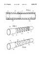
- FIG. 5is a greatly enlarged perspective view of stiffening component for incorporation within a alternative embodiment cannula of the present invention
- FIG. 6,is a greatly enlarged perspective view of an alternative embodiment stiffening component
- FIG. 7is a greatly enlarged, cross-sectional view of the tip component of the cannula of the present invention.
- FIG. 8is a greatly enlarged cross-sectional view of an alternative embodiment tip component
- FIG. 9is a greatly enlarged cross-sectional view of another alternative embodiment tip component.
- FIG. 10is a greatly enlarged, longitudinally compressed, cross-sectional view of an alternative embodiment of the present invention.
- the figuresgenerally illustrate the cannula of the present invention.
- the cannulais most advantageously used as an inflow conduit on the distal end of an implantable intravascular heart pump. In such application it serves to enhance maneuverability through the vasculature and upon placement, accommodates extremely high flow rates with a minimum of adverse effects to the pumped blood.
- the cannulaprovides similar advantages when used as an outflow conduit.
- FIG. 1is a perspective view showing the cannula 12 attached to the distal end of an implantable intravascular blood pump 14.
- Manipulation of a catheter 16 extending from the proximal end of the pumpallows the assembly to be maneuvered through the vasculature to the pumping site such as for example up through the femoral artery, around the aortic arch and with the tip extending into the left ventricle.
- the outer diameter of the cannulamust be limited to about 8 mm while its length must be sufficient to ensure that the pump's discharge port 20 is located clear of the aortic valve even while the tip 18 of the cannula is bottomed out in the left ventricle of a large patient (about 8 cm). Similar dimensions are appropriate for right ventricle applications wherein the distally disposed cannula serves as an outflow conduit.
- the cannula device of the present inventionvery generally consists of a body component 22 of differentiated flexibility and a rigid tip component 24.
- FIG. 2is enlarged, longitudinally compressed, cross-sectional view of the body portion 22 of the cannula 12 of the present invention.
- a rigid pump housing 14is attached at its proximal end while rigid tip 24 is attached thereto at its distal end.
- the componentsare engaged in a stepped 26 fashion and are permanently bonded to one another.
- the body componenthas a constant wall thickness along its entire length and is formed as a layered composite of two materials, one relatively stiff 28, the other relatively more flexible 30.
- a similar effectcan be achieved with the use of two materials of identical chemical composition, albeit with different physical characteristics, such as a polyurethane with different degrees of polymerization.
- the layersare arranged such that the thickness of one material gradually diminishes as the other increases. In the embodiment illustrated in FIG.
- FIG. 2illustrates an embodiment wherein an abrupt change in flexibility is achieved by joining two materials of differentiated flexibility 28b, 30b in a stepped fashion at 31.
- its compositioncomprises substantially 100% of the stiffer material while at the distal end, the composition comprises substantially 100% of the more flexible material.
- the stiffer materialmay consist of any number of materials including but not limited to a polyurethane or resin impregnated fibers while the more flexible material may consist of any number of materials including but not limited to a silicone compound.
- the two different materialsmay in fact comprise the same chemical composition yet be differentiated in terms of for example, degree of polymerization or crystallinity. Two forms of a polyurethane for example, may be combined in accordance with the present invention to yield a flexibility differentiated cannula.
- a spiral spring 29 of for instance, NiTi wireEmbedded within the wall of the body structure.
- the presence of the springimparts significant resistance to radial deformation while the particular alloy employed allows the spring to regain its original shape even after a substantial deformation that it may be subjected to during placement or manipulation of the heart.
- the spring wiremay have any number of cross-sectional shapes including but not limited to round or rectangular cross-sections with the further option of varying axial density in order to change the elasticity or flexibility of the cannula.
- FIG. 6illustrates a further alternative of tubular stiffening component 64 wherein a pattern of rectangular voids 66, varied in terms of size of distribution density imparts the desired differentiation in terms of flexibility.
- the proximal endis solid and thus its stiffness in uncompromised to enable it to serve as a pump housing while the distal end 70 is similarly solid to serve as reinforcement of the tip component to provide for maximal rigidity.
- the tube 60, 64thereby serves to simultaneously provide radial stiffness and a varying degree of resistance to lateral deflection.
- differentiated flexibilityis achieved exclusively via the laser cut metal tube while the polymer makeup of the cannula is unvaried along its length.
- FIGS. 7 and 8illustrates the rigid tip component 24 of the cannula.
- Such componentmay be a separate injection molded part or alternatively, may be of integral construction and incorporates a number of features especially advantageous for high inflow rate applications.
- a number of large elongated openings 34extend along its length, while a central hole 36 at the very distal end is sized to accommodate a guide wire.
- the distal end 38is smooth and rounded without additional openings to prevent injury upon contacting tissue, and/or valve leaflets.
- the interior surface of the tip component directly adjacent the squared off proximal or inflow end 71 of openings 34is formed with an edge contour 40 of generally parabolic cross-section that serves to manage the flow of blood thereabout.
- the shapenot only presents a rounded surface at the point of initial contact with the incoming blood, but additionally serves to smoothly attach the flow of blood to the interior wall with its asymptotic trailing edge contour.
- the risk of excessive shear and cavitationis minimized to thereby minimize the risk of hemolysis while areas of eddying or of low flow rates are substantially eliminated to thereby mitigate the risk of thrombogenisis.
- Similar advantagesmay be achieved by rounding the downstream edges 73 of the openings as shown in FIG. 8. Such configuration provides the advantage of being easily molded.
- FIG. 9illustrates an alternative embodiment especially well suited for outflow applications.
- the distal end of the interior volume of the tip componentis fitted with a generally parabolic protuberance 60 extending proximally along the central axis.
- Such elementdirects flow out through the openings 34a and effectively prevents flow impingement onto a closed distal wall. The resulting reduction in eddying and areas of stagnant flow reduces thrombogenisis.
- the embodimentadditionally illustrates a slanted orientation of the openings 34a as well as their extension well into the rounded distal area 61.
- FIG. 10illustrates an alternative embodiment that incorporates a number of additional features not present in the embodiments shown in the preceding figures.
- the deviceis of integrated construction such that the rigid proximal end of the cannula forms the pump housing 41 while the flexible distal end seamlessly transitions into the rigid tip component 43. No joints or bonds are formed and thus, the seamless transitions from the tip 43 to the cannula 45 and from the cannula 45 to the pump housing 41 effectively obviate any disruption of bloodflow thereover.
- the desired differentiations in stiffnessare achieved by the varied content of epoxy impregnated fibers windings 47 incorporated within the structure. By closely spacing such fibers, and thereby displacing all of a second substantially more flexible material, maximum strength is achieved.
- a layer of biocompatible material 48, 50coats both the internal as well as external surfaces of the device.
- the thickness of the internal layeris increased 51 under the spiral spring 44 so as to preclude migration of such spring into the blood flow.
- the spring wire shown in FIG. 9is of rectangular construction to thereby minimize the wall thickness of the device which is constant along its entire length.
- the proximal end of the springis incorporated well within the fiber windings.
- a sensor 52is incorporated in the wall of the device. In some applications it is desirable to monitor any of a number of parameters at such location for the purpose of gauging the patient's condition and/or the performance of, for example, the associated pump.
- the fabrication of the device illustrated in FIG. 10is achieved by first applying a layer 48 of biocompatible polymer such as polyurethane to a highly polished mandrel 54.
- the thickness of the layeris increased 51 slightly near where the spiral spring 44 is to be subsequently positioned in order to prevent migration of the spring into the fluid path.
- Pre-impregnated carbon fiber filaments 47are then wound about the coated mandrel at an approximate 45° angle to ensure good stability against axial and radial deformation.
- the spacing of successive windingsis controlled such that the fiber content is maximized in those areas where maximum stiffness is desired, i.e., the pump housing and tip component. Such spacing is gradually increased in those areas where gradually more flexibility is desired.
- Areas 55,where maximum flexibility is desiredare totally devoid of fibers.
- the outside surfaceis machined down to its final dimension and the ports are formed in the tip component 43.
- Layers of an elastic polymer 49such as polyurethane or silicone are then applied in order to fill the areas between adjacent fibers and the spring windings.
- a final layer 50 of biocompatible polymeris applied to the exterior of the entire device to render all surfaces biocompatible. After all materials have cured, the finished device is slipped off the mandrel 54.
- the tip component 24is fabricated separately such as by injection molding.
- the tipis then either attached by adhesive or by solvent bonding.
- a final layer of biocompatible polymermay then be applied to the assembly to render its surfaces biocompatible and to fill in any gaps that may be present along the joints between adjacent components.
- a single stiffening componentcomprising the pump housing, cannula and tip are fashioned from a single metal tube having a varying pattern of voids formed therein such as by laser cutting. Since the density of voids at any given point along its length determines the resulting flexibility of the structure at such point, no voids or a minimum of voids are formed in the pump housing and tip sections of the device while a pattern of voids is formed therebetween to impart an increasing degree of flexibility to the cannula's body component. The surfaces of the tube and the voids therebetween are subsequently coated and filled with a polymer in a fashion as described above.
- the cannula of the present inventionattached to the distal end of an implantable intravascular blood pump, is inserted into the femoral artery and maneuvered upwardly toward the heart.
- the devicemay be inserted directly into the aorta via a sternotomy.
- the flexible distal endpermits the device to negotiate the convolutions of the artery including the aortic arch.
- the increased stiffness of the proximal endpermits adequate axial and torsional forces to be transmitted to the tip to enhance control thereof and thereby facilitate proper advancement of the device.
- Blind retrograde insertion through the aortic valveis accomplished by simply advancing the tip until the valve is engaged.
- the tip attempt to enter while the aortic valvewill simply pass into the left ventricle.
- the tip attempt to enter while the aortic valveis closed, it will engage the sinus region behind the leaflet, while further advancement will cause the flexible region near the cannula's distal end to fold over to allow a more proximal and stiffer section of the cannula to breach the valve first.
- the devicecan be pulled back and reinserted. Once inside, the cannula has room to unfold and is ready for service.
- a similar techniqueis used for right side placement.
Landscapes
- Health & Medical Sciences (AREA)
- Heart & Thoracic Surgery (AREA)
- Life Sciences & Earth Sciences (AREA)
- Engineering & Computer Science (AREA)
- General Health & Medical Sciences (AREA)
- Public Health (AREA)
- Biomedical Technology (AREA)
- Veterinary Medicine (AREA)
- Hematology (AREA)
- Animal Behavior & Ethology (AREA)
- Anesthesiology (AREA)
- Cardiology (AREA)
- Biophysics (AREA)
- Pulmonology (AREA)
- Mechanical Engineering (AREA)
- Vascular Medicine (AREA)
- External Artificial Organs (AREA)
- Measurement Of The Respiration, Hearing Ability, Form, And Blood Characteristics Of Living Organisms (AREA)
- Media Introduction/Drainage Providing Device (AREA)
- Materials For Medical Uses (AREA)
Abstract
Description
Claims (42)
Priority Applications (6)
| Application Number | Priority Date | Filing Date | Title |
|---|---|---|---|
| US08/970,135US6007478A (en) | 1997-11-13 | 1997-11-13 | Cannula having constant wall thickness with increasing distal flexibility and method of making |
| DE69826411TDE69826411T2 (en) | 1997-11-13 | 1998-11-11 | Improved cannula device |
| EP98121448AEP0916359B1 (en) | 1997-11-13 | 1998-11-11 | Improved cannula device |
| AT98121448TATE276784T1 (en) | 1997-11-13 | 1998-11-11 | IMPROVED CANNULA DEVICE |
| CA002254006ACA2254006A1 (en) | 1997-11-13 | 1998-11-12 | Improved cannula device |
| JP10361823AJPH11239617A (en) | 1997-11-13 | 1998-11-13 | Improved cannula device |
Applications Claiming Priority (1)
| Application Number | Priority Date | Filing Date | Title |
|---|---|---|---|
| US08/970,135US6007478A (en) | 1997-11-13 | 1997-11-13 | Cannula having constant wall thickness with increasing distal flexibility and method of making |
Publications (1)
| Publication Number | Publication Date |
|---|---|
| US6007478Atrue US6007478A (en) | 1999-12-28 |
Family
ID=25516493
Family Applications (1)
| Application Number | Title | Priority Date | Filing Date |
|---|---|---|---|
| US08/970,135Expired - LifetimeUS6007478A (en) | 1997-11-13 | 1997-11-13 | Cannula having constant wall thickness with increasing distal flexibility and method of making |
Country Status (6)
| Country | Link |
|---|---|
| US (1) | US6007478A (en) |
| EP (1) | EP0916359B1 (en) |
| JP (1) | JPH11239617A (en) |
| AT (1) | ATE276784T1 (en) |
| CA (1) | CA2254006A1 (en) |
| DE (1) | DE69826411T2 (en) |
Cited By (147)
| Publication number | Priority date | Publication date | Assignee | Title |
|---|---|---|---|---|
| US6173199B1 (en)* | 1998-05-05 | 2001-01-09 | Syncro Medical Innovations, Inc. | Method and apparatus for intubation of a patient |
| WO2001007231A1 (en)* | 1999-07-23 | 2001-02-01 | Tfx Medical Extrusion Products | Introducer device having variable flexibility and kink resistance and method of manufacture of same |
| US6500130B2 (en) | 2000-12-21 | 2002-12-31 | Scimed Life Systems, Inc. | Steerable guidewire |
| US20030069522A1 (en)* | 1995-12-07 | 2003-04-10 | Jacobsen Stephen J. | Slotted medical device |
| US6585719B2 (en) | 2001-01-04 | 2003-07-01 | Scimed Life Systems, Inc. | Low profile metal/polymer tubes |
| US20030135198A1 (en)* | 1999-07-23 | 2003-07-17 | Tfx Medical Extrusion Products | Catheter device having multi-lumen reinforced shaft and method of manufacture for same |
| US6620202B2 (en) | 2001-10-16 | 2003-09-16 | Scimed Life Systems, Inc. | Medical stent with variable coil and related methods |
| US20030236506A1 (en)* | 2002-06-20 | 2003-12-25 | Eric Schofield | Dual outside diameter cannula for insertion into bone |
| US6685679B2 (en)* | 2000-12-06 | 2004-02-03 | Scimed Life Systems, Inc. | Interlocking metal shaft |
| US6719804B2 (en) | 2001-04-02 | 2004-04-13 | Scimed Life Systems, Inc. | Medical stent and related methods |
| US6802806B2 (en) | 2002-09-23 | 2004-10-12 | Cleveland Clinic Foundation | Apparatus for use with an inflow cannula of ventricular assist device |
| US6994666B2 (en)* | 2001-06-05 | 2006-02-07 | Edwards Lifesciences Corporation | Non-porous smooth ventricular assist device conduit |
| US20060074271A1 (en)* | 2004-07-22 | 2006-04-06 | Cotter Christopher J | Heart pump connector |
| US20060253059A1 (en)* | 2005-04-21 | 2006-11-09 | Edwards Lifesciences, Llc | Soft-flow aortic cannula tip |
| US20060258987A1 (en)* | 2005-05-10 | 2006-11-16 | Cook Incorporated | Catheter stiffening member |
| US20070049787A1 (en)* | 2002-09-10 | 2007-03-01 | Miwatec Co., Ltd. | Cannula tip for a cardiac assist device |
| US20070073310A1 (en)* | 2005-09-29 | 2007-03-29 | Cook Incorporated | Method for joining medical devices |
| US20070225784A1 (en)* | 2006-03-23 | 2007-09-27 | Cardiac Pacemakers, Inc. | Medical lead having a variable change in stiffness |
| US20080058767A1 (en)* | 2006-09-06 | 2008-03-06 | Rotman Carlos A | Tubal cannulator and methods of use |
| US20080097592A1 (en)* | 2005-02-14 | 2008-04-24 | Vascutek Limited | Artificial Blood Vessel |
| US20080132747A1 (en)* | 2006-12-01 | 2008-06-05 | Medical Value Partners, Llc | Medical Device |
| US20080140022A1 (en)* | 2006-12-08 | 2008-06-12 | Warsaw Orthopedic, Inc. | Coated Cannula with Protective Tip for Insertion Into a Patient |
| US20080194991A1 (en)* | 2007-02-09 | 2008-08-14 | Teague James A | Extruded guidewires and methods of making |
| US20080281230A1 (en)* | 2007-05-11 | 2008-11-13 | Terumo Kabushiki Kaisha | Guide Wire |
| US20080306327A1 (en)* | 2007-06-05 | 2008-12-11 | Medical Value Partners, Llc | Apparatus Comprising a Drive Cable for a Medical Device |
| US20090062597A1 (en)* | 2007-08-29 | 2009-03-05 | Medical Value Partners, Llc | Article Comprising an Impeller |
| US20090076482A1 (en)* | 2007-09-14 | 2009-03-19 | Avalon Laboratories, Inc. | Cannula reinforcing band and method |
| US20100022939A1 (en)* | 2008-07-16 | 2010-01-28 | Heinrich Schima | Cannula tip for use with a vad |
| US20100210895A1 (en)* | 1999-09-03 | 2010-08-19 | Aboul-Hosn Walid N | Guidable Intravascular Blood Pump and Related Methods |
| US20110009687A1 (en)* | 2007-02-27 | 2011-01-13 | Miracor Medical Systems Gmbh | Catheter to assist the performance of a heart |
| US20110137186A1 (en)* | 2008-08-06 | 2011-06-09 | Carag Ag | Device for measuring the blood flow of a body tissue |
| US20110152721A1 (en)* | 2008-01-23 | 2011-06-23 | Ran Sela | Sensor mounted flexible guidewire |
| US7976271B2 (en) | 2006-01-13 | 2011-07-12 | Heartware, Inc. | Stabilizing drive for contactless rotary blood pump impeller |
| US7993260B2 (en) | 1997-10-09 | 2011-08-09 | Thoratec Corporation | Implantable heart assist system and method of applying same |
| US8137293B2 (en) | 2009-11-17 | 2012-03-20 | Boston Scientific Scimed, Inc. | Guidewires including a porous nickel-titanium alloy |
| US8376707B2 (en) | 2004-09-17 | 2013-02-19 | Thoratec Corporation | Expandable impeller pump |
| US20130102892A1 (en)* | 2008-01-23 | 2013-04-25 | St. Jude Medical, Atrial Fibrillation Division, Inc. | Sensor mounted flexible guidewire |
| US8449443B2 (en) | 2008-10-06 | 2013-05-28 | Indiana University Research And Technology Corporation | Active or passive assistance in the circulatory system |
| US8485961B2 (en) | 2011-01-05 | 2013-07-16 | Thoratec Corporation | Impeller housing for percutaneous heart pump |
| US8535243B2 (en) | 2008-09-10 | 2013-09-17 | Boston Scientific Scimed, Inc. | Medical devices and tapered tubular members for use in medical devices |
| US8535211B2 (en) | 2009-07-01 | 2013-09-17 | Thoratec Corporation | Blood pump with expandable cannula |
| US20130253328A1 (en)* | 2012-03-23 | 2013-09-26 | Acist Medical Systems, Inc. | Catheter sheath and methods thereof |
| US8551021B2 (en) | 2010-03-31 | 2013-10-08 | Boston Scientific Scimed, Inc. | Guidewire with an improved flexural rigidity profile |
| DE102013008168A1 (en) | 2012-05-14 | 2013-11-14 | Thoratec Corporation | Impeller for catheter pump |
| DE102013008159A1 (en) | 2012-05-14 | 2013-11-14 | Thoratec Corporation | Sheath system for catheter pump |
| DE102013008158A1 (en) | 2012-05-14 | 2013-11-14 | Thoratec Corporation | Distal bearing carrier |
| WO2013173245A1 (en) | 2012-05-14 | 2013-11-21 | Thoratec Corporation | Impeller for catheter pump |
| WO2013173240A1 (en) | 2012-05-14 | 2013-11-21 | Thoratec Corporation | Sheath system for catheter pump |
| WO2013173239A1 (en) | 2012-05-14 | 2013-11-21 | Thoratec Corporation | Distal bearing support |
| US8591393B2 (en) | 2011-01-06 | 2013-11-26 | Thoratec Corporation | Catheter pump |
| US8597170B2 (en) | 2011-01-05 | 2013-12-03 | Thoratec Corporation | Catheter pump |
| DE102013011042A1 (en) | 2012-07-03 | 2014-01-09 | Thoratec Corporation | Motor assembly for catheter pump |
| WO2014008105A1 (en) | 2012-07-03 | 2014-01-09 | Thoratec Corporation | Catheter pump |
| WO2014008102A1 (en) | 2012-07-03 | 2014-01-09 | Thoratec Corporation | Motor assembly for catheter pump |
| US20140025045A1 (en)* | 2012-07-17 | 2014-01-23 | Niels A. Abt | Soft tip cannula |
| US8672611B2 (en) | 2006-01-13 | 2014-03-18 | Heartware, Inc. | Stabilizing drive for contactless rotary blood pump impeller |
| US8795254B2 (en) | 2008-12-10 | 2014-08-05 | Boston Scientific Scimed, Inc. | Medical devices with a slotted tubular member having improved stress distribution |
| US8795202B2 (en) | 2011-02-04 | 2014-08-05 | Boston Scientific Scimed, Inc. | Guidewires and methods for making and using the same |
| US20140257111A1 (en)* | 2011-11-25 | 2014-09-11 | Terumo Kabushiki Kaisha | Medical tube and catheter |
| WO2014143593A1 (en) | 2013-03-15 | 2014-09-18 | Thoratec Corporation | Catheter pump assembly including a stator |
| WO2014164136A1 (en) | 2013-03-13 | 2014-10-09 | Thoratec Corporation | Fluid handling system |
| US20150065953A1 (en)* | 2013-08-30 | 2015-03-05 | Strategic Polymer Sciences, Inc. | Catheter having a steerable tip |
| US9072874B2 (en) | 2011-05-13 | 2015-07-07 | Boston Scientific Scimed, Inc. | Medical devices with a heat transfer region and a heat sink region and methods for manufacturing medical devices |
| US9138518B2 (en) | 2011-01-06 | 2015-09-22 | Thoratec Corporation | Percutaneous heart pump |
| US9308302B2 (en) | 2013-03-15 | 2016-04-12 | Thoratec Corporation | Catheter pump assembly including a stator |
| US9327067B2 (en) | 2012-05-14 | 2016-05-03 | Thoratec Corporation | Impeller for catheter pump |
| US9339597B2 (en) | 2012-02-07 | 2016-05-17 | Hridaya Inc. | Hemodynamic assist device |
| US9364592B2 (en) | 2004-09-17 | 2016-06-14 | The Penn State Research Foundation | Heart assist device with expandable impeller pump |
| US9521990B2 (en) | 2011-05-11 | 2016-12-20 | Acist Medical Systems, Inc. | Variable-stiffness imaging window and production method thereof |
| US9597480B2 (en) | 2009-10-07 | 2017-03-21 | Endophys Holding, LLC | Intraluminal devices and systems |
| WO2017048733A1 (en) | 2015-09-14 | 2017-03-23 | Thoratec Corporation | Fluid handling system |
| US9603983B2 (en) | 2009-10-23 | 2017-03-28 | Ecp Entwicklungsgesellschaft Mbh | Catheter pump arrangement and flexible shaft arrangement having a core |
| US9675738B2 (en) | 2015-01-22 | 2017-06-13 | Tc1 Llc | Attachment mechanisms for motor of catheter pump |
| US9675739B2 (en) | 2015-01-22 | 2017-06-13 | Tc1 Llc | Motor assembly with heat exchanger for catheter pump |
| US20170215918A1 (en)* | 2016-01-29 | 2017-08-03 | Abiomed, Inc. | Thermoform cannula with variable cannula body stiffness |
| EP3205360A1 (en)* | 2016-02-11 | 2017-08-16 | Abiomed Europe GmbH | Blood pump |
| US9770543B2 (en) | 2015-01-22 | 2017-09-26 | Tc1 Llc | Reduced rotational mass motor assembly for catheter pump |
| US9821146B2 (en) | 2015-09-22 | 2017-11-21 | Abiomed, Inc. | Guidewire for cannula placement |
| US9827356B2 (en) | 2014-04-15 | 2017-11-28 | Tc1 Llc | Catheter pump with access ports |
| US9907890B2 (en) | 2015-04-16 | 2018-03-06 | Tc1 Llc | Catheter pump with positioning brace |
| WO2018089970A1 (en) | 2016-11-14 | 2018-05-17 | Tc1 Llc | Sheath assembly for catheter pump |
| US10029037B2 (en) | 2014-04-15 | 2018-07-24 | Tc1 Llc | Sensors for catheter pumps |
| US10105475B2 (en) | 2014-04-15 | 2018-10-23 | Tc1 Llc | Catheter pump introducer systems and methods |
| CN109068941A (en)* | 2016-04-22 | 2018-12-21 | 奥林巴斯株式会社 | Flexible pipe insertion apparatus |
| US10315013B2 (en) | 2001-07-13 | 2019-06-11 | Endophys Holdings, Llc | Sheath with sensing capabilities |
| CN110251806A (en)* | 2012-12-21 | 2019-09-20 | Ecp发展有限责任公司 | Sheath assembly for inserting cord-like elements, especially catheters, into a patient |
| US10420456B2 (en) | 2007-12-20 | 2019-09-24 | Acist Medical Systems, Inc. | Imaging probe housing with fluid flushing |
| US10449279B2 (en) | 2014-08-18 | 2019-10-22 | Tc1 Llc | Guide features for percutaneous catheter pump |
| WO2019229210A1 (en)* | 2018-05-30 | 2019-12-05 | Kardion Gmbh | Line device for conducting a blood flow for a heart support system, and production and assembly method |
| CN110624145A (en)* | 2018-12-29 | 2019-12-31 | 北京工业大学 | An artificial heart inlet connector to prevent intraventricular thrombosis |
| WO2020009789A1 (en) | 2018-07-05 | 2020-01-09 | Fresenius Medical Care Holdings, Inc. | Flexible container systems and nozzles, and related methods |
| WO2020016438A1 (en)* | 2018-07-20 | 2020-01-23 | Kardion Gmbh | Feed line for a pump unit of a cardiac assistance system, cardiac assistance system and method for producing a feed line for a pump unit of a cardiac assistance system |
| CN110785191A (en)* | 2017-06-21 | 2020-02-11 | 阿比奥梅德欧洲股份有限公司 | Cannula for intravascular blood pump |
| US10569048B2 (en) | 2016-08-23 | 2020-02-25 | Asahi Intecc Co., Ltd. | Junction structure and catheter having the junction structure |
| US10583232B2 (en) | 2014-04-15 | 2020-03-10 | Tc1 Llc | Catheter pump with off-set motor position |
| WO2020112265A1 (en)* | 2018-11-29 | 2020-06-04 | Heartware, Inc. | Thrombus clearing manifold for ventricular assist devices |
| US10881770B2 (en) | 2018-01-10 | 2021-01-05 | Magenta Medical Ltd. | Impeller for blood pump |
| US10918826B2 (en) | 2007-06-26 | 2021-02-16 | Nordson Corporation | Coaxial venal cannula |
| US11033728B2 (en) | 2013-03-13 | 2021-06-15 | Tc1 Llc | Fluid handling system |
| US20210187272A1 (en)* | 2013-03-13 | 2021-06-24 | Tc1 Llc | Sheath assembly for catheter pump |
| USRE48649E1 (en)* | 2012-04-27 | 2021-07-20 | Abiomed Europe Gmbh | Intravascular rotary blood pump |
| US11160970B2 (en) | 2016-07-21 | 2021-11-02 | Tc1 Llc | Fluid seals for catheter pump motor assembly |
| US11167121B2 (en)* | 2018-05-15 | 2021-11-09 | Cardiovascular Systems, Inc. | Intravascular pump with integrated isolated conductor(s) and methods thereof |
| US11191944B2 (en) | 2019-01-24 | 2021-12-07 | Magenta Medical Ltd. | Distal tip element for a ventricular assist device |
| US11235138B2 (en) | 2015-09-25 | 2022-02-01 | Procyrion, Inc. | Non-occluding intravascular blood pump providing reduced hemolysis |
| US11241569B2 (en) | 2004-08-13 | 2022-02-08 | Procyrion, Inc. | Method and apparatus for long-term assisting a left ventricle to pump blood |
| US11260212B2 (en) | 2016-10-25 | 2022-03-01 | Magenta Medical Ltd. | Ventricular assist device |
| US11291826B2 (en) | 2018-01-10 | 2022-04-05 | Magenta Medical Ltd. | Axially-elongatable frame and impeller |
| US11305105B2 (en) | 2014-05-13 | 2022-04-19 | Abiomed, Inc. | Cannula assembly |
| US11324940B2 (en) | 2019-12-03 | 2022-05-10 | Procyrion, Inc. | Blood pumps |
| US11351359B2 (en) | 2019-12-13 | 2022-06-07 | Procyrion, Inc. | Support structures for intravascular blood pumps |
| US11368081B2 (en) | 2018-01-24 | 2022-06-21 | Kardion Gmbh | Magnetic coupling element with a magnetic bearing function |
| US11389638B2 (en)* | 2012-02-07 | 2022-07-19 | Hridaya, Inc. | Hemodynamic assist device |
| CN115154892A (en)* | 2022-06-15 | 2022-10-11 | 苏州心擎医疗技术有限公司 | Ventricular assist device |
| US11491322B2 (en) | 2016-07-21 | 2022-11-08 | Tc1 Llc | Gas-filled chamber for catheter pump motor assembly |
| US11666309B2 (en) | 2013-12-19 | 2023-06-06 | Acist Medical Systems, Inc. | Catheter sheath system and method |
| WO2023141250A1 (en)* | 2022-01-20 | 2023-07-27 | Boston Scientific Scimed Inc. | Percutaneous circulatory support device including guidewire distal tip portion |
| US11754075B2 (en) | 2018-07-10 | 2023-09-12 | Kardion Gmbh | Impeller for an implantable, vascular support system |
| US20240075248A1 (en)* | 2022-09-01 | 2024-03-07 | Becton, Dickinson And Company | Instrument Delivery Device with Nested Housing |
| US11944805B2 (en) | 2020-01-31 | 2024-04-02 | Kardion Gmbh | Pump for delivering a fluid and method of manufacturing a pump |
| US12004848B2 (en) | 2018-11-02 | 2024-06-11 | Boston Scientific Medical Device Limited | Blood flow meter |
| US12005248B2 (en) | 2018-05-16 | 2024-06-11 | Kardion Gmbh | Rotor bearing system |
| US12064615B2 (en) | 2018-05-30 | 2024-08-20 | Kardion Gmbh | Axial-flow pump for a ventricular assist device and method for producing an axial-flow pump for a ventricular assist device |
| US12076514B2 (en) | 2019-12-24 | 2024-09-03 | Angiomed Gmbh & Co. Medizintechnik Kg | Puncture device to be used in creating a TIPS shunt |
| US12107474B2 (en) | 2018-05-16 | 2024-10-01 | Kardion Gmbh | End-face rotating joint for transmitting torques |
| EP4225423A4 (en)* | 2020-10-08 | 2024-10-09 | Shifamed Holdings, LLC | INTRAVASCULAR BLOOD PUMPS AND METHODS OF USE |
| US12128227B2 (en) | 2020-04-07 | 2024-10-29 | Magenta Medical Ltd. | Manufacture of an impeller |
| CN118846366A (en)* | 2024-07-08 | 2024-10-29 | 深圳核心医疗科技股份有限公司 | Cannula assembly and blood pump |
| US12144976B2 (en) | 2018-06-21 | 2024-11-19 | Kardion Gmbh | Method and device for detecting a wear condition of a ventricular assist device and for operating same, and ventricular assist device |
| US12171994B2 (en) | 2019-09-11 | 2024-12-24 | Boston Scientific Scimed, Inc. | Reduced thrombosis blood pump with washout bearing |
| US12178554B2 (en) | 2018-06-06 | 2024-12-31 | Kardion Gmbh | Systems and methods for determining a viscosity of a fluid |
| US12194287B2 (en) | 2018-05-30 | 2025-01-14 | Kardion Gmbh | Method of manufacturing electrical conductor tracks in a region of an intravascular blood pump |
| US12201821B2 (en) | 2018-06-06 | 2025-01-21 | Kardion Gmbh | Method for determining a flow rate of a fluid flowing through an implanted vascular support system, and implantable vascular support system |
| US12201823B2 (en) | 2018-05-30 | 2025-01-21 | Kardion Gmbh | Line device for conducting a blood flow for a heart support system, heart support system, and method for producing a line device |
| EP4084856B1 (en)* | 2019-12-31 | 2025-01-29 | Abiomed, Inc. | Blood pump distal outflow cage |
| US12222267B2 (en) | 2018-06-06 | 2025-02-11 | Kardion Gmbh | Analysis device and method for analyzing a viscosity of a fluid |
| US12257424B2 (en) | 2018-06-06 | 2025-03-25 | Kardion Gmbh | Implantable ventricular assist system and method for operating same |
| US12263333B2 (en) | 2018-06-21 | 2025-04-01 | Kardion Gmbh | Stator vane device for guiding the flow of a fluid flowing out of an outlet opening of a ventricular assist device, ventricular assist device with stator vane device, method for operating a stator vane device and manufacturing method |
| US12310708B2 (en) | 2018-06-06 | 2025-05-27 | Kardion Gmbh | Systems and methods for determining a flow speed of a fluid flowing through a cardiac assist device |
| US12311160B2 (en) | 2018-06-06 | 2025-05-27 | Kardion Gmbh | Method and system for determining the speed of sound in a fluid in the region of a cardiac support system |
| US12324906B2 (en) | 2018-06-06 | 2025-06-10 | Kardion Gmbh | Systems and methods for determining a total blood volume flow in a cardiac support system and vascular support system |
| US12370358B2 (en) | 2018-02-01 | 2025-07-29 | Shifamed Holdings, Llc | Intravascular blood pumps and methods of use and manufacture |
| US12377256B2 (en) | 2018-06-06 | 2025-08-05 | Kardion Gmbh | Cardiac support system flow measurement using pressure sensors |
| US12383727B2 (en) | 2018-05-30 | 2025-08-12 | Kardion Gmbh | Motor housing module for a heart support system, and heart support system and method for mounting a heart support system |
| US12390633B2 (en) | 2018-08-07 | 2025-08-19 | Kardion Gmbh | Bearing device for a heart support system, and method for rinsing a space in a bearing device for a heart support system |
| US12409310B2 (en) | 2019-12-11 | 2025-09-09 | Shifamed Holdings, Llc | Descending aorta and vena cava blood pumps |
| US12440663B2 (en) | 2022-04-18 | 2025-10-14 | Magenta Medical Ltd. | Curved tube for a ventricular assist device |
Families Citing this family (75)
| Publication number | Priority date | Publication date | Assignee | Title |
|---|---|---|---|---|
| AU7354400A (en)* | 1999-09-03 | 2001-04-10 | A-Med Systems, Inc. | Guidable intravascular blood pump and related methods |
| JP2001161805A (en)* | 1999-12-10 | 2001-06-19 | Hideo Takehara | Indwelling l-shaped catheter |
| DE10059714C1 (en)* | 2000-12-01 | 2002-05-08 | Impella Cardiotech Ag | Intravasal pump has pump stage fitted with flexible expandible sleeve contricted during insertion through blood vessel |
| DE50209306D1 (en) | 2002-12-31 | 2007-03-08 | Abbott Lab Vascular Entpr Ltd | Catheter with a more flexible area between stem and tip, and method of making the same |
| DE20304533U1 (en)* | 2003-03-21 | 2004-08-05 | Impella Cardiosystems Ag | An insertion device for inserting an object into a body vessel |
| DE10336902C5 (en) | 2003-08-08 | 2019-04-25 | Abiomed Europe Gmbh | Intracardiac pumping device |
| US7794448B2 (en) | 2004-05-27 | 2010-09-14 | Abbott Laboratories | Multiple lumen catheter and method of making same |
| US7625353B2 (en) | 2004-05-27 | 2009-12-01 | Abbott Laboratories | Catheter having first and second guidewire tubes and overlapping stiffening members |
| US7527606B2 (en)* | 2004-05-27 | 2009-05-05 | Abbott Laboratories | Catheter having main body portion with coil-defined guidewire passage |
| US7628769B2 (en) | 2004-05-27 | 2009-12-08 | Abbott Laboratories | Catheter having overlapping stiffening members |
| US7785318B2 (en) | 2004-05-27 | 2010-08-31 | Abbott Laboratories | Catheter having plurality of stiffening members |
| US7815627B2 (en) | 2004-05-27 | 2010-10-19 | Abbott Laboratories | Catheter having plurality of stiffening members |
| US7658723B2 (en) | 2004-05-27 | 2010-02-09 | Abbott Laboratories | Catheter having plurality of stiffening members |
| US7785439B2 (en) | 2004-09-29 | 2010-08-31 | Abbott Laboratories Vascular Enterprises Limited | Method for connecting a catheter balloon with a catheter shaft of a balloon catheter |
| US20070233040A1 (en)* | 2006-03-31 | 2007-10-04 | Boston Scientific Scimed, Inc. | Flexible endoscope with variable stiffness shaft |
| US7993303B2 (en) | 2006-04-21 | 2011-08-09 | Abbott Laboratories | Stiffening support catheter and methods for using the same |
| US8246574B2 (en)* | 2006-04-21 | 2012-08-21 | Abbott Laboratories | Support catheter |
| US7927305B2 (en) | 2006-04-21 | 2011-04-19 | Abbott Laboratories | Systems, methods, and devices for injecting media contrast |
| US8206370B2 (en) | 2006-04-21 | 2012-06-26 | Abbott Laboratories | Dual lumen guidewire support catheter |
| US7890174B2 (en)* | 2006-06-02 | 2011-02-15 | Cardiac Pacemakers, Inc. | Medical electrical lead with deployable fixation features |
| EP2476384B1 (en) | 2006-11-22 | 2015-11-04 | Applied Medical Resources Corporation | Trocar cannula with atraumatic tip |
| US8439859B2 (en) | 2007-10-08 | 2013-05-14 | Ais Gmbh Aachen Innovative Solutions | Catheter device |
| US8489190B2 (en) | 2007-10-08 | 2013-07-16 | Ais Gmbh Aachen Innovative Solutions | Catheter device |
| EP2915476B1 (en) | 2008-03-10 | 2017-04-05 | Fortimedix Surgical B.V. | Instrument for endoscopic applications |
| WO2009127236A1 (en) | 2008-04-18 | 2009-10-22 | Fortimedix B.V. | An instrument for endoscopic applications or the like |
| EP2194278A1 (en) | 2008-12-05 | 2010-06-09 | ECP Entwicklungsgesellschaft mbH | Fluid pump with a rotor |
| EP2216059A1 (en) | 2009-02-04 | 2010-08-11 | ECP Entwicklungsgesellschaft mbH | Catheter device with a catheter and an actuation device |
| EP2229965A1 (en) | 2009-03-18 | 2010-09-22 | ECP Entwicklungsgesellschaft mbH | Fluid pump with particular form of a rotor blade |
| EP2246078A1 (en) | 2009-04-29 | 2010-11-03 | ECP Entwicklungsgesellschaft mbH | Shaft assembly with a shaft which moves within a fluid-filled casing |
| EP2248544A1 (en) | 2009-05-05 | 2010-11-10 | ECP Entwicklungsgesellschaft mbH | Fluid pump with variable circumference, particularly for medical use |
| EP2266640A1 (en) | 2009-06-25 | 2010-12-29 | ECP Entwicklungsgesellschaft mbH | Compressible and expandable turbine blade for a fluid pump |
| EP2282070B1 (en) | 2009-08-06 | 2012-10-17 | ECP Entwicklungsgesellschaft mbH | Catheter device with a coupling device for a drive device |
| EP2299119B1 (en) | 2009-09-22 | 2018-11-07 | ECP Entwicklungsgesellschaft mbH | Inflatable rotor for a fluid pump |
| EP2298371A1 (en) | 2009-09-22 | 2011-03-23 | ECP Entwicklungsgesellschaft mbH | Function element, in particular fluid pump with a housing and a transport element |
| EP2298372A1 (en) | 2009-09-22 | 2011-03-23 | ECP Entwicklungsgesellschaft mbH | Rotor for an axial pump for transporting a fluid |
| EP2314330A1 (en) | 2009-10-23 | 2011-04-27 | ECP Entwicklungsgesellschaft mbH | Flexible shaft arrangement |
| EP2338540A1 (en) | 2009-12-23 | 2011-06-29 | ECP Entwicklungsgesellschaft mbH | Delivery blade for a compressible rotor |
| EP2338541A1 (en) | 2009-12-23 | 2011-06-29 | ECP Entwicklungsgesellschaft mbH | Radial compressible and expandable rotor for a fluid pump |
| EP2338539A1 (en) | 2009-12-23 | 2011-06-29 | ECP Entwicklungsgesellschaft mbH | Pump device with a detection device |
| EP2347778A1 (en) | 2010-01-25 | 2011-07-27 | ECP Entwicklungsgesellschaft mbH | Fluid pump with a radially compressible rotor |
| CA2787632C (en)* | 2010-02-11 | 2017-05-16 | Circulite, Inc. | Cannula lined with tissue in-growth material and method of using the same |
| KR101845213B1 (en) | 2010-02-17 | 2018-05-18 | 플로우 포워드 메디컬, 인크. | System and method to increase the overall diameter of veins |
| EP2363157A1 (en) | 2010-03-05 | 2011-09-07 | ECP Entwicklungsgesellschaft mbH | Device for exerting mechanical force on a medium, in particular fluid pump |
| EP2388029A1 (en) | 2010-05-17 | 2011-11-23 | ECP Entwicklungsgesellschaft mbH | Pump array |
| WO2011150116A1 (en)* | 2010-05-26 | 2011-12-01 | Corbett Scott C | Anatomic fit of a percutaneous vad for right heart support |
| EP2399639A1 (en) | 2010-06-25 | 2011-12-28 | ECP Entwicklungsgesellschaft mbH | System for introducing a pump |
| EP2407187A3 (en) | 2010-07-15 | 2012-06-20 | ECP Entwicklungsgesellschaft mbH | Blood pump for invasive application within the body of a patient |
| EP2407186A1 (en) | 2010-07-15 | 2012-01-18 | ECP Entwicklungsgesellschaft mbH | Rotor for a pump, produced with an initial elastic material |
| EP2407185A1 (en) | 2010-07-15 | 2012-01-18 | ECP Entwicklungsgesellschaft mbH | Radial compressible and expandable rotor for a pump with a turbine blade |
| EP2422735A1 (en) | 2010-08-27 | 2012-02-29 | ECP Entwicklungsgesellschaft mbH | Implantable blood transportation device, manipulation device and coupling device |
| EP2497521A1 (en) | 2011-03-10 | 2012-09-12 | ECP Entwicklungsgesellschaft mbH | Push device for axial insertion of a string-shaped, flexible body |
| KR102062132B1 (en) | 2011-08-17 | 2020-01-03 | 플로우 포워드 메디컬, 인크. | Blood pump systems and methods |
| EP2564771A1 (en) | 2011-09-05 | 2013-03-06 | ECP Entwicklungsgesellschaft mbH | Medicinal product with a functional element for invasive use in the body of a patient |
| US8926492B2 (en) | 2011-10-11 | 2015-01-06 | Ecp Entwicklungsgesellschaft Mbh | Housing for a functional element |
| EP2606919A1 (en) | 2011-12-22 | 2013-06-26 | ECP Entwicklungsgesellschaft mbH | Sluice device for inserting a catheter |
| EP2606920A1 (en) | 2011-12-22 | 2013-06-26 | ECP Entwicklungsgesellschaft mbH | Sluice device for inserting a catheter |
| US10258730B2 (en) | 2012-08-17 | 2019-04-16 | Flow Forward Medical, Inc. | Blood pump systems and methods |
| AU2017257508B2 (en)* | 2016-04-29 | 2021-10-14 | Artio Medical, Inc. | Conduit tips and systems and methods for use |
| US10722625B2 (en) | 2016-05-17 | 2020-07-28 | Abiomed, Inc. | Corkscrew shape for right-sided cardiac device |
| EP3506960B1 (en) | 2016-09-01 | 2025-04-23 | Abiomed, Inc. | Anti-suction blood pump inlet |
| CN109789292B (en) | 2016-10-05 | 2022-11-01 | 祥丰医疗私人有限公司 | Modular vascular catheter |
| CA3066361A1 (en) | 2017-06-07 | 2018-12-13 | Shifamed Holdings, Llc | Intravascular fluid movement devices, systems, and methods of use |
| WO2019094963A1 (en) | 2017-11-13 | 2019-05-16 | Shifamed Holdings, Llc | Intravascular fluid movement devices, systems, and methods of use |
| DE102018208892A1 (en)* | 2018-06-06 | 2019-12-12 | Kardion Gmbh | A sensor head device for a minimally invasive cardiac assist system and method of manufacturing a sensor head device for a cardiac assist system |
| US12161857B2 (en) | 2018-07-31 | 2024-12-10 | Shifamed Holdings, Llc | Intravascular blood pumps and methods of use |
| WO2020073047A1 (en) | 2018-10-05 | 2020-04-09 | Shifamed Holdings, Llc | Intravascular blood pumps and methods of use |
| WO2021011473A1 (en) | 2019-07-12 | 2021-01-21 | Shifamed Holdings, Llc | Intravascular blood pumps and methods of manufacture and use |
| US11654275B2 (en) | 2019-07-22 | 2023-05-23 | Shifamed Holdings, Llc | Intravascular blood pumps with struts and methods of use and manufacture |
| WO2021062265A1 (en) | 2019-09-25 | 2021-04-01 | Shifamed Holdings, Llc | Intravascular blood pump systems and methods of use and control thereof |
| EP4501393A3 (en) | 2019-09-25 | 2025-04-09 | Shifamed Holdings, LLC | Catheter blood pumps and collapsible pump housings |
| US12121713B2 (en) | 2019-09-25 | 2024-10-22 | Shifamed Holdings, Llc | Catheter blood pumps and collapsible blood conduits |
| CN116367798A (en)* | 2020-11-04 | 2023-06-30 | 爱德华兹生命科学公司 | Catheters for implants and medical procedures and methods of use thereof |
| CN113244527B (en)* | 2021-05-25 | 2024-11-22 | 深圳核心医疗科技股份有限公司 | Cannula assembly, blood pump and method for preparing the cannula assembly |
| AU2022301194A1 (en)* | 2021-07-01 | 2024-01-25 | Abiomed, Inc. | Heart pump assembly with a blood inlet configured to increase blood flow |
| WO2023278599A1 (en)* | 2021-07-02 | 2023-01-05 | Kardion Gmbh | Cardiac assist system with flow guiding nozzle |
Citations (12)
| Publication number | Priority date | Publication date | Assignee | Title |
|---|---|---|---|---|
| US5061256A (en)* | 1987-12-07 | 1991-10-29 | Johnson & Johnson | Inflow cannula for intravascular blood pumps |
| US5112349A (en)* | 1988-09-27 | 1992-05-12 | American Biomed, Inc. | Heart assist pump |
| US5221270A (en)* | 1991-06-28 | 1993-06-22 | Cook Incorporated | Soft tip guiding catheter |
| US5376114A (en)* | 1992-10-30 | 1994-12-27 | Jarvik; Robert | Cannula pumps for temporary cardiac support and methods of their application and use |
| US5533985A (en)* | 1994-04-20 | 1996-07-09 | Wang; James C. | Tubing |
| US5701905A (en)* | 1995-11-13 | 1997-12-30 | Localmed, Inc. | Guide catheter with sensing element |
| US5704926A (en)* | 1994-11-23 | 1998-01-06 | Navarre Biomedical, Ltd. | Flexible catheter |
| US5725513A (en)* | 1994-05-18 | 1998-03-10 | Schneider (Usa) Inc | Thin wall catheter with reinforcing sleeve |
| US5769828A (en)* | 1996-06-13 | 1998-06-23 | Medtronic, Inc. | Two-stage venous cannula with expandable reinforcing member |
| US5792124A (en)* | 1995-01-04 | 1998-08-11 | Medtronic, Inc. | Reinforced catheter which gets softer towards the distal tip |
| US5827242A (en)* | 1996-06-21 | 1998-10-27 | Medtronic, Inc. | Reinforced catheter body and method for its fabrication |
| US5911685A (en)* | 1996-04-03 | 1999-06-15 | Guidant Corporation | Method and apparatus for cardiac blood flow assistance |
Family Cites Families (5)
| Publication number | Priority date | Publication date | Assignee | Title |
|---|---|---|---|---|
| US4301797A (en)* | 1977-05-12 | 1981-11-24 | Pollack Charles N | Balloon-tipped extracorporeal cannula apparatus and method for insertion of same |
| JP2830440B2 (en)* | 1990-09-21 | 1998-12-02 | 東洋紡績株式会社 | Cannula |
| US5085649A (en)* | 1990-11-21 | 1992-02-04 | Flynn Vincent J | Torque controlled tubing |
| DE69432379T2 (en)* | 1993-01-26 | 2004-02-05 | Terumo K.K. | Vascular dilatation device and catheter |
| US5863366A (en)* | 1995-06-07 | 1999-01-26 | Heartport, Inc. | Method of manufacture of a cannula for a medical device |
- 1997
- 1997-11-13USUS08/970,135patent/US6007478A/ennot_activeExpired - Lifetime
- 1998
- 1998-11-11DEDE69826411Tpatent/DE69826411T2/ennot_activeExpired - Lifetime
- 1998-11-11EPEP98121448Apatent/EP0916359B1/ennot_activeExpired - Lifetime
- 1998-11-11ATAT98121448Tpatent/ATE276784T1/ennot_activeIP Right Cessation
- 1998-11-12CACA002254006Apatent/CA2254006A1/ennot_activeAbandoned
- 1998-11-13JPJP10361823Apatent/JPH11239617A/enactivePending
Patent Citations (12)
| Publication number | Priority date | Publication date | Assignee | Title |
|---|---|---|---|---|
| US5061256A (en)* | 1987-12-07 | 1991-10-29 | Johnson & Johnson | Inflow cannula for intravascular blood pumps |
| US5112349A (en)* | 1988-09-27 | 1992-05-12 | American Biomed, Inc. | Heart assist pump |
| US5221270A (en)* | 1991-06-28 | 1993-06-22 | Cook Incorporated | Soft tip guiding catheter |
| US5376114A (en)* | 1992-10-30 | 1994-12-27 | Jarvik; Robert | Cannula pumps for temporary cardiac support and methods of their application and use |
| US5533985A (en)* | 1994-04-20 | 1996-07-09 | Wang; James C. | Tubing |
| US5725513A (en)* | 1994-05-18 | 1998-03-10 | Schneider (Usa) Inc | Thin wall catheter with reinforcing sleeve |
| US5704926A (en)* | 1994-11-23 | 1998-01-06 | Navarre Biomedical, Ltd. | Flexible catheter |
| US5792124A (en)* | 1995-01-04 | 1998-08-11 | Medtronic, Inc. | Reinforced catheter which gets softer towards the distal tip |
| US5701905A (en)* | 1995-11-13 | 1997-12-30 | Localmed, Inc. | Guide catheter with sensing element |
| US5911685A (en)* | 1996-04-03 | 1999-06-15 | Guidant Corporation | Method and apparatus for cardiac blood flow assistance |
| US5769828A (en)* | 1996-06-13 | 1998-06-23 | Medtronic, Inc. | Two-stage venous cannula with expandable reinforcing member |
| US5827242A (en)* | 1996-06-21 | 1998-10-27 | Medtronic, Inc. | Reinforced catheter body and method for its fabrication |
Cited By (409)
| Publication number | Priority date | Publication date | Assignee | Title |
|---|---|---|---|---|
| US20030069522A1 (en)* | 1995-12-07 | 2003-04-10 | Jacobsen Stephen J. | Slotted medical device |
| US8900115B2 (en) | 1997-10-09 | 2014-12-02 | Thoratec Corporation | Implantable heart assist system and method of applying same |
| US7993260B2 (en) | 1997-10-09 | 2011-08-09 | Thoratec Corporation | Implantable heart assist system and method of applying same |
| US6173199B1 (en)* | 1998-05-05 | 2001-01-09 | Syncro Medical Innovations, Inc. | Method and apparatus for intubation of a patient |
| WO2001007231A1 (en)* | 1999-07-23 | 2001-02-01 | Tfx Medical Extrusion Products | Introducer device having variable flexibility and kink resistance and method of manufacture of same |
| US20030135198A1 (en)* | 1999-07-23 | 2003-07-17 | Tfx Medical Extrusion Products | Catheter device having multi-lumen reinforced shaft and method of manufacture for same |
| US9545468B2 (en) | 1999-09-03 | 2017-01-17 | Maquet Cardiovascular Llc | Guidable intravascular blood pump and related methods |
| US9561314B2 (en) | 1999-09-03 | 2017-02-07 | Maquet Cardiovascular Llc | Guidable intravascular blood pump and related methods |
| US10300185B2 (en) | 1999-09-03 | 2019-05-28 | Maquet Cardiovascular Llc | Guidable intravascular blood pump and related methods |
| US9327068B2 (en) | 1999-09-03 | 2016-05-03 | Maquet Cardiovascular Llc | Guidable intravascular blood pump and related methods |
| US10328191B2 (en) | 1999-09-03 | 2019-06-25 | Maquet Cardiovascular Llc | Guidable intravascular blood pump and related methods |
| US10300186B2 (en) | 1999-09-03 | 2019-05-28 | Maquet Cardiovascular Llc | Guidable intravascular blood pump and related methods |
| US10322218B2 (en) | 1999-09-03 | 2019-06-18 | Maquet Cardiovascular Llc | Guidable intravascular blood pump and related methods |
| US10357598B2 (en) | 1999-09-03 | 2019-07-23 | Maquet Cardiovascular Llc | Guidable intravascular blood pump and related methods |
| US9597437B2 (en) | 1999-09-03 | 2017-03-21 | Maquet Cardiovascular Llc | Guidable intravascular blood pump and related methods |
| US9789238B2 (en) | 1999-09-03 | 2017-10-17 | Maquet Cardiovascular, Llc | Guidable intravascular blood pump and related methods |
| US20100210895A1 (en)* | 1999-09-03 | 2010-08-19 | Aboul-Hosn Walid N | Guidable Intravascular Blood Pump and Related Methods |
| US10238783B2 (en) | 1999-09-03 | 2019-03-26 | Maquet Cardiovascular Llc | Guidable intravascular blood pump and related methods |
| US10279095B2 (en) | 1999-09-03 | 2019-05-07 | Maquet Cardiovascular Llc | Guidable intravascular blood pump and related methods |
| US8888728B2 (en)* | 1999-09-03 | 2014-11-18 | Maquet Cardiovascular Llc | Guidable intravascular blood pump and related methods |
| US6685679B2 (en)* | 2000-12-06 | 2004-02-03 | Scimed Life Systems, Inc. | Interlocking metal shaft |
| US6500130B2 (en) | 2000-12-21 | 2002-12-31 | Scimed Life Systems, Inc. | Steerable guidewire |
| US6585719B2 (en) | 2001-01-04 | 2003-07-01 | Scimed Life Systems, Inc. | Low profile metal/polymer tubes |
| US6719748B2 (en) | 2001-01-04 | 2004-04-13 | Scimed Life Systems, Inc. | Low profile metal/polymer tubes |
| US7951206B2 (en) | 2001-04-02 | 2011-05-31 | Boston Scientific Scimed, Inc. | Medical stent |
| US6719804B2 (en) | 2001-04-02 | 2004-04-13 | Scimed Life Systems, Inc. | Medical stent and related methods |
| US7291180B2 (en) | 2001-04-02 | 2007-11-06 | Boston Scientific Scimed, Inc. | Medical stent and related methods |
| US6994666B2 (en)* | 2001-06-05 | 2006-02-07 | Edwards Lifesciences Corporation | Non-porous smooth ventricular assist device conduit |
| US10716921B2 (en) | 2001-07-13 | 2020-07-21 | Endophys Holdings, Llc | Methods of using a dual-lumen sheath in intraluminal procedures |
| US10315013B2 (en) | 2001-07-13 | 2019-06-11 | Endophys Holdings, Llc | Sheath with sensing capabilities |
| US6620202B2 (en) | 2001-10-16 | 2003-09-16 | Scimed Life Systems, Inc. | Medical stent with variable coil and related methods |
| US7037345B2 (en) | 2001-10-16 | 2006-05-02 | Boston Scientific Scimed, Inc. | Medical stent with variable coil and related methods |
| US20030236506A1 (en)* | 2002-06-20 | 2003-12-25 | Eric Schofield | Dual outside diameter cannula for insertion into bone |
| US20070049787A1 (en)* | 2002-09-10 | 2007-03-01 | Miwatec Co., Ltd. | Cannula tip for a cardiac assist device |
| US7686758B2 (en) | 2002-09-10 | 2010-03-30 | Hitmac (Usa), Inc. | Cannula tip for a cardiac assist device |
| US6802806B2 (en) | 2002-09-23 | 2004-10-12 | Cleveland Clinic Foundation | Apparatus for use with an inflow cannula of ventricular assist device |
| US7824358B2 (en) | 2004-07-22 | 2010-11-02 | Thoratec Corporation | Heart pump connector |
| US20060074271A1 (en)* | 2004-07-22 | 2006-04-06 | Cotter Christopher J | Heart pump connector |
| US11642511B2 (en) | 2004-08-13 | 2023-05-09 | Procyrion, Inc. | Method and apparatus for long-term assisting a left ventricle to pump blood |
| US11241569B2 (en) | 2004-08-13 | 2022-02-08 | Procyrion, Inc. | Method and apparatus for long-term assisting a left ventricle to pump blood |
| US11428236B2 (en) | 2004-09-17 | 2022-08-30 | Tc1 Llc | Expandable impeller pump |
| US8992163B2 (en)* | 2004-09-17 | 2015-03-31 | Thoratec Corporation | Expandable impeller pump |
| US20130129503A1 (en)* | 2004-09-17 | 2013-05-23 | Thoratec Corporation | Expandable impeller pump |
| US11434921B2 (en) | 2004-09-17 | 2022-09-06 | Tc1 Llc | Expandable impeller pump |
| US9364593B2 (en) | 2004-09-17 | 2016-06-14 | The Penn State Research Foundation | Heart assist device with expandable impeller pump |
| US9364592B2 (en) | 2004-09-17 | 2016-06-14 | The Penn State Research Foundation | Heart assist device with expandable impeller pump |
| US10215187B2 (en) | 2004-09-17 | 2019-02-26 | Tc1 Llc | Expandable impeller pump |
| US8376707B2 (en) | 2004-09-17 | 2013-02-19 | Thoratec Corporation | Expandable impeller pump |
| US9717833B2 (en) | 2004-09-17 | 2017-08-01 | The Penn State Research Foundation | Heart assist device with expandable impeller pump |
| US20080097592A1 (en)* | 2005-02-14 | 2008-04-24 | Vascutek Limited | Artificial Blood Vessel |
| US7780622B2 (en)* | 2005-02-14 | 2010-08-24 | Vascutek Limited | Artificial blood vessel |
| US20060253059A1 (en)* | 2005-04-21 | 2006-11-09 | Edwards Lifesciences, Llc | Soft-flow aortic cannula tip |
| US20060258987A1 (en)* | 2005-05-10 | 2006-11-16 | Cook Incorporated | Catheter stiffening member |
| US20070073310A1 (en)* | 2005-09-29 | 2007-03-29 | Cook Incorporated | Method for joining medical devices |
| US8932006B2 (en) | 2006-01-13 | 2015-01-13 | Heartware, Inc. | Rotary pump with thrust bearings |
| US7997854B2 (en) | 2006-01-13 | 2011-08-16 | Heartware, Inc. | Shrouded thrust bearings |
| US8512013B2 (en) | 2006-01-13 | 2013-08-20 | Heartware, Inc. | Hydrodynamic thrust bearings for rotary blood pumps |
| US9050405B2 (en) | 2006-01-13 | 2015-06-09 | Heartware, Inc. | Stabilizing drive for contactless rotary blood pump impeller |
| US10731652B2 (en) | 2006-01-13 | 2020-08-04 | Heartware, Inc. | Hydrodynamic thrust bearings for rotary blood pump |
| US8540477B2 (en) | 2006-01-13 | 2013-09-24 | Heartware, Inc. | Rotary pump with thrust bearings |
| US9242032B2 (en) | 2006-01-13 | 2016-01-26 | Heartware, Inc. | Rotary pump with thrust bearings |
| US8672611B2 (en) | 2006-01-13 | 2014-03-18 | Heartware, Inc. | Stabilizing drive for contactless rotary blood pump impeller |
| US7976271B2 (en) | 2006-01-13 | 2011-07-12 | Heartware, Inc. | Stabilizing drive for contactless rotary blood pump impeller |
| US9777732B2 (en) | 2006-01-13 | 2017-10-03 | Heartware, Inc. | Hydrodynamic thrust bearings for rotary blood pump |
| US12404858B2 (en) | 2006-03-23 | 2025-09-02 | The Penn State Research Foundation | Catheter blood pump heart assist device |
| US8554336B2 (en)* | 2006-03-23 | 2013-10-08 | Cardiac Pacemakers, Inc. | Medical lead having a variable change in stiffness |
| US10864309B2 (en) | 2006-03-23 | 2020-12-15 | The Penn State Research Foundation | Heart assist device with expandable impeller pump |
| US10149932B2 (en) | 2006-03-23 | 2018-12-11 | The Penn State Research Foundation | Heart assist device with expandable impeller pump |
| US20070225784A1 (en)* | 2006-03-23 | 2007-09-27 | Cardiac Pacemakers, Inc. | Medical lead having a variable change in stiffness |
| US11708833B2 (en) | 2006-03-23 | 2023-07-25 | The Penn State Research Foundation | Heart assist device with expandable impeller pump |
| US20080058767A1 (en)* | 2006-09-06 | 2008-03-06 | Rotman Carlos A | Tubal cannulator and methods of use |
| US20080132747A1 (en)* | 2006-12-01 | 2008-06-05 | Medical Value Partners, Llc | Medical Device |
| US9028392B2 (en) | 2006-12-01 | 2015-05-12 | NuCardia, Inc. | Medical device |
| US20080140022A1 (en)* | 2006-12-08 | 2008-06-12 | Warsaw Orthopedic, Inc. | Coated Cannula with Protective Tip for Insertion Into a Patient |
| US20080194991A1 (en)* | 2007-02-09 | 2008-08-14 | Teague James A | Extruded guidewires and methods of making |
| US8622931B2 (en)* | 2007-02-09 | 2014-01-07 | Boston Scientific Scimed, Inc. | Extruded guidewires and methods of making |
| US11754077B1 (en) | 2007-02-27 | 2023-09-12 | Miracor Medical Sa | Device to assist the performance of a heart |
| US11376415B2 (en) | 2007-02-27 | 2022-07-05 | Miracor Medical Sa | Device to assist the performance of a heart |
| US11351357B2 (en) | 2007-02-27 | 2022-06-07 | Miracor Medical Sa | Device to assist the performance of a heart |
| US12264677B2 (en) | 2007-02-27 | 2025-04-01 | Miracor Medical Sa | Device to assist the performance of a heart |
| US12270401B2 (en) | 2007-02-27 | 2025-04-08 | Miracor Medical Sa | Device to assist the performance of a heart |
| US10251984B2 (en) | 2007-02-27 | 2019-04-09 | Miracor Medical Sa | Catheter to assist the performance of a heart |
| US8801590B2 (en) | 2007-02-27 | 2014-08-12 | Miracor Medical Systems Gmbh | Catheter to assist the performance of a heart |
| US20110009687A1 (en)* | 2007-02-27 | 2011-01-13 | Miracor Medical Systems Gmbh | Catheter to assist the performance of a heart |
| US11674517B2 (en) | 2007-02-27 | 2023-06-13 | Miracor Medical Sa | Device to assist the performance of a heart |
| US11351356B2 (en) | 2007-02-27 | 2022-06-07 | Miracor Medical Sa | Device to assist the performance of a heart |
| US12270400B2 (en) | 2007-02-27 | 2025-04-08 | Miracor Medical Sa | Device to assist the performance of a heart |
| US11123540B2 (en) | 2007-02-27 | 2021-09-21 | Miracor Medical Sa | Device to assist the performance of a heart |
| US11572879B2 (en) | 2007-02-27 | 2023-02-07 | Miracor Medical Sa | Device to assist the performance of a heart |
| US12104600B2 (en) | 2007-02-27 | 2024-10-01 | Miracor Medical Sa | Device to assist the performance of a heart |
| US12117007B1 (en) | 2007-02-27 | 2024-10-15 | Miracor Medical Sa | Device to assist the performance of a heart |
| US8255050B2 (en) | 2007-02-27 | 2012-08-28 | Miracor Medical Systems Gmbh | Catheter to assist the performance of a heart |
| US20080281230A1 (en)* | 2007-05-11 | 2008-11-13 | Terumo Kabushiki Kaisha | Guide Wire |
| US7753859B2 (en)* | 2007-05-11 | 2010-07-13 | Terumo Kabushiki Kaisha | Guide wire |
| US8388565B2 (en) | 2007-06-05 | 2013-03-05 | NuCardia, Inc. | Apparatus comprising a drive cable for a medical device (II) |
| US20080306327A1 (en)* | 2007-06-05 | 2008-12-11 | Medical Value Partners, Llc | Apparatus Comprising a Drive Cable for a Medical Device |
| US20110040140A1 (en)* | 2007-06-05 | 2011-02-17 | Medical Value Partners, Llc | Apparatus Comprising a Drive Cable for a Medical Device |
| US7828710B2 (en) | 2007-06-05 | 2010-11-09 | Medical Value Partners, Llc | Apparatus comprising a drive cable for a medical device |
| US10918826B2 (en) | 2007-06-26 | 2021-02-16 | Nordson Corporation | Coaxial venal cannula |
| US20090062597A1 (en)* | 2007-08-29 | 2009-03-05 | Medical Value Partners, Llc | Article Comprising an Impeller |
| US8371997B2 (en) | 2007-08-29 | 2013-02-12 | NuCardia, Inc. | Article comprising an impeller II |
| US8079948B2 (en) | 2007-08-29 | 2011-12-20 | NuCardia, Inc. | Article comprising an impeller |
| US20090076482A1 (en)* | 2007-09-14 | 2009-03-19 | Avalon Laboratories, Inc. | Cannula reinforcing band and method |
| US8377036B2 (en)* | 2007-09-14 | 2013-02-19 | Avalon Laboratories, Inc. | Cannula reinforcing band and method |
| US11627869B2 (en) | 2007-12-20 | 2023-04-18 | Acist Medical Systems, Inc. | Imaging probe housing with fluid flushing |
| US10420456B2 (en) | 2007-12-20 | 2019-09-24 | Acist Medical Systems, Inc. | Imaging probe housing with fluid flushing |
| US8936559B2 (en)* | 2008-01-23 | 2015-01-20 | St. Jude Medical, Atrial Fibrillation Division, Inc. | Sensor mounted flexible guidewire |
| US20130102892A1 (en)* | 2008-01-23 | 2013-04-25 | St. Jude Medical, Atrial Fibrillation Division, Inc. | Sensor mounted flexible guidewire |
| US10071230B2 (en) | 2008-01-23 | 2018-09-11 | Mediguide Ltd. | Sensor mounted flexible guidewire |
| US9095685B2 (en) | 2008-01-23 | 2015-08-04 | Mediguide Ltd. | Sensor mounted flexible guidewire |
| US20110152721A1 (en)* | 2008-01-23 | 2011-06-23 | Ran Sela | Sensor mounted flexible guidewire |
| US9050418B2 (en) | 2008-07-16 | 2015-06-09 | Heartware, Inc. | Cannula tip for use with a VAD |
| US20100022939A1 (en)* | 2008-07-16 | 2010-01-28 | Heinrich Schima | Cannula tip for use with a vad |
| EP2300070A4 (en)* | 2008-07-16 | 2017-03-15 | Heartware, Inc. | Cannula tip for use with a vad |
| US10881767B2 (en) | 2008-07-16 | 2021-01-05 | Heartware, Inc. | Cannula tip for use with a VAD |
| US10076596B2 (en) | 2008-07-16 | 2018-09-18 | Heartware, Inc. | Cannula tip for use with a VAD |
| US20110137186A1 (en)* | 2008-08-06 | 2011-06-09 | Carag Ag | Device for measuring the blood flow of a body tissue |
| US9066693B2 (en) | 2008-08-06 | 2015-06-30 | Carag Ag | Device for measuring the blood flow of a body tissue |
| US8535243B2 (en) | 2008-09-10 | 2013-09-17 | Boston Scientific Scimed, Inc. | Medical devices and tapered tubular members for use in medical devices |
| US8449443B2 (en) | 2008-10-06 | 2013-05-28 | Indiana University Research And Technology Corporation | Active or passive assistance in the circulatory system |
| US8795254B2 (en) | 2008-12-10 | 2014-08-05 | Boston Scientific Scimed, Inc. | Medical devices with a slotted tubular member having improved stress distribution |
| US8535211B2 (en) | 2009-07-01 | 2013-09-17 | Thoratec Corporation | Blood pump with expandable cannula |
| US8684904B2 (en) | 2009-07-01 | 2014-04-01 | Thoratec Corporation | Blood pump with expandable cannula |
| US9597480B2 (en) | 2009-10-07 | 2017-03-21 | Endophys Holding, LLC | Intraluminal devices and systems |
| US9913959B2 (en) | 2009-10-07 | 2018-03-13 | Endophys Holdings, Llc | Device configured for real-time pressure sensing |
| US9603983B2 (en) | 2009-10-23 | 2017-03-28 | Ecp Entwicklungsgesellschaft Mbh | Catheter pump arrangement and flexible shaft arrangement having a core |
| US10792406B2 (en) | 2009-10-23 | 2020-10-06 | Ecp Entwicklungsgesellschaft Mbh | Catheter pump arrangement and flexible shaft arrangement having a core |
| US12313113B2 (en) | 2009-10-23 | 2025-05-27 | Ecp Entwicklungsgesellschaft Mbh | Catheter pump arrangement and flexible shaft arrangement having a core |
| US8137293B2 (en) | 2009-11-17 | 2012-03-20 | Boston Scientific Scimed, Inc. | Guidewires including a porous nickel-titanium alloy |
| US8784337B2 (en) | 2010-03-31 | 2014-07-22 | Boston Scientific Scimed, Inc. | Catheter with an improved flexural rigidity profile |
| US8551021B2 (en) | 2010-03-31 | 2013-10-08 | Boston Scientific Scimed, Inc. | Guidewire with an improved flexural rigidity profile |
| US8597170B2 (en) | 2011-01-05 | 2013-12-03 | Thoratec Corporation | Catheter pump |
| US8485961B2 (en) | 2011-01-05 | 2013-07-16 | Thoratec Corporation | Impeller housing for percutaneous heart pump |
| US9138518B2 (en) | 2011-01-06 | 2015-09-22 | Thoratec Corporation | Percutaneous heart pump |
| US10960116B2 (en) | 2011-01-06 | 2021-03-30 | Tci Llc | Percutaneous heart pump |
| US8591393B2 (en) | 2011-01-06 | 2013-11-26 | Thoratec Corporation | Catheter pump |
| US9962475B2 (en) | 2011-01-06 | 2018-05-08 | Tc1 Llc | Percutaneous heart pump |
| US8795202B2 (en) | 2011-02-04 | 2014-08-05 | Boston Scientific Scimed, Inc. | Guidewires and methods for making and using the same |
| US9521990B2 (en) | 2011-05-11 | 2016-12-20 | Acist Medical Systems, Inc. | Variable-stiffness imaging window and production method thereof |
| US11147535B2 (en) | 2011-05-11 | 2021-10-19 | Acist Medical Systems, Inc. | Variable-stiffness imaging window and production method thereof |
| US9072874B2 (en) | 2011-05-13 | 2015-07-07 | Boston Scientific Scimed, Inc. | Medical devices with a heat transfer region and a heat sink region and methods for manufacturing medical devices |
| US10022518B2 (en)* | 2011-11-25 | 2018-07-17 | Terumo Kabushiki Kaisha | Medical tube and catheter |
| US20140257111A1 (en)* | 2011-11-25 | 2014-09-11 | Terumo Kabushiki Kaisha | Medical tube and catheter |
| US11389638B2 (en)* | 2012-02-07 | 2022-07-19 | Hridaya, Inc. | Hemodynamic assist device |
| US12042410B2 (en) | 2012-02-07 | 2024-07-23 | Sanjaya Khanal | Hemodynamic assist device |
| US9339597B2 (en) | 2012-02-07 | 2016-05-17 | Hridaya Inc. | Hemodynamic assist device |
| US10149934B2 (en) | 2012-02-07 | 2018-12-11 | Hridaya, Inc. | Arterial closure device |
| US20130253328A1 (en)* | 2012-03-23 | 2013-09-26 | Acist Medical Systems, Inc. | Catheter sheath and methods thereof |
| US10905851B2 (en)* | 2012-03-23 | 2021-02-02 | Acist Medical Systems, Inc. | Catheter sheath and methods thereof |
| USRE48649E1 (en)* | 2012-04-27 | 2021-07-20 | Abiomed Europe Gmbh | Intravascular rotary blood pump |
| USRE50332E1 (en) | 2012-04-27 | 2025-03-11 | Abiomed Europe Gmbh | Intravascular rotary blood pump |
| EP4378494A2 (en) | 2012-05-14 | 2024-06-05 | Tc1 Llc | Distal bearing support |
| WO2013173245A1 (en) | 2012-05-14 | 2013-11-21 | Thoratec Corporation | Impeller for catheter pump |
| US9327067B2 (en) | 2012-05-14 | 2016-05-03 | Thoratec Corporation | Impeller for catheter pump |
| US9872947B2 (en) | 2012-05-14 | 2018-01-23 | Tc1 Llc | Sheath system for catheter pump |
| US10039872B2 (en) | 2012-05-14 | 2018-08-07 | Tc1 Llc | Impeller for catheter pump |
| US11357967B2 (en) | 2012-05-14 | 2022-06-14 | Tc1 Llc | Impeller for catheter pump |
| US8721517B2 (en) | 2012-05-14 | 2014-05-13 | Thoratec Corporation | Impeller for catheter pump |
| US9446179B2 (en) | 2012-05-14 | 2016-09-20 | Thoratec Corporation | Distal bearing support |
| US10117980B2 (en) | 2012-05-14 | 2018-11-06 | Tc1 Llc | Distal bearing support |
| EP3799914A1 (en) | 2012-05-14 | 2021-04-07 | Tc1 Llc | Impeller for a catheter pump |
| US11964144B2 (en) | 2012-05-14 | 2024-04-23 | Tc1 Llc | Sheath system for catheter pump |
| WO2013173239A1 (en) | 2012-05-14 | 2013-11-21 | Thoratec Corporation | Distal bearing support |
| WO2013173240A1 (en) | 2012-05-14 | 2013-11-21 | Thoratec Corporation | Sheath system for catheter pump |
| US11045638B2 (en) | 2012-05-14 | 2021-06-29 | Tc1 Llc | Sheath system for catheter pump |
| EP3799916A2 (en) | 2012-05-14 | 2021-04-07 | Tc1 Llc | Impeller for a catheter pump |
| DE102013008158A1 (en) | 2012-05-14 | 2013-11-14 | Thoratec Corporation | Distal bearing carrier |
| DE102013008159A1 (en) | 2012-05-14 | 2013-11-14 | Thoratec Corporation | Sheath system for catheter pump |
| DE102013008168A1 (en) | 2012-05-14 | 2013-11-14 | Thoratec Corporation | Impeller for catheter pump |
| US11229786B2 (en) | 2012-05-14 | 2022-01-25 | Tc1 Llc | Impeller for catheter pump |
| EP3799915A1 (en) | 2012-05-14 | 2021-04-07 | Tc1 Llc | Impeller for a catheter pump |
| EP3718581A1 (en) | 2012-05-14 | 2020-10-07 | Tc1 Llc | Distal bearing support |
| US11260213B2 (en) | 2012-05-14 | 2022-03-01 | Tc1 Llc | Impeller for catheter pump |
| US10765789B2 (en) | 2012-05-14 | 2020-09-08 | Tc1 Llc | Impeller for catheter pump |
| US9675740B2 (en) | 2012-05-14 | 2017-06-13 | Tc1 Llc | Impeller for catheter pump |
| US11311712B2 (en) | 2012-05-14 | 2022-04-26 | Tc1 Llc | Impeller for catheter pump |
| EP3808405A1 (en) | 2012-07-03 | 2021-04-21 | Tc1 Llc | Motor assembly for catheter pump |
| US11944801B2 (en) | 2012-07-03 | 2024-04-02 | Tc1 Llc | Motor assembly for catheter pump |
| DE102013011042A1 (en) | 2012-07-03 | 2014-01-09 | Thoratec Corporation | Motor assembly for catheter pump |
| US10576193B2 (en) | 2012-07-03 | 2020-03-03 | Tc1 Llc | Motor assembly for catheter pump |
| WO2014008105A1 (en) | 2012-07-03 | 2014-01-09 | Thoratec Corporation | Catheter pump |
| US11058865B2 (en) | 2012-07-03 | 2021-07-13 | Tc1 Llc | Catheter pump |
| WO2014008102A1 (en) | 2012-07-03 | 2014-01-09 | Thoratec Corporation | Motor assembly for catheter pump |
| EP3815736A1 (en) | 2012-07-03 | 2021-05-05 | Tc1 Llc | Motor assembly for catheter pump |
| EP3815735A1 (en) | 2012-07-03 | 2021-05-05 | Tc1 Llc | Motor assembly for catheter pump |
| EP3811996A1 (en) | 2012-07-03 | 2021-04-28 | Tc1 Llc | Motor assembly for catheter pump |
| US12337165B2 (en) | 2012-07-03 | 2025-06-24 | Tc1 Llc | Catheter pump |
| US11654276B2 (en) | 2012-07-03 | 2023-05-23 | Tc1 Llc | Catheter pump |
| US11660441B2 (en) | 2012-07-03 | 2023-05-30 | Tc1 Llc | Catheter pump |
| EP4186557A1 (en) | 2012-07-03 | 2023-05-31 | Tc1 Llc | Motor assembly for catheter pump |
| US12102813B2 (en) | 2012-07-03 | 2024-10-01 | Tc1 Llc | Motor assembly for catheter pump |
| EP3804799A1 (en) | 2012-07-03 | 2021-04-14 | Tc1 Llc | A cannula for a catheter pump and a catheter pump |
| EP3804798A1 (en) | 2012-07-03 | 2021-04-14 | Tc1 Llc | Catheter pump |
| US11219756B2 (en) | 2012-07-03 | 2022-01-11 | Tc1 Llc | Motor assembly for catheter pump |
| US11944802B2 (en) | 2012-07-03 | 2024-04-02 | Tc1 Llc | Motor assembly for catheter pump |
| US10086121B2 (en) | 2012-07-03 | 2018-10-02 | Tc1 Llc | Catheter pump |
| US11925796B2 (en) | 2012-07-03 | 2024-03-12 | Tc1 Llc | Motor assembly for catheter pump |
| US11925797B2 (en) | 2012-07-03 | 2024-03-12 | Tc1 Llc | Motor assembly for catheter pump |
| EP3769805A2 (en) | 2012-07-03 | 2021-01-27 | Tc1 Llc | Motor assembly for catheter pump |
| US11833342B2 (en) | 2012-07-03 | 2023-12-05 | Tc1 Llc | Motor assembly for catheter pump |
| US9421311B2 (en) | 2012-07-03 | 2016-08-23 | Thoratec Corporation | Motor assembly for catheter pump |
| US9358329B2 (en) | 2012-07-03 | 2016-06-07 | Thoratec Corporation | Catheter pump |
| US9757536B2 (en)* | 2012-07-17 | 2017-09-12 | Novartis Ag | Soft tip cannula |
| US20140025045A1 (en)* | 2012-07-17 | 2014-01-23 | Niels A. Abt | Soft tip cannula |
| CN110251806B (en)* | 2012-12-21 | 2022-03-08 | Ecp发展有限责任公司 | Sheath assembly for inserting cord-like elements, especially catheters, into a patient |
| CN110251806A (en)* | 2012-12-21 | 2019-09-20 | Ecp发展有限责任公司 | Sheath assembly for inserting cord-like elements, especially catheters, into a patient |
| US11547845B2 (en) | 2013-03-13 | 2023-01-10 | Tc1 Llc | Fluid handling system |
| US11964119B2 (en)* | 2013-03-13 | 2024-04-23 | Tc1 Llc | Sheath assembly for catheter pump |
| WO2014164136A1 (en) | 2013-03-13 | 2014-10-09 | Thoratec Corporation | Fluid handling system |
| US10632241B2 (en) | 2013-03-13 | 2020-04-28 | Tc1 Llc | Fluid handling system |
| US11077294B2 (en) | 2013-03-13 | 2021-08-03 | Tc1 Llc | Sheath assembly for catheter pump |
| US20210187272A1 (en)* | 2013-03-13 | 2021-06-24 | Tc1 Llc | Sheath assembly for catheter pump |
| US11850414B2 (en) | 2013-03-13 | 2023-12-26 | Tc1 Llc | Fluid handling system |
| EP3834876A1 (en) | 2013-03-13 | 2021-06-16 | Tc1 Llc | Fluid handling system |
| US11033728B2 (en) | 2013-03-13 | 2021-06-15 | Tc1 Llc | Fluid handling system |
| EP4122520A1 (en) | 2013-03-13 | 2023-01-25 | Tc1 Llc | Fluid handling system |
| US9381288B2 (en) | 2013-03-13 | 2016-07-05 | Thoratec Corporation | Fluid handling system |
| US10786610B2 (en) | 2013-03-15 | 2020-09-29 | Tc1 Llc | Catheter pump assembly including a stator |
| EP3808390A1 (en) | 2013-03-15 | 2021-04-21 | Tc1 Llc | Catheter pump assembly including a stator |
| US9308302B2 (en) | 2013-03-15 | 2016-04-12 | Thoratec Corporation | Catheter pump assembly including a stator |
| US10525178B2 (en) | 2013-03-15 | 2020-01-07 | Tc1 Llc | Catheter pump assembly including a stator |
| EP4190376A1 (en) | 2013-03-15 | 2023-06-07 | Tc1 Llc | Catheter pump assembly including a stator |
| US10071192B2 (en) | 2013-03-15 | 2018-09-11 | Tc1 Llp | Catheter pump assembly including a stator |
| EP3797810A1 (en) | 2013-03-15 | 2021-03-31 | Tc1 Llc | Catheter pump assembly including a stator |
| WO2014143593A1 (en) | 2013-03-15 | 2014-09-18 | Thoratec Corporation | Catheter pump assembly including a stator |
| US10709871B2 (en) | 2013-08-30 | 2020-07-14 | Strategic Polymer Sciences, Inc. | Catheter having a steerable tip |
| US20150065953A1 (en)* | 2013-08-30 | 2015-03-05 | Strategic Polymer Sciences, Inc. | Catheter having a steerable tip |
| US9833596B2 (en)* | 2013-08-30 | 2017-12-05 | Novasentis, Inc. | Catheter having a steerable tip |
| US11666309B2 (en) | 2013-12-19 | 2023-06-06 | Acist Medical Systems, Inc. | Catheter sheath system and method |
| EP3479854A1 (en) | 2014-04-15 | 2019-05-08 | Tc1 Llc | Catheter pump with access ports |
| US11173297B2 (en) | 2014-04-15 | 2021-11-16 | Tc1 Llc | Catheter pump with off-set motor position |
| US10576192B2 (en) | 2014-04-15 | 2020-03-03 | Tc1 Llc | Catheter pump with access ports |
| US10583232B2 (en) | 2014-04-15 | 2020-03-10 | Tc1 Llc | Catheter pump with off-set motor position |
| US10709829B2 (en) | 2014-04-15 | 2020-07-14 | Tc1 Llc | Catheter pump introducer systems and methods |
| US9827356B2 (en) | 2014-04-15 | 2017-11-28 | Tc1 Llc | Catheter pump with access ports |
| US10105475B2 (en) | 2014-04-15 | 2018-10-23 | Tc1 Llc | Catheter pump introducer systems and methods |
| EP4417244A2 (en) | 2014-04-15 | 2024-08-21 | Tc1 Llc | Catheter pump introducer system |
| US10864308B2 (en) | 2014-04-15 | 2020-12-15 | Tc1 Llc | Sensors for catheter pumps |
| US10029037B2 (en) | 2014-04-15 | 2018-07-24 | Tc1 Llc | Sensors for catheter pumps |
| US12059559B2 (en) | 2014-04-15 | 2024-08-13 | Tc1 Llc | Sensors for catheter pumps |
| US11331470B2 (en) | 2014-04-15 | 2022-05-17 | Tc1 Llc | Catheter pump with access ports |
| EP3791920A1 (en) | 2014-04-15 | 2021-03-17 | Tc1 Llc | Catheter pump introducer systems and methods |
| EP3799918A1 (en) | 2014-04-15 | 2021-04-07 | Tc1 Llc | Sensors for catheter pumps |
| US11786720B2 (en) | 2014-04-15 | 2023-10-17 | Tc1 Llc | Catheter pump with off-set motor position |
| US11305105B2 (en) | 2014-05-13 | 2022-04-19 | Abiomed, Inc. | Cannula assembly |
| US12370357B2 (en) | 2014-05-13 | 2025-07-29 | Abiomed, Inc. | Cannula assembly |
| US10449279B2 (en) | 2014-08-18 | 2019-10-22 | Tc1 Llc | Guide features for percutaneous catheter pump |
| EP3583973A1 (en) | 2014-08-18 | 2019-12-25 | Tc1 Llc | Guide features for percutaneous catheter pump |
| US9675739B2 (en) | 2015-01-22 | 2017-06-13 | Tc1 Llc | Motor assembly with heat exchanger for catheter pump |
| EP4578485A2 (en) | 2015-01-22 | 2025-07-02 | Tc1 Llc | Motor assembly for catheter pump |
| US11759612B2 (en) | 2015-01-22 | 2023-09-19 | Tc1 Llc | Reduced rotational mass motor assembly for catheter pump |
| US9987404B2 (en) | 2015-01-22 | 2018-06-05 | Tc1 Llc | Motor assembly with heat exchanger for catheter pump |
| US10709830B2 (en) | 2015-01-22 | 2020-07-14 | Tc1 Llc | Reduced rotational mass motor assembly for catheter pump |
| EP3598986A1 (en) | 2015-01-22 | 2020-01-29 | Tc1 Llc | Motor assembly with heat exchanger for catheter pump |
| US11497896B2 (en) | 2015-01-22 | 2022-11-15 | Tc1 Llc | Reduced rotational mass motor assembly for catheter pump |
| US10737005B2 (en) | 2015-01-22 | 2020-08-11 | Tc1 Llc | Motor assembly with heat exchanger for catheter pump |
| US11633586B2 (en) | 2015-01-22 | 2023-04-25 | Tc1 Llc | Motor assembly with heat exchanger for catheter pump |
| US9675738B2 (en) | 2015-01-22 | 2017-06-13 | Tc1 Llc | Attachment mechanisms for motor of catheter pump |
| US11911579B2 (en) | 2015-01-22 | 2024-02-27 | Tc1 Llc | Reduced rotational mass motor assembly for catheter pump |
| EP3804797A1 (en) | 2015-01-22 | 2021-04-14 | Tc1 Llc | Motor assembly with heat exchanger for catheter pump |
| US12053598B2 (en) | 2015-01-22 | 2024-08-06 | Tc1 Llc | Reduced rotational mass motor assembly for catheter pump |
| US11998729B2 (en) | 2015-01-22 | 2024-06-04 | Tc1 Llc | Motor assembly with heat exchanger for catheter pump |
| US9770543B2 (en) | 2015-01-22 | 2017-09-26 | Tc1 Llc | Reduced rotational mass motor assembly for catheter pump |
| US9907890B2 (en) | 2015-04-16 | 2018-03-06 | Tc1 Llc | Catheter pump with positioning brace |
| WO2017048733A1 (en) | 2015-09-14 | 2017-03-23 | Thoratec Corporation | Fluid handling system |
| EP3848089A1 (en) | 2015-09-14 | 2021-07-14 | Tc1 Llc | Fluid handling system |
| US12403287B2 (en) | 2015-09-22 | 2025-09-02 | Abiomed, Inc. | Guidewire for cannula placement |
| US10300249B2 (en) | 2015-09-22 | 2019-05-28 | Abiomed, Inc. | Guidewire for cannula placement |
| US11007350B2 (en) | 2015-09-22 | 2021-05-18 | Abiomed, Inc. | Guidewire for cannula placement |
| IL308500B1 (en)* | 2015-09-22 | 2025-05-01 | Abiomed Inc | Guidewire for cannula placement |
| US11752308B2 (en) | 2015-09-22 | 2023-09-12 | Abiomed, Inc. | Guidewire for cannula placement |
| IL308500B2 (en)* | 2015-09-22 | 2025-09-01 | Abiomed Inc | Guidewire for cannula placement |
| US9821146B2 (en) | 2015-09-22 | 2017-11-21 | Abiomed, Inc. | Guidewire for cannula placement |
| US11235138B2 (en) | 2015-09-25 | 2022-02-01 | Procyrion, Inc. | Non-occluding intravascular blood pump providing reduced hemolysis |
| US12078192B2 (en) | 2015-09-25 | 2024-09-03 | Procyrion, Inc. | Non-occluding intra vascular blood pump providing reduced hemolysis |
| AU2017212812B2 (en)* | 2016-01-29 | 2021-10-07 | Abiomed, Inc. | Thermoform cannula with variable cannula body stiffness |
| WO2017132652A1 (en)* | 2016-01-29 | 2017-08-03 | Abiomed, Inc. | Thermoform cannula with variable cannula body stiffness |
| EP4545134A3 (en)* | 2016-01-29 | 2025-07-30 | Abiomed, Inc. | Thermoform cannula with variable cannula body stiffness |
| US10849653B2 (en)* | 2016-01-29 | 2020-12-01 | Abiomed, Inc. | Thermoform cannula with variable cannula body stiffness |
| IL260612B2 (en)* | 2016-01-29 | 2023-07-01 | Abiomed Inc | Thermoform cannula with variable cannula body stiffness |
| EP3928825A1 (en)* | 2016-01-29 | 2021-12-29 | Abiomed, Inc. | Thermoform cannula with variable cannula body stiffness |
| IL260612B1 (en)* | 2016-01-29 | 2023-03-01 | Abiomed Inc | Thermoform cannula with variable cannula body stiffness |
| EP3407930A4 (en)* | 2016-01-29 | 2019-08-14 | Abiomed, Inc. | THERMOFORMING CANNULA WITH VARIABLE RIGIDITY OF THE CANNULA BODY |
| US20170215918A1 (en)* | 2016-01-29 | 2017-08-03 | Abiomed, Inc. | Thermoform cannula with variable cannula body stiffness |
| US20210145475A1 (en)* | 2016-01-29 | 2021-05-20 | Abiomed, Inc. | Thermoform cannula with variable cannula body stiffness |
| WO2017137604A1 (en)* | 2016-02-11 | 2017-08-17 | Abiomed Europe Gmbh | Blood pump |
| CN108601872B (en)* | 2016-02-11 | 2021-04-13 | 阿比奥梅德欧洲股份有限公司 | blood pump |
| US12303680B2 (en) | 2016-02-11 | 2025-05-20 | Abiomed Europe Gmbh | Blood pump |
| CN108601872A (en)* | 2016-02-11 | 2018-09-28 | 阿比奥梅德欧洲股份有限公司 | blood pump |
| EP3205360A1 (en)* | 2016-02-11 | 2017-08-16 | Abiomed Europe GmbH | Blood pump |
| CN109068941B (en)* | 2016-04-22 | 2021-03-19 | 奥林巴斯株式会社 | Flexible pipe insertion device |
| CN109068941A (en)* | 2016-04-22 | 2018-12-21 | 奥林巴斯株式会社 | Flexible pipe insertion apparatus |
| US12350483B2 (en) | 2016-07-21 | 2025-07-08 | Tc1 Llc | Fluid seals for catheter pump motor assembly |
| US11491322B2 (en) | 2016-07-21 | 2022-11-08 | Tc1 Llc | Gas-filled chamber for catheter pump motor assembly |
| US12168120B2 (en) | 2016-07-21 | 2024-12-17 | Tc1 Llc | Gas-filled chamber for catheter pump motor assembly |
| US11160970B2 (en) | 2016-07-21 | 2021-11-02 | Tc1 Llc | Fluid seals for catheter pump motor assembly |
| US12011582B2 (en) | 2016-07-21 | 2024-06-18 | Tc1 Llc | Fluid seals for catheter pump motor assembly |
| US11918800B2 (en) | 2016-07-21 | 2024-03-05 | Tc1 Llc | Gas-filled chamber for catheter pump motor assembly |
| US11925795B2 (en) | 2016-07-21 | 2024-03-12 | Tc1 Llc | Fluid seals for catheter pump motor assembly |
| US10569048B2 (en) | 2016-08-23 | 2020-02-25 | Asahi Intecc Co., Ltd. | Junction structure and catheter having the junction structure |
| US12090314B2 (en) | 2016-10-25 | 2024-09-17 | Magenta Medical Ltd. | Ventricular assist device |
| US11260212B2 (en) | 2016-10-25 | 2022-03-01 | Magenta Medical Ltd. | Ventricular assist device |
| US11839754B2 (en) | 2016-10-25 | 2023-12-12 | Magenta Medical Ltd | Ventricular assist device |
| US11291825B2 (en) | 2016-10-25 | 2022-04-05 | Magenta Medical Ltd. | Ventricular assist device |
| EP3884991A2 (en) | 2016-11-14 | 2021-09-29 | Tc1 Llc | Sheath assembly for catheter pump |
| EP3858421A1 (en) | 2016-11-14 | 2021-08-04 | Tc1 Llc | Sheath assembly for catheter pump |
| EP4190390A2 (en) | 2016-11-14 | 2023-06-07 | Tc1 Llc | Sheath assembly for catheter pump |
| EP3884992A2 (en) | 2016-11-14 | 2021-09-29 | Tc1 Llc | Sheath assembly for catheter pump |
| WO2018089970A1 (en) | 2016-11-14 | 2018-05-17 | Tc1 Llc | Sheath assembly for catheter pump |
| CN110785191A (en)* | 2017-06-21 | 2020-02-11 | 阿比奥梅德欧洲股份有限公司 | Cannula for intravascular blood pump |
| US11752322B2 (en)* | 2017-06-21 | 2023-09-12 | Abiomed Europe Gmbh | Cannula for intravascular blood pump |
| EP4487899A3 (en)* | 2017-06-21 | 2025-03-26 | Abiomed Europe GmbH | Cannula for intravascular blood pump |
| US20210402170A1 (en)* | 2017-06-21 | 2021-12-30 | Abiomed Europe Gmbh | Cannulla for intravascular blood pump |
| AU2018288541B2 (en)* | 2017-06-21 | 2024-03-28 | Abiomed Europe Gmbh | Cannula for intravascular blood pump |
| KR20200020792A (en)* | 2017-06-21 | 2020-02-26 | 아비오메드 유럽 게엠베하 | Cannula for Endovascular Blood Pump |
| EP3641845B1 (en)* | 2017-06-21 | 2024-11-27 | Abiomed Europe GmbH | Cannula for intravascular blood pump |
| US12127820B2 (en) | 2018-01-10 | 2024-10-29 | Magenta Medical Ltd. | Ventricular assist device |
| US11690521B2 (en) | 2018-01-10 | 2023-07-04 | Magenta Medical Ltd. | Impeller for blood pump |
| US11844592B2 (en) | 2018-01-10 | 2023-12-19 | Magenta Medical Ltd. | Impeller and frame for blood pump |
| US12059235B2 (en) | 2018-01-10 | 2024-08-13 | Magenta Medical Ltd. | Blood pump catheter with dual-function continuous lumen |
| US10905808B2 (en) | 2018-01-10 | 2021-02-02 | Magenta Medical Ltd. | Drive cable for use with a blood pump |
| US10881770B2 (en) | 2018-01-10 | 2021-01-05 | Magenta Medical Ltd. | Impeller for blood pump |
| US11185680B2 (en) | 2018-01-10 | 2021-11-30 | Magenta Medical Ltd. | Ventricular assist device |
| US11806116B2 (en) | 2018-01-10 | 2023-11-07 | Magenta Medical Ltd. | Sensor for blood pump |
| US11291826B2 (en) | 2018-01-10 | 2022-04-05 | Magenta Medical Ltd. | Axially-elongatable frame and impeller |
| US11806117B2 (en) | 2018-01-10 | 2023-11-07 | Magenta Medical Ltd. | Drive cable for blood pump |
| US11684275B2 (en) | 2018-01-10 | 2023-06-27 | Magenta Medical Ltd. | Distal tip element for blood pump |
| US11185679B2 (en) | 2018-01-10 | 2021-11-30 | Magenta Medical Ltd. | Blood-pressure-measurement tube |
| US10994120B2 (en) | 2018-01-10 | 2021-05-04 | Magenta Medical Ltd. | Ventricular assist device |
| US11944413B2 (en) | 2018-01-10 | 2024-04-02 | Magenta Medical Ltd. | Ventricular assist device |
| US12343518B2 (en) | 2018-01-10 | 2025-07-01 | Magenta Medical Ltd. | Blood-pressure-measurement element |
| US11950889B2 (en) | 2018-01-10 | 2024-04-09 | Magenta Medical Ltd. | Ventricular assist device |
| US12207906B2 (en) | 2018-01-10 | 2025-01-28 | Magenta Medical Ltd. | Tube for ventricular assist device |
| US11804767B2 (en) | 2018-01-24 | 2023-10-31 | Kardion Gmbh | Magnetic coupling element with a magnetic bearing function |
| US11368081B2 (en) | 2018-01-24 | 2022-06-21 | Kardion Gmbh | Magnetic coupling element with a magnetic bearing function |
| US12370358B2 (en) | 2018-02-01 | 2025-07-29 | Shifamed Holdings, Llc | Intravascular blood pumps and methods of use and manufacture |
| US11167121B2 (en)* | 2018-05-15 | 2021-11-09 | Cardiovascular Systems, Inc. | Intravascular pump with integrated isolated conductor(s) and methods thereof |
| US12107474B2 (en) | 2018-05-16 | 2024-10-01 | Kardion Gmbh | End-face rotating joint for transmitting torques |
| US12005248B2 (en) | 2018-05-16 | 2024-06-11 | Kardion Gmbh | Rotor bearing system |
| CN112543658A (en)* | 2018-05-30 | 2021-03-23 | 开迪恩有限公司 | Blood flow-directing line set for heart support system and methods of production and assembly |
| US12201823B2 (en) | 2018-05-30 | 2025-01-21 | Kardion Gmbh | Line device for conducting a blood flow for a heart support system, heart support system, and method for producing a line device |
| US12064615B2 (en) | 2018-05-30 | 2024-08-20 | Kardion Gmbh | Axial-flow pump for a ventricular assist device and method for producing an axial-flow pump for a ventricular assist device |
| US12383727B2 (en) | 2018-05-30 | 2025-08-12 | Kardion Gmbh | Motor housing module for a heart support system, and heart support system and method for mounting a heart support system |
| US12194287B2 (en) | 2018-05-30 | 2025-01-14 | Kardion Gmbh | Method of manufacturing electrical conductor tracks in a region of an intravascular blood pump |
| WO2019229210A1 (en)* | 2018-05-30 | 2019-12-05 | Kardion Gmbh | Line device for conducting a blood flow for a heart support system, and production and assembly method |
| US12257424B2 (en) | 2018-06-06 | 2025-03-25 | Kardion Gmbh | Implantable ventricular assist system and method for operating same |
| US12324906B2 (en) | 2018-06-06 | 2025-06-10 | Kardion Gmbh | Systems and methods for determining a total blood volume flow in a cardiac support system and vascular support system |
| US12311160B2 (en) | 2018-06-06 | 2025-05-27 | Kardion Gmbh | Method and system for determining the speed of sound in a fluid in the region of a cardiac support system |
| US12178554B2 (en) | 2018-06-06 | 2024-12-31 | Kardion Gmbh | Systems and methods for determining a viscosity of a fluid |
| US12222267B2 (en) | 2018-06-06 | 2025-02-11 | Kardion Gmbh | Analysis device and method for analyzing a viscosity of a fluid |
| US12310708B2 (en) | 2018-06-06 | 2025-05-27 | Kardion Gmbh | Systems and methods for determining a flow speed of a fluid flowing through a cardiac assist device |
| US12201821B2 (en) | 2018-06-06 | 2025-01-21 | Kardion Gmbh | Method for determining a flow rate of a fluid flowing through an implanted vascular support system, and implantable vascular support system |
| US12377256B2 (en) | 2018-06-06 | 2025-08-05 | Kardion Gmbh | Cardiac support system flow measurement using pressure sensors |
| US12263333B2 (en) | 2018-06-21 | 2025-04-01 | Kardion Gmbh | Stator vane device for guiding the flow of a fluid flowing out of an outlet opening of a ventricular assist device, ventricular assist device with stator vane device, method for operating a stator vane device and manufacturing method |
| US12144976B2 (en) | 2018-06-21 | 2024-11-19 | Kardion Gmbh | Method and device for detecting a wear condition of a ventricular assist device and for operating same, and ventricular assist device |
| US12076469B2 (en) | 2018-07-05 | 2024-09-03 | Fresenius Medical Care Holdings, Inc. | Flexible container systems and nozzles, and related methods |
| WO2020009789A1 (en) | 2018-07-05 | 2020-01-09 | Fresenius Medical Care Holdings, Inc. | Flexible container systems and nozzles, and related methods |
| US11419791B2 (en) | 2018-07-05 | 2022-08-23 | Fresenius Medical Care Holdings, Inc. | Flexible container systems and nozzles, and related methods |
| EP3817791A4 (en)* | 2018-07-05 | 2022-07-20 | Fresenius Medical Care Holdings, Inc. | Flexible container systems and nozzles, and related methods |
| US11754075B2 (en) | 2018-07-10 | 2023-09-12 | Kardion Gmbh | Impeller for an implantable, vascular support system |
| CN112638465A (en)* | 2018-07-20 | 2021-04-09 | 开迪恩有限公司 | Feed line for a pump unit of a heart assist system, heart assist system and method for producing a feed line for a pump unit of a heart assist system |
| WO2020016438A1 (en)* | 2018-07-20 | 2020-01-23 | Kardion Gmbh | Feed line for a pump unit of a cardiac assistance system, cardiac assistance system and method for producing a feed line for a pump unit of a cardiac assistance system |
| US12076549B2 (en)* | 2018-07-20 | 2024-09-03 | Kardion Gmbh | Feed line for a pump unit of a cardiac assistance system, cardiac assistance system and method for producing a feed line for a pump unit of a cardiac assistance system |
| JP2021531148A (en)* | 2018-07-20 | 2021-11-18 | カルディオン ゲーエムベーハーKardion Gmbh | Methods for Manufacturing Supply Lines for Pump Units of Cardiac Assistance Systems, Cardiac Assistance Systems, and Supply Lines for Pump Units of Cardiac Assistance Systems |
| US20210339005A1 (en)* | 2018-07-20 | 2021-11-04 | Kardion Gmbh | Feed line for a pump unit of a cardiac assistance system, cardiac assistance system and method for producing a feed line for a pump unit of a cardiac assistance system |
| CN112638465B (en)* | 2018-07-20 | 2024-12-31 | 开迪恩有限公司 | Feed line for a pump unit of a heart assist system, heart assist system and method for producing a feed line for a pump unit of a heart assist system |
| US12390633B2 (en) | 2018-08-07 | 2025-08-19 | Kardion Gmbh | Bearing device for a heart support system, and method for rinsing a space in a bearing device for a heart support system |
| US12004848B2 (en) | 2018-11-02 | 2024-06-11 | Boston Scientific Medical Device Limited | Blood flow meter |
| CN113164736A (en)* | 2018-11-29 | 2021-07-23 | 心脏器械股份有限公司 | Thrombectomy manifold for ventricular assist device |
| WO2020112265A1 (en)* | 2018-11-29 | 2020-06-04 | Heartware, Inc. | Thrombus clearing manifold for ventricular assist devices |
| CN110624145A (en)* | 2018-12-29 | 2019-12-31 | 北京工业大学 | An artificial heart inlet connector to prevent intraventricular thrombosis |
| US11944800B2 (en) | 2019-01-24 | 2024-04-02 | Magenta Medical Ltd. | Atraumatic balloon for blood pump |
| US11964143B2 (en) | 2019-01-24 | 2024-04-23 | Magenta Medical Ltd. | Flexible drive cable with rigid axial shaft |
| US12186545B2 (en) | 2019-01-24 | 2025-01-07 | Magenta Medical Ltd. | Impleller and frame for a blood pump |
| US12329957B2 (en) | 2019-01-24 | 2025-06-17 | Magenta Medical Ltd. | Impeller housing |
| US12023476B2 (en) | 2019-01-24 | 2024-07-02 | Magenta Medical Ltd. | Duckbill valve for use with percutaneous medical devices |
| US11298523B2 (en) | 2019-01-24 | 2022-04-12 | Magenta Medical Ltd. | Impeller housing |
| US11191944B2 (en) | 2019-01-24 | 2021-12-07 | Magenta Medical Ltd. | Distal tip element for a ventricular assist device |
| US11285309B2 (en) | 2019-01-24 | 2022-03-29 | Magenta Medical Ltd. | Ventricular assist device with stabilized impeller |
| US11666747B2 (en) | 2019-01-24 | 2023-06-06 | Magenta Medical Ltd. | Manufacturing an impeller |
| US11484699B2 (en) | 2019-01-24 | 2022-11-01 | Magenta Medical Ltd. | Welding overtube |
| CN115137967B (en)* | 2019-01-24 | 2025-08-29 | 马真塔医药有限公司 | ventricular assist device |
| US11471663B2 (en) | 2019-01-24 | 2022-10-18 | Magenta Medical Ltd. | Frame for blood pump |
| CN115137967A (en)* | 2019-01-24 | 2022-10-04 | 马真塔医药有限公司 | Ventricular assist device |
| US12171994B2 (en) | 2019-09-11 | 2024-12-24 | Boston Scientific Scimed, Inc. | Reduced thrombosis blood pump with washout bearing |
| US11779751B2 (en) | 2019-12-03 | 2023-10-10 | Procyrion, Inc. | Blood pumps |
| US12161854B2 (en) | 2019-12-03 | 2024-12-10 | Procyrion, Inc. | Blood pumps |
| US11517736B2 (en) | 2019-12-03 | 2022-12-06 | Procyrion, Inc. | Blood pumps |
| US11857777B2 (en) | 2019-12-03 | 2024-01-02 | Procyrion, Inc. | Blood pumps |
| US11452859B2 (en) | 2019-12-03 | 2022-09-27 | Procyrion, Inc. | Blood pumps |
| US11324940B2 (en) | 2019-12-03 | 2022-05-10 | Procyrion, Inc. | Blood pumps |
| US12409310B2 (en) | 2019-12-11 | 2025-09-09 | Shifamed Holdings, Llc | Descending aorta and vena cava blood pumps |
| US11351359B2 (en) | 2019-12-13 | 2022-06-07 | Procyrion, Inc. | Support structures for intravascular blood pumps |
| US11471665B2 (en) | 2019-12-13 | 2022-10-18 | Procyrion, Inc. | Support structures for intravascular blood pumps |
| US12017060B2 (en) | 2019-12-13 | 2024-06-25 | Procyrion, Inc. | Support structures for intravascular blood pumps |
| US11697017B2 (en) | 2019-12-13 | 2023-07-11 | Procyrion, Inc. | Support structures for intravascular blood pumps |
| US11571559B2 (en) | 2019-12-13 | 2023-02-07 | Procyrion, Inc. | Support structures for intravascular blood pumps |
| US12076514B2 (en) | 2019-12-24 | 2024-09-03 | Angiomed Gmbh & Co. Medizintechnik Kg | Puncture device to be used in creating a TIPS shunt |
| EP4084856B1 (en)* | 2019-12-31 | 2025-01-29 | Abiomed, Inc. | Blood pump distal outflow cage |
| US11944805B2 (en) | 2020-01-31 | 2024-04-02 | Kardion Gmbh | Pump for delivering a fluid and method of manufacturing a pump |
| US12128227B2 (en) | 2020-04-07 | 2024-10-29 | Magenta Medical Ltd. | Manufacture of an impeller |
| EP4225423A4 (en)* | 2020-10-08 | 2024-10-09 | Shifamed Holdings, LLC | INTRAVASCULAR BLOOD PUMPS AND METHODS OF USE |
| US12440665B2 (en) | 2021-11-22 | 2025-10-14 | Magenta Medical Ltd. | Magnetic phase detection |
| WO2023141250A1 (en)* | 2022-01-20 | 2023-07-27 | Boston Scientific Scimed Inc. | Percutaneous circulatory support device including guidewire distal tip portion |
| US12440663B2 (en) | 2022-04-18 | 2025-10-14 | Magenta Medical Ltd. | Curved tube for a ventricular assist device |
| CN115154892B (en)* | 2022-06-15 | 2024-03-29 | 心擎医疗(苏州)股份有限公司 | Ventricular assist device |
| CN115154892A (en)* | 2022-06-15 | 2022-10-11 | 苏州心擎医疗技术有限公司 | Ventricular assist device |
| US20240075248A1 (en)* | 2022-09-01 | 2024-03-07 | Becton, Dickinson And Company | Instrument Delivery Device with Nested Housing |
| CN118846366A (en)* | 2024-07-08 | 2024-10-29 | 深圳核心医疗科技股份有限公司 | Cannula assembly and blood pump |
Also Published As
| Publication number | Publication date |
|---|---|
| DE69826411D1 (en) | 2004-10-28 |
| EP0916359B1 (en) | 2004-09-22 |
| JPH11239617A (en) | 1999-09-07 |
| EP0916359A1 (en) | 1999-05-19 |
| DE69826411T2 (en) | 2005-11-10 |
| CA2254006A1 (en) | 1999-05-13 |
| ATE276784T1 (en) | 2004-10-15 |
Similar Documents
| Publication | Publication Date | Title |
|---|---|---|
| US6007478A (en) | Cannula having constant wall thickness with increasing distal flexibility and method of making | |
| CN116549833B (en) | ventricular assist device | |
| US20240058593A1 (en) | Cannula for intravascular blood pump | |
| US5405338A (en) | Helically wound catheters | |
| EP2061531B1 (en) | Intravascular blood pump and catheter | |
| US5069673A (en) | Catheter with double step-down bore | |
| US6264645B1 (en) | Method of pressurizing the right ventricle of the heart | |
| EP3990044B1 (en) | Double thermoform cannula | |
| US20230063196A1 (en) | Intravascular blood pump in combination with catheter configured to control pump position in patient's heart | |
| KR20240058137A (en) | intravascular blood pump | |
| US20230256228A1 (en) | Percutaneous circulatory support device including reconfigurable distal tip portion | |
| CN117999110A (en) | Intravascular blood pump in combination with catheter configured to control the orientation of the pump in the patient's heart | |
| HK40070278A (en) | Double thermoform cannula | |
| HK40070278B (en) | Double thermoform cannula | |
| HK40022849A (en) | Cannula for intravascular blood pump | |
| HK40022849B (en) | Cannula for intravascular blood pump |
Legal Events
| Date | Code | Title | Description |
|---|---|---|---|
| AS | Assignment | Owner name:GUIDANT CORPORATION, CALIFORNIA Free format text:ASSIGNMENT OF ASSIGNORS INTEREST;ASSIGNORS:SIESS, THORSTEN;RAU, GUNTER;REUL, HELMUT;AND OTHERS;REEL/FRAME:009023/0221;SIGNING DATES FROM 19971014 TO 19971104 | |
| AS | Assignment | Owner name:IMPELLA CARDIOTECHNIK AKTIENGESELLSCHAFT, GERMAN D Free format text:ASSIGNMENT OF ASSIGNORS INTEREST;ASSIGNOR:GUIADANT CORPORATION;REEL/FRAME:010299/0109 Effective date:19990922 Owner name:IMPELLA CARDIOTECHNIK AKTIENGESELLSCHAFT, GERMANY Free format text:ASSIGNMENT OF ASSIGNORS INTEREST;ASSIGNOR:GUIDANT CORPORATION;REEL/FRAME:010299/0237 Effective date:19990922 | |
| FEPP | Fee payment procedure | Free format text:ENTITY STATUS SET TO SMALL (ORIGINAL EVENT CODE: SMAL); ENTITY STATUS OF PATENT OWNER: SMALL ENTITY | |
| STCF | Information on status: patent grant | Free format text:PATENTED CASE | |
| CC | Certificate of correction | ||
| FEPP | Fee payment procedure | Free format text:PAYER NUMBER DE-ASSIGNED (ORIGINAL EVENT CODE: RMPN); ENTITY STATUS OF PATENT OWNER: SMALL ENTITY Free format text:PAYOR NUMBER ASSIGNED (ORIGINAL EVENT CODE: ASPN); ENTITY STATUS OF PATENT OWNER: SMALL ENTITY | |
| FPAY | Fee payment | Year of fee payment:4 | |
| AS | Assignment | Owner name:IMPELLA CARDIOSYSTEMS AG, GERMAN DEMOCRATIC REPUBL Free format text:ASSIGNMENT OF ASSIGNORS INTEREST;ASSIGNOR:IMPELLA CARDIOTECHNIK AKTIENGESELLSCHAFT;REEL/FRAME:015931/0492 Effective date:20040910 | |
| FPAY | Fee payment | Year of fee payment:8 | |
| FPAY | Fee payment | Year of fee payment:12 | |
| AS | Assignment | Owner name:IMPELLA CARDIOSYSTEMS GMBH, GERMANY Free format text:CHANGE OF NAME;ASSIGNOR:IMPELLA CARDIOSYSTEMS AG;REEL/FRAME:039655/0875 Effective date:20140728 | |
| AS | Assignment | Owner name:ABIOMED EUROPE GMBH, GERMANY Free format text:CHANGE OF NAME;ASSIGNOR:IMPELLA CARDIOSYSTEMS GMBH;REEL/FRAME:039980/0592 Effective date:20060622 |