US6007430A - Two-piece carrier assembly - Google Patents
Two-piece carrier assemblyDownload PDFInfo
- Publication number
- US6007430A US6007430AUS08/946,771US94677197AUS6007430AUS 6007430 AUS6007430 AUS 6007430AUS 94677197 AUS94677197 AUS 94677197AUS 6007430 AUS6007430 AUS 6007430A
- Authority
- US
- United States
- Prior art keywords
- housing
- drive members
- drive
- edge
- wall portion
- Prior art date
- Legal status (The legal status is an assumption and is not a legal conclusion. Google has not performed a legal analysis and makes no representation as to the accuracy of the status listed.)
- Expired - Fee Related
Links
Images

Classifications
- F—MECHANICAL ENGINEERING; LIGHTING; HEATING; WEAPONS; BLASTING
- F16—ENGINEERING ELEMENTS AND UNITS; GENERAL MEASURES FOR PRODUCING AND MAINTAINING EFFECTIVE FUNCTIONING OF MACHINES OR INSTALLATIONS; THERMAL INSULATION IN GENERAL
- F16D—COUPLINGS FOR TRANSMITTING ROTATION; CLUTCHES; BRAKES
- F16D1/00—Couplings for rigidly connecting two coaxial shafts or other movable machine elements
- F16D1/10—Quick-acting couplings in which the parts are connected by simply bringing them together axially
- F16D1/101—Quick-acting couplings in which the parts are connected by simply bringing them together axially without axial retaining means rotating with the coupling
- F—MECHANICAL ENGINEERING; LIGHTING; HEATING; WEAPONS; BLASTING
- F16—ENGINEERING ELEMENTS AND UNITS; GENERAL MEASURES FOR PRODUCING AND MAINTAINING EFFECTIVE FUNCTIONING OF MACHINES OR INSTALLATIONS; THERMAL INSULATION IN GENERAL
- F16H—GEARING
- F16H57/00—General details of gearing
- Y—GENERAL TAGGING OF NEW TECHNOLOGICAL DEVELOPMENTS; GENERAL TAGGING OF CROSS-SECTIONAL TECHNOLOGIES SPANNING OVER SEVERAL SECTIONS OF THE IPC; TECHNICAL SUBJECTS COVERED BY FORMER USPC CROSS-REFERENCE ART COLLECTIONS [XRACs] AND DIGESTS
- Y10—TECHNICAL SUBJECTS COVERED BY FORMER USPC
- Y10T—TECHNICAL SUBJECTS COVERED BY FORMER US CLASSIFICATION
- Y10T74/00—Machine element or mechanism
- Y10T74/21—Elements
- Y10T74/219—Guards
- Y10T74/2191—Guards for rotary member
Definitions
- This inventiongenerally relates to a two-piece drive assembly where a drive force is transferred from one piece to the other.
- Drive membersare used in a variety of applications.
- two opened ended cylindrical housingsare sometimes used to form a transmission drive member.
- Such housingstypically have a generally cylindrical configuration with at least one open end.
- the open endstypically include interspaced tangs and grooves.
- the tangsare circumferentially spaced along the edge of each housing at the open end.
- the two housingsare connected together by interlocking the tangs on one housing with the tangs on the other. In other words, the tangs of one housing fit into grooves formed on the other.
- housingsare typically made of steel. Removing portions of the steel at the open end of each housing tends to weaken the integrity of the housing. Moreover, the housings typically rotate at relatively high speeds. High speed rotation introduces centrifugal forces that urge the tangs outward. Because parts of the material have been removed and the centrifugal forces become significant, the tangs bend outward away from the center of the housing. Eventually, one or more of the tangs can become so deformed that the two-piece unit moves out of the desired alignment.
- this inventionis a carrier made up of two housings that each include a series of lanced drive members that permit a rotary force on one housing to be transferred to the other housing so the two rotate together.
- a housing designed according to this inventionincludes a wall portion that has a thickness defined between an inner surface and an outer surface.
- the wall portionextends between two ends on the housing. At least one of those ends is open.
- the housingincludes a plurality of lanced drive members formed in the wall portion near the open end.
- the drive memberseach have a forward edge that extends away from one of the wall portion surfaces in a generally perpendicular direction relative to that surface.
- the drive membersmay extend radially inward and the forward edge is generally perpendicular to the inner surface of the wall portion.
- the forward edgepreferably is generally flat and faces in a direction that is aligned with a driving force that is imposed on the housing.
- Each forward edgeis adapted to engage a corresponding driving surface on another housing so that the force imposed on the one housing results in corresponding movement of the other housing.
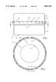
- FIG. 1is a diagrammatic illustration of a carrier assembly designed according to this invention.
- FIG. 2is a cross-sectional illustration taken along the lines 2--2 from FIG. 1.
- FIG. 3is a diagrammatic illustration of selected portions of the embodiment of FIG. 1.
- FIG. 4is an expanded view of a portion of the illustration of FIG. 2.
- FIG. 1illustrates a carrier assembly 20 that includes a first housing 22 and a second housing 24.
- Each of the housingspreferably has a generally cylindrical wall portion that extends between two ends of the housing.
- the wall portionspreferably are made of metal and have an uniform thickness.
- Each housingpreferably has at least one open end.
- the second housing 24includes a flare portion 26 that has an inner diameter that is larger compared to the remainder of the second housing 24.
- the flare portion 26receives at least a part of the first housing 22 when the two housings are interconnected.
- the second housing 24preferably includes a plurality of drive members 28 that are formed on the flare portion 26.
- the drive members 28interact with drive members 30 that are formed on the first housing 22 near the open end of the first housing.
- the most preferred embodimentincludes a series of circumferentially spaced drive members around the entire periphery of each housing. Alternatively, far fewer drive members could be used. Further, an unequal number of drive members could be provided on each housing so long as there are corresponding drive members on each housing that serve to interconnect the two housings in a manner that allows a drive torque imposed on one housing to be transferred to the other.
- the second housing 24includes an opening 32 at a lower end 34 (according to the drawing).
- the generally cylindrical wall portionpreferably includes a constant diameter in the portion that extends between the lower end 34 and the flare portion 26.
- a generally circumferential ledge 36is formed at the location where the flare portion merges with the remainder of the wall portion of the second housing 24.
- the ledge 36is useful for facilitating a proper placement of the first housing 22 within the second housing 24.
- a terminal edge on the open end of the first housing 22will be received against the ledge portion 36 on the second housing 24.
- the drive members 28 on the second housing 24are lanced and protrude radially inward from the inner surface of the flare portion 26.
- the drive members 30 on the first housing 22are lanced and protrude from the outer surface of the first housing 22. Utilizing lanced drive members instead of tangs and grooves results in a much stronger carrier assembly. Because the end of each housing has a continuous periphery, there is no longer the possibility for centrifugal forces to cause an outward distortion of the material when the carrier assembly is in use. Using lanced drive members provides the further advantage of not requiring the removal of any of the material (i.e., metal) from either housing.
- the drive members 30include a front edge 40, which preferably is generally flat and extends in a generally perpendicular direction radially away from the outer surface of the first housing 22.
- the drive members 28include front edges 42, which preferably are generally flat and extend in a generally perpendicular direction radially inward from the inner surface of the second housing 24.
- the front edges 40 on the drive members 30are placed in abutting engagement with the front edges 42 on the drive members 28 when the two housings are interconnected.
- opposing front edges 40are spaced apart by a distance indicated as D1 in FIG. 3.
- Each of the drive members 30includes a rear edge 44 opposite the front edge 40.
- the rear edge 44tapers into the outer surface on the housing 22.
- a rear edge 46 on each of the drive members 28tapers into the inner surface on the second housing 24.
- the housingsare formed to have the generally cylindrical wall portions with inner surfaces defining the inner diameters and outer surfaces defining the outer diameters of each housing.
- the drive membersare then lanced using a conventional lancing tool arrangement to form the radially outwardly projecting drive members 30.
- the flared portion 26preferably is formed prior to forming the drive members.
- the drive members 28are then formed, using a conventional lancing tool, so that they project radially inward.
- the two open ends of the housingsare interconnected so that the open end of the first housing 22 is received by the flare section 26 and the drive members 28 engage the drive members 30.
- the two housingscan be maintained in axial alignment in a conventional manner.
Landscapes
- Engineering & Computer Science (AREA)
- General Engineering & Computer Science (AREA)
- Mechanical Engineering (AREA)
- General Details Of Gearings (AREA)
Abstract
Description
Claims (20)
Priority Applications (2)
| Application Number | Priority Date | Filing Date | Title |
|---|---|---|---|
| US08/946,771US6007430A (en) | 1997-10-08 | 1997-10-08 | Two-piece carrier assembly |
| PCT/US1998/020733WO1999018370A1 (en) | 1997-10-08 | 1998-10-02 | Two-piece carrier assembly |
Applications Claiming Priority (1)
| Application Number | Priority Date | Filing Date | Title |
|---|---|---|---|
| US08/946,771US6007430A (en) | 1997-10-08 | 1997-10-08 | Two-piece carrier assembly |
Publications (1)
| Publication Number | Publication Date |
|---|---|
| US6007430Atrue US6007430A (en) | 1999-12-28 |
Family
ID=25484975
Family Applications (1)
| Application Number | Title | Priority Date | Filing Date |
|---|---|---|---|
| US08/946,771Expired - Fee RelatedUS6007430A (en) | 1997-10-08 | 1997-10-08 | Two-piece carrier assembly |
Country Status (2)
| Country | Link |
|---|---|
| US (1) | US6007430A (en) |
| WO (1) | WO1999018370A1 (en) |
Cited By (3)
| Publication number | Priority date | Publication date | Assignee | Title |
|---|---|---|---|---|
| US20040261247A1 (en)* | 2002-08-23 | 2004-12-30 | Prater Ronald E | Clutch assembly including strengthening members |
| DE102007028259A1 (en)* | 2007-06-15 | 2008-12-18 | Zf Friedrichshafen Ag | Connection between two components having a round cross-section of a transmission for absorbing axial forces |
| US20170122421A1 (en)* | 2012-01-31 | 2017-05-04 | Ford Global Technologies, Llc | Modular hybrid elextric vehicle rotor hub |
Citations (16)
| Publication number | Priority date | Publication date | Assignee | Title |
|---|---|---|---|---|
| DE515424C (en)* | 1929-07-21 | 1931-01-03 | Rheinische Metallw & Maschf | Protective cover for the hinge point of two shafts connected to one another by a universal joint, in particular of motor vehicles |
| US2262975A (en)* | 1939-01-03 | 1941-11-18 | Thermoid Company | Universal joint |
| US2547734A (en)* | 1949-06-25 | 1951-04-03 | Alfred T Barager | Cover for flexible shaft couplings |
| US3631947A (en)* | 1969-07-10 | 1972-01-04 | Borg Warner Ltd | Torque-transmitting connection and method of making the same |
| US3782355A (en)* | 1971-07-29 | 1974-01-01 | Eaton Stamping Co | Recoil starter |
| GB2045392A (en)* | 1979-03-12 | 1980-10-29 | Balboni M | Coupling for tubular elements |
| FR2466353A3 (en)* | 1979-10-02 | 1981-04-10 | Fichtel & Sachs Ag | Lightweight hub for child's bicycle - has pressed metal body with plastic moulded drive and brake elements |
| US4603555A (en)* | 1983-05-21 | 1986-08-05 | The British Petroleum Company P.L.C. | Apparatus for containing an energy storage flywheel |
| US4707034A (en)* | 1984-11-24 | 1987-11-17 | Fichtel & Sachs Ag | Hub sleeve for a bicycle hub |
| US4868963A (en)* | 1988-01-11 | 1989-09-26 | General Electric Company | Stator vane mounting method and assembly |
| US4890948A (en)* | 1985-06-20 | 1990-01-02 | Edi Bondioli | Accident preventive modular device for homokinetic, wide-angle joints intended for use in agriculture or other |
| US5267807A (en)* | 1990-11-09 | 1993-12-07 | Ford Motor Company | Driveable connection between drum components for automatic transmission friction disc clutch |
| WO1993025943A2 (en)* | 1992-06-10 | 1993-12-23 | Pavilion Technologies Inc. | Residual activation neural network |
| GB2282786A (en)* | 1993-10-16 | 1995-04-19 | Rover Group | Engine and transmission assembly. |
| US5498104A (en)* | 1994-04-29 | 1996-03-12 | Gray; Terrance H. | Leaching chamber |
| DE19543436A1 (en)* | 1995-11-22 | 1997-05-28 | Fag Automobiltechnik Ag | Front drive wheel bearing for vehicle |
Family Cites Families (1)
| Publication number | Priority date | Publication date | Assignee | Title |
|---|---|---|---|---|
| DE3802326A1 (en)* | 1988-01-27 | 1989-08-10 | Ford Werke Ag | QUICK CONNECTION BETWEEN A SHAFT AND A FITTED HUB |
- 1997
- 1997-10-08USUS08/946,771patent/US6007430A/ennot_activeExpired - Fee Related
- 1998
- 1998-10-02WOPCT/US1998/020733patent/WO1999018370A1/enactiveApplication Filing
Patent Citations (16)
| Publication number | Priority date | Publication date | Assignee | Title |
|---|---|---|---|---|
| DE515424C (en)* | 1929-07-21 | 1931-01-03 | Rheinische Metallw & Maschf | Protective cover for the hinge point of two shafts connected to one another by a universal joint, in particular of motor vehicles |
| US2262975A (en)* | 1939-01-03 | 1941-11-18 | Thermoid Company | Universal joint |
| US2547734A (en)* | 1949-06-25 | 1951-04-03 | Alfred T Barager | Cover for flexible shaft couplings |
| US3631947A (en)* | 1969-07-10 | 1972-01-04 | Borg Warner Ltd | Torque-transmitting connection and method of making the same |
| US3782355A (en)* | 1971-07-29 | 1974-01-01 | Eaton Stamping Co | Recoil starter |
| GB2045392A (en)* | 1979-03-12 | 1980-10-29 | Balboni M | Coupling for tubular elements |
| FR2466353A3 (en)* | 1979-10-02 | 1981-04-10 | Fichtel & Sachs Ag | Lightweight hub for child's bicycle - has pressed metal body with plastic moulded drive and brake elements |
| US4603555A (en)* | 1983-05-21 | 1986-08-05 | The British Petroleum Company P.L.C. | Apparatus for containing an energy storage flywheel |
| US4707034A (en)* | 1984-11-24 | 1987-11-17 | Fichtel & Sachs Ag | Hub sleeve for a bicycle hub |
| US4890948A (en)* | 1985-06-20 | 1990-01-02 | Edi Bondioli | Accident preventive modular device for homokinetic, wide-angle joints intended for use in agriculture or other |
| US4868963A (en)* | 1988-01-11 | 1989-09-26 | General Electric Company | Stator vane mounting method and assembly |
| US5267807A (en)* | 1990-11-09 | 1993-12-07 | Ford Motor Company | Driveable connection between drum components for automatic transmission friction disc clutch |
| WO1993025943A2 (en)* | 1992-06-10 | 1993-12-23 | Pavilion Technologies Inc. | Residual activation neural network |
| GB2282786A (en)* | 1993-10-16 | 1995-04-19 | Rover Group | Engine and transmission assembly. |
| US5498104A (en)* | 1994-04-29 | 1996-03-12 | Gray; Terrance H. | Leaching chamber |
| DE19543436A1 (en)* | 1995-11-22 | 1997-05-28 | Fag Automobiltechnik Ag | Front drive wheel bearing for vehicle |
Cited By (7)
| Publication number | Priority date | Publication date | Assignee | Title |
|---|---|---|---|---|
| US20040261247A1 (en)* | 2002-08-23 | 2004-12-30 | Prater Ronald E | Clutch assembly including strengthening members |
| US6945086B2 (en) | 2002-08-23 | 2005-09-20 | Koppy Corporation | Clutch assembly including strengthening members |
| US7243770B2 (en) | 2002-08-23 | 2007-07-17 | Koppy Corporation | Clutch assembly including strengthening members |
| DE102007028259A1 (en)* | 2007-06-15 | 2008-12-18 | Zf Friedrichshafen Ag | Connection between two components having a round cross-section of a transmission for absorbing axial forces |
| US7819774B2 (en) | 2007-06-15 | 2010-10-26 | Zf Friedrichshafen Ag | Connection between two transmission components having round cross-sections, for the support of axial forces |
| US20170122421A1 (en)* | 2012-01-31 | 2017-05-04 | Ford Global Technologies, Llc | Modular hybrid elextric vehicle rotor hub |
| US10731741B2 (en)* | 2012-01-31 | 2020-08-04 | Ford Global Technologies, Llc | Modular hybrid electric vehicle rotor hub |
Also Published As
| Publication number | Publication date |
|---|---|
| WO1999018370A1 (en) | 1999-04-15 |
Similar Documents
| Publication | Publication Date | Title |
|---|---|---|
| EP1141586B1 (en) | Two-piece pinion gear | |
| US4818166A (en) | Fastening a component on a shaft or in a bore against axial displacement | |
| US5607358A (en) | Connection between inner joint part and driveshaft | |
| US6910980B2 (en) | Cushion ring sprocket assembly and method | |
| US5881856A (en) | Clutch drum and method of manufacture | |
| EP0443720B1 (en) | Tapered expansion sealing plug | |
| US5896970A (en) | Clutch housing | |
| US5643092A (en) | Assembly for axially fixing a splined hub on a splined shaft | |
| US5906135A (en) | Coast clutch with power take off gear | |
| GB2111644A (en) | Connecting parts to shafts | |
| EP0444754B1 (en) | Bearings | |
| JP3340807B2 (en) | Roller bearing | |
| US6007430A (en) | Two-piece carrier assembly | |
| CA1281196C (en) | Axial retaining member and method for interconnecting male and female splined members | |
| GB2064387A (en) | Method of forming an axially directed split in a race ring for a rolling bearing and a race ring having such a split | |
| US6945086B2 (en) | Clutch assembly including strengthening members | |
| EP0444755B1 (en) | Bearings | |
| EP1094249A3 (en) | Automatic transmission | |
| US5405201A (en) | Alignment ring for split bearing race and method of assembly | |
| US5487613A (en) | Adaptor for inner bearing ring bore | |
| GB1561558A (en) | Wiper motor | |
| EP1793136A1 (en) | Method for coupling two rotational members | |
| US6238097B1 (en) | Sheet-metal cage for roller bearings | |
| JP2007263161A (en) | Shaft fitting structure | |
| US4502740A (en) | Method of making a retainer for solid type roller bearing |
Legal Events
| Date | Code | Title | Description |
|---|---|---|---|
| AS | Assignment | Owner name:KOPPY CORPORATION, MICHIGAN Free format text:ASSIGNMENT OF ASSIGNORS INTEREST;ASSIGNOR:PRATER, RONALD E.;REEL/FRAME:008770/0251 Effective date:19971007 | |
| FPAY | Fee payment | Year of fee payment:4 | |
| REMI | Maintenance fee reminder mailed | ||
| REIN | Reinstatement after maintenance fee payment confirmed | ||
| FP | Lapsed due to failure to pay maintenance fee | Effective date:20071228 | |
| FEPP | Fee payment procedure | Free format text:PETITION RELATED TO MAINTENANCE FEES GRANTED (ORIGINAL EVENT CODE: PMFG); ENTITY STATUS OF PATENT OWNER: SMALL ENTITY | |
| FEPP | Fee payment procedure | Free format text:PETITION RELATED TO MAINTENANCE FEES FILED (ORIGINAL EVENT CODE: PMFP); ENTITY STATUS OF PATENT OWNER: SMALL ENTITY | |
| REFU | Refund | Free format text:REFUND - SURCHARGE, PETITION TO ACCEPT PYMT AFTER EXP, UNINTENTIONAL (ORIGINAL EVENT CODE: R1558); ENTITY STATUS OF PATENT OWNER: SMALL ENTITY Free format text:REFUND - PAYMENT OF MAINTENANCE FEE, 8TH YR, SMALL ENTITY (ORIGINAL EVENT CODE: R2552); ENTITY STATUS OF PATENT OWNER: SMALL ENTITY | |
| FPAY | Fee payment | Year of fee payment:8 | |
| SULP | Surcharge for late payment | ||
| PRDP | Patent reinstated due to the acceptance of a late maintenance fee | Effective date:20091007 | |
| REMI | Maintenance fee reminder mailed | ||
| LAPS | Lapse for failure to pay maintenance fees | ||
| STCH | Information on status: patent discontinuation | Free format text:PATENT EXPIRED DUE TO NONPAYMENT OF MAINTENANCE FEES UNDER 37 CFR 1.362 | |
| FP | Lapsed due to failure to pay maintenance fee | Effective date:20111228 |