US6007225A - Directed lighting system utilizing a conical light deflector - Google Patents
Directed lighting system utilizing a conical light deflectorDownload PDFInfo
- Publication number
- US6007225A US6007225AUS09/034,760US3476098AUS6007225AUS 6007225 AUS6007225 AUS 6007225AUS 3476098 AUS3476098 AUS 3476098AUS 6007225 AUS6007225 AUS 6007225A
- Authority
- US
- United States
- Prior art keywords
- deflector
- light
- conical
- cone
- conical deflector
- Prior art date
- Legal status (The legal status is an assumption and is not a legal conclusion. Google has not performed a legal analysis and makes no representation as to the accuracy of the status listed.)
- Expired - Lifetime
Links
- 239000013307optical fiberSubstances0.000claimsabstractdescription28
- 238000009826distributionMethods0.000claimsabstractdescription19
- 230000003287optical effectEffects0.000claimsabstractdescription17
- 239000000835fiberSubstances0.000claimsdescription42
- 230000008878couplingEffects0.000claimsdescription9
- 238000010168coupling processMethods0.000claimsdescription9
- 238000005859coupling reactionMethods0.000claimsdescription9
- 238000002310reflectometryMethods0.000abstractdescription27
- 239000000463materialSubstances0.000description7
- 238000005286illuminationMethods0.000description6
- XAGFODPZIPBFFR-UHFFFAOYSA-NaluminiumChemical compound[Al]XAGFODPZIPBFFR-UHFFFAOYSA-N0.000description4
- 229910052782aluminiumInorganic materials0.000description4
- 150000001875compoundsChemical class0.000description3
- 230000008901benefitEffects0.000description2
- 239000011521glassSubstances0.000description2
- 238000000034methodMethods0.000description2
- 238000012986modificationMethods0.000description2
- 230000004048modificationEffects0.000description2
- 238000013459approachMethods0.000description1
- 238000000576coating methodMethods0.000description1
- 239000012141concentrateSubstances0.000description1
- 238000010276constructionMethods0.000description1
- 238000011161developmentMethods0.000description1
- 238000010586diagramMethods0.000description1
- 238000009792diffusion processMethods0.000description1
- 230000004313glareEffects0.000description1
- 238000002347injectionMethods0.000description1
- 239000007924injectionSubstances0.000description1
- 239000002991molded plasticSubstances0.000description1
- 229910052709silverInorganic materials0.000description1
- 239000004332silverSubstances0.000description1
- 239000000758substrateSubstances0.000description1
- 238000012360testing methodMethods0.000description1
- 230000007704transitionEffects0.000description1
- 238000009827uniform distributionMethods0.000description1
Images


Classifications
- G—PHYSICS
- G02—OPTICS
- G02B—OPTICAL ELEMENTS, SYSTEMS OR APPARATUS
- G02B6/00—Light guides; Structural details of arrangements comprising light guides and other optical elements, e.g. couplings
- G02B6/0001—Light guides; Structural details of arrangements comprising light guides and other optical elements, e.g. couplings specially adapted for lighting devices or systems
- G02B6/0005—Light guides; Structural details of arrangements comprising light guides and other optical elements, e.g. couplings specially adapted for lighting devices or systems the light guides being of the fibre type
- G02B6/0006—Coupling light into the fibre
- G—PHYSICS
- G02—OPTICS
- G02B—OPTICAL ELEMENTS, SYSTEMS OR APPARATUS
- G02B6/00—Light guides; Structural details of arrangements comprising light guides and other optical elements, e.g. couplings
- G02B6/24—Coupling light guides
- G02B6/26—Optical coupling means
- G02B6/262—Optical details of coupling light into, or out of, or between fibre ends, e.g. special fibre end shapes or associated optical elements
- G—PHYSICS
- G02—OPTICS
- G02B—OPTICAL ELEMENTS, SYSTEMS OR APPARATUS
- G02B6/00—Light guides; Structural details of arrangements comprising light guides and other optical elements, e.g. couplings
- G02B6/0001—Light guides; Structural details of arrangements comprising light guides and other optical elements, e.g. couplings specially adapted for lighting devices or systems
Definitions
- the present inventionrelates to a lighting system utilizing a conical light deflector, to provide efficient lighting over a narrow field of view.
- Directed lighting fixturestraditionally use a light source and a contoured reflective surface to distribute light over a desired pattern or area.
- the light sourceis an incandescent bulb
- the bulbmay have a diffuse emission pattern, and be positioned at the focal point of a reflector.
- the reflectordirects the light to the desired field of view.
- Bulbsalso have been developed that include internal reflectors to produce spotlight type distribution patterns.
- Optical fibersallow transport of light from a source to a desired location and direction of the light from an end of the fiber.
- the emission pattern from most such fiber systemsgenerally produces a pool of light from one or more fibers.
- Such fiber lighting systemsdo not provide a narrow field of view with a uniform distribution within the designated field of view.
- Disclosure of the InventionThe present invention addresses the above stated needs and provides an advance over the art by utilizing a conical deflector.
- the deflectorfor example, may have the shape of a circular cone, but the cone is truncated to have an opening at its narrow end (rather than a point).
- the deflectoris dimensioned relative to the narrow field of view and the light source to deflect light that would otherwise pass out of the desired field of view so as to illuminate the desired field of view. Virtually all of the emitted light illuminates the desired field of view, resulting in a high efficiency of illumination within that field.
- the conical deflectorprovides a substantially uniform light intensity distribution over the desired field of view.
- the opening of the narrow end of the conical deflectoris coupled to the light emitting end of one or more optical fibers.
- the angle of the cone of the deflectorcorresponds to the desired angle of the field of view.
- the inner surface of the deflectorhas a specular reflective characteristic over a substantial area thereof. The degree of specular reflectivity may vary over the length of the conical deflector.
- Alternate embodimentsutilize a combination of one or more of the conical deflectors with a source and an integrating cavity.
- the narrow end of each coneis coupled to an opening through the wall of the integrating cavity.
- the light emerging from the cavityincludes substantially all of the light emitted from the source.
- the one or more conical deflectorsdirect that light uniformly over the desired field of view.
- the sourcemay be a lamp or the like within the cavity, or the source may be the light emitting end of one or more optical fibers.
- the integrating cavitypreferably is spherical, with a diffusely reflective surface. In another embodiment with several conical deflectors, the integrating cavity is cylindrical. Other cavity shapes also may be used. In each case, the inner surface(s) of the cavity have a highly diffuse reflective characteristic.
- the inventionalso encompasses a number of techniques to further improve uniformity within the field of view produced by the conical deflector in the basic embodiments discussed above.
- One approachis to use two or more different types of reflectivity in different sections along the interior surface of the cone. For example, a section of the cone beginning adjacent the opening in the small end of the cone and extending lengthwise to approximately the middle of the cone may have either a diffuse reflectivity or a quasi-specular reflectivity. The rest of the inner cone surface, extending from the middle to the large end of the cone, would have the highly specular reflective characteristic.
- the inventionalso encompasses techniques to produce a desired shape of the field of view of the source and deflector system.
- the exemplary cone discussed above, having a circular cross-sectiontypically has a circular field of illumination.
- Cones having different cross-sectional shapesfor example oval, elliptical, triangular, rectangular or semi-circular (with a flat side) produce correspondingly shaped fields of view for illumination by the source and deflector system.
- non-circular componentssometimes give better performance than circular components.
- FIG. 1Ais a simplified cross-sectional illustration of a conical deflector utilized with an optical fiber and light source to uniformly direct the light from a fiber optic bundle into a narrow field of view.
- FIG. 1Bis an end view of the conical deflector used in the system of FIG. 1A.
- FIG. 2is a simplified cross-sectional illustration of a conical deflector utilized to uniformly direct the light from an integrating cavity into a narrow field of view.
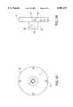
- FIG. 3is an isometric view of an optic incorporating a conical light deflector in accord with the invention.
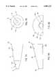
- FIGS. 4A and 4Bare end and side elevational views respectively of the fiber mount plate of the optic of FIG. 3.
- FIGS. 5A and 5Bare end and side elevational views respectively of the cone retainer plate of the optic of FIG. 3.
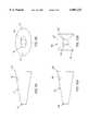
- FIG. 6is a simplified cross-sectional illustration of a conical deflector, wherein two sections of its interior surface have different light reflective characteristics.
- FIGS. 7A and 7Bare cross-section and end views of an alternate embodiment of the deflector, having a compound cone structure.
- FIGS. 8A and 8Bare cross-section and end views of an alternate embodiment of the deflector, having a semicircular cross-section.
- FIGS. 9A and 9Bare cross-section and end views of an alternate embodiment of the deflector, having an oval or elliptical cross-section.
- FIGS. 10A and 10Bare cross-section and end views of an alternate embodiment of the deflector, having a rectangular (e.g. square) cross-section.
- FIGS. 11A and 11Bare top and front cross-sectional views of another embodiment of the invention, which utilizes a cylindrical cavity in combination with a plurality of conical deflectors.
- Lighting fixtures in accord with the present inventionutilize one or more conical deflectors having a specular reflective inner surface, to efficiently direct most of the light emerging from a light source into a relatively narrow field of view.
- FIG. 1Adepicts a first embodiment of the invention.
- a lighting system 10includes an optical fiber bundle 11, a light source 12 and a light deflector 13.
- the bundle 11preferably includes a plurality of optical fibers carrying light from a lamp or other remote source 12 to the deflector 13.
- the deflector 13has the shape of a cone, in this embodiment, with a circular lateral cross section.
- the conehas two circular openings 14 and 19.
- FIG. 1Bis an end view of the cone, looking into the opening in the large end 19 showing the circular cross-section represented by the circular end openings.
- the large openingmay be covered with a transparent plate or lens, to prevent entry of dirt or debris into the cone.
- the conetapers from the large end opening 19 to the narrow end opening 14, which is adjacent to the distal end 15 of the fiber bundle 11.
- the wall(s) of the coneexpand along the length of the cone from the small end 14 to the large end 19, at an angle with respect to the longitudinal axis of the cone.
- the wall(s) of the cone 17are straight and extend at a single angle over the entire longitudinal length of the cone.
- the entire area of inner surface 17is reflective. At least a portion of the reflective surface 17 is specular.
- the shape of the cone and/or the shape of the reflective surface within the deflectormay be referred to as a truncated "right-circular cone.”
- the cone 17has a circular cross-section perpendicular to the axis of the cone at all points along the lengthwise dimension of the cone.
- the circular cone 17expands at a constant angle relative to its axis along the length of the wall of the cone, such that when viewed in longitudinal cross-section (FIG. 1), the cone 17 appears to have straight walls at an angle with respect to the central axis.
- the coneis truncated, in that it does not come to an actual point at the narrow end.
- a specular, reflective materialreflects light in such a manner that the angle of reflection of the redirected light with respect to the reflective surface has the same magnitude as the angle of incidence of the incoming light relative to that surface.
- specularcovers a range of materials and reflectivities.
- a highly specular materialhas a mirror-like finish, for example formed by silver and glass coatings or formed of highly polished aluminum.
- a quasi-specular materialwill not reflect as efficiently as a highly specular material and may cause some diffusion of the light. However, most of the reflected light will satisfy the principle that angle of reflection equals angle of incidence.
- a quasi-specular surfacemay be formed of lightly polished aluminum.
- the specular surface 17may be quasi-specular or highly specular.
- the entire inner surface 17 of the conical deflector 13has a uniform specular reflectivity.
- the proximal end of the optical fiber bundle 11receives light from the source 12.
- the fiber bundle 11carries or transmits the light from the source 12 to the distal end 15 of the bundle.
- the distal end 15 of the optical fiber bundle 15is optically coupled to the opening 14 in the narrow end of the cone.
- the lightemerges from the distal end 15 of the bundle 11 into the interior of the conical deflector 13.
- the narrow end opening 14 of the conical light deflector 13typically surrounds the distal end 15 of the fiber bundle 11. As such, all of the light emerging from the end 15 of the fiber bundle 11 passes into the interior of the conical deflector 13.
- FIG. 1Aalso provides a simplified illustration of several of the paths of light photons emitted from the fiber bundle 11. As shown at a, some portion of the emitted light emerges from the end of the bundle directly toward the desired field of view (FOV), typically on or about the axis of the deflector cone 13. Such light illuminates surfaces within that field without any reflection from the interior surface 17 of the deflector 13.
- FOVfield of view
- a photon emerging from the distal end 15 of the fiber bundle 11 in a direction substantially off-the-axis of the fibers and the conemight strike one side of the inner surface 17 of the conical deflector 13.
- the reflective inner surfacewould redirect such light back into the desired field of view of the system 10, and in some cases, in a direction somewhat closer to an angle paralleling the axis of the fiber and the cone.
- the critical feature hereis that such redirected light would remain within and illuminate the desired field of view (FOV).
- the path bshows a single such reflection to redirect the light.
- a photon emerging from the distal end 15 of the fiber bundle 11 in a direction still further off-the-axis of the fibersmight strike one side of the inner surface 17 of the conical deflector 13.
- the reflective inner surfacewould redirect such light back, but in this case, the light actually reflects off the opposite side of the conical deflector 13.
- Such photonsreflect two times (c) or more times (d) off the reflective inner surface 17 until they too are redirected back in a direction within the angle desired for the field of view (FOV).
- the redirected lightwould remain within the field of view (FOV) and, at a specified distance, would illuminate a desired footprint, e.g. on a planar surface perpendicular to the axis of the cone 17.
- the angle of the wall(s) of the conical deflector 13substantially corresponds to the angle of the desired field of view (FOV).
- FOVdesired field of view
- the reflective inner surface 17 of the deflector 13would have an angle of approximately 15° with respect to the longitudinal axis of the cone.
- the conical anglewould be approximately 24°; and for a 40° field of view the conical angle would be approximately 40°.
- the percentage of light leaving the fiber bundle 11 and subsequently emitted from the conical deflector 13 to illuminate the desired field of view (FOV)depends on the length of the conical light deflector 13, the diameter of the fiber optic bundle 11, the size and location of the specular area 17 on the surface within the cone and the degree of specular reflectivity or lack of diffuseness of that surface area.
- the length of the deflector 13preferably is chosen such that substantially all of the light emerging from the distal end 15 of the fiber bundle 11 is kept within the desired field of view (FOV).
- proposed embodiments for use with an optical fiber bundlefor example, have an 80 mm length.
- the conical light deflector 13also may be used with an optical integrating cavity, as illustrated in FIG. 2.
- the conical deflector and the light paths through that deflector illustrated in FIG. 2are generally similar to those shown in FIG. 1, and like reference characters are used for convenience.
- the integrating cavity 23takes the shape of a sphere, although other integrating cavity shapes may be used.
- the inner spherical surfaceis diffusely reflective.
- a source 21emits light into the cavity 23.
- the source 21may be a light bulb or lamp within the cavity, or the source 21 may be the distal end of a light transmitting fiber coupled from a source (recall FIG. 1A) through an opening in the wall of the cavity 23.
- the narrow end 14 of the conical light deflector 13is coupled to an opening 25 in a wall of the integrating cavity 23.
- the spherical cavity 23reflects and directs the light emitted by the source 21 through the one opening 25 in the wall of the cavity. Thus, substantially all of the light from the source 21 emerges into the cone 13 through its narrow opening 14.
- the specular inner surface 17 of the conical deflector 13directs the light, in the manner described above, to illuminate the desired field of view (FOV).
- the conical light deflector of the present inventionmay be used in a variety of lighting systems. At least one initial application is for runway lighting. In such an application, the system of the invention may be implemented with a relatively low profile, yet the system provides highly efficient lighting with a uniform intensity distribution over the desired field of view. As such, when a pilot sees the light from within the field of view of each deflector, the pilot senses substantially the same light intensity. Because the system emits relatively little light outside the field of view, the system produces minimal glare for observers in other positions.
- FIGS. 3 to 5depict a prototype of an optic 30 incorporating a conical light deflector in accord with the invention.
- This opticis designed for use with a fiber optic bundle, which provides the light to the optic.
- the optic 30efficiently illuminates a narrow field of view and provides a relatively uniform intensity distribution over the field of view, in the manner discussed above relative to the embodiment of FIG. 1.
- FIG. 3is an isometric illustration of the assembled optic 30.
- the optic 30includes a fiber mount plate 31.
- the plate 31serves as a coupler for mechanically securing the distal end of a fiber bundle in a position to optically couple light from the bundle into the interior of the conical deflector.
- the plate 31has a collar 33, and the distal end of the fiber bundle is inserted in and fastened to the collar 33.
- the optic 30also includes a cone retainer plate 35.
- the cone retainer plate 35has a tapered passage 37 therethrough.
- the large end of the conical deflector 39rests in the passage 37 and is flush with the end of the plate 35.
- the passageis dimensioned and tapers at such an angle as to closely conform to the outside surface of the large end of the conical deflector 39.
- the narrow end of the deflector cone 39fits into an opening in the fiber mount plate 31.
- Four rods 41connect the fiber mount plate 31 to the cone retainer plate 35 in such a manner as to hold the cone 39 in the position shown between the fiber mount plate 31 and the cone retainer plate 35.
- the plates 31 and 35are aluminum, although a variety of other known materials could be used.
- FIGS. 4A and 4Bprovide more detailed illustrations of the fiber mount plate 31.
- the plate 31includes four tapped holes 43 for connection of the rods 41 (FIG. 3).
- the collar 33includes a central, axial passage 44.
- the diameter of the passage 44corresponds closely to the outside diameter of the fiber bundle.
- a fastener(not shown) connects through a bore 45, to retain the distal end of the fiber bundle in the passage 44.
- the passage 44ends at a shoulder 46 that is slightly smaller in diameter than the passage 44. The shoulder serves as a stop, to accurately position the distal end of the fiber bundle.
- the passage 44provides a through-connection or coupling to a tapered opening 47.
- the dimension and taper of the opening 47correspond to those of the outside of the cone 39.
- the narrow end of the cone 39(FIG. 3) is positioned within the opening 47, when the optic 30 is assembled.
- the positioning of a fiber bundle in the passage 44 together with the location of the narrow end of the cone 39 in the opening 47provides an efficient optical coupling of light emerging from the fiber bundle into the interior of the conical deflector.
- FIG. 5Ais an end view the cone retainer plate 35 (from the side facing the fiber mount plate 31). As shown in that view, the plate 35 includes four holes 51 for passage and connection of the rods 41 (FIG. 3).
- FIG. 5Bshows the tapered passage 37 therethrough, in dotted line form.
- the large end of the cone 39rests in the passage 37 and is substantially flush with the end of the plate 35.
- the passage 37is dimensioned and tapers at such an angle as to closely conform to the outside surface of the large end of the conical deflector 39.
- the conical deflector 39exhibits a highly specular reflectivity over its entire interior surface.
- the inner surfacemay be highly polished aluminum.
- the conemay comprise a rigid substrate, typically an injection molded plastic, that is silvered and glass coated or otherwise treated to produce a mirrored finish on the interior surface.
- the interior surface of the conical deflectorincludes a specular reflective region.
- This regionmay include the entire interior surface of the cone, and the earlier views show essentially a continuous surface characteristic, intended to represent specular reflectivity that is substantially uniform over the entire surface.
- an area of one specular reflectivitymay be selected and combined with one or more areas of other reflective characteristics on the interior of the cone. The location and dimensions of regions of various reflectivity actually may be selected to produce a desired distribution of the light over the field of illumination or view, although preferably the resulting light distribution is uniform.
- the conical deflector 63 shown in FIG. 6has two regions 67A and 67B of different reflectivity.
- the portion 67A of the inner surface of the cone 63 extending lengthwise from the small end of the cone to a point near the middle of the conemay have a quasi specular reflectivity.
- the portion 67Amay have a diffuse reflective characteristic.
- the portion 67B of inner surface of the cone 63 extending lengthwise from approximately the middle of the cone to the large end of the conemay have a highly specular reflectivity.
- the portion 67Amay be highly specular, and the portion 67B may be diffuse or quasi-specular.
- FIGS. 7A and 7Bdepict another embodiment of the cone of the deflector.
- the embodiments of FIGS. 1 and 2had continuous conical walls, expanding from the small end at a predetermined angle with respect to the axis of the cone.
- the embodiment of FIGS. 7A, 7Butilizes a compound cone structure.
- the cone 70comprises two sections 71 and 72.
- the first sectionis adjacent to the small end 74 of the cone.
- the interior wallsexpand outward from the small end 74 through at a first angle with respect to the longitudinal axis of the cone (see FIG. 7A).
- the first section 71comprises approximately one-third the overall length of the cone 70, although longer or shorter first sections may be used.
- the second section 72forms the remainder of the cone 70.
- the interior wallsexpand outward as the section extends toward the large end 79 of the cone 70, but in this section the angle with respect to the longitudinal axis of the cone is different from the angle in the first section.
- the angle in the first section 71is larger, relative to the axis, than is the angle of the walls of the second section 72.
- the compound cone structure 70exhibits two different reflective regions 77A, 77B on the interior walls of the sections 71, 72 which would be visible from the field of view (see FIG. 7B). To an observer, there would appear to be a surface discontinuity at the transition between the two sections, shown as a line in FIG. 7A and as a circle in FIG. 7B. At least one of the regions has a specular reflectivity (quasi or highly specular), preferably the section 77B. The other region 77A may have the same specular reflectivity, or that region of the inner walls may have a diffuse or different degree of specular reflectivity in a manner similar to the embodiment of FIG. 6.
- FIGS. 8A and 8Bdepict another embodiment of the cone of the deflector, which has a semi-circular cross-section with a flat wall across the diameter of the semicircular cone.
- the ends 84, 89both appear as half-circles with a flat side (FIG. 8B).
- the small end 84forms a flat, half-circular end-wall, with an opening 84' cut through for coupling to the optical fiber or the integrating cavity.
- the entire end 84may form the opening, the opening 84' may have the same shape as the end wall but be slightly smaller than that wall, or as shown in FIG. 8B, the opening 84' may be circular to facilitate coupling to the end of an optical fiber.
- the interior surfaces of the deflector of FIGS. 8A, 8Binclude the inner surface 87A of the semicircular cone 83 and the inner surface 87B of the flat wall. As shown, these surfaces have a continuous specular reflective characteristic over their entire surface areas. As in the earlier embodiments, however, sections of the surfaces with specular reflectivity may be combined with other sections having diffuse reflectivity or a different degree of specular reflectivity.
- FIGS. 9A and 9Bdepict an embodiment of the cone of the deflector, which has a oval or elliptical cross-section.
- the ends 94, 99appear as ovals in the end view of FIG. 9B.
- the small end 94forms a flat, oval or elliptical end-wall, with an opening 94' cut through for coupling to the optical fiber or the integrating cavity.
- the entire end 94may be open, opening 94' may have the same shape but smaller dimensions than the end wall, or as shown in FIG. 9B, the opening 94' may be circular to facilitate coupling to the end of an optical fiber.
- the interior surface of the deflector cone 93has a continuous specular reflective characteristic over its entire surface area. As in the earlier embodiments, however, sections of the inner wall surface with specular reflectivity may be combined with other sections having different reflectivity.
- FIGS. 10A and 10Bdepict an embodiment of the cone of the deflector, which has a rectangular cross-section.
- the rectangular cross-sectionactually is square.
- the end 104may have a square opening, the same size as or smaller than the size of the end 104, for coupling to a cylindrical integrating cavity.
- the small end 104forms a flat, square end-wall, with an circular opening 104' for coupling to the end of an optical fiber or to a spherical integrating cavity.
- the interior surfaces 107 of the four walls of the deflector cone 103have a continuous specular reflective characteristic over their entire surface areas. As in the earlier embodiments, however, sections of the inner wall surfaces with specular reflectivity may be combined with other sections having different reflectivity.
- FIGS. 11A and 11Bare top and front cross-sectional views of another embodiment of the invention.
- This embodimentutilizes a cylindrical integrating cavity 123, shown as a rectangle in the top view of FIG. 11A, and shown as a circular cross-section in the front view.
- the inner surfaces of the cylindrical cavity 123are diffusely reflective.
- the present inventionmay work with multiple conical deflectors coupled to one integrating cavity.
- the deflectorsmay be arranged in a variety of patterns to connect to the cavity.
- the embodiment of FIGS. 11A, 11Bincludes two rows of deflectors 113. Each row includes four conical deflectors.
- the entire inner surface of each of the conical deflectors 113has a highly specular reflective characteristic, although combinations of highly specular, quasi-specular and diffuse materials may be used on the inner surfaces of these cones.
- the cones of the deflectorshave substantially the same shape when viewed in cross-section from the top and the side.
- the conesmay be circular in cross-section similar to FIG. 1A or square in cross-section similar to FIG. 10B.
- certain applicationsmay warrant use of other conical deflector shapes.
- the small ends of the cones in the two rowsconnect to two parallel rows of matching openings in the cylindrical wall of the cavity 123.
- a diffusely reflective baffle 125is attached to the cylindrical wall of the cavity 123.
- the system of FIGS. 11A and 11Balso may include two diffuse baffles 127 positioned at angles above the light source 121 as shown.
- the baffles 127help to diffuse the light from the source 121 throughout the cavity 121, and the baffle 125 helps to efficiently direct light from the cavity 123 through the openings into the specular interiors of the cones 113.
- a prism 129covers the four large end openings of the cones 113 in each row of cones.
- the above discussed embodimentsrepresent examples of lighting systems using conical deflectors within the scope of the invention.
- the inventionadmits of a range of modifications.
- the cones in the above discussed embodimentshave been straight cones, extending along a straight axis.
- Some applications, particularly requiring a low profile,may utilize curved or bent cone structures.
- a bent conewould extend along a first axis at one angle, and then extend from the bend along a second angle toward the desired field of view.
- Appendix 1 of the above incorporated provisional applicationshows modeling results, energy maps and schematic shape diagrams for three initial implementations of optics incorporating the conical light deflector, for use with an optical fiber bundle as the source of light for illumination of desired fields of view having three different angles of view.
- Appendix 2 of the above incorporated provisional applicationis a presentation detailing the construction and testing of those optics.
Landscapes
- Physics & Mathematics (AREA)
- General Physics & Mathematics (AREA)
- Optics & Photonics (AREA)
- Light Guides In General And Applications Therefor (AREA)
- Non-Portable Lighting Devices Or Systems Thereof (AREA)
Abstract
Description
Claims (30)
Priority Applications (3)
| Application Number | Priority Date | Filing Date | Title |
|---|---|---|---|
| US09/034,760US6007225A (en) | 1997-10-16 | 1998-03-04 | Directed lighting system utilizing a conical light deflector |
| AU96888/98AAU9688898A (en) | 1997-10-16 | 1998-10-06 | Directed lighting system utilizing a conical light deflector |
| PCT/US1998/021157WO1999020937A1 (en) | 1997-10-16 | 1998-10-06 | Directed lighting system utilizing a conical light deflector |
Applications Claiming Priority (2)
| Application Number | Priority Date | Filing Date | Title |
|---|---|---|---|
| US6223897P | 1997-10-16 | 1997-10-16 | |
| US09/034,760US6007225A (en) | 1997-10-16 | 1998-03-04 | Directed lighting system utilizing a conical light deflector |
Publications (1)
| Publication Number | Publication Date |
|---|---|
| US6007225Atrue US6007225A (en) | 1999-12-28 |
Family
ID=26711331
Family Applications (1)
| Application Number | Title | Priority Date | Filing Date |
|---|---|---|---|
| US09/034,760Expired - LifetimeUS6007225A (en) | 1997-10-16 | 1998-03-04 | Directed lighting system utilizing a conical light deflector |
Country Status (3)
| Country | Link |
|---|---|
| US (1) | US6007225A (en) |
| AU (1) | AU9688898A (en) |
| WO (1) | WO1999020937A1 (en) |
Cited By (50)
| Publication number | Priority date | Publication date | Assignee | Title |
|---|---|---|---|---|
| US6286979B1 (en) | 2000-02-24 | 2001-09-11 | David P. Ramer | Constructive occlusion lighting system with ported cavity and fan structure |
| US6332092B1 (en)* | 1998-07-08 | 2001-12-18 | Lifespex, Incorporated | Optical probe having and methods for uniform light irradiation and/or light collection over a volume |
| US6473554B1 (en) | 1996-12-12 | 2002-10-29 | Teledyne Lighting And Display Products, Inc. | Lighting apparatus having low profile |
| GB2381065A (en)* | 2001-10-05 | 2003-04-23 | Nicotech Ltd | Optical systems including conical or pyramidal reflectors |
| US6582103B1 (en) | 1996-12-12 | 2003-06-24 | Teledyne Lighting And Display Products, Inc. | Lighting apparatus |
| US20030178868A1 (en)* | 2002-03-22 | 2003-09-25 | Lapsley Robert M. | Service van |
| US20040061950A1 (en)* | 2002-09-30 | 2004-04-01 | Shih-Chou Chen | Light collimating system |
| US20040252521A1 (en)* | 2003-06-13 | 2004-12-16 | Finelite | Free-cavity, double-diffusing indirect lighting luminaire |
| US20050156103A1 (en)* | 2003-06-23 | 2005-07-21 | Advanced Optical Technologies, Llc | Integrating chamber cone light using LED sources |
| US20050161586A1 (en)* | 2003-06-23 | 2005-07-28 | Rains Jack C.Jr. | Optical integrating chamber lighting using multiple color sources |
| US6956876B1 (en)* | 2000-02-29 | 2005-10-18 | Lucent Technologies Inc. | Method and apparatus for coupling a multimode laser to a multimode fiber |
| US20060008237A1 (en)* | 2004-07-07 | 2006-01-12 | Olympus Corporation | Light guiding member, illumination apparatus, and projector |
| US7052150B2 (en)* | 1999-12-30 | 2006-05-30 | Texas Instruments Incorporated | Rod integrator |
| US7121690B1 (en) | 2004-02-26 | 2006-10-17 | Advanced Optical Technologies, Llc | Constructive occlusion with a transmissive component |
| US7144131B2 (en) | 2004-09-29 | 2006-12-05 | Advanced Optical Technologies, Llc | Optical system using LED coupled with phosphor-doped reflective materials |
| DE102005025848B3 (en)* | 2005-06-06 | 2007-02-15 | Protagon Process Technologies Gmbh | Apparatus for optically measuring an object such as a coating on an organic or polymer base |
| US20070045524A1 (en)* | 2003-06-23 | 2007-03-01 | Advanced Optical Technologies, Llc | Intelligent solid state lighting |
| US20070242441A1 (en)* | 2006-04-14 | 2007-10-18 | Renaissance Lighting, Inc. | Dual LED board layout for lighting systems |
| US20080228508A1 (en)* | 2007-03-13 | 2008-09-18 | Renaissance Lighting, Inc. | Monitoring connect time and time of operation of a solid state lighting device |
| US20090295266A1 (en)* | 2008-05-27 | 2009-12-03 | Ramer David P | Solid state lighting using light transmissive solid in or forming optical integrating volume |
| US20090296368A1 (en)* | 2008-05-27 | 2009-12-03 | Ramer David P | Solid state lighting using quantum dots in a liquid |
| US20100258828A1 (en)* | 2009-12-02 | 2010-10-14 | Renaissance Lighting Inc. | Solid state light emitter with near-uv pumped nanophosphors for producing high cri white light |
| US20100259917A1 (en)* | 2009-12-02 | 2010-10-14 | Renaissance Lighting, Inc. | Light fixture using uv solid state device and remote semiconductor nanophosphors to produce white light |
| US20100277907A1 (en)* | 2009-05-01 | 2010-11-04 | Michael Phipps | Heat sinking and flexible circuit board, for solid state light fixture utilizing an optical cavity |
| US20110108741A1 (en)* | 2009-11-12 | 2011-05-12 | Vela Technologies, Inc. | Integrating Optical System and Methods |
| US20110127555A1 (en)* | 2009-12-02 | 2011-06-02 | Renaissance Lighting, Inc. | Solid state light emitter with phosphors dispersed in a liquid or gas for producing high cri white light |
| US20110128718A1 (en)* | 2009-12-02 | 2011-06-02 | Ramer David P | Lighting fixtures using solid state device and remote phosphors to produce white light |
| US20110175528A1 (en)* | 2010-02-01 | 2011-07-21 | Renaissance Lighting, Inc. | Lamp using solid state source and doped semiconductor nanophosphor |
| US20110175520A1 (en)* | 2010-05-10 | 2011-07-21 | Renaissance Lighting, Inc. | Lighting using solid state device and phosphors to produce light approximating a black body radiation spectrum |
| US20110175510A1 (en)* | 2010-02-01 | 2011-07-21 | Benaissance Lighting, Inc. | Tubular lighting products using solid state source and semiconductor nanophosphor, e.g. for florescent tube replacement |
| US8028537B2 (en) | 2009-05-01 | 2011-10-04 | Abl Ip Holding Llc | Heat sinking and flexible circuit board, for solid state light fixture utilizing an optical cavity |
| US8118454B2 (en) | 2009-12-02 | 2012-02-21 | Abl Ip Holding Llc | Solid state lighting system with optic providing occluded remote phosphor |
| CN102449390A (en)* | 2009-04-22 | 2012-05-09 | 3M创新有限公司 | Lighting assemblies and systems |
| CN103529508A (en)* | 2013-09-12 | 2014-01-22 | 苏州佳世达光电有限公司 | Light guide device, light source assembly and projection device |
| US8702271B2 (en) | 2010-02-15 | 2014-04-22 | Abl Ip Holding Llc | Phosphor-centric control of color of light |
| US8928240B2 (en) | 2011-08-16 | 2015-01-06 | Abl Ip Holding Llc | Method and system for driving organic LED's |
| US8992043B2 (en) | 2010-02-15 | 2015-03-31 | Abl Ip Holding Llc | Constructive occlusion lighting system and applications thereof |
| WO2019106646A1 (en)* | 2017-12-03 | 2019-06-06 | Lumus Ltd. | Optical illuminator device |
| US10437031B2 (en) | 2016-11-08 | 2019-10-08 | Lumus Ltd. | Light-guide device with optical cutoff edge and corresponding production methods |
| US10564417B2 (en) | 2016-10-09 | 2020-02-18 | Lumus Ltd. | Aperture multiplier using a rectangular waveguide |
| US10809528B2 (en) | 2014-04-23 | 2020-10-20 | Lumus Ltd. | Compact head-mounted display system |
| US10962784B2 (en) | 2005-02-10 | 2021-03-30 | Lumus Ltd. | Substrate-guide optical device |
| US11243434B2 (en) | 2017-07-19 | 2022-02-08 | Lumus Ltd. | LCOS illumination via LOE |
| US11262587B2 (en) | 2018-05-22 | 2022-03-01 | Lumus Ltd. | Optical system and method for improvement of light field uniformity |
| US11389270B2 (en)* | 2020-05-01 | 2022-07-19 | Water Pik, Inc. | Button assembly for electronic device, such as oral irrigator |
| US11415812B2 (en) | 2018-06-26 | 2022-08-16 | Lumus Ltd. | Compact collimating optical device and system |
| US11523092B2 (en) | 2019-12-08 | 2022-12-06 | Lumus Ltd. | Optical systems with compact image projector |
| US11849262B2 (en) | 2019-03-12 | 2023-12-19 | Lumus Ltd. | Image projector |
| US11918530B2 (en) | 2019-02-22 | 2024-03-05 | Water Pik, Inc. | Countertop water flosser |
| US12210157B2 (en) | 2019-04-04 | 2025-01-28 | Lumus Ltd. | Air-gap free perpendicular near-eye display |
Families Citing this family (7)
| Publication number | Priority date | Publication date | Assignee | Title |
|---|---|---|---|---|
| ATE380971T1 (en)* | 1999-07-21 | 2007-12-15 | Teledyne Lighting & Display | LIGHTING DEVICE |
| DE10231325A1 (en)* | 2002-07-11 | 2004-02-12 | Hella Kg Hueck & Co. | Lighting device for vehicles |
| RU2301475C1 (en)* | 2005-12-09 | 2007-06-20 | Общество с ограниченной ответственностью Научно-производственное предприятие "Экосвет" | Light-emitting assembly, method for creating fluorescence of light-emitting assembly, and device implementing this method |
| WO2011125010A1 (en)* | 2010-04-09 | 2011-10-13 | Koninklijke Philips Electronics N.V. | Illumination system and luminaire |
| RU2442073C1 (en)* | 2011-03-30 | 2012-02-10 | Общество С Ограниченной Ответственностью "Новые Энергетические Технологии" | Method for forming light flux and illumination device |
| GB201106639D0 (en)* | 2011-04-20 | 2011-06-01 | Levon Leif | Light distribution unit |
| CN107560998B (en)* | 2017-09-01 | 2021-08-24 | 常州市武进区半导体照明应用技术研究院 | Method for adjusting irradiation uniformity of radiation light source of aging device and aging device |
Citations (18)
| Publication number | Priority date | Publication date | Assignee | Title |
|---|---|---|---|---|
| FR787117A (en)* | 1934-06-07 | 1935-09-17 | Optical warning receiver for vehicles | |
| US3234559A (en)* | 1960-05-07 | 1966-02-08 | Telefunken Patent | Multiple horn feed for parabolic reflector with phase and power adjustments |
| US3932023A (en)* | 1974-11-18 | 1976-01-13 | E. I. Du Pont De Nemours & Company | Optical coupler for transmitting light linearly between a single point and plural points |
| US4463410A (en)* | 1980-06-27 | 1984-07-31 | Kei Mori | Lighting device with dual reflecting members |
| US4735495A (en)* | 1986-12-12 | 1988-04-05 | General Electric Co. | Light source for liquid crystal display panels utilizing internally reflecting light pipes and integrating sphere |
| US4995727A (en)* | 1987-05-22 | 1991-02-26 | Minolta Camera Kabushiki Kaisha | Compact diffusion light mixing box and colorimeter |
| US5315490A (en)* | 1989-10-13 | 1994-05-24 | Bastable Rodney C | Light fittings |
| US5335158A (en)* | 1992-05-21 | 1994-08-02 | Eastman Kodak Company | High efficiency linear light source |
| US5438495A (en)* | 1989-06-16 | 1995-08-01 | Airport Technology In Scandinavia Ab | Embedded light fitting for runways |
| US5459645A (en)* | 1994-01-10 | 1995-10-17 | Delco Electronics Corporation | Wide angle light coupler for image illumination |
| US5486984A (en)* | 1991-08-19 | 1996-01-23 | Miller; Jack V. | Parabolic fiber optic luminaire |
| US5575551A (en)* | 1994-05-31 | 1996-11-19 | Nippondens Co., Ltd | Illuminating device for vehicles |
| US5629996A (en)* | 1995-11-29 | 1997-05-13 | Physical Optics Corporation | Universal remote lighting system with nonimaging total internal reflection beam transformer |
| US5676446A (en)* | 1993-11-29 | 1997-10-14 | Hughes Aircraft Company | Light cube module |
| US5692091A (en)* | 1995-09-20 | 1997-11-25 | General Electric Company | Compact optical coupling systems |
| US5727108A (en)* | 1996-09-30 | 1998-03-10 | Troy Investments, Inc. | High efficiency compound parabolic concentrators and optical fiber powered spot luminaire |
| US5730519A (en)* | 1994-11-11 | 1998-03-24 | Nippondenso Co., Ltd. | Headlight for vehicle |
| US5835648A (en)* | 1996-03-07 | 1998-11-10 | Miravant Systems, Inc. | Surface illuminator for photodynamic therapy |
- 1998
- 1998-03-04USUS09/034,760patent/US6007225A/ennot_activeExpired - Lifetime
- 1998-10-06AUAU96888/98Apatent/AU9688898A/ennot_activeAbandoned
- 1998-10-06WOPCT/US1998/021157patent/WO1999020937A1/enactiveApplication Filing
Patent Citations (18)
| Publication number | Priority date | Publication date | Assignee | Title |
|---|---|---|---|---|
| FR787117A (en)* | 1934-06-07 | 1935-09-17 | Optical warning receiver for vehicles | |
| US3234559A (en)* | 1960-05-07 | 1966-02-08 | Telefunken Patent | Multiple horn feed for parabolic reflector with phase and power adjustments |
| US3932023A (en)* | 1974-11-18 | 1976-01-13 | E. I. Du Pont De Nemours & Company | Optical coupler for transmitting light linearly between a single point and plural points |
| US4463410A (en)* | 1980-06-27 | 1984-07-31 | Kei Mori | Lighting device with dual reflecting members |
| US4735495A (en)* | 1986-12-12 | 1988-04-05 | General Electric Co. | Light source for liquid crystal display panels utilizing internally reflecting light pipes and integrating sphere |
| US4995727A (en)* | 1987-05-22 | 1991-02-26 | Minolta Camera Kabushiki Kaisha | Compact diffusion light mixing box and colorimeter |
| US5438495A (en)* | 1989-06-16 | 1995-08-01 | Airport Technology In Scandinavia Ab | Embedded light fitting for runways |
| US5315490A (en)* | 1989-10-13 | 1994-05-24 | Bastable Rodney C | Light fittings |
| US5486984A (en)* | 1991-08-19 | 1996-01-23 | Miller; Jack V. | Parabolic fiber optic luminaire |
| US5335158A (en)* | 1992-05-21 | 1994-08-02 | Eastman Kodak Company | High efficiency linear light source |
| US5676446A (en)* | 1993-11-29 | 1997-10-14 | Hughes Aircraft Company | Light cube module |
| US5459645A (en)* | 1994-01-10 | 1995-10-17 | Delco Electronics Corporation | Wide angle light coupler for image illumination |
| US5575551A (en)* | 1994-05-31 | 1996-11-19 | Nippondens Co., Ltd | Illuminating device for vehicles |
| US5730519A (en)* | 1994-11-11 | 1998-03-24 | Nippondenso Co., Ltd. | Headlight for vehicle |
| US5692091A (en)* | 1995-09-20 | 1997-11-25 | General Electric Company | Compact optical coupling systems |
| US5629996A (en)* | 1995-11-29 | 1997-05-13 | Physical Optics Corporation | Universal remote lighting system with nonimaging total internal reflection beam transformer |
| US5835648A (en)* | 1996-03-07 | 1998-11-10 | Miravant Systems, Inc. | Surface illuminator for photodynamic therapy |
| US5727108A (en)* | 1996-09-30 | 1998-03-10 | Troy Investments, Inc. | High efficiency compound parabolic concentrators and optical fiber powered spot luminaire |
Cited By (108)
| Publication number | Priority date | Publication date | Assignee | Title |
|---|---|---|---|---|
| US6473554B1 (en) | 1996-12-12 | 2002-10-29 | Teledyne Lighting And Display Products, Inc. | Lighting apparatus having low profile |
| US6582103B1 (en) | 1996-12-12 | 2003-06-24 | Teledyne Lighting And Display Products, Inc. | Lighting apparatus |
| US6647199B1 (en) | 1996-12-12 | 2003-11-11 | Teledyne Lighting And Display Products, Inc. | Lighting apparatus having low profile |
| US6332092B1 (en)* | 1998-07-08 | 2001-12-18 | Lifespex, Incorporated | Optical probe having and methods for uniform light irradiation and/or light collection over a volume |
| US7052150B2 (en)* | 1999-12-30 | 2006-05-30 | Texas Instruments Incorporated | Rod integrator |
| US20060215285A1 (en)* | 1999-12-30 | 2006-09-28 | Dewald Duane S | Rod integrators for light recycling |
| US7184213B2 (en) | 1999-12-30 | 2007-02-27 | Texas Instruments Incorporated | Rod integrators for light recycling |
| US6286979B1 (en) | 2000-02-24 | 2001-09-11 | David P. Ramer | Constructive occlusion lighting system with ported cavity and fan structure |
| US6956876B1 (en)* | 2000-02-29 | 2005-10-18 | Lucent Technologies Inc. | Method and apparatus for coupling a multimode laser to a multimode fiber |
| GB2381065A (en)* | 2001-10-05 | 2003-04-23 | Nicotech Ltd | Optical systems including conical or pyramidal reflectors |
| GB2381065B (en)* | 2001-10-05 | 2004-03-03 | Nicotech Ltd | Optical systems including reflectors |
| US20030178868A1 (en)* | 2002-03-22 | 2003-09-25 | Lapsley Robert M. | Service van |
| US20040061950A1 (en)* | 2002-09-30 | 2004-04-01 | Shih-Chou Chen | Light collimating system |
| US6788470B2 (en)* | 2002-09-30 | 2004-09-07 | Shih-Chou Chen | Light collimating system |
| US7284883B2 (en) | 2003-06-13 | 2007-10-23 | Finelite | Free-cavity, double-diffusing indirect lighting luminaire |
| US20040252521A1 (en)* | 2003-06-13 | 2004-12-16 | Finelite | Free-cavity, double-diffusing indirect lighting luminaire |
| US20060158879A1 (en)* | 2003-06-13 | 2006-07-20 | Clark Walter B | Free-cavity, double-diffusing indirect lighting luminaire |
| US7048416B2 (en) | 2003-06-13 | 2006-05-23 | Finelite, Inc. | Free-cavity, double-diffusing indirect lighting luminaire |
| US7939793B2 (en) | 2003-06-23 | 2011-05-10 | Abl Ip Holding Llc | Intelligent solid state lighting |
| US8772691B2 (en) | 2003-06-23 | 2014-07-08 | Abl Ip Holding Llc | Optical integrating cavity lighting system using multiple LED light sources |
| US20060086897A1 (en)* | 2003-06-23 | 2006-04-27 | Advanced Optical Technologies, Llc | Integrating chamber cone light using LED sources |
| US6995355B2 (en) | 2003-06-23 | 2006-02-07 | Advanced Optical Technologies, Llc | Optical integrating chamber lighting using multiple color sources |
| US20060081773A1 (en)* | 2003-06-23 | 2006-04-20 | Advanced Optical Technologies, Llc | Optical integrating chamber lighting using multiple color sources |
| US8759733B2 (en) | 2003-06-23 | 2014-06-24 | Abl Ip Holding Llc | Optical integrating cavity lighting system using multiple LED light sources with a control circuit |
| US8222584B2 (en) | 2003-06-23 | 2012-07-17 | Abl Ip Holding Llc | Intelligent solid state lighting |
| US20050156103A1 (en)* | 2003-06-23 | 2005-07-21 | Advanced Optical Technologies, Llc | Integrating chamber cone light using LED sources |
| US7145125B2 (en) | 2003-06-23 | 2006-12-05 | Advanced Optical Technologies, Llc | Integrating chamber cone light using LED sources |
| US7939794B2 (en) | 2003-06-23 | 2011-05-10 | Abl Ip Holding Llc | Intelligent solid state lighting |
| US7148470B2 (en) | 2003-06-23 | 2006-12-12 | Advanced Optical Technologies, Llc | Optical integrating chamber lighting using multiple color sources |
| US7157694B2 (en) | 2003-06-23 | 2007-01-02 | Advanced Optical Technologies, Llc | Integrating chamber cone light using LED sources |
| US7883239B2 (en) | 2003-06-23 | 2011-02-08 | Abl Ip Holding Llc | Precise repeatable setting of color characteristics for lighting applications |
| US7767948B2 (en) | 2003-06-23 | 2010-08-03 | Advanced Optical Technologies, Llc. | Optical integrating cavity lighting system using multiple LED light sources with a control circuit |
| US20070045524A1 (en)* | 2003-06-23 | 2007-03-01 | Advanced Optical Technologies, Llc | Intelligent solid state lighting |
| US7521667B2 (en) | 2003-06-23 | 2009-04-21 | Advanced Optical Technologies, Llc | Intelligent solid state lighting |
| US7497590B2 (en) | 2003-06-23 | 2009-03-03 | Advanced Optical Technologies, Llc | Precise repeatable setting of color characteristics for lighting applications |
| US20050161586A1 (en)* | 2003-06-23 | 2005-07-28 | Rains Jack C.Jr. | Optical integrating chamber lighting using multiple color sources |
| US7479622B2 (en)* | 2003-06-23 | 2009-01-20 | Advanced Optical Technologies, Llc | Integrating chamber cone light using LED sources |
| US7121690B1 (en) | 2004-02-26 | 2006-10-17 | Advanced Optical Technologies, Llc | Constructive occlusion with a transmissive component |
| WO2005106408A2 (en) | 2004-04-27 | 2005-11-10 | Advanced Optical Technologies, Llc | Optical integrating chamber lighting using multiple color sources to adjust white light |
| US7374311B2 (en) | 2004-04-27 | 2008-05-20 | Advanced Optical Technologies, Llc | Optical integrating chamber lighting using multiple color sources for luminous applications |
| WO2005105381A2 (en) | 2004-04-27 | 2005-11-10 | Advanced Optical Technologies, Llc | Precise repeatable setting of color characteristics for lighting applications |
| WO2005106963A2 (en) | 2004-04-27 | 2005-11-10 | Advanced Optical Technologies, Llc | Optical integrating chamber lighting using multiple color sources for luminous applications |
| US7604375B2 (en) | 2004-04-27 | 2009-10-20 | Advanced Optical Technologies, Llc | Optical integrating chamber lighting using one or more additional color sources to adjust white light |
| US7625098B2 (en) | 2004-04-27 | 2009-12-01 | Advanced Optical Technologies, Llc | Optical integrating chamber lighting using multiple color sources to adjust white light |
| US7195386B2 (en)* | 2004-07-07 | 2007-03-27 | Olympus Corporation | Light guiding member, illumination apparatus, and projector |
| US20060008237A1 (en)* | 2004-07-07 | 2006-01-12 | Olympus Corporation | Light guiding member, illumination apparatus, and projector |
| US8356912B2 (en) | 2004-09-29 | 2013-01-22 | Abl Ip Holding Llc | Lighting fixture using semiconductor coupled with a reflector having reflective surface with a phosphor material |
| US8360603B2 (en) | 2004-09-29 | 2013-01-29 | Abl Ip Holding Llc | Lighting fixture using semiconductor coupled with a reflector having a reflective surface with a phosphor material |
| US7144131B2 (en) | 2004-09-29 | 2006-12-05 | Advanced Optical Technologies, Llc | Optical system using LED coupled with phosphor-doped reflective materials |
| US7828459B2 (en) | 2004-09-29 | 2010-11-09 | Abl Ip Holding Llc | Lighting system using semiconductor coupled with a reflector have a reflective surface with a phosphor material |
| US10962784B2 (en) | 2005-02-10 | 2021-03-30 | Lumus Ltd. | Substrate-guide optical device |
| DE102005025848B3 (en)* | 2005-06-06 | 2007-02-15 | Protagon Process Technologies Gmbh | Apparatus for optically measuring an object such as a coating on an organic or polymer base |
| US20070242441A1 (en)* | 2006-04-14 | 2007-10-18 | Renaissance Lighting, Inc. | Dual LED board layout for lighting systems |
| US7365991B2 (en) | 2006-04-14 | 2008-04-29 | Renaissance Lighting | Dual LED board layout for lighting systems |
| US20080228508A1 (en)* | 2007-03-13 | 2008-09-18 | Renaissance Lighting, Inc. | Monitoring connect time and time of operation of a solid state lighting device |
| US8162498B2 (en) | 2008-05-27 | 2012-04-24 | Abl Ip Holding Llc | Solid state lighting using nanophosphor bearing material that is color-neutral when not excited by a solid state source |
| US20090296368A1 (en)* | 2008-05-27 | 2009-12-03 | Ramer David P | Solid state lighting using quantum dots in a liquid |
| US7980728B2 (en) | 2008-05-27 | 2011-07-19 | Abl Ip Holding Llc | Solid state lighting using light transmissive solid in or forming optical integrating volume |
| US8282241B2 (en) | 2008-05-27 | 2012-10-09 | Abl Ip Holding Llc | Solid state lighting using light transmissive solid in or forming optical integrating volume |
| US20090295266A1 (en)* | 2008-05-27 | 2009-12-03 | Ramer David P | Solid state lighting using light transmissive solid in or forming optical integrating volume |
| US8021008B2 (en) | 2008-05-27 | 2011-09-20 | Abl Ip Holding Llc | Solid state lighting using quantum dots in a liquid |
| CN102449390A (en)* | 2009-04-22 | 2012-05-09 | 3M创新有限公司 | Lighting assemblies and systems |
| US20100277907A1 (en)* | 2009-05-01 | 2010-11-04 | Michael Phipps | Heat sinking and flexible circuit board, for solid state light fixture utilizing an optical cavity |
| US8028537B2 (en) | 2009-05-01 | 2011-10-04 | Abl Ip Holding Llc | Heat sinking and flexible circuit board, for solid state light fixture utilizing an optical cavity |
| US8172424B2 (en) | 2009-05-01 | 2012-05-08 | Abl Ip Holding Llc | Heat sinking and flexible circuit board, for solid state light fixture utilizing an optical cavity |
| US20110108741A1 (en)* | 2009-11-12 | 2011-05-12 | Vela Technologies, Inc. | Integrating Optical System and Methods |
| US8854734B2 (en)* | 2009-11-12 | 2014-10-07 | Vela Technologies, Inc. | Integrating optical system and methods |
| US8201967B2 (en) | 2009-12-02 | 2012-06-19 | Abl Ip Holding Llc | Light fixture using near UV solid state device and remote semiconductor nanophosphors to produce white light |
| US20100258828A1 (en)* | 2009-12-02 | 2010-10-14 | Renaissance Lighting Inc. | Solid state light emitter with near-uv pumped nanophosphors for producing high cri white light |
| US8118454B2 (en) | 2009-12-02 | 2012-02-21 | Abl Ip Holding Llc | Solid state lighting system with optic providing occluded remote phosphor |
| US9163802B2 (en) | 2009-12-02 | 2015-10-20 | Abl Ip Holding Llc | Lighting fixtures using solid state device and remote phosphors to produce white light |
| US20100259917A1 (en)* | 2009-12-02 | 2010-10-14 | Renaissance Lighting, Inc. | Light fixture using uv solid state device and remote semiconductor nanophosphors to produce white light |
| US7845825B2 (en) | 2009-12-02 | 2010-12-07 | Abl Ip Holding Llc | Light fixture using near UV solid state device and remote semiconductor nanophosphors to produce white light |
| US8215798B2 (en) | 2009-12-02 | 2012-07-10 | Abl Ip Holding Llc | Solid state lighting system with optic providing occluded remote phosphor |
| US8217406B2 (en) | 2009-12-02 | 2012-07-10 | Abl Ip Holding Llc | Solid state light emitter with pumped nanophosphors for producing high CRI white light |
| US20110127555A1 (en)* | 2009-12-02 | 2011-06-02 | Renaissance Lighting, Inc. | Solid state light emitter with phosphors dispersed in a liquid or gas for producing high cri white light |
| US20110128718A1 (en)* | 2009-12-02 | 2011-06-02 | Ramer David P | Lighting fixtures using solid state device and remote phosphors to produce white light |
| US20110127557A1 (en)* | 2009-12-02 | 2011-06-02 | Abl Ip Holding Llc | Light fixture using near uv solid state device and remote semiconductor nanophosphors to produce white light |
| US9719012B2 (en) | 2010-02-01 | 2017-08-01 | Abl Ip Holding Llc | Tubular lighting products using solid state source and semiconductor nanophosphor, E.G. for florescent tube replacement |
| US8994269B2 (en) | 2010-02-01 | 2015-03-31 | Abl Ip Holding Llc | Lamp using solid state source |
| US20110175528A1 (en)* | 2010-02-01 | 2011-07-21 | Renaissance Lighting, Inc. | Lamp using solid state source and doped semiconductor nanophosphor |
| US8749131B2 (en) | 2010-02-01 | 2014-06-10 | Abl Ip Holding Llc | Lamp using solid state source and doped semiconductor nanophosphor |
| US8760051B2 (en) | 2010-02-01 | 2014-06-24 | Abl Ip Holding Llc | Lamp using solid state source |
| US9277607B2 (en) | 2010-02-01 | 2016-03-01 | Abl Ip Holding Llc | Lamp using solid state source |
| US8212469B2 (en) | 2010-02-01 | 2012-07-03 | Abl Ip Holding Llc | Lamp using solid state source and doped semiconductor nanophosphor |
| US20110175510A1 (en)* | 2010-02-01 | 2011-07-21 | Benaissance Lighting, Inc. | Tubular lighting products using solid state source and semiconductor nanophosphor, e.g. for florescent tube replacement |
| US8702271B2 (en) | 2010-02-15 | 2014-04-22 | Abl Ip Holding Llc | Phosphor-centric control of color of light |
| US8992043B2 (en) | 2010-02-15 | 2015-03-31 | Abl Ip Holding Llc | Constructive occlusion lighting system and applications thereof |
| US8089207B2 (en) | 2010-05-10 | 2012-01-03 | Abl Ip Holding Llc | Lighting using solid state device and phosphors to produce light approximating a black body radiation spectrum |
| WO2011142887A1 (en) | 2010-05-10 | 2011-11-17 | Abl Ip Holding Llc | Lighting using solid state device and phosphors to produce light approximating a black body radiation spectrum |
| US20110175520A1 (en)* | 2010-05-10 | 2011-07-21 | Renaissance Lighting, Inc. | Lighting using solid state device and phosphors to produce light approximating a black body radiation spectrum |
| US8334644B2 (en) | 2010-05-10 | 2012-12-18 | Abl Ip Holding Llc | Lighting using solid state device and phosphors to produce light approximating a black body radiation spectrum |
| US8928240B2 (en) | 2011-08-16 | 2015-01-06 | Abl Ip Holding Llc | Method and system for driving organic LED's |
| CN103529508A (en)* | 2013-09-12 | 2014-01-22 | 苏州佳世达光电有限公司 | Light guide device, light source assembly and projection device |
| US10908426B2 (en) | 2014-04-23 | 2021-02-02 | Lumus Ltd. | Compact head-mounted display system |
| US10809528B2 (en) | 2014-04-23 | 2020-10-20 | Lumus Ltd. | Compact head-mounted display system |
| US10564417B2 (en) | 2016-10-09 | 2020-02-18 | Lumus Ltd. | Aperture multiplier using a rectangular waveguide |
| US10437031B2 (en) | 2016-11-08 | 2019-10-08 | Lumus Ltd. | Light-guide device with optical cutoff edge and corresponding production methods |
| US11378791B2 (en) | 2016-11-08 | 2022-07-05 | Lumus Ltd. | Light-guide device with optical cutoff edge and corresponding production methods |
| US11243434B2 (en) | 2017-07-19 | 2022-02-08 | Lumus Ltd. | LCOS illumination via LOE |
| WO2019106646A1 (en)* | 2017-12-03 | 2019-06-06 | Lumus Ltd. | Optical illuminator device |
| US11262587B2 (en) | 2018-05-22 | 2022-03-01 | Lumus Ltd. | Optical system and method for improvement of light field uniformity |
| US11415812B2 (en) | 2018-06-26 | 2022-08-16 | Lumus Ltd. | Compact collimating optical device and system |
| US11918530B2 (en) | 2019-02-22 | 2024-03-05 | Water Pik, Inc. | Countertop water flosser |
| US11849262B2 (en) | 2019-03-12 | 2023-12-19 | Lumus Ltd. | Image projector |
| US12210157B2 (en) | 2019-04-04 | 2025-01-28 | Lumus Ltd. | Air-gap free perpendicular near-eye display |
| US11523092B2 (en) | 2019-12-08 | 2022-12-06 | Lumus Ltd. | Optical systems with compact image projector |
| US11389270B2 (en)* | 2020-05-01 | 2022-07-19 | Water Pik, Inc. | Button assembly for electronic device, such as oral irrigator |
Also Published As
| Publication number | Publication date |
|---|---|
| AU9688898A (en) | 1999-05-10 |
| WO1999020937A1 (en) | 1999-04-29 |
Similar Documents
| Publication | Publication Date | Title |
|---|---|---|
| US6007225A (en) | Directed lighting system utilizing a conical light deflector | |
| KR100474233B1 (en) | Optical sight optical structure | |
| US5295047A (en) | Line-of-light illuminating device | |
| JP2567552B2 (en) | Light emitting diode lamp with refractive lens element | |
| US4805984A (en) | Totally internally reflecting light conduit | |
| US7967477B2 (en) | Compact optical system and lenses for producing uniform collimated light | |
| US5343330A (en) | Double refraction and total reflection solid nonimaging lens | |
| EP3179154B1 (en) | Light guide illumination device with light divergence modifier | |
| AU730976B2 (en) | Optical coupler | |
| JP2003505835A (en) | Lighting equipment | |
| JP2000515651A (en) | Optical system for coupling light from a single optical fiber to an optical fiber bundle | |
| US11668445B2 (en) | Multi-beam vehicle light | |
| AU762579B2 (en) | Light with a light-guiding element | |
| KR0184258B1 (en) | Muliple cavity light fixture | |
| US5862277A (en) | Multiport illuminator optic design for light guides | |
| US5790723A (en) | Multiport illuminator optic design for macro-fibers | |
| US7172323B1 (en) | Light emitting diode light spreader | |
| WO2019157501A1 (en) | Luminaires for spatial dimming | |
| EP1045193A1 (en) | Lighting device for concentrating axial light with an angled converging reflector | |
| CA2210575C (en) | Light directing optical structure | |
| US20170038534A1 (en) | Systems and methods for a stellate beam splitter |
Legal Events
| Date | Code | Title | Description |
|---|---|---|---|
| AS | Assignment | Owner name:ADVANCED OPTICAL TECHNOLOGIES, L.L.C., MARYLAND Free format text:ASSIGNMENT OF ASSIGNORS INTEREST;ASSIGNORS:RAMER, DAVID P.;GREEN, ALBERT;PHILLIPS, E. ALLAN;AND OTHERS;REEL/FRAME:009354/0017;SIGNING DATES FROM 19980701 TO 19980716 | |
| STCF | Information on status: patent grant | Free format text:PATENTED CASE | |
| FEPP | Fee payment procedure | Free format text:PAYOR NUMBER ASSIGNED (ORIGINAL EVENT CODE: ASPN); ENTITY STATUS OF PATENT OWNER: LARGE ENTITY | |
| REMI | Maintenance fee reminder mailed | ||
| FPAY | Fee payment | Year of fee payment:4 | |
| SULP | Surcharge for late payment | ||
| FPAY | Fee payment | Year of fee payment:8 | |
| AS | Assignment | Owner name:NGEN II, LP, CALIFORNIA Free format text:SECURITY INTEREST;ASSIGNOR:RENAISSANCE LIGHTING, INC.;REEL/FRAME:021018/0012 Effective date:20080516 | |
| AS | Assignment | Owner name:RENAISSANCE LIGHTING, INC., VIRGINIA Free format text:RELEASE BY SECURED PARTY;ASSIGNOR:NGEN II, L.P.;REEL/FRAME:024662/0348 Effective date:20081006 | |
| AS | Assignment | Owner name:ABL IP HOLDING LLC, GEORGIA Free format text:ASSIGNMENT OF ASSIGNORS INTEREST;ASSIGNOR:ADVANCED OPTICAL TECHNOLOGIES, L.L.C.;REEL/FRAME:024823/0971 Effective date:20100723 | |
| FPAY | Fee payment | Year of fee payment:12 | |
| FEPP | Fee payment procedure | Free format text:PAYER NUMBER DE-ASSIGNED (ORIGINAL EVENT CODE: RMPN); ENTITY STATUS OF PATENT OWNER: LARGE ENTITY Free format text:PAYOR NUMBER ASSIGNED (ORIGINAL EVENT CODE: ASPN); ENTITY STATUS OF PATENT OWNER: LARGE ENTITY |