US6007190A - Ink supply system for an ink jet printer having large volume ink containers - Google Patents
Ink supply system for an ink jet printer having large volume ink containersDownload PDFInfo
- Publication number
- US6007190A US6007190AUS08/365,833US36583394AUS6007190AUS 6007190 AUS6007190 AUS 6007190AUS 36583394 AUS36583394 AUS 36583394AUS 6007190 AUS6007190 AUS 6007190A
- Authority
- US
- United States
- Prior art keywords
- ink
- ink jet
- jet
- cartridge
- channel
- Prior art date
- Legal status (The legal status is an assumption and is not a legal conclusion. Google has not performed a legal analysis and makes no representation as to the accuracy of the status listed.)
- Expired - Lifetime
Links
Images


Classifications
- B—PERFORMING OPERATIONS; TRANSPORTING
- B41—PRINTING; LINING MACHINES; TYPEWRITERS; STAMPS
- B41J—TYPEWRITERS; SELECTIVE PRINTING MECHANISMS, i.e. MECHANISMS PRINTING OTHERWISE THAN FROM A FORME; CORRECTION OF TYPOGRAPHICAL ERRORS
- B41J2/00—Typewriters or selective printing mechanisms characterised by the printing or marking process for which they are designed
- B41J2/005—Typewriters or selective printing mechanisms characterised by the printing or marking process for which they are designed characterised by bringing liquid or particles selectively into contact with a printing material
- B41J2/01—Ink jet
- B41J2/17—Ink jet characterised by ink handling
- B41J2/175—Ink supply systems ; Circuit parts therefor
- B41J2/17503—Ink cartridges
- B41J2/17513—Inner structure
- B—PERFORMING OPERATIONS; TRANSPORTING
- B41—PRINTING; LINING MACHINES; TYPEWRITERS; STAMPS
- B41J—TYPEWRITERS; SELECTIVE PRINTING MECHANISMS, i.e. MECHANISMS PRINTING OTHERWISE THAN FROM A FORME; CORRECTION OF TYPOGRAPHICAL ERRORS
- B41J2/00—Typewriters or selective printing mechanisms characterised by the printing or marking process for which they are designed
- B41J2/005—Typewriters or selective printing mechanisms characterised by the printing or marking process for which they are designed characterised by bringing liquid or particles selectively into contact with a printing material
- B41J2/01—Ink jet
- B41J2/17—Ink jet characterised by ink handling
- B41J2/175—Ink supply systems ; Circuit parts therefor
- B41J2/17503—Ink cartridges
- B41J2/17506—Refilling of the cartridge
- B41J2/17509—Whilst mounted in the printer
Definitions
- the present inventionrelates to ink jet printers.
- the inventionrelates to ink jet printers having a large-volume ink reservoir mounted at a location remote from the jet plate assembly.
- Contemporary disposable ink jet cartridgestypically include a self-contained ink reservoir, a jet plate assembly supporting plural ink jet nozzles in combination with the ink reservoir and a plurality of external electrical contacts for connecting the ink jet nozzles to driver circuitry.
- the entire cartridgemust be disposed of when the ink in the reservoir is used up without regard to whether or not the jet plate assembly remains fully functional.
- the contemporary disposable cartridgetherefore represents a considerable waste of product resulting in higher costs to the consumer both in product cost and the time involved in having to frequently replace the cartridge.
- the jet plate assemblies used in the currently available disposable ink jet cartridgesare fully operable to their original print quality specifications after the original ink reservoir has been depleted.
- Systems in which the disposable ink cartridge are refilledare, however, messy and difficult to implement because many disposable ink jet cartridges are not designed with refilling in mind.
- some ink jet cartridgeshave been designed to enable refilling, such as the ink jet cartridge disclosed by Hewlett-Packard in U.S. Pat. No. 5,280,300.
- refillable ink jet cartridgesare designed to enable refilling of the ink jet cartridge for a certain number of refills while the jet plate is still providing high quality printing capabilities. Making the cartridge easy to refill, however, does not mitigate the bother, time, and expense involved in having to refill this cartridge frequently.
- ink jet cartridge reservoiris not a satisfactory solution to problems associated with frequent replacement of or refilling of the ink jet cartridge.
- the ink jet cartridgesare generally mounted on a print carriage of the ink jet printer. Therefore, the larger the volume of ink in the ink jet cartridge, the greater the amount of weight that is required to be moved by the printer carriage holding the ink jet cartridges. The additional weight of ink in the ink jet cartridges will cause significant demands on the motor that drives the printer carriage.
- ink jet cartridgesare mounted on one side of the print carriage and cause an unbalanced load on the printer carriage which requires a counter balancing mechanism. Therefore, it is difficult to balance the need for providing a larger volume of ink to the ink jet cartridges to limit the number of times that the cartridges need to be refilled with the power consumption and loading problems that larger ink volumes cause for the printer carriage.
- a system disclosed by Laser Master Corporation in U.S. Pat. Nos. 5,369,429 and 5,367,328begins with a typical ink jet cartridge, having an ink reservoir and a jet plate assembly, mounted on a printer carriage and adds an external reservoir system which refills the ink reservoir in the ink jet cartridge as the printer is printing.
- the system disclosed in U.S. Pat. No. 5,369,429is designed to replenish the ink reservoir which is integral to the ink jet cartridge with ink from the external supply while the cartridge is printing.
- the external ink reservoir, the ink jet cartridge, and the tubing connecting the external reservoir to the ink jet cartridgeare configured to form a unitary single piece replaceable assembly.
- the volume of ink in the external reservoiris designed to be depleted when the print quality of the jet plate on the ink jet cartridge assembly has degraded to a level that may provide unsatisfactory printing results.
- the mechanism to which the tubing of the Laser Master System is mountedis an Igus chain which is a hollow plastic chain link that moves back and forth with the motion of the print carriage carrying the tubing behind it.
- the bend radius of the chainAs the Igus chain moves back and forth, it bends back upon itself, the radius of this bend is commonly referred to as the bend radius of the chain.
- the bend radius of the Igus chainis large, thus the envelope of the print housing must be increased to accommodate space for the large bend radius of the Igus chain as it bends back upon itself.
- the Igus chaindoes not move smoothly and makes a clunking noise as the chain link moves back and forth which is not desirable.
- plastic chain linkssuch as the Igus chains are also expensive.
- the present inventionis an ink jet printer which provides a continuous volume of ink to the jet plate assembly without suffering from the waste, cost and cumbersome disposal problems of the prior art systems.
- the inking systemcomprises a small removable ink jet cartridge providing a jet plate and an ink channel for directing the ink to the jet plate and a large ink reservoir permanently mounted on the ink jet printer at a location which is remote from the ink jet cartridge.
- Flexible tubing permanently mounted within the ink jet printerconnects the reservoir to the ink channel of the cartridge to enable the print carriage to move back and forth while maintaining a connection from the ink reservoir to the ink jet cartridge.
- the permanently mounted ink reservoircan be refilled with ink from time to time for the entire lifetime of the ink jet printer without needing to be replaced.
- a significant feature of the inventionis that only the ink jet cartridge needs to be replaced, because the jet plate has a finite life span during which the print quality from the jet plate is satisfactory.
- the ink jet cartridgeis removably mounted to the tubing via a quick disconnect fitting to enable easy replacement of the ink jet cartridge. Removal of the ink jet cartridge does not require the removal of other portions of the ink system in order to replace a worn out jet plate assembly. Therefore, the replacement of the jet plate assembly is easy for the user and does not require replacement of other tubing and ink reservoir means whose viable lifetime is much greater than that of the jet plate assembly.
- the ink supply system of the present inventionsubstantially reduces waste, cost and disposal problems while providing a large volume of ink to the printer and maintaining high quality printing.
- An important advantage of the ink system of the present inventionis that substantially all of the ink is stored at a remote location from the ink jet carriage assembly, thereby reducing the amount of weight attached to the carriage assembly.
- the ink jet cartridge of the inventionmaintains only a minute, constant quantity of ink proximal to the jet plate, so that the load of the ink applied to the jet plate and the weight of the ink on the printer carriage does not vary as in other disposable ink systems.
- the print carriagedoes not need to be designed to operate under high-load, i.e., ink reservoir full, and low-load, i.e., ink reservoir low, situations as with disposable ink cartridges of the prior art.
- One example of a high-load conditionwould be four ink jet cartridges with their ink reservoirs full, such that each of the cartridges weigh 78 grams.
- One example of a low-load conditionwould be four ink jet cartridges with their ink reservoirs low such that each of the cartridges weighs 16 grams.
- a weight difference per cartridge multiplied by four cartridgesis a significant loading difference to take into consideration when designing the printer.
- the motor that powers the print carriageis designed for a constant load which is much smaller than the loading of the print carriages of the prior art.
- the ink jet cartridgesare mounted on one side of the print carriage, the reduction in loading on one side of the carriage due to the reduction in ink weight in the cartridges reduces the amount of counterbalancing efforts for maintaining a balanced load.
- a further advantage of the inventionis that the ink reservoir is refillable using simple procedures and is located such that refilling of the ink reservoir is simple and does not interfere with other moving parts of the ink jet printer.
- the ink reservoiris refillable during the normal operation of the printer, i.e., printing does not have to be halted in order to refill the ink reservoir.
- FIG. 1is a front view of an ink jet printer comprising the ink supply system of the present invention.
- FIG. 2is an end view of an ink jet printer comprising the ink supply system of the present invention.
- FIG. 3is a detailed front view of an ink jet cartridge of the ink supply system of the present invention.
- FIG. 4is a rear view of the ink jet cartridge depicted in FIG. 3.
- FIG. 5is a bottom view of the ink jet cartridge depicted in FIG. 3.
- FIG. 6is a side view of the ink jet cartridge depicted in FIG. 3.
- FIG. 7is a cross sectional view of the ink jet cartridge along the line 7--7 as in FIG. 3.
- FIG. 8is an exploded cutaway view of the ink jet cartridge depicted in FIG. 3.
- FIG. 9is a view of the ink jet printer and the ink supply system of the present invention illustrating the procedure of priming of the ink supply system.
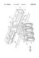
- FIG. 10is a detailed cut away view of the print carriage and the cable carrier track of the ink jet printer.
- FIG. 11is an end view of the ink supply carrier assembly.
- Encad, Inc.manufactures and sells a multi-color ink jet printer under the trade name of Nova Jet III which currently utilizes four prior art disposable ink jet cartridges.
- An operations manual of the Nova Jet III printer entitled “Nova Jet III User's Guide” (Encad Part No. 202409)is hereby incorporated by reference.
- an ink jet printer 10incorporates the invention including a housing 12 which is supported by a pair of legs 14.
- the housing 12encloses various electrical and mechanical components related to the operation of the printer device, but not directly pertinent to the present invention.
- Either a roll of continuous print media(not shown) is mounted to a rear side 16 of the printer 10 to enable a continuous supply of paper to be provided to the printer 10 or individual sheets of paper (not shown) are fed into the printer 10.
- a portion of a top side of the housing 12forms a platen 18 upon which the printing is performed by select deposition of ink droplets onto the paper.
- a continuous supply of paperis guided from the roll of paper mounted to the rear side 16 of the housing 12 and across the platen 18 by a plurality of dry rollers (not shown) which are spaced along the platen 18.
- sheets of paper or other print mediaare guided across the platen 18 by the rollers (not shown).
- a support structure 20is connected to the top side of the housing 12 with sufficient clearance between the platen 18 and the support structure 20 along a central portion of the platen 18 to enable a sheet of paper or other print media which is to be printed on to pass between the platen 18 and the support structure 20.
- the support structure 20supports a print carriage 22 above the platen 18.
- the print carriage 22includes a plurality of print head holders 24, each with a novel print head, also referred to as an ink jet cartridge, 26 mounted therein.
- four print heads 26are mounted on the print carriage 22 each containing a different color of ink.
- the four print headscontain black, magenta, cyan and yellow ink.
- the support structure 20can be formed by a variety of structural components known to those of skill in the art.
- the support structure 20generally comprises a guide rod 30 and a plurality of mounting seats 34 which support the guide rod 30 so that the guide rod 30 is positioned parallel to the platen 18.
- the print carriage 22preferably comprises a split sleeve which slidably engages the guide rod 30 to enable motion of the print carriage along the guide rod 30 to define a linear printing path, as shown by the bidirectional arrow 32, along which the print carriage 22 moves.
- a motor and a drive belt mechanism(not shown) are used to drive the print carriage 22 along the guide rod 30.
- the cable carrier track 28is preferably a U-shaped bracket having two short sides 27, 29 and a long side 25.
- the cable carrier track 28constrains the motion of a ribbon cable 31 which, as known to those in the art, transfers electronic signals to the print carriage 22 and an ink supply carrier assembly 33 to deliver ink to the print carriage 22.
- the long side 25 of the bracketis mounted to the inside of the rear wall 16 of the housing 12.
- the two short sides 27, 29 of the carrier track 28are used to contain the ink supply carrier assembly 33 and the ribbon cable 31 as the print carriage 22 moves back and forth.
- a short lip 23a, 23bis located along the edge of each of the short sides 27, 29. These lips further constrain the ink supply carrier assembly 33 and the ribbon cable 31 within the carrier track 28. The space in between the two lips 23a, 23b enable the ink supply carrier 33 and ribbon cable 31 to exit the carrier track 28 and connect to the print carriage 22 as the carriage 22 is moving back and forth along the guide rod 30.
- each of the novel print heads 26, as shown in FIGS. 1-2,is connected to a remotely located large refillable container or reservoir 36 via tubing 38.
- the tubing 38is preferably of a length which is sufficient to maintain the connection of the ink reservoir 36 to the print heads 26 while the print carriage 22 upon which the print head 26 is mounted moves along the length of the platen 18. Therefore, the length of the tubing 38 will vary depending upon the size of the plotter and the length of the carriage 22.
- the tubing 38is has an outer diameter of 0.125 inches and an inner diameter of 0.063 inches.
- the tubing lengthis 63 inches; in an E size plotter, the tubing length is 75 inches; and in a F size plotter, the tubing length is 87 inches.
- the tubing 38holds approximately 4 ml of ink along its length.
- the tubing 38 of the preferred embodimentis a bundle of four lengths of tubing which are fused together along their length which is commonly referred to as quad tubing.
- the tubing 38has a plurality of longitudinally joined flexible hollow ink tubes. The fused length of tubing is separated into four individual strands of tubing at each end for connection to each the ink jet cartridges at one end and to each of the reservoirs at the other end.
- One example of a four bundle polyurethane tubingis available as part number 4D-026-10 from Freelin-Wade Corp. located in McMinnville, Oreg.
- the quad tubing 38is a part of an ink supply carrier assembly, as illustrated in FIG. 11, which assists the smooth movement of the tubing within the printer.
- the ink supply carrier assemblyfurther comprises a curved rigid thin stainless steel blade 37 and uncoated fiberglass sleeving 35.
- the rigid thin stainless steel blade 37may also be reffered to as a resilient concavo-convex shaped spring.
- the quad tubing 38is laid against the concave side of a curved thin rigid steel blade 37.
- the blade 37has been formed from a portion of a standard Armstrong tape measure.
- the tubing 38 and the blade 37are preferably jacketed by the piece of uncoated fiber glass sleeving 35.
- the fiber glass sleeving 35is available from Alpha Wire Corp. as part number PIF-240-1/2.
- the fiber glass sleeving 35 and the tape measureare mounted at one end to the carriage 22 and at another end to the printer housing 12.
- the tubing 38is free to move within the sleeving 35 and each portion of the quad tubing 38 is mounted at one end to an ink reservoir 36 and at the other end to an ink cartridge 26.
- the ink reservoir 36is shown generally rectangular in shape. As will be recognized by those of skill in the art, the ink reservoir 36 may also take on a variety of other shapes, such as cylindrical, square, sloped, etc., depending upon the constraints of the mounting location of the reservoirs 36 on the printer 10. By way of example, in accordance with a specific embodiment of the invention, the ink reservoir 36 is a rectangular shaped reservoir having dimensions of 1.25 inches by 5.5 inches by 5 inches and holds 500 ml of ink 39. As will be recognized by those of skill in the art, the size of the ink reservoir 36 may be varied, that is, if the printer is designed for large volume printing, the reservoir size may be increased. If the printer 10 is designed for smaller print volumes, the reservoir size may be decreased. In addition, the ink reservoir 36 need not be filled to its maximum volume if the users print needs are smaller than the volume of ink held in the reservoir 36.
- each of the ink reservoirs 36is preferably positioned in a reservoir stand 40 which is attached to the rear side 16 of the housing 12.
- Ink 39 in the ink reservoir 36is delivered to its corresponding print head 26 on the printer carriage 22, utilizing a negative pressure difference developed between the print head 26 and the reservoir 36 by a priming process described in more detail below.
- the ink reservoir stand 40is mounted to the housing 12 such that the ink level in the reservoir 36 is maintained at a height differential of two to seven inches below the ink level in the print head 26 causing the ink in the ink jet cartridge 26 to be maintained at a negative pressure of between 2 in H 2 O and 7 in H 2 O. If the ink in the ink jet cartridge 26 is maintained at less than 2 in H 2 O negative pressure ink will leak from the cartridge 26. If the ink in the ink jet cartridge is maintained at more than 7 in H 2 O negative pressure insufficient ink will be delivered to the jet plate (FIG. 5) during high firing rate operations causing "ink starvation" to occur at the jet plate.
- the ink reservoir stand 40is preferably mounted to the housing 12 so that when the ink reservoirs 36 are full, the ink level of the full ink reservoir 36 is two inches below the ink level in the print head 26. As the ink 39 in the ink reservoir 36 is depleted, the height differential between the ink 39 in the ink reservoir 36 and the print head 26 will increase and, in the preferred embodiment, will not fall below seven inches when the ink reservoir 36 approaches empty.
- the print head 26, also referred to as ink jet cartridgeis much smaller than the typical ink jet cartridges of the prior art.
- the ink jet cartridgeis rectangular in shape having dimensions of approximately, 0.5 inches wide by 1.25 inched long by 1.75 inches high.
- ink jet cartridges 26 constructed in accordance with the inventionmay take on a variety of shapes depending upon the configuration of the printer carriage 22 and the profile of the printer housing 12 within which the carriage 22 is contained.
- the ink jet cartridge 26includes a cartridge housing 41, a jet plate 42, an electrical connector assembly 44, a hollow ink channel 46, a connecting tube 54 mounted within the hollow ink channel 46, and a quick disconnect fitting 48 having mating first and second portions, 50 and 52, respectively.
- the electrical connector assembly 44is positioned on the cartridge housing 41 to align with a mating electrical connector assembly (not shown) on the print head holder 24 as is conventional for ink jet printers.
- the connector assembly 44transfers electrical control signals from the main control electronics in the printer housing 12 to the jet plate 42 to control the printing operation in a manner well known in the art.
- the jet plate 42includes a plurality of ink jet nozzles which may be conventional in design. Jet plate 42 is mounted to a bottom surface of the cartridge housing 41 and in alignment with the platen 18 such that the ink 39 is ejected from the jet plate 42 for deposition onto paper or other print media which is positioned on the platen 18 below the ink jet cartridge 26.
- the connecting tube 54comprises a stainless steel tube. In an alternate embodiment, the connecting tube 54 comprises a polyurethane tube. In the preferred embodiment, the connecting tube 54 has a 0.062 inch inner diameter and a 0.125 inch outer diameter.
- the quick disconnect fitting 48is mounted atop the cartridge housing 41 and is utilized to connect the ink jet cartridge 26 to the tubing 38 to enable easy replacement of the cartridge 26.
- the quick disconnect 48includes the first portion or fitting 50, which is integral to the cartridge 26, as well as the second portion or coupling 52, bonded to the tubing 38.
- the quick disconnect fitting 48is a conventional luer-lock fitting wherein the first and second portions are mating female and male ends, 50 and 52, respectively, such as available as Part No. 71350 and Part No. 65105, respectively, from Qozina Company in Edgewood, N.Y.
- the quick disconnect fitting 48advantageously enables the easy removal of the ink jet cartridge from the tubing 38.
- the ink jet cartridge 26can be easily removed and replaced with a new cartridge having a new jet plate 42.
- the connection of the female end 50 to the male end 52 of the quick disconnect device 48includes the development of a hermetic seal between them when connected.
- a second end 62 of the tubing 38is connected to a first end of the male portion 52 of the quick disconnect fitting 48.
- An opposite end of the male portion 52 of the quick disconnect fitting 48is connected to a first end of the connecting tube 54 and a hermetic seal is formed at this connection.
- the tube 54is bonded to the male portion 52 of the quick disconnect fitting 48 by conventional bonding methods known to those of skill in the art.
- the connecting tube 54is attached to the quick disconnect fitting 48 by an adhesive bond.
- the female end 50 of the quick disconnect fitting 48is connected to an upper end 56 of the ink channel 46 and a hermetic seal is formed at this connection.
- the female portion 50 of the quick disconnect fitting 48is connected to the ink channel 46 by conventional bonding methods known to those of skill in the art.
- the female portion 50 of the quick disconnect fitting 48is attached to the upper end 56 of the ink channel 46 by an adhesive.
- the female portion 50 of the quick disconnect fitting 48is formed as an integral assembly with the upper end 56 of the ink channel 46.
- the integral molded connection of the female portion 50 of the quick disconnect fitting 48 to the upper end 56 of the ink channel 46alleviates the need for a hermetic seal to be formed at the junction of the two pieces.
- the female portion 50 of the quick disconnect fitting 48is formed as an integral assembly with the housing 41.
- a first end of the connecting tube 54is connected to the female portion 50 of the quick disconnect fitting instead of being connected to the male portion 52 of the quick disconnect fitting 48.
- a first end of the female portion 50 of the quick disconnect fitting 48is connected to the male end 52 of the quick disconnect fitting 48 and a second end of the female portion 50 of the quick disconnect fitting 48 is connected to the connecting tube 54.
- the second end of the female portion 50 of the quick disconnect fitting 48is bonded to the connecting tube 54 by conventional bonding methods known to those of skill in the art.
- the connecting tube 54is attached to the quick disconnect fitting 48 by an adhesive bond.
- the ink channel 46is generally shown as a cylindrical shaped tube. However, as known to those of skill in the art the ink channel can take on any number of shapes, such as rectangular, square, a flared cylinder, etc., which are capable of routing ink 39 to the jet plate 42.
- the ink channel 46has a 3 ml volume and contains approximately 1.5 ml of ink 39 and an air pocket 64 which contains 1.5 ml of air. Other ratios of air 64 to ink 39 are contemplated, however, a 1:1 ratio is presently preferred.
- the ink channelis rectangular in shape having inner dimensions of 0.375 inch by 0.375 inch and the outer dimensions of the rectangular channel are 0.5 inch by 0.5 inch and the rectangular channel is preferably 1.75 inches tall.
- the ink channel 46has three guiding wings extending from the ink channel 46 to aid in positioning the ink channel 46 in the housing 41. Two of the wings extend laterally from the sides of the ink channel 46 and the third wing extends orthogonal from a bottom end 58 of the ink channel 46. The laterally extending wings contact the side walls of the housing 41 and centers the ink channel 46 in the housing 41. The bottom wing contacts a surface proximal to a feeder assembly 59 for positioning the ink channel 46 and providing structural integrity for the ink channel 46.
- the volume of ink 39 maintained in the ink channel 46is not large enough to be considered a reservoir of ink 39, as this term is know in the industry.
- the volume of ink that is contained in the tubing 38is greater than the volume of ink 39 in the ink channel 46.
- the volume of ink 39 that is maintained in the ink channel 46i.e., 2 ml of ink 39, is half the amount of ink that is contained in the tubing 38, i.e., 4 ml.
- the tubing 38 and the ink channel 46provide a path for delivery of ink directly to the jet plate 42 and do not contain a "reservoir" or "supply" of ink as these terms are conventionally used in the art.
- the ink path of the ink systemis formed by inserting a first end 60 of the tubing 38 into the ink 39 contained in the ink reservoir 36.
- the first end 60 of the tubing 38is inserted into the bottom of the ink reservoir 36.
- the second end 62 of the tubing 38is connected to a first end of the male end 52 of the quick disconnect fitting 48.
- the connecting tube 54 attached to the opposite end of the male end 52 of the quick disconnect fittingis insertable into the female portion 50 of the quick disconnect fitting 48 and a hermetic connection between the female 50 and male 52 ends of the quick disconnect fitting 48 are made.
- the tube 54extends into the ink channel 46 such that an opposite end of the connecting tube 54 is proximal to a lower end 58 of the ink channel 46.
- the opposite end of the tube 54extends into the ink 39 which is maintained within the ink channel 46.
- the opposite end of the connecting tube 54terminates at a height of approximately 0.3 inches above the lower end 58 of the ink channel 46.
- the lower end 58 of the ink channel 46is connected to a feeder assembly 59 for delivering ink 39 to the jet plate 42.
- the feeder assembly 59preferably comprises a filter plate and filter chimney , as known to those of skill in the art, for delivering ink 39 to the resistor above each of the openings on the jet plate 42.
- the ink channel 46contains only a minute amount of ink 39 and the remainder of the channel 46 is filled with air 64.
- the air pocket 64 and the small quantity of ink 39act as a "buffer" between the ink 39 supplied by the external ink reservoir 36 and the ink 39 which is drawn into the jet plate 42 to absorb pressure shockwaves in the ink 39 that are caused by moving the ink 39 through the ink supply system.
- the action of drawing the ink 39 from the tubing 38 into the ink channel 46results in small pressure shockwaves that travel through the ink 39.
- the shockwavescan reflect against the walls of the tubing 38 and can build up to a significant level.
- the force of the shockwavescan actually draw the ink droplet that is to be expelled back into the jet plate 42 when the force of the shockwaves is greater than and opposite to the force of gravity on the ink drop. If the ink was supplied directly from the ink reservoir 36 through the tubing 38 and directly to the jet plate 42, these shockwaves would cause noticeable effects on the print quality.
- the small volume of ink 39 in the ink channel 46helps absorb the shockwaves in the ink 39 and transfers the shockwaves to the air pocket 64 which is formed in the ink channel 46.
- the ink 39 in the channelacts as a buffer to transfer the shockwaves in the noncompressible ink 39 caused by moving the ink 39 through the ink system to the compressible air pocket 64, thus preventing the shockwaves from effecting the print quality.
- the ink channel 46 of the present inventioncontains both a small quantity of ink 39 and a pocket of air 64 at a negative pressure relative to atmospheric pressure.
- the negative air pressureprovides tension on the ink 39, which prevents the effects of gravity from draining all of the ink 39 out of the ink jet cartridge 26.
- the pressure in the air pocket 64decreases slightly and draws ink 39 from the external ink reservoir 36 in order to return the internal air pressure to the equilibrium level.
- the small volume of ink 39 in the ink channel 46is maintained at essentially the same level throughout the operation of the ink jet cartridge 26.
- the ink system of the present inventionis a departure from ink systems of the prior art in which ink jet cartridges contain a reservoir of ink 39 which depletes over the lifetime of the ink jet cartridge.
- the ink system of the present inventiondoes not have a reservoir of ink 39 on the ink jet cartridge 26.
- the ink jet cartridge 26is not capable of printing for several reasons.
- the quantity of ink 39 maintained in the ink channel 46is insufficient to enable printing for any realistic period of time.
- the negative pressure air pocket 64 in the ink channel 46is lost because the ink channel 46 becomes open to the atmosphere . Without the negative pressure differential in the ink channel 46, the ink 39 contained in the ink channel 46 will leak out through the jet plate 42 due to gravitational effects on the ink 39 and is not capable of providing controlled printing.
- the ink supply system of the present inventionis designed such that the ink reservoir 36 and the tubing 38 are permanently mounted in the ink jet printer 10.
- the ink reservoir 36is mounted within the ink reservoir stand 40 on the rear end of the housing 12.
- the tubing 38which extends from the ink reservoir 36 is routed into the housing 12 and is positioned within the housing 12, such that the tubing 38 does not interfere with the operation of the print carriage 22.
- the tubing 38is fed into the print carriage 22 along individual channels which direct the tubing 38 proximal to its respective ink jet cartridge holder 24.
- the female end 50 of the quick disconnect fitting 48protrudes from a top end of the cartridge 26.
- the second end 62 of the tubing 38 having the male end 52 of the quick disconnect fitting 48 and the connecting tube 54 attached thereto,is positioned over the ink jet cartridge 26 such that the tube 54 is placed within the female end 50 of the quick disconnect fitting 48 as it extends from the upper end 56 of the ink jet cartridge 26.
- the male end 52 of the quick disconnect fitting 48mates with the female end 50 on the cartridge 26 and the connection of the tubing 38 is made with the ink channel 46.
- the ink jet cartridge 26can be easily disconnected from the tubing 38 via the quick disconnect fitting 48 and replaced with a new ink jet cartridge 26 having a new jet plate assembly 42.
- the ink jet cartridge 26can be quickly removed and replaced with a new cartridge 26.
- the systemis primed (i) to force the ink 39 from the reservoir 36 into the ink channel 46, (ii) to remove the excess air from the ink system and (iii) to create the desired negative pressure differential in the ink jet cartridge 26.
- ink 39 from the ink reservoir 36is advantageously delivered to the ink jet cartridge 26 without requiring any active components such as a pumping device.
- the ink from the ink reservoir 36is drawn through the tubing 38 by the negative pressure difference between the ink jet cartridge 26 and the ink reservoir 36 which acts as a siphon.
- a negative pressuremust be developed in the ink jet cartridge 26 relative to the ink reservoir 36 which remains at atmospheric pressure.
- the generation of a negative pressure within the ink jet cartridge 26is referred to as priming the ink jet cartridge 26 and can be accomplished by a variety of procedures known to those of skill in the art.
- FIG. 9illustrates one procedure for priming the ink system.
- the ink reservoir 36is positioned such that the ink level in the ink jet reservoir 26 remains at a height which is lower than the height of the ink level in the ink jet cartridge 26.
- all of the air in the tubing 38 and in the ink channel 46must be removed to create the desired suction between the ink reservoir 36 and the ink cartridge 26.
- the first end 60 of the tubing 38 which is normally positioned near the bottom of the ink reservoir 36is attached to a conventional piston assembly 66, having a piston 68 contained within a piston housing 70.
- the piston assembly 66has a hole 72 in the piston housing 70 below the level of the piston 68 in its resting position.
- the hole 72 in the housing 70is plugged by depressing a push button 78.
- the push button 78is connected to a first arm 80 which is connected at a pivot point 82 to a second arm 82.
- the push button 78is depressed, the second arm 82 actuates and a stopper 84 is inserted into the hole 72 to close the hole 72.
- the ink jet cartridge 26is removed from the print head holder 24 on the printer 22 and is turned upside down such that the jet plate assembly 42 is being held upwards.
- the jet plate assembly 42is covered with a wad of cotton 76 or other absorbent material which is held against the jet plate assembly 42 by the user's finger 78.
- the piston 68 of the piston assembly 66is pressed within the housing 70 thus (i) forcing ink through the tubing 38 into the ink channel 46 and (ii) forcing ink 39 out the jet plate 42.
- the ink 39is pushed through the tubing 38 and ink channel 46, it forces out any air that is contained in the ink system.
- the usercontinues to depress the piston 68 until all of the air is forced out of the ink system through the jet plate assembly 42 and only ink is being expelled from the jet plate 42.
- the piston 68stays above the level of the hole 72 in the piston housing 70 such that the piston 68 does not interfere with the stopper 84 in the hole 72.
- the cotton 76is removed from the jet plate 42 with all of the expelled ink 39 trapped therein and is thrown away.
- the ink jet cartridge 26is inverted back into its normal position and placed in the print head holder 24 on the printer carriage 22. The inversion of the ink jet cartridge 26 creates the air pocket 64 in the ink channel 46.
- the push button 78is retracted, the second arm 82 retracts and the stopper 84 is withdrawn from the hole 72 to open the hole 72 and the first end of the tubing 38 is open to the ink through the piston assembly 66 via the hole 72.
- the ink jet cartridge 26After priming, if the air pocket 64 is not large enough, it may be necessary to draw ink 39 out of the ink channel 46.
- the ink jet cartridge 26In order to draw ink out of the ink channel 46, the ink jet cartridge 26 remains mounted to the printer carriage (not shown) in its normal operating position while the push button 78 is depressed thus closing the hole 72 in the piston housing 70 with the stopper 84.
- the push button 78is retracted withdrawing the stopper 84 from the hole 72 in the housing 70 and the first end of the tubing 38 is open to the ink through the piston assembly 66 via the hole 72. At this point, the ink system is primed for use.
- the piston assembly 66is removed and the first end 60 of the tubing 38 is directly open to the ink 39 in the ink reservoir 36.
- the usercan refill the ink reservoir 36 through the opening to atmosphere or through a larger refill opening in the ink reservoir 36 (i) during normal printing operations without halting the current print job, (ii) without disturbing the siphon effect in the ink system and (iii) without requiring repriming of the ink supply system.
- the profile of the ink jet cartridge 26can be reduced thus allowing a slim and narrow cartridge 26 to replace the larger ink cartridges which contain a large ink reservoir thereon.
- additional cartridges 26can be added to the print carriage 22 thus enabling additional ink colors to be added without increasing the size of the carriage 22.
- the reduced size of the ink jet cartridge 26(i) lowers shipping costs of the cartridges 26, (ii) reduces the storage area required for the ink jet cartridges 26 and (iii) reduces the overall material usage to form the cartridges 26. Therefore, the ink jet cartridges 26 will be able to be offered at a lower cost to the users.
- the overall profile of the printer 10can be reduced, since the printer 10 need contain only these smaller cartridges 26.
- the overall load on the print carriage 22is reduced.
- the reduced load on the print carriage 22reduces the motor requirements to propel the print carriage 22. Since the relatively low volume of ink 39 in the ink jet cartridges 26 remains constant, the load on the printer cartridge 22 remains the same and the motor need only be designed to handle the known constant ink volume of the cartridges 26. This is advantageous over the prior art systems that had motors which were designed to operate under loads varying from four full ink jet cartridge reservoirs to four almost empty ink jet cartridge reservoirs and all variations in between, thus the motor had to be designed to over compensate for the four full cartridge condition which was a condition that only occurred for a short amount of time. By reducing the motor loading, the cost of manufacturing the ink jet printer 10 is reduced.
- the ink jet cartridges 26are mounted only on one side of the printer carriage 22 and create loading problems about the guide rod 30 which have to be compensated for.
- the torque of the printer carriage 22 about the guide rod 30 due to the weight of the ink 39 on one side of the carriage 22is substantially reduced.
- the ink volumeis maintained at a constant level, the counter balancing effects required to counteract the weight of the ink 39 need only be adapted to the known weight of the small volume of ink 39 maintained in the ink jet cartridges 26.
- the manufacturing the print carriage 22is simplified.
Landscapes
- Ink Jet (AREA)
Abstract
Description
Claims (6)
Priority Applications (1)
| Application Number | Priority Date | Filing Date | Title |
|---|---|---|---|
| US08/365,833US6007190A (en) | 1994-12-29 | 1994-12-29 | Ink supply system for an ink jet printer having large volume ink containers |
Applications Claiming Priority (1)
| Application Number | Priority Date | Filing Date | Title |
|---|---|---|---|
| US08/365,833US6007190A (en) | 1994-12-29 | 1994-12-29 | Ink supply system for an ink jet printer having large volume ink containers |
Publications (1)
| Publication Number | Publication Date |
|---|---|
| US6007190Atrue US6007190A (en) | 1999-12-28 |
Family
ID=23440553
Family Applications (1)
| Application Number | Title | Priority Date | Filing Date |
|---|---|---|---|
| US08/365,833Expired - LifetimeUS6007190A (en) | 1994-12-29 | 1994-12-29 | Ink supply system for an ink jet printer having large volume ink containers |
Country Status (1)
| Country | Link |
|---|---|
| US (1) | US6007190A (en) |
Cited By (32)
| Publication number | Priority date | Publication date | Assignee | Title |
|---|---|---|---|---|
| US6158849A (en)* | 1997-03-03 | 2000-12-12 | Hewlett Packard Company | Printer carriage alignment for periodic ink replenishment from off-carriage ink supply |
| WO2001023186A1 (en)* | 1999-09-30 | 2001-04-05 | Kimberly-Clark Worldwide, Inc. | Printhead ink delivery apparatus and method to increase the ink delivery pressure on a printhead utilizing said apparatus |
| US6338553B1 (en)* | 2000-05-15 | 2002-01-15 | Hewlett-Packard Company Intellectual Property Administration | Ink supply tube guiding system for large format printer |
| US6341853B1 (en) | 1992-12-23 | 2002-01-29 | Hewlett-Packard Company | Continuous refill of spring bag reservoir in an ink-jet swath printer/plotter |
| US20020012015A1 (en)* | 2000-05-18 | 2002-01-31 | Seiko Epson Corporation | Mounting structure, module, and liquid container |
| US20020015084A1 (en)* | 2000-06-15 | 2002-02-07 | Seiko Epson Corporation | Liquid charging method, liquid container, and method for manufacturing the same |
| WO2002034524A2 (en) | 2000-10-23 | 2002-05-02 | Aprion Digital Ltd. | Apparatus and method for protecting printing heads |
| WO2002049846A1 (en)* | 2000-12-19 | 2002-06-27 | Hewlett-Packard Company | Carriages for printing devices |
| US20020105555A1 (en)* | 2000-05-18 | 2002-08-08 | Kenji Tsukada | Ink consumption detecting method, and ink jet recording apparatus |
| USD466553S1 (en) | 2001-11-15 | 2002-12-03 | Yi-Tsung Yan | Refilling needle for inkjet cartridge |
| US20030095157A1 (en)* | 2000-04-06 | 2003-05-22 | Michael Comer | Printing systems accessible from remote locations |
| US20030117451A1 (en)* | 1999-05-20 | 2003-06-26 | Seiko Epson Corporation | Liquid container having liquid consumption detecting device |
| US6637864B2 (en)* | 2001-01-16 | 2003-10-28 | Eastman Kodak Company | Ink supply system for an ink jet printer |
| US6729184B2 (en) | 2000-07-28 | 2004-05-04 | Seiko Epson Corporation | Detector of liquid consumption condition |
| US6776478B1 (en) | 2003-06-18 | 2004-08-17 | Lexmark International, Inc. | Ink source regulator for an inkjet printer |
| US6786580B1 (en) | 2003-06-18 | 2004-09-07 | Lexmark International, Inc. | Submersible ink source regulator for an inkjet printer |
| US6793305B2 (en) | 2000-05-18 | 2004-09-21 | Seiko Epson Corporation | Method and apparatus for detecting consumption of ink |
| US6796644B1 (en) | 2003-06-18 | 2004-09-28 | Lexmark International, Inc. | Ink source regulator for an inkjet printer |
| US6817707B1 (en) | 2003-06-18 | 2004-11-16 | Lexmark International, Inc. | Pressure controlled ink jet printhead assembly |
| US20040257413A1 (en)* | 2003-06-18 | 2004-12-23 | Anderson James D. | Ink source regulator for an inkjet printer |
| US20050195252A1 (en)* | 2004-03-05 | 2005-09-08 | Brother Kogyo Kabushiki Kaisha | Image recording apparatus |
| US20050275671A1 (en)* | 2004-04-08 | 2005-12-15 | Seiko Epson Corporation | Duct connecting structure |
| US20060023009A1 (en)* | 2000-07-07 | 2006-02-02 | Seiko Epson Corporation | Liquid container, ink jet recording apparatus, apparatus and method for controlling the same, apparatus and method for detecting liquid consumption state |
| US20060274128A1 (en)* | 2000-05-18 | 2006-12-07 | Seiko Epson Corporation | Ink consumption detecting method, and ink jet recording apparatus |
| US7147314B2 (en) | 2003-06-18 | 2006-12-12 | Lexmark International, Inc. | Single piece filtration for an ink jet print head |
| US7311389B1 (en) | 2005-02-09 | 2007-12-25 | Tarry Pidgeon | Ink maintenance system for ink jet cartridges |
| US20080128353A1 (en)* | 2005-01-06 | 2008-06-05 | Andelman Marc D | Surfactant Combined Flow Through Capacitor |
| US20090100520A1 (en)* | 2007-10-12 | 2009-04-16 | Microsoft Corporation | Detection and dynamic alteration of execution of potential software threats |
| US20130135414A1 (en)* | 2011-11-25 | 2013-05-30 | Ricoh Company, Ltd. | Image forming device |
| JP2013166302A (en)* | 2012-02-15 | 2013-08-29 | Seiko Epson Corp | Inkjet recording apparatus |
| US20140147580A1 (en)* | 2011-04-04 | 2014-05-29 | Smartwater Technology Limited | Method of manufacturing a cable |
| US10265963B2 (en)* | 2015-09-28 | 2019-04-23 | Sicpa Holding Sa | Continuously refillable ink-jet cartridge |
Citations (89)
| Publication number | Priority date | Publication date | Assignee | Title |
|---|---|---|---|---|
| US2916055A (en)* | 1955-05-09 | 1959-12-08 | Moore & Co Samuel | Extruded tubing sheath |
| US3461337A (en)* | 1964-08-15 | 1969-08-12 | Nippon Electric Co | Electron discharge device filament structure |
| US3708798A (en)* | 1971-12-23 | 1973-01-02 | Ibm | Ink distribution for non-impact printing recorder |
| US3967286A (en)* | 1973-12-28 | 1976-06-29 | Facit Aktiebolag | Ink supply arrangement for ink jet printers |
| US4074284A (en)* | 1976-06-07 | 1978-02-14 | Silonics, Inc. | Ink supply system and print head |
| US4126868A (en)* | 1975-09-29 | 1978-11-21 | Siemens Aktiengesellschaft | Air venting device for ink supply systems of ink mosaic printers |
| US4178595A (en)* | 1977-11-04 | 1979-12-11 | Ricoh Company, Ltd. | Ink jet printing apparatus with ink replenishing |
| US4183131A (en)* | 1977-03-01 | 1980-01-15 | Hitachi, Ltd. | Process of manufacturing a centrifugal angular advance device for an internal combustion engine |
| US4187511A (en)* | 1978-03-20 | 1980-02-05 | Centronics Data Computer Corp. | Method and apparatus for filling the movable reservoir of an inkjet printer |
| US4342042A (en)* | 1980-12-19 | 1982-07-27 | Pitney Bowes Inc. | Ink supply system for an array of ink jet heads |
| JPS57210879A (en)* | 1981-06-23 | 1982-12-24 | Nippon Telegr & Teleph Corp <Ntt> | Ink feeding and collecting pipe and manufacture thereof |
| US4383263A (en)* | 1980-05-20 | 1983-05-10 | Canon Kabushiki Kaisha | Liquid ejecting apparatus having a suction mechanism |
| US4394669A (en)* | 1980-07-22 | 1983-07-19 | Canon Kabushiki Kaisha | Liquid jet recording apparatus |
| US4399446A (en)* | 1982-01-18 | 1983-08-16 | The Mead Corporation | Ink supply system for an ink jet printer |
| US4403233A (en)* | 1981-02-06 | 1983-09-06 | Canon Kabushiki Kaisha | Ink jet apparatus |
| US4429320A (en)* | 1979-09-21 | 1984-01-31 | Canon Kabushiki Kaisha | Ink jet recording apparatus |
| US4432005A (en)* | 1982-05-10 | 1984-02-14 | Advanced Color Technology, Inc. | Ink control system for ink jet printer |
| US4433341A (en)* | 1982-06-07 | 1984-02-21 | Ncr Corporation | Ink level control for ink jet printer |
| US4437104A (en)* | 1982-05-10 | 1984-03-13 | Advanced Color Technology, Inc. | Ink disposal system for ink jet printer |
| US4462037A (en)* | 1982-06-07 | 1984-07-24 | Ncr Corporation | Ink level control for ink jet printer |
| US4475116A (en)* | 1981-09-24 | 1984-10-02 | Olympia Werke Ag | Ink printer equipped with an ink printing head and intermediate ink container disposed on a movable carriage |
| JPS59194854A (en)* | 1983-04-19 | 1984-11-05 | Canon Inc | Ink tank for inkjet printer |
| US4500895A (en)* | 1983-05-02 | 1985-02-19 | Hewlett-Packard Company | Disposable ink jet head |
| US4509062A (en)* | 1982-11-23 | 1985-04-02 | Hewlett-Packard Company | Ink reservoir with essentially constant negative back pressure |
| US4513297A (en)* | 1982-05-27 | 1985-04-23 | Canon Kabushiki Kaisha | Ink jet printer reservoir |
| US4527175A (en)* | 1981-12-02 | 1985-07-02 | Matsushita Electric Industrial Company, Limited | Ink supply system for nonimpact printers |
| US4558326A (en)* | 1982-09-07 | 1985-12-10 | Konishiroku Photo Industry Co., Ltd. | Purging system for ink jet recording apparatus |
| JPS6163455A (en)* | 1984-09-05 | 1986-04-01 | Konishiroku Photo Ind Co Ltd | Ink jet recording apparatus |
| US4593294A (en)* | 1985-04-22 | 1986-06-03 | Exxon Printing Systems, Inc. | Ink jet method and apparatus |
| US4610202A (en)* | 1983-12-26 | 1986-09-09 | Canon Kabushiki Kaisha | Ink reservoir |
| US4611656A (en)* | 1985-01-14 | 1986-09-16 | Kendall Jr Clarence E | Protective jacket assembly |
| US4623905A (en)* | 1982-12-15 | 1986-11-18 | Canon Kabushiki Kaisha | Liquid supply apparatus |
| US4631556A (en)* | 1983-05-11 | 1986-12-23 | Canon Kabushiki Kaisha | Liquid jet recording apparatus |
| US4636814A (en)* | 1983-08-02 | 1987-01-13 | Canon Kabushiki Kaisha | Printing apparatus |
| US4639738A (en)* | 1985-04-12 | 1987-01-27 | Eastman Kodak Company | Ink level detection system for ink jet printing apparatus |
| US4677448A (en)* | 1982-05-11 | 1987-06-30 | Canon Kabushiiki Kaisha | Recording apparatus with a carriage-mounted ink tank and overflow tank |
| US4680696A (en)* | 1983-12-26 | 1987-07-14 | Canon Kabushiki Kaisha | Ink jet recorder with improved system for transporting ink to or from recording heads |
| US4684962A (en)* | 1984-12-28 | 1987-08-04 | Canon Kabushiki Kaisha | Ink tube connecting system in a liquid jet recording apparatus |
| US4714937A (en)* | 1986-10-02 | 1987-12-22 | Hewlett-Packard Company | Ink delivery system |
| JPS6364751A (en)* | 1986-09-08 | 1988-03-23 | Hitachi Ltd | Recording head for inkjet printers |
| US4734711A (en)* | 1986-12-22 | 1988-03-29 | Eastman Kodak Company | Pressure regulation system for multi-head ink jet printing apparatus |
| US4737801A (en)* | 1985-07-24 | 1988-04-12 | Canon Kabushiki Kaisha | Ink supply device and an ink jet recording apparatus having the ink supply device |
| JPS63120655A (en)* | 1986-11-10 | 1988-05-25 | Canon Inc | liquid jet recording device |
| US4750005A (en)* | 1986-12-22 | 1988-06-07 | Eastman Kodak Company | Continuous ink jet printer's selectable ink circulation subsystems |
| JPS63147651A (en)* | 1986-12-12 | 1988-06-20 | Canon Inc | liquid jet recording device |
| US4757331A (en)* | 1985-03-19 | 1988-07-12 | Canon Kabuskiki Kaisha | Recorder having ink supply means for movable ink tank |
| US4775871A (en)* | 1984-12-28 | 1988-10-04 | Canon Kabushiki Kaisha | Ink jet recording apparatus having a flexible ink supply connection |
| US4791438A (en)* | 1987-10-28 | 1988-12-13 | Hewlett-Packard Company | Balanced capillary ink jet pen for ink jet printing systems |
| US4794409A (en)* | 1987-12-03 | 1988-12-27 | Hewlett-Packard Company | Ink jet pen having improved ink storage and distribution capabilities |
| US4823146A (en)* | 1986-02-14 | 1989-04-18 | Dataproducts Corporation | Cartridge and method of using a cartridge for phase change ink in an ink jet apparatus |
| US4831389A (en)* | 1987-12-21 | 1989-05-16 | Hewlett-Packard Company | Off board ink supply system and process for operating an ink jet printer |
| US4885595A (en)* | 1989-02-14 | 1989-12-05 | Hewlett-Packard Company | Multicomponent refillable toner delivery system |
| JPH0217257A (en)* | 1988-07-06 | 1990-01-22 | Nissan Motor Co Ltd | Automatic transmission line pressure control device |
| US4921811A (en)* | 1982-11-24 | 1990-05-01 | Hitachi, Ltd. | Semiconductor integrated circuit device and a method for manufacturing the same |
| US4926196A (en)* | 1986-12-25 | 1990-05-15 | Canon Kabushiki Kaisha | Ink jet printer |
| US4929963A (en)* | 1988-09-02 | 1990-05-29 | Hewlett-Packard Company | Ink delivery system for inkjet printer |
| US4931811A (en)* | 1989-01-31 | 1990-06-05 | Hewlett-Packard Company | Thermal ink jet pen having a feedtube with improved sizing and operational with a minimum of depriming |
| US4931812A (en)* | 1989-07-18 | 1990-06-05 | Hewlett-Packard Company | Flow control system for ink cartridges |
| JPH02217257A (en)* | 1989-02-17 | 1990-08-30 | Canon Inc | Ink jet recording device |
| US4959667A (en)* | 1989-02-14 | 1990-09-25 | Hewlett-Packard Company | Refillable ink bag |
| US4967207A (en)* | 1989-07-26 | 1990-10-30 | Hewlett-Packard Company | Ink jet printer with self-regulating refilling system |
| US4968998A (en)* | 1989-07-26 | 1990-11-06 | Hewlett-Packard Company | Refillable ink jet print system |
| US4973993A (en)* | 1989-07-11 | 1990-11-27 | Hewlett-Packard Company | Ink-quantity and low ink sensing for ink-jet printers |
| US4977413A (en)* | 1987-04-15 | 1990-12-11 | Canon Kabushiki Kaisha | Ink remain detector having a flexible member and a liquid injection recording apparatus utilizing the detector |
| US4992802A (en)* | 1988-12-22 | 1991-02-12 | Hewlett-Packard Company | Method and apparatus for extending the environmental operating range of an ink jet print cartridge |
| US4999652A (en)* | 1987-12-21 | 1991-03-12 | Hewlett-Packard Company | Ink supply apparatus for rapidly coupling and decoupling a remote ink source to a disposable ink jet pen |
| US5021809A (en)* | 1986-11-19 | 1991-06-04 | Canon Kabushiki Kaisha | Ink jet recording device with pressure-fluctuation absorption |
| US5025270A (en)* | 1988-06-27 | 1991-06-18 | Seiko Instruments, Inc. | Recording apparatus coupled ink supply tubes |
| US5040001A (en)* | 1990-06-27 | 1991-08-13 | Hewlett-Packard Company | Collapsible storage bladder for ink cartridges |
| US5051759A (en)* | 1989-01-13 | 1991-09-24 | Canon Kabushiki Kaisha | Ink jet cartridge and ink tank |
| US5079570A (en)* | 1989-10-18 | 1992-01-07 | Hewlett-Packard Company | Capillary reservoir binary ink level sensor |
| JPH0425465A (en)* | 1990-05-22 | 1992-01-29 | Canon Inc | inkjet recording device |
| US5101219A (en)* | 1990-04-12 | 1992-03-31 | Gerber Garment Technology, Inc. | Long life pen and ink supply unit for x,y plotter and the like and related method of use |
| US5136305A (en)* | 1990-12-06 | 1992-08-04 | Xerox Corporation | Ink jet printer with ink supply monitoring means |
| US5159348A (en)* | 1990-10-29 | 1992-10-27 | Xerox Corporation | Ink jet printing apparatus |
| US5182579A (en)* | 1990-07-10 | 1993-01-26 | Canon Kabushiki Kaisha | Ink-jet having ink storing absorbant material |
| US5187498A (en)* | 1991-07-24 | 1993-02-16 | Xerox Corporation | Ink supply container and system |
| US5189438A (en)* | 1989-03-06 | 1993-02-23 | Spectra, Inc. | Dual reservoir and valve system for an ink jet head |
| US5221936A (en)* | 1987-04-03 | 1993-06-22 | Canon Kabushiki Kaisha | Ink tank having a vent path opened and closed by a movable magnetic member |
| JPH05162326A (en)* | 1991-12-11 | 1993-06-29 | Canon Inc | ink cartridge |
| US5233369A (en)* | 1990-12-27 | 1993-08-03 | Xerox Corporation | Method and apparatus for supplying ink to an ink jet printer |
| US5245360A (en)* | 1983-12-26 | 1993-09-14 | Canon Kabushiki Kaisha | Ink jet apparatus capable of mounting an ink tank and ink for use in same |
| US5245365A (en)* | 1990-02-28 | 1993-09-14 | Compaq Computer Corporation | Ink-jet printer with user replaceable printing system cartridge |
| US5280300A (en)* | 1991-08-27 | 1994-01-18 | Hewlett-Packard Company | Method and apparatus for replenishing an ink cartridge |
| US5289211A (en)* | 1991-04-15 | 1994-02-22 | Ing. S. Olivetti & C., S.p.A. | Ink detecting device for a liquid-ink printing element |
| US5311214A (en)* | 1985-11-08 | 1994-05-10 | Canon Kabushiki Kaisha | Ink jet recording apparatus having means for removing foreign material from an ink supply path by first introducing an into the ink supply path |
| US5367328A (en)* | 1993-10-20 | 1994-11-22 | Lasermaster Corporation | Automatic ink refill system for disposable ink jet cartridges |
| US5454409A (en)* | 1991-02-15 | 1995-10-03 | Waverly Pharmaceutical, Ltd. | Transfer adaptors |
| US5469201A (en)* | 1993-10-20 | 1995-11-21 | Lasermaster Corporation | Ink supply line support system for a continuous ink refill system for disosable ink jet cartridges |
- 1994
- 1994-12-29USUS08/365,833patent/US6007190A/ennot_activeExpired - Lifetime
Patent Citations (90)
| Publication number | Priority date | Publication date | Assignee | Title |
|---|---|---|---|---|
| US2916055A (en)* | 1955-05-09 | 1959-12-08 | Moore & Co Samuel | Extruded tubing sheath |
| US3461337A (en)* | 1964-08-15 | 1969-08-12 | Nippon Electric Co | Electron discharge device filament structure |
| US3708798A (en)* | 1971-12-23 | 1973-01-02 | Ibm | Ink distribution for non-impact printing recorder |
| US3967286A (en)* | 1973-12-28 | 1976-06-29 | Facit Aktiebolag | Ink supply arrangement for ink jet printers |
| US4126868A (en)* | 1975-09-29 | 1978-11-21 | Siemens Aktiengesellschaft | Air venting device for ink supply systems of ink mosaic printers |
| US4074284A (en)* | 1976-06-07 | 1978-02-14 | Silonics, Inc. | Ink supply system and print head |
| US4183131A (en)* | 1977-03-01 | 1980-01-15 | Hitachi, Ltd. | Process of manufacturing a centrifugal angular advance device for an internal combustion engine |
| US4178595A (en)* | 1977-11-04 | 1979-12-11 | Ricoh Company, Ltd. | Ink jet printing apparatus with ink replenishing |
| US4187511A (en)* | 1978-03-20 | 1980-02-05 | Centronics Data Computer Corp. | Method and apparatus for filling the movable reservoir of an inkjet printer |
| US4429320A (en)* | 1979-09-21 | 1984-01-31 | Canon Kabushiki Kaisha | Ink jet recording apparatus |
| US4383263A (en)* | 1980-05-20 | 1983-05-10 | Canon Kabushiki Kaisha | Liquid ejecting apparatus having a suction mechanism |
| US4394669A (en)* | 1980-07-22 | 1983-07-19 | Canon Kabushiki Kaisha | Liquid jet recording apparatus |
| US4342042A (en)* | 1980-12-19 | 1982-07-27 | Pitney Bowes Inc. | Ink supply system for an array of ink jet heads |
| US4403233A (en)* | 1981-02-06 | 1983-09-06 | Canon Kabushiki Kaisha | Ink jet apparatus |
| JPS57210879A (en)* | 1981-06-23 | 1982-12-24 | Nippon Telegr & Teleph Corp <Ntt> | Ink feeding and collecting pipe and manufacture thereof |
| US4475116A (en)* | 1981-09-24 | 1984-10-02 | Olympia Werke Ag | Ink printer equipped with an ink printing head and intermediate ink container disposed on a movable carriage |
| US4527175A (en)* | 1981-12-02 | 1985-07-02 | Matsushita Electric Industrial Company, Limited | Ink supply system for nonimpact printers |
| US4399446A (en)* | 1982-01-18 | 1983-08-16 | The Mead Corporation | Ink supply system for an ink jet printer |
| US4432005A (en)* | 1982-05-10 | 1984-02-14 | Advanced Color Technology, Inc. | Ink control system for ink jet printer |
| US4437104A (en)* | 1982-05-10 | 1984-03-13 | Advanced Color Technology, Inc. | Ink disposal system for ink jet printer |
| US4677448A (en)* | 1982-05-11 | 1987-06-30 | Canon Kabushiiki Kaisha | Recording apparatus with a carriage-mounted ink tank and overflow tank |
| US4513297A (en)* | 1982-05-27 | 1985-04-23 | Canon Kabushiki Kaisha | Ink jet printer reservoir |
| US4433341A (en)* | 1982-06-07 | 1984-02-21 | Ncr Corporation | Ink level control for ink jet printer |
| US4462037A (en)* | 1982-06-07 | 1984-07-24 | Ncr Corporation | Ink level control for ink jet printer |
| US4558326A (en)* | 1982-09-07 | 1985-12-10 | Konishiroku Photo Industry Co., Ltd. | Purging system for ink jet recording apparatus |
| US4509062A (en)* | 1982-11-23 | 1985-04-02 | Hewlett-Packard Company | Ink reservoir with essentially constant negative back pressure |
| US4921811A (en)* | 1982-11-24 | 1990-05-01 | Hitachi, Ltd. | Semiconductor integrated circuit device and a method for manufacturing the same |
| US4623905A (en)* | 1982-12-15 | 1986-11-18 | Canon Kabushiki Kaisha | Liquid supply apparatus |
| JPS59194854A (en)* | 1983-04-19 | 1984-11-05 | Canon Inc | Ink tank for inkjet printer |
| US4500895A (en)* | 1983-05-02 | 1985-02-19 | Hewlett-Packard Company | Disposable ink jet head |
| US4631556A (en)* | 1983-05-11 | 1986-12-23 | Canon Kabushiki Kaisha | Liquid jet recording apparatus |
| US4636814A (en)* | 1983-08-02 | 1987-01-13 | Canon Kabushiki Kaisha | Printing apparatus |
| US4610202A (en)* | 1983-12-26 | 1986-09-09 | Canon Kabushiki Kaisha | Ink reservoir |
| US5245360A (en)* | 1983-12-26 | 1993-09-14 | Canon Kabushiki Kaisha | Ink jet apparatus capable of mounting an ink tank and ink for use in same |
| US4680696A (en)* | 1983-12-26 | 1987-07-14 | Canon Kabushiki Kaisha | Ink jet recorder with improved system for transporting ink to or from recording heads |
| JPS6163455A (en)* | 1984-09-05 | 1986-04-01 | Konishiroku Photo Ind Co Ltd | Ink jet recording apparatus |
| US4775871A (en)* | 1984-12-28 | 1988-10-04 | Canon Kabushiki Kaisha | Ink jet recording apparatus having a flexible ink supply connection |
| US4684962A (en)* | 1984-12-28 | 1987-08-04 | Canon Kabushiki Kaisha | Ink tube connecting system in a liquid jet recording apparatus |
| US4611656A (en)* | 1985-01-14 | 1986-09-16 | Kendall Jr Clarence E | Protective jacket assembly |
| US4757331A (en)* | 1985-03-19 | 1988-07-12 | Canon Kabuskiki Kaisha | Recorder having ink supply means for movable ink tank |
| US4639738A (en)* | 1985-04-12 | 1987-01-27 | Eastman Kodak Company | Ink level detection system for ink jet printing apparatus |
| US4593294A (en)* | 1985-04-22 | 1986-06-03 | Exxon Printing Systems, Inc. | Ink jet method and apparatus |
| US4737801A (en)* | 1985-07-24 | 1988-04-12 | Canon Kabushiki Kaisha | Ink supply device and an ink jet recording apparatus having the ink supply device |
| US5311214A (en)* | 1985-11-08 | 1994-05-10 | Canon Kabushiki Kaisha | Ink jet recording apparatus having means for removing foreign material from an ink supply path by first introducing an into the ink supply path |
| US4823146A (en)* | 1986-02-14 | 1989-04-18 | Dataproducts Corporation | Cartridge and method of using a cartridge for phase change ink in an ink jet apparatus |
| JPS6364751A (en)* | 1986-09-08 | 1988-03-23 | Hitachi Ltd | Recording head for inkjet printers |
| US4714937A (en)* | 1986-10-02 | 1987-12-22 | Hewlett-Packard Company | Ink delivery system |
| JPS63120655A (en)* | 1986-11-10 | 1988-05-25 | Canon Inc | liquid jet recording device |
| US5021809A (en)* | 1986-11-19 | 1991-06-04 | Canon Kabushiki Kaisha | Ink jet recording device with pressure-fluctuation absorption |
| JPS63147651A (en)* | 1986-12-12 | 1988-06-20 | Canon Inc | liquid jet recording device |
| US4750005A (en)* | 1986-12-22 | 1988-06-07 | Eastman Kodak Company | Continuous ink jet printer's selectable ink circulation subsystems |
| US4734711A (en)* | 1986-12-22 | 1988-03-29 | Eastman Kodak Company | Pressure regulation system for multi-head ink jet printing apparatus |
| US4926196A (en)* | 1986-12-25 | 1990-05-15 | Canon Kabushiki Kaisha | Ink jet printer |
| US5221936A (en)* | 1987-04-03 | 1993-06-22 | Canon Kabushiki Kaisha | Ink tank having a vent path opened and closed by a movable magnetic member |
| US4977413A (en)* | 1987-04-15 | 1990-12-11 | Canon Kabushiki Kaisha | Ink remain detector having a flexible member and a liquid injection recording apparatus utilizing the detector |
| US4791438A (en)* | 1987-10-28 | 1988-12-13 | Hewlett-Packard Company | Balanced capillary ink jet pen for ink jet printing systems |
| US4794409A (en)* | 1987-12-03 | 1988-12-27 | Hewlett-Packard Company | Ink jet pen having improved ink storage and distribution capabilities |
| US4831389A (en)* | 1987-12-21 | 1989-05-16 | Hewlett-Packard Company | Off board ink supply system and process for operating an ink jet printer |
| US4999652A (en)* | 1987-12-21 | 1991-03-12 | Hewlett-Packard Company | Ink supply apparatus for rapidly coupling and decoupling a remote ink source to a disposable ink jet pen |
| US5025270A (en)* | 1988-06-27 | 1991-06-18 | Seiko Instruments, Inc. | Recording apparatus coupled ink supply tubes |
| JPH0217257A (en)* | 1988-07-06 | 1990-01-22 | Nissan Motor Co Ltd | Automatic transmission line pressure control device |
| US4929963A (en)* | 1988-09-02 | 1990-05-29 | Hewlett-Packard Company | Ink delivery system for inkjet printer |
| US4992802A (en)* | 1988-12-22 | 1991-02-12 | Hewlett-Packard Company | Method and apparatus for extending the environmental operating range of an ink jet print cartridge |
| US5051759A (en)* | 1989-01-13 | 1991-09-24 | Canon Kabushiki Kaisha | Ink jet cartridge and ink tank |
| US4931811A (en)* | 1989-01-31 | 1990-06-05 | Hewlett-Packard Company | Thermal ink jet pen having a feedtube with improved sizing and operational with a minimum of depriming |
| US4959667A (en)* | 1989-02-14 | 1990-09-25 | Hewlett-Packard Company | Refillable ink bag |
| US4885595A (en)* | 1989-02-14 | 1989-12-05 | Hewlett-Packard Company | Multicomponent refillable toner delivery system |
| JPH02217257A (en)* | 1989-02-17 | 1990-08-30 | Canon Inc | Ink jet recording device |
| US5189438A (en)* | 1989-03-06 | 1993-02-23 | Spectra, Inc. | Dual reservoir and valve system for an ink jet head |
| US4973993A (en)* | 1989-07-11 | 1990-11-27 | Hewlett-Packard Company | Ink-quantity and low ink sensing for ink-jet printers |
| US4931812A (en)* | 1989-07-18 | 1990-06-05 | Hewlett-Packard Company | Flow control system for ink cartridges |
| US4968998A (en)* | 1989-07-26 | 1990-11-06 | Hewlett-Packard Company | Refillable ink jet print system |
| US4967207A (en)* | 1989-07-26 | 1990-10-30 | Hewlett-Packard Company | Ink jet printer with self-regulating refilling system |
| US5079570A (en)* | 1989-10-18 | 1992-01-07 | Hewlett-Packard Company | Capillary reservoir binary ink level sensor |
| US5245365A (en)* | 1990-02-28 | 1993-09-14 | Compaq Computer Corporation | Ink-jet printer with user replaceable printing system cartridge |
| US5101219A (en)* | 1990-04-12 | 1992-03-31 | Gerber Garment Technology, Inc. | Long life pen and ink supply unit for x,y plotter and the like and related method of use |
| JPH0425465A (en)* | 1990-05-22 | 1992-01-29 | Canon Inc | inkjet recording device |
| US5040001A (en)* | 1990-06-27 | 1991-08-13 | Hewlett-Packard Company | Collapsible storage bladder for ink cartridges |
| US5182579A (en)* | 1990-07-10 | 1993-01-26 | Canon Kabushiki Kaisha | Ink-jet having ink storing absorbant material |
| US5159348A (en)* | 1990-10-29 | 1992-10-27 | Xerox Corporation | Ink jet printing apparatus |
| US5136305A (en)* | 1990-12-06 | 1992-08-04 | Xerox Corporation | Ink jet printer with ink supply monitoring means |
| US5233369A (en)* | 1990-12-27 | 1993-08-03 | Xerox Corporation | Method and apparatus for supplying ink to an ink jet printer |
| US5454409A (en)* | 1991-02-15 | 1995-10-03 | Waverly Pharmaceutical, Ltd. | Transfer adaptors |
| US5289211A (en)* | 1991-04-15 | 1994-02-22 | Ing. S. Olivetti & C., S.p.A. | Ink detecting device for a liquid-ink printing element |
| US5187498A (en)* | 1991-07-24 | 1993-02-16 | Xerox Corporation | Ink supply container and system |
| US5280300A (en)* | 1991-08-27 | 1994-01-18 | Hewlett-Packard Company | Method and apparatus for replenishing an ink cartridge |
| JPH05162326A (en)* | 1991-12-11 | 1993-06-29 | Canon Inc | ink cartridge |
| US5367328A (en)* | 1993-10-20 | 1994-11-22 | Lasermaster Corporation | Automatic ink refill system for disposable ink jet cartridges |
| US5369429A (en)* | 1993-10-20 | 1994-11-29 | Lasermaster Corporation | Continuous ink refill system for disposable ink jet cartridges having a predetermined ink capacity |
| US5469201A (en)* | 1993-10-20 | 1995-11-21 | Lasermaster Corporation | Ink supply line support system for a continuous ink refill system for disosable ink jet cartridges |
Non-Patent Citations (6)
| Title |
|---|
| Erturk, et al., "Ink Retention In a Color Thermal Inkjet Pen", Hewlett-Packard Journal, pp. 41-44, Aug. 1988. |
| Erturk, et al., Ink Retention In a Color Thermal Inkjet Pen , Hewlett Packard Journal, pp. 41 44, Aug. 1988.* |
| Specification Sheet for Hewlett Packard Ink Jet Cartridge, Model No. 51626A.* |
| Specification Sheet for Hewlett Packard Ink Jet Cartridge. Model No. 51639, 1992.* |
| Specification Sheet for Hewlett-Packard Ink Jet Cartridge, Model No. 51626A. |
| Specification Sheet for Hewlett-Packard Ink Jet Cartridge. Model No. 51639, 1992. |
Cited By (66)
| Publication number | Priority date | Publication date | Assignee | Title |
|---|---|---|---|---|
| US6341853B1 (en) | 1992-12-23 | 2002-01-29 | Hewlett-Packard Company | Continuous refill of spring bag reservoir in an ink-jet swath printer/plotter |
| US6158849A (en)* | 1997-03-03 | 2000-12-12 | Hewlett Packard Company | Printer carriage alignment for periodic ink replenishment from off-carriage ink supply |
| US6799820B1 (en) | 1999-05-20 | 2004-10-05 | Seiko Epson Corporation | Liquid container having a liquid detecting device |
| US6745626B2 (en) | 1999-05-20 | 2004-06-08 | Seiko Epson Corporation | Liquid detecting piezoelectric device, liquid container and mounting module member |
| US20060001714A1 (en)* | 1999-05-20 | 2006-01-05 | Seiko Epson Corporation | Liquid container having liquid consumption detecting device |
| US7175244B2 (en) | 1999-05-20 | 2007-02-13 | Seiko Epson Corporation | Liquid container having liquid consumption detecting device |
| US7188520B2 (en) | 1999-05-20 | 2007-03-13 | Seiko Epson Corporation | Liquid consumption status detecting method, liquid container, and ink cartridge |
| US20040226361A1 (en)* | 1999-05-20 | 2004-11-18 | Seiko Epson Corporation | Liquid detecting piezoelectric device, liquid container and mounting module member |
| US7281776B2 (en) | 1999-05-20 | 2007-10-16 | Seiko Epson Corporation | Liquid container having liquid consumption detecing device |
| US7251996B2 (en) | 1999-05-20 | 2007-08-07 | Seiko Epson Corporation | Liquid detecting piezoelectric device, liquid container and mounting module member |
| US7434462B2 (en) | 1999-05-20 | 2008-10-14 | Seiko Epson Corporation | Liquid consumption status detecting method, liquid container, and ink cartridge |
| US7267000B1 (en) | 1999-05-20 | 2007-09-11 | Seiko Epson Corporation | Liquid consumption status detecting method, liquid container, and ink cartridge |
| US7325450B2 (en) | 1999-05-20 | 2008-02-05 | Seiko Epson Corporation | Liquid consumption status detecting method, liquid container, and ink cartridge |
| US20030117451A1 (en)* | 1999-05-20 | 2003-06-26 | Seiko Epson Corporation | Liquid container having liquid consumption detecting device |
| US7383727B2 (en) | 1999-05-20 | 2008-06-10 | Seiko Epson Corporation | Liquid cotainer having a liquid consumption detecting device therein |
| WO2001023186A1 (en)* | 1999-09-30 | 2001-04-05 | Kimberly-Clark Worldwide, Inc. | Printhead ink delivery apparatus and method to increase the ink delivery pressure on a printhead utilizing said apparatus |
| US20030095157A1 (en)* | 2000-04-06 | 2003-05-22 | Michael Comer | Printing systems accessible from remote locations |
| US7212300B2 (en) | 2000-04-06 | 2007-05-01 | Illinois Tool Works, Inc. | Printing systems accessible from remote locations |
| US6338553B1 (en)* | 2000-05-15 | 2002-01-15 | Hewlett-Packard Company Intellectual Property Administration | Ink supply tube guiding system for large format printer |
| US7971945B2 (en) | 2000-05-18 | 2011-07-05 | Seiko Epson Corporation | Ink consumption detecting method, and ink jet recording apparatus |
| US20020105555A1 (en)* | 2000-05-18 | 2002-08-08 | Kenji Tsukada | Ink consumption detecting method, and ink jet recording apparatus |
| US7225670B2 (en) | 2000-05-18 | 2007-06-05 | Seiko Epson Corporation | Mounting structure, module, and liquid container |
| US7137679B2 (en) | 2000-05-18 | 2006-11-21 | Seiko Epson Corporation | Ink consumption detecting method, and ink jet recording apparatus |
| US6793305B2 (en) | 2000-05-18 | 2004-09-21 | Seiko Epson Corporation | Method and apparatus for detecting consumption of ink |
| US7878609B2 (en) | 2000-05-18 | 2011-02-01 | Seiko Epson Corporation | Mounting structure, module, and liquid container |
| US20060274128A1 (en)* | 2000-05-18 | 2006-12-07 | Seiko Epson Corporation | Ink consumption detecting method, and ink jet recording apparatus |
| US20020012015A1 (en)* | 2000-05-18 | 2002-01-31 | Seiko Epson Corporation | Mounting structure, module, and liquid container |
| EP1164021A3 (en)* | 2000-06-15 | 2003-04-02 | Seiko Epson Corporation | Liquid charging method, liquid container, and method for manufacturing the same |
| US20070103493A1 (en)* | 2000-06-15 | 2007-05-10 | Seiko Epson Corporation | Liquid charging method, liquid container, and method for manufacturing the same |
| US7798620B2 (en) | 2000-06-15 | 2010-09-21 | Seiko Epson Corporation | Method of manufacturing a liquid container |
| US20020015084A1 (en)* | 2000-06-15 | 2002-02-07 | Seiko Epson Corporation | Liquid charging method, liquid container, and method for manufacturing the same |
| US7156506B2 (en) | 2000-06-15 | 2007-01-02 | Seiko Epson Corporation | Liquid charging method, liquid container, and method for manufacturing the same |
| US7306308B2 (en) | 2000-07-07 | 2007-12-11 | Seiko Epson Corporation | Liquid container, ink jet recording apparatus, apparatus and method for controlling the same, apparatus and method for detecting liquid consumption state |
| US20060023009A1 (en)* | 2000-07-07 | 2006-02-02 | Seiko Epson Corporation | Liquid container, ink jet recording apparatus, apparatus and method for controlling the same, apparatus and method for detecting liquid consumption state |
| US7008034B2 (en) | 2000-07-07 | 2006-03-07 | Seiko Epson Corporation | Liquid container, ink-jet recording apparatus, device and method for controlling the apparatus, liquid consumption sensing device and method |
| US20040168514A1 (en)* | 2000-07-28 | 2004-09-02 | Seiko Epson Corporation | Detector of liquid consumption condition |
| US7086281B2 (en) | 2000-07-28 | 2006-08-08 | Seiko Epson Corporation | Detector of liquid consumption condition |
| US6729184B2 (en) | 2000-07-28 | 2004-05-04 | Seiko Epson Corporation | Detector of liquid consumption condition |
| WO2002034524A2 (en) | 2000-10-23 | 2002-05-02 | Aprion Digital Ltd. | Apparatus and method for protecting printing heads |
| US6726307B2 (en) | 2000-10-23 | 2004-04-27 | Aprion Digital Ltd. | Apparatus and method for protecting printing heads |
| WO2002034524A3 (en)* | 2000-10-23 | 2002-07-04 | Aprion Digital Ltd | Apparatus and method for protecting printing heads |
| WO2002049846A1 (en)* | 2000-12-19 | 2002-06-27 | Hewlett-Packard Company | Carriages for printing devices |
| US20040061739A1 (en)* | 2000-12-19 | 2004-04-01 | Lewis Richard H. | Carriages for printing devices |
| US6637864B2 (en)* | 2001-01-16 | 2003-10-28 | Eastman Kodak Company | Ink supply system for an ink jet printer |
| USD466553S1 (en) | 2001-11-15 | 2002-12-03 | Yi-Tsung Yan | Refilling needle for inkjet cartridge |
| US6817707B1 (en) | 2003-06-18 | 2004-11-16 | Lexmark International, Inc. | Pressure controlled ink jet printhead assembly |
| US6796644B1 (en) | 2003-06-18 | 2004-09-28 | Lexmark International, Inc. | Ink source regulator for an inkjet printer |
| US6786580B1 (en) | 2003-06-18 | 2004-09-07 | Lexmark International, Inc. | Submersible ink source regulator for an inkjet printer |
| US20040257413A1 (en)* | 2003-06-18 | 2004-12-23 | Anderson James D. | Ink source regulator for an inkjet printer |
| US6776478B1 (en) | 2003-06-18 | 2004-08-17 | Lexmark International, Inc. | Ink source regulator for an inkjet printer |
| US6837577B1 (en) | 2003-06-18 | 2005-01-04 | Lexmark International, Inc. | Ink source regulator for an inkjet printer |
| US7147314B2 (en) | 2003-06-18 | 2006-12-12 | Lexmark International, Inc. | Single piece filtration for an ink jet print head |
| US7537322B2 (en) | 2004-03-05 | 2009-05-26 | Brother Kogyo Kabushiki Kaisha | Image recording apparatus |
| EP1574340A3 (en)* | 2004-03-05 | 2006-05-03 | Brother Kogyo Kabushiki Kaisha | Image recording apparatus |
| CN100423940C (en)* | 2004-03-05 | 2008-10-08 | 兄弟工业株式会社 | image recording device |
| US20050195252A1 (en)* | 2004-03-05 | 2005-09-08 | Brother Kogyo Kabushiki Kaisha | Image recording apparatus |
| US7399003B2 (en)* | 2004-04-08 | 2008-07-15 | Seiko Epson Corporation | Duct connecting structure |
| US20050275671A1 (en)* | 2004-04-08 | 2005-12-15 | Seiko Epson Corporation | Duct connecting structure |
| US20080128353A1 (en)* | 2005-01-06 | 2008-06-05 | Andelman Marc D | Surfactant Combined Flow Through Capacitor |
| US7311389B1 (en) | 2005-02-09 | 2007-12-25 | Tarry Pidgeon | Ink maintenance system for ink jet cartridges |
| US20090100520A1 (en)* | 2007-10-12 | 2009-04-16 | Microsoft Corporation | Detection and dynamic alteration of execution of potential software threats |
| US20140147580A1 (en)* | 2011-04-04 | 2014-05-29 | Smartwater Technology Limited | Method of manufacturing a cable |
| US20130135414A1 (en)* | 2011-11-25 | 2013-05-30 | Ricoh Company, Ltd. | Image forming device |
| US8770728B2 (en)* | 2011-11-25 | 2014-07-08 | Ricoh Company, Ltd. | Image forming device |
| JP2013166302A (en)* | 2012-02-15 | 2013-08-29 | Seiko Epson Corp | Inkjet recording apparatus |
| US10265963B2 (en)* | 2015-09-28 | 2019-04-23 | Sicpa Holding Sa | Continuously refillable ink-jet cartridge |
Similar Documents
| Publication | Publication Date | Title |
|---|---|---|
| US6007190A (en) | Ink supply system for an ink jet printer having large volume ink containers | |
| US5686947A (en) | Ink jet printer incorporating high volume ink reservoirs | |
| US6145968A (en) | System and method for supplying ink to a printer | |
| KR100233977B1 (en) | Ink recharger for inkjet print cartridge having sliding valve connectable to print cartridge | |
| US6840603B2 (en) | Rejuvenation station and printer cartridge therefore | |
| KR100408544B1 (en) | Replaceable ink storage container and method of inserting the ink storage container | |
| JP3766135B2 (en) | Inkjet printer / plotter | |
| NL194696C (en) | Continuous ink refilling system for disposable inkjet cartridge with a predetermined ink capacity. | |
| KR100266931B1 (en) | Inkjet print cartridge having valve connectable to an external ink reservoir for recharging the print cartridge | |
| US4279519A (en) | Dot matrix printing device employing novel image transfer technique for printing on single ply or multiple ply print receiving media | |
| US5719610A (en) | Method and apparatus for regulating replenishment ink flow to a print cartridge | |
| KR100235281B1 (en) | Inkjet print cartridge having two ink inlet ports for initial filling and recharging | |
| JP4185578B2 (en) | Fluid adapter for inkjet print cartridge | |
| EP1306220A1 (en) | Supply adaptor for an on-axis printer | |
| JP2004521782A (en) | Dual series pressure regulator for inkjet printing | |
| EP1172218B1 (en) | One piece tubes guide | |
| KR100235283B1 (en) | Inkjet print cartridge having a first inlet port for initial filling and a second inlet port for ink replenishment without removing the print cartridge from the printer | |
| EP1120257B1 (en) | Print head unit | |
| US5963238A (en) | Intermittent refilling of print cartridge installed in an inkjet printer | |
| EP0709205B1 (en) | Method and apparatus for refilling a print cartridge | |
| EP1908595B1 (en) | Ink cartridges and ink supply systems | |
| KR19980070822A (en) | Replaceable ink reservoirs and ink jet printing system | |
| JP3224180B2 (en) | Method and apparatus for refilling ink in ink tank for ink recording head | |
| JP2841623B2 (en) | Ink cartridge for inkjet recording device | |
| JP2006082292A (en) | Storage container for liquid container and liquid ejecting apparatus |
Legal Events
| Date | Code | Title | Description |
|---|---|---|---|
| AS | Assignment | Owner name:ENCAD, INC., CALIFORNIA Free format text:ASSIGNMENT OF ASSIGNORS INTEREST;ASSIGNORS:MURRAY, RICHARD A.;FRIES, WILLIAM M.;HAVILAND, MARY E.;REEL/FRAME:007394/0008 Effective date:19950307 | |
| STCF | Information on status: patent grant | Free format text:PATENTED CASE | |
| AS | Assignment | Owner name:SANWA BANK CALIFORNIA, CALIFORNIA Free format text:SECURITY AGREEMENT;ASSIGNOR:ENCAD, INC.;REEL/FRAME:010804/0005 Effective date:20000426 | |
| FEPP | Fee payment procedure | Free format text:PAYOR NUMBER ASSIGNED (ORIGINAL EVENT CODE: ASPN); ENTITY STATUS OF PATENT OWNER: LARGE ENTITY | |
| AS | Assignment | Owner name:ENCAD, INC., CALIFORNIA Free format text:TERMINATION OF SECURITY INTEREST;ASSIGNOR:SANWA BANK CALIFORNIA (NOW KNOWN AS UNITED CALIFORNIA BANK);REEL/FRAME:012232/0113 Effective date:20010927 | |
| FEPP | Fee payment procedure | Free format text:PAT HOLDER NO LONGER CLAIMS SMALL ENTITY STATUS, ENTITY STATUS SET TO UNDISCOUNTED (ORIGINAL EVENT CODE: STOL); ENTITY STATUS OF PATENT OWNER: LARGE ENTITY | |
| REFU | Refund | Free format text:REFUND - SURCHARGE, PETITION TO ACCEPT PYMT AFTER EXP, UNINTENTIONAL (ORIGINAL EVENT CODE: R2551); ENTITY STATUS OF PATENT OWNER: LARGE ENTITY | |
| FPAY | Fee payment | Year of fee payment:4 | |
| FPAY | Fee payment | Year of fee payment:8 | |
| AS | Assignment | Owner name:EASTMAN KODAK COMPANY, NEW YORK Free format text:MERGER;ASSIGNOR:ENCAD, INC.;REEL/FRAME:019754/0597 Effective date:20060313 | |
| FPAY | Fee payment | Year of fee payment:12 | |
| AS | Assignment | Owner name:CITICORP NORTH AMERICA, INC., AS AGENT, NEW YORK Free format text:SECURITY INTEREST;ASSIGNORS:EASTMAN KODAK COMPANY;PAKON, INC.;REEL/FRAME:028201/0420 Effective date:20120215 | |
| AS | Assignment | Owner name:WILMINGTON TRUST, NATIONAL ASSOCIATION, AS AGENT, MINNESOTA Free format text:PATENT SECURITY AGREEMENT;ASSIGNORS:EASTMAN KODAK COMPANY;PAKON, INC.;REEL/FRAME:030122/0235 Effective date:20130322 Owner name:WILMINGTON TRUST, NATIONAL ASSOCIATION, AS AGENT, Free format text:PATENT SECURITY AGREEMENT;ASSIGNORS:EASTMAN KODAK COMPANY;PAKON, INC.;REEL/FRAME:030122/0235 Effective date:20130322 | |
| AS | Assignment | Owner name:BARCLAYS BANK PLC, AS ADMINISTRATIVE AGENT, NEW YORK Free format text:INTELLECTUAL PROPERTY SECURITY AGREEMENT (SECOND LIEN);ASSIGNORS:EASTMAN KODAK COMPANY;FAR EAST DEVELOPMENT LTD.;FPC INC.;AND OTHERS;REEL/FRAME:031159/0001 Effective date:20130903 Owner name:JPMORGAN CHASE BANK, N.A., AS ADMINISTRATIVE, DELAWARE Free format text:INTELLECTUAL PROPERTY SECURITY AGREEMENT (FIRST LIEN);ASSIGNORS:EASTMAN KODAK COMPANY;FAR EAST DEVELOPMENT LTD.;FPC INC.;AND OTHERS;REEL/FRAME:031158/0001 Effective date:20130903 Owner name:EASTMAN KODAK COMPANY, NEW YORK Free format text:RELEASE OF SECURITY INTEREST IN PATENTS;ASSIGNORS:CITICORP NORTH AMERICA, INC., AS SENIOR DIP AGENT;WILMINGTON TRUST, NATIONAL ASSOCIATION, AS JUNIOR DIP AGENT;REEL/FRAME:031157/0451 Effective date:20130903 Owner name:JPMORGAN CHASE BANK, N.A., AS ADMINISTRATIVE, DELA Free format text:INTELLECTUAL PROPERTY SECURITY AGREEMENT (FIRST LIEN);ASSIGNORS:EASTMAN KODAK COMPANY;FAR EAST DEVELOPMENT LTD.;FPC INC.;AND OTHERS;REEL/FRAME:031158/0001 Effective date:20130903 Owner name:BARCLAYS BANK PLC, AS ADMINISTRATIVE AGENT, NEW YO Free format text:INTELLECTUAL PROPERTY SECURITY AGREEMENT (SECOND LIEN);ASSIGNORS:EASTMAN KODAK COMPANY;FAR EAST DEVELOPMENT LTD.;FPC INC.;AND OTHERS;REEL/FRAME:031159/0001 Effective date:20130903 Owner name:PAKON, INC., NEW YORK Free format text:RELEASE OF SECURITY INTEREST IN PATENTS;ASSIGNORS:CITICORP NORTH AMERICA, INC., AS SENIOR DIP AGENT;WILMINGTON TRUST, NATIONAL ASSOCIATION, AS JUNIOR DIP AGENT;REEL/FRAME:031157/0451 Effective date:20130903 Owner name:BANK OF AMERICA N.A., AS AGENT, MASSACHUSETTS Free format text:INTELLECTUAL PROPERTY SECURITY AGREEMENT (ABL);ASSIGNORS:EASTMAN KODAK COMPANY;FAR EAST DEVELOPMENT LTD.;FPC INC.;AND OTHERS;REEL/FRAME:031162/0117 Effective date:20130903 | |
| AS | Assignment | Owner name:EASTMAN KODAK COMPANY, NEW YORK Free format text:RELEASE BY SECURED PARTY;ASSIGNOR:BARCLAYS BANK PLC;REEL/FRAME:041656/0531 Effective date:20170202 | |
| AS | Assignment | Owner name:KODAK PHILIPPINES, LTD., NEW YORK Free format text:RELEASE BY SECURED PARTY;ASSIGNOR:JP MORGAN CHASE BANK, N.A., AS ADMINISTRATIVE AGENT;REEL/FRAME:049814/0001 Effective date:20190617 Owner name:CREO MANUFACTURING AMERICA LLC, NEW YORK Free format text:RELEASE BY SECURED PARTY;ASSIGNOR:JP MORGAN CHASE BANK, N.A., AS ADMINISTRATIVE AGENT;REEL/FRAME:049814/0001 Effective date:20190617 Owner name:KODAK REALTY, INC., NEW YORK Free format text:RELEASE BY SECURED PARTY;ASSIGNOR:JP MORGAN CHASE BANK, N.A., AS ADMINISTRATIVE AGENT;REEL/FRAME:049814/0001 Effective date:20190617 Owner name:PAKON, INC., NEW YORK Free format text:RELEASE BY SECURED PARTY;ASSIGNOR:JP MORGAN CHASE BANK, N.A., AS ADMINISTRATIVE AGENT;REEL/FRAME:049814/0001 Effective date:20190617 Owner name:KODAK PORTUGUESA LIMITED, NEW YORK Free format text:RELEASE BY SECURED PARTY;ASSIGNOR:JP MORGAN CHASE BANK, N.A., AS ADMINISTRATIVE AGENT;REEL/FRAME:049814/0001 Effective date:20190617 Owner name:KODAK AMERICAS, LTD., NEW YORK Free format text:RELEASE BY SECURED PARTY;ASSIGNOR:JP MORGAN CHASE BANK, N.A., AS ADMINISTRATIVE AGENT;REEL/FRAME:049814/0001 Effective date:20190617 Owner name:KODAK AVIATION LEASING LLC, NEW YORK Free format text:RELEASE BY SECURED PARTY;ASSIGNOR:JP MORGAN CHASE BANK, N.A., AS ADMINISTRATIVE AGENT;REEL/FRAME:049814/0001 Effective date:20190617 Owner name:KODAK IMAGING NETWORK, INC., NEW YORK Free format text:RELEASE BY SECURED PARTY;ASSIGNOR:JP MORGAN CHASE BANK, N.A., AS ADMINISTRATIVE AGENT;REEL/FRAME:049814/0001 Effective date:20190617 Owner name:FAR EAST DEVELOPMENT LTD., NEW YORK Free format text:RELEASE BY SECURED PARTY;ASSIGNOR:JP MORGAN CHASE BANK, N.A., AS ADMINISTRATIVE AGENT;REEL/FRAME:049814/0001 Effective date:20190617 Owner name:NPEC, INC., NEW YORK Free format text:RELEASE BY SECURED PARTY;ASSIGNOR:JP MORGAN CHASE BANK, N.A., AS ADMINISTRATIVE AGENT;REEL/FRAME:049814/0001 Effective date:20190617 Owner name:KODAK (NEAR EAST), INC., NEW YORK Free format text:RELEASE BY SECURED PARTY;ASSIGNOR:JP MORGAN CHASE BANK, N.A., AS ADMINISTRATIVE AGENT;REEL/FRAME:049814/0001 Effective date:20190617 Owner name:EASTMAN KODAK COMPANY, NEW YORK Free format text:RELEASE BY SECURED PARTY;ASSIGNOR:JP MORGAN CHASE BANK, N.A., AS ADMINISTRATIVE AGENT;REEL/FRAME:049814/0001 Effective date:20190617 Owner name:LASER PACIFIC MEDIA CORPORATION, NEW YORK Free format text:RELEASE BY SECURED PARTY;ASSIGNOR:JP MORGAN CHASE BANK, N.A., AS ADMINISTRATIVE AGENT;REEL/FRAME:049814/0001 Effective date:20190617 Owner name:QUALEX, INC., NEW YORK Free format text:RELEASE BY SECURED PARTY;ASSIGNOR:JP MORGAN CHASE BANK, N.A., AS ADMINISTRATIVE AGENT;REEL/FRAME:049814/0001 Effective date:20190617 Owner name:FPC, INC., NEW YORK Free format text:RELEASE BY SECURED PARTY;ASSIGNOR:JP MORGAN CHASE BANK, N.A., AS ADMINISTRATIVE AGENT;REEL/FRAME:049814/0001 Effective date:20190617 | |
| AS | Assignment | Owner name:EASTMAN KODAK COMPANY, NEW YORK Free format text:RELEASE BY SECURED PARTY;ASSIGNOR:BARCLAYS BANK PLC;REEL/FRAME:052773/0001 Effective date:20170202 Owner name:NPEC INC., NEW YORK Free format text:RELEASE BY SECURED PARTY;ASSIGNOR:BARCLAYS BANK PLC;REEL/FRAME:052773/0001 Effective date:20170202 Owner name:KODAK PHILIPPINES LTD., NEW YORK Free format text:RELEASE BY SECURED PARTY;ASSIGNOR:BARCLAYS BANK PLC;REEL/FRAME:052773/0001 Effective date:20170202 Owner name:KODAK REALTY INC., NEW YORK Free format text:RELEASE BY SECURED PARTY;ASSIGNOR:BARCLAYS BANK PLC;REEL/FRAME:052773/0001 Effective date:20170202 Owner name:LASER PACIFIC MEDIA CORPORATION, NEW YORK Free format text:RELEASE BY SECURED PARTY;ASSIGNOR:BARCLAYS BANK PLC;REEL/FRAME:052773/0001 Effective date:20170202 Owner name:FPC INC., NEW YORK Free format text:RELEASE BY SECURED PARTY;ASSIGNOR:BARCLAYS BANK PLC;REEL/FRAME:052773/0001 Effective date:20170202 Owner name:QUALEX INC., NEW YORK Free format text:RELEASE BY SECURED PARTY;ASSIGNOR:BARCLAYS BANK PLC;REEL/FRAME:052773/0001 Effective date:20170202 Owner name:FAR EAST DEVELOPMENT LTD., NEW YORK Free format text:RELEASE BY SECURED PARTY;ASSIGNOR:BARCLAYS BANK PLC;REEL/FRAME:052773/0001 Effective date:20170202 Owner name:KODAK AMERICAS LTD., NEW YORK Free format text:RELEASE BY SECURED PARTY;ASSIGNOR:BARCLAYS BANK PLC;REEL/FRAME:052773/0001 Effective date:20170202 Owner name:KODAK (NEAR EAST) INC., NEW YORK Free format text:RELEASE BY SECURED PARTY;ASSIGNOR:BARCLAYS BANK PLC;REEL/FRAME:052773/0001 Effective date:20170202 |