US6007079A - Direct acting end link for stabilizer bar - Google Patents
Direct acting end link for stabilizer barDownload PDFInfo
- Publication number
- US6007079A US6007079AUS08/863,810US86381097AUS6007079AUS 6007079 AUS6007079 AUS 6007079AUS 86381097 AUS86381097 AUS 86381097AUS 6007079 AUS6007079 AUS 6007079A
- Authority
- US
- United States
- Prior art keywords
- ball
- housing
- segment
- end link
- stabilizer bar
- Prior art date
- Legal status (The legal status is an assumption and is not a legal conclusion. Google has not performed a legal analysis and makes no representation as to the accuracy of the status listed.)
- Expired - Lifetime
Links
- 239000003381stabilizerSubstances0.000titleclaimsabstractdescription65
- 239000000725suspensionSubstances0.000claimsabstractdescription79
- 230000000712assemblyEffects0.000claimsabstractdescription18
- 238000000429assemblyMethods0.000claimsabstractdescription18
- 230000036961partial effectEffects0.000claimsdescription8
- 230000007246mechanismEffects0.000claims5
- 230000008878couplingEffects0.000claims2
- 238000010168coupling processMethods0.000claims2
- 238000005859coupling reactionMethods0.000claims2
- 238000003466weldingMethods0.000description5
- 238000005461lubricationMethods0.000description4
- 238000000034methodMethods0.000description4
- 230000004048modificationEffects0.000description4
- 238000012986modificationMethods0.000description4
- 230000000717retained effectEffects0.000description4
- 230000008901benefitEffects0.000description3
- 238000004891communicationMethods0.000description3
- 230000009471actionEffects0.000description2
- 238000010276constructionMethods0.000description2
- 230000008447perceptionEffects0.000description2
- 230000004044responseEffects0.000description2
- 238000005096rolling processMethods0.000description2
- 230000035939shockEffects0.000description2
- 239000006096absorbing agentSubstances0.000description1
- 238000005452bendingMethods0.000description1
- 230000001010compromised effectEffects0.000description1
- 239000000356contaminantSubstances0.000description1
- 238000002788crimpingMethods0.000description1
- 238000013016dampingMethods0.000description1
- 230000000694effectsEffects0.000description1
- 230000002349favourable effectEffects0.000description1
- 230000006870functionEffects0.000description1
- 239000004519greaseSubstances0.000description1
- 230000000670limiting effectEffects0.000description1
- 230000013011matingEffects0.000description1
- 238000004806packaging method and processMethods0.000description1
- 230000002829reductive effectEffects0.000description1
- 239000007787solidSubstances0.000description1
- 125000006850spacer groupChemical group0.000description1
- 230000000087stabilizing effectEffects0.000description1
- XLYOFNOQVPJJNP-UHFFFAOYSA-NwaterSubstancesOXLYOFNOQVPJJNP-UHFFFAOYSA-N0.000description1
Images


Classifications
- B—PERFORMING OPERATIONS; TRANSPORTING
- B60—VEHICLES IN GENERAL
- B60G—VEHICLE SUSPENSION ARRANGEMENTS
- B60G21/00—Interconnection systems for two or more resiliently-suspended wheels, e.g. for stabilising a vehicle body with respect to acceleration, deceleration or centrifugal forces
- B60G21/02—Interconnection systems for two or more resiliently-suspended wheels, e.g. for stabilising a vehicle body with respect to acceleration, deceleration or centrifugal forces permanently interconnected
- B60G21/04—Interconnection systems for two or more resiliently-suspended wheels, e.g. for stabilising a vehicle body with respect to acceleration, deceleration or centrifugal forces permanently interconnected mechanically
- B60G21/05—Interconnection systems for two or more resiliently-suspended wheels, e.g. for stabilising a vehicle body with respect to acceleration, deceleration or centrifugal forces permanently interconnected mechanically between wheels on the same axle but on different sides of the vehicle, i.e. the left and right wheel suspensions being interconnected
- B60G21/055—Stabiliser bars
- B60G21/0551—Mounting means therefor
- B—PERFORMING OPERATIONS; TRANSPORTING
- B60—VEHICLES IN GENERAL
- B60G—VEHICLE SUSPENSION ARRANGEMENTS
- B60G7/00—Pivoted suspension arms; Accessories thereof
- B60G7/005—Ball joints
- B—PERFORMING OPERATIONS; TRANSPORTING
- B60—VEHICLES IN GENERAL
- B60G—VEHICLE SUSPENSION ARRANGEMENTS
- B60G2204/00—Indexing codes related to suspensions per se or to auxiliary parts
- B60G2204/10—Mounting of suspension elements
- B60G2204/12—Mounting of springs or dampers
- B60G2204/122—Mounting of torsion springs
- B60G2204/1224—End mounts of stabiliser on wheel suspension
- Y—GENERAL TAGGING OF NEW TECHNOLOGICAL DEVELOPMENTS; GENERAL TAGGING OF CROSS-SECTIONAL TECHNOLOGIES SPANNING OVER SEVERAL SECTIONS OF THE IPC; TECHNICAL SUBJECTS COVERED BY FORMER USPC CROSS-REFERENCE ART COLLECTIONS [XRACs] AND DIGESTS
- Y10—TECHNICAL SUBJECTS COVERED BY FORMER USPC
- Y10T—TECHNICAL SUBJECTS COVERED BY FORMER US CLASSIFICATION
- Y10T403/00—Joints and connections
- Y10T403/32—Articulated members
- Y10T403/32606—Pivoted
- Y10T403/32631—Universal ball and socket
- Y10T403/32721—Elastomeric seat
Definitions
- the present inventionrelates to a suspension system for motor vehicles and, more particularly, to an end link for connecting a stabilizer bar to a control arm of the suspension system.
- a stabilizer baris often used to increase the roll rigidity and improve the steering stability of the vehicle.
- the stabilizer baris a rod-shaped member having an elongated central segment oriented to extend laterally across the vehicle and an arm segment extending longitudinally at each end of the central segment to form a generally U-shaped configuration.
- the central segment of the stabilizer baris supported for rotation about its own longitudinal axis by one or more mounting brackets which are fixed to the vehicle body or frame.
- each arm segmentis coupled to a control arm of the suspension system by an end link.
- a lateral rolling forcesuch as, for example, while the vehicle negotiates a turn
- the arm segmentspivot in opposite directions with respect to the longitudinal axis of the central segment.
- torsional reaction forcesare generated which act through the arm segments to urge the control arms to move toward their normal position.
- the vehicle bodywill be prevented from excessive rolling or leaning to either side by the torsional resistance produced by the stabilizer bar.
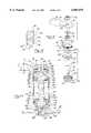
- FIG. 1shows a conventional or prior art end link which is similar in construction to that shown in U.S. Pat. No. 4,875,703 to Murakami.
- end link 10is composed of a bolt 12 onto which is placed a first washer 14a and a first rubber bushing 16a.
- Bolt 12is then passed through a hole 18 provided in a flattened end 20 of an arm segment 22 of a stabilizer bar 24.
- a second rubber bushing 16b and second washer 14bare placed over bolt 12 as shown.
- a rigid cylindrical spacer 26is placed over bolt 12 as are a third washer 14c and a third bushing 16c.
- Bolt 12then passes through a bore 28 formed in a control arm of the suspension system which, in the present example, is a bracket 30 attached to or integrally formed as part of an upper control arm 32.
- a fourth rubber bushing 16d and a fourth washer 14dare then placed over bolt 12 and a nut 34 is fastened to the end of bolt 12 to secure the assembly together.
- Rubber bushings 14a through 14dare provided to allow control arm 30 and arm segment 22 of stabilizer bar 24 to pivot relative to one another as the suspension travels through its range of motion. This pivoting action, typically referred to as angularity, is caused by the fact that control arm 30 pivots in a plane which is substantially perpendicular to the plane through which arm segment 22 of stabilizer bar 24 pivots.
- the rubber bushingswhile necessary to allow for angularity, reduce the initial effectiveness of the stabilizer bar.
- the stabilizer bardoes not begin to experience torsional forces and act to correct the roll condition of the vehicle until the rubber bushings have been substantially compressed and, in affect, have become solid members.
- This initial lack of stabilizing actionallows the vehicle to gain momentum in the roll direction.
- This momentummust be overcome by the torsional forces of the stabilizer bar in addition to the forces which are imparted by the cornering action.
- this initial "softness" in roll rigidityoften gives the driver a perception that the vehicle is not properly responding to the steering input.
- various shapes and stiffness for the rubber bushingshave been developed over the years to minimize this affect, a limiting design constraint is that the system must remain pliable enough to accommodate the angularity between the stabilizer bar and the suspension control arm.
- the present inventionprovides a suspension assembly including a pair of end links which interconnect the opposite ends of a stabilizer bar to a pair of suspension members.
- the stabilizer barhas a central segment and arm segments extending from each end of the central segment.
- the end linksinterconnect the distal ends of the arm segments to the suspension members.
- Each end linkincludes a pair of ball and socket assemblies which are connected to one another at a first end and are connected to the stabilizer bar and the suspension member at the other end.
- the ball and socket assembliesprovide for and accommodate angularity between the stabilizer bar and the suspension member as the suspension travels through its range of motion while also eliminating or reducing the amount of compliance that is experienced before the stabilizer bar begins to urge the suspension member its normal position during vehicle maneuvers.
- the end linkscan be assembled from a common set of components for use in a variety of different suspension applications to accommodate different length requirements.
- this modular arrangementpermits end links assembled from such a common set of components to be used in both original equipment and replacement part applications.
- FIG. 1is a sectional view of an exemplary prior art end link
- FIG. 2is a perspective view of an exemplary independent front wheel suspension system into which the present invention is incorporated;
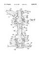
- FIG. 3is a sectional view of a portion of the suspension system shown in FIG. 2 and which illustrates an end link made in accordance with one preferred embodiment of the present invention
- FIG. 4is a partial exploded perspective view of the end link shown in FIG. 3;
- FIG. 5is a partial section view showing a modified version of the end link shown in FIG. 3;
- FIG. 6is a sectional view of a portion of the suspension system shown in FIG. 2 and which illustrates an end link made in accordance with another preferred embodiment of the present invention
- FIG. 7is a partial exploded perspective view of the end link shown in FIG. 6;
- FIG. 8is a sectional view of a portion of the suspension system shown in FIG. 2 illustrating an end link made in accordance with yet another embodiment of the present invention.
- the present inventionis directed to an end link for connecting a stabilizer bar to a suspension member, such as a control arm, in a vehicle suspension.
- the end link of the present inventionis adapted to replace most conventional end links and to provide improved performance without requiring modification of the other components associated with the vehicle suspension.
- the end link of the present inventionmay be utilized with a wide variety of suspension systems and is not intended to be limited to the particular application described herein.
- FIG. 2shows an independent front wheel suspension system, generally indicated at 50, of the type having upper and lower control arms and a strut assembly at each wheel which are suspended from the vehicle frame.
- frame 52is shown to partially include a pair of longitudinal side rails 54 and a crossbeam 56.
- Suspension system 50includes a long lower control arm 58 and a short supper control arm 60 which are both pivotally attached to frame 52.
- a strut assembly having a helical coil spring 62 and a strut damper 64is retained between an intermediate portion of lower control arm 58 and frame 52 to support the weight of the vehicle and any loads which are transmitted through lower control arm 58.
- Upper control arm 60is connected to lower control arm 58 by a steering knuckle 66.
- a hub and rotor assembly 68is rotatably attached to a spindle portion (not shown) of steering knuckle 66 such that a wheel and tire (also not shown) may be mounted thereon.
- a stabilizer bar 70is shown to include an elongated central segment 72 which extends laterally across the vehicle, and a pair of arm segments 74 which extend longitudinally along the vehicle at each end of central segment 72.
- Central segment 72is rotatably attached to frame rails 54 by a pair of mounting brackets 76.
- a distal end 78 of each arm segment 74is connected to a corresponding lower control arm 58 by an end link 80 made in accordance with the teachings of the present invention.
- end link 80is shown fastened to stabilizer bar 70 at one end and to lower control arm 58 at its opposite end.
- the embodiment shownis symmetrical about a horizontal plane, identified by construction line "A".
- end link 80is assembled from a set of components including two ball and socket assemblies 82 and 82' which are rigidly interconnected by suitable means such as, for example, a weld, as shown along weld line 84. Due to the similarity of the components associated with ball and socket assembly 82' with respect to the components of ball and socket assembly 82, its components are identified with the same reference numerals but having a primed designation.
- Ball and socket assembly 82includes a hollow cylindrical housing 86 having an upstanding threaded post 88, a disc portion 90 and an annular wall 92 projecting generally perpendicular from disc portion 90 so as to define a socket cavity 94.
- Ball and socket assembly 82also includes a ball stud 96 having a shank segment 98 and a ball segment 100 which is retained in cavity 94 between a spring seat 102 and a ball seat 104.
- Spring seat 102is shown inserted into a reduced diameter portion 106 of cavity 94 with a belleville spring washer 108 positioned between a planar end face 110 of housing disc portion 90 and a planar end face 112 of spring seat 102.
- a partial spherical seat surface 114extends inwardly from the opposite planar end face 116 of spring seat 102 when assembled.
- Seat surface 114is adapted to engage a portion of the spherical external surface of ball segment 100.
- its shank segment 98Prior to assembly of ball stud 96 into housing 86, its shank segment 98 is passed through a bore 118 formed through ball seat 104 such that another portion of the spherical exterior surface of ball segment 100 engages a partial spherical seat surface 120 formed in ball seat 104 and which communicates with bore 118.
- external threads 122 formed on ball seat 104are threaded into internal threads 124 formed in cavity 94 of housing 86.
- Ball seat 104is tightened into housing 86 until a desired torque is reached. Thereafter, a distal end of ball seat 104 is inwardly swaged or crimped to create an inward lip flange 126 for preventing ball seat 98 from unthreading itself during use. As an alternative, a welded joint may be used in place of lip flange 126. As a further alternative, ball seat 104 need not be threaded to housing 86 but instead may be retained therein simply by crimping of the distal end to again create lip flange 126.
- shank segment 98 of ball stud 96is connected to shank segment 98' of ball stud 96' along joint line 84 by welding or other methods for rigidly fixing ball and socket assemblies 82 and 82' together. Any typical methods of welding, including friction welding or laser welding, are within the contemplated scope of this invention.
- FIG. 5partially illustrates shank segments 98 and 98' as having external threads 126 and 126', respectively, formed thereon which are threaded into internal threads 128 of a threaded collar or connector 130. Such a threaded connection permits the overall length of end link 80 to be varied such that end link 80 can be used in a variety of different suspension applications.
- a flexible tubular seal 132is slipped over ball and socket assemblies 82 and 82' with its ends secured to housings 86 and 86' in a suitable manner, such as by clamp rings 134 and 134'.
- end link 80is adapted for connection between control arm 58 and stabilizer bar 70.
- a bore 136is formed in end portion 78 of each arm segment 74 of stabilizer bar 70 while a corresponding bore 138 is formed in each lower control arm 58.
- a washer 140is mounted on threaded post 88 of housing 86 which is then inserted through bore 136 in arm segment 78.
- a suitable fastenersuch as lock nut 142, is threaded onto threaded post 88 and tightened to a suitable torque level.
- a washer 140'is mounted on threaded post 88' of housing 86' which is then inserted through bore 138 in control arm 58.
- a lock nut 142'is then tightened onto threaded post 88' to a suitable torque level.
- each end link 80is secured between an arm segment 74 of stabilizer bar 70 and one a lower control arm 58.
- end link 180is shown in FIGS. 6 and 7 wherein similar components thereof are identified by like reference numbers used to describe end link 80.
- the component of end link 180are substantially similar to those of end link 80 with the exception that shank segments 98, 98' are now shown to include external threads 126, 126' in a manner similar to that shown in FIG. 5.
- end link 180includes a pair of ball and socket assemblies 82 and 82' which are joined together by threaded connector 130 securing threaded post 88 on housing 86 to threaded post 88' on housings 86'.
- Threaded connector 130can be provided in varying lengths thereby allowing end link 180 to be assembled at various overall lengths for use in retrofit applications into existing vehicle suspensions originally equipped with prior art type end links and/or to allow flexibility of design for the suspension engineer. While threaded connector 130 is shown to threadingly engage posts 88 and 88', connector 130 could also be welded thereto, with or without threads, or joined in another method now known or later developed, without deviating from the spirit of the present invention.
- End link 180is secured between stabilizer bar 70 and control arm 58 by inserting threaded portion 126 of shank segment 98 through bore 136 in end 78 of arm segment 74 and securely threading locking nut 142 thereon.
- washer 140is retained between a shoulder 148 formed on shank segment 98 and end 78 of arm segment 74, with washer 140 providing a larger clamping surface to minimize angular tipping of ball stud 96 relative to end 78 of arm segment 74.
- shank segment 98'has washer 140 mounted thereon against shoulder 148' and which is then inserted through bore 138 in control arm 58. Lock nut 142' is tightened onto threaded portion 126' of ball stud 96'.
- a flexible seal 150is also provided which is attached between housing 86 and ball stud 96 using clamp rings 152 and 154. Seal 150 prevents water and contaminants from entering ball and socket assembly 76 and hindering the smooth operation thereof.
- end link 280made in accordance with yet another embodiment of the present invention is shown.
- end link 280is assembled from ball and socket assemblies 82 and 82' which are oriented and interconnected in an arrangement differing from that shown in FIGS. 3 and 6.
- end link 280is shown to have threaded section 126 of ball stud 96 mounted to end 78 of arm segment 74 on stabilizer bar 70 while threaded post 88' on housing 86' is mounted to control arm 58.
- threaded connector 130interconnects threaded post 88 of housing 86 to threaded section 126' of ball stud 96', thereby rigidly interconnecting ball and socket assembly 82 to ball and socket assembly 82'.
- the arrangement shown in FIG. 8could be modified such that end link 280 is reversed in its orientation with threaded post 88' secured to stabilizer bar 70 and threaded segment 126 secured to control arm 58.
- each end link of the present inventionutilizes the pair of interconnected ball and socket assemblies 82 and 82' to allow for the angularity introduced into the suspension.
- One advantage of these end linksis that there is virtually no initial compliance of the type inherently associated with the rubber bushing used in the prior art.
- the present inventionis designed such that there is minimal axial tolerance, the only axial compliance being that of belleville springs 108 and 108' inserted respectively between housing 86 and 86' and spring seat 102 and 102'. Belleville springs 108 and 108' acts to remove lash from the system and provide for wear compensation.
- end links 80, 180 and 280provide a more direct and instantaneous communication of movement between control arm 58 to stabilizer bar 70.
- This improved communicationduring cornering maneuvers the vehicle is not allowed an initial period of lateral body roll before stabilizer bar 70 begins to urge each control arm 58 toward its normal position.
- the effect of this direct communicationis characterized as the vehicle driver having a crisper or more responsive tactile feeling of control with the perception of improved response to the steering input.
- Lubricationcan be provided to assemblies 82 and 82' to minimize wear and encourage smooth operation.
- a grease fitting(not shown) can be fastened to an axial passage 144 formed in threaded post 88 or the end link 80 be of a sealed "lubricated for life" type wherein lubrication is deposited prior to assembly of the components.
- a bore 146 in spring seat 102permits lubrication to communicate with ball segment 100 and mating spherical surfaces 114 and 120.
- axial passage 144could instead be provided through ball stud 96 or wall 92 of housing.
- end link 80is well-suited for systems with tight packaging requirements since the distance between ball segments 100 and 100' can typically be greater for a given overall length.
- end links using connector 130have the advantage of permitting adjustment to the overall length.
- any of the systems disclosed hereinwork well individually with a given suspension system but one may be favorable over the other because of a great number of factors, including but not limited to those mentioned above.
- the end links constructed according to any embodiment of the present inventioncan be used in vehicular suspension systems to connect stabilizer bar 70 to any desired suspension member instead of control arm 58 if the application dictates such an arrangement.
- ball and socket assemblies 82 and 82'are described and illustrated as being generally identical to one another, it is contemplated by the inventors that the pair of ball and socket assemblies interconnected to form an end link may differ from one another as to dimensional sizes, shapes, and other design factors which do not hinder the coordinated function and connection therebetween.
Landscapes
- Engineering & Computer Science (AREA)
- Mechanical Engineering (AREA)
- Vehicle Body Suspensions (AREA)
Abstract
Description
Claims (21)
Priority Applications (5)
| Application Number | Priority Date | Filing Date | Title |
|---|---|---|---|
| US08/863,810US6007079A (en) | 1997-02-14 | 1997-05-27 | Direct acting end link for stabilizer bar |
| MX9801112AMX9801112A (en) | 1997-02-14 | 1998-02-10 | Direct acting end link for stabilizer bar. |
| CA 2229194CA2229194A1 (en) | 1997-02-14 | 1998-02-10 | Direct acting end link for stabilizer bar |
| DE19805810ADE19805810B4 (en) | 1997-02-14 | 1998-02-12 | Connection element for a torsion stabilizer |
| BR9800608ABR9800608A (en) | 1997-02-14 | 1998-02-13 | Directly activated end joint for stabilizer bar |
Applications Claiming Priority (2)
| Application Number | Priority Date | Filing Date | Title |
|---|---|---|---|
| US3877097P | 1997-02-14 | 1997-02-14 | |
| US08/863,810US6007079A (en) | 1997-02-14 | 1997-05-27 | Direct acting end link for stabilizer bar |
Publications (1)
| Publication Number | Publication Date |
|---|---|
| US6007079Atrue US6007079A (en) | 1999-12-28 |
Family
ID=26715528
Family Applications (1)
| Application Number | Title | Priority Date | Filing Date |
|---|---|---|---|
| US08/863,810Expired - LifetimeUS6007079A (en) | 1997-02-14 | 1997-05-27 | Direct acting end link for stabilizer bar |
Country Status (4)
| Country | Link |
|---|---|
| US (1) | US6007079A (en) |
| BR (1) | BR9800608A (en) |
| DE (1) | DE19805810B4 (en) |
| MX (1) | MX9801112A (en) |
Cited By (29)
| Publication number | Priority date | Publication date | Assignee | Title |
|---|---|---|---|---|
| US6209897B1 (en)* | 1999-07-15 | 2001-04-03 | Paccar Inc | Apparatus and method for mounting a suspension system |
| WO2002006066A1 (en)* | 2000-07-18 | 2002-01-24 | Maclean-Fogg Company | Link assembly for automotive suspension system |
| US6412797B1 (en)* | 1999-11-09 | 2002-07-02 | Hyundai Motor Company | Front wheel suspension system for a vehicle |
| US6435527B1 (en)* | 1999-09-30 | 2002-08-20 | Kabushiki Kaisha Toyoda Jidoshokki Seisakusho | Mechanism for adjusting toe angle of wheel and steering apparatus |
| US20030086756A1 (en)* | 2001-11-07 | 2003-05-08 | Trotter Jason K | Modular linkage system |
| US6572127B2 (en) | 2001-05-18 | 2003-06-03 | Maclean-Fogg Company | Link assembly for a vehicle suspension system |
| US20030111817A1 (en)* | 2001-12-19 | 2003-06-19 | Joseph Fader | Band for anti-lateral movement of stabilizer bar |
| US6604270B2 (en)* | 2000-12-14 | 2003-08-12 | American Axle & Manufacturing, Inc. | Robust, low mass stabilizer bar link assembly |
| US20030214110A1 (en)* | 2002-05-16 | 2003-11-20 | Andre Diener | Two-joint arrangement |
| WO2004000585A1 (en)* | 2002-06-25 | 2003-12-31 | ZF Lemförder Metallwaren AG | Pendulum support consisting of an extruded profile |
| WO2004005055A1 (en)* | 2002-07-09 | 2004-01-15 | ZF Lemförder Metallwaren AG | Articulated support with integrated balljoint |
| US20040037621A1 (en)* | 2000-11-24 | 2004-02-26 | Yoshihiro Suzuki | Ball joint |
| US20040155427A1 (en)* | 2003-02-10 | 2004-08-12 | Honda Motor Co., Ltd. | Supporting structure of stabilizer to vehicle body |
| US20040258463A1 (en)* | 1999-08-16 | 2004-12-23 | Trw Fahrwerksysteme Gmbh & Co. Kg | Ball-and-socket joint with bearing shell |
| US20050035566A1 (en)* | 2003-08-14 | 2005-02-17 | Visteon Global Technologies, Inc. | Stabilizer bar integrated end link |
| US6875388B2 (en) | 2001-11-07 | 2005-04-05 | Illinois Tool Works Inc. | Method for making a ball and socket joint |
| US20050079032A1 (en)* | 2001-05-18 | 2005-04-14 | Jiri Pazdirek | Link assembly for a vehicle suspension system |
| US6929271B2 (en) | 2001-11-09 | 2005-08-16 | Illinois Tool Works Inc. | Hydraulically compensated stabilizer system |
| US20050276656A1 (en)* | 2004-06-04 | 2005-12-15 | Lim Chong K | Joint assembly |
| US20060254784A1 (en)* | 2003-09-08 | 2006-11-16 | Stephan Hartmann | Longitudinal support |
| US7465135B2 (en) | 2003-11-14 | 2008-12-16 | Maclean-Fogg Company | U-Nut fastening assembly |
| KR100877637B1 (en)* | 2002-06-25 | 2009-01-12 | 젯에프 렘푀르더 게엠베하 | Extrusion molding shake column and its manufacturing method |
| US7887072B2 (en) | 2008-10-09 | 2011-02-15 | American Axle & Manufacturing, Inc. | Stabilizer bar with disconnectable link |
| US8011866B2 (en) | 2001-08-20 | 2011-09-06 | Maclean-Fogg Company | Locking fastener assembly |
| US20150014954A1 (en)* | 2013-07-15 | 2015-01-15 | Ford Global Technologies, Llc | Method and device for stabilizing a vehicle against rolling movements |
| US20170129301A1 (en)* | 2015-11-10 | 2017-05-11 | Federal-Mogul Motorparts Corporation | Sway Bar Linkage With Bushing |
| FR3072903A1 (en)* | 2017-11-02 | 2019-05-03 | Psa Automobiles Sa | CONNECTING ROD SYSTEM WITH MODULAR FLEXIBILITY OF ANTI-DEVERS BAR |
| US11608854B2 (en) | 2017-08-16 | 2023-03-21 | Multimatic Inc. | Ball joint with injection molded bearing |
| US11773897B1 (en)* | 2023-01-26 | 2023-10-03 | Super ATV, LLC | Ball joint |
Families Citing this family (3)
| Publication number | Priority date | Publication date | Assignee | Title |
|---|---|---|---|---|
| US5954353A (en)* | 1998-02-06 | 1999-09-21 | American Axle & Manufacturing, Inc. | Plug in direct acting stabilizer bar link |
| DE102006055565B3 (en) | 2006-11-24 | 2008-02-21 | Ford Global Technologies, LLC, Dearborn | Wheel suspension for motor vehicle, has transverse link and wheel carrier, where wheel carrier has linking element traversed by bolt for connection with transverse link |
| JP6019080B2 (en)* | 2014-09-26 | 2016-11-02 | 富士重工業株式会社 | Connecting structure for vehicle underbody members |
Citations (10)
| Publication number | Priority date | Publication date | Assignee | Title |
|---|---|---|---|---|
| US3549167A (en)* | 1967-05-26 | 1970-12-22 | Daimler Benz Ag | Joint connection for the suspension of steerable wheels of a motor vehicle |
| US4875703A (en)* | 1986-12-16 | 1989-10-24 | Nissan Motor Co., Ltd. | Double link type suspension including a stabilizer bar |
| US4944523A (en)* | 1989-03-03 | 1990-07-31 | Illinois Tool Works | End link for stabilizer bar |
| US5102160A (en)* | 1990-11-28 | 1992-04-07 | General Motors Corporation | Connector assembly for a stabilizer bar |
| US5112031A (en)* | 1990-08-27 | 1992-05-12 | General Motors Corporation | Interlocking mounting bushing assembly for a stabilizer bar |
| US5165306A (en)* | 1990-10-04 | 1992-11-24 | Maclean-Fogg Company | Vehicle stabilizer bar end link |
| US5186486A (en)* | 1991-07-19 | 1993-02-16 | General Motors Corporation | Active link for a stabilizer bar |
| US5352059A (en)* | 1991-02-14 | 1994-10-04 | Musashi Seimitsu Kogyo Company Ltd. | Synthetic resin ball joint with reinforcing rib |
| US5449193A (en)* | 1993-07-27 | 1995-09-12 | Illinois Tool Works Inc. | End link for a vehicle stabilizer bar |
| US5551722A (en)* | 1988-10-26 | 1996-09-03 | Maclean-Fogg Company | Vehicle suspension link |
Family Cites Families (3)
| Publication number | Priority date | Publication date | Assignee | Title |
|---|---|---|---|---|
| DE2742837A1 (en)* | 1977-09-23 | 1979-03-29 | Ehrenreich Gmbh & Co Kg A | AXIAL BALL JOINT |
| US5368326A (en)* | 1993-07-01 | 1994-11-29 | Ford Motor Company | Apparatus for insuring neutral stabilizer bar installation |
| DE19504086A1 (en)* | 1995-02-08 | 1996-08-14 | Trw Fahrwerksyst Gmbh & Co | Landing gear strut |
- 1997
- 1997-05-27USUS08/863,810patent/US6007079A/ennot_activeExpired - Lifetime
- 1998
- 1998-02-10MXMX9801112Apatent/MX9801112A/ennot_activeIP Right Cessation
- 1998-02-12DEDE19805810Apatent/DE19805810B4/ennot_activeExpired - Fee Related
- 1998-02-13BRBR9800608Apatent/BR9800608A/ennot_activeIP Right Cessation
Patent Citations (10)
| Publication number | Priority date | Publication date | Assignee | Title |
|---|---|---|---|---|
| US3549167A (en)* | 1967-05-26 | 1970-12-22 | Daimler Benz Ag | Joint connection for the suspension of steerable wheels of a motor vehicle |
| US4875703A (en)* | 1986-12-16 | 1989-10-24 | Nissan Motor Co., Ltd. | Double link type suspension including a stabilizer bar |
| US5551722A (en)* | 1988-10-26 | 1996-09-03 | Maclean-Fogg Company | Vehicle suspension link |
| US4944523A (en)* | 1989-03-03 | 1990-07-31 | Illinois Tool Works | End link for stabilizer bar |
| US5112031A (en)* | 1990-08-27 | 1992-05-12 | General Motors Corporation | Interlocking mounting bushing assembly for a stabilizer bar |
| US5165306A (en)* | 1990-10-04 | 1992-11-24 | Maclean-Fogg Company | Vehicle stabilizer bar end link |
| US5102160A (en)* | 1990-11-28 | 1992-04-07 | General Motors Corporation | Connector assembly for a stabilizer bar |
| US5352059A (en)* | 1991-02-14 | 1994-10-04 | Musashi Seimitsu Kogyo Company Ltd. | Synthetic resin ball joint with reinforcing rib |
| US5186486A (en)* | 1991-07-19 | 1993-02-16 | General Motors Corporation | Active link for a stabilizer bar |
| US5449193A (en)* | 1993-07-27 | 1995-09-12 | Illinois Tool Works Inc. | End link for a vehicle stabilizer bar |
Cited By (48)
| Publication number | Priority date | Publication date | Assignee | Title |
|---|---|---|---|---|
| US6209897B1 (en)* | 1999-07-15 | 2001-04-03 | Paccar Inc | Apparatus and method for mounting a suspension system |
| US20040258463A1 (en)* | 1999-08-16 | 2004-12-23 | Trw Fahrwerksysteme Gmbh & Co. Kg | Ball-and-socket joint with bearing shell |
| US6840697B1 (en)* | 1999-08-16 | 2005-01-11 | Trw Fahrwerksysteme Gmbh & Co. Kg | Ball-and-socket joint with bearing shell |
| US6435527B1 (en)* | 1999-09-30 | 2002-08-20 | Kabushiki Kaisha Toyoda Jidoshokki Seisakusho | Mechanism for adjusting toe angle of wheel and steering apparatus |
| US6412797B1 (en)* | 1999-11-09 | 2002-07-02 | Hyundai Motor Company | Front wheel suspension system for a vehicle |
| WO2002006066A1 (en)* | 2000-07-18 | 2002-01-24 | Maclean-Fogg Company | Link assembly for automotive suspension system |
| US6402171B1 (en)* | 2000-07-18 | 2002-06-11 | Maclean-Fogg Company | Link assembly for automotive suspension system |
| US20040037621A1 (en)* | 2000-11-24 | 2004-02-26 | Yoshihiro Suzuki | Ball joint |
| US6604270B2 (en)* | 2000-12-14 | 2003-08-12 | American Axle & Manufacturing, Inc. | Robust, low mass stabilizer bar link assembly |
| US7354054B2 (en) | 2001-05-18 | 2008-04-08 | Maclean-Fogg Company | Link assembly for a vehicle suspension system |
| US20080054583A1 (en)* | 2001-05-18 | 2008-03-06 | Jiri Pazdirek | Link assembly for a vehicle suspension system |
| US20030127818A1 (en)* | 2001-05-18 | 2003-07-10 | Jiri Pazdirek | Link assembly for a vehicle suspension system |
| US6572127B2 (en) | 2001-05-18 | 2003-06-03 | Maclean-Fogg Company | Link assembly for a vehicle suspension system |
| US20050079032A1 (en)* | 2001-05-18 | 2005-04-14 | Jiri Pazdirek | Link assembly for a vehicle suspension system |
| US8011866B2 (en) | 2001-08-20 | 2011-09-06 | Maclean-Fogg Company | Locking fastener assembly |
| US20030086756A1 (en)* | 2001-11-07 | 2003-05-08 | Trotter Jason K | Modular linkage system |
| US20050123345A1 (en)* | 2001-11-07 | 2005-06-09 | Trotter Jason K. | Method and apparatus for making a ball and socket joint and joint made by same |
| US6875388B2 (en) | 2001-11-07 | 2005-04-05 | Illinois Tool Works Inc. | Method for making a ball and socket joint |
| US6929271B2 (en) | 2001-11-09 | 2005-08-16 | Illinois Tool Works Inc. | Hydraulically compensated stabilizer system |
| US20030111817A1 (en)* | 2001-12-19 | 2003-06-19 | Joseph Fader | Band for anti-lateral movement of stabilizer bar |
| US6733019B2 (en)* | 2002-05-16 | 2004-05-11 | ZF Lemförder Metallwaren AG | Two-joint arrangement |
| US20030214110A1 (en)* | 2002-05-16 | 2003-11-20 | Andre Diener | Two-joint arrangement |
| US7478968B2 (en) | 2002-06-25 | 2009-01-20 | ZF Lemförder Metallwaren AG | Rocker pendulum made of an extruded section |
| KR100877637B1 (en)* | 2002-06-25 | 2009-01-12 | 젯에프 렘푀르더 게엠베하 | Extrusion molding shake column and its manufacturing method |
| US20040262873A1 (en)* | 2002-06-25 | 2004-12-30 | Zf Lemforder Metallwaren Ag. | Rocker pendulum made of an extruded section |
| WO2004000585A1 (en)* | 2002-06-25 | 2003-12-31 | ZF Lemförder Metallwaren AG | Pendulum support consisting of an extruded profile |
| US20040258461A1 (en)* | 2002-07-09 | 2004-12-23 | Zf Lemforder Metallwaren Ag | Rocker pendulum with integrated ball and socket joint |
| CN100448706C (en)* | 2002-07-09 | 2009-01-07 | Zf雷姆伏尔德金属制品股份公司 | Pendulum bearing with integrated ball and socket joint |
| US7331733B2 (en) | 2002-07-09 | 2008-02-19 | Zf Lemforder Metallwaren Ag | Rocker pendulum with integrated ball and socket joint |
| WO2004005055A1 (en)* | 2002-07-09 | 2004-01-15 | ZF Lemförder Metallwaren AG | Articulated support with integrated balljoint |
| US7624999B2 (en) | 2003-02-10 | 2009-12-01 | Honda Motor Co., Ltd. | Supporting structure of stabilizer to vehicle body |
| US7419173B2 (en)* | 2003-02-10 | 2008-09-02 | Honda Motor Co., Ltd. | Supporting structure of stabilizer to vehicle body |
| US20080211201A1 (en)* | 2003-02-10 | 2008-09-04 | Kiyoshi Nakajima | Supporting structure of stabilizer to vehicle body |
| US20040155427A1 (en)* | 2003-02-10 | 2004-08-12 | Honda Motor Co., Ltd. | Supporting structure of stabilizer to vehicle body |
| US20050035566A1 (en)* | 2003-08-14 | 2005-02-17 | Visteon Global Technologies, Inc. | Stabilizer bar integrated end link |
| US7178815B2 (en) | 2003-08-14 | 2007-02-20 | Automotive Components Holdings, Llc | Stabilizer bar integrated end link |
| US20060254784A1 (en)* | 2003-09-08 | 2006-11-16 | Stephan Hartmann | Longitudinal support |
| US7465135B2 (en) | 2003-11-14 | 2008-12-16 | Maclean-Fogg Company | U-Nut fastening assembly |
| US20050276656A1 (en)* | 2004-06-04 | 2005-12-15 | Lim Chong K | Joint assembly |
| US7887072B2 (en) | 2008-10-09 | 2011-02-15 | American Axle & Manufacturing, Inc. | Stabilizer bar with disconnectable link |
| US20150014954A1 (en)* | 2013-07-15 | 2015-01-15 | Ford Global Technologies, Llc | Method and device for stabilizing a vehicle against rolling movements |
| US9517676B2 (en)* | 2013-07-15 | 2016-12-13 | Ford Global Technologies, Llc | Method and device for stabilizing a vehicle against rolling movements |
| US20170129301A1 (en)* | 2015-11-10 | 2017-05-11 | Federal-Mogul Motorparts Corporation | Sway Bar Linkage With Bushing |
| US10017026B2 (en)* | 2015-11-10 | 2018-07-10 | Federal-Mogul Motorparts Llc | Sway bar linkage with bushing |
| US11608854B2 (en) | 2017-08-16 | 2023-03-21 | Multimatic Inc. | Ball joint with injection molded bearing |
| US11649852B2 (en) | 2017-08-16 | 2023-05-16 | Multimatic Inc. | Ball joint with injection molded bearing |
| FR3072903A1 (en)* | 2017-11-02 | 2019-05-03 | Psa Automobiles Sa | CONNECTING ROD SYSTEM WITH MODULAR FLEXIBILITY OF ANTI-DEVERS BAR |
| US11773897B1 (en)* | 2023-01-26 | 2023-10-03 | Super ATV, LLC | Ball joint |
Also Published As
| Publication number | Publication date |
|---|---|
| MX9801112A (en) | 1998-11-30 |
| BR9800608A (en) | 1999-06-01 |
| DE19805810B4 (en) | 2004-09-09 |
| DE19805810A1 (en) | 1998-08-20 |
Similar Documents
| Publication | Publication Date | Title |
|---|---|---|
| US6007079A (en) | Direct acting end link for stabilizer bar | |
| US5954353A (en) | Plug in direct acting stabilizer bar link | |
| EP0479598B1 (en) | Vehicle stabilizer bar end link | |
| US6076840A (en) | Self-locking plug-in stabilizer bar links | |
| US6254114B1 (en) | Composite stabilizer bar link | |
| EP1051304B1 (en) | Suspension link assembly | |
| JP4119263B2 (en) | Link assembly for automobile suspension system | |
| EP1286845B1 (en) | Self-locking plug-in stabilizer bar link mechanism | |
| EP0770506B1 (en) | Improvements in and relating to anti-roll bar assemblies for road vehicles | |
| MXPA04006583A (en) | Control rod suspension with outboard shock. | |
| EP1065077A1 (en) | Plug in direct acting stabilizer bar link | |
| US6648350B1 (en) | Suspension system for a vehicle having a vehicle stabilizer bar with integral end links | |
| CA2229194A1 (en) | Direct acting end link for stabilizer bar | |
| KR102215230B1 (en) | Torsion Beam Axle Type Rear Suspension System For Vehicle | |
| KR102063351B1 (en) | Vibration-damping device for vehicles | |
| MXPA99001315A (en) | Coupling of stabilizing bar of direct action, plug | |
| JP2010126139A (en) | Structure for fastening suspension arm | |
| KR20080023911A (en) | Coupling Structure of Lower Arm Assembly and Ball Joint Assembly for Automotive | |
| KR0118617Y1 (en) | Automotive Stabilizer Control Link Structure | |
| KR200149034Y1 (en) | Strut Mount Bushing for Independent Suspension of Automobile | |
| KR200173939Y1 (en) | Lower arm assembly structure for automobile suspension | |
| KR100201471B1 (en) | Independence suspension for vehicle | |
| KR20040003197A (en) | Mounting structure for stabilizer bar | |
| MXPA99010268A (en) | Compu stabilizing bar joint | |
| KR20030014798A (en) | mounting structure of strut assembly for vehicle |
Legal Events
| Date | Code | Title | Description |
|---|---|---|---|
| AS | Assignment | Owner name:AMERICAN AXLE & MANUFACTURING INC., MICHIGAN Free format text:ASSIGNMENT OF ASSIGNORS INTEREST;ASSIGNORS:KINCAID, JEFFREY L.;HARVEY, TALON T.;WASYLEWSKI, NEIL A.;REEL/FRAME:008747/0608;SIGNING DATES FROM 19970808 TO 19970829 | |
| STCF | Information on status: patent grant | Free format text:PATENTED CASE | |
| AS | Assignment | Owner name:CHASE MANHATTAN BANK, AS COLLATERAL AGENT, THE, NE Free format text:SUPPLEMENT TO INTELLECTUAL PROPERTY SECURITY AGREE;ASSIGNORS:AMERICAN AXLE & MANUFACTURING, INC.;MSP INDUSTRIES CORPORATION;COLFOR MANUFACTURING, INC.;REEL/FRAME:012177/0112 Effective date:20010815 | |
| CC | Certificate of correction | ||
| FPAY | Fee payment | Year of fee payment:4 | |
| AS | Assignment | Owner name:AMERICAN AXLE & MANUFACTURING, INC., MICHIGAN Free format text:SECURITY AGREEMENT RELEASE;ASSIGNOR:JPMORGAN CHASE BANK;REEL/FRAME:014926/0190 Effective date:20040116 | |
| FPAY | Fee payment | Year of fee payment:8 | |
| FPAY | Fee payment | Year of fee payment:12 | |
| AS | Assignment | Owner name:JPMORGAN CHASE BANK, N.A., AS COLLATERAL AGENT, NE Free format text:SECURITY INTEREST;ASSIGNORS:AMERICAN AXLE & MANUFACTURING, INC.;CLOYES GEAR AND PRODUCTS, INC.;GREDE LLC;AND OTHERS;REEL/FRAME:042734/0001 Effective date:20170605 Owner name:JPMORGAN CHASE BANK, N.A., AS COLLATERAL AGENT, NEW YORK Free format text:SECURITY INTEREST;ASSIGNORS:AMERICAN AXLE & MANUFACTURING, INC.;CLOYES GEAR AND PRODUCTS, INC.;GREDE LLC;AND OTHERS;REEL/FRAME:042734/0001 Effective date:20170605 |