US6007036A - Stowable support apparatus - Google Patents
Stowable support apparatusDownload PDFInfo
- Publication number
- US6007036A US6007036AUS08/936,027US93602797AUS6007036AUS 6007036 AUS6007036 AUS 6007036AUS 93602797 AUS93602797 AUS 93602797AUS 6007036 AUS6007036 AUS 6007036A
- Authority
- US
- United States
- Prior art keywords
- slide
- track
- display unit
- lock mechanism
- mounting bracket
- Prior art date
- Legal status (The legal status is an assumption and is not a legal conclusion. Google has not performed a legal analysis and makes no representation as to the accuracy of the status listed.)
- Expired - Lifetime
Links
Images


Classifications
- B—PERFORMING OPERATIONS; TRANSPORTING
- B64—AIRCRAFT; AVIATION; COSMONAUTICS
- B64D—EQUIPMENT FOR FITTING IN OR TO AIRCRAFT; FLIGHT SUITS; PARACHUTES; ARRANGEMENT OR MOUNTING OF POWER PLANTS OR PROPULSION TRANSMISSIONS IN AIRCRAFT
- B64D11/00—Passenger or crew accommodation; Flight-deck installations not otherwise provided for
- B64D11/0015—Arrangements for entertainment or communications, e.g. radio, television
- B64D11/00153—Monitors mounted on or in the seat other than the seat back
- B—PERFORMING OPERATIONS; TRANSPORTING
- B60—VEHICLES IN GENERAL
- B60R—VEHICLES, VEHICLE FITTINGS, OR VEHICLE PARTS, NOT OTHERWISE PROVIDED FOR
- B60R11/00—Arrangements for holding or mounting articles, not otherwise provided for
- B60R11/02—Arrangements for holding or mounting articles, not otherwise provided for for radio sets, television sets, telephones, or the like; Arrangement of controls thereof
- B60R11/0229—Arrangements for holding or mounting articles, not otherwise provided for for radio sets, television sets, telephones, or the like; Arrangement of controls thereof for displays, e.g. cathodic tubes
- B60R11/0235—Arrangements for holding or mounting articles, not otherwise provided for for radio sets, television sets, telephones, or the like; Arrangement of controls thereof for displays, e.g. cathodic tubes of flat type, e.g. LCD
- B—PERFORMING OPERATIONS; TRANSPORTING
- B64—AIRCRAFT; AVIATION; COSMONAUTICS
- B64D—EQUIPMENT FOR FITTING IN OR TO AIRCRAFT; FLIGHT SUITS; PARACHUTES; ARRANGEMENT OR MOUNTING OF POWER PLANTS OR PROPULSION TRANSMISSIONS IN AIRCRAFT
- B64D11/00—Passenger or crew accommodation; Flight-deck installations not otherwise provided for
- B64D11/06—Arrangements of seats, or adaptations or details specially adapted for aircraft seats
- B64D11/0627—Seats combined with storage means
- B—PERFORMING OPERATIONS; TRANSPORTING
- B60—VEHICLES IN GENERAL
- B60R—VEHICLES, VEHICLE FITTINGS, OR VEHICLE PARTS, NOT OTHERWISE PROVIDED FOR
- B60R11/00—Arrangements for holding or mounting articles, not otherwise provided for
- B60R2011/0001—Arrangements for holding or mounting articles, not otherwise provided for characterised by position
- B60R2011/0003—Arrangements for holding or mounting articles, not otherwise provided for characterised by position inside the vehicle
- B60R2011/0012—Seats or parts thereof
- B—PERFORMING OPERATIONS; TRANSPORTING
- B60—VEHICLES IN GENERAL
- B60R—VEHICLES, VEHICLE FITTINGS, OR VEHICLE PARTS, NOT OTHERWISE PROVIDED FOR
- B60R11/00—Arrangements for holding or mounting articles, not otherwise provided for
- B60R2011/0042—Arrangements for holding or mounting articles, not otherwise provided for characterised by mounting means
- B60R2011/008—Adjustable or movable supports
- B60R2011/0082—Adjustable or movable supports collapsible, e.g. for storing after use
- B—PERFORMING OPERATIONS; TRANSPORTING
- B60—VEHICLES IN GENERAL
- B60R—VEHICLES, VEHICLE FITTINGS, OR VEHICLE PARTS, NOT OTHERWISE PROVIDED FOR
- B60R11/00—Arrangements for holding or mounting articles, not otherwise provided for
- B60R2011/0042—Arrangements for holding or mounting articles, not otherwise provided for characterised by mounting means
- B60R2011/008—Adjustable or movable supports
- B60R2011/0084—Adjustable or movable supports with adjustment by linear movement in their operational position
- B—PERFORMING OPERATIONS; TRANSPORTING
- B60—VEHICLES IN GENERAL
- B60R—VEHICLES, VEHICLE FITTINGS, OR VEHICLE PARTS, NOT OTHERWISE PROVIDED FOR
- B60R11/00—Arrangements for holding or mounting articles, not otherwise provided for
- B60R2011/0042—Arrangements for holding or mounting articles, not otherwise provided for characterised by mounting means
- B60R2011/008—Adjustable or movable supports
- B60R2011/0085—Adjustable or movable supports with adjustment by rotation in their operational position
- B—PERFORMING OPERATIONS; TRANSPORTING
- B60—VEHICLES IN GENERAL
- B60R—VEHICLES, VEHICLE FITTINGS, OR VEHICLE PARTS, NOT OTHERWISE PROVIDED FOR
- B60R11/00—Arrangements for holding or mounting articles, not otherwise provided for
- B60R2011/0094—Arrangements for holding or mounting articles, not otherwise provided for characterised by means for covering after user, e.g. boxes, shutters or the like
Definitions
- the present inventionrelates generally to support structures for display units, and more particularly to a stowable apparatus for storing and supporting a display unit.
- a stowable support apparatusIn confined places such as aircraft and other vehicular passenger compartments, space is at a premium. Appliances such as flat-panel television and display monitors are important to many travelers, but must be provided with the capability of being stowed out of the way of the passengers and crew when not in use. Nonetheless, deployable/stowable appliances must be quickly and easily positionable by the user and should be as nearby as possible, preferably being built into the passenger's seat or an adjacent structure. Due to space constraints in such areas, however, efficient storage of the apparatus and its supported display unit is necessary. Because of the relatively low-slung seats that are typical on most commercial and private aircraft, unusual vertical space limitations further constrain the design of what will be referred to herein as a stowable support apparatus.
- the apparatusis used to support and position a display unit, which may include, for example, a television screen, a monitor for a computer or other interactive device, or other devices for displaying visual or audio-visual information to a viewer.
- the utility of such an apparatusis especially recognized in environments such as airplanes, buses and other land vehicles, or in terminal areas.
- the apparatusprovides the user with entertainment and/or allows the user to work.
- a television monitormay be utilized to display a movie or some other form of entertainment.
- the display unitmay come in the form of a computer monitor operably connected to a computer to enable the user to work while traveling.
- Such an apparatusbecause of its close proximity to the user's seat, must be stowable during ingress and egress so that it does not interfere with passenger movement. Moreover, after a passenger is seated, the apparatus should be accessible in an ergonomically advantageous way.
- the usershould also be able selectively to position the display unit for comfortable viewing angles. Because travelers and seating areas therefor differ dramatically in size and shape, the support apparatus must be adjustable to present the display unit at a user-selected viewing angle, regardless of the size or shape of the particular seat or user. Furthermore, even similarly sized individuals may have different preferred viewing angles. Therefore a stowable support apparatus should not only adjust between a stowed and a user-viewable position, but also should enable a user to adjust selectively the viewing orientation of the display unit to suit that user's particular needs or preferences.
- Safetyis also of utmost importance when such an apparatus is being used by a passenger when a vehicle is in transit. Sudden stops, starts, or changes in direction could cause the apparatus, including its display unit, to fly out of control and damage the unit or injure the intended user or nearby passengers. Therefore there is a need for a stowable support apparatus which is constrained from freely moving or otherwise adjusting when the vehicle or passenger undergoes sudden stops or movements.
- a competing, and equally important concern, however,is that the apparatus must collapse or yield if impacted by the user, such as during a collision or rapid change in direction or speed. If the device remains rigidly positioned when impacted, the user is prone to severe injury when he or she impacts this non-yielding structure. To satisfy both concerns, the apparatus should retract or otherwise pivot to a safe position when struck by a user or other object, yet resist changes in position solely on account of changes in the vehicle's speed or direction.
- Another objectis to provide a stowable support apparatus that is adjustable from a stowed position, in which an attached display unit is housed in an out-of-the-way position, and a user-viewable position, in which the display unit is presented for viewing by the user.
- Still another object of the inventionis to provide a stowable support apparatus that may be easily pivoted out of the way in the event of an emergency.
- a stowable support apparatusthat includes an elongate, and preferably horizontally oriented, track with a slide mounted and reciprocally movable thereon.
- a support armis pivotally coupled to the slide, and a mounting bracket that receives a display unit and includes a handle is pivotally coupled to the support arm.
- the apparatusfurther includes a lock mechanism that selectively secures the slide in a defined position on the track and includes a bias mechanism that urges the slide away from the lock mechanisms.
- the apparatusincluding a supported display unit, is selectively adjustable from a stowed position, in which the display unit is stored within a box-like housing on which the track is mounted, and a user-viewable position, in which the display unit is pivoted out of the housing and presented in an elevated viewing position.
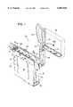
- FIG. 1is an isometric view showing a stowable support apparatus constructed according to a preferred embodiment of the invention and showing a display unit in dashed lines.
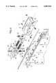
- FIG. 2is a side elevation view of the apparatus shown in FIG. 1 in its stowed position, with a portion of the housing broken away to show details of internal construction.
- FIG. 3is a rear elevation view of the apparatus shown in FIG. 2.
- FIG. 4is a front elevation view of the apparatus shown in FIG. 2.
- FIG. 5is an isometric, partially exploded view of the track, lock mechanism and slide of the apparatus shown in FIG. 1.
- FIG. 6is an enlarged, cross-sectional view of the track and slide shown in FIG. 1, taken along line 6--6 in FIG. 1.
- FIG. 7is a bottom plan view of the slide and lock mechanism shown in FIG. 2.
- FIG. 8is a top plan view of the cam block of the slide shown in FIG. 5.
- FIG. 9is an isometric view of the cam block shown in FIG. 8.
- FIG. 10is an exploded view of the support arm and mounting bracket of the apparatus shown in FIG. 1.
- FIG. 11is a side elevation view of the apparatus shown in FIG. 2, with the slide uncoupled from the lock mechanism and urged away from the lock mechanism to partially remove the display unit from the housing.
- FIG. 12is a side elevation view of the apparatus shown in FIG. 11 in an intermediate position, with the display unit fully removed from the housing and the handle pivoted to a horizontal position.
- FIG. 13is a side elevation view of the apparatus shown in FIG. 12 with the support arm pivoted to a vertical position.
- FIG. 14is a side elevation view of the apparatus shown in FIG. 13 with the display unit rotated to a user-viewable position.
- FIGS. 1-4A stowable support apparatus constructed according to a preferred embodiment of the present invention is shown in FIGS. 1-4 and indicated generally at 10.
- Apparatus 10includes a housing 12 and an elongate track 14.
- a lock mechanism 16is mounted adjacent one end of track 14, and a slide 18 is mounted on track 14 and reciprocally moveable thereon.
- a mounting bracket 20 with a handle 22provides a mounting surface 24 for a display unit 26 (shown in dashed lines in FIGS. 1 and 2) and is pivotally coupled to slide 18 by a support arm 28.
- housing 12includes a pair of generally rectangular side walls 30. End walls 32 extend between side walls 30 to connect and maintain side walls 30 in a spaced-apart relationship to each other, thereby defining a cavity 34 therebetween. Each side wall 30 is a solid surface, which protects display unit 26 when it is stored within housing 12, however it should be understood that side walls 30 may have a frame-like structure as well. As shown, end walls 32 extend between and at least partially along three of the sides of the pair of side walls 30, with the space between one set of corresponding sides being substantially open to define an opening 36 to permit display unit 26 to be inserted into and removed from cavity 34. As shown, housing 12 is shaped to closely conform to the shape of display unit 26.
- Housing 12is configured to be mounted within or adjacent a seat in the passenger compartment of an airplane, bus, etc.
- housing 12is installed adjacent or within the arm rest portion of a seat, with opening 36 extending away from the back-supporting portion of the seat.
- display unit 26When display unit 26 is not being used, it may be stowed within cavity 34, as shown in FIG. 2. In its stowed position, display unit 26 is protected by housing 12 and stored in an out-of-the-way position where it will not inconvenience or obstruct users and other passengers and crew moving about the passenger area, getting into and out of their seats, and performing other activities.
- the displayis slidable out of cavity 34 and selectively adjustable to a desired viewing position, as discussed subsequently.
- Track 14is shown in FIGS. 5 and 6 and extends along the outer surface of one of the housing's end walls 32. As shown, track 14 is recessed inwardly from and extends generally parallel to the top edge of each side wall 30 and extends along the length thereof. Track 14 includes an elongate planar member 38 with a first channel 40 extending along a substantial portion of the length thereof. Member 38 is supported above end wall 32 to give track 14 a generally T-shaped cross-sectional configuration, with second and third channels 42 and 44, respectively, defined in a longitudinally extending and laterally spaced relationship adjacent opposite sides of the base of member 38, as shown in FIG. 6. Preferably, channels 40-44, as well as the other moving parts described herein, are lubricated with a suitable lubricant, such as a teflon grease, to facilitate the smooth movement of slide 18 along track 14.
- a suitable lubricantsuch as a teflon grease
- Lock mechanism 16is mounted adjacent one end of track 14 and is configured to selectively engage slide 18 to retain the slide, as well as support arm 28, in a defined position with respect to track 14.
- Lock mechanism 16is shown in FIGS. 5 and 7 and includes a base 46, which is secured on track 14 and, as shown in FIG. 5, is mounted on the region of track 14 that extends beyond the periphery of housing 12.
- Base 46includes a recess 48 into which a pawl 50 is pivotally mounted and configured to selectively engage slide 18, as discussed below.
- Pawl 50includes an engagement portion 51 and a mount 52, which is secured on base 46 by a locking bearing 54 and a fastener, namely screw 56.
- pawl 50is secured on base 46, but is still pivotal from its mounted position in a plane extending generally parallel to track 14 within a range defined by the walls of recess 48. Furthermore, screw 56 is passed through a spring 58, as shown in FIG. 5, which enables pawl 50 to deflect slightly upward or downward from this horizontal plane and then be returned to this neutral plane. A washer 60 retains spring 58 between the head of screw 56 and pawl 50.
- Lock mechanism 16further includes a bias mechanism, which is generally indicated at 62 in FIG. 5 and which is configured to urge slide 18 away from lock mechanism 16.
- bias mechanism 62includes a pair of springs 64, which are each partially received within a corresponding pair of sockets 66 in base 46 and retained therein by a pair of pins 68.
- Slide 18is shown in FIGS. 5-7. As shown, slide 18 is mounted on track 14 and is reciprocally movable thereon. Slide 18 includes a housing 70, with a pair of flange-like downwardly extending projections 72, that are best seen in FIGS. 6 and 7. Projections 72 engage opposite sides of the track's planar member 38 to secure slide 18 on the track. Each projection 72 further includes a first guide member 74 that extends downwardly from a corresponding one of projections 72 and is configured to be received and travel within the track's second or third channels 42 and 44, respectively.
- channels 42 and 44are open-ended, in that first guide members 74 may be inserted within the channels from one end of track 14, namely the end on which lock mechanism 16 is mounted, but cannot be removed from channels 42 and 44 from the other end of track 14. Therefore, once slide 18 is mounted on track 14 and lock mechanism 16 is subsequently secured on the track, slide 18 cannot be removed from track 14 without disassembling apparatus 10. Slide 18 is constrained from jamming or rocking as it reciprocates along track 14 because it engages track 14 at two spaced-apart regions along the long axis of the track.
- slide 18is of a sufficient length that it simultaneously contacts track 14 from two spaced-apart regions along the long axis of track 14 to provide a smooth, steady motion along the track.
- Slide 18 firerincludes a cam block 76 that is secured to housing 70 by a pair of lateral screws 78 and a larger central screw 80, which are shown in FIG. 5.
- screw 80includes a second guide member 82 that extends downwardly through housing 70 and is received and travels at least partially within first channel 40 to guide and stabilize the movement of slide 18 along track 14.
- cam block 76includes a plurality of interconnected cams or detents 84-90, which are configured to be engaged sequentially by pawl 50 as slide 18 is brought into and removed from engagement with lock mechanism 16.
- cams 84-90form a generally M-shaped configuration, with cams 84 and 90 extending generally parallel to the long axis of track 14, and cams 86 and 88 extending therebetween and generally orthogonal to each other.
- cams 84-90are oriented at differing heights with respect to each other, and as such define walls 92-96 that cooperate with cams 84-90 to create a one-way, sequential path through the cams, as indicated by arrows in FIG. 8.
- Block 76further includes a forward surface 98, which is upwardly and laterally inclined, and as a result orients pawl 50 to be received by cam 84 regardless of the initial angular orientation of pawl 50 with respect to slide 18.
- cam block 76engages and compresses springs 64 of bias mechanism 62. Engagement portion 51 of pawl 50 engages forward surface 98 of block 76, thereby causing pawl 50 to pivot horizontally so that portion 51 is aligned to be received into first cam 84. As slide 18 continues moving toward lock mechanism 16, the pawl's forward portion 51 passes through cam 84 and enters cam 86. Because portion 51 passes over wall 92, it cannot reenter or be removed from block 76 through cam 84. Instead, it is pushed to the portion of cam 86 distal forward surface 98. When slide 18 is released by the user, bias mechanism 62 urges slide 18 away from lock mechanism 16. As this occurs, portion 51 is guided by cam 86 over wall 94 and into cam 88, where it is received into its locked position, shown in dashed lines in FIG. 8. Once secured, slide 18 is maintained in a defined, stowed position with respect to track 14.
- lock mechanism 16To release slide 18 from engagement with lock mechanism 16, slide 18 is once again urged toward lock mechanism 16. Because portion 51 passed over wall 94, it cannot reenter cam 86, and instead is guided along cam 88, over wall 96 and into the portion of cam 90 distal forward surface 98. Once the force being exerted by the user on slide 18 is removed, bias mechanism 62 once again urges slide 18 away from lock mechanism 16, thereby causing portion 51 to be withdrawn from cam block 76 through cam 90. Because lock mechanism 16 is selectively actuated by successive engagements with slide 18, lock mechanism 16 may also be referred to as a push-button mechanism. Furthermore, when apparatus 10 is installed in or adjacent a seat or the arm rest of a seat, handle 22 of mounting block 20 is most commonly the portion of apparatus 10 that a user grips to cause the actuation of lock mechanism 16.
- slide 18is pivotally coupled to a support arm 28, which in turn is pivotally coupled to mounting block 20.
- Support arm 28is shown in FIG. 10 and includes first and second pivot assemblies 100 and 102.
- Each pivot assembly 100 and 102includes first and second knuckles 104 and 106 that house a finger 108 and are joined by a fastener, namely screw 110 and lock washer 112.
- a plurality of spacers 114 and washers 116may be inserted between finger 108 and knuckles 104 and 106.
- Each knuckle 104 and 106includes an elongate stem portion 118 that is inserted into a body member 120 and retained therein by screws 121.
- body member 120is hollow and has a generally rectangular cross-sectional configuration sized to receive and establish communication between stem portions 118 of first knuckles 104 of pivot assemblies 100 and 102.
- each first knuckle 104includes a central passage 122 through which the display unit's power and/or communication cord 166 is threaded and protected from being cut or otherwise damaged.
- Pivot assembly 100is coupled to a slide pivot 124 to enable slide 18 and support arm 28 to pivot with respect to each other.
- Slide pivot 124includes a base 126, which is inserted into the end of slide 18 distal lock mechanism 16, and a pair of teeth 128 and 130 that are respectively coupled between first knuckle 104, finger 108 and second knuckle 106.
- Slide pivot 124further includes an aperture 132 through which a set screw 134 is inserted and used to adjust the parallel of support arm 28.
- Pivot assembly 102is coupled to mounting bracket 20, and specifically to a display pivot 136, to enable support arm 28 and mounting bracket 20 to pivot with respect to each other in the same plane as support arm 28 and slide 18.
- support arm 28 and slide 18preferably enable relative movement of display unit 26 in his plane only.
- the pivot axes of each pivot assembly 100 and 102 and either slide pivot 124 or display pivot 136are parallel and spaced-apart from each other and are orthogonal to the plane.
- Display pivot 136is similar in configuration to slide pivot 124, and it includes a pair of teeth 138 and 140 that are respectively spaced between first knuckle 104, finger 108 and second knuckle 106 of pivot assembly 102.
- display pivot 136includes a spindle 142 distal teeth 138 and 140 that enables rotational movement of display unit 26 about an axis transverse to the pivot axes of pivot assemblies 100 and 102.
- mounting bracket 20further includes a tilt assembly 144 that is retained on spindle 142 by a clamp 145, which is shaped to conform to the configuration of spindle 142 and which is coupled to assembly 144 by a pair of screws 146 and lock washers 148.
- a dowel pin 150is inserted, usually press fit, through a rotational washer 152 and partially into an aperture 154 in display pivot 136 to limit the rotational path of display unit 26 with respect to support arm 28.
- the end of pin 150 that is not inserted into pivot 136is received within an arcuate cavity (not shown) in tilt assembly 144.
- mounting bracket 20 (and display unit 26)are able to rotate approximately 900 in the direction indicated with an arrow in FIG. 10.
- pin 150 and aperture 154could be located in a similar position on the opposite side of tilt assembly 144 to enable rotation in the opposite direction. Because of this selective range of rotation, apparatus 10 can be configured to rotate out of the previously described pivot plane in a specified direction. Therefore, it is possible to design what may be referred to as right-hand units and left-hand units, depending on the direction in which the display unit is able to be rotated out of the pivot plane.
- mounting bracket 20could not include a dowel pin, thereby enabling a full 360° of rotational motion.
- Mounting bracket 20also includes a base 156 that is coupled to the end of tilt assembly 144 distal display pivot 136.
- Base 156provides a mounting surface 24 on which display unit 26 is mounted.
- base 156is pivotally connected to tilt assembly 144 by a screw 158 that is passed through a pair of ears 159 extending on either side of a portion of base 156. This enables base 156 to pivot a limited degree about an axis that is transverse to both the previously discussed pivot axes of support arm 28 as well as the axis of rotation of mounting bracket 20 about spindle 142. This added degree of adjustment further enables apparatus 10 to selectively adjust to the particular preferred viewing angles of any given user.
- a pair of locking brakes 157are mounted on opposing side walls of tilt assembly 144 to control the force a user must exert to cause base 156 to tilt with respect to tilt assembly 144. As shown, a set screw 155 extends through tilt assembly 144 to adjust the portion of one of locking brakes 157, thereby controlling the outward force or friction on coverplate 162.
- Cover plates 160 and 162are secured to base 156 with screws or other suitable fasteners (not shown) to protect display unit 26 when it is mounted on base 156 and prevent its unwanted removal from apparatus 10.
- Base 156 and plate 162engage and support adjacent sides of display unit 26 to provide additional support and stability to the display.
- plate 162includes a handle 22 configured to be gripped by the user to adjust and position apparatus 10.
- handle 22includes a removed region, such as aperture 164 through which at least a portion of a user's hand can be passed so that the user can establish a secure, firm grip on handle 22.
- cord 166is threaded through support arm 28 and mounting bracket 22.
- Cord 166establishes communication between display unit 26 and a power source and/or a source of data, information, etc. via plug 168, which is inserted into display unit 26.
- cord 166is supported by a retaining clip 170 prior to its entry into support arm 28.
- Cord 166is then passed through one of a pair of lateral apertures 172 in slide 18, through first knuckles 104 on pivot assemblies 100 and 102, which define a protective conduit for cord 166 through support arm 28, through central apertures in spindle 142 and tilt assembly 144, and finally through an exit port 174 in base 156 of mounting bracket 20.
- cord 166Threaded through slide 18, support arm 28 and mounting bracket 20, as described above, cord 166 is supported and positioned for connection to display unit 26, while at the same time being maintained free from interference with the operation and adjustment of apparatus 10, and specifically the mutually engaging portions of slide 18 and lock mechanism 16, as well as the pivotal and rotational adjustments of support arm 28 and mounting bracket 20.
- lock mechanism 16is actuated by urging slide 18 toward lock mechanism 16 to actuate the lock mechanism and release pawl 51 from its locked position, which is shown in dashed lines in FIG. 8. Because handle 22 is generally the prominent portion of apparatus 10 that is readily accessible to the user when apparatus 10 is installed, the user should simply urge handle 22 in the direction of lock mechanism 16 to actuate the lock mechanism and release slide 18. If handle 22 is subsequently released by the user, bias mechanism 62 urges slide 18 away from lock mechanism 16 approximately to a position shown in FIG. 11. As shown, display unit 26 is partially removed from housing 12 as slide 18 travels along track 14 away from lock mechanism 16.
- Display unit 26is next drawn fully out of housing 12, preferably by the user grasping handle 22 and pulling the handle along the long axis of track 14 in a direction away from lock mechanism 16. Once slide 18 reaches the end of its slidable path along track 14, slide 18 is prevented from moving further away from lock mechanism 16 and the force exerted by the user causes handle 22 to pivot to a horizontal position, as shown in FIG. 12. In this position, display unit 26 is extended in its furthest position away from the user.
- apparatus 10may include a variety of stops for preventing slide 18 from sliding off of the end of track 14 distal lock mechanism 16.
- One suitable waydiscussed previously, is for second and third channels 42 and 44 to be closed-ended distal lock mechanism 16, thereby stopping the movement of first guides 74, once they contact this closed end region.
- FIG. 13the user draws display unit 26 upwardly and toward the user.
- This motioncauses support arm 28 to pivot at is connection to slide 18 to a generally vertical position, which is shown in FIG. 13.
- display unit 26is at its user-viewable height, but is oriented to face laterally away from the user.
- To adjust display unit 26 to a user-viewable positionit is rotated to the position shown in FIG. 14.
- To return apparatus 10 to its stowed positionthe above-recited process is repeated in reverse order.
- apparatus 10may be installed in other orientations with respect to the user, depending on the space requirements of a particular seating arrangement.
- apparatus 10may be installed within a wall or other structure and oriented so that opening 36 is at right angles to the user.
- display unit 26, and specifically mounting bracket 20 on which the display unit is mountedis rotational out of the pivot plane, it is selectively adjustable within this rotational range to suit the preferred viewing angle of a particular user.
- support arm 28can be pivoted from vertical position to impart this angled orientation to the display unit.
- all positional adjustments to apparatus 10are preferably actuated by the user grasping handle 22.
- Handle 22includes a user-gripable region designed to enable the user to firmly and securely grasp the handle.
- the userwill not damage or get dirt and oil on display unit 26 and will not put stress on the display unit or its connection to mounting bracket 20.
- each of the above-described pivotal and rotational connectionsshould have sufficient frictional or other resistance that they will not freely adjust if the vehicle on which apparatus 10 is installed suddenly changes direction or speed. This eliminates the danger of a sudden start, stop or turn causing apparatus 10 to swing out of control and strike a passenger or impact another object.
- apparatus 10When apparatus 10 is struck by a passenger or another object, it is designed to automatically adjust to a safe, partially stowed position. Specifically, because mounting bracket 20 preferably only enables rotational motion out of the pivot plane of support arm 28 within a range of approximately 90°, if the user is thrown forward into mounting bracket 20 or display unit 26, it will rotate from the user-viewable position shown in FIG. 14 to the position shown in FIG. 13. It the user or other object continues to impact or otherwise put force on apparatus 10, support arm 28 will pivot from its position shown in FIG. 13 to a generally horizontal position shown in FIG. 12. Furthermore, mounting bracket 20 will collapse from its horizontal position shown in FIG. 12 to a generally vertical position, such as is shown in FIG. 11.
Landscapes
- Engineering & Computer Science (AREA)
- Aviation & Aerospace Engineering (AREA)
- Mechanical Engineering (AREA)
- Fittings On The Vehicle Exterior For Carrying Loads, And Devices For Holding Or Mounting Articles (AREA)
- Devices For Indicating Variable Information By Combining Individual Elements (AREA)
Abstract
Description
Claims (21)
Priority Applications (3)
| Application Number | Priority Date | Filing Date | Title |
|---|---|---|---|
| US08/936,027US6007036A (en) | 1997-09-23 | 1997-09-23 | Stowable support apparatus |
| PCT/US1998/019942WO1999015742A1 (en) | 1997-09-23 | 1998-09-23 | Stowable support apparatus |
| AU95055/98AAU9505598A (en) | 1997-09-23 | 1998-09-23 | Stowable support apparatus |
Applications Claiming Priority (1)
| Application Number | Priority Date | Filing Date | Title |
|---|---|---|---|
| US08/936,027US6007036A (en) | 1997-09-23 | 1997-09-23 | Stowable support apparatus |
Publications (1)
| Publication Number | Publication Date |
|---|---|
| US6007036Atrue US6007036A (en) | 1999-12-28 |
Family
ID=25468073
Family Applications (1)
| Application Number | Title | Priority Date | Filing Date |
|---|---|---|---|
| US08/936,027Expired - LifetimeUS6007036A (en) | 1997-09-23 | 1997-09-23 | Stowable support apparatus |
Country Status (3)
| Country | Link |
|---|---|
| US (1) | US6007036A (en) |
| AU (1) | AU9505598A (en) |
| WO (1) | WO1999015742A1 (en) |
Cited By (71)
| Publication number | Priority date | Publication date | Assignee | Title |
|---|---|---|---|---|
| US6179263B1 (en)* | 1997-10-14 | 2001-01-30 | Rosen Products Llc | Stowable support apparatus |
| US6286801B1 (en)* | 1999-07-15 | 2001-09-11 | Gary J. Collins | Apparatus for holding books |
| US20020058807A1 (en)* | 2000-09-29 | 2002-05-16 | Giandomenico Christen M. | Process for preparation of N-1 protected N ring nitrogen containing cyclic polyamines and products thereof |
| US6409242B1 (en)* | 2000-11-14 | 2002-06-25 | Chung L. Chang | Flat thin screen T/V monitor automotive roof mount |
| US20020162930A1 (en)* | 2000-08-22 | 2002-11-07 | Satoru Kimura | Installation device |
| US6629738B2 (en)* | 2000-09-19 | 2003-10-07 | Arturo Salice S.P.A. | Grease-damped drawer-closing apparatus |
| US6634904B2 (en)* | 2001-10-03 | 2003-10-21 | The Boeing Company | Airplane seat computer connection |
| US20040046487A1 (en)* | 2002-09-05 | 2004-03-11 | Olivera Argelio M. | Surgical console |
| US20040056829A1 (en)* | 2002-02-06 | 2004-03-25 | Libby James B. | Automated multi-task window assembly |
| US6719343B2 (en) | 2001-03-22 | 2004-04-13 | Lear Corporation | Vehicle console assembly |
| US6758521B2 (en)* | 2001-09-05 | 2004-07-06 | Honda Giken Kogyo Kabushiki Kaisha | In-vehicle monitor support structure |
| US6789775B2 (en) | 2002-08-28 | 2004-09-14 | News America, Inc. | Flexible connection system for a mounting device |
| US6824213B2 (en)* | 2003-04-28 | 2004-11-30 | Be Aerospace, Inc. | Passenger seat with seat electronics unit and beam therefor |
| US20050002155A1 (en)* | 2003-07-03 | 2005-01-06 | Latino Richard M. | Computer monitor lift and storage mechanism |
| US20050140191A1 (en)* | 2003-12-11 | 2005-06-30 | Thomas Curran | Stowable seat mounted display screen |
| US20050218706A1 (en)* | 2004-03-30 | 2005-10-06 | Stefan Schikora | Vehicle seat, especially an aircraft passenger seat |
| US20050224651A1 (en)* | 2004-03-20 | 2005-10-13 | Gerd Glockler | Apparatus for attachment of a unit to attachment devices in a vehicle |
| US7036879B2 (en) | 2002-08-14 | 2006-05-02 | Johnson Safety, Inc. | Headrest-mounted monitor |
| US7044546B2 (en) | 2002-08-14 | 2006-05-16 | Johnson Safety, Inc. | Headrest-mounted monitor |
| USD521524S1 (en) | 2004-01-08 | 2006-05-23 | Johnson Safety, Inc. | Multi-media player enclosure |
| US7084932B1 (en) | 1999-12-28 | 2006-08-01 | Johnson Controls Technology Company | Video display system for a vehicle |
| US20060169188A1 (en)* | 2003-07-03 | 2006-08-03 | Latino Richard M | Electrically-driven computer monitor lift and storage assembly |
| US7109959B2 (en) | 2002-02-06 | 2006-09-19 | Andersen Corporation | Multi-task window |
| US20060219857A1 (en)* | 2005-03-31 | 2006-10-05 | Satterfield Johnny A | Deployable video arm |
| US20060242671A1 (en)* | 2005-04-20 | 2006-10-26 | Vitito Christopher J | Vehicle entertainment system incorporated within the armrest/console of a vehicle with a swivel monitor mounting structure |
| US20060258441A1 (en)* | 2005-04-20 | 2006-11-16 | Vitito Christopher J | Vehicle entertainment system incorporated within the armrest/console of a vehicle |
| US20060258440A1 (en)* | 2005-04-20 | 2006-11-16 | Vitito Christopher J | Detachable vehicle entertainment system for the armrest/console of a vehicle |
| US20060274495A1 (en)* | 2003-12-17 | 2006-12-07 | Hiroshi Nakamura | Supporting device having cable extending between two housings |
| US7178871B1 (en)* | 1998-10-15 | 2007-02-20 | British Airways Plc | Seating unit |
| US20070215054A1 (en)* | 2006-03-17 | 2007-09-20 | Allied Precision Industries, Inc. | Pet Platform Assembly |
| US20070290536A1 (en)* | 2006-06-20 | 2007-12-20 | Lear Corporation | Pop-up display |
| US20080001866A1 (en)* | 2006-06-28 | 2008-01-03 | Martin Michael M | Control Display Positioning System |
| US20080035030A1 (en)* | 2004-07-01 | 2008-02-14 | Adeptias Limited | Item of Furniture |
| US20080125761A1 (en)* | 2006-09-18 | 2008-05-29 | David Weston | Ophthalmic surgical console system |
| US20090089841A1 (en)* | 2007-10-01 | 2009-04-02 | Lear Corporation | Seat-mounted electronics assembly |
| US20090140615A1 (en)* | 2004-01-23 | 2009-06-04 | Basil Norman Freeman | Apparatus for supporting an audio/video system which includes a thin screen video display unit |
| US20090152418A1 (en)* | 2007-12-12 | 2009-06-18 | Bury Sp Z O.O. | Portable electronic device holder, especially for a dashboard of a car |
| US7591508B2 (en) | 2005-11-02 | 2009-09-22 | Chung Lung Chang | Headrest mounted entertainment system |
| US20090302158A1 (en)* | 2005-12-23 | 2009-12-10 | British Airways Plc | Aircraft Passenger Seat |
| US7636930B2 (en) | 2002-10-28 | 2009-12-22 | Johnson Safety, Inc. | Mobile video system |
| US20100096958A1 (en)* | 2007-03-14 | 2010-04-22 | Tempus Computers Limited | Handle Latch |
| US20100164336A1 (en)* | 2004-12-10 | 2010-07-01 | Starpath Co., Ltd | Receipt type display device |
| US7758117B2 (en) | 2005-11-02 | 2010-07-20 | Chung Lung Chang | Headrest-mounted entertainment systems |
| US7762627B2 (en) | 2005-11-02 | 2010-07-27 | Chung Lung Chang | Headrest-mounted entertainment systems |
| US20100244505A1 (en)* | 2009-03-31 | 2010-09-30 | Gm Global Technology Operations, Inc. | Video Screen Assembly For Vehicle |
| US7812784B2 (en) | 2005-11-02 | 2010-10-12 | Chung Lung Chang | Headrest mounted entertainment system |
| US7997211B2 (en) | 2006-06-12 | 2011-08-16 | Steelcase Inc. | Wall mounted workstation |
| US20110205032A1 (en)* | 2010-02-25 | 2011-08-25 | Toshiba Tec Kabushiki Kaisha | Display device |
| DE102010019849A1 (en)* | 2010-05-07 | 2011-11-10 | Recaro Aircraft Seating Gmbh & Co. Kg | Seat hitch |
| US20110278885A1 (en)* | 2010-05-14 | 2011-11-17 | John Procter | Coupling assembly |
| US8104850B2 (en) | 2007-05-30 | 2012-01-31 | Steelcase Inc. | Furniture storage unit |
| US20130001389A1 (en)* | 2009-03-30 | 2013-01-03 | Weber Aircraft Llc | Deployment apparatuses |
| US8388060B2 (en) | 2007-04-16 | 2013-03-05 | Chung Lung Chang | Headrest-mounted entertainment systems |
| US20130193173A1 (en)* | 2008-08-28 | 2013-08-01 | Anthony P. Bonito | Golf car and mounting system for a display device incorporated therein |
| US20150048230A1 (en)* | 2012-03-22 | 2015-02-19 | Johnny A. Satterfield | Video arm assembly |
| US9010852B1 (en)* | 2011-12-19 | 2015-04-21 | TIMCO Aviation Services | In-arm monitor seat |
| US20150274295A1 (en)* | 2014-04-01 | 2015-10-01 | Zim Flugsitz Gmbh | Holding device for a display and/or operating unit for attaching in an aircraft and display and operating device with a holding device |
| US20160340041A1 (en)* | 2015-05-22 | 2016-11-24 | Dassault Aviation | Retractable support for a screen and interior layout assembly of an aircraft cabin comprising such a support |
| US20160340042A1 (en)* | 2015-05-22 | 2016-11-24 | Dassault Aviation | Retractable support for a screen, and aircraft cabin seat comprising such a support |
| US20170002972A1 (en)* | 2013-07-09 | 2017-01-05 | Zodiac Seats Us Llc | Friction stop device |
| US20170158008A1 (en)* | 2015-03-23 | 2017-06-08 | Terry Nehring | Trailer Weight Distribution Hitch System Storage Device |
| US10144327B2 (en)* | 2017-01-20 | 2018-12-04 | Toyota Motor Engineering & Manufacturing North America, Inc. | Vehicle seat with a reconfigurable side armrest |
| US10322805B2 (en) | 2013-01-07 | 2019-06-18 | Safran Seats Usa Llc | Video arm deployment method |
| US10442537B2 (en)* | 2017-07-20 | 2019-10-15 | Johnny A. Satterfield | Deployable table assembly |
| US20190323649A1 (en)* | 2016-11-10 | 2019-10-24 | Safran Seats Usa Llc | Concentric video arm pivot mechanism |
| US20200405569A1 (en)* | 2019-06-28 | 2020-12-31 | Fuji Medical Instruments Mfg. Co., Ltd. | Chair-Type Massage Machine |
| US11904812B2 (en) | 2019-12-12 | 2024-02-20 | Reinhold Industries, Inc. | Passenger vehicle personal electronic device holders |
| US20240075854A1 (en)* | 2022-09-01 | 2024-03-07 | Deonne Williams | Child Carseat Mountable Electronic Device Mounting Device |
| IT202200022686A1 (en)* | 2022-11-04 | 2024-05-04 | Ferrari Spa | CONTENT DISPLAY DEVICE FOR ROAD VEHICLE AND RELATED ROAD VEHICLE |
| IT202200022650A1 (en)* | 2022-11-04 | 2024-05-04 | Ferrari Spa | CONTENT DISPLAY DEVICE FOR ROAD VEHICLE AND RELATED ROAD VEHICLE |
| IT202200022668A1 (en)* | 2022-11-04 | 2024-05-04 | Ferrari Spa | CONTENT DISPLAY DEVICE FOR ROAD VEHICLE AND RELATED ROAD VEHICLE |
Families Citing this family (3)
| Publication number | Priority date | Publication date | Assignee | Title |
|---|---|---|---|---|
| KR101966614B1 (en)* | 2012-10-05 | 2019-04-08 | 현대모비스 주식회사 | Mounting apparatus for monitor in vehicle |
| US9718551B2 (en)* | 2015-07-16 | 2017-08-01 | Goodrich Corporation | Frontal entry phone cord funnel |
| KR102299333B1 (en)* | 2017-01-04 | 2021-09-09 | 현대자동차주식회사 | Mobility container apparatus of vehicle |
Citations (23)
| Publication number | Priority date | Publication date | Assignee | Title |
|---|---|---|---|---|
| US2514655A (en)* | 1946-02-12 | 1950-07-11 | Frank J Luketa | Reclining chair |
| US4455008A (en)* | 1980-12-22 | 1984-06-19 | Mackew James | Modular support system |
| US4573854A (en)* | 1983-12-23 | 1986-03-04 | Mcfarland Robert E | Apparatus for loading a wheelchair or similar object |
| US4620808A (en)* | 1984-04-09 | 1986-11-04 | Protype Corporation | Display typewriter |
| US4708312A (en)* | 1985-10-23 | 1987-11-24 | Ncr Corporation | Extensible height-adjustable swivel arm for supporting a display or the like |
| US4735467A (en)* | 1986-05-23 | 1988-04-05 | Westinghouse Electric Corp. | Stow away flat screen mechanism |
| US4836486A (en)* | 1987-04-16 | 1989-06-06 | Anthro Corporation | Adjustable support |
| EP0368609A2 (en)* | 1988-11-08 | 1990-05-16 | Sony Corporation | Apparatus for attaching a display monitor to a seat |
| US4982996A (en)* | 1989-02-17 | 1991-01-08 | Fiat Auto S.P.A. | Automotive seating system featuring a television set |
| US5076524A (en)* | 1990-12-27 | 1991-12-31 | Sony Trans Com, Inc. | TV/LCD pop-up stowage retraction means |
| US5177616A (en)* | 1991-12-02 | 1993-01-05 | Matsushita Avionics Systems | Stowable video display assembly |
| US5179447A (en)* | 1991-04-16 | 1993-01-12 | Hughes-Avicom International, Inc. | Personal video player and monitor assembly for airline passenger seat console |
| US5195709A (en)* | 1989-03-10 | 1993-03-23 | Koito Industries, Ltd. | Television receiver supporting structure of arm rest |
| US5271590A (en)* | 1992-01-31 | 1993-12-21 | Rosen John B | Articulable projecting plug |
| US5311302A (en)* | 1992-07-02 | 1994-05-10 | Hughes Aircraft Company | Entertainment and data management system for passenger vehicle including individual seat interactive video terminals |
| US5360150A (en)* | 1992-05-04 | 1994-11-01 | Praz Jean Luc | Roof rack for vehicles |
| US5374104A (en)* | 1992-05-21 | 1994-12-20 | Weber Aircraft, Inc. | Armrest with video deployment system |
| US5379978A (en)* | 1994-02-04 | 1995-01-10 | Manchester Plastics | Vehicular convertible cupholder |
| USD363927S (en) | 1993-12-20 | 1995-11-07 | Rosen John B | Support mount for flat screen televisions |
| USD367477S (en) | 1994-09-30 | 1996-02-27 | Rosen John B | Monitor support |
| US5547248A (en)* | 1993-05-26 | 1996-08-20 | Societe Industrielle Et Commerciale De Materiel Aeronautique | Passenger seat for a public transport vehicle, the seat including a video display which can be retracted into an armrest |
| US5611513A (en)* | 1992-01-31 | 1997-03-18 | Rosen; John B. | Articulable projecting plug |
| US5692718A (en)* | 1995-03-04 | 1997-12-02 | Fischerwerke, Arthur Fischer Gmbh & Co. | Holding device for drink container |
- 1997
- 1997-09-23USUS08/936,027patent/US6007036A/ennot_activeExpired - Lifetime
- 1998
- 1998-09-23WOPCT/US1998/019942patent/WO1999015742A1/enactiveApplication Filing
- 1998-09-23AUAU95055/98Apatent/AU9505598A/ennot_activeAbandoned
Patent Citations (23)
| Publication number | Priority date | Publication date | Assignee | Title |
|---|---|---|---|---|
| US2514655A (en)* | 1946-02-12 | 1950-07-11 | Frank J Luketa | Reclining chair |
| US4455008A (en)* | 1980-12-22 | 1984-06-19 | Mackew James | Modular support system |
| US4573854A (en)* | 1983-12-23 | 1986-03-04 | Mcfarland Robert E | Apparatus for loading a wheelchair or similar object |
| US4620808A (en)* | 1984-04-09 | 1986-11-04 | Protype Corporation | Display typewriter |
| US4708312A (en)* | 1985-10-23 | 1987-11-24 | Ncr Corporation | Extensible height-adjustable swivel arm for supporting a display or the like |
| US4735467A (en)* | 1986-05-23 | 1988-04-05 | Westinghouse Electric Corp. | Stow away flat screen mechanism |
| US4836486A (en)* | 1987-04-16 | 1989-06-06 | Anthro Corporation | Adjustable support |
| EP0368609A2 (en)* | 1988-11-08 | 1990-05-16 | Sony Corporation | Apparatus for attaching a display monitor to a seat |
| US4982996A (en)* | 1989-02-17 | 1991-01-08 | Fiat Auto S.P.A. | Automotive seating system featuring a television set |
| US5195709A (en)* | 1989-03-10 | 1993-03-23 | Koito Industries, Ltd. | Television receiver supporting structure of arm rest |
| US5076524A (en)* | 1990-12-27 | 1991-12-31 | Sony Trans Com, Inc. | TV/LCD pop-up stowage retraction means |
| US5179447A (en)* | 1991-04-16 | 1993-01-12 | Hughes-Avicom International, Inc. | Personal video player and monitor assembly for airline passenger seat console |
| US5177616A (en)* | 1991-12-02 | 1993-01-05 | Matsushita Avionics Systems | Stowable video display assembly |
| US5271590A (en)* | 1992-01-31 | 1993-12-21 | Rosen John B | Articulable projecting plug |
| US5611513A (en)* | 1992-01-31 | 1997-03-18 | Rosen; John B. | Articulable projecting plug |
| US5360150A (en)* | 1992-05-04 | 1994-11-01 | Praz Jean Luc | Roof rack for vehicles |
| US5374104A (en)* | 1992-05-21 | 1994-12-20 | Weber Aircraft, Inc. | Armrest with video deployment system |
| US5311302A (en)* | 1992-07-02 | 1994-05-10 | Hughes Aircraft Company | Entertainment and data management system for passenger vehicle including individual seat interactive video terminals |
| US5547248A (en)* | 1993-05-26 | 1996-08-20 | Societe Industrielle Et Commerciale De Materiel Aeronautique | Passenger seat for a public transport vehicle, the seat including a video display which can be retracted into an armrest |
| USD363927S (en) | 1993-12-20 | 1995-11-07 | Rosen John B | Support mount for flat screen televisions |
| US5379978A (en)* | 1994-02-04 | 1995-01-10 | Manchester Plastics | Vehicular convertible cupholder |
| USD367477S (en) | 1994-09-30 | 1996-02-27 | Rosen John B | Monitor support |
| US5692718A (en)* | 1995-03-04 | 1997-12-02 | Fischerwerke, Arthur Fischer Gmbh & Co. | Holding device for drink container |
Cited By (124)
| Publication number | Priority date | Publication date | Assignee | Title |
|---|---|---|---|---|
| US6179263B1 (en)* | 1997-10-14 | 2001-01-30 | Rosen Products Llc | Stowable support apparatus |
| US7178871B1 (en)* | 1998-10-15 | 2007-02-20 | British Airways Plc | Seating unit |
| US6286801B1 (en)* | 1999-07-15 | 2001-09-11 | Gary J. Collins | Apparatus for holding books |
| US7084932B1 (en) | 1999-12-28 | 2006-08-01 | Johnson Controls Technology Company | Video display system for a vehicle |
| EP1241093A4 (en)* | 2000-08-22 | 2003-05-21 | Matsushita Electric Industrial Co Ltd | SERVICE DEVICE |
| US6811129B2 (en) | 2000-08-22 | 2004-11-02 | Matsushita Electric Industrial Co., Ltd. | Fixture device |
| EP1495962A3 (en)* | 2000-08-22 | 2005-06-29 | Matsushita Electric Industrial Co., Ltd. | Fixture device |
| US20050061938A1 (en)* | 2000-08-22 | 2005-03-24 | Matsushita Electric Industrial Co., Ltd. | Apparatus fixture device and an installation method for fixing an apparatus |
| US20020162930A1 (en)* | 2000-08-22 | 2002-11-07 | Satoru Kimura | Installation device |
| US7191991B2 (en) | 2000-08-22 | 2007-03-20 | Matsushita Electric Industrial Co., Ltd. | Apparatus fixture device and an installation method for fixing an apparatus |
| US20050056755A1 (en)* | 2000-08-22 | 2005-03-17 | Matsushita Electric Industrial Co., Ltd. | Latch device |
| US20070152123A1 (en)* | 2000-08-22 | 2007-07-05 | Matsushita Electric Industrial Co., Ltd. | Installation method for fixing an apparatus |
| US7206181B2 (en) | 2000-08-22 | 2007-04-17 | Matsushita Electric Industrial Co., Ltd. | Latch device |
| US6846053B2 (en)* | 2000-09-19 | 2005-01-25 | Arturo Salice S.P.A. | Grease-dampened drawer closing apparatus |
| US6629738B2 (en)* | 2000-09-19 | 2003-10-07 | Arturo Salice S.P.A. | Grease-damped drawer-closing apparatus |
| US20020058807A1 (en)* | 2000-09-29 | 2002-05-16 | Giandomenico Christen M. | Process for preparation of N-1 protected N ring nitrogen containing cyclic polyamines and products thereof |
| US7379125B2 (en) | 2000-11-14 | 2008-05-27 | Chang Chung L | Flat thin screen TV/monitor automotive roof mount |
| US7894003B2 (en) | 2000-11-14 | 2011-02-22 | Chang Chung L | Flat thin screen TV/monitor automotive roof mount |
| US6409242B1 (en)* | 2000-11-14 | 2002-06-25 | Chung L. Chang | Flat thin screen T/V monitor automotive roof mount |
| US6719343B2 (en) | 2001-03-22 | 2004-04-13 | Lear Corporation | Vehicle console assembly |
| US6758521B2 (en)* | 2001-09-05 | 2004-07-06 | Honda Giken Kogyo Kabushiki Kaisha | In-vehicle monitor support structure |
| US6634904B2 (en)* | 2001-10-03 | 2003-10-21 | The Boeing Company | Airplane seat computer connection |
| US20040056829A1 (en)* | 2002-02-06 | 2004-03-25 | Libby James B. | Automated multi-task window assembly |
| US7109959B2 (en) | 2002-02-06 | 2006-09-19 | Andersen Corporation | Multi-task window |
| US7180489B2 (en) | 2002-02-06 | 2007-02-20 | Andersen Corporation | Automated multi-task window assembly |
| US7044546B2 (en) | 2002-08-14 | 2006-05-16 | Johnson Safety, Inc. | Headrest-mounted monitor |
| US7448679B2 (en) | 2002-08-14 | 2008-11-11 | Chang Chung L | Headrest-mounted monitor |
| US10421411B2 (en) | 2002-08-14 | 2019-09-24 | Voxx International Corporation | Headrest-mounted monitor |
| US7267402B2 (en) | 2002-08-14 | 2007-09-11 | Johnson Safety, Inc. | Headrest-mounted monitor |
| US8585140B2 (en) | 2002-08-14 | 2013-11-19 | Chung L. Chang | Headrest-mounted monitor |
| US9340133B2 (en) | 2002-08-14 | 2016-05-17 | Johnson Safety, Inc. | Headrest-mounted monitor |
| US7036879B2 (en) | 2002-08-14 | 2006-05-02 | Johnson Safety, Inc. | Headrest-mounted monitor |
| US20050023430A1 (en)* | 2002-08-28 | 2005-02-03 | George Kringel | Flexible connection system for a mounting device |
| US6789775B2 (en) | 2002-08-28 | 2004-09-14 | News America, Inc. | Flexible connection system for a mounting device |
| US7044568B2 (en)* | 2002-09-05 | 2006-05-16 | Alcon, Inc. | Surgical console |
| US20040046487A1 (en)* | 2002-09-05 | 2004-03-11 | Olivera Argelio M. | Surgical console |
| US8893193B2 (en) | 2002-10-28 | 2014-11-18 | Johnson Safety, Inc. | Mobile video system |
| US8429694B2 (en) | 2002-10-28 | 2013-04-23 | Chung L Chang | Mobile video system |
| US7636930B2 (en) | 2002-10-28 | 2009-12-22 | Johnson Safety, Inc. | Mobile video system |
| US6824213B2 (en)* | 2003-04-28 | 2004-11-30 | Be Aerospace, Inc. | Passenger seat with seat electronics unit and beam therefor |
| US20050002155A1 (en)* | 2003-07-03 | 2005-01-06 | Latino Richard M. | Computer monitor lift and storage mechanism |
| US7207278B2 (en)* | 2003-07-03 | 2007-04-24 | Wright Line, Llc | Electrically-driven computer monitor lift and storage assembly |
| US20060169188A1 (en)* | 2003-07-03 | 2006-08-03 | Latino Richard M | Electrically-driven computer monitor lift and storage assembly |
| US7063024B2 (en)* | 2003-07-03 | 2006-06-20 | Wright Line, Llc | Computer monitor lift and storage mechanism |
| US7040699B2 (en)* | 2003-12-11 | 2006-05-09 | Daimlerchrysler Corporation | Stowable seat mounted display screen |
| US20050140191A1 (en)* | 2003-12-11 | 2005-06-30 | Thomas Curran | Stowable seat mounted display screen |
| US20060274495A1 (en)* | 2003-12-17 | 2006-12-07 | Hiroshi Nakamura | Supporting device having cable extending between two housings |
| USD521524S1 (en) | 2004-01-08 | 2006-05-23 | Johnson Safety, Inc. | Multi-media player enclosure |
| US20090140615A1 (en)* | 2004-01-23 | 2009-06-04 | Basil Norman Freeman | Apparatus for supporting an audio/video system which includes a thin screen video display unit |
| US7618009B2 (en)* | 2004-03-20 | 2009-11-17 | Intergraph Technologies Company | Apparatus for attachment of a unit to attachment devices in a vehicle |
| US20050224651A1 (en)* | 2004-03-20 | 2005-10-13 | Gerd Glockler | Apparatus for attachment of a unit to attachment devices in a vehicle |
| US20050218706A1 (en)* | 2004-03-30 | 2005-10-06 | Stefan Schikora | Vehicle seat, especially an aircraft passenger seat |
| US7419211B2 (en)* | 2004-03-30 | 2008-09-02 | Recaro Aircraft Seating Gmbh & Co. Kg | Vehicle seat, especially an aircraft passenger seat |
| US20080035030A1 (en)* | 2004-07-01 | 2008-02-14 | Adeptias Limited | Item of Furniture |
| US7748328B2 (en)* | 2004-07-01 | 2010-07-06 | Floreat Fortuna, LLC | Item of furniture |
| US20100164336A1 (en)* | 2004-12-10 | 2010-07-01 | Starpath Co., Ltd | Receipt type display device |
| US20060219857A1 (en)* | 2005-03-31 | 2006-10-05 | Satterfield Johnny A | Deployable video arm |
| EP1863373A4 (en)* | 2005-03-31 | 2011-11-09 | Johnny A Satterfield | DEPLOYABLE VIDEO ARM |
| US7261266B2 (en)* | 2005-03-31 | 2007-08-28 | Satterfield Johnny A | Deployable video arm |
| US20060258441A1 (en)* | 2005-04-20 | 2006-11-16 | Vitito Christopher J | Vehicle entertainment system incorporated within the armrest/console of a vehicle |
| US7604291B2 (en) | 2005-04-20 | 2009-10-20 | Vitito Christopher J | Vehicle entertainment system incorporated within the armrest/console of a vehicle with a swivel monitor mounting structure |
| US20060242671A1 (en)* | 2005-04-20 | 2006-10-26 | Vitito Christopher J | Vehicle entertainment system incorporated within the armrest/console of a vehicle with a swivel monitor mounting structure |
| US8070224B2 (en) | 2005-04-20 | 2011-12-06 | Audiovox Corporation | Vehicle entertainment system incorporated within the armrest/console of a vehicle |
| US7857382B2 (en) | 2005-04-20 | 2010-12-28 | Audiovox Corporation | Detachable vehicle entertainment system for the armrest/console of a vehicle |
| US20060258440A1 (en)* | 2005-04-20 | 2006-11-16 | Vitito Christopher J | Detachable vehicle entertainment system for the armrest/console of a vehicle |
| US8449031B2 (en) | 2005-11-02 | 2013-05-28 | Chung Lung Chang | Headrest-mounted entertainment systems |
| US7591508B2 (en) | 2005-11-02 | 2009-09-22 | Chung Lung Chang | Headrest mounted entertainment system |
| US9004588B2 (en) | 2005-11-02 | 2015-04-14 | Johnson Safety, Inc | Headrest-mounted entertainment systems |
| US7758117B2 (en) | 2005-11-02 | 2010-07-20 | Chung Lung Chang | Headrest-mounted entertainment systems |
| US7762627B2 (en) | 2005-11-02 | 2010-07-27 | Chung Lung Chang | Headrest-mounted entertainment systems |
| US7812784B2 (en) | 2005-11-02 | 2010-10-12 | Chung Lung Chang | Headrest mounted entertainment system |
| US20090302158A1 (en)* | 2005-12-23 | 2009-12-10 | British Airways Plc | Aircraft Passenger Seat |
| US8616643B2 (en) | 2005-12-23 | 2013-12-31 | British Airways Plc | Aircraft passenger seat |
| US20070215054A1 (en)* | 2006-03-17 | 2007-09-20 | Allied Precision Industries, Inc. | Pet Platform Assembly |
| US7669556B2 (en)* | 2006-03-17 | 2010-03-02 | Allied Precision Industries, Inc. | Pet platform assembly |
| US7997211B2 (en) | 2006-06-12 | 2011-08-16 | Steelcase Inc. | Wall mounted workstation |
| US7510241B2 (en)* | 2006-06-20 | 2009-03-31 | Lear Corporation | Pop-up display |
| US20070290536A1 (en)* | 2006-06-20 | 2007-12-20 | Lear Corporation | Pop-up display |
| US20080001866A1 (en)* | 2006-06-28 | 2008-01-03 | Martin Michael M | Control Display Positioning System |
| US8310468B2 (en) | 2006-06-28 | 2012-11-13 | Novartis Ag | Control display positioning system |
| US8262553B2 (en) | 2006-09-18 | 2012-09-11 | Novartis Ag | Ophthalmic surgical console system |
| US20080125761A1 (en)* | 2006-09-18 | 2008-05-29 | David Weston | Ophthalmic surgical console system |
| US20100096958A1 (en)* | 2007-03-14 | 2010-04-22 | Tempus Computers Limited | Handle Latch |
| US8388060B2 (en) | 2007-04-16 | 2013-03-05 | Chung Lung Chang | Headrest-mounted entertainment systems |
| US8104850B2 (en) | 2007-05-30 | 2012-01-31 | Steelcase Inc. | Furniture storage unit |
| US20090089841A1 (en)* | 2007-10-01 | 2009-04-02 | Lear Corporation | Seat-mounted electronics assembly |
| US20090152418A1 (en)* | 2007-12-12 | 2009-06-18 | Bury Sp Z O.O. | Portable electronic device holder, especially for a dashboard of a car |
| US20130193173A1 (en)* | 2008-08-28 | 2013-08-01 | Anthony P. Bonito | Golf car and mounting system for a display device incorporated therein |
| US8944395B2 (en)* | 2008-08-28 | 2015-02-03 | Apple Electric Car, Inc. | Golf car and mounting system for a display device incorporated therein |
| US8523130B2 (en)* | 2009-03-30 | 2013-09-03 | Zodiac Seats Us Llc | Deployment apparatuses |
| US20130001389A1 (en)* | 2009-03-30 | 2013-01-03 | Weber Aircraft Llc | Deployment apparatuses |
| US20100244505A1 (en)* | 2009-03-31 | 2010-09-30 | Gm Global Technology Operations, Inc. | Video Screen Assembly For Vehicle |
| US9152175B2 (en)* | 2010-02-25 | 2015-10-06 | Toshiba Tec Kabushiki Kaisha | Display device |
| US20110205032A1 (en)* | 2010-02-25 | 2011-08-25 | Toshiba Tec Kabushiki Kaisha | Display device |
| DE102010019849A1 (en)* | 2010-05-07 | 2011-11-10 | Recaro Aircraft Seating Gmbh & Co. Kg | Seat hitch |
| US9045096B2 (en)* | 2010-05-14 | 2015-06-02 | Zodiac Seats Us Llc | Coupling assembly |
| US20110278885A1 (en)* | 2010-05-14 | 2011-11-17 | John Procter | Coupling assembly |
| US9758248B2 (en) | 2010-05-14 | 2017-09-12 | Zodiac Seats Us Llc | Coupling assembly |
| US9010852B1 (en)* | 2011-12-19 | 2015-04-21 | TIMCO Aviation Services | In-arm monitor seat |
| US9732901B2 (en)* | 2012-03-22 | 2017-08-15 | Johnny A. Satterfield | Video arm assembly |
| US20150048230A1 (en)* | 2012-03-22 | 2015-02-19 | Johnny A. Satterfield | Video arm assembly |
| US10322805B2 (en) | 2013-01-07 | 2019-06-18 | Safran Seats Usa Llc | Video arm deployment method |
| US20170002972A1 (en)* | 2013-07-09 | 2017-01-05 | Zodiac Seats Us Llc | Friction stop device |
| US9989191B2 (en)* | 2013-07-09 | 2018-06-05 | Zodiac Seats Us Llc | Friction stop device |
| US20150274295A1 (en)* | 2014-04-01 | 2015-10-01 | Zim Flugsitz Gmbh | Holding device for a display and/or operating unit for attaching in an aircraft and display and operating device with a holding device |
| US9617001B2 (en)* | 2014-04-01 | 2017-04-11 | Zim Flugsitz Gmbh | Holding device for a display and/or operating unit for attaching in an aircraft and display and operating device with a holding device |
| US20170158008A1 (en)* | 2015-03-23 | 2017-06-08 | Terry Nehring | Trailer Weight Distribution Hitch System Storage Device |
| US10005332B2 (en)* | 2015-03-23 | 2018-06-26 | Terry Nehring | Trailer weight distribution hitch system storage device |
| US20160340042A1 (en)* | 2015-05-22 | 2016-11-24 | Dassault Aviation | Retractable support for a screen, and aircraft cabin seat comprising such a support |
| US10343778B2 (en)* | 2015-05-22 | 2019-07-09 | Dassault Aviation | Retractable support for a screen and interior layout assembly of an aircraft cabin comprising such a support |
| US20160340041A1 (en)* | 2015-05-22 | 2016-11-24 | Dassault Aviation | Retractable support for a screen and interior layout assembly of an aircraft cabin comprising such a support |
| US10513336B2 (en)* | 2015-05-22 | 2019-12-24 | Dassault Aviation | Retractable support for a screen, and aircraft cabin seat comprising such a support |
| US11629812B2 (en)* | 2016-11-10 | 2023-04-18 | Safran Seats Usa Llc | Concentric video arm pivot mechanism |
| US20190323649A1 (en)* | 2016-11-10 | 2019-10-24 | Safran Seats Usa Llc | Concentric video arm pivot mechanism |
| US10144327B2 (en)* | 2017-01-20 | 2018-12-04 | Toyota Motor Engineering & Manufacturing North America, Inc. | Vehicle seat with a reconfigurable side armrest |
| US10442537B2 (en)* | 2017-07-20 | 2019-10-15 | Johnny A. Satterfield | Deployable table assembly |
| US20200405569A1 (en)* | 2019-06-28 | 2020-12-31 | Fuji Medical Instruments Mfg. Co., Ltd. | Chair-Type Massage Machine |
| US11583467B2 (en)* | 2019-06-28 | 2023-02-21 | Fuji Medical Instruments Mfg. Co., Ltd. | Chair-type massage machine |
| US11904812B2 (en) | 2019-12-12 | 2024-02-20 | Reinhold Industries, Inc. | Passenger vehicle personal electronic device holders |
| US20240075854A1 (en)* | 2022-09-01 | 2024-03-07 | Deonne Williams | Child Carseat Mountable Electronic Device Mounting Device |
| IT202200022686A1 (en)* | 2022-11-04 | 2024-05-04 | Ferrari Spa | CONTENT DISPLAY DEVICE FOR ROAD VEHICLE AND RELATED ROAD VEHICLE |
| IT202200022650A1 (en)* | 2022-11-04 | 2024-05-04 | Ferrari Spa | CONTENT DISPLAY DEVICE FOR ROAD VEHICLE AND RELATED ROAD VEHICLE |
| IT202200022668A1 (en)* | 2022-11-04 | 2024-05-04 | Ferrari Spa | CONTENT DISPLAY DEVICE FOR ROAD VEHICLE AND RELATED ROAD VEHICLE |
| EP4364995A1 (en) | 2022-11-04 | 2024-05-08 | FERRARI S.p.A. | Content display device for road vehicle and relative road vehicle |
Also Published As
| Publication number | Publication date |
|---|---|
| AU9505598A (en) | 1999-04-12 |
| WO1999015742A1 (en) | 1999-04-01 |
Similar Documents
| Publication | Publication Date | Title |
|---|---|---|
| US6007036A (en) | Stowable support apparatus | |
| US5667179A (en) | Ratcheting articulable monitor support and presentation device | |
| US5709360A (en) | Ratcheting articulable monitor support and presentation device | |
| US5177616A (en) | Stowable video display assembly | |
| US6179263B1 (en) | Stowable support apparatus | |
| US5850997A (en) | Articulable projecting plug | |
| US7506843B2 (en) | Computer monitor support device for a vehicle | |
| US8167348B2 (en) | Cable activated latch pawl for floor console armrest | |
| US4852940A (en) | Stowable table system | |
| US5271590A (en) | Articulable projecting plug | |
| CA2399894C (en) | In-vehicle monitor support structure | |
| US5620228A (en) | Drawer device | |
| US5374104A (en) | Armrest with video deployment system | |
| US6698983B1 (en) | Vertically pivoting wheelchair restraint | |
| US20020175254A1 (en) | Adjustable monitor bracket | |
| JP2000025495A (en) | Seat track with rotary lock device | |
| CN106427680B (en) | It is a kind of to enter holding and fixed point return mechanism for the easy of easy entered function seat | |
| US11524785B2 (en) | Tray table pillow for aircraft passenger seat | |
| US5873633A (en) | Retardation lock member for motor vehicle seat component | |
| US20220009391A1 (en) | Armrest Arrangement, Vehicle Seat, and Vehicle | |
| WO2004039625A1 (en) | Central console comprising a display device | |
| JP2003180482A (en) | Armrest | |
| EP3981644B1 (en) | A table unit for a motor-vehicle seat; motor-vehicle seat provided with this unit and motor-vehicle including this seat | |
| JP3054414B1 (en) | Hanging hook device | |
| JPH1042999A (en) | Armrest structure for chair |
Legal Events
| Date | Code | Title | Description |
|---|---|---|---|
| AS | Assignment | Owner name:ADVANCED MULTIMEDIA PRODUCTS CORPORATION DBA ROSEN Free format text:ASSIGNMENT OF ASSIGNORS INTEREST;ASSIGNOR:ROSEN, JOHN B.;REEL/FRAME:009036/0069 Effective date:19980217 | |
| AS | Assignment | Owner name:ROSEN PRODUCTS LLC, OREGON Free format text:MERGER;ASSIGNOR:ADVANCED MULTIMEDIA PRODUCTS CORPORATION, DBA ROSEN PRODUCT DEVELOPMENT, INC.;REEL/FRAME:009949/0362 Effective date:19990331 | |
| STCF | Information on status: patent grant | Free format text:PATENTED CASE | |
| CC | Certificate of correction | ||
| FEPP | Fee payment procedure | Free format text:PAT HOLDER NO LONGER CLAIMS SMALL ENTITY STATUS, ENTITY STATUS SET TO UNDISCOUNTED (ORIGINAL EVENT CODE: STOL); ENTITY STATUS OF PATENT OWNER: LARGE ENTITY Free format text:PAYOR NUMBER ASSIGNED (ORIGINAL EVENT CODE: ASPN); ENTITY STATUS OF PATENT OWNER: LARGE ENTITY | |
| AS | Assignment | Owner name:ROCKWELL COLLINS, INC., IOWA Free format text:ASSIGNMENT OF ASSIGNORS INTEREST;ASSIGNOR:ROSEN PRODUCTS LLC;REEL/FRAME:013438/0893 Effective date:20021219 | |
| FPAY | Fee payment | Year of fee payment:4 | |
| FPAY | Fee payment | Year of fee payment:8 | |
| FPAY | Fee payment | Year of fee payment:12 |