US6006071A - RF communications system operable in the presence of a repetitive interference source and related methods - Google Patents
RF communications system operable in the presence of a repetitive interference source and related methodsDownload PDFInfo
- Publication number
- US6006071A US6006071AUS09/006,071US607198AUS6006071AUS 6006071 AUS6006071 AUS 6006071AUS 607198 AUS607198 AUS 607198AUS 6006071 AUS6006071 AUS 6006071A
- Authority
- US
- United States
- Prior art keywords
- repetitive
- power line
- communication system
- interference source
- data packet
- Prior art date
- Legal status (The legal status is an assumption and is not a legal conclusion. Google has not performed a legal analysis and makes no representation as to the accuracy of the status listed.)
- Expired - Lifetime
Links
Images


Classifications
- H—ELECTRICITY
- H04—ELECTRIC COMMUNICATION TECHNIQUE
- H04B—TRANSMISSION
- H04B15/00—Suppression or limitation of noise or interference
Definitions
- the present inventionrelates to the field of communications, and, more particularly, to a radio frequency (RF) communication system to overcome certain types of repetitive interfering sources.
- RFradio frequency
- Radio frequency communications systemscommonly operate in the presence of interfering sources. Unfortunately, interference may degrade or totally impede communications.
- One particularly troublesome interference sourceis a microwave oven.
- the microwave ovenemits interference in a pulsating manner with a repetition rate equal to that of the power line, and at a 50% duty cycle.
- the nominal repetition periodis 1/60 of a second or once every 16.7 msec.
- Microwave ovenstypically do not include any filtering of the half-wave rectified operating voltage applied to the microwave magnetron.
- the microwave ovenemits a noisy, unstable radio frequency pulse that is controlled by the half-wave rectification of the primary power line frequency.
- the resulting radio frequency interferenceis at a nominal frequency of 2.45 GHz, and presents a difficulty with communications systems sharing this band. This frequency range has also been allocated for certain communications systems, such as wireless local area networks (WLANs).
- WLANswireless local area networks
- a WLANis a flexible data communication system that may be an extension to, or an alternative for, a wired LAN within a building or campus.
- a WLANuses radio technology to transmit and receive data over the air, thereby reducing or minimizing the need for wired connections. Accordingly, a WLAN combines data connectivity with user mobility, and, through simplified configurations, also permits a movable LAN.
- a cordless telephone, home automation communication systems, or a wireless audio speaker systemmay be affected by microwave oven generated interference.
- the interference problem presented by a microwave ovenis addressed, for example, in U.S. Pat. No. 5,574,979 to West and entitled "Periodic Interference Avoidance in a Wireless Radio frequency Communication System".
- the patentdiscloses a hierarchical communication scheme including wireless roaming computing and data collection devices. The system monitors the received signal strength and error rates to determine if the interference is periodic in nature so that the system can predict the future interference and transmit only during off periods of the interference.
- the adjusting protocolcan determine when it is most efficient to stop the communication, and can continue the rest of the communication time interval structure after the interference abates.
- the system for monitoring received signal strength and error ratesis relatively complicated and synchronization may be difficult.
- both a forward and return channelare needed, thereby complicating the system for certain applications.
- U.S. Pat. No. 5,428,669 to McCarthydiscloses a cordless telephone set including a base and a handset. One of the units select alternate frequencies in response to a series of unacknowledged communications, until it receives an acknowledgment on a particular channel. If no acknowledgment is received the system reverts back to the originally selected RF channel.
- a microwave ovenpresents a source of electrical interference that is not readily filtered, and which is capable of causing disruption of communications in a frequency band of the interference.
- Prior attempts to address the periodic interference caused by a microwave ovenhave required relatively complicated circuitry, have required two-way communication, and may not have been robust in the presence of the high interfering signals.
- an RF communication systemfor operating in the presence of a repetitive RF interference source powered from an Alternating Current (AC) power line, and which uses redundant transmission synchronized to the power line to ensure accurate reception by at least one second receiver device.
- ACAlternating Current
- the repetitive RF interference sourcehas repetitive ON and OFF periods based upon the AC power line
- the RF communication systemcomprises a first device powered from an AC power line which also powers the repetitive RF interference source.
- the first devicepreferably comprises an RF transmitter for transmitting in a frequency band of the repetitive RF interference source, a power line sensor, and data transmit control means.
- the data transmit control meansgenerates a plurality of data packets with each data packet including an error detecting portion.
- the data transmit control meansalso operates the RF transmitter to produce repetitive first and second transmissions of a same data packet synchronized to the power line sensor. Accordingly, at least one of the first and second transmissions occurs during an OFF period of the repetitive RF interference source.
- the systemalso includes at least one second device including an RF receiver for receiving in the frequency band of the repetitive RF interference source.
- the second devicealso preferably includes data receive control means for receiving the repetitive first and second transmissions of same data packets and selects one based upon the error detecting portions thereof to thereby avoid interference from the repetitive RF interference source. In other words, the transmission are repeated, and the receiver selects one or the other based upon the error detection coding.
- the RF transmitter and RF receiverpreferably operate in a frequency range of about 2.45 GHz. This frequency range is unfortunately in the band of most conventional microwave ovens which typically define the repetitive RF interference source.
- the data transmit control meanspreferably comprises means for generating each data packet and error detecting portion to be less than or equal to one-half a period of the AC power line. Accordingly, no complicated data handling is needed for carryover to a next interval.
- the communication systemis especially applicable to a communication system including only one way communication from the first transmitter device to at least one second receiver device, such as for remote wireless audio speakers.
- the data control meansmay include Cyclic Redundancy Check (CRC) coder means for generating a CRC checksum error detecting portion for each data packet.
- CRCCyclic Redundancy Check
- the data transmission control meansmay include a comparator for generating a square wave responsive to sensing the AC power line and an edge detector coupled thereto for triggering transmission based upon the AC power line.
- the RF transmitter and receivermay operate using spread spectrum techniques.
- the first devicepreferably further comprises phase selecting means for selecting operation for one of the plurality of power phases.
- Indicator meansmay be provided at the second device to indicate correct receipt of a data packet to thereby enable a user to select operation of the first device for one of the AC power line phases by stepping through operation for each phase.
- the phase selecting meansmay comprise delay adding means for adding a predetermined delay before transmitting each data packet based upon the respective selected power phase.
- a method aspect of the inventionis for operating a radio frequency (RF) communication system in the presence of a repetitive RF interference source powered from the AC power line.
- the methodpreferably comprises the steps of: sensing the AC power line; generating a plurality of data packets with each data packet including an error detecting portion, and for operating the RF transmitter to produce repetitive first and second transmissions of a same data packet responsive to the AC power line so that at least one of the first and second transmissions occurs during an OFF period of the repetitive RF interference source; and receiving at the RF receiver the repetitive first and second transmissions of same data packets and selecting one based upon the error detecting portions thereof to thereby avoid interference from the repetitive RF interference source.
- RFradio frequency
- FIG. 1is a schematic block diagram of an RF communications system for wireless speakers in accordance with an embodiment of the present invention.
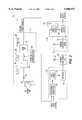
- FIG. 2is a schematic block diagram illustrating, in greater detail, the communication system of FIG. 1.
- FIG. 3is a schematic block diagram showing the phase select and compensation circuit of the present invention.
- an RF communication system 10 for wireless speakersis described.
- the system 10is capable of operating in the presence of a repetitive RF interference source powered from an Alternating Current (AC) power line 16.
- the interference sourceis the illustrated microwave oven 12.
- the microwave oven 12includes a power transformer 13, a diode 14 and a magnetron tube 15 powered from the AC power line 16.
- the microwave oven 12emits interference on a nominal frequency of 2.45 GHz., and in a pulsating manner with a repetition rate equal to that of the local AC power line period and at a 50% duty cycle. In the United States this corresponds to a nominal repetition rate of 1/60.
- the resulting RF interference to communication systems sharing the frequency bandis overcome by the system 10 in accordance with the present invention.
- the communication system 10 of the illustrated embodimentincludes a pair of receiver devices 20, and their respective antennas 21.
- the receiver devices 20are connected to respective audio loudspeakers 22 as will be readily appreciated by those skilled in the art.
- the receiver devices 20are also powered from the AC power line 16, although the interference is RF coupled to the receivers through the antennas 21.
- the communication system 10also includes a transmitter device 30 which, in turn, includes the illustrated power line sensor 31, data transmit controller 32, RF transmitter 33, and antenna 34.
- the transmitter device 30is connected to the audio signal source 35, which may be a digital audio signal source, such as a compact disk player, for example.
- the signal sourcemay also be an analog audio signal source that is processed into an appropriate digital format.
- the systemmay be used to transmit data files, digitized video, telephony signals, Internet data, etc., as will be readily understood by those skilled in the art.
- the communication system 10uses redundant transmission synchronized to the power line to ensure accurate reception by the receiver devices 20. More particularly, the microwave oven 12 has repetitive ON and OFF periods based upon tile AC power line, and the RF communication system 10 comprises the transmitter device 30 powered from the AC power line 16 which also powers the microwave oven.
- the transmitter device 30includes a power line sensor 31 for generating a series of packet frame trigger signals synchronized to the AC power line 16.
- the sensor 31illustratively includes an input transformer 41 and a diode connected in series with the secondary winding to generate the first half-wave rectified sinusoidal waveform 43. This signal is passed to the illustrated comparator 44 to produce the square wave signal waveform 46. The comparator 44, in turn, is connected to the edge detector 47 which generates the series of data packet frame triggers as shown in the waveform 48.
- the power line sensor 31functions as a zero crossing voltage detector which generates a plurality of trigger signals synchronized to the zero crossings of voltage of the AC power line 16.
- the data transmit controller or control means 32accepts as inputs the digital audio signals, and the packet frame triggers from the power line sensor 31.
- the data transmit controller 32includes a data packet generator 51 for digitizing the input data and assembling the digitized data into data packets. A cyclic redundancy check (CRC) coding is performed by the illustrated CRC block 52 as would be readily understood by those skilled in the art.
- CRCcyclic redundancy check
- the data transmit control means 32also operates the RF transmitter 33 to produce repetitive first and second transmissions of a same data packet using the schematically illustrated repeater circuit 53 based upon the packet frame trigger signals from the power line sensor 31. Accordingly, at least one of the first and second transmissions occurs during an OFF period of the repetitive RF interference from the operating microwave oven 12.
- the data packet generator 51 and CRC coder 52 of the data transmit control means 32preferably generate each data packet and error detecting portion to be less than or equal to one-half a period of the AC power line. Accordingly, no complicated data handling is needed for carryover to a next interval.
- the communication system 10is especially applicable to a communication system including only one way communication from the first device to at least one second device, such as for the illustrated remote audio speakers 22.
- the system 10 as shown in FIG. 2also includes a receiver device 20 illustrated in greater detail.
- the receiver device 20includes a spread spectrum RF receiver 57 which cooperates with the spread spectrum RF transmitter 33.
- spread spectrum communicationsmay also lessen the susceptibility of the communication link to other potential interference sources.
- Harris Corporationhas developed and offers chip sets for a WLAN under the marks PRISM I and PRISM II, which can be readily modified to provide the spread spectrum transmitter and receiver functions as would be appreciated by those skilled in the art.
- the receiver device 20also includes an error detecting circuit 58 and a packet select circuit 59 connected thereto. Accordingly, the receiver device 20 receives the redundantly transmitted first and second transmissions, and if the first packet is correct, it is kept, and if the packet is in error it is discarded and the second packet is used.
- the inventionprovides a relatively straightforward 1/2 forward error correcting retransmission approach for assuring correct operation in the present of the interference created by the microwave oven 12. No return channel is needed as in other more complicated approaches as have been attempted in the prior art, such as U.S. Pat. No. 5,574,979 to West.
- the power line sensor 31 portion of transmitter device 30further comprises phase selecting and compensating means 65 for selecting operation for one of the plurality of power phases.
- An indicator in the form of an LED 61may be provided at the receiver device 20 to indicate correct receipt of a data packet to thereby enable a user to select operation of the transmitter device 30 for one of the AC power line phases.
- a three-times multiplying phase locked loop (PLL) 66is locked to the line frequency to produce a 180 Hz square wave for a 60 Hz power line.
- Each phase of a conventional three phase power lineis offset from adjacent phases by a time interval equal to T/3, where T is the period of the power line, such as 16.7 msec for a 60 Hz power line.
- the circuitincludes three selectable configurations.
- a first configurationis set by a direct connection 70 between the ⁇ 3 PLL 66 and the divide by three circuit 67, as would be used if the transmitter device 30 and the microwave oven 12 were powered by the same phase.
- a second configurationis provided by the T/3 delay 71, and a third configuration is selected by the 2T/3 delay 72 as will be readily appreciated by those skilled in the art by stepping through operation for each phase.
- the illustrated manual switch 74may be used to set the device 30 to the desired phase operating configuration.
- a usercan set the desired configuration and the system 10 will operate properly, unless one of the transmitter device 30 or microwave oven 12 are reconnected to different power line phases.
- the usersets the desired configuration by turning on the microwave oven 12, stepping through the configurations using the switch 74, and observing the indicator 61 to determine which configuration produces successful communication.
- a method aspect of the inventionis for operating an RF communication system 10 in the presence of a repetitive RF interference source, such as a microwave oven 12, both powered from an AC power line, although the phases may be different.
- the methodpreferably comprises the steps of: sensing the AC power line 16; generating a plurality of data packets with each data packet including an error detecting portion, and for operating the RF transmitter 33 to produce repetitive first and second transmissions of a same data packet responsive to the AC power line so that at least one of the first and second transmissions occurs during an OFF period of the repetitive RF interference source; and receiving at the RF receiver device 20 the repetitive first and second transmissions of same data packets and selecting one based upon the error detecting portions thereof to thereby avoid interference from the repetitive RF interference source.
Landscapes
- Engineering & Computer Science (AREA)
- Computer Networks & Wireless Communication (AREA)
- Signal Processing (AREA)
- Mobile Radio Communication Systems (AREA)
- Noise Elimination (AREA)
Abstract
Description
Claims (40)
Priority Applications (7)
| Application Number | Priority Date | Filing Date | Title |
|---|---|---|---|
| US09/006,071US6006071A (en) | 1998-01-12 | 1998-01-12 | RF communications system operable in the presence of a repetitive interference source and related methods |
| ZA9811958AZA9811958B (en) | 1998-01-12 | 1998-12-30 | RF communications system operable in the presence of a repetitive interference source and related methods. |
| CA002258056ACA2258056A1 (en) | 1998-01-12 | 1998-12-30 | Rf communications system operable in the presence of a repetitive interference source and related methods |
| AU98261/98AAU9826198A (en) | 1998-01-12 | 1998-12-31 | RF communications system operable in the presence of a repetitive interference source and related methods |
| SG1999000032ASG72915A1 (en) | 1998-01-12 | 1999-01-08 | Rf communications system operable in the presence of a repetitive interference source and related methods |
| EP99300150AEP0935347A2 (en) | 1998-01-12 | 1999-01-08 | RF communications system operable in the presence of a repetitive interference source and related methods |
| CN99101061ACN1239849A (en) | 1998-01-12 | 1999-01-12 | RF communications system operable in presence of repetitive interference source and related methods |
Applications Claiming Priority (1)
| Application Number | Priority Date | Filing Date | Title |
|---|---|---|---|
| US09/006,071US6006071A (en) | 1998-01-12 | 1998-01-12 | RF communications system operable in the presence of a repetitive interference source and related methods |
Publications (1)
| Publication Number | Publication Date |
|---|---|
| US6006071Atrue US6006071A (en) | 1999-12-21 |
Family
ID=21719154
Family Applications (1)
| Application Number | Title | Priority Date | Filing Date |
|---|---|---|---|
| US09/006,071Expired - LifetimeUS6006071A (en) | 1998-01-12 | 1998-01-12 | RF communications system operable in the presence of a repetitive interference source and related methods |
Country Status (7)
| Country | Link |
|---|---|
| US (1) | US6006071A (en) |
| EP (1) | EP0935347A2 (en) |
| CN (1) | CN1239849A (en) |
| AU (1) | AU9826198A (en) |
| CA (1) | CA2258056A1 (en) |
| SG (1) | SG72915A1 (en) |
| ZA (1) | ZA9811958B (en) |
Cited By (25)
| Publication number | Priority date | Publication date | Assignee | Title |
|---|---|---|---|---|
| US6256478B1 (en)* | 1999-02-18 | 2001-07-03 | Eastman Kodak Company | Dynamic packet sizing in an RF communications system |
| US6346692B1 (en)* | 1999-09-20 | 2002-02-12 | Agere Systems Guardian Corp. | Adaptive microwave oven |
| US6349198B1 (en)* | 2000-01-25 | 2002-02-19 | Eastman Kodak Company | Wireless control system for periodic noise sources |
| US20020039888A1 (en)* | 2000-09-29 | 2002-04-04 | Seiko Epson Corporation | Wireless communication device |
| US6374082B1 (en)* | 1998-06-02 | 2002-04-16 | Eastman Kodak Company | RF wireless communication system operating in periodic noise environments |
| US20020086639A1 (en)* | 2000-12-28 | 2002-07-04 | Siemens Information And Communication Products, Inc. | Air interface frame structure for environments with bursted interference |
| US20040010746A1 (en)* | 2002-07-10 | 2004-01-15 | Lucas L. Victor | Forward error correction system for wireless communications |
| US6711380B1 (en) | 2000-05-25 | 2004-03-23 | Motorola, Inc. | Method and apparatus for reducing interference effects caused by microwave sources |
| WO2003100572A3 (en)* | 2002-05-24 | 2004-04-15 | Chrysalis Dev | Method and apparatus for detecting the presence of wireless network |
| US6760671B1 (en)* | 2002-04-09 | 2004-07-06 | Cisco Technology, Inc. | Method and apparatus of low power energy detection for a WLAN |
| US6804496B1 (en)* | 1999-02-05 | 2004-10-12 | Appairent Technologies, Inc. | Communicating in the presence of periodic microwave noise |
| US20050032516A1 (en)* | 2002-05-24 | 2005-02-10 | Bruno Marchevsky | Method and apparatus for detecting the presence of a wireless network |
| US20060068715A1 (en)* | 2004-09-30 | 2006-03-30 | Hundal Sukhdeep S | System and method for asymmetric enhanced mode operation in a digital communication system |
| US20060120333A1 (en)* | 2000-05-24 | 2006-06-08 | Dion Horvat | Method for avoiding interference in a digital communication system |
| US7072408B2 (en)* | 2001-02-20 | 2006-07-04 | Lucent Technologies Inc. | Method and system for using power lines for signaling, telephony and data communications |
| US20070086376A1 (en)* | 2001-12-05 | 2007-04-19 | Adaptix, Inc. | Wireless communication subsystem with a digital interface |
| US7308233B2 (en) | 2002-10-10 | 2007-12-11 | Aster Wireless | System employing wideband wireless communication with super cycle detection |
| US7369484B1 (en)* | 2001-04-26 | 2008-05-06 | Adaptix, Inc. | System and method for mitigating data flow control problems in the presence of certain interference parameters |
| US20080146156A1 (en)* | 2006-12-15 | 2008-06-19 | Motorola, Inc. | Method and system for predictive sensing of periodic intermittent interference |
| US20090086684A1 (en)* | 2007-10-02 | 2009-04-02 | Motorola, Inc. | Method for Preventing Co-Channel Operation with Radar Systems |
| US20110251806A1 (en)* | 2010-04-08 | 2011-10-13 | Ulrich Klapper | Method of monitoring a power transmission line and measuring device |
| US20120063518A1 (en)* | 2010-09-13 | 2012-03-15 | Honeywell International, Inc. | Devices, methods, and systems for building monitoring |
| US20120314785A1 (en)* | 2010-01-15 | 2012-12-13 | Sew-Eurodrive Gmbh & Co. Kg | Method for Data Transmission and Data Transmission System |
| US20200351787A1 (en)* | 2019-05-02 | 2020-11-05 | Mediatek Singapore Pte. Ltd. | Method And Apparatus For Avoiding Interference Between WiFi Operation And Microwave Oven Operation |
| US20240235594A9 (en)* | 2021-03-02 | 2024-07-11 | Sony Group Corporation | Noise canceling apparatus, noise canceling method, and electronic equipment |
Families Citing this family (6)
| Publication number | Priority date | Publication date | Assignee | Title |
|---|---|---|---|---|
| US6496498B1 (en)* | 1999-11-19 | 2002-12-17 | Siemens Information & Communication Mobile Llc | Method and system for avoiding periodic bursts of interference in wireless communication between a mobile unit and a base unit |
| WO2001065709A1 (en)* | 2000-03-01 | 2001-09-07 | Lake Communications Limited | Communications system robust against periodic interference |
| AU2001245913A1 (en)* | 2000-03-28 | 2001-10-08 | Telefonaktiebolaget Lm Ericsson (Publ) | Apparatus and methods for selective interference mitigation |
| KR20020082147A (en)* | 2001-04-23 | 2002-10-30 | 가부시끼가이샤 도시바 | Wireless communication apparatus and microwave oven cooperating with the same |
| US8787301B2 (en) | 2004-04-16 | 2014-07-22 | Dsp Group Switzerland Ag | Method and device for interference mitigation using redundant transmission in separate ISM bands |
| CN104298142A (en)* | 2014-10-10 | 2015-01-21 | 中国航天科技集团公司第四研究院第四十一研究所 | Anti-interference control circuit for launch control equipment |
Citations (15)
| Publication number | Priority date | Publication date | Assignee | Title |
|---|---|---|---|---|
| US4479033A (en)* | 1982-03-29 | 1984-10-23 | Astech, Inc. | Telephone extension system utilizing power line carrier signals |
| US4996484A (en)* | 1988-12-29 | 1991-02-26 | Atlantic Richfield Company | Method and apparatus for cancelling powerline noise in geophysical electromagnetic exploration |
| US5129003A (en)* | 1989-08-31 | 1992-07-07 | Kabushiki Kaisha Toshiba | Active noise control apparatus for domestic appliance |
| US5241687A (en)* | 1991-02-14 | 1993-08-31 | Bose Corporation | Phase controlling phase of local subcarrier signal to correspond to transmitted pilot signal |
| US5349700A (en)* | 1991-10-28 | 1994-09-20 | Bose Corporation | Antenna tuning system for operation over a predetermined frequency range |
| US5412658A (en)* | 1993-10-22 | 1995-05-02 | Bell Communications Research, Inc. | Beacon detection method and apparatus for sharing spectrum between wireless communications systems and fixed microwave systems |
| US5428669A (en)* | 1991-01-08 | 1995-06-27 | Thomson Consumer Electronics, Inc. | Automatic channel selection system for a cordless telephone |
| US5483693A (en)* | 1992-03-19 | 1996-01-09 | Bose Corporation | Combining antenna element signals |
| US5483689A (en)* | 1993-05-07 | 1996-01-09 | Bose Corporation | Radio receiving with microprocessor control |
| US5491839A (en)* | 1991-08-21 | 1996-02-13 | L. S. Research, Inc. | System for short range transmission of a plurality of signals simultaneously over the air using high frequency carriers |
| US5574979A (en)* | 1994-06-03 | 1996-11-12 | Norand Corporation | Periodic interference avoidance in a wireless radio frequency communication system |
| US5623531A (en)* | 1986-10-22 | 1997-04-22 | Nilssen; Ole K. | Auxiliary power for telephone distribution system |
| US5657325A (en)* | 1995-03-31 | 1997-08-12 | Lucent Technologies Inc. | Transmitter and method for transmitting information packets with incremental redundancy |
| US5812940A (en)* | 1994-04-21 | 1998-09-22 | Ericsson Inc. | Reducing interference from oscillators in electronic equipment |
| US5828293A (en)* | 1997-06-10 | 1998-10-27 | Northern Telecom Limited | Data transmission over a power line communications system |
- 1998
- 1998-01-12USUS09/006,071patent/US6006071A/ennot_activeExpired - Lifetime
- 1998-12-30ZAZA9811958Apatent/ZA9811958B/enunknown
- 1998-12-30CACA002258056Apatent/CA2258056A1/ennot_activeAbandoned
- 1998-12-31AUAU98261/98Apatent/AU9826198A/ennot_activeAbandoned
- 1999
- 1999-01-08EPEP99300150Apatent/EP0935347A2/ennot_activeWithdrawn
- 1999-01-08SGSG1999000032Apatent/SG72915A1/enunknown
- 1999-01-12CNCN99101061Apatent/CN1239849A/enactivePending
Patent Citations (15)
| Publication number | Priority date | Publication date | Assignee | Title |
|---|---|---|---|---|
| US4479033A (en)* | 1982-03-29 | 1984-10-23 | Astech, Inc. | Telephone extension system utilizing power line carrier signals |
| US5623531A (en)* | 1986-10-22 | 1997-04-22 | Nilssen; Ole K. | Auxiliary power for telephone distribution system |
| US4996484A (en)* | 1988-12-29 | 1991-02-26 | Atlantic Richfield Company | Method and apparatus for cancelling powerline noise in geophysical electromagnetic exploration |
| US5129003A (en)* | 1989-08-31 | 1992-07-07 | Kabushiki Kaisha Toshiba | Active noise control apparatus for domestic appliance |
| US5428669A (en)* | 1991-01-08 | 1995-06-27 | Thomson Consumer Electronics, Inc. | Automatic channel selection system for a cordless telephone |
| US5241687A (en)* | 1991-02-14 | 1993-08-31 | Bose Corporation | Phase controlling phase of local subcarrier signal to correspond to transmitted pilot signal |
| US5491839A (en)* | 1991-08-21 | 1996-02-13 | L. S. Research, Inc. | System for short range transmission of a plurality of signals simultaneously over the air using high frequency carriers |
| US5349700A (en)* | 1991-10-28 | 1994-09-20 | Bose Corporation | Antenna tuning system for operation over a predetermined frequency range |
| US5483693A (en)* | 1992-03-19 | 1996-01-09 | Bose Corporation | Combining antenna element signals |
| US5483689A (en)* | 1993-05-07 | 1996-01-09 | Bose Corporation | Radio receiving with microprocessor control |
| US5412658A (en)* | 1993-10-22 | 1995-05-02 | Bell Communications Research, Inc. | Beacon detection method and apparatus for sharing spectrum between wireless communications systems and fixed microwave systems |
| US5812940A (en)* | 1994-04-21 | 1998-09-22 | Ericsson Inc. | Reducing interference from oscillators in electronic equipment |
| US5574979A (en)* | 1994-06-03 | 1996-11-12 | Norand Corporation | Periodic interference avoidance in a wireless radio frequency communication system |
| US5657325A (en)* | 1995-03-31 | 1997-08-12 | Lucent Technologies Inc. | Transmitter and method for transmitting information packets with incremental redundancy |
| US5828293A (en)* | 1997-06-10 | 1998-10-27 | Northern Telecom Limited | Data transmission over a power line communications system |
Non-Patent Citations (2)
| Title |
|---|
| Jonathan Horne, et al., "Modeling and Mitigation of Interference in the 2.4 GHz ISM Band," Pub. 2.4 GHz Interference, Mar./Apr. 1997, pp. 59-71. |
| Jonathan Horne, et al., Modeling and Mitigation of Interference in the 2.4 GHz ISM Band, Pub. 2.4 GHz Interference, Mar./Apr. 1997, pp. 59 71.* |
Cited By (45)
| Publication number | Priority date | Publication date | Assignee | Title |
|---|---|---|---|---|
| US6374082B1 (en)* | 1998-06-02 | 2002-04-16 | Eastman Kodak Company | RF wireless communication system operating in periodic noise environments |
| US20050124298A1 (en)* | 1999-02-05 | 2005-06-09 | Appairent Technologies, Inc. | Communicating in the presence of periodic noise |
| US6804496B1 (en)* | 1999-02-05 | 2004-10-12 | Appairent Technologies, Inc. | Communicating in the presence of periodic microwave noise |
| US6256478B1 (en)* | 1999-02-18 | 2001-07-03 | Eastman Kodak Company | Dynamic packet sizing in an RF communications system |
| US6346692B1 (en)* | 1999-09-20 | 2002-02-12 | Agere Systems Guardian Corp. | Adaptive microwave oven |
| US6349198B1 (en)* | 2000-01-25 | 2002-02-19 | Eastman Kodak Company | Wireless control system for periodic noise sources |
| US20060120333A1 (en)* | 2000-05-24 | 2006-06-08 | Dion Horvat | Method for avoiding interference in a digital communication system |
| US8531998B2 (en) | 2000-05-24 | 2013-09-10 | Vtech Communications, Ltd. | Communications apparatus and method to avoid interference |
| US7990933B2 (en)* | 2000-05-24 | 2011-08-02 | Vtech Communications, Ltd. | Method for avoiding interference in a digital communication system |
| US6711380B1 (en) | 2000-05-25 | 2004-03-23 | Motorola, Inc. | Method and apparatus for reducing interference effects caused by microwave sources |
| US20020039888A1 (en)* | 2000-09-29 | 2002-04-04 | Seiko Epson Corporation | Wireless communication device |
| US20020086639A1 (en)* | 2000-12-28 | 2002-07-04 | Siemens Information And Communication Products, Inc. | Air interface frame structure for environments with bursted interference |
| US7072408B2 (en)* | 2001-02-20 | 2006-07-04 | Lucent Technologies Inc. | Method and system for using power lines for signaling, telephony and data communications |
| US7675840B1 (en) | 2001-04-26 | 2010-03-09 | Adaptix, Inc. | System and method for mitigating data flow control problems in the presence of certain interference parameters |
| US7369484B1 (en)* | 2001-04-26 | 2008-05-06 | Adaptix, Inc. | System and method for mitigating data flow control problems in the presence of certain interference parameters |
| US10469113B2 (en) | 2001-12-05 | 2019-11-05 | Netgear, Inc. | Wireless communication subsystem with a digital interface |
| US20100272163A1 (en)* | 2001-12-05 | 2010-10-28 | Adaptix, Inc. | Wireless communication subsystem with a digital interface |
| US8755395B2 (en) | 2001-12-05 | 2014-06-17 | Netgear, Inc | Wireless communication subsystem with a digital interface |
| US20070086376A1 (en)* | 2001-12-05 | 2007-04-19 | Adaptix, Inc. | Wireless communication subsystem with a digital interface |
| US9014200B2 (en) | 2001-12-05 | 2015-04-21 | Netgear, Inc. | Wireless communication subsystem with a digital interface |
| US7773614B1 (en) | 2001-12-05 | 2010-08-10 | Adaptix, Inc. | Wireless communication subsystem with a digital interface |
| US8345698B2 (en) | 2001-12-05 | 2013-01-01 | Netgear, Inc. | Wireless communication subsystem with a digital interface |
| US7472027B1 (en)* | 2002-04-09 | 2008-12-30 | Cisco Technology, Inc. | Method and apparatus of low power energy detection for a WLAN |
| US6760671B1 (en)* | 2002-04-09 | 2004-07-06 | Cisco Technology, Inc. | Method and apparatus of low power energy detection for a WLAN |
| US20040132446A1 (en)* | 2002-05-24 | 2004-07-08 | Michael Seedman | Method and apparatus for detecting the presence of a wireless network |
| US20050032516A1 (en)* | 2002-05-24 | 2005-02-10 | Bruno Marchevsky | Method and apparatus for detecting the presence of a wireless network |
| WO2003100572A3 (en)* | 2002-05-24 | 2004-04-15 | Chrysalis Dev | Method and apparatus for detecting the presence of wireless network |
| US7010298B2 (en) | 2002-05-24 | 2006-03-07 | Chrysalis California L.L.C. | Method and apparatus for detecting the presence of a wireless network |
| US20040010746A1 (en)* | 2002-07-10 | 2004-01-15 | Lucas L. Victor | Forward error correction system for wireless communications |
| US20080057870A1 (en)* | 2002-10-10 | 2008-03-06 | Aster Wireless | System employing wideband wireless communication with super cycle detection |
| US7308233B2 (en) | 2002-10-10 | 2007-12-11 | Aster Wireless | System employing wideband wireless communication with super cycle detection |
| US7693488B2 (en) | 2004-09-30 | 2010-04-06 | Vtech Telecommunications Limited | System and method for asymmetric enhanced mode operation in a digital communication system |
| US20060068715A1 (en)* | 2004-09-30 | 2006-03-30 | Hundal Sukhdeep S | System and method for asymmetric enhanced mode operation in a digital communication system |
| US20080146156A1 (en)* | 2006-12-15 | 2008-06-19 | Motorola, Inc. | Method and system for predictive sensing of periodic intermittent interference |
| US8050627B2 (en)* | 2006-12-15 | 2011-11-01 | Motorola Mobility, Inc. | Method and system for predictive sensing of periodic intermittent interference |
| US8179862B2 (en) | 2007-10-02 | 2012-05-15 | Motorola Mobility, Inc. | Method for preventing co-channel operation with radar systems |
| US20090086684A1 (en)* | 2007-10-02 | 2009-04-02 | Motorola, Inc. | Method for Preventing Co-Channel Operation with Radar Systems |
| US20120314785A1 (en)* | 2010-01-15 | 2012-12-13 | Sew-Eurodrive Gmbh & Co. Kg | Method for Data Transmission and Data Transmission System |
| US20110251806A1 (en)* | 2010-04-08 | 2011-10-13 | Ulrich Klapper | Method of monitoring a power transmission line and measuring device |
| US9455767B2 (en)* | 2010-04-08 | 2016-09-27 | Omicron Electronics Gmbh | Method of monitoring a power transmission line and measuring device |
| US8457179B2 (en)* | 2010-09-13 | 2013-06-04 | Honeywell International Inc. | Devices, methods, and systems for building monitoring |
| US20120063518A1 (en)* | 2010-09-13 | 2012-03-15 | Honeywell International, Inc. | Devices, methods, and systems for building monitoring |
| US20200351787A1 (en)* | 2019-05-02 | 2020-11-05 | Mediatek Singapore Pte. Ltd. | Method And Apparatus For Avoiding Interference Between WiFi Operation And Microwave Oven Operation |
| US10869274B2 (en)* | 2019-05-02 | 2020-12-15 | Mediatek Singapore Pte. Ltd. | Method and apparatus for avoiding interference between WiFi operation and microwave oven operation |
| US20240235594A9 (en)* | 2021-03-02 | 2024-07-11 | Sony Group Corporation | Noise canceling apparatus, noise canceling method, and electronic equipment |
Also Published As
| Publication number | Publication date |
|---|---|
| SG72915A1 (en) | 2000-05-23 |
| CN1239849A (en) | 1999-12-29 |
| EP0935347A2 (en) | 1999-08-11 |
| AU9826198A (en) | 1999-07-29 |
| CA2258056A1 (en) | 1999-07-12 |
| ZA9811958B (en) | 2000-02-01 |
Similar Documents
| Publication | Publication Date | Title |
|---|---|---|
| US6006071A (en) | RF communications system operable in the presence of a repetitive interference source and related methods | |
| US6011784A (en) | Communication system and method using asynchronous and isochronous spectrum for voice and data | |
| US6711380B1 (en) | Method and apparatus for reducing interference effects caused by microwave sources | |
| US20060193271A1 (en) | Physical layer repeater configuration for increasing MIMO performance | |
| JP2009050007A (en) | Wireless communication apparatus and wireless communication method | |
| US12289636B2 (en) | Collision detection method | |
| JP2004320739A (en) | Uplink / downlink synchronization device for mobile communication terminal | |
| JP2004080165A (en) | Receiving device, transmitting device and communication method | |
| US6034990A (en) | Digital radio transmission and reception system applying a direct modulation and demodulation method | |
| WO2008044510A1 (en) | Communication device and communication system | |
| MXPA02003541A (en) | Method and apparatus for minimising total transmission energy in a communication system by using channel quality. | |
| EP2086273A2 (en) | Communication apparatus and method for controlling communication channel used | |
| CN105554809A (en) | Wireless communication device and method for controlling wireless communication device | |
| KR20050110267A (en) | Method for acquiring syncronization in relay of time division duplexing procedure and apparatus | |
| JPH09200107A (en) | Mobile communication system in common use for indoor and outdoor | |
| EP1253753A2 (en) | Wireless communication apparatus and microwave oven cooperating with the same | |
| JP2007158976A (en) | Apparatus, program, and method for communication | |
| JP7333034B2 (en) | Wireless RF transmission method and wireless RF receiver | |
| JP2005012411A (en) | Wireless communication device | |
| JP3091703B2 (en) | Frequency hopping spread spectrum communication system | |
| EP1003293A1 (en) | Process for synchronizing at least two time bases each belonging to a base station and base station thus synchronized | |
| KR100655335B1 (en) | RF Input Signal Level Adjuster | |
| JPH02276322A (en) | Automatic inter-station phase compensating system | |
| JP3218803B2 (en) | Cordless telephone | |
| JP2865101B1 (en) | Receiver |
Legal Events
| Date | Code | Title | Description |
|---|---|---|---|
| AS | Assignment | Owner name:HARRIS CORPORATION, FLORIDA Free format text:ASSIGNMENT OF ASSIGNORS INTEREST;ASSIGNORS:ROBERTS, RICHARD D.;NELSON, GEORGE R.;REEL/FRAME:008927/0186 Effective date:19980109 | |
| AS | Assignment | Owner name:INTERSIL CORPORATION, FLORIDA Free format text:AMEND TO ADD PROPERTIES RECORDED ON REEL 10247, FRAME 0043.;ASSIGNOR:HARRIS CORPORATION;REEL/FRAME:010884/0394 Effective date:19990813 | |
| AS | Assignment | Owner name:CREDIT SUISSE FIRST BOSTON, AS COLLATERAL AGENT, N Free format text:SECURITY INTEREST;ASSIGNOR:INTERSIL CORPORATION;REEL/FRAME:010351/0410 Effective date:19990813 | |
| STCF | Information on status: patent grant | Free format text:PATENTED CASE | |
| CC | Certificate of correction | ||
| FEPP | Fee payment procedure | Free format text:PAYOR NUMBER ASSIGNED (ORIGINAL EVENT CODE: ASPN); ENTITY STATUS OF PATENT OWNER: LARGE ENTITY | |
| FPAY | Fee payment | Year of fee payment:4 | |
| FPAY | Fee payment | Year of fee payment:8 | |
| AS | Assignment | Owner name:MORGAN STANLEY & CO. INCORPORATED,NEW YORK Free format text:SECURITY AGREEMENT;ASSIGNORS:INTERSIL CORPORATION;TECHWELL, INC.;INTERSIL COMMUNICATIONS, INC.;AND OTHERS;REEL/FRAME:024329/0831 Effective date:20100427 | |
| FPAY | Fee payment | Year of fee payment:12 | |
| AS | Assignment | Owner name:INTERSIL COMMUNICATIONS, INC., CALIFORNIA Free format text:CHANGE OF NAME;ASSIGNOR:INTERSIL CORPORATION;REEL/FRAME:033261/0088 Effective date:20010523 Owner name:INTERSIL AMERICAS LLC, CALIFORNIA Free format text:CHANGE OF NAME;ASSIGNOR:INTERSIL AMERICAS INC.;REEL/FRAME:033262/0819 Effective date:20111223 Owner name:INTERSIL AMERICAS INC., CALIFORNIA Free format text:ASSIGNMENT OF ASSIGNORS INTEREST;ASSIGNOR:INTERSIL COMMUNICATIONS, INC.;REEL/FRAME:033262/0582 Effective date:20011221 |