US6005955A - Middle ear transducer - Google Patents
Middle ear transducerDownload PDFInfo
- Publication number
- US6005955A US6005955AUS08/693,436US69343696AUS6005955AUS 6005955 AUS6005955 AUS 6005955AUS 69343696 AUS69343696 AUS 69343696AUS 6005955 AUS6005955 AUS 6005955A
- Authority
- US
- United States
- Prior art keywords
- transducer
- carrier
- transducers
- auditory
- middle ear
- Prior art date
- Legal status (The legal status is an assumption and is not a legal conclusion. Google has not performed a legal analysis and makes no representation as to the accuracy of the status listed.)
- Expired - Lifetime
Links
Images


Classifications
- H—ELECTRICITY
- H04—ELECTRIC COMMUNICATION TECHNIQUE
- H04R—LOUDSPEAKERS, MICROPHONES, GRAMOPHONE PICK-UPS OR LIKE ACOUSTIC ELECTROMECHANICAL TRANSDUCERS; DEAF-AID SETS; PUBLIC ADDRESS SYSTEMS
- H04R25/00—Deaf-aid sets, i.e. electro-acoustic or electro-mechanical hearing aids; Electric tinnitus maskers providing an auditory perception
- H04R25/60—Mounting or interconnection of hearing aid parts, e.g. inside tips, housings or to ossicles
- H04R25/604—Mounting or interconnection of hearing aid parts, e.g. inside tips, housings or to ossicles of acoustic or vibrational transducers
- H04R25/606—Mounting or interconnection of hearing aid parts, e.g. inside tips, housings or to ossicles of acoustic or vibrational transducers acting directly on the eardrum, the ossicles or the skull, e.g. mastoid, tooth, maxillary or mandibular bone, or mechanically stimulating the cochlea, e.g. at the oval window
- A—HUMAN NECESSITIES
- A61—MEDICAL OR VETERINARY SCIENCE; HYGIENE
- A61F—FILTERS IMPLANTABLE INTO BLOOD VESSELS; PROSTHESES; DEVICES PROVIDING PATENCY TO, OR PREVENTING COLLAPSING OF, TUBULAR STRUCTURES OF THE BODY, e.g. STENTS; ORTHOPAEDIC, NURSING OR CONTRACEPTIVE DEVICES; FOMENTATION; TREATMENT OR PROTECTION OF EYES OR EARS; BANDAGES, DRESSINGS OR ABSORBENT PADS; FIRST-AID KITS
- A61F2/00—Filters implantable into blood vessels; Prostheses, i.e. artificial substitutes or replacements for parts of the body; Appliances for connecting them with the body; Devices providing patency to, or preventing collapsing of, tubular structures of the body, e.g. stents
- A61F2/02—Prostheses implantable into the body
- A61F2/18—Internal ear or nose parts, e.g. ear-drums
- A61F2002/183—Ear parts
Definitions
- This inventionrelates to an electromechanical transducer for use in a hearing system at least partially implantable in a middle ear.
- soundsproduce mechanical vibrations which are transduced by an electromechanical input transducer into electrical signals. These electrical signals are in turn amplified and applied to an electromechanical output transducer.
- the electromechanical output transducervibrates an ossicular bone in response to the applied amplified electrical signals to improve hearing.
- Such electromechanical input and output transducersshould be proportioned to provide convenient implantation in the middle ear.
- Low power consumption transducersare also desired for use with a limited longevity implanted battery as a power source, such as for T-MEI hearing aid systems.
- the inventionprovides an electromechanical transducer for an implantable hearing aid, such as a partial middle ear implantable (P-MEI) or total middle ear implantable (T-MEI) hearing aid system.
- the transducercomprises a piezoelectric element proportioned for mechanical coupling to a middle ear only through an auditory element in the middle ear.
- the inventionprovides convenient piezoelectric input and output electromechanical transducers, each mounted only to the auditory element for which vibrations are transduced.
- the inventiondoes not require mounting a transducer to the temporal bone. This minimizes the invasive complexity of the surgical implantation procedure, and also minimizes steady state forces applied to the auditory element.
- an electromechanical input transduceris coupled only to a vibrating auditory element, such as a tympanic membrane, malleus, or incus.
- the vibrating auditory elementis optionally mechanically isolated from an auditory element vibrated by an electromechanical output transducer.
- an electromechanical output transduceris coupled only to a vibrated auditory element, such as an incus, stapes, oval window, round window, vestibule, or semicircular canal.
- Piezoelectric elements used in the electromechanical input and output transducerscomprise ceramic piezoelectric single element transducers, ceramic piezoelectric bi-element transducers, piezoelectric stacked transducers comprising multiple mechanically stacked subelements, piezoelectric film transducers, and piezoelectric film bi-element transducers.
- Certain embodimentsinclude an inertial mass used in conjunction with the piezoelectric elements for transducing between electrical signals and mechanical vibrations.
- An overall electrical-to-mechanical or mechanical-to-electrical frequency responseis optimized by superpositioning substantially nonidentical frequency responses of piezoelectric elements in combination with any accompanying inertial masses. Different frequency responses are obtained by using different masses, different piezoelectric elements, or other techniques.
- a carrieris provided to support the piezoelectric elements and any accompanying inertial masses.
- the carrieris secured only to the auditory element for which vibrations are transduced.
- the carrieris optionally hermetically sealed to protect the piezoelectric elements and inertial masses.
- the inventionprovides convenient piezoelectric input and output electromechanical transducers, each mounted only to the auditory element for which vibrations are transduced.
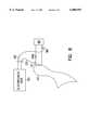
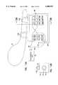
- FIG. 1illustrates a frontal section of an anatomically normal human right ear.
- FIG. 2is a cross-sectional illustration of a typical use of a bi-element transducer coupled to an auditory element in the middle ear.
- FIG. 3is a cross-sectional illustration of a first embodiment of the invention, including a bi-element transducer secured only to a vibrated auditory element.
- FIG. 4is a cross-sectional illustration of a second embodiment of the invention, including a bi-element transducer secured only to a vibrating auditory element.
- FIG. 5is a cross-sectional illustration of a third embodiment of the invention, using a single element transducer secured only to a vibrated auditory element.
- FIG. 6is a cross-sectional illustration of a fourth embodiment of the invention, using a single element transducer secured only to a vibrating auditory element.
- FIG. 7is a cross-sectional illustration of a fifth embodiment of the invention, including a carrier and also including an inertial mass interposed between two single element transducers.
- FIG. 8Ais a cross-sectional illustration of a sixth embodiment of the invention, including a carrier, a bi-element transducer, and an inertial mass.
- FIG. 8Bis a cross-sectional illustration of a further embodiment of the invention, including a carrier that does not enclose the bi-element transducer and inertial mass.
- FIG. 9is a cross-sectional illustration of a seventh embodiment of the invention, including a carrier and also including an inertial mass secured between two bi-element transducers.
- FIG. 10is a cross-sectional illustration of an eighth embodiment of the invention, including a carrier, two bi-element transducers, and two inertial masses.
- FIG. 11Ais a cross-sectional illustration of a ninth embodiment of the invention, including a carrier, two stacked transducers, and two inertial masses.
- FIG. 11Bis a cross-sectional illustration of an alternative embodiment, to FIG. 11A, having electrical connections across a length of each transducer subelement.
- FIG. 12Ais a cross-sectional illustration of a tenth embodiment of the invention, including a carrier and also including two stacked transducers secured within its opposing faces.
- FIG. 12Bis a cross-sectional illustration of an alternative embodiment, to FIG. 12A, having electrical connections across a length of each transducer subelement.
- FIG. 13Ais a cross-sectional illustration of an eleventh embodiment of the invention, including a carrier and also including two stacked transducers having cylindrically hollowed cores.
- FIG. 13Bis a cross-sectional view taken along the cut line illustrated in FIG. 13A.
- FIG. 14is a cross-sectional view of a twelfth embodiment of the invention, including a carrier and also including two single element transducers having cylindrically hollowed cores.
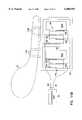
- FIG. 15is a cross-sectional view of a thirteenth embodiment of the invention, secured to a vibrating malleus, including a carrier, a film transducer, and an inertial mass.
- FIG. 16is a cross-sectional view of a fourteenth embodiment of the invention, secured to a vibrating incus, including a carrier and a plurality of film transducers and respective inertial masses.
- FIG. 17is a cross-sectional view of a fifteenth embodiment of the invention, secured to a vibrating malleus, including a carrier and also including a stacked transducer having a cylindrically hollowed core.
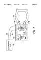
- FIG. 18is a cross-sectional view of the sixteenth embodiment of the invention, in use with a P-MEI hearing aid having a microphone in the external auditory canal.
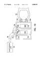
- FIG. 19is a cross-sectional view of a preferred embodiment of the invention, in use with a T-MEI hearing aid, including both electromechanical input and output transducers.
- the inventionprovides an electromechanical transducer which is particularly advantageous when used in a middle ear implantable hearing aid system such as a partial middle ear implantable (P-MEI), total middle ear implantable (T-MEI), or other hearing aid system.
- a P-MEI or T-MEI hearing aid systemassists the human auditory system in converting acoustic energy contained within sound waves into electrochemical signals delivered to the brain and interpreted as sound.
- FIG. 1illustrates generally the use of the invention in a human auditory system. Sound waves are directed into an external auditory canal 20 by an outer ear (pinna) 25. The frequency characteristics of the sound waves are slightly modified by the resonant characteristics of the external auditory canal 20.
- tympanic membraneeardrum
- tympanic cavitytympanic cavity
- Variations in the sound wavesproduce tympanic vibrations.
- the mechanical energy of the tympanic vibrationsis communicated to the inner ear, comprising cochlea 60, vestibule 61, and semicircular canals 62, by a sequence of articulating bones located in the middle ear 35.
- This sequence of articulating bonesis referred to generally as the ossicular chain 37.
- the ossicular chaintransforms acoustic energy at the eardrum to mechanical energy at the cochlea 60.
- the ossicular chain 37includes three primary components: a malleus 40, an incus 45, and a stapes 50.
- the malleus 40includes manubrium and head portions. The manubrium of the malleus 40 attaches to the tympanic membrane 30. The head of the malleus 40 articulates with one end of the incus 45. The incus 45 normally couples mechanical energy from the vibrating malleus 40 to the stapes 50.
- the stapes 50includes a capitulum portion, comprising a head and a neck, connected to a footplate portion by means of a support crus comprising two crura. The stapes 50 is disposed in and against a membrane-covered opening on the cochlea 60.
- This membrane-covered opening between the cochlea 60 and middle ear 35is referred to as the oval window 55.
- Oval window 55is considered part of cochlea 60 in this patent application.
- the incus 45articulates the capitulum of the stapes 50 to complete the mechanical transmission path.
- tympanic vibrationsare mechanically conducted through the malleus 40, incus 45, and stapes 50, to the oval window 55. Vibrations at the oval window 55 are conducted into the fluid-filled cochlea 60. These mechanical vibrations generate fluidic motion, thereby transmitting hydraulic energy within the cochlea 60. Pressures generated in the cochlea 60 by fluidic motion are accommodated by a second membrane-covered opening on the cochlea 60. This second membrane-covered opening between the cochlea 60 and middle ear 35 is referred to as the round window 65. Round window 65 is considered part of cochlea 60 in this patent application.
- Receptor cells in the cochlea 60translate the fluidic motion into neural impulses which are transmitted to the brain and perceived as sound.
- various disorders of the tympanic membrane 30, ossicular chain 37, and/or cochlea 60can disrupt or impair normal hearing.
- Hearing loss due to damage in the cochleais referred to as sensorineural hearing loss.
- Hearing loss due to an inability to conduct mechanical vibrations through the middle earis referred to as conductive hearing loss.
- Some patientshave an ossicular chain 37 lacking sufficient resiliency to transmit mechanical vibrations between the tympanic membrane 30 and the oval window 55. As a result, fluidic motion in the cochlea 60 is attenuated. Thus, receptor cells in the cochlea 60 do not receive adequate mechanical stimulation. Damaged elements of ossicular chain 37 may also interrupt transmission of mechanical vibrations between the tympanic membrane 30 and the oval window 55.
- tympanoplastyis used to surgically reconstruct the tympanic membrane 30 and establish ossicular continuity from the tympanic membrane 30 to the oval window 55.
- Various passive mechanical prostheses and implantation techniqueshave been developed in connection with reconstructive surgery of the middle ear 35 for patients with damaged elements of ossicular chain 37.
- Two basic forms of prosthesisare available: total ossicular replacement prostheses (TORP), which is connected between the tympanic membrane 30 and the oval window 55; and partial ossicular replacement prostheses (PORP), which is positioned between the tympanic membrane 30 and the stapes 50.
- TORPtotal ossicular replacement prostheses
- PORPpartial ossicular replacement prostheses
- a conventional "air conduction" hearing aidis sometimes used to overcome hearing loss due to sensorineural cochlear damage or mild conductive impediments to the ossicular chain 37.
- Conventional hearing aidsutilize a microphone, which transduces sound into an electrical signal.
- Amplification circuitryamplifies the electrical signal.
- a speakertransduces the amplified electrical signal into acoustic energy transmitted to the tympanic membrane 30.
- some of the transmitted acoustic energyis typically detected by the microphone, resulting in a feedback signal which degrades sound quality.
- Conventional hearing aidsalso often suffer from a significant amount of signal distortion.
- cochlear implant techniquesimplement an inner ear hearing aid system.
- Cochlear implantselectrically stimulate auditory nerve fibers within the cochlea 60.
- a typical cochlear implant systemincludes an external microphone, an external signal processor, and an external transmitter, as well as an implanted receiver and an implanted single channel or multichannel probe.
- a single channel probehas one electrode.
- a multichannel probehas an array of several electrodes.
- a signal processorconverts speech signals transduced by the microphone into a series of sequential electrical pulses corresponding to different frequency bands within a speech frequency spectrum.
- Electrical pulses corresponding to low frequency soundsare delivered to electrodes that are more apical in the cochlea 60.
- Electrical pulses corresponding to high frequency soundsare delivered to electrodes that are more basal in the cochlea 60.
- the nerve fibers stimulated by the electrodes of the cochlear implant probetransmit neural impulses to the brain, where these neural impulses are interpreted as sound.
- temporal bone conduction hearing aid systemsproduce mechanical vibrations that are coupled to the cochlea 60 via a temporal bone in the skull.
- a vibrating elementcan be implemented percutaneously or subcutaneously.
- a particularly interesting class of hearing aid systemsincludes those which are configured for disposition principally within the middle ear 35 space.
- an electrical-to-mechanical output transducercouples mechanical vibrations to the ossicular chain 37, which is optionally interrupted to allow coupling of the mechanical vibrations to the ossicular chain 37.
- Both electromagnetic and piezoelectric output transducershave been used to effect the mechanical vibrations upon the ossicular chain 37.
- One example of a partial middle ear implantable (P-MEI) hearing aid system having an electromagnetic output transducercomprises: an external microphone transducing sound into electrical signals; external amplification and modulation circuitry; and an external radio frequency (RF) transmitter for transdermal RF communication of an electrical signal.
- An implanted receiverdetects and rectifies the transmitted signal, driving an implanted coil in constant current mode.
- a resulting magnetic field from the implanted drive coilvibrates an implanted magnet that is permanently affixed only to the incus 45.
- Such electromagnetic output transducershave relatively high power consumption, which limits their usefulness in total middle ear implantable (T-MEI) hearing aid systems.
- a piezoelectric output transduceris also capable of effecting mechanical vibrations to the ossicular chain 37.
- An example of such a deviceis disclosed in U.S. Pat. No. 4,729,366, issued to D. W. Schaefer on Mar. 8, 1988.
- a mechanical-to-electrical piezoelectric input transduceris associated with the malleus 40, transducing mechanical energy into an electrical signal, which is amplified and further processed.
- a resulting electrical signalis provided to an electrical-to-mechanical piezoelectric output transducer that generates a mechanical vibration coupled to an element of the ossicular chain 37 or to the oval window 55 or round window 65.
- the ossicular chain 37is interrupted by removal of the incus 45. Removal of the incus 45 prevents the mechanical vibrations delivered by the piezoelectric output transducer from mechanically feeding back to the piezoelectric input transducer.
- Piezoelectric output transducershave several advantages over electromagnetic output transducers.
- the smaller size or volume of the piezoelectric output transduceradvantageously eases implantation into the middle ear 35.
- the lower power consumption of the piezoelectric output transduceris particularly attractive for T-MEI hearing aid systems, which include a limited longevity implanted battery as a power source.
- a piezoelectric output transduceris typically implemented as a ceramic piezo electric bi-element transducer, which is a cantilevered double plate ceramic element in which two opposing plates are bonded together such that they amplify a piezo electric action in a direction normal to the bonding plane.
- Such a bi-element transducervibrates according to a potential difference applied between two bonded plates.
- a proximal end of such a bi-element transduceris typically cantilevered from a transducer mount which is secured to a temporal bone within the middle ear.
- a distal end of such a bi-element transducercouples mechanical vibrations to an ossicular element such as stapes 50.
- securing a bi-element transducer mount to the temporal boneadds invasive complexity to the surgical implantation procedure.
- FIG. 2is a generalized illustration of a bi-element transducer 70 cantilevered at its proximal end from a mount 75 secured to a temporal bone within middle ear 35.
- a distal end of bi-element transducer 70is mechanically coupled to an auditory element to receive or effect mechanical vibrations when operating as an input or output transducer respectively.
- bi-element transducer 70may be coupled to an auditory element such as tympanic membrane 30, malleus 40, or incus 45.
- bi-element transducer 70may be coupled to an auditory element such as incus 45, stapes 50, oval window 55 , round window 65, vestibule 61, or semicircular canal 62.
- an auditory elementsuch as incus 45, stapes 50, oval window 55 , round window 65, vestibule 61, or semicircular canal 62.
- mounting bi-element transducer 70 to the temporal boneadds invasive complexity in its surgical implantation.
- the inventionprovides convenient piezoelectric input and output electromechanical transducers, each mounted only to the auditory element for which vibrations are transduced.
- the inventiondoes not require mounting a transducer to the temporal bone. This minimizes the invasive complexity of the surgical implantation procedure, and also minimizes steady state forces applied to the auditory element.
- FIG. 3illustrates generally a cross-sectional view of a first embodiment of the invention used as an electromechanical output transducer.
- a piezoelectric element, more particularly bi-element transducer 70is mechanically coupled, and preferably secured, at its proximal end to middle ear 35 only through an auditory element, preferably stapes 50, or alternatively incus 45, stapes 50, oval window 55, round window 65, vestibule 61, or semicircular canals 62.
- Bi-element transducer 70is secured only to stapes 50 by any known attachment technique, including biocompatible adhesives or mechanical fasteners.
- a deformable wire secured to the proximal end of bi-element transducer 70is looped through an inner portion of stapes 50 and crimped to secure bi-element transducer 70 to stapes 50.
- the exact technique of attachment to the auditory elementis not part of the invention, except that the piezoelectric element should be coupled only to the vibrated auditory element; it need not be secured elsewhere within the middle ear 35 such as to the temporal bone.
- inertial mass 80is secured to a distal end of bi-element transducer 70 by any known attachment technique, including a biocompatible adhesive or mechanical fastener.
- Inertial mass 80is of a biocompatible material such as titanium or stainless steel, or any other biocompatible material proportioned to provide sufficient inertial mass to impart a force upon stapes 50, as explained below.
- Electronics unit 95couples an electrical signal through lead wires 85 and 90 to any convenient respective connection points 86 and 91 on respective opposing elements of bi-element transducer 70.
- Electronics unit 95 and lead wires 85 and 90are not part of the invention, but rather show how the invention is used in conjunction with a P-MEI, T-MEI, or other hearing aid system.
- bi-element transducer 70bends with respect to a longitudinal plane between its opposing elements. The bending is resisted by inertial mass 80, thus mechanically coupling a force to stapes 50 through bi-element transducer 70. This force upon stapes 50 is in turn transmitted to cochlea 60 at oval window 55.
- FIG. 4illustrates generally a cross-sectional view of a second embodiment of the invention used as an electromechanical input transducer.
- a piezoelectric elementsuch as bi-element transducer 70
- Bi-element transducer 70is secured by any known attachment technique at its proximal end, such as described above, only to malleus 40.
- Bi-element transducer 70may also be secured only to other auditory elements for receiving mechanical vibrations, such as incus 45 or tympanic membrane 30. Vibrations of malleus 40 cause, at the proximal end of bi-element transducer 70, vibratory displacements that are opposed by inertial mass 80.
- bi-element transducer 70bends with respect to the longitudinal plane between its opposing elements.
- a resulting electrical signalis provided at any convenient connection points 86 and 91 on respective opposing elements of bi-element transducer 70, through respective lead wires 92 and 93 to electronics unit 95.
- FIG. 5illustrates generally a cross-sectional view of a third embodiment of the invention, used as an electromechanical output transducer, as described above.
- a piezoelectric elementsuch as ceramic single element transducer 100 is secured at its proximal end only to an auditory element, such as stapes 50. Any known attachment technique may be used, such as described above.
- An inertial mass 80, described above,is secured to a distal end of single element transducer 100 by any known attachment technique, such as described above.
- This embodimentuses a piezoelectric effect with displacement approximately orthogonal to the direction of an applied electrical input signal, although a piezoelectric effect in another direction may also be used at the designer's discretion by rearranging the connection points accordingly.
- Electronics unit 95delivers an electrical signal through lead wires 85 and 90 to any convenient respective connection points 86 and 91 on respective opposing faces of single element transducer 100.
- single element transducer 100expands and contracts in a longitudinal direction between its proximal and distal ends. This vibratory displacement is resisted by inertial mass 80, thus coupling a force to stapes 50 through single element transducer 100.
- 5comprises a stack of multiple piezoelectric subelements connected mechanically in series, and wired electrically in parallel for increased vibratory displacement.
- inertial mass 80is omitted; the distributed mass of transducer 100 mechanically couples a vibratory force to stapes 50.
- FIG. 6illustrates generally a cross-sectional view of a fourth embodiment of the invention, used as an electromechanical input transducer, as described above.
- Single element transducer 100is secured at its proximal end by any known attachment technique, such as described above, only to malleus 40 or other vibrating auditory element as described above. Vibrations at the proximal end of transducer 100 are opposed by inertial mass 80, longitudinally exerting forces on transducer 100.
- a resulting electrical signalis provided at any convenient connection points 86 and 91, on respective opposing faces of single element transducer 100, through respective lead wires 92 and 93 to electronics unit 95.
- FIG. 7illustrates generally a cross-sectional view of a fifth embodiment of the invention, used as an electromechanical output transducer, as described above.
- a proximal portion of a carrier 105is secured only to an auditory element, such as stapes 50, by any known attachment technique, as described above.
- deformable wires 110A-B, secured to carrier 105may looped through an inner portion of stapes 50 and crimped to secure carrier 105 to stapes 50.
- the exact technique of attachmentis not part of the present invention, except that carrier 105 should be coupled only to the auditory element; it need not be secured elsewhere within the middle ear 35 such as to the temporal bone.
- Carrier 105has opposing interior faces, between which are interposed first and second single element transducers 100A-B, which are respectively mechanically coupled to a distal and a proximal interior face of carrier 105.
- Inertial mass 80is interposed between and mechanically coupled to single element transducers 100A-B.
- This embodimentuses a piezoelectric effect with displacement approximately orthogonal to the direction of an applied electrical input signal, although a piezoelectric effect in another direction may also be used at the designer's discretion by rearranging the connection points accordingly.
- Electronics unit 95couples an electrical signal through lead wires 85 and 90 to connection points 86A-B and 91A-B. Connection points 86A-B and 91A-B are pairwise located wherever convenient on opposing faces of first and second single element transducers 100A-B, as illustrated in FIG. 7.
- First and second single element transducers 100A-Breceive opposite polarity electrical signals from electronics unit 95.
- lead wire 85is coupled at connection point 86B to a top face of single element transducer 100B and at connection point 86A to a bottom face of single element transducer 100A.
- lead wire 90is coupled at connection point 91B to a bottom face of single element transducer 100B and at connection point 91 A to a top face of single element transducer 100A.
- single element transducer 100Aexpands longitudinally while single element transducer 100B contracts longitudinally.
- single element transducer 100Acontracts longitudinally while single element transducer 100B expands longitudinally.
- single element transducers 100A-Bundergo opposite longitudinal deformations in concert to vibrate inertial mass 80. Vibration of inertial mass 80 results in a corresponding opposing vibration of carrier 105 and stapes 50, each of which are mechanically coupled to inertial mass 80.
- Carrier 105is proportioned for disposition within middle ear 35, and is constructed from any known biocompatible material, such as titanium. Carrier 105 is optionally hermetically sealed to protect any enclosed transducer elements and inertial mass from humidity and bodily fluids, providing feedthroughs for lead wires, such as lead wires 85 and 90, for coupling electrical signals through the hermetically sealed enclosure.
- FIG. 8Aillustrates generally a cross-sectional view of a sixth embodiment of the invention, used as an electromechanical output transducer, as described above.
- Bi-element transducer 70is interposed between opposing interior faces of carrier 105.
- Bi-element transducer 70is secured to opposing interior faces of carrier 105, such as at points 115 and 120, by any known attachment technique, including adhesives, mechanical fasteners, conforming or interlocking receptacles on carrier 105, or any other such attachment technique.
- Inertial mass 80is secured to one of the opposing elements of bi-element transducer 70 by an adhesive, or by any other attachment technique.
- Electronics unit 95couples an electrical signal through lead wires 85 and 90 to respective connection points 86 and 91 located wherever convenient on respective opposing elements of bi-element transducer 70.
- bi-element transducer 70bends with respect to a longitudinal plane between its opposing elements. The bending is opposed by inertial mass 80, thus mechanically coupling a vibratory force to stapes 50, which is in turn transmitted to cochlea 60 at oval window 55.
- FIG. 8Billustrates generally a cross-sectional view of a further embodiment in which carrier 105 provides support to bi-element transducer 70, but does not hermetically seal or otherwise enclose bi-element transducer 70 or inertial mass 80.
- FIG. 9illustrates generally a cross-sectional view of a seventh embodiment of the invention, used as an electromechanical output transducer as described above.
- First and second bi-element transducers 125 and 130are each interposed between opposing interior faces of carrier 105.
- First and second bi-element transducers 125 and 130are secured to opposing interior faces of carrier 105 by any known attachment technique, as described above.
- Inertial mass 80is secured to facing elements of each of first and second bi-element transducers 125 and 130 by an adhesive, or by any other attachment technique.
- Electronics unit 95couples an electrical signal through lead wires 85 and 90 to connection points 86A-B and 91A-B, pairwise located wherever convenient on respective opposing elements of respective first and second bi-element transducers 125 and 130.
- First and second bi-element transducers 125 and 130have substantially parallel respective longitudinal planes between their respective opposing elements. In response to the received electrical signal, first and second bi-element transducers 125 and 130 each bend in the same direction with respect to their longitudinal planes. The bending of each of first and second bi-element transducers 125 and 130 vibrates inertial mass 80 and mechanically couples a force to stapes 50, which is in turn transmitted to cochlea 60 at oval window 55.
- FIG. 10illustrates generally a cross-sectional view of an eighth embodiment of the invention, used as an electromechanical output transducer, as described above.
- First and second bi-element transducers 125 and 130are each interposed between opposing interior faces of carrier 105.
- First and second bi-element transducers 125 and 130are secured to opposing interior faces of carrier 105 by any known attachment technique, as described above.
- First inertial mass 80Ais secured to one of the opposing individual elements of first bi-element transducer 125.
- Second inertial mass 80Bis secured to one of the opposing individual elements of bi-element transducer 130.
- Electronics unit 95couples an electrical signal through lead wires 85 and 90 to connection points 86A-B and 91A-B, pairwise located wherever convenient on respective opposing elements of respective first and second bi-element transducers 125 and 130.
- first and second bi-element transducers 125 and 130each bend in the same direction with respect to their substantially parallel respective longitudinal planes, described above.
- the bending of each of first and second bi-element transducers 125 and 130is opposed by first and second inertial masses 80A-B, thus mechanically coupling a vibratory force to stapes 50, which is in turn transmitted to cochlea 60 at oval window 55.
- first and second inertial masses 80A-Bhave substantially nonidentical masses, resulting in different frequency responses of each of first and second inertial masses in combination with respective first and second bi-element transducers 125 and 130. Masses are selected to improve a combined vibration frequency response of carrier 105 resulting from the superposition of the individual frequency responses described above.
- inertial mass 80Ais less massive than inertial mass 80B, such that the vibration effected with inertial mass 80A contains more high frequency components than the vibration effected with inertial mass 80B.
- first and second bi-element transducers 125 and 130may be selected to vibrate with substantially nonidentical frequency responses.
- First and second bi-element transducers 125 and 130could also be supplied with individual input electrical signals having different frequency characteristics.
- Substantially nonidentical frequency responsescould be obtained from first and second bi-element transducers 125 and 130 by using transducers of different physical dimensions, different number of transducer elements, different material properties, different mounting techniques, or any other technique.
- first bi-element transducer 125cantilevering first bi-element transducer 125 from a single interior face of carrier 105, and securing second bi-element transducer 130, as described above and shown in FIG. 10, to two opposing interior faces of carrier 105.
- FIG. 11Aillustrates generally a cross-sectional view of a ninth embodiment of the invention used as an electromechanical output transducer, as described above.
- Carrier 105is secured only to an auditory element, such as incus 45, by any known attachment technique, as described above. The exact technique of attachment to the auditory element is not part of the invention, except that carrier 105 should be coupled only to the auditory element; it need not be secured elsewhere within the middle ear 35 such as to the temporal bone.
- carrier 105includes support 135.
- Piezoelectric transducer elements in this embodimentinclude first stacked transducer 140, secured to an interior face of carrier 105, and second stacked transducer 145, secured to support 135.
- First inertial mass 80Ais secured only to first stacked transducer 140.
- Second inertial mass 80Bis secured only to second stacked transducer 145.
- First and second stacked transducers 140 and 145comprise a selectable number of transducer subelements, such as 140A-B and 145A-C respectively, stacked mechanically in series.
- first and second stacked transducers 140 and 145have different numbers of transducer subelements, resulting in different vibration frequency responses such that an overall frequency response bandwidth of carrier 105 is increased.
- Other techniquesmay also be used to obtain different frequency responses, as described above.
- Electronics unit 95couples an electrical signal through lead wires 85 and 90 to connection points 86A-E and 91A-E located wherever convenient on respective opposing faces of each of first and second transducer subelements 140A-B and 145A-C.
- This embodimentuses a piezoelectric effect with displacement approximately orthogonal to the direction of an applied electrical input signal, although a piezoelectric effect in another direction may also be used at the designer's discretion by rearranging the connection points accordingly.
- first and second stacked transducers 140 and 145each expand and contract in concert in a longitudinal direction approximately normal to their respective approximately planar interfaces with first and second inertial masses 80A-B.
- first and second inertial masses 80A-Bvibrate. This mechanically couples an opposing force through carrier 105 to stapes 50, which is in turn transmitted to cochlea 60 at oval window 55.
- FIG. 11Billustrates generally an alternative embodiment to that illustrated in FIG. 11A.
- This embodimentuses a piezoelectric effect with displacement approximately the same direction of an applied electrical input signal, although a piezoelectric effect in another direction may also be used at the designer's discretion by rearranging the connection points accordingly.
- Electronics unit 95couples an electrical signal through lead wires 85 and 90 to connection points 87A-D and 92A-C located across a length of each of transducer subelements 140A-B and 145A-C in the longitudinal direction between proximal and distal portions of carrier 105.
- first and second stacked transducers 140 and 145each expand and contract in concert in a longitudinal direction approximately normal to their respective approximately planar interfaces with first and second inertial masses 80A-B.
- first and second inertial masses 80A-Bvibrate. This mechanically couples an opposing force through carrier 105 to stapes 50, which is in turn transmitted to cochlea 60 at oval window 55.
- FIG. 12Aillustrates generally a cross-sectional view of a tenth embodiment of the invention used as an electromechanical output transducer, as described above.
- first and second stacked transducers 140 and 145are secured to carrier 105 at its opposing interior faces, such that a direction approximately orthogonal to the plane of each of the opposing interior faces is in the direction of vibratory motion of the auditory element to which carrier 105 is secured.
- inertial masses 80A-Bare omitted; vibrations of the distributed masses of first and second stacked transducers 140 and 145 mechanically couple a force through carrier 105 to stapes 50.
- This embodimentuses a piezoelectric effect with displacement approximately orthogonal to the direction of an applied electrical input signal, although a piezoelectric effect in another direction may also be used at the designer's discretion by rearranging the connection points accordingly.
- Electronics unit 95couples an electrical signal through lead wires 85 and 90 to connection points 86A-E and 91A-E, pairwise located on respective opposing faces of each of first and second transducer subelements 140A-B and 145A-C. Since first and second stacked transducers 140 and 145 are secured to opposing interior faces of carrier 105, first and second stacked transducers 140 and 145 receive opposite polarity electrical signals from electronics unit 95.
- lead wire 85is coupled at connection points 86A-B to a top face of stacked transducer 140 and at connection points 86C-E to a bottom face of stacked transducer 145.
- lead wire 90is coupled at connection points 91A-B to a bottom face of stacked transducer 140 and at connection points 91 C-E to a top face of stacked transducer 145.
- stacked transducer 140In response to a received electrical signal of a first polarity, stacked transducer 140 expands longitudinally while stacked transducer 145 contracts longitudinally. In response to a received electrical signal of a second polarity, opposite to the first polarity, stacked transducer 140 contracts longitudinally while stacked transducer 145 expands longitudinally. Thus, stacked transducers 140 and 145 undergo opposite longitudinal deformations in concert to vibrate carrier 105 and incus 45.
- FIG. 12Billustrates generally an alternative embodiment to that illustrated in FIG. 12A.
- This embodimentuses a piezoelectric effect with displacement approximately the same direction of an applied electrical input signal, although a piezoelectric effect in another direction may also be used at the designer's discretion by rearranging the connection points accordingly.
- Electronics unit 95couples an electrical signal through lead wires 85 and 90 to connection points 87A-D and 92A-C located across a length of each of transducer subelements 140A-B and 145A-C in the longitudinal direction between proximal and distal portions of carrier 105.
- first and second stacked transducers 140 and 145receive opposite polarity electrical signals from electronics unit 95.
- stacked transducer 140expands longitudinally while stacked transducer 145 contracts longitudinally.
- stacked transducer 140contracts longitudinally while stacked transducer 145 expands longitudinally.
- stacked transducers 140 and 145undergo opposite longitudinal deformations in concert to vibrate carrier 105 and incus 45.
- FIG. 13Aillustrates generally a cross-sectional view of an eleventh embodiment of the invention used as an electromechanical output transducer, as described above.
- first and second stacked transducers 150 and 155are cylindrical shaped having cylindrically hollowed cores. Since first and second stacked transducers 150 and 155 are on opposing interior faces of carrier 105, electronics unit 95 provides through lead wires 85 and 90 opposite polarity electrical input signals to first and second stacked transducers 150 and 155 at connection points 86A-E and 91A-E.
- lead wire 85is coupled at connection points 86A-B to an outer face of stacked transducer 150 and at connection points 86C-E to an interior face within the hollow core of stacked transducer 155.
- lead wire 90is coupled at connection points 91A-B to an interior face within the hollow core of stacked transducer 150 and at connection points 91C-E to an outer face of stacked transducer 145.
- FIG. 13Billustrates generally a cross-sectional view the invention of FIG. 13A, along the cut line illustrated in FIG. 13A.
- FIG. 13Bfurther illustrates a hollow cylindrical core region 160 within second stacked transducer 155.
- FIGS. 13A-Bcould also be used as an electromechanical input transducer, as described above, by securing carrier 105 only to a vibrating auditory element, such as incus 45, and preferably isolating the vibrating auditory element from any auditory element vibrated by an electromechanical output transducer.
- a vibrating auditory elementsuch as incus 45
- FIG. 14illustrates generally a cross-sectional view of an twelvth embodiment of the invention used as an electromechanical output transducer, as described above.
- first and second single element transducers 165 and 170are cylindrical shaped having cylindrical hollow cores.
- First and second single element transducersreceive opposite polarity electrical input signals at connection points 86A-B and 91A-B at outer faces and at inner faces within their hollow cylindrical cores, as illustrated.
- stacked transducers 165 and 170undergo opposite longitudinal deformations in concert to vibrate carrier 105 and incus 45.
- FIG. 15illustrates generally a cross-sectional view of an thirteenth embodiment of the invention, used as an electromechanical input transducer.
- Carrier 105is secured only to an auditory element, such as malleus 40, by any known attachment technique, as described above.
- the exact technique of attachment to the auditory elementis not part of the present invention, except that carrier 105 should be coupled only to the auditory element from which vibrations are sensed; it need not be secured elsewhere within the middle ear 35 such as to the temporal bone.
- Piezoelectric film transducer 175is interposed between opposing interior faces of carrier 105.
- Film transducer 175comprises a highly piezoelectric film such as a polarized fluoropolymer, e.g. polyvinylidene fluoride (PVDF).
- PVDFpolyvinylidene fluoride
- a PVDF filmsuch as that sold under the trademark "Kynar” by AMP, Inc., of Harrisburg, Pa., is the preferred material for film transducer 175.
- Film transducer 175is secured to opposing interior faces of carrier 105 by any known attachment technique, such as described above.
- Inertial mass 80is secured to film transducer 175 by an adhesive, or by any other known attachment technique.
- Mechanical vibrations of malleus 40are coupled to inertial mass 80 through carrier 105 and film transducer 175.
- Inertial mass 80opposes the mechanical vibrations, thus bendingly deforming film transducer 175.
- a resulting output electrical signalis received across a film thickness at connection points 180 and 185, and coupled to input terminals of electronics unit 95 through respective leads 190 and 195.
- FIG. 16illustrates generally a cross-sectional view of an fourteenth embodiment of the invention, used as an electromechanical input transducer, as described above.
- Carrier 105is secured only to a vibrating auditory element, such as incus 45.
- the vibrating auditory elementis preferably mechanically isolated from any auditory element vibrated by an electromechanical output transducer.
- the piezoelectric elementscomprise a plurality of piezoelectric film transducers 175A-C, selectable in number, each interposed between and secured to opposing interior faces of carrier 105.
- Film transducers 175A-Ccomprise a highly piezoelectric film such as PVDF.
- Inertial masses 80A-Care each secured to respective film transducers 175A-C by an adhesive, or by any other known attachment technique.
- FIG. 17illustrates generally a cross-sectional view of an fifteenth embodiment of the invention, used as an electromechanical input transducer, as described above.
- Carrier 230comprising an approximately planar mechanical frame, is secured only to a vibrating auditory element, such as malleus 40.
- a piezoelectric elementcomprises stacked transducer 235, which is secured to carrier 230, as described above.
- Stacked transducer 235comprises a selectable number of subelements, such as 235A-C, each of which are cylindrical shaped having coincidental cylindrical hollow cores, as described above.
- Mechanical vibrations of malleus 40are mechanically coupled to stacked transducer 235 through carrier 230.
- a resulting individual electrical signalis provided by each subelement 235A-C between a first connection point 240A-C on its outer face, and a second connection point 245A-C on its interior face within the hollow core of stacked transducer 235.
- First and second connection points 240A-C and 245A-Care coupled through lead wires 250A-C and 255A-C to electronics unit 95 for summing and further processing.
- FIG. 18illustrates generally a cross-sectional view of the sixteenth embodiment of the invention, described above, in use with a particular type of P-MEI hearing aid.
- a microphone 240 in external auditory canal 20transduces acoustic energy into an electrical signal provided through input leads 245 and 250 to electronics unit 95 implanted in a mastoid portion of the temporal bone 252.
- electronics unit 95may be located outside the skull such as behind outer ear 25.
- Electronics unit 95further processes the received electrical signal, and provides an amplified electrical signal through lead wires 85 and 90 at respective connection points 86 and 91 to bi-element transducer 70.
- Bi-element transducer 70is secured to carrier 105, which is in turn secured only to a vibrated auditory element such as stapes 50.
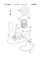
- FIG. 19illustrates generally a cross-sectional view of a highly preferred embodiment of the invention, in use with a particular type of T-MEI hearing aid.
- electromechanical input transducer 255is secured only to a vibrating auditory element, such as incus 45, which is mechanically isolated, as described above, from stapes 50 by a surgically shortened long arm portion 260. Sensing mechanical vibrations at incus 45 may offer more natural hearing due to the complex nature of the incudomalleolar joint coupling malleus 40 to incus 45.
- An electromechanical output transducer 265is secured only to a vibrated auditory element, such as stapes 50.
- Electromechanical input transducer 255comprises a piezoelectric film and inertial mass as described above with respect to the thirteenth embodiment of the invention.
- Electromechanical output transducer 265comprises a bi-element transducer and inertial mass as described above with respect to the sixth embodiment of the invention.
- Electromechanical vibrations of the incus 45are sensed by the electromechanical input transducer 255 and transduced into an electrical signal provided through lead wires 245 and 250 to electronics unit 95 implanted in the mastoid portion of temporal bone 80.
- Electronics unit 95further processes the electrical signal and provides an amplified electrical signal through lead wires 85 and 90 to electromechanical output transducer 265.
- Electromechanical output transducer 265transduces the amplified electrical signal into a mechanical vibration which is mechanically coupled to the stapes 50, and in turn coupled to the oval window 55 portion of cochlea 60.
- each of the above described embodimentsare intended to function as either electromechanical input transducers for sensing mechanical vibrations, or as electromechanical output transducers for producing mechanical vibrations.
- the above described embodimentsmay be switched between vibrating and vibrated auditory elements to obtain the desired functionality, and electrical signals can be accordingly coupled to an electronics unit of a P-MEI, T-MEI, or other hearing system.
- the inventioncould provide middle ear vibration sensing in conjunction with a cochlear implant, or other hearing system having output electrical stimuli.
- inventive concepts illustrated in particular embodimentsare intended to also apply to the other embodiments disclosed herein.
- the inventionprovides convenient piezoelectric input and output electromechanical transducers, each mounted only to the auditory element for which vibrations are transduced.
- the inventiondoes not require mounting a transducer to the temporal bone. This minimizes the invasive complexity of the surgical implantation procedure, and also minimizes steady state forces applied to the auditory element.
Landscapes
- Health & Medical Sciences (AREA)
- General Health & Medical Sciences (AREA)
- Otolaryngology (AREA)
- Neurosurgery (AREA)
- Physics & Mathematics (AREA)
- Engineering & Computer Science (AREA)
- Acoustics & Sound (AREA)
- Signal Processing (AREA)
- Piezo-Electric Transducers For Audible Bands (AREA)
Abstract
Description
Claims (7)
Priority Applications (3)
| Application Number | Priority Date | Filing Date | Title |
|---|---|---|---|
| US08/693,436US6005955A (en) | 1996-08-07 | 1996-08-07 | Middle ear transducer |
| PCT/US1997/013807WO1998006236A1 (en) | 1996-08-07 | 1997-08-07 | Middle ear transducer |
| DE19781940TDE19781940T1 (en) | 1996-08-07 | 1997-08-07 | Middle ear transducer |
Applications Claiming Priority (1)
| Application Number | Priority Date | Filing Date | Title |
|---|---|---|---|
| US08/693,436US6005955A (en) | 1996-08-07 | 1996-08-07 | Middle ear transducer |
Publications (1)
| Publication Number | Publication Date |
|---|---|
| US6005955Atrue US6005955A (en) | 1999-12-21 |
Family
ID=24784642
Family Applications (1)
| Application Number | Title | Priority Date | Filing Date |
|---|---|---|---|
| US08/693,436Expired - LifetimeUS6005955A (en) | 1996-08-07 | 1996-08-07 | Middle ear transducer |
Country Status (3)
| Country | Link |
|---|---|
| US (1) | US6005955A (en) |
| DE (1) | DE19781940T1 (en) |
| WO (1) | WO1998006236A1 (en) |
Cited By (68)
| Publication number | Priority date | Publication date | Assignee | Title |
|---|---|---|---|---|
| US6084975A (en)* | 1998-05-19 | 2000-07-04 | Resound Corporation | Promontory transmitting coil and tympanic membrane magnet for hearing devices |
| US6123660A (en)* | 1998-09-03 | 2000-09-26 | Implex Aktiengesellschaft Hearing Technology | Partially or fully implantable hearing aid |
| US6261223B1 (en)* | 1998-10-15 | 2001-07-17 | St. Croix Medical, Inc. | Method and apparatus for fixation type feedback reduction in implantable hearing assistance system |
| US20020012438A1 (en)* | 2000-06-30 | 2002-01-31 | Hans Leysieffer | System for rehabilitation of a hearing disorder |
| US6473651B1 (en) | 1999-03-02 | 2002-10-29 | Advanced Bionics Corporation | Fluid filled microphone balloon to be implanted in the middle ear |
| US6517476B1 (en) | 2000-05-30 | 2003-02-11 | Otologics Llc | Connector for implantable hearing aid |
| US6537201B1 (en) | 2001-09-28 | 2003-03-25 | Otologics Llc | Implantable hearing aid with improved sealing |
| US6565503B2 (en) | 2000-04-13 | 2003-05-20 | Cochlear Limited | At least partially implantable system for rehabilitation of hearing disorder |
| US6575894B2 (en) | 2000-04-13 | 2003-06-10 | Cochlear Limited | At least partially implantable system for rehabilitation of a hearing disorder |
| US20030163021A1 (en)* | 2002-02-26 | 2003-08-28 | Miller Douglas Alan | Method and system for external assessment of hearing aids that include implanted actuators |
| US20030161481A1 (en)* | 2002-02-26 | 2003-08-28 | Miller Douglas Alan | Method and system for external assessment of hearing aids that include implanted actuators |
| US20030161492A1 (en)* | 2002-02-26 | 2003-08-28 | Miller Douglas Alan | Frequency response equalization system for hearing aid microphones |
| US20030161482A1 (en)* | 2002-02-26 | 2003-08-28 | Miller Douglas Alan | Method and system for external assessment of hearing aids that include implanted actuators |
| US6664713B2 (en)* | 2001-12-04 | 2003-12-16 | Peter V. Boesen | Single chip device for voice communications |
| US6689045B2 (en) | 1998-09-24 | 2004-02-10 | St. Croix Medical, Inc. | Method and apparatus for improving signal quality in implantable hearing systems |
| US6712754B2 (en) | 2002-02-26 | 2004-03-30 | Otologics Llc | Method and system for positioning implanted hearing aid actuators |
| EP1435757A1 (en)* | 2002-12-30 | 2004-07-07 | Andrzej Zarowski | Device implantable in a bony wall of the inner ear |
| US20040264725A1 (en)* | 2003-05-19 | 2004-12-30 | Madsen Clair W. | Hearing aid system and transducer with hermetically sealed housing |
| US20050020873A1 (en)* | 2003-07-23 | 2005-01-27 | Epic Biosonics Inc. | Totally implantable hearing prosthesis |
| US20050131272A1 (en)* | 2003-12-11 | 2005-06-16 | Bernd Waldmann | Electrophysiological measurement method and system for positioning an implantable, hearing instrument transducer |
| US20050261700A1 (en)* | 2004-05-05 | 2005-11-24 | Gregor Tuma | Intramedullary pin tracking |
| US7110822B1 (en) | 2002-04-23 | 2006-09-19 | Advanced Bionics Corporation | Remote status and control device for a cochlear implant system |
| US20060247488A1 (en)* | 2005-04-27 | 2006-11-02 | Bernd Waldmann | Implantable hearing aid actuator positioning |
| US20070161848A1 (en)* | 2006-01-09 | 2007-07-12 | Cochlear Limited | Implantable interferometer microphone |
| US20070213788A1 (en)* | 2003-09-19 | 2007-09-13 | Osberger Mary J | Electrical stimulation of the inner ear in patients with unilateral hearing loss |
| US20090187233A1 (en)* | 2008-01-18 | 2009-07-23 | Stracener Steve W | Connector for implantable hearing aid |
| WO2009155650A1 (en) | 2008-06-25 | 2009-12-30 | Cochlear Limited | Enhanced performance implantable microphone system |
| US7668325B2 (en) | 2005-05-03 | 2010-02-23 | Earlens Corporation | Hearing system having an open chamber for housing components and reducing the occlusion effect |
| US7818066B1 (en) | 2002-04-23 | 2010-10-19 | Advanced Bionics, Llc | Remote status and control device for a cochlear implant system |
| WO2010141895A1 (en) | 2009-06-05 | 2010-12-09 | SoundBeam LLC | Optically coupled acoustic middle ear implant systems and methods |
| WO2010147935A1 (en) | 2009-06-15 | 2010-12-23 | SoundBeam LLC | Optically coupled active ossicular replacement prosthesis |
| US7867160B2 (en) | 2004-10-12 | 2011-01-11 | Earlens Corporation | Systems and methods for photo-mechanical hearing transduction |
| WO2011005500A2 (en) | 2009-06-22 | 2011-01-13 | SoundBeam LLC | Round window coupled hearing systems and methods |
| US20110015466A1 (en)* | 2008-02-07 | 2011-01-20 | Phonak Ag | Partially implantable hearing device |
| US20110112355A1 (en)* | 2008-06-13 | 2011-05-12 | Van Den Heuvel Koen | Implantable sound sensor for hearing prostheses |
| US8295523B2 (en) | 2007-10-04 | 2012-10-23 | SoundBeam LLC | Energy delivery and microphone placement methods for improved comfort in an open canal hearing aid |
| US8396239B2 (en) | 2008-06-17 | 2013-03-12 | Earlens Corporation | Optical electro-mechanical hearing devices with combined power and signal architectures |
| US8401212B2 (en) | 2007-10-12 | 2013-03-19 | Earlens Corporation | Multifunction system and method for integrated hearing and communication with noise cancellation and feedback management |
| US8401214B2 (en) | 2009-06-18 | 2013-03-19 | Earlens Corporation | Eardrum implantable devices for hearing systems and methods |
| US8715154B2 (en) | 2009-06-24 | 2014-05-06 | Earlens Corporation | Optically coupled cochlear actuator systems and methods |
| US8715153B2 (en) | 2009-06-22 | 2014-05-06 | Earlens Corporation | Optically coupled bone conduction systems and methods |
| US8715152B2 (en) | 2008-06-17 | 2014-05-06 | Earlens Corporation | Optical electro-mechanical hearing devices with separate power and signal components |
| US8824715B2 (en) | 2008-06-17 | 2014-09-02 | Earlens Corporation | Optical electro-mechanical hearing devices with combined power and signal architectures |
| US8845705B2 (en) | 2009-06-24 | 2014-09-30 | Earlens Corporation | Optical cochlear stimulation devices and methods |
| US8858419B2 (en) | 2008-09-22 | 2014-10-14 | Earlens Corporation | Balanced armature devices and methods for hearing |
| US20150156594A1 (en)* | 2013-11-29 | 2015-06-04 | Cochlear Limited | Medical device having an impulse force-resistant component |
| US20150208183A1 (en)* | 2014-01-21 | 2015-07-23 | Oticon Medical A/S | Hearing aid device using dual electromechanical vibrator |
| US9155887B2 (en) | 2010-10-19 | 2015-10-13 | Cochlear Limited | Relay interface for connecting an implanted medical device to an external electronics device |
| US9392377B2 (en) | 2010-12-20 | 2016-07-12 | Earlens Corporation | Anatomically customized ear canal hearing apparatus |
| US9924276B2 (en) | 2014-11-26 | 2018-03-20 | Earlens Corporation | Adjustable venting for hearing instruments |
| US9930458B2 (en) | 2014-07-14 | 2018-03-27 | Earlens Corporation | Sliding bias and peak limiting for optical hearing devices |
| US10034103B2 (en) | 2014-03-18 | 2018-07-24 | Earlens Corporation | High fidelity and reduced feedback contact hearing apparatus and methods |
| US10178483B2 (en) | 2015-12-30 | 2019-01-08 | Earlens Corporation | Light based hearing systems, apparatus, and methods |
| US10286215B2 (en) | 2009-06-18 | 2019-05-14 | Earlens Corporation | Optically coupled cochlear implant systems and methods |
| US10292601B2 (en) | 2015-10-02 | 2019-05-21 | Earlens Corporation | Wearable customized ear canal apparatus |
| US10341789B2 (en) | 2014-10-20 | 2019-07-02 | Cochlear Limited | Implantable auditory prosthesis with floating mass transducer |
| US10448136B2 (en) | 2011-12-07 | 2019-10-15 | Cochlear Limited | Electromechanical transducer with mechanical advantage |
| US10477332B2 (en) | 2016-07-18 | 2019-11-12 | Cochlear Limited | Integrity management of an implantable device |
| US10492010B2 (en) | 2015-12-30 | 2019-11-26 | Earlens Corporations | Damping in contact hearing systems |
| US10897677B2 (en) | 2017-03-24 | 2021-01-19 | Cochlear Limited | Shock and impact management of an implantable device during non use |
| US11102594B2 (en) | 2016-09-09 | 2021-08-24 | Earlens Corporation | Contact hearing systems, apparatus and methods |
| US11166114B2 (en) | 2016-11-15 | 2021-11-02 | Earlens Corporation | Impression procedure |
| US11212626B2 (en) | 2018-04-09 | 2021-12-28 | Earlens Corporation | Dynamic filter |
| US11223912B2 (en) | 2017-07-21 | 2022-01-11 | Cochlear Limited | Impact and resonance management |
| US11350226B2 (en) | 2015-12-30 | 2022-05-31 | Earlens Corporation | Charging protocol for rechargeable hearing systems |
| US11432084B2 (en) | 2016-10-28 | 2022-08-30 | Cochlear Limited | Passive integrity management of an implantable device |
| US11516603B2 (en) | 2018-03-07 | 2022-11-29 | Earlens Corporation | Contact hearing device and retention structure materials |
| US11924374B2 (en) | 2015-09-06 | 2024-03-05 | Cochlear Limited | System for real time, remote access to and adjustment of patient hearing aid with patient in normal life environment |
Families Citing this family (13)
| Publication number | Priority date | Publication date | Assignee | Title |
|---|---|---|---|---|
| AU1093600A (en) | 1998-10-14 | 2000-05-01 | Martin L Lenhardt | Stapedial-saccular strut |
| DE19923403C2 (en) | 1999-05-21 | 2002-11-14 | Phonak Ag Staefa | Device for mechanically coupling an electromechanical hearing aid transducer that can be implanted in a mastoid cavity |
| DE19931788C1 (en) | 1999-07-08 | 2000-11-30 | Implex Hear Tech Ag | Implanted mechanical coupling device for auditory ossicle chain in hearing aid system has associated settling device for movement of coupling device between open and closed positions |
| DE19935029C2 (en) | 1999-07-26 | 2003-02-13 | Phonak Ag Staefa | Implantable arrangement for mechanically coupling a driver part to a coupling point |
| DE19948375B4 (en) | 1999-10-07 | 2004-04-01 | Phonak Ag | Arrangement for mechanically coupling a driver to a coupling point of the ossicle chain |
| DE19948336C2 (en) | 1999-10-07 | 2002-02-28 | Implex Hear Tech Ag | Arrangement for coupling a driver to a coupling point of the ossicle chain |
| DE10039401C2 (en) | 2000-08-11 | 2002-06-13 | Implex Ag Hearing Technology I | At least partially implantable hearing system |
| DE10041726C1 (en) | 2000-08-25 | 2002-05-23 | Implex Ag Hearing Technology I | Implantable hearing system with means for measuring the coupling quality |
| DE10047388C1 (en) | 2000-09-25 | 2002-01-10 | Implex Hear Tech Ag | Implantable hearing system, includes a detachable coupling for securing and locating a transducer and a micro-manipulator |
| GB2449114A (en)* | 2007-05-11 | 2008-11-12 | Sentient Medical Ltd | Middle ear implant with piezoelectric actuator acting on stapes footplate |
| CN101827297B (en)* | 2010-05-26 | 2012-01-04 | 浙江师范大学 | Frequency-division piezoelectric bone conduction auditory device |
| US10321247B2 (en) | 2015-11-27 | 2019-06-11 | Cochlear Limited | External component with inductance and mechanical vibratory functionality |
| AT523707B1 (en)* | 2020-04-09 | 2021-11-15 | Fachhochschule Kaernten Gemeinnuetzige Privatstiftung | Device for the wireless transmission of energy and / or data |
Citations (30)
| Publication number | Priority date | Publication date | Assignee | Title |
|---|---|---|---|---|
| US3557775A (en)* | 1963-12-27 | 1971-01-26 | Jack Lawrence Mahoney | Method of implanting a hearing aid |
| US3594514A (en)* | 1970-01-02 | 1971-07-20 | Medtronic Inc | Hearing aid with piezoelectric ceramic element |
| US3712962A (en)* | 1971-04-05 | 1973-01-23 | J Epley | Implantable piezoelectric hearing aid |
| US3764748A (en)* | 1972-05-19 | 1973-10-09 | J Branch | Implanted hearing aids |
| US3931648A (en)* | 1975-01-08 | 1976-01-13 | Richards Manufacturing Company | Stapedial prosthesis |
| US3940974A (en)* | 1974-05-06 | 1976-03-02 | Minnesota Mining And Manufacturing Company | Electrically compensated sensor |
| FR2365267A1 (en)* | 1976-09-15 | 1978-04-14 | France Etat | Ear-piece for deaf people - has moulding with coil and magnetic disc fitted to hammer by grips through drum |
| US4315433A (en)* | 1980-03-19 | 1982-02-16 | The United States Of America As Represented By The Secretary Of The Army | Polymer film accelerometer |
| US4729366A (en)* | 1984-12-04 | 1988-03-08 | Medical Devices Group, Inc. | Implantable hearing aid and method of improving hearing |
| US4774933A (en)* | 1987-05-18 | 1988-10-04 | Xomed, Inc. | Method and apparatus for implanting hearing device |
| US4776322A (en)* | 1985-05-22 | 1988-10-11 | Xomed, Inc. | Implantable electromagnetic middle-ear bone-conduction hearing aid device |
| US4817607A (en)* | 1986-03-07 | 1989-04-04 | Richards Medical Company | Magnetic ossicular replacement prosthesis |
| US4840178A (en)* | 1986-03-07 | 1989-06-20 | Richards Metal Company | Magnet for installation in the middle ear |
| US4850962A (en)* | 1984-12-04 | 1989-07-25 | Medical Devices Group, Inc. | Implantable hearing aid and method of improving hearing |
| US4957478A (en)* | 1988-10-17 | 1990-09-18 | Maniglia Anthony J | Partially implantable hearing aid device |
| US5012520A (en)* | 1988-05-06 | 1991-04-30 | Siemens Aktiengesellschaft | Hearing aid with wireless remote control |
| US5015225A (en)* | 1985-05-22 | 1991-05-14 | Xomed, Inc. | Implantable electromagnetic middle-ear bone-conduction hearing aid device |
| US5015224A (en)* | 1988-10-17 | 1991-05-14 | Maniglia Anthony J | Partially implantable hearing aid device |
| WO1992008330A1 (en)* | 1990-11-01 | 1992-05-14 | Cochlear Pty. Limited | Bimodal speech processor |
| US5163957A (en)* | 1991-09-10 | 1992-11-17 | Smith & Nephew Richards, Inc. | Ossicular prosthesis for mounting magnet |
| US5277694A (en)* | 1991-02-13 | 1994-01-11 | Implex Gmbh | Electromechanical transducer for implantable hearing aids |
| US5282858A (en)* | 1991-06-17 | 1994-02-01 | American Cyanamid Company | Hermetically sealed implantable transducer |
| WO1994017645A1 (en)* | 1993-01-25 | 1994-08-04 | Auditory Micromachines, Inc. | Implantable auditory system with micromachined microsensor and microactuator |
| US5338287A (en)* | 1991-12-23 | 1994-08-16 | Miller Gale W | Electromagnetic induction hearing aid device |
| US5360388A (en)* | 1992-10-09 | 1994-11-01 | The University Of Virginia Patents Foundation | Round window electromagnetic implantable hearing aid |
| US5411467A (en)* | 1989-06-02 | 1995-05-02 | Implex Gmbh Spezialhorgerate | Implantable hearing aid |
| US5456654A (en)* | 1993-07-01 | 1995-10-10 | Ball; Geoffrey R. | Implantable magnetic hearing aid transducer |
| US5498226A (en)* | 1990-03-05 | 1996-03-12 | Lenkauskas; Edmundas | Totally implanted hearing device |
| US5554096A (en)* | 1993-07-01 | 1996-09-10 | Symphonix | Implantable electromagnetic hearing transducer |
| US5624376A (en)* | 1993-07-01 | 1997-04-29 | Symphonix Devices, Inc. | Implantable and external hearing systems having a floating mass transducer |
- 1996
- 1996-08-07USUS08/693,436patent/US6005955A/ennot_activeExpired - Lifetime
- 1997
- 1997-08-07DEDE19781940Tpatent/DE19781940T1/ennot_activeWithdrawn
- 1997-08-07WOPCT/US1997/013807patent/WO1998006236A1/enactiveApplication Filing
Patent Citations (31)
| Publication number | Priority date | Publication date | Assignee | Title |
|---|---|---|---|---|
| US3557775A (en)* | 1963-12-27 | 1971-01-26 | Jack Lawrence Mahoney | Method of implanting a hearing aid |
| US3594514A (en)* | 1970-01-02 | 1971-07-20 | Medtronic Inc | Hearing aid with piezoelectric ceramic element |
| US3712962A (en)* | 1971-04-05 | 1973-01-23 | J Epley | Implantable piezoelectric hearing aid |
| US3764748A (en)* | 1972-05-19 | 1973-10-09 | J Branch | Implanted hearing aids |
| US3940974A (en)* | 1974-05-06 | 1976-03-02 | Minnesota Mining And Manufacturing Company | Electrically compensated sensor |
| US3931648A (en)* | 1975-01-08 | 1976-01-13 | Richards Manufacturing Company | Stapedial prosthesis |
| FR2365267A1 (en)* | 1976-09-15 | 1978-04-14 | France Etat | Ear-piece for deaf people - has moulding with coil and magnetic disc fitted to hammer by grips through drum |
| US4315433A (en)* | 1980-03-19 | 1982-02-16 | The United States Of America As Represented By The Secretary Of The Army | Polymer film accelerometer |
| US4729366A (en)* | 1984-12-04 | 1988-03-08 | Medical Devices Group, Inc. | Implantable hearing aid and method of improving hearing |
| US4850962A (en)* | 1984-12-04 | 1989-07-25 | Medical Devices Group, Inc. | Implantable hearing aid and method of improving hearing |
| US4776322A (en)* | 1985-05-22 | 1988-10-11 | Xomed, Inc. | Implantable electromagnetic middle-ear bone-conduction hearing aid device |
| US5015225A (en)* | 1985-05-22 | 1991-05-14 | Xomed, Inc. | Implantable electromagnetic middle-ear bone-conduction hearing aid device |
| US4817607A (en)* | 1986-03-07 | 1989-04-04 | Richards Medical Company | Magnetic ossicular replacement prosthesis |
| US4840178A (en)* | 1986-03-07 | 1989-06-20 | Richards Metal Company | Magnet for installation in the middle ear |
| US4774933A (en)* | 1987-05-18 | 1988-10-04 | Xomed, Inc. | Method and apparatus for implanting hearing device |
| US5012520A (en)* | 1988-05-06 | 1991-04-30 | Siemens Aktiengesellschaft | Hearing aid with wireless remote control |
| US4957478A (en)* | 1988-10-17 | 1990-09-18 | Maniglia Anthony J | Partially implantable hearing aid device |
| US5015224A (en)* | 1988-10-17 | 1991-05-14 | Maniglia Anthony J | Partially implantable hearing aid device |
| US5411467A (en)* | 1989-06-02 | 1995-05-02 | Implex Gmbh Spezialhorgerate | Implantable hearing aid |
| US5498226A (en)* | 1990-03-05 | 1996-03-12 | Lenkauskas; Edmundas | Totally implanted hearing device |
| WO1992008330A1 (en)* | 1990-11-01 | 1992-05-14 | Cochlear Pty. Limited | Bimodal speech processor |
| US5277694A (en)* | 1991-02-13 | 1994-01-11 | Implex Gmbh | Electromechanical transducer for implantable hearing aids |
| US5282858A (en)* | 1991-06-17 | 1994-02-01 | American Cyanamid Company | Hermetically sealed implantable transducer |
| US5163957A (en)* | 1991-09-10 | 1992-11-17 | Smith & Nephew Richards, Inc. | Ossicular prosthesis for mounting magnet |
| US5338287A (en)* | 1991-12-23 | 1994-08-16 | Miller Gale W | Electromagnetic induction hearing aid device |
| US5360388A (en)* | 1992-10-09 | 1994-11-01 | The University Of Virginia Patents Foundation | Round window electromagnetic implantable hearing aid |
| WO1994017645A1 (en)* | 1993-01-25 | 1994-08-04 | Auditory Micromachines, Inc. | Implantable auditory system with micromachined microsensor and microactuator |
| US5531787A (en)* | 1993-01-25 | 1996-07-02 | Lesinski; S. George | Implantable auditory system with micromachined microsensor and microactuator |
| US5456654A (en)* | 1993-07-01 | 1995-10-10 | Ball; Geoffrey R. | Implantable magnetic hearing aid transducer |
| US5554096A (en)* | 1993-07-01 | 1996-09-10 | Symphonix | Implantable electromagnetic hearing transducer |
| US5624376A (en)* | 1993-07-01 | 1997-04-29 | Symphonix Devices, Inc. | Implantable and external hearing systems having a floating mass transducer |
Non-Patent Citations (58)
| Title |
|---|
| . rederickson, et al., "Ongoing Investigations into an Implantable Electromagnetic Hearing Aid for Moderate to Sever into Sensorineural Hearing Loss", Otolaryngological Clinics of North America, vol. 28, No. 1, 107-121, Feb. 1995. |
| . . rederickson, et al., Ongoing Investigations into an Implantable Electromagnetic Hearing Aid for Moderate to Sever into Sensorineural Hearing Loss , Otolaryngological Clinics of North America, vol. 28, No. 1, 107 121, Feb. 1995.* |
| A. J. Maniglia, et al., "A Contactless Electromagnetic Implantable Middle Ear Sevice for Sensorineural Hearing Loss", ENT Journal, vol. 73, No. 2, 78-90, Feb. 1994. |
| A. J. Maniglia, et al., "Contactless, Semi-Implantable Electromagnetic Hearing Device for the treatment of Sensorineural Hearing Loss", Abstract of Paper Presented at International Symposium on Electronic Implants in Otology and Conventional Hearing Aids, Nov. 11-14, 1993. |
| A. J. Maniglia, et al., A Contactless Electromagnetic Implantable Middle Ear Sevice for Sensorineural Hearing Loss , ENT Journal, vol. 73, No. 2, 78 90, Feb. 1994.* |
| A. J. Maniglia, et al., Contactless, Semi Implantable Electromagnetic Hearing Device for the treatment of Sensorineural Hearing Loss , Abstract of Paper Presented at International Symposium on Electronic Implants in Otology and Conventional Hearing Aids, Nov. 11 14, 1993.* |
| D.B. Welling, et al., "Auditory Stimulation og the Inner Ear via Semicircular Canals", Abstract of paper presented at International Symposium on Electronic Implants in otology and Conventional Hearing Aids, Walt Disney World Swan Abstract #9, Nov. 11-14, 1993. |
| D.B. Welling, et al., Auditory Stimulation og the Inner Ear via Semicircular Canals , Abstract of paper presented at International Symposium on Electronic Implants in otology and Conventional Hearing Aids, Walt Disney World Swan Abstract 9, Nov. 11 14, 1993.* |
| G. Jako, "Biomedical Engineering in Ear Surgery", Otolaryngological Clinics of North America, vol. 5, No. 1, 173-182, Feb. 1972. |
| G. Jako, Biomedical Engineering in Ear Surgery , Otolaryngological Clinics of North America, vol. 5, No. 1, 173 182, Feb. 1972.* |
| Goode, M.D., R.L., "Electromagnetic Implantable Hearing Aids," Advances in Audiology (Karger, Basel), 4:22-31, (1988). |
| Goode, M.D., R.L., Electromagnetic Implantable Hearing Aids, Advances in Audiology (Karger, Basel), 4:22 31, (1988).* |
| Gyo, K., et al., "Measurement of Stapes Vibration Driven by the Ceramic Vibrator of a Middle Ear Implant-Human Temporal Bone Experiments," Advances in Audiology (Karger, Basel), 4:107-116, (1988). |
| Gyo, K., et al., Measurement of Stapes Vibration Driven by the Ceramic Vibrator of a Middle Ear Implant Human Temporal Bone Experiments, Advances in Audiology (Karger, Basel), 4:107 116, (1988).* |
| Heide, J., et al., "Development of a Semi-Implantable Hearing Device," Advances in Audiology (Karger, Basel), 4:32-43, (1988). |
| Heide, J., et al., Development of a Semi Implantable Hearing Device, Advances in Audiology (Karger, Basel), 4:32 43, (1988).* |
| Hiki, S., et al., "Audiological Evaluation of the Middle Ear Implant," Advances in Audiology (Karger, Basel), 4:134-148, (1988). |
| Hiki, S., et al., Audiological Evaluation of the Middle Ear Implant, Advances in Audiology (Karger, Basel), 4:134 148, (1988).* |
| iddle Ear Implant: Implantable Aids, Advance in Audiology, ol. 4, M. Hoke Editor, arger, 1 169, 1988.* |
| iddle Ear Implant: Implantable Aids, Advance in Audiology, ol. 4, M. Hoke Editor, arger, 1-169, 1988. |
| Ikeda, H., et al., "Energy Source for the Middle Ear Implant," Advances in Audiology (Karger, Basel), 4:73-84, (1988). |
| Ikeda, H., et al., Energy Source for the Middle Ear Implant, Advances in Audiology (Karger, Basel), 4:73 84, (1988).* |
| Jun Ichi Suzuki, et al., Long Term Clinical Resilts of the Partially Implantable Piezoelectric Middle Ear Implant , ENT Journal, vol. 73, No. 2, 104 107, Feb. 1994.* |
| Jun-Ichi Suzuki, et al., "Long-Term Clinical Resilts of the Partially Implantable Piezoelectric Middle Ear Implant", ENT Journal, vol. 73, No. 2, 104-107, Feb. 1994. |
| K. Gyo, et al., "Stapes Vibration Produced by the Output Transducer of an Implantable Hearing Aid", Arch Otolaryngol Head Neck Surg., vol. 113, 1078-1081, Oct. 1987. |
| K. Gyo, et al., Stapes Vibration Produced by the Output Transducer of an Implantable Hearing Aid , Arch Otolaryngol Head Neck Surg., vol. 113, 1078 1081, Oct. 1987.* |
| K. Kodera, et al., "Sound Evaluation of Partially Implantable Piezoelectric Middle Ear Implant: Comparative Study of frequency Responses", ENT Journal, vol. 73, No. 2, 108-111, Feb. 1994. |
| K. Kodera, et al., Sound Evaluation of Partially Implantable Piezoelectric Middle Ear Implant: Comparative Study of frequency Responses , ENT Journal, vol. 73, No. 2, 108 111, Feb. 1994.* |
| K.. Gyo, et al., "Sound Pickup Utilizing an Implantable Piezpelectric Ceramic Bimorph Element: Application to the Cochlear Implant", American Journal of Otology, vol. 5, No. 4, 273-276, Apr. 1987. |
| K.. Gyo, et al., Sound Pickup Utilizing an Implantable Piezpelectric Ceramic Bimorph Element: Application to the Cochlear Implant , American Journal of Otology, vol. 5, No. 4, 273 276, Apr. 1987.* |
| Kodera, K., et al., "Evaluation of the Ceramic Vibrator in the Cat," Advances in Audiology (Karger, Basel), 4:97-106, (1988). |
| Kodera, K., et al., Evaluation of the Ceramic Vibrator in the Cat, Advances in Audiology (Karger, Basel), 4:97 106, (1988).* |
| Kodera, M.D., K., et al., "Evaluation of the Implantable Microphone in the Cat," Advances in Audiology (Karger, Basel), 4:117-123, (1988). |
| Kodera, M.D., K., et al., Evaluation of the Implantable Microphone in the Cat, Advances in Audiology (Karger, Basel), 4:117 123, (1988).* |
| M. Tos, et al., "Implantation of Electromagnetic Ossicular Replacement Device", ENT Journal, vol. 73, No. 2, 93-103, Feb. 1993. |
| M. Tos, et al., Implantation of Electromagnetic Ossicular Replacement Device , ENT Journal, vol. 73, No. 2, 93 103, Feb. 1993.* |
| N. Yanagihara, et al., "Partially Implantable Hearing Aid using Piezoelectric Ceramic Ossicular Vibrator", Abstract of Paper Presented at International Symposium on Electronic Implants in Otology and Conventional Hearing Aids, Walt Disnry World Swan #26, Nov. 11-14, 1993. |
| N. Yanagihara, et al., Partially Implantable Hearing Aid using Piezoelectric Ceramic Ossicular Vibrator , Abstract of Paper Presented at International Symposium on Electronic Implants in Otology and Conventional Hearing Aids, Walt Disnry World Swan 26, Nov. 11 14, 1993.* |
| Ohno, T., et al., "Performance of the Middle Ear Implants," Advances in Audiology (Karger, Basel), 4:85-96, (1988). |
| Ohno, T., et al., "Structure and Performance of the Main Components," Advances in Audiology (Karger, Basel), 4:52-72, (1988). |
| Ohno, T., et al., Performance of the Middle Ear Implants, Advances in Audiology (Karger, Basel), 4:85 96, (1988).* |
| Ohno, T., et al., Structure and Performance of the Main Components, Advances in Audiology (Karger, Basel), 4:52 72, (1988).* |
| Suzuki, J.I., et al., "Early Studies and the History of Development of the Middle Ear Implant in Japan," Advances in Audiology (Karger, Basel), 4:1-14, (1988). |
| Suzuki, J.I., et al., "Implantation of Partially Implantable Middle Ear Implant and the Indication," Advances in Audiology (Karger, Basel), 4:160-166 (1988). |
| Suzuki, J.I., et al., "Principle, Construction and Indication of the Middle Ear Implant," Advances in Audiology, 4:15-21, (1988). |
| Suzuki, J.I., et al., Early Studies and the History of Development of the Middle Ear Implant in Japan, Advances in Audiology (Karger, Basel), 4:1 14, (1988).* |
| Suzuki, J.I., et al., Implantation of Partially Implantable Middle Ear Implant and the Indication, Advances in Audiology (Karger, Basel), 4:160 166 (1988).* |
| Suzuki, J.I., et al., Principle, Construction and Indication of the Middle Ear Implant, Advances in Audiology, 4:15 21, (1988).* |
| T. Dumon, et al., "Piezoelectric Middle Ear Implant: Experimental Results", Abstract of Paper Presented at International Symposium on Electronic Implants in Otology and Conventional Hearing Aids, Walt Disney World Swan, Abstract #35, Nov. 11-14, 1996. |
| T. Dumon, et al., Piezoelectric Middle Ear Implant: Experimental Results , Abstract of Paper Presented at International Symposium on Electronic Implants in Otology and Conventional Hearing Aids, Walt Disney World Swan, Abstract 35, Nov. 11 14, 1996.* |
| Tjellstr o m, A., Vibratory Stimulation of the Cochlea through a Percutaneous Transducer, Advances in Audiology (Karger Basel), 4:44 50, (1988).* |
| Tjellstrom, A., "Vibratory Stimulation of the Cochlea through a Percutaneous Transducer," Advances in Audiology (Karger Basel), 4:44-50, (1988). |
| Wen H. Ko, et al., "Engineering Principles of Mechanical Stimulation of the Middle Ear", Otolaryngological Clinics of North America, vol. 28, No. 1, 29-41, Feb. 1995. |
| Wen H. Ko, et al., Engineering Principles of Mechanical Stimulation of the Middle Ear , Otolaryngological Clinics of North America, vol. 28, No. 1, 29 41, Feb. 1995.* |
| Yanagihara, N., et al., "Efficacy of the Partially Implantable Middle Ear Implant in Middle and Inner Ear Disorders," Advances in Audiology, 4:149-159, (1988). |
| Yanagihara, N., et al., "Intraoperative Assessment of Vibrator-Induced Hearing," Advances in Audiology, 4:124-133, (1988). |
| Yanagihara, N., et al., Efficacy of the Partially Implantable Middle Ear Implant in Middle and Inner Ear Disorders, Advances in Audiology, 4:149 159, (1988).* |
| Yanagihara, N., et al., Intraoperative Assessment of Vibrator Induced Hearing, Advances in Audiology, 4:124 133, (1988).* |
Cited By (139)
| Publication number | Priority date | Publication date | Assignee | Title |
|---|---|---|---|---|
| US6084975A (en)* | 1998-05-19 | 2000-07-04 | Resound Corporation | Promontory transmitting coil and tympanic membrane magnet for hearing devices |
| US6123660A (en)* | 1998-09-03 | 2000-09-26 | Implex Aktiengesellschaft Hearing Technology | Partially or fully implantable hearing aid |
| US6689045B2 (en) | 1998-09-24 | 2004-02-10 | St. Croix Medical, Inc. | Method and apparatus for improving signal quality in implantable hearing systems |
| US6261223B1 (en)* | 1998-10-15 | 2001-07-17 | St. Croix Medical, Inc. | Method and apparatus for fixation type feedback reduction in implantable hearing assistance system |
| US6585637B2 (en)* | 1998-10-15 | 2003-07-01 | St. Croix Medical, Inc. | Method and apparatus for fixation type feedback reduction in implantable hearing assistance systems |
| US6473651B1 (en) | 1999-03-02 | 2002-10-29 | Advanced Bionics Corporation | Fluid filled microphone balloon to be implanted in the middle ear |
| US6565503B2 (en) | 2000-04-13 | 2003-05-20 | Cochlear Limited | At least partially implantable system for rehabilitation of hearing disorder |
| US6575894B2 (en) | 2000-04-13 | 2003-06-10 | Cochlear Limited | At least partially implantable system for rehabilitation of a hearing disorder |
| US6517476B1 (en) | 2000-05-30 | 2003-02-11 | Otologics Llc | Connector for implantable hearing aid |
| US20020012438A1 (en)* | 2000-06-30 | 2002-01-31 | Hans Leysieffer | System for rehabilitation of a hearing disorder |
| US7376563B2 (en) | 2000-06-30 | 2008-05-20 | Cochlear Limited | System for rehabilitation of a hearing disorder |
| US6537201B1 (en) | 2001-09-28 | 2003-03-25 | Otologics Llc | Implantable hearing aid with improved sealing |
| US6664713B2 (en)* | 2001-12-04 | 2003-12-16 | Peter V. Boesen | Single chip device for voice communications |
| US20030161482A1 (en)* | 2002-02-26 | 2003-08-28 | Miller Douglas Alan | Method and system for external assessment of hearing aids that include implanted actuators |
| US7197152B2 (en) | 2002-02-26 | 2007-03-27 | Otologics Llc | Frequency response equalization system for hearing aid microphones |
| US20030161492A1 (en)* | 2002-02-26 | 2003-08-28 | Miller Douglas Alan | Frequency response equalization system for hearing aid microphones |
| US6712754B2 (en) | 2002-02-26 | 2004-03-30 | Otologics Llc | Method and system for positioning implanted hearing aid actuators |
| US20060269076A1 (en)* | 2002-02-26 | 2006-11-30 | Miller Douglas A | Method and system for external assessment of hearing aids that include implanted actuators |
| US20030163021A1 (en)* | 2002-02-26 | 2003-08-28 | Miller Douglas Alan | Method and system for external assessment of hearing aids that include implanted actuators |
| US20030161481A1 (en)* | 2002-02-26 | 2003-08-28 | Miller Douglas Alan | Method and system for external assessment of hearing aids that include implanted actuators |
| US7447319B2 (en) | 2002-02-26 | 2008-11-04 | Otologics, Llc | Method and system for external assessment of hearing aids that include implanted actuators |
| US6879693B2 (en) | 2002-02-26 | 2005-04-12 | Otologics, Llc. | Method and system for external assessment of hearing aids that include implanted actuators |
| US7110822B1 (en) | 2002-04-23 | 2006-09-19 | Advanced Bionics Corporation | Remote status and control device for a cochlear implant system |
| US7818066B1 (en) | 2002-04-23 | 2010-10-19 | Advanced Bionics, Llc | Remote status and control device for a cochlear implant system |
| US7618450B2 (en) | 2002-12-30 | 2009-11-17 | 3Win N.V. | Implantable hearing system |
| US20060161255A1 (en)* | 2002-12-30 | 2006-07-20 | Andrej Zarowski | Implantable hearing system |
| CN1732712B (en)* | 2002-12-30 | 2010-06-23 | 3Win股份有限公司 | Combined equipment comprising implantable apparatus and vibration actuator, and the implantable apparatus |
| WO2004060015A1 (en)* | 2002-12-30 | 2004-07-15 | 3Win N.V. | Implantable hearing system |
| EP1435757A1 (en)* | 2002-12-30 | 2004-07-07 | Andrzej Zarowski | Device implantable in a bony wall of the inner ear |
| US7524278B2 (en) | 2003-05-19 | 2009-04-28 | Envoy Medical Corporation | Hearing aid system and transducer with hermetically sealed housing |
| US20040264725A1 (en)* | 2003-05-19 | 2004-12-30 | Madsen Clair W. | Hearing aid system and transducer with hermetically sealed housing |
| US7442164B2 (en)* | 2003-07-23 | 2008-10-28 | Med-El Elektro-Medizinische Gerate Gesellschaft M.B.H. | Totally implantable hearing prosthesis |
| US20050020873A1 (en)* | 2003-07-23 | 2005-01-27 | Epic Biosonics Inc. | Totally implantable hearing prosthesis |
| US20070213788A1 (en)* | 2003-09-19 | 2007-09-13 | Osberger Mary J | Electrical stimulation of the inner ear in patients with unilateral hearing loss |
| US20050131272A1 (en)* | 2003-12-11 | 2005-06-16 | Bernd Waldmann | Electrophysiological measurement method and system for positioning an implantable, hearing instrument transducer |
| US7137946B2 (en) | 2003-12-11 | 2006-11-21 | Otologics Llc | Electrophysiological measurement method and system for positioning an implantable, hearing instrument transducer |
| US20050261700A1 (en)* | 2004-05-05 | 2005-11-24 | Gregor Tuma | Intramedullary pin tracking |
| US8382759B2 (en)* | 2004-05-05 | 2013-02-26 | Brainlab Ag | Intramedullary pin tracking |
| US9226083B2 (en) | 2004-07-28 | 2015-12-29 | Earlens Corporation | Multifunction system and method for integrated hearing and communication with noise cancellation and feedback management |
| US7867160B2 (en) | 2004-10-12 | 2011-01-11 | Earlens Corporation | Systems and methods for photo-mechanical hearing transduction |
| US8696541B2 (en) | 2004-10-12 | 2014-04-15 | Earlens Corporation | Systems and methods for photo-mechanical hearing transduction |
| US7582052B2 (en) | 2005-04-27 | 2009-09-01 | Otologics, Llc | Implantable hearing aid actuator positioning |
| US20060247488A1 (en)* | 2005-04-27 | 2006-11-02 | Bernd Waldmann | Implantable hearing aid actuator positioning |
| US7668325B2 (en) | 2005-05-03 | 2010-02-23 | Earlens Corporation | Hearing system having an open chamber for housing components and reducing the occlusion effect |
| US9154891B2 (en) | 2005-05-03 | 2015-10-06 | Earlens Corporation | Hearing system having improved high frequency response |
| US9949039B2 (en) | 2005-05-03 | 2018-04-17 | Earlens Corporation | Hearing system having improved high frequency response |
| US20070161848A1 (en)* | 2006-01-09 | 2007-07-12 | Cochlear Limited | Implantable interferometer microphone |
| US8014871B2 (en) | 2006-01-09 | 2011-09-06 | Cochlear Limited | Implantable interferometer microphone |
| US8295523B2 (en) | 2007-10-04 | 2012-10-23 | SoundBeam LLC | Energy delivery and microphone placement methods for improved comfort in an open canal hearing aid |
| US10863286B2 (en) | 2007-10-12 | 2020-12-08 | Earlens Corporation | Multifunction system and method for integrated hearing and communication with noise cancellation and feedback management |
| US10516950B2 (en) | 2007-10-12 | 2019-12-24 | Earlens Corporation | Multifunction system and method for integrated hearing and communication with noise cancellation and feedback management |
| US10154352B2 (en) | 2007-10-12 | 2018-12-11 | Earlens Corporation | Multifunction system and method for integrated hearing and communication with noise cancellation and feedback management |
| US11483665B2 (en) | 2007-10-12 | 2022-10-25 | Earlens Corporation | Multifunction system and method for integrated hearing and communication with noise cancellation and feedback management |
| US8401212B2 (en) | 2007-10-12 | 2013-03-19 | Earlens Corporation | Multifunction system and method for integrated hearing and communication with noise cancellation and feedback management |
| US7822479B2 (en) | 2008-01-18 | 2010-10-26 | Otologics, Llc | Connector for implantable hearing aid |
| US20090187233A1 (en)* | 2008-01-18 | 2009-07-23 | Stracener Steve W | Connector for implantable hearing aid |
| US20110015466A1 (en)* | 2008-02-07 | 2011-01-20 | Phonak Ag | Partially implantable hearing device |
| US9179226B2 (en)* | 2008-02-07 | 2015-11-03 | Advanced Bionics Ag | Partially implantable hearing device |
| US20110112355A1 (en)* | 2008-06-13 | 2011-05-12 | Van Den Heuvel Koen | Implantable sound sensor for hearing prostheses |
| US9533143B2 (en)* | 2008-06-13 | 2017-01-03 | Cochlear Limited | Implantable sound sensor for hearing prostheses |
| US8396239B2 (en) | 2008-06-17 | 2013-03-12 | Earlens Corporation | Optical electro-mechanical hearing devices with combined power and signal architectures |
| US10516949B2 (en) | 2008-06-17 | 2019-12-24 | Earlens Corporation | Optical electro-mechanical hearing devices with separate power and signal components |
| US8715152B2 (en) | 2008-06-17 | 2014-05-06 | Earlens Corporation | Optical electro-mechanical hearing devices with separate power and signal components |
| US9961454B2 (en) | 2008-06-17 | 2018-05-01 | Earlens Corporation | Optical electro-mechanical hearing devices with separate power and signal components |
| US8824715B2 (en) | 2008-06-17 | 2014-09-02 | Earlens Corporation | Optical electro-mechanical hearing devices with combined power and signal architectures |
| US11310605B2 (en) | 2008-06-17 | 2022-04-19 | Earlens Corporation | Optical electro-mechanical hearing devices with separate power and signal components |
| US9591409B2 (en) | 2008-06-17 | 2017-03-07 | Earlens Corporation | Optical electro-mechanical hearing devices with separate power and signal components |
| US9049528B2 (en) | 2008-06-17 | 2015-06-02 | Earlens Corporation | Optical electro-mechanical hearing devices with combined power and signal architectures |
| WO2009155650A1 (en) | 2008-06-25 | 2009-12-30 | Cochlear Limited | Enhanced performance implantable microphone system |
| US10516946B2 (en) | 2008-09-22 | 2019-12-24 | Earlens Corporation | Devices and methods for hearing |
| US10743110B2 (en) | 2008-09-22 | 2020-08-11 | Earlens Corporation | Devices and methods for hearing |
| EP3509324A1 (en) | 2008-09-22 | 2019-07-10 | Earlens Corporation | Balanced armature devices and methods for hearing |
| US11057714B2 (en) | 2008-09-22 | 2021-07-06 | Earlens Corporation | Devices and methods for hearing |
| US10237663B2 (en) | 2008-09-22 | 2019-03-19 | Earlens Corporation | Devices and methods for hearing |
| US10511913B2 (en) | 2008-09-22 | 2019-12-17 | Earlens Corporation | Devices and methods for hearing |
| US8858419B2 (en) | 2008-09-22 | 2014-10-14 | Earlens Corporation | Balanced armature devices and methods for hearing |
| US9749758B2 (en) | 2008-09-22 | 2017-08-29 | Earlens Corporation | Devices and methods for hearing |
| US9949035B2 (en) | 2008-09-22 | 2018-04-17 | Earlens Corporation | Transducer devices and methods for hearing |
| WO2010141895A1 (en) | 2009-06-05 | 2010-12-09 | SoundBeam LLC | Optically coupled acoustic middle ear implant systems and methods |
| US9055379B2 (en) | 2009-06-05 | 2015-06-09 | Earlens Corporation | Optically coupled acoustic middle ear implant systems and methods |
| WO2010147935A1 (en) | 2009-06-15 | 2010-12-23 | SoundBeam LLC | Optically coupled active ossicular replacement prosthesis |
| US9544700B2 (en) | 2009-06-15 | 2017-01-10 | Earlens Corporation | Optically coupled active ossicular replacement prosthesis |
| US8401214B2 (en) | 2009-06-18 | 2013-03-19 | Earlens Corporation | Eardrum implantable devices for hearing systems and methods |
| US8787609B2 (en) | 2009-06-18 | 2014-07-22 | Earlens Corporation | Eardrum implantable devices for hearing systems and methods |
| US9277335B2 (en) | 2009-06-18 | 2016-03-01 | Earlens Corporation | Eardrum implantable devices for hearing systems and methods |
| US10286215B2 (en) | 2009-06-18 | 2019-05-14 | Earlens Corporation | Optically coupled cochlear implant systems and methods |
| US8715153B2 (en) | 2009-06-22 | 2014-05-06 | Earlens Corporation | Optically coupled bone conduction systems and methods |
| WO2011005500A2 (en) | 2009-06-22 | 2011-01-13 | SoundBeam LLC | Round window coupled hearing systems and methods |
| US20110152602A1 (en)* | 2009-06-22 | 2011-06-23 | SoundBeam LLC | Round Window Coupled Hearing Systems and Methods |
| US11323829B2 (en) | 2009-06-22 | 2022-05-03 | Earlens Corporation | Round window coupled hearing systems and methods |
| US10555100B2 (en) | 2009-06-22 | 2020-02-04 | Earlens Corporation | Round window coupled hearing systems and methods |
| US8715154B2 (en) | 2009-06-24 | 2014-05-06 | Earlens Corporation | Optically coupled cochlear actuator systems and methods |
| US8845705B2 (en) | 2009-06-24 | 2014-09-30 | Earlens Corporation | Optical cochlear stimulation devices and methods |
| US8986187B2 (en) | 2009-06-24 | 2015-03-24 | Earlens Corporation | Optically coupled cochlear actuator systems and methods |
| US11376442B2 (en)* | 2010-10-19 | 2022-07-05 | Cochlear Limited | Relay interface for connecting an implanted medical device to an external electronics device |
| US10485974B2 (en) | 2010-10-19 | 2019-11-26 | Cochlear Limited | Relay interface for connecting an implanted medical device to an external electronics device |
| US9155887B2 (en) | 2010-10-19 | 2015-10-13 | Cochlear Limited | Relay interface for connecting an implanted medical device to an external electronics device |
| US11743663B2 (en) | 2010-12-20 | 2023-08-29 | Earlens Corporation | Anatomically customized ear canal hearing apparatus |
| US11153697B2 (en) | 2010-12-20 | 2021-10-19 | Earlens Corporation | Anatomically customized ear canal hearing apparatus |
| US10284964B2 (en) | 2010-12-20 | 2019-05-07 | Earlens Corporation | Anatomically customized ear canal hearing apparatus |
| EP3758394A1 (en) | 2010-12-20 | 2020-12-30 | Earlens Corporation | Anatomically customized ear canal hearing apparatus |
| US9392377B2 (en) | 2010-12-20 | 2016-07-12 | Earlens Corporation | Anatomically customized ear canal hearing apparatus |
| US10609492B2 (en) | 2010-12-20 | 2020-03-31 | Earlens Corporation | Anatomically customized ear canal hearing apparatus |
| US10448136B2 (en) | 2011-12-07 | 2019-10-15 | Cochlear Limited | Electromechanical transducer with mechanical advantage |
| US20150156594A1 (en)* | 2013-11-29 | 2015-06-04 | Cochlear Limited | Medical device having an impulse force-resistant component |
| US9510115B2 (en)* | 2014-01-21 | 2016-11-29 | Oticon Medical A/S | Hearing aid device using dual electromechanical vibrator |
| US20150208183A1 (en)* | 2014-01-21 | 2015-07-23 | Oticon Medical A/S | Hearing aid device using dual electromechanical vibrator |
| US10034103B2 (en) | 2014-03-18 | 2018-07-24 | Earlens Corporation | High fidelity and reduced feedback contact hearing apparatus and methods |
| US11317224B2 (en) | 2014-03-18 | 2022-04-26 | Earlens Corporation | High fidelity and reduced feedback contact hearing apparatus and methods |
| US10531206B2 (en) | 2014-07-14 | 2020-01-07 | Earlens Corporation | Sliding bias and peak limiting for optical hearing devices |
| US11800303B2 (en) | 2014-07-14 | 2023-10-24 | Earlens Corporation | Sliding bias and peak limiting for optical hearing devices |
| US11259129B2 (en) | 2014-07-14 | 2022-02-22 | Earlens Corporation | Sliding bias and peak limiting for optical hearing devices |
| US9930458B2 (en) | 2014-07-14 | 2018-03-27 | Earlens Corporation | Sliding bias and peak limiting for optical hearing devices |
| US10341789B2 (en) | 2014-10-20 | 2019-07-02 | Cochlear Limited | Implantable auditory prosthesis with floating mass transducer |
| US9924276B2 (en) | 2014-11-26 | 2018-03-20 | Earlens Corporation | Adjustable venting for hearing instruments |
| US11252516B2 (en) | 2014-11-26 | 2022-02-15 | Earlens Corporation | Adjustable venting for hearing instruments |
| US10516951B2 (en) | 2014-11-26 | 2019-12-24 | Earlens Corporation | Adjustable venting for hearing instruments |
| US11924374B2 (en) | 2015-09-06 | 2024-03-05 | Cochlear Limited | System for real time, remote access to and adjustment of patient hearing aid with patient in normal life environment |
| US11058305B2 (en) | 2015-10-02 | 2021-07-13 | Earlens Corporation | Wearable customized ear canal apparatus |
| US10292601B2 (en) | 2015-10-02 | 2019-05-21 | Earlens Corporation | Wearable customized ear canal apparatus |
| US10178483B2 (en) | 2015-12-30 | 2019-01-08 | Earlens Corporation | Light based hearing systems, apparatus, and methods |
| US10492010B2 (en) | 2015-12-30 | 2019-11-26 | Earlens Corporations | Damping in contact hearing systems |
| US11516602B2 (en) | 2015-12-30 | 2022-11-29 | Earlens Corporation | Damping in contact hearing systems |
| US11070927B2 (en) | 2015-12-30 | 2021-07-20 | Earlens Corporation | Damping in contact hearing systems |
| US10306381B2 (en) | 2015-12-30 | 2019-05-28 | Earlens Corporation | Charging protocol for rechargable hearing systems |
| US10779094B2 (en) | 2015-12-30 | 2020-09-15 | Earlens Corporation | Damping in contact hearing systems |
| US11337012B2 (en) | 2015-12-30 | 2022-05-17 | Earlens Corporation | Battery coating for rechargable hearing systems |
| US11350226B2 (en) | 2015-12-30 | 2022-05-31 | Earlens Corporation | Charging protocol for rechargeable hearing systems |
| US10477332B2 (en) | 2016-07-18 | 2019-11-12 | Cochlear Limited | Integrity management of an implantable device |
| US11540065B2 (en) | 2016-09-09 | 2022-12-27 | Earlens Corporation | Contact hearing systems, apparatus and methods |
| US11102594B2 (en) | 2016-09-09 | 2021-08-24 | Earlens Corporation | Contact hearing systems, apparatus and methods |
| US11432084B2 (en) | 2016-10-28 | 2022-08-30 | Cochlear Limited | Passive integrity management of an implantable device |
| US11671774B2 (en) | 2016-11-15 | 2023-06-06 | Earlens Corporation | Impression procedure |
| US11166114B2 (en) | 2016-11-15 | 2021-11-02 | Earlens Corporation | Impression procedure |
| US10897677B2 (en) | 2017-03-24 | 2021-01-19 | Cochlear Limited | Shock and impact management of an implantable device during non use |
| US11223912B2 (en) | 2017-07-21 | 2022-01-11 | Cochlear Limited | Impact and resonance management |
| US11516603B2 (en) | 2018-03-07 | 2022-11-29 | Earlens Corporation | Contact hearing device and retention structure materials |
| US11212626B2 (en) | 2018-04-09 | 2021-12-28 | Earlens Corporation | Dynamic filter |
| US11564044B2 (en) | 2018-04-09 | 2023-01-24 | Earlens Corporation | Dynamic filter |
Also Published As
| Publication number | Publication date |
|---|---|
| DE19781940T1 (en) | 1999-10-14 |
| WO1998006236A1 (en) | 1998-02-12 |
Similar Documents
| Publication | Publication Date | Title |
|---|---|---|
| US6005955A (en) | Middle ear transducer | |
| US5707338A (en) | Stapes vibrator | |
| US5762583A (en) | Piezoelectric film transducer | |
| US5997466A (en) | Implantable hearing system having multiple transducers | |
| US5879283A (en) | Implantable hearing system having multiple transducers | |
| US5899847A (en) | Implantable middle-ear hearing assist system using piezoelectric transducer film | |
| US6264603B1 (en) | Middle ear vibration sensor using multiple transducers | |
| US6010532A (en) | Dual path implantable hearing assistance device | |
| US6050933A (en) | Hearing aid transducer support | |
| EP0873668B1 (en) | Implantable hearing aid | |
| US5842967A (en) | Contactless transducer stimulation and sensing of ossicular chain | |
| US5993376A (en) | Electromagnetic input transducers for middle ear sensing | |
| US10129660B2 (en) | Implantable middle ear transducer having improved frequency response | |
| US6592512B2 (en) | At least partially implantable system for rehabilitation of a hearing disorder | |
| US6171229B1 (en) | Ossicular transducer attachment for an implantable hearing device | |
| US8150083B2 (en) | Piezoelectric bone conduction device having enhanced transducer stroke | |
| US5935166A (en) | Implantable hearing assistance device with remote electronics unit | |
| US7524278B2 (en) | Hearing aid system and transducer with hermetically sealed housing | |
| US7297101B2 (en) | Method and apparatus for minimally invasive placement of sensing and driver assemblies to improve hearing loss | |
| WO1999008480A2 (en) | Middle ear transducer |
Legal Events
| Date | Code | Title | Description |
|---|---|---|---|
| AS | Assignment | Owner name:SAINT CROIX MEDICAL, INC., MINNESOTA Free format text:ASSIGNMENT OF ASSIGNORS INTEREST;ASSIGNORS:KROLL, KAI;ADAMS, THEORDORE P.;BRILLHART, BRUCE A.;AND OTHERS;REEL/FRAME:008175/0279 Effective date:19960807 | |
| AS | Assignment | Owner name:ST. CROIX MEDICAL, INC., MINNESOTA Free format text:ASSIGNMENT OF ASSIGNORS INTEREST;ASSIGNORS:KROLL, KAI;ADAMS, THEODORE P.;BRILLHART, BRUCE A.;AND OTHERS;REEL/FRAME:008623/0282 Effective date:19970717 | |
| STCF | Information on status: patent grant | Free format text:PATENTED CASE | |
| FPAY | Fee payment | Year of fee payment:4 | |
| AS | Assignment | Owner name:ENVOY MEDICAL CORPORATION, MINNESOTA Free format text:CHANGE OF NAME;ASSIGNOR:ST. CROIX MEDICAL, INC.;REEL/FRAME:016172/0131 Effective date:20041210 | |
| FPAY | Fee payment | Year of fee payment:8 | |
| FPAY | Fee payment | Year of fee payment:12 | |
| AS | Assignment | Owner name:GAT FUNDING, LLC, MINNESOTA Free format text:SECURITY AGREEMENT;ASSIGNOR:ENVOY MEDICAL CORPORATION;REEL/FRAME:029201/0893 Effective date:20121026 |