US6005884A - Distributed architecture for a wireless data communications system - Google Patents
Distributed architecture for a wireless data communications systemDownload PDFInfo
- Publication number
- US6005884A US6005884AUS08/554,084US55408495AUS6005884AUS 6005884 AUS6005884 AUS 6005884AUS 55408495 AUS55408495 AUS 55408495AUS 6005884 AUS6005884 AUS 6005884A
- Authority
- US
- United States
- Prior art keywords
- data
- signal
- communications link
- repeater
- incoming data
- Prior art date
- Legal status (The legal status is an assumption and is not a legal conclusion. Google has not performed a legal analysis and makes no representation as to the accuracy of the status listed.)
- Expired - Lifetime
Links
- 238000004891communicationMethods0.000titleclaimsabstractdescription470
- 230000006854communicationEffects0.000titleclaimsabstractdescription470
- 230000004044responseEffects0.000claimsabstractdescription68
- 230000005540biological transmissionEffects0.000claimsdescription39
- 238000001228spectrumMethods0.000claimsdescription30
- 238000012545processingMethods0.000claimsdescription11
- 230000007175bidirectional communicationEffects0.000claimsdescription7
- 239000013307optical fiberSubstances0.000claimsdescription2
- 230000008878couplingEffects0.000claims3
- 238000010168coupling processMethods0.000claims3
- 238000005859coupling reactionMethods0.000claims3
- 230000001934delayEffects0.000claims1
- 238000000034methodMethods0.000abstractdescription38
- 238000009826distributionMethods0.000abstractdescription24
- 230000008569processEffects0.000abstractdescription14
- 230000003321amplificationEffects0.000abstractdescription2
- 238000003199nucleic acid amplification methodMethods0.000abstractdescription2
- 238000010586diagramMethods0.000description28
- 238000006243chemical reactionMethods0.000description21
- 230000001105regulatory effectEffects0.000description20
- 239000003990capacitorSubstances0.000description13
- 230000006870functionEffects0.000description12
- 238000002955isolationMethods0.000description11
- 230000001276controlling effectEffects0.000description10
- 230000010287polarizationEffects0.000description10
- 230000000694effectsEffects0.000description9
- 230000008901benefitEffects0.000description6
- 230000002457bidirectional effectEffects0.000description5
- 239000000969carrierSubstances0.000description5
- 238000001514detection methodMethods0.000description5
- 238000012552reviewMethods0.000description5
- 230000001413cellular effectEffects0.000description4
- 238000013461designMethods0.000description4
- 238000009434installationMethods0.000description4
- 238000010295mobile communicationMethods0.000description4
- 230000007704transitionEffects0.000description4
- 235000008694Humulus lupulusNutrition0.000description3
- 230000033228biological regulationEffects0.000description3
- 230000003247decreasing effectEffects0.000description3
- 238000001914filtrationMethods0.000description3
- 230000007246mechanismEffects0.000description3
- 238000013459approachMethods0.000description2
- 230000015556catabolic processEffects0.000description2
- 238000013480data collectionMethods0.000description2
- 238000006731degradation reactionMethods0.000description2
- 230000001066destructive effectEffects0.000description2
- 238000003780insertionMethods0.000description2
- 230000037431insertionEffects0.000description2
- 239000004973liquid crystal related substanceSubstances0.000description2
- 238000009420retrofittingMethods0.000description2
- 230000001360synchronised effectEffects0.000description2
- 238000012546transferMethods0.000description2
- 230000002238attenuated effectEffects0.000description1
- 230000000903blocking effectEffects0.000description1
- 230000008859changeEffects0.000description1
- 230000000295complement effectEffects0.000description1
- 230000006835compressionEffects0.000description1
- 238000007906compressionMethods0.000description1
- 230000007423decreaseEffects0.000description1
- 230000009977dual effectEffects0.000description1
- 230000006872improvementEffects0.000description1
- 238000004519manufacturing processMethods0.000description1
- 238000012986modificationMethods0.000description1
- 230000004048modificationEffects0.000description1
- 230000003287optical effectEffects0.000description1
- 230000010355oscillationEffects0.000description1
- 230000009467reductionEffects0.000description1
- 238000005070samplingMethods0.000description1
- 230000007480spreadingEffects0.000description1
- 238000003892spreadingMethods0.000description1
- 238000003860storageMethods0.000description1
Images


Classifications
- H—ELECTRICITY
- H04—ELECTRIC COMMUNICATION TECHNIQUE
- H04W—WIRELESS COMMUNICATION NETWORKS
- H04W88/00—Devices specially adapted for wireless communication networks, e.g. terminals, base stations or access point devices
- H04W88/08—Access point devices
- H04W88/085—Access point devices with remote components
- H—ELECTRICITY
- H04—ELECTRIC COMMUNICATION TECHNIQUE
- H04B—TRANSMISSION
- H04B7/00—Radio transmission systems, i.e. using radiation field
- H04B7/24—Radio transmission systems, i.e. using radiation field for communication between two or more posts
- H04B7/26—Radio transmission systems, i.e. using radiation field for communication between two or more posts at least one of which is mobile
- H04B7/2603—Arrangements for wireless physical layer control
- H04B7/2606—Arrangements for base station coverage control, e.g. by using relays in tunnels
Definitions
- the present inventionis generally directed to a wireless communications system and, more particularly described, is a wireless data communications system having a plurality of repeaters for communicating data between remote terminals and an access point connected to a communications network.
- Low power wireless data communications systemsare typically used in environments for which it is either impractical to install cabling to link a communications network to fixed terminal sites or there exists a need to support communications between the communications network and mobile terminals.
- Fixed communications environmentsinclude railyards and other facilities spread over a large area.
- a typical applicationis the use of a wireless data communications system within a warehouse for stocking of goods for shipment or for manufacture.
- a typical low power wireless data communications systemincludes multiple access points for communicating with remote terminals and a host computer.
- An access pointalso described as a base station, generally includes an RF transceiver for communicating with the remote terminals and a network interface for communicating with the host computer.
- the communications link between the access points and the remote terminalsare often implemented by a wireless radio frequency (RF) communications link, whereas the access points are typically connected by coaxial or optical cabling to the host computer.
- the remote terminalsare low power transceivers, typically 100 milliwatts to 1 watt radiated power, having a receiver for receiving data to the access points and a transmitter for transmitting data from the access points.
- the host computerwhich communicates with the access points, is responsible for processing incoming data received by the access points and for generating outgoing data to be transmitted by the access points.
- a typical business application for a low power wireless data communications systemis the support of communications within a building, such as warehouse, for facilitating the taking of inventory, filling orders, directing employees as to the placement of inbound products in the warehouse, and the like.
- each devicecan include an input device for inputting data and display for displaying data.
- Input devicesinclude keyboards or keypads, light pens, touch screen displays, and bar code readers and output device include liquid crystal displays, pixel-based output devices, and printers.
- the remote terminalscan be implemented as a hand-held unit or as a unit mounted on a vehicle, such as a forklift or truck.
- wireless data communications system for business applicationsare typically operated at a low power level because authorized radio transmissions occur within shared portions of the electromagnetic spectrum under the regulatory scheme implemented by the United States Federal Communications Commission (FCC). Since 1985, the FCC has approved the use of low power non-licensed Business Radio Systems regulated under sub part D of Part 15 of Title 47 of the Code of Federal Regulations. Three bands are authorized for such use: 902-928 MHz, 2400-2483.5 MHz, and 5725-5850 MHz. Currently, there are a number of constraints on the operation of such business communications systems, including a maximum radiated power of 1 watt.
- a data communications systemthat provides an increased data rate associated with operation at a higher RF range, as well as an increased RF coverage area, without the significant cost associated with the addition of more access points to the system.
- the present inventionaddresses these needs and other problems of the prior art by the use of a distributed communications architecture employing repeaters to extend the coverage of the data communications system.
- the present inventionprovides a data communications system useful in a communications environment in which it is impractical to extend cabling from a wired communications network to a fixed remote terminal site. Furthermore, the data communications system of the present invention is useful in a communications environment characterized by mobile remote terminals in communication with a wired communications network.
- a representative example of a typical application addressed by the present inventionincludes the communication of inventory control information from remote sites within a warehouse facility to a central processing site.
- the requirements for communicating with both fixed and remote terminal siteshave been addressed by a wireless data communications system having one or more access points connected to a host computer via a local area network (LAN).
- LANlocal area network
- the conventional wireless data communications systemis characterized by one or more access points, commonly known as base stations, communicating via a wireless communications link with remote terminals and with a host computer via a LAN.
- Increasing the coverage area of a conventional systemhas generally required increasing the number of base stations and network interfaces at great expense to the user.
- the present inventioneliminates the need for adding additional base stations by using repeaters, connected to a single access point, to extend the coverage area of the data communications system.
- the repeaterswhich can be viewed as transmit/receive (T/R) modules, are typically much less expensive than an access point. Consequently, the novel use of repeaters by the present invention reduces the costs associated with retrofitting an existing data communications system or designing a new data communications system to obtain increased coverage.
- the present inventionalso solves the problem presented by a remote terminal receiving a pair of simultaneously transmitted signals having equal or near equal amplitudes and opposites phases within an overlapping area formed by adjacent coverage areas.
- a pair of simultaneously transmitted signalscan combine to create an interference signal having a deep null as a result of the opposite phases of the two signals.
- this "simulcast" problemis generally addressed by physically moving the remote terminal to a new location within the overlap area.
- it is difficult to predict an area of the overlap area that is free from this interference phenomenonbecause the physical environment of the data communications system shapes the amplitude and phase characteristics of transmitted signals. Indeed, there may exist many areas of the overlap area in which a remote terminal may encounter interference during the reception of a desired signal.
- the present inventioncan employ spread spectrum communications techniques to distribute signals having frequency diverse components between the base station and the remote terminals. For example, a base station operating in a frequency hopping spread spectrum mode can increase the likelihood that a remote terminal will properly receive the desired information signal within the overlap area because the information signal is transmitted on more than one carrier frequency in a predetermined manner. Even if a pair of simultaneously transmitted signals combine to produce an interference signal at one frequency, the remote terminal is likely to receive the same information at another frequency as the base station hops from one frequency to the next based on the predetermined hop sequence.
- This spread spectrum communications operationprovides a significant advantage over fixed frequency communications operation within the overlapping areas for which simulcast transmissions can occur.
- the present inventionprovides a radio frequency (RF) data communications system, operating in a spread spectrum mode, characterized by remote terminals within a predetermined area, repeaters having coverage areas within the predetermined area, and a base station for communication with the remote terminals and a host computer.
- Incoming datais generated by the remote terminals for transmission to the host computer, whereas outgoing data is generated by the host computer for transmission to the remote terminals.
- the repeaterscommunicate with the remote terminals located within their respective coverage area by forwarding the incoming data to the base station.
- each repeatercommunicates with the remote terminals by forwarding the outgoing data supplied from the base station.
- the base stationwhich serves as a bridge between the repeaters and the host computer, is connected to each of the repeaters via the first communications link, such as a bidirectional communications cable.
- the base stationis connected to the host computer via a second communications link, such as a wired computer network or an ISDN network.
- the base stationprocesses incoming data from the remote terminals to generate processed incoming data and processes outgoing data from the host computer to generate processed outgoing data.
- the base stationalso operates to forward the processed incoming data to the host computer via the second communications link and to forward the processed outgoing data to the repeaters via the first communications link.
- the present inventionprovides an improvement for an access point of an RF data communications system.
- the improved access pointoperates in a spread spectrum mode to communicate with remote terminals within a predetermined area, and operates in a computer communications-compatible mode for communicating with a host computer.
- the improved access pointincludes a plurality of repeaters and a base station comprising a transceiver and a communications interface. Each repeater is assigned a coverage area within the predetermined area representing the desired communications environment.
- Each repeaterincludes an amplifier module connected between an antenna system and a first communications link extending between the repeater and the base station. The amplifier module amplifies incoming data received via the antenna system from remote terminals within the coverage area of the repeater, and amplifies outgoing data supplied by the base station via the first communications link.
- the base stationincludes a transceiver for radio frequency communications and a communications interface for converting data packets to the desired communications format.
- a signal processortypically a signal combiner/splitter, connects each of the first communications links to the base station.
- the transceiverwhich comprises a receiver and a transmitter, receives amplified incoming data from the repeaters via the first communications link and, in response, outputs detected incoming data.
- the transceiveralso sends transmitted outgoing data to each repeater via the first communications link in response to processed outgoing data supplied by the communications interface.
- the communications interfaceconnected to the host computer via a second communications link and to the transceiver, processes detected incoming data supplied by the base station's receiver to generate processed incoming data. Likewise, the communications interface also processes outgoing data supplied by the host computer to generate processed outgoing data. The communications interface forwards the processed incoming data to the host computer via the second communications link, and forwards the processed outgoing data to the transceiver for subsequent transmission to the remote terminals.
- both incoming data packets and outgoing data packetscan be converted to intermediate frequency (IF) signals for distribution via the first communications link that connects each repeater to the base station of the data communications system.
- IFintermediate frequency
- the distribution of IF signalsgenerally supports the use of cables having longer lengths because cable losses are reduced at lower frequency ranges.
- the use of longer cable lengthssupports the implementation of larger coverage areas because the repeaters can be spaced further from the base station.
- each repeaterincludes: (1) a receive path having a down converter and a receive amplifier and (2) a transmit path having an up-converter and a transmit amplifier.
- the receive amplifieramplifies the RF signal of incoming data generated by the remote terminals and received via the antenna system.
- the receive amplifier-outputsamplified incoming data.
- the down-converterwhich is connected between the first communications link and the receive amplifier, converts the amplified incoming data to an IF signal of the incoming data.
- the up-converteraccepts the IF signal of outgoing data, which is generated by the base station and distributed via the first communications link. In response to the IF signal of outgoing data, the up-converter generates an RF signal of outgoing data.
- the transmit amplifierwhich is connected between the up-converter and the antenna system, amplifies the RF signal of the outgoing data to generate amplified outgoing data for transmission via the antenna system to the remote terminals within the coverage area of the repeater.
- the base stationcan include a signal processor, an IF-compatible transceiver comprising a transmitter and a receiver, and a communications interface.
- the signal processorwhich is connected between the transmitter and the receiver and to each first communications link, distributes an IF signal of the outgoing data from the transmitter to each of the repeaters via a corresponding first communications link.
- the transmittertransmits the IF signal of the outgoing data in response to processed outgoing data supplied by the communications interface.
- the signal processorsupplies the IF signal of incoming data from each of the repeaters to the receiver.
- the receiverreceives the IF signal of incoming data from the signal processor and, in response, outputs detected incoming data.
- the communications interfacewhich is connected to the host computer via a second communications link and to the transceiver, processes the detected incoming data from the receiver to generate processed incoming data.
- the communications interfacealso processes outgoing data from the host computer to generate processed outgoing data for distribution to the transmitter. Processed incoming data is forwarded to the host computer via the second communications link, whereas processed outgoing data is supplied directly to the transmitter.
- a typical implementation of the data communications system provided by the present inventionuses a bidirectional communications cable, such as coaxial cable or an optical fiber cable, to support the transfer of RF data packets on the first communications link and a LAN for transferring digital network data packets on the second communications link.
- the base stationoperates as a "bridge" for spanning the different communications protocols associated with RF and digital network data packets.
- the base stationcan accept high frequency incoming data (RF or IF) from the remote terminals via the communications path formed by a repeater and the bidirectional communications cable, and converts the high frequency-incoming data to processed incoming data having a signal format compatible with the LAN.
- the processed incoming datacan then be forwarded to the host computer via the LAN.
- the base stationcan accept outgoing data having a digital network format from the host computer, and converts this outgoing data to processed outgoing data having a signal format compatible with high frequency transmission via the bidirectional communications cable.
- an object of the present inventionis to extend the coverage area of a data communications system, characterized by remote terminals and a base station connected to a host computer, without the addition of another base station.
- FIG. 1is a block diagram of an embodiment of the data communications system provided by the present invention.
- FIG. 2is a block diagram illustrating an alternative embodiment of the data communications system provided by the present invention.
- FIG. 3is a block diagram illustrating an alternative embodiment of the data communications system provided by the present invention.
- FIG. 4is a block diagram illustrating an alternative embodiment of the data communications system provided by the present invention.
- FIG. 5is a block diagram illustrating the preferred embodiment of a repeater of the data communications system provided by the present invention.
- FIG. 6is a block diagram illustrating the preferred signal processor of the data communications system provided by the present invention.
- FIGS. 7A, 7B, and 7Care block diagrams illustrating various embodiments of a repeater for the data communications system of the present invention.
- FIGS. 8A, 8B, 8C, and 8Dare diagrams illustrating various communications coverage patterns created by the use of one or more base stations within the data communications system of the present invention.
- FIG. 9is a block diagram illustrating a redundant communications feature of an embodiment of the data communications system provided by the present invention.
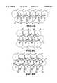
- FIGS. 10A and 10Bare diagrams illustrating alternative distribution architectures for the data communications system of the present invention.
- FIG. 11is a block diagram illustrating a time delay compensation module within the data communications system of the present invention.
- the present inventionprovides an economical solution to the problem of extending the coverage area of a data communications system for communicating data packets between remote terminals operating in a radio frequency (RF) environment and a host computer operating in a digital network environment.
- This extension of the communications coverage areais accomplished by connecting repeaters, also known as transmit/receive (T/R) modules, to a base station or access point for the transmission of incoming data from the remote terminals and outgoing data to the remote terminals.
- T/Rtransmit/receive
- the repeatersoperate as amplifiers, the overall coverage area of the data communications system can be extended without the installation of another base station. Consequently, the present invention provides an economical solution to the problem of extending the coverage of a data communications system because the acquisition and installation of repeaters is generally less expensive than the addition of another base station.
- the present inventionprovides a data communications system characterized by the combination of a base station, connected to repeaters, for communicating with (1) remote terminals in response to outgoing data from a host computer and (2) the host computer in response to incoming data from the remote terminals.
- a repeaterconducts a signal amplification operation and outputs amplified incoming data to the base station via a first communications link.
- the base stationprocesses the amplified incoming data and, in turn, generates processed incoming data for distribution to the host computer via a second communications link.
- the base stationalso processes the outgoing data from the host computer to generate processed outgoing data, and sends transmitted outgoing data to each repeater via the first communications link.
- Each repeatercan amplify the transmitted outgoing data, and outputs amplified outgoing data to the remote terminals within its coverage area.
- An “access point”facilitates radio coverage for a given area by enabling a wireless network to access a wired network for data communications.
- the access pointalso known as a base station, typically serves as an intermediary between the wireless network and the wired network.
- the wired networkis a local area network (LAN)
- an access pointserves as a "bridge” spanning the wireless and wired networks, and operates at the Data Link Layer (Layer Two) of the OSI Network Model.
- Access pointscan function as a MAC-layer bridge for making binary-level decisions regarding whether to forward packets of information between the wireless and wired networks. Consequently, access points are generally viewed as being network and transport protocol independent.
- a “remote terminal”is a radio transceiver characterized by an antenna, a radio receiver for receiving data via the antenna, and a radio transmitter for transmitting data via the antenna.
- the remote terminalfurther includes a computer for processing data and one or more input devices, connected to the computer, for supplying data to be transmitted by the transceiver to a central site.
- a remote terminalcan be used for either fixed or mobile communications, the typical application for a remote terminal is as a portable data collection device for collecting data from a remote source and communicating the collected data to a central location.
- Spread spectrumis a radio communications technique used by real-time RF data communications systems, such as Business Radio Systems.
- a spread spectrum radio signalrepresents information that is dynamically spread over a relatively wide bandwidth rather than centered within a narrow band of a fixed carrier frequency.
- Spread spectrum communicationsrequire the receiver to have knowledge of the frequency spectrum spreading technique employed by the transmitter to allow the receiver to perform a complementary operation for retrieving information from the received signal.
- a "direct sequence spread spectrum (DSSS) communications system”transmits a fixed frequency carrier signal modulated by a modulating signal formed by the combination of a data stream multiplied by a pseudo-random sequence, commonly called a "chip code”. Because the pseudo-random bit sequence has statistics that approximate noise, the transmitted signal looks like broadband noise with only a relatively nominal power peak centered at the carrier frequency.
- DSSSdirect sequence spread spectrum
- a “frequency hopping spread spectrum (FHSS) communications system”transmits information by “hopping” from one carrier frequency to another carrier frequency. This change in carrier frequencies is defined by a frequency hopping sequence, which describes the set of carrier frequencies, the hop period, and the hop pattern.
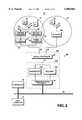
- FIG. 1is block diagram illustrating a data communications system embodying the present invention.
- a data communications system 10includes a base station 12, coupled to a host computer 14 and to a controller 15, for communicating with remote terminals 16 via a set of repeaters 18.
- Each repeater 18has a coverage area 20 and the combination of all coverage areas 20 define a predetermined area 22. Adjacent coverage areas 20 preferably overlap so that each portion of the predetermined area will be located within the coverage area of at least one of the repeaters 18.
- a remote terminal 16can exchange data packets with host computer 14 via the communications "bridge" supplied by the base station 12 when the remote terminal is located within one of the coverage areas associated with the repeaters 18.
- a remote terminal 16 within the predetermined area 22transmits a radio signal containing incoming data.
- Each repeater 18includes an antenna 24 for transmitting and receiving radio signals within its coverage area 20. Consequently, the radio signal emitted by the remote terminal 16 is received by a repeater 18 having the coverage area 20 in which the signal source is located.
- the repeater 18"repeats" the radio signal supplied via the antenna 24 by amplifying the incoming data to generate amplified incoming data.
- the repeater 18then outputs the amplified incoming data via a first communications link 26 connected between the repeater 18 and the base station 12.
- Each of the repeaters 18is connected to the base station by a bidirectional communications path supplied by the communications link 26.
- the base station 12which is connected to each first communications link 26 and to a second communications link 36, includes a signal processor 28, a transceiver 30, and a communications interface 34.
- the transceiver 30,which comprises a radio receiver 31 and a radio transmitter 33, is connected to the signal processor 28 via a signal path 32.
- the communications interface 34which is connected between the transceiver 30 and the second communications link 36, is primarily responsible for handling the different signal protocols or formats associated with transferring signals from one communications media to another.
- the second communications link 36which is preferably implemented by a computer network, supports a bidirectional exchange of data packets among the base station 12, the host computer 14, and the controller 15.
- the signal processor 28which is coupled between each first communications link 26 and the signal path 32, accepts a signal representing the amplified incoming data output by the repeater 18. In similar fashion, the signal processor 28 can accept signals from the remaining repeaters of the data communications system 10 because the signal processor 28 is connected by a first communications link 26 to each of these repeaters.
- the combination of coverage areas 20define the predetermined area 22. As shown in FIG. 1, the base station 12 is typically located outside of the predetermined area 22. Consequently, the components of the base station 12, including the signal processor 28, the receiver 31, the transmitter 33, and the communications interface 34 are also positioned outside of the predetermined area 22 formed by the coverage areas 20.
- the signal processor 28passes the amplified incoming data to the transceiver 30 via the signal path 32 for detection by the receiver 31.
- the signal processor 28can operate as a signal combiner by combining all signals output from the communications links 26 to generate a summed signal for distribution via the signal path 32.
- the signal processor 28can operate as a signal divider by accepting a signal from the transceiver 30 and dividing this signal for distribution to each of the first communication links 26. Consequently, it will be appreciated that the signal processor 28 performs the functions commonly associated with a conventional RF component, a signal combiner/divider.
- the transceiver 30accepts the amplified incoming data from the signal processor 28 and, in response, the receiver 31 generates a detected signal representing detected incoming data.
- the communications interface 34responds to the detected incoming data by producing processed incoming data.
- the communication interface 34preferably converts the detected incoming data to a signal protocol or format that is appropriate for communicating this signal to the host computer 14 via the second communications link 36. This conversion operation is useful for converting the signal format of the incoming data passed by the communications link 26, typically a radio signal, to another signal format associated with the communications link 36.
- the communications interfaceoutputs the processed incoming data to the host computer 14 via the communications link 36. In this manner, one of the remote terminals 16 can send incoming data to the host computer 14 by routing the data via a repeater 18, the base station 12, and the communication links 26 and 36.
- the communications interface 34also accepts outgoing data, which is generated by the host computer 14 and distributed to the base station 12 via the second communications link 36. Similar to the conversion operation conducted for incoming data, the communications interface 34 processes the outgoing data to generate processed outgoing data. In particular, the communications interface 34 converts the outgoing data from a signal having a format associated with the second communications link 36 to a signal with a format associated with the first communications link 26. The communications interface 34 outputs the processed outgoing data to the transmitter 33 which, in turn, sends transmitted outgoing data to the signal processor 28 via the signal path 32. The signal processor 28 routes the transmitted outgoing data to each of the communications links 26 for delivery to the repeaters 18.
- each repeater 18"repeats" the transmitted outgoing data by generating an amplified signal representing amplified outgoing data. In this manner, the amplified outgoing data is transmitted to each of the repeater terminals 16 within the coverage areas 20 of the repeaters 18.
- the host computer 14serves as a central site for receiving and processing incoming data and for generating outgoing data intended for subsequent transmission to the remote terminals 16.
- the remote terminals 16are the primary source of incoming data, whereas the host computer 14 is the primary source of outgoing data.
- Incoming datatypically represents data collected by the remote terminals 16 or status information regarding the operation of these devices.
- outgoing datagenerally represents commands for controlling the operation of the remote terminals 16.
- the controller 15generally directs the flow of incoming data to the host computer 14 and outgoing data from the host computer 14. For example, the controller 15 can forward data packets from the base station 12, as well as from other devices on the communications link 36, to the host computer 14. Furthermore, the controller 15 can accept data packets from another device on the communications link 36, such a terminal, and forward this data to the base station 12 for eventual transmission to the remote terminals 16.
- the network controller 15is arranged so that it makes each of the remote terminals 16 appear as if these RF devices were "smart" terminals connected to the host computer 14.
- the pair of coverage areas 20 shown in FIG. 1slightly overlap to create an overlap area 40. It is desirable to create this overlap area to insure that communications between remote terminals 16 and the base station 12 are maintained when mobile terminals move from coverage area to the next.
- the data communications system 10is preferably implemented as a spread spectrum communications system for servicing a Business Radio System application.
- the preferred techniqueis a frequency hopping spread spectrum (FHSS) operation that increases the reliability of communications by decreasing the amount of interference to and from various users of the RF spectrum.
- FHSSfrequency hopping spread spectrum
- DSSSdirect sequence spread spectrum
- the FHSS technique"hops" from carrier frequency to carrier frequency at a specified interval.
- the transceiver 30can be assigned a particular frequency hopping sequence that defines a set of discrete "hop" frequencies or channels, a time period between frequency hops, and a predetermined frequency hop sequence.
- the remote terminals 18are synchronized with the frequency hopping sequence assigned to the transceiver 30 to permit data communications between the base station 12 and the remote terminals 16 within the predetermined area 22. Consequently, it will be appreciated that each of the coverage areas serviced by a particular base station will be associated with the same frequency hopping sequence.
- the present inventioncan encompass the use of more than one base station 12, each having a corresponding set of repeaters 18, to construct a data communications system.
- a remote terminal 16enters a predetermined area 22 associated with another base station 12
- this remote terminalcan sync-up with the required frequency hopping sequence by (1) entering a hunt mode and (2) waiting on a frequency of a particular channel-until it receives a synchronization signal associated with that base station 12.
- This synchronization operationis described in U.S. Pat. No. 5,287,384 entitled "Frequency Hopping Spread Spectrum Data Communication System", issued Feb. 15, 1994.
- U.S. Pat. No. 5,287,384is hereby incorporated by reference.
- this "park and wait" synchronization processrequires the remote terminal to tune to one of several predetermined "home” channels and wait on the selected home channel until the base station transmits on this selected home channel in response to its predetermined frequency hopping sequence.
- the base stationtransmits on the home channel a data sequence that supplies required synchronization information, such as the frequency hopping pattern and timing marks.
- the remote terminalcan adapt its transmit and receive operations to maintain synchronized operations with the base station.
- the remote terminalwhen the remote terminal enters a predetermined area for another base station, the remote terminal can scan all possible channels to look for a master radio signal with a known channel identification message containing the frequency hopping pattern and timing marks for the base station. In response to the detecting the master radio signal, the remote terminal obtains the required synchronization information. It will be appreciated that this synchronization operation requires the base station to repeat the channel identification message for sufficient time intervals to allow a remote terminal to scan all possible channels to acquire the master radio signal.
- each of the base stations 12preferably implement a spread spectrum arrangement complying with Part 15 of the Rules of the Federal Communication Commissions of the United States of America. Part 15 of these regulations, as they exist as of the filing date of this application, are hereby incorporated by reference.
- the preferred base station 12complies with the regulatory limitations for an intentionally radiating Business Radio System that is a low power communications device under Sub-part D of Part 15 of the FCC Regulations. Nevertheless, those skilled in the art will appreciate that the present invention is not limited to Business Radio System applications, but can be extended to other communications applications in different frequency ranges.
- regulatory limitationsdefine the minimum number of discrete frequencies or channels, the maximum dwell time per channel, the maximum channel spacing, and the maximum 6 dB bandwidth.
- the minimum discrete channels or frequenciesmust be at least seventy-five hopping frequencies.
- the maximum dwell time per channelis 400 milliseconds for any 30 second period.
- the maximum twenty dB bandwidth of the hopping channelis one MHz.
- the maximum peak output power of the transmittershould not exceed one Watt.
- the minimum channel spacingmust be the larger of either 25 kHz or the dB bandwidth of the hopping channel.
- Each hopping frequencymust be used equally on the average by each transmitter. Similar FCC regulatory requirements exist for the other Business Radio System bands, including the 900 MHz and 5.8 GHz bands.
- the first communications link 26is implemented by a bidirectional transmission device, such as a coaxial cable
- the second communications link 36is implemented by a wired computer network, such as a LAN.
- the communications link 26can transport radio signals, such as RF signals or intermediate frequency (IF) signals, between the repeaters 18 and the base station 12.
- the communications link 26can carry high-speed digital signals between the repeaters 18 and the base station 12.
- the communications link 36preferably operates within a client/server computing environment. Consequently, the base station 12 provides a bridge spanning a RF communications path and a wired network. This RF communications path includes the wireless link between a remote terminal 16 and a repeater 18, and the wired link between the repeater 18 and the base station 12.
- the base station 12preferably reformats the RF Data Link layer protocol of the incoming data into an IEEE 802.3 ETHERNET standard protocol to support the forwarding of the data packet via the LAN. A similar operation is performed by the base station 12 to support the forwarding of outgoing data from the LAN to the bidirectional transmission device.
- the base station 12is protocol independent because this device functions independently of the network layer (OSI layer 3), the transport layer (OSI layer 4), and other protocols operating above these OSI model layers.
- the host computer 14preferably communicates with the base station 12 by use of the IEEE 802.3 ETHERNET standard protocol, it will be appreciated that other conventional protocols can be employed in systems embodying the present invention.
- ETHERNET protocol and associated network hardwareis well known.
- the communications link 36can be implemented by other local area or wide area network architectures for supporting the data communications system embodying the present invention.
- the controller 15typically operates as a server within a client/server environment to service the communications needs of the host computer 14 and for providing services to the various terminals connected to the wired computer network.
- the controller 15operates to route data packets from the host computer 14 to the base station 12 or to the terminals connected to the LAN.
- the controller 15also can route data packets from the base station 12 to the host computer 14 or to terminals on the LAN.
- the controller 15is responsible for routing data packets to and from the appropriate base station. In this manner, the host computer 14 can view the remote terminals 16 as if they were terminals directly connected to either the computer or to a standard terminal controller device.
- the remote terminals 16are preferably implemented by the combination of a radio transceiver and a microprocessor-based personal computer.
- the radio transceiver of the remote terminal 16supports communications with the base station 12.
- the computercan control the operation of the remote terminal 16 and support the collection and storage of data from a remote site.
- the radio transceiver of the remote terminal 16is a spread spectrum communications device, preferably using the FHSS technique.
- the remote terminal 16further includes an antenna, such as an omni-directional antenna, connected to the radio transceiver to support data communications.
- the computer of the remote terminal 16can be connected to a variety of input devices. These input devices include keyboards or keypads, bar code scanners, and display screen touch-sensitive buttons. It will be understood that the input device connected to the computer of the remote terminal 16 is defined by the particular data collection application. For example, inventory applications within a warehouse typically use a bar code scanner or on-screen touch-sensitive buttons. To support user operation of the remote terminal 16, as well as to display collected data, the remote terminal 16 also can include an output device, such as a liquid crystal display (LCD) monochrome display or a color display device. The output device is useful for displaying outgoing data received by the remote terminal 16 and results of local operation of the input device.
- LCDliquid crystal display
- the remote terminal 16can be implemented as a fixed communication devices or as a roaming or mobile communication device. If mobile, the remote terminals 16 can freely roam about the physical locations of the data communications system 10 by moving from one coverage area of a repeater 18 to another repeater's coverage area. Consequently, communications between the remote terminal 16 and the base station 12 can occur so long as the remote terminals 16 remain within the predetermined area of the data communications system 10.
- the remote terminals 16can be implemented by the Model 1330 Explorer or the Model 2320 Scout, both available from LXE, Inc. of Norcross, Ga.
- the Model 1330 Explorerincludes a model 486-compatible microprocessor, up to 4 megabytes of random access memory (RAM), a monochrome LCD display, and a communication port for connecting an input device, such a powered bar code scanner.
- a keyboardcan be connected to the Model 1330 Explorer for controlling the terminal and for inputting data.
- the Model 1330 Explorercan employ the FHSS technique in either the 900 MHz or the 2.4 GHz bands.
- the data rate for the 2.4 GHz bandis 1.6 Mbps
- the data rate for the 900 MHz bandis 64 Kbps.
- the combination of the transceiver 30 and the communications interface 34 in the base station 12can be implemented by a Model 6410 OmniNet Access Point available from LXE, Inc.
- the Model 6410includes an ETHERNET interface for supporting an industry standard computer network and is compatible with the IEEE 802.3 ETHERNET standard.
- the Model 6410includes a transceiver capable of operation within the frequency band of 2.4-2.4835 GHz and employs a frequency hopping spread spectrum communications technique.
- the repeaters 18operate to reproduce the data signals transmitted by the base station 12 and the remote terminals 16.
- the simple addition of another repeater to the data communications system 10supports the extension of the overall coverage area of the system.
- data communications systemswere limited to the coverage area associated with a single base station.
- the solution presented by the present invention for extending communications coverageis cost effective because the addition of a repeater is less costly than the addition of another base station.
- repeaters with a single base stationcan be accomplished without requiring mobile remote terminals to exchange "roaming" control information with the base station.
- the exchange of roaming control informationis not required for the architecture of a single base station and multiple repeaters/coverage areas because all coverage areas have the same predetermined frequency hopping sequence.
- a data communications system 10aincludes a set of repeaters 18a, each including a converter 50 for converting the frequency range of the outgoing data signals and the incoming data signals.
- Each converter 50includes a down-converter 52 and an up-converter 54.
- the down-converter 52conducts a frequency down-conversion operation to shift the frequency of an incoming data signal from the RF range to an IF range.
- the up-converter 54conducts a frequency up-conversion operation by shifting the IF range of an outgoing data signal to an RF range.
- the down-converter 52 and the up-converter 54can be implemented by the conventional combination of a mixer connected to a local oscillator.
- the remote terminals 16typically transmit and receive signals within the RF range of the frequency spectrum, such as the frequency bands allocated for Business Radio System applications. Consequently, the repeaters 18a can accept the RF signals from the remote terminals 16 and pass RF signals to the remote terminals 16.
- the down-converter 52supports the distribution of IF signals from a repeater 18a to a base station 12a and to the repeater 18a from the base station 12a. Accordingly, the communications link 26 carries an IF signal rather than an RF signal during the transfer of data between a repeater 18a and the base station 12a.
- Thisprovides the advantage of reducing signal losses resulting from distribution of data via a physical media, such as a coaxial cable or a twisted-pair cable, because cable losses are generally reduced as the frequency range decreases.
- This reduction of cable losses by the distribution of IF signals rather than RF signalsis significant because signal gain can be achieved at both ends of the communications link 26, i.e., the base station 12a and the repeater 18a.
- An advantageis gained by the half-duplex operation of the data communications system 10a because the signal path for forwarding outgoing data from the base station 12a to the repeater 18a is identical to the signal path for forwarding incoming data from the repeater 18a to the base station 12a.
- the repeater 18aincludes a receive path 56 and a transmit path 58, each path connected between the antenna 24 and the communications link 26.
- the receive pathincludes the down-converter 52 and a receive amplifier 60
- the transmit path 58includes the up-converter 54 and a transmit amplifier 62.
- the receiver amplifier 60amplifies incoming data supplied from the remote terminals 16 via the antenna 24 and outputs amplified incoming data.
- the amplified incoming datarepresents an amplified version of the incoming data transmitted by a remote terminal 16. Consequently, the receive amplifier 60 outputs an RF signal to the down-converter 52 which, in turn, conducts a down-conversion operation to generate an IF signal representing the amplified incoming data.
- the up-converter 54receives an IF signal representing transmitted outgoing data, and conducts an up-conversion operation to generate an RF signal.
- the transmit amplifier 62amplifies the RF signal representing transmitted outgoing data and outputs amplified outgoing data.
- the base station 12acan include a transceiver 30a capable of transmitting and receiving IF signals onto the first communications link 26.
- the transceiver 30aaccepts an IF signal of incoming data from a signal processor 28 and, in response, generates detected incoming data.
- the transceiver 30aalso transmits an IF signal of outgoing data in response to processed outgoing data supplied by the communications interface 34. It will be understood that the transceiver 30a performs functions similar to those of the transceiver 30 described with respect to FIG. 1, with the exception that the transceiver 30a conducts transmit and receive operations upon IF signals rather than RF signals.
- a remote terminal 16which is operating in a spread spectrum mode, transmits an RF signal of incoming data within the predetermined area 22.
- a repeater 18a for the coverage area 20 in which the remote terminal 16 is locatedreceives this RF signal and passes it from the antenna 24 to the receive amplifier 60.
- the receive amplifier 60outputs an amplified version of the RF signal of incoming data to the down-converter 52.
- the down-converter 52responds by converting the RF signal of the incoming data to an IF signal of incoming data.
- the down-converter 52then outputs this IF signal to the base station 12a via the communications link 26. In this manner, an IF signal is carried by the communications link 26 rather than the RF signal previously described with respect to FIG. 1.
- the signal processor 28which is connected to the other end of the communications link 26, receives the IF signal of incoming data at the base stations 12. In response, the signal processor 28 forwards this IF signal to the transceiver 30a via the signal path 32.
- the transceiver 30awhich includes a radio receiver 31a capable of detecting IF signals, outputs a detected version of the IF signal of incoming data.
- the receiver 31asupplies the detected incoming data to the communication interface 34.
- the communications interface 34processes the detected incoming data, and thereafter outputs processed incoming data to the host computer 14 via the communications link 36.
- the communications interface 34 shown in FIG. 2also accepts outgoing data from the host computer 14 for subsequent transmission to the remote terminals 18.
- the communications interface 34converts the outgoing data from a protocol compatible with network transmissions carried by the communications link 36 to a protocol compatible with radio transmissions supported by the communications link 26.
- the transmitter 33a of the transceiver 30aoutputs an IF signal of outgoing data to the signal processor 28 via the signal path 32.
- the signal processor 28routes the IF signal of outgoing data to the communication links 26 connected to the repeaters 18a.
- Each repeater 18areceives the IF signal of outgoing data at the opposite end of the first communications link 26.
- This IF signalis passed to the up-converter 54 for shifting the carrier frequency range from the IF range to the RF range.
- the up-converter 54converts the IF signal of outgoing data to an RF version of the outgoing data.
- the transmit amplifier 62accepts the RF signal of outgoing data and, in turn, generates an amplified version of this signal.
- the amplified outgoing datais output by the transmit amplifier 62 to the antenna 24 for distribution to the remote terminals 16 within the predetermined area 22. It will be understood that the up-conversion operation performed by the repeater 18a facilitates the forwarding of the RF signal of outgoing data to repeaters 16 within its coverage area.
- the transceiver of the base station 12 (FIG. 1) and the base station 12a (FIG. 2)can be implemented by a frequency synthesizer capable of frequency hopping operations to generate the required frequency carriers and modulation operations for modulating these frequency carriers.
- a frequency synthesizercapable of frequency hopping operations to generate the required frequency carriers and modulation operations for modulating these frequency carriers.
- the frequency synthesizershould respectively cover bandwidths of approximately 28 MHz, 83 MHz, and 150 MHz.
- each frequency carrierhas a bandwidth of 250 kHz; the 2.4 GHz band, each frequency carrier has a bandwidth of 1 MHz; and the 5.8 GHz band, each frequency carrier has a bandwidth of 2 MHz.
- These carrier bandwidthsare defined by the preferred FHSS mode.
- FIG. 3is a block diagram illustrating an alternative embodiment for the base station of a data communications system. Unlike the base station 12a of FIG. 2, FIG. 3 shows a base station 12b having a transceiver that transmits and receive RF signals rather than IF signals. Accordingly, to achieve the reduced signal losses offered by passing IF signals via the communications link 26, a conversion system is added between the transceiver 30 and the signal processor 28. Referring to FIGS. 2 and 3, the base station 12b comprises the signal processor 28, the transceiver 30, the communications interface 34, and the converter 70.
- the converter 70which is connected between the signal processor 28 and the transceiver 30, includes an up-converter 72 and a down-converter 74 for conducting frequency conversion operations to shift the frequency of signals distributed to and from the transceiver 30.
- the up-converter 72converts the RF signal of outgoing data from the transceiver 30 and generates an IF signal of outgoing data for distribution to the signal processor 28.
- the down-converter 74accepts the IF signal of incoming data from the signal processor 28 and, in response, outputs an RF signal of incoming data to the transceiver 30. Consequently, it will be appreciated that the up-converter 72 conducts up-conversion operations, whereas the down-converter 74 conducts down-conversion operations.
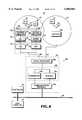
- FIG. 4is a block diagram illustrating a data communications system employing digital communications techniques for transporting data packets on the communications link between the base station and the repeaters.
- a data communications system 10cfeatures the exchange of digital data packets between a base station 12c and repeaters 18b via the communications link 26. This distribution of digital versions of incoming and outgoing data packets on the communications link 26 requires the inclusion within each repeater 18b of an analog-to-digital converter (ADC) and a digital-to-analog converter (DAC).
- ADCanalog-to-digital converter
- DACdigital-to-analog converter
- the frequency converter module 50is connected between an amplifier module 59 and a signal converter module 80.
- the amplifier module 59is connected to the antenna 24, whereas the signal converter 80 is connected to the first communications link 26.
- the amplifier module 59comprises the receive amplifier 60 and the transmit amplifier 62, each connected to the antenna 24.
- the frequency converter module 50can supply (1) an RF signal to the transmit amplifier 62 in response to an IF signal from the signal converter module 80 and (2) an IF signal to the signal converter 80 in response to an RF signal from the receive amplifier 60.
- the signal converter 80includes an ADC 82 and a DAC 84, each connected to the first communications link 26, for conducting signal conversion operations.
- the repeater 18bincludes both a receive path 56a and a transmit path 58a, each signal path connected between the antenna 24 and the first communications link 26.
- the receive path 56aincludes the down-converter 52, the receive amplifier 60, and the ADC 82
- the transmit path 58aincludes the up-converter 54, the transmit amplifier 62, and the DAC 84.
- RF signals transmitted by the remote terminals 16enter the receive path 56a via the antenna 24, and corresponding digital signals exit the receive path 56a and enter the communications link 26.
- digital signalsenter the transmit path 58a from the first communications link 26 and corresponding RF signals exit the transmit path 58a via the antenna system 24.
- RF signalsare distributed to and from the repeater 18b via the antenna system 24.
- digital signalsare distributed to and from the repeater 18b via the first communications link 26.
- the DAC 84accepts digital outgoing data from the base station 12c and, in response, converts the digital outgoing data to an analog signal format, i.e., an IF signal of outgoing data.
- the DAC 84outputs the IF signal of the outgoing data to the up-converter 54, which converts the IF signal to an RF signal.
- the transmit amplifier 64outputs an RF signal representing amplified outgoing data.
- the ADC 82converts the IF signal of incoming data from the down-converter 52 to a digital signal format, i.e., digital incoming data.
- the repeater 18bthen supplies the digital incoming data to the base station 12c via the first communications link 26.
- the base station 12cincludes a signal processor 28a, a transceiver 30b, and a communications interface 34a to support the exchange of digital signals with the repeaters 18b and the host computer 14.
- the signal processor 28awhich is connected to each of the communication links 26, can distribute digital signals in the form of digital data packets to and from the base station 12c. Specifically, the signal processor 28a passes digital incoming data from the first communication link 26 to the transceiver 30b. Likewise, the signal processor 28a forwards digital outgoing data from the transceiver 30b to each of the first communication links 26.
- the transceiver 30bwhich is connected between the signal processor 28a and the communications interface 34a, is preferably implemented by one or more digital signal processing modules to support the transmission and reception of digital data packets.
- a digital receiver 31b and a digital transmitter 33bare preferably implemented by digital signal processing modules to conduct the respective receive and transmit functions of the transceiver 30b.
- the communications interface 34ais adapted to accept digital data packets from the receiver 31b and to forward digital data packets to the transmitter 33b.
- a remote terminal 16outputs an RF signal containing incoming data within one of the coverage areas 20 of the predetermined area 22.
- the repeater 18b located within that coverage areareceives the incoming data via its antenna 24.
- the incoming datais processed by the components of the receive path 56a to supply a digital version of the incoming data to the first communications link 26.
- the receive amplifier 60accepts the RF signal of incoming data and, in turn, generates an amplified version of the incoming data.
- the down-converter 52outputs an IF version of the amplified incoming data by conducting a down-conversion operation.
- the ADC 82accepts the IF signal of incoming data and conducts an analog-to-digital conversion operation. This conversion operation produces a digital version of the IF signal of incoming data. Consequently, the ADC 82 outputs the digital incoming data to the base station 12c via the first communications link 26.
- the signal processor 28aaccepts the digital incoming data as an input signal. In turn, the signal processor 28a forwards the digital incoming data to the transceiver 30b.
- the receiver 31bwhich accepts the digital incoming data as an input signal, conducts a detection operation resulting in detected incoming data.
- the receiver 31boutputs the detected incoming data to the communications interface 34a for conversion from the digital data packet format associated with the first communications link 26 to the network protocol associated with the second communications link 36. This processed incoming data is then output by the communications interface 34a to the host computer 14 via the communications link 36.
- the communications interface 34aconverts the format of the outgoing data from one compatible with the communications link 36 to a format compatible with the communications link 26. This results in processed outgoing data, which is output by the communications interface 34a to the transceiver 30b.
- the transmitter 33bsends digital outgoing data to the signal processor 28a.
- the signal processor 28aforwards the digital outgoing data to the repeaters 18b via the communications links 26. In this manner, digital data packets of outgoing data are transmitted over the communication links 26 to the repeaters 18b.
- the DAC 84receives the digital outgoing data from the first communications link 26. In response, the DAC 84 conducts a digital-to-analog conversion operation, thereby generating an analog version of the digital outgoing data. Consequently, the DAC 84 outputs an IF signal of the outgoing data to the up-converter 54.
- the up-converter 54shifts the frequency range of the IF signal to the RF range, thereby generating an RF signal of outgoing data.
- the transmit amplified 62accepts the RF signal of outgoing data and, in response, generates amplified outgoing data.
- the transmitted outgoing datais forwarded to the remote terminals 16 within the coverage area 20 of the repeater 18b via the antenna 24.
- the exchange of digital format signals between the base station 12c and the repeaters 18bis useful because this digital signal format facilitates the application of conventional digital processing techniques upon these digital data packets.
- time delay compensation of each of the communication links 26can be conveniently accomplished by delaying the appropriate digital incoming and/or outgoing data packets by the appropriate number of clock cycles of the base station 12c.
- digital filtering techniquescan be advantageously applied to the digital incoming and outgoing data rather than analog filtering techniques.
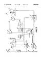
- FIG. 5is a block diagram illustrating the principal components of the preferred embodiment for the repeater 18.
- electrical poweris supplied by the base station 12 to each repeater 18 via a communications link 26.
- the communications link 26is also used to distribute control signals from the base station 12 to control the operating state of the repeater 18. These control signals determine whether the repeater 18 is operating in the transmit mode or in the receive mode by controlling the selection of either the transmit path or the receive path.
- the control signalsare also useful for biasing the amplifiers of the repeater 18 to allow the amplifier(s) within the selected path to be powered while the amplifier(s) in the remaining path are powered down.
- the preferred repeater 18is connected to the base station 12 by only a single bidirectional communications cable, the communications link 26, which is capable of distributing incoming and outgoing data packets, electrical power and control signals.
- the communications link 26is connected to a connection point 85 to link the base station 12 to the preferred repeater 18.
- a variable attenuator 88is connected to the connection point 85 via a direct current (DC)-blocking capacitor 86.
- One terminal of the DC-blocking capacitor 88is connected to the common node formed by the junction of a quarter-wave isolation device 90 and the connection point 85, and the remaining terminal is connected to the variable attenuator 88.
- outgoing data transmitted by the base station 12is passed to the variable attenuator 88 via the DC-blocking capacitor 86.
- amplified incoming datais passed by the variable attenuator 88 to the connection point 85 via the DC-blocking capacitor 86.
- the DC-blocking capacitor 86filters signals distributed between the connection point 85 and the variable attenuator 88 by blocking the DC components of these signals.
- the variable attenuator 88is useful for controlling the RF power level of the RF signals distributed by the repeater 18.
- a power signal, generated by the base station 12 and carried by the communications link 26,is supplied to (1) a voltage regulator 92 via the isolation device 90 and (2) a comparator 98 via a divider circuit formed by the combination of resisters 94 and 96.
- the isolation device 90prevents the RF signal of outgoing data or incoming data from reaching the control logic circuitry of the repeater 18 by filtering the RF signal components.
- the isolation device 90is preferably implemented as a quarter-wavelength transmission line.
- the voltage regulator 92accepts the power signal from the isolation device 90 and, in response, outputs a regulated power signal V 3 for powering the active devices of the repeater 18.
- the voltage regulator 92which is preferably implemented by a linear voltage regulator device, distributes the regulated power signal V 3 to the amplifiers in the receive path 56 and the transmit path 58.
- a bias switch 100which is connected between the output of the voltage regulator 92 and the power supply inputs of the amplifiers of the receive and transmit paths 56 and 58, controls the distribution of the regulated power signal V 3 to support selective biasing of the amplifiers.
- the divider circuitwhich is formed by the combination of the resistors 94 and 96, divides the voltage of the power signal in a predefined manner for input to the comparator 98.
- the resistor 94is connected between (1) a common node formed by the connection of the isolation device 90 and the input of voltage regulator 92 and (2) a common node formed by a terminal of the resistor 96 and the positive input port of the comparator 98.
- the remaining terminal of the resistor 96is connected to ground.
- the values of the resistors 94 and 96are selected to supply a predetermined voltage level to the positive input port of the comparator 98 in response to the level of the power signal.
- a reference voltage V REFis supplied to the remaining input port of the comparator 98.
- the comparator 98operates to compare the reference voltage V REF to the voltage applied to the positive input port. In the event that the voltage applied to the positive input port is greater than the reference voltage V REF , the data communications system 10 is operating in the transmit mode. In contrast, if the voltage at the positive input port is at or below the reference voltage V REF , then the data communications system 10 is operating in the receive mode.
- the power signal carried by the communications link 26is used by the repeater 18 (1) to determine whether the data communications system 10 is operating in the transmit state or the receive state and (2) to power to active circuitry of the repeater 18.
- the comparator 98outputs a control signal having one of two control states, a first control state representing the transmit mode and a second control state representing the receive mode.
- the comparator 98outputs a control signal having the first control state when the voltage applied to the positive input port is greater than the reference voltage V REF . In the event that the reference voltage V REF is less than or equal to the voltage applied to the positive input port, the comparator 98 generates a control signal having the second control state.
- the control signalis distributed by the comparator 98 to the bias switch 100, a switch 102, and a level detector unit 101.
- the variable attenuator 88which is connected between the DC-blocking capacitor 86 and the common port of the switch 102, can set the RF power level for signals supplied by the receive path 56 to be supplied to the transmit path 58.
- the variable attenuator 88can be used to simplify the installation of the repeater 18 by supplying a known amount of loss within the signal path between the base station 12 and the antenna 24.
- the switch 102operates to selectively connect the variable attenuator 88 either to the receive path 56 or to the transmit path 58.
- the switch 102is preferably implemented by a single pole, double throw switch.
- the receive path 56is connected to the variable attenuator 88 and the transmit path 58 remains disconnected from the attenuator 88. Otherwise, the switch 102 connects the transmit path 58 to the variable attenuator 88, and the receive path 56 is disconnected from the variable attenuator 88.
- the operating state of the switch 102is controlled by the particular state of the control signal output by the comparator 98.
- the wiper of the switch 102connects the output of the variable attenuator 88 to the transmit path 58.
- the switch 102responds to a control signal having the second control state (receive mode) by connecting the receive path 56 to the input of the variable attenuator 88.
- the transmit pathwhich includes a power amplifier 104, is connected between the normally open contact of the switch 102 and the circulator 106.
- the receive path 56is connected between the normally closed contact of the switch 102 and the circulator 106.
- the receive path 56includes a band pass filter 114 connected between a low noise amplifier 112 and a driver amplifier 116.
- the input of the low noise amplifier 112is connected to the circulator 106, whereas the output of the driver amplifier 116 is connected to the normally closed node of the switch 102.
- the power amplifier 104, the low noise amplifier 112, and the driver amplifier 116are selectively connected to the output of the voltage regulator 92 via the bias switch 100.
- the common port of the bias switch 100is connected to the regulated power signal V 3 supplied by the voltage regulator 92.
- the normally closed contactis connected to the low noise amplifier 112 and the driver amplifier 116, whereas the normally open contact is connected to the power amplifier 104.
- the bias switch 100connects the regulated power signal V 3 to the power supply input of the power amplifier 104.
- the bias switch 100connects the regulated power signal V 3 to the power supply inputs of the low noise amplifier 112 and the driver amplifier 116.
- a low pass filter 108is connected between the antenna 24 and the circulator 106.
- the circulator 106operates to direct the amplified outgoing data from the transmit path 58 to the antenna 24. In similar fashion, the circulator 106 directs the incoming data from the antenna 24 to the receive path 56. Both amplified outgoing data and incoming data are passed via the low pass filter 108 to filter undesired out-of-band frequency components, such as harmonic components.
- a coupler 110is connected between the antenna 24 and the level detector unit 101. During the transmit state, the coupler 110 can couple a portion of the amplified outgoing data to the level detector unit 101.
- the level detector unit 101accepts as inputs the control signal output by the comparator 98 and the coupled signal from the coupler 110, and outputs a control signal to control the attenuation level of the variable attenuator 88.
- the level detector unit 101functions as an automatic level controller for the repeater 18 by controlling the attenuation level of the variable attenuator 88.
- the variable attenuator 88can be used to attenuate the RF level of transmitted outgoing data, as required, to avoid driving the power amplifier 104 into a compression state.
- the variable attenuator 88can control the RF level of amplified incoming data to prevent driving the receiver 31 of the base station 12 into a saturation state.
- the level detector unit 101can determine whether the data communications system 10 is operating in the transmit or the receive state. In response to the control signal, as well as the detected power level of the signal coupled by the coupler 110, the level detector unit 101 sets the attenuation level of the variable attenuator 88.
- the level detector unit 101is preferably implemented by the combination of an envelope detector and a controller.
- the coupler 110samples the amplified outgoing data and supplies the coupled signal to the envelope detector.
- the envelope detectordetects the level of the coupled signal and outputs a detected signal to the controller.
- the controllerresponds to the detected level by determining the desired attenuation level based on information stored in look-up tables.
- the controllerthen outputs a control signal representing the desired attenuation level to the attenuator 88. Because the controller operates as a sample and hold circuit, the level detector unit 101 "holds" this control signal, until the controller outputs another control signal. Consequently, the level detector unit 101 can "hold” the value of the control signal during the receive state to insure that the attenuation level, originally set during the transmit state, remains constant during the receive state.
- the level detector unit 101supplies an automatic level control function for the repeater 18 by sampling the power level of the repeater's output during the transmit state and adjusting the attenuation level of the attenuator 88 (as required).
- the amplified outgoing datais sampled by the level detector unit 101 because signal level characteristics for the base station 12, the communications link 26, and the repeater 18 are known, whereas there exists an absence of advance knowledge about the link between the repeater 18 and a remote terminal 16. Consequently, adjustments of the attenuation level for the attenuator 88 are conducted by the level detector 101 only during the transmit state.
- the communications link 26carries outgoing data and an electrical power signal.
- the outgoing datarepresents the transmit signal of outgoing data from the transmitter 33, whereas the power signal is generated by a power source of the base station 12.
- the power signalserves dual functions, specifically a power function for powering the active circuitry of the repeater 18, and a control function for controlling the operating state of the repeater 18, i.e., transmit state or receive state.
- the transmit outgoing datais supplied by the communications link 26 to the variable attenuator 88 via the DC-blocking capacitor 86.
- the power signalis supplied by the communications link 26 to the control circuitry of the repeater 18 via the isolation device 90.
- the voltage regulator 92receives the power signal directly from the isolation device, whereas the comparator 98 receives the power signal via the combination of the resistors 94 and 96.
- the voltage regulator 92outputs the regulated power signal V 3 for powering each of the active devices of the repeater 18, specifically the power amplifier 104, the low noise amplifier 112, and the driver amplifier 116.
- the regulated power signal V 3provides the operating power for the control circuitry of the repeater 18. It will be appreciated that the voltage level for the power signal, which is supplied as an input to the voltage regulator 92, is greater than the voltage level of the regulated power signal V 3 output by the regulator 92.
- the comparator 98Based on the voltage level of the power signal, the comparator 98 outputs a control signal having one of two control states, a first state (transmit mode) or a second state (receive mode).
- the control signal output by the comparator 98is applied to the bias unit 100, the level detector unit 101, and the switch 102.
- the control signalcontrols the operating state of each of the switches 100 and 102 and advises the level detector unit 101 of the operating state of the repeater 18.
- the power signalhas a higher voltage level for the transmit state than for the receive state.
- the higher voltage level for the transmit stateis greater than the reference voltage V REF applied to the comparator 98. Consequently, in the transmit state, the comparator 98 outputs a control signal set to the first state.
- the variable attenuator 88passes the transmitted outgoing data to the common port of the switch 102.
- the common portis connected either to the receive path 56 or to the transmit path 58.
- the transmitted outgoing datais passed by the switch 102 to the input of the power amplifier 104.
- the power amplifier 104accepts the transmitted amplified data and, in turn, outputs an amplified version of this radio frequency signal.
- the power amplifier 104is biased to the "ON" state because the bias switch 100 is passing electrical power, the voltage V 3 , from the voltage regulator 92 to the power supply input of the power amplifier 104 in response to receipt of the control signal from the comparator 98. Because the bias switch 100 is operating in the transmit mode, the amplifiers of the receive path 56 do not receive electrical power from the voltage regulator 92. The low noise amplifier 112 and the driver amplifier 116 are "turned off” to prevent the likelihood of oscillation by the amplifiers of the receive path 56 and the transmit path 58 as a result of signal leakage.
- the circulator 106forwards the amplified outgoing data from the power amplifier 104 to the low pass filter 108.
- the low pass filter 108which filters the high frequency components of the amplified outgoing data, forwards a filtered version of the amplified outgoing data to the antenna 24.
- the low pass filter 108removes the undesired harmonic components of the amplified outgoing data prior to transmission of this RF signal to the repeaters 18 via the antenna 24.
- the coupler 110couples a sample of the amplified outgoing data from the output of the low pass filter 108.
- the coupled signalis supplied to the level detector unit 101 to facilitate the detection of the power level for the amplified outgoing data.
- the envelope detector of the level detector unit 101detects the power level of the coupled signal.
- the detected power levelis sampled by a sample and hold function provided by the controller of the level detector unit 101. Based on this sample, the controller determines whether to adjust the attenuation level of the variable attenuator 88. This decision is supported by look-up tables that list detected values for amplified outgoing data and corresponding attenuation levels for the variable attenuator 88.
- variable attenuator 88In response to a control signal from the level detection unit 101, the variable attenuator 88 sets a predetermined attenuation level for the repeater 18 to provide a known loss characteristic between the base station 12 and the repeater 18 regardless of the transmission medium used for the communications link 26. In this manner, the variable attenuator 88 can control the signal level entering the power amplifier 104, thereby enabling the selection of the proper drive level for the power amplifier 104 to obtain the desired output power level.
- the variable attenuation levelis set by the variable attenuator 88 during the transmit state and remains constant for the receive state.
- the repeater 18transitions from the transmit state to the receive state in response to a transition of the voltage level for the power signal supplied by the communications link 26.
- the comparator 98outputs a control signal having a second control state representing the receive mode.
- the wipers of the switches 100 and 102transition to the normally closed operating state.
- the switch 100connects the output of the voltage regulator 92 to the power supply input of each of the amplifiers 112 and 116 of the receive path 56.
- the switch 102connects the variable attenuator 88 to the receive path 56.
- This control signalalso serves to advise the level detector unit 101 that the data communication system has now entered the receive state.
- incoming datais received from the remote terminals 16 via the antenna 24.
- the incoming datais passed by the antenna 24 to the circulator 106 via the low pass filter 108.
- the circulator 106directs the incoming data from the low pass filter 108 to the input of the low noise amplifier 112.
- the low noise amplifier 112amplifies the incoming data and generates amplified incoming data.
- the amplified incoming datais filtered by the band pass filter 114 to remove out-of-band frequency components.
- the band pass filter 114provides a proper impedance match between the output of the low noise amplifier 112 and the input of the driver amplifier 116.
- the driver amplifier 116accepts the amplified incoming data and, in turn, generates a further amplified version of the signal. This allows the repeater 18 to drive the communications link 26 with a sufficient power level for proper reception of the amplified incoming data by the receiver 31.
- the output of the driver amplifier 116is supplied to the variable amplifier 88 via the signal path provided by
- the variable attenuator 88attenuates the amplified incoming data based on the selected attenuation level previously set during the transmit mode. Specifically, in the receive mode, the level detector unit 101 holds the attenuator 88 at the attenuation level used for the transmit state. Consequently, the attenuation level for the receive path 56 is identical to the attenuation level for the transmit path 58. The attenuated signal is forwarded by the variable attenuator 88 to the communications link 26 via the DC-blocking capacitor 86.
- the power amplifier 104is implemented as 40 dB power amplifier.
- the amplified outgoing datahas an RF power level of approximately +20 dBm.
- the low noise amplifier 112 and the driver amplifier 116supply at least 40 dB of gain in the receive path.
- the amplifiers 112 and 116can supply slightly more than 40 dB of gain in the receive path to overcome the loss characteristic of the front-end of the receiver 31 of the base station 12. By supplying slightly more gain in the receive path 56 than the transmit path 58, the signal reception performance of the base station 12 can be improved by slightly decreasing the noise characteristic for the receiver 31.
- the low-pass filter 108can be inserted between the power amplifier 104 and the circulator 106 to slightly improve the noise figure for the repeater 18. Specifically, the low-pass filter 108 is primarily used to filter harmonics generated in the transmit mode by the power amplifier 104. Consequently, the low-pass filter 108 can be inserted within the transmit path 58 rather than between the circulator 106 and the antenna 24 without decreasing performance in the receive path 56.
- FIG. 6is a block diagram illustrating the principal components of the preferred signal processors of the data communications system.
- the preferred signal processor 28is connected between the transceiver 30 and each first communications link 26.
- a common port 117 of the signal processor 28is connected to the transceiver 30 via the signal path 32.
- the communications links 26are connected to the signal processor 28 at the ports 118' and 118".
- the port 118'represents a throughput port, whereas the ports 118" represent divided ports.
- the through port 118'is connected to the common port 117 via a combination of couplers 120 and 122 and a DC-blocking capacitor 126.
- Each of the couplers 120 and 122sample signals traveling between the common port 117 and the through port 118' and respectively supply coupled signals to the transmit/receive detector 124 and to a signal combiner/divider 128.
- the divided ports 118"are connected to the signal combiner/divider 128 via DC-blocking capacitors 130.
- the DC-blocking capacitors 126 and 130respectively block DC-level signals from entering the RF circuitry of the signal processor 28.
- the transmit/receive detector 124is connected between a switch 132 and the coupled port of the coupler 120.
- the transmit/receive detector 124detects the operating state of the transceiver 30, i.e., whether the transceiver 30 is operating in the transmit state or in the receive state.
- the transmit/receive detector 124is preferably implemented as an envelope detector for detecting the level of the coupled signal supplied by the coupler 120.
- the envelope detector of the transmit/receive detector 124can detect the different levels associated with incoming and outgoing data and, in response, output a control signal having one of two distinct control states. If the base station 12 is operating in the transmit mode, then the control signal has a first control state representing the transmit mode.
- the control signalhas a second control state representing the receive mode.
- the control statescan be represented by the binary states of logical high and logical low levels.
- the first control statecan be represented by a logical high level and the second control state can be represented by a logical low level.
- the operating state of the switch 132is controlled by the control signal output by the transmit/receive detector 124.
- the common port of the switch 132is connected to the port 118' and each of the ports 118" via quarter-wave isolation devices 134.
- Each of the quarter-wave isolation devices 134prevent RF signals from entering the control circuitry of the power divider 28, while allowing DC-level signals to pass from the control circuitry to the ports 118' and 118".
- a voltage regulator 136is connected between a power source V IN and the normally open contact of the switch 132.
- a voltage regulator 138is connected between the power source V IN and the normally closed contact of the switch 132. Consequently, the wiper of the switch 132 can selectively connect the common port of the switch 132 either to the output of the voltage regulator 136 or to the output of the voltage regulator 138.
- the voltage regulator 136accepts an electrical power signal having a voltage V IN from the power source V IN and, in response, generates a regulated voltage V 1 .
- the voltage regulator 138outputs a regulated voltage V 2 in response to the electrical power signal output by the power source V IN .
- the voltage V INis greater than the voltage V 1
- the voltage V 1is greater than the voltage V 2 .
- Each of the voltages V IN , V 1 , and V 2is greater than the voltage V 3 of the repeater 18.
- the switch 132When the data communications system 10 is operating in the transmit mode, the switch 132 connects the output of the voltage regulator 136 to the through port 118' and the divided ports 118". In contrast, if the data communication system 10 is operating in the receive mode, then the output of the voltage regulator 138 is connected to the through port 118' and to the divided ports 118". Consequently, the voltage V 1 is associated with the transmit mode, whereas the voltage V 2 is associated with the receive mode.
- the voltage level supplied to the ports 118' and 118" via the switch 132determines whether the comparator 98 of the repeater 18 outputs a control signal representing the transmit mode or the receive mode. In contrast, the voltage regulator 92 of the repeater 18 outputs a regulated power signal V 3 regardless of whether the switch 132 passes the regulated voltage V 1 or the regulated voltage V 2 .
- the voltage level for the power signal output via the ports 118' and 118"determines whether the repeater 18 is operating in the transmit mode or the receive mode.
- the power signal output by the ports 118' and 118"is also used for powering the circuitry of the repeater 18.
- a single communications link 26can carry a RF signal associated with incoming or outgoing data, as well as transport the power signal for powering the repeater 18 and for controlling the operating state of the repeater 18.
- the through port 118'represents a throughput signal path between the common port 117 and the through port 118'. Consequently, the signal level for RF signals transported by this through path have a higher signal level than the RF signals coupled by the coupler 122 and subsequently divided by the signal combiner/divider 128. Specifically, for the embodiment shown in FIG. 6, the through path 118' has a path loss of approximately 1 dB, whereas each of the four divided paths between the signal combiner/divider 128 and the ports 118" has a path loss of approximately 17 dB. Thus, each of the divided ports 118" exhibit greater path loss than the through port 118'.
- the through port 118'can be connected to a communications link 26 having a much greater length than a communications link 26 connected to the divided port 118" because of the higher signal levels associated with the through port 118'.
- thisprovides an installer of the data communications 10 with increased flexibility by supporting the use of at least one extended cable between a selected repeater 18 and the base station 12.
- the transmitted outgoing datais passed from the signal path 32 to the common port 117 of the signal processor 28.
- the couplers 120 and 122couple a sample of the transmitted outgoing data for respective distribution to the transmit/receive detector 124 and to the signal combiner/divider 128.
- the transmit/receive detector 124determines that the data communications system 10 is operating in the transmit mode. Accordingly, the transmit/receive detector 124 outputs a first control signal representing the transmit mode to the switch 132.
- the switch 132connects the output of the voltage regulator 136 to each of the ports 118' and 118" via the quarter-wave isolation devices 134. In this manner, a power signal having the voltage V 1 is supplied to each of the communications links 26 connected to the ports 118' and 118" during the transmit mode.
- the coupler 122passes a sample of the transmitted outgoing data to the signal combiner/divider 128 which, in turn, outputs divided versions of the transmitted outgoing data to the ports 118".
- the through port 118'outputs the transmitted outgoing data supplied by the signal path 32, whereas the ports 118"'output divided versions of the transmitted outgoing data.
- Each of the ports 118' and 118"further output the power signal having the voltage V 1 to power the active circuitry of the repeater 18 and to select the transmit mode for the repeater 18.
- the ports 118' and 118"receive amplified incoming data via the communications link 26.
- the through signal path of the through port 118'forwards the amplified incoming data to the common port 117 via the DC-blocking capacitor 126, the coupler 122, and the coupler 120.
- the divided ports 118"pass the incoming amplified data via DC-blocking capacitors 130 to the signal combiner/divider 128.
- the amplified incoming data passed by the divided ports 118"are combined by the signal combiner/divider 128. This combined signal is then forwarded to the common port 117 via the coupler 122 and the through path of the coupler 120.
- the quarter-wave isolator device 90 of FIG. 5 and the quarter-wave isolator devices 134 of FIG. 6are preferably implemented by a microstrip design on a printed circuit board.
- the coupler 110 of FIG. 5 and the couplers 120 and 122 of FIG. 6are preferably implemented by microstrip designs on printed circuit boards.
- FIGS. 7A, 7B, and 7Care block diagrams illustrating alternative embodiments for a repeater of the data communications system for the present invention.
- FIG. 7Ais a block diagram illustrating the use of switches for switching between the receive and transmit paths of a repeater.
- FIG. 7Bis a block diagram illustrating the use of circulators for switching between the-receive and transmit paths of a repeater.
- FIG. 7Cis a block diagram illustrating a hybrid approach for switching between the receive and transmit paths of the repeater, namely the use of both a switch and a circulator.
- the repeater 18concludes a receive path 56 and a transmit path 58 connected between a first switch 140 and a second switch 142.
- the first switch 140which is connected to the first communications link 26 can operate in a pair of operating states. For the first operating state, the switch 140 connects the communications link 26 to the input of the transmit amplifier 62. In contrast, for the second state, the switch 140 connects the communications link 26 to the output of the receive amplifier 60.
- the switch 142also has two separate operating states, a first state for connecting the antenna 24 to the output of the transmit amplifier 62 and a second operating state for connecting the antenna 24 to the input of the receive amplifier 60.
- the switches 140 and 142operate in the first operating state to connect the transmit path 58 between the communications link 26 and the antenna 24.
- the switches 140 and 142operate in the second operating state to connect the receive path 56 between the antenna 24 and the communications link 26.
- control of the operating states for the switches 140 and 142can be implemented by supplying control signals from the base station 12 to repeater 18 via a control link.
- control signalscan be supplied by the base station 12 to the repeater 18 via the communications link 26.
- an internal detection systemcan be employed to allow a repeater 18 to detect the source of the signal to be repeated, thereby eliminating any requirement for a control link between the base station 12 and the repeater 18.
- circulators 144 and 146are connected between the receive path 56 and the transmit path 58.
- a circulator 144is connected to the first communications length 28 and between the input of the transmit amplifier 62 and the output of the receive amplifier 60.
- the circulator 146is connected to the antenna 24 and the input of the receive amplifier 60 and the output of the transmit amplifier 62.
- the circulator 144operates to pass this signal to the transmit path 58.
- the circulator 146responds to the amplified outgoing data by passing this signal to the antenna 24.
- the circulator 146also responds to incoming data forwarded by the antenna 24 by distributing this signal to the receive path 56.
- the circulator 144accepts the amplified incoming data and forwards this signal to the communications link 26.
- the switch 140 and the circulator 146are used to provide a hybrid approach for signal distribution within the repeater 18.
- the switch 140operates in the first operating state to forward outgoing data to the transmit path 58.
- the circulator 146directs the amplified outgoing data to the antenna 24 for transmission to the remote terminals 16.
- the circulator 146also accepts incoming data from the antenna 24 and routes this signal to the receive path 56.
- the switch 140operates in the second state to forward amplified incoming data from the receive amplifier 60 to the communications link 26.
- the switch 140requires a control mechanism for controlling the operating state of this switch.
- the circulator 146is a passive device requiring no active control mechanism.
- a variety of antennascan be used to implement the antenna system 24 of the repeater 18.
- the selection of a particular antenna for the repeater 18is based on the specific application and the actual implementation of the data communications system 10.
- a repeater 18can be mounted along a ceiling of a building to maximize the coverage area for this in-building environment.
- the antennais preferably a down-tilt model for which the primary lobe of the antenna pattern is directed at an angle toward the floor of the building.
- the tilt angle of the primary lobecan extend 45 degrees or more below the base level defined by the ceiling.
- Other antennascan have omni directional pattern, a cartoid antenna pattern, or a sectored antenna pattern.
- the polarization of the antenna 24can be vertical polarization, horizontal polarization, or a combination of these polarizations.
- the antenna system 24can be implemented by a pair of antennas, specifically a receive antenna for the receive path and a transmit antenna for the transmit path.
- Polarization diversitycan be achieved by the use of separate antennas for the transmit and receive paths of the repeater 18 because a particular polarization can be selected for one path and the opposite polarization can be selected for the remaining path.
- the antenna system 24also can be implemented as an antenna having circular polarization.
- each repeater 18contains one or more amplifiers.
- the repeaters 18can be powered by conventional DC or alternating current (AC) electrical power sources. As shown in FIGS. 5 and 6, DC power can be distributed to the repeaters 18 via the communications link 26 or, alternatively, by a separate power link. Likewise, AC electrical power can be distributed via the communications link 26 or by a separate power link.
- local power sourcescan be used by each repeater 18, such as a solar cell or a battery, to power the active device(s) of the repeater 18. If a battery is used to power the repeater 18, then a trickle charge design is preferably used to conserve the useful lifespan of the battery.
- FIGS. 8A-8Dare diagrams illustrating various communications applications of the present invention.
- FIG. 8Ashows the use of a single base station 12 connected to multiple repeaters 18, each having its own coverage area.
- the combined coverage areasform the predetermined area 22 for communications between the base station 12 and the remote terminals 16.
- Each of the coverage areas 20has the same frequency hopping sequence because each of the repeaters 18 is connected to the same base station.
- This base station 12has a particular frequency hopping sequence that is effectively "repeated" by the repeater 18 within their respective coverage areas 20. Consequently, a roaming remote terminal can move from one coverage area 20 to the next with minimal impact upon communications with the base station 12 because the frequency hopping sequence remains the same in all coverage areas.
- adjacent coverage areasslightly overlap and share a common overlap area 40.
- the inventorshave determined that the combination of transmitted signals within an overlap region of coverage areas can result in possible constructive and destructive interference effects that interfere with proper reception of the signal. These interference effects are a result of the use of the same predetermined frequency hopping sequence for communications between the base station 12 and the remote terminals 16 in each of the coverage areas 20. For example, there exists the possibility that signals output by the repeaters 18 for the coverage areas sharing the overlap area 40 will have the same frequency and be received by the remote terminal 16 at or about the same time.
- This combination of a pair of simultaneously transmitted signals within the overlap regioncan result in the remote terminal receiving an outgoing data signal having a deep null because of the equal or near equal amplitude and opposite phase characteristics of the transmitted signals.
- a compensation techniquecan be used to minimize this interference effect by compensating for the variation of electrical lengths of the communication links 26 extending between the base station 12 and the repeaters 18. Various compensation techniques will be described in more detail below with respect to FIG. 11.
- FIG. 8Bis a diagram illustrating the coverage areas formed by three separate base stations, each connected to their own set of repeaters, to form a data communications system. Each of these base stations has its own unique frequency hopping sequence. Accordingly, the set of coverage areas 20 for a particular base station is associated with the particular frequency hopping sequence of that base station. Although neither the base stations nor their respective repeaters are shown in FIG. 8B (or FIGS. 8C and 8D), it will be understood that the frequency hopping sequence for transmissions occurring within the coverage areas 20 identified by the number "1" is different from the frequency hopping sequence for transmissions within the coverage areas 20 identified by the numbers "2" and "3". The transmissions occurring within each set of coverage areas identified by a particular number are associated with a unique frequency hopping sequence because the frequency hopping sequences among these base stations are different.
- Adjacent coverage areasare associated with different base stations to prevent the simultaneous transmission of frequency carriers having the same frequency within an overlap area 40. This reduces the possibility for interference caused by the simultaneous reception of two or more transmitted signals having the same frequency carrier, equal or near equal amplitudes, and opposite phase characteristics. Significantly, coverage areas identified by the same reference number, i.e., those coverage areas representing the same frequency hopping sequence, are not placed adjacent to each other to minimize the possibility of constructive and destructive interference effects within the resulting overlap area 40.
- the coverage areas 20 identified by the number "1"are associated with the first base station; the coverage areas 20 marked by the number “2" are associated with the second base station; and the coverage areas 20 marked by the number “3” are associated with the third base station.
- the frequency coverage pattern illustrated in FIG. 8Bprevents the simultaneous transmission of frequency carriers having the same frequency within adjacent coverage areas, thereby reducing the possibility for interference within the overlap areas 40.
- FIG. 8Cis a diagram illustrating the set of coverage areas formed by the use of four separate base stations, each connected to their own set of repeaters, to form a data communications system.
- Each of the coverage areas 20 in FIG. 8Cis identified by a number associated with its corresponding base station 12 (and the corresponding set of repeaters 18).
- the coverage areas 20 identified by the number "1"are associated with a first base station
- the coverage areas 20 marked by the number "2"are associated with a second base station
- the coverage areas 20 marked by "3"are associated with a third base station
- the coverage areas 20 identified by the number "4"are associated with a fourth base station.
- FIG. 8Dis a diagram illustrating a pattern of coverage areas associated with the use of seven different base stations within a data communications system.
- the coverage areas identified by a particular numberare associated with a corresponding base station. Consequently, the transmissions occurring within a set of the coverage areas 20 for a particular base station have the frequency hopping sequence for that base station.
- any pair of coverage areas for a particular base stationare not located adjacent to each other to avoid the possibility of interference within the resulting overlap area 40.
- seven base stationscan be used to further extend the coverage of a data communications system without the creation of substantial interference within the overlap areas 40 of the coverage areas for these base stations.
- FIG. 9is a block diagram illustrating the use of two separate and independent base stations to form a data communications system to supply the desirable feature of redundant communications.
- a data communications system 10dcomprises a pair of base stations 12' and 12" and a pair of repeaters 18' and 18".
- the base stations 12' and 12"are connected to the controller 15 and to the host computer 14 via the communications link 36.
- the base station 12'is connected to the repeater 18' via the communications link 26'.
- the base station 12"is connected to the repeater 18" via the communications link 26".
- Each of the repeaters 18' and 18"share the same coverage area, the coverage area 20. In this manner, the repeaters 18' and 18" effectively supply a redundant communications capability for the data communications system 10d.
- the repeater 18can still support communication activities with remote terminals 16 within the coverage area 20.
- the base station 12'preferably has a different frequency hopping sequence than the base station 12".
- the base stations 12' and 12"have orthogonal frequency hopping sequences.
- the data throughput of the data communication system 10dis increased over a data communication system having only a single base station and an associated set of repeaters.
- the throughput of the data communication systemis increased for that particular coverage area.
- doubling the number of base stations and their corresponding repeatersone can achieve an increased data throughput for the overall data communication system.
- FIG. 10Ais a block diagram illustrating a "star"-type arrangement for the connection of repeaters to a single base station for the data communications system of the present invention.
- FIG. 10Bis a block diagram illustrating a serial-type arrangement for connecting repeaters to a single base station of the data communications system for the present invention.
- the data communications system 10ecomprises a base station 12, which includes a signal processor 28, a transceiver 30, and a communications interface 34, connected between a host computer 14 and a set of repeaters 18.
- Each repeateris connected to the signal processor 28 via a first communications link 26, whereas the host computer 14 is connected to the communications interface 34 via a second communications link 36.
- the central location of the base station 12 within this architecture for the data communications system 10is responsible for the "star"-like appearance of this signal distribution system. Much like a central hub and spoke system for a major airline, all signals for distribution to and from repeaters 18 are routed through the signal processor 28 of the base station 12.
- the signal processor 28serves as a central connection point for connecting the repeaters 18 to the base station 12. This results in the distribution of all incoming signals from the repeaters 18 to the transceivers 30 via the signal processor 28. Likewise, the outgoing signal output by the transceiver 30 is necessarily supplied to each of the repeaters 18 via a signal processor 28. Consequently, each outgoing signal output by the base station 12 is supplied to each of the repeater 18. In contrast, an incoming signal repeated by a particular repeater 18 is directly supplied to the base station 12 via the transmission path of the communications link 26.
- the data communications system 10ecan be extended beyond the five repeaters 18 shown in FIG. 10A.
- another repeatercan be added to the embodiment shown in FIG. 10B by connecting the repeater to the base station via another communications link.
- Each of the coverage areas 20 of the data communications system 10ewill have the same frequency hopping sequence because all of the repeaters receive outgoing data from the same base station 12.
- Adjacent coverage areas 20 associated with a pair of the repeaters 18form a slight overlap area 40 to support roaming by mobile remote terminals within these coverage areas.
- each couplerhas a through signal path and a coupled signal path.
- a signal entering the through signal path of a coupleris permitted to exit with minimal signal loss or degradation.
- the coupled signal pathprovides a coupled or sampled portion of the signal entering the coupler. Consequently, it will be appreciated that each coupler can supply a throughput signal via the through signal path and a coupled signal via the coupled signal path.
- the base station 12is connected to a first repeater 18' via a communications link 26'.
- the repeater 18'includes an antenna 24', a coupler 150', and a multiplexor 152'.
- the coupler 150'which is connected between the antenna 24' and the multiplexor 152', samples portions of RF signals for transmission via the antenna 24'.
- the coupler 150'accepts RF signals from the multiplexor 152' and forwards these signals to the repeater 18'.
- the multiplexor 152'is connected to the repeater 18', the coupled port of the coupler 150', and a communications link 26" linking the repeater 18' to a repeater 18".
- the multiplexor 152'accepts the power signal output by the base station 12 to the repeater 18' and, in turn, forwards the power signal to the repeater 18" via the first communications link 26".
- the multiplexor 152'also accepts coupled RF signals from the repeater 18' and, in response, forwards these samples to the repeater 18" via the communications link 26".
- the multiplexor 152'also accepts the power signal and RF signals from the repeater 18" and, in response, forwards the power signal directly to the repeater 18' and the RF signals to the repeater 18' via the coupled port of the coupler 150'.
- the repeater 18which is connected to the repeater 18' via the communications link 26" comprises an antenna 24", a coupler 150", and a multiplexor 152". Similar to the repeater 18', the coupler 150" is connected between the antenna 24" and the multiplexor 152", and the multiplexor 152" is directly connected to the repeater 18", the coupled port of the coupler 150", and a communications link 26" linking the repeater 18' to another repeater (not shown). It will be understood that the coupler 150" and the multiplexor 152" conduct operations in a manner similar to their counterpart components of the repeater 18', i.e., the coupler 150' and the multiplexor 152'.
- the adjacent coverage areas 20 for the respective repeaters 18' and 18"form a slight overlap area 40 to permit "roaming" by remoter terminals between these coverage areas.
- the base station 12distributes RF signals associated with incoming and outgoing data, as well as electrical power signals for supplying power to the repeaters and for controlling the operating state of the repeaters.
- the communications link 26'carries these signals between the base station 12 and the repeater 18'.
- the repeater 18'amplifies the outgoing data and outputs amplified outgoing data for distribution within the coverage 20' via the antenna 24'.
- the coupler 150'couples a sample of amplified outgoing data generated by the repeater 18' for transmission within the coverage area 20'. This coupled sample of amplified outgoing data is supplied to the repeater 18" via the signal path formed by the multiplexor 152' and the communications link 26".
- the repeater 18'directs the power signal output by the base station 12 to the repeater 18" via the signal path formed by the multiplexor 152' and the communications link 26".
- the multiplexor 152'In response to the sample of the amplified outgoing data and the power signal, the multiplexor 152' outputs a combined signal for distribution via the communications link 26" to the repeater 18".
- the repeater 18"can generate a further amplified version of the amplified outgoing data originated by the repeater 18' and thereafter forward the twice-amplified outgoing data to the remote terminals within the coverage area 20".
- the twice-amplified outgoing datais distributed within the coverage 20" via the antenna 24".
- the repeater 18"also can forward the twice-amplified outgoing data to another repeater via the signal path formed by the combination of the coupler 150", the multiplexor 152", and the communications link 26"'.
- the repeater 18"can forward the power signal to another repeater via the signal path formed by the multiplexor 152" and the communications link 26"'.
- the repeater 18"For incoming data received by the repeater 18" within the coverage area 20", the repeater 18" amplifies the received RF signal and outputs amplified incoming data to the repeater 18' via the signal path formed by the combination of the communications link 26", the multiplexor 152', and the coupler 150'. In turn, the repeater 18' further amplifies the amplified incoming data and thereafter outputs the twice-amplified incoming data to the base station 12 via the communications link 26'.
- the series-feed architecture of the data communications system 10fcan be extended beyond the pair of repeaters 18' and 18" shown in FIG. 10B.
- another repeatercan be added to the embodiment shown in FIG. 10B by connecting the repeater to the communications link 26"'.
- each of the coverage areas 20 of the data communications system 10fwill have the same frequency hopping sequence because all of the repeaters receive outgoing data from the same base station 12.
- FIG. 11is a block diagram illustrating a compensation technique for balancing the signal path differential between a pair of communications links extending between a two repeaters and a base station.
- the first communications linkis commonly implemented as a physical bidirectional transmission medium, such as coaxial cable. Because a signal carried by a coaxial cable can be affected by the cable's characteristics, it will be appreciated that the physical length of the cable can affect the electrical characteristics of the carried signal, thereby causing changes in phase and amplitude. Consequently, the physical implementation of a data communications system can be somewhat complicated by varying physical lengths of the communications links connecting the repeaters with the base station.
- a remote terminaloperating in an overlap area between adjacent coverage areas, can generate an incoming data signal that will be received by the repeaters within both coverage areas. Both repeaters will forward the incoming data signal to the base station via corresponding communications links.
- the resultant signals output by these links to the base stationmay have slightly different electrical characteristics, i.e., different delay characteristics. This difference between the pair of incoming data signals may lead to intersymbol interference during signal reception operations at the base station.
- a time delay compensation mechanismcan be used by the data communications system to balance the path differential between any two links.
- the data communications system 10gincludes a single base station 12 connected to a first repeater 18' via a communications link 26', and to a second repeater 18' via a communications link 26".
- the communications link 28'has a cable length of L+L 1
- the communications link 26"has a cable length of L.
- the coverage areas 20 of the repeaters 18' and 18"overlap to form an overlap area 40. Because the repeaters 18' and 18" are connected to the same base station 12, the transmissions occurring within the respective coverage areas 20 for these repeaters will have the same frequency hopping sequence.
- An overlap area 40is the result of the slight overlap between the adjacent coverage areas 20.
- the repeaters 18' and 18"will each receive the signal and, in response, output amplified versions of the incoming signal. If the difference in cable lengths between the communications links 26' and 26" is not balanced, the base station 12 will receive an amplified incoming signal from the repeater 18' that will have slightly different electrical characteristics from the amplified incoming signal forwarded by the repeater 18". This timing difference between the incoming signals at the receiver 31, which leads to intersymbol interference, is a direct result of the path differential that exists between the communications links 28' and 28". This undesirable phenomenon can be minimized by the use of a time delay compensation module 160 within the communications link 26" that balances the path differential between the communications links 26' and 26".
- One well known analog technique for time delay compensationis the addition of a predetermined length of coaxial cable for the particular communications link having the shorter length.
- an additional cable length of "L 1 "can be added to the communications link 26" at the time delay compensation module 160 to achieve an overall cable length identical to the communications length 28'.
- the time for forwarding an incoming signal from the repeater 18' to the base station 12is identical to the delay associated forwarding the incoming signal from the repeater 18".
- a switching devicecan be used to control the insertion of the extra cable length within the communications link 26".
- phase shifterpermits the adjustment of the phase of incoming signals forwarded by the repeaters to the base station.
- a single-bit 90 degree phase shiftercan be installed between the signal processor 28 and each of the communications links 26' and 26" to control the phase of incoming signals carried by these lengths.
- the phase setting of each phase shiftercan be changed as required on a frequency hop basis for each of the frequency carriers of the frequency hop sequence.
- the receiver 31can detect the strongest possible version of the combined signal resulting from the combination of these signals.
- the receiver 31will receive a resultant signal that is much stronger in signal strength than a resultant signal created in the absence of phase control operations.
- the phase control operations for this alternative compensation techniquelead to a balancing of path differentials and the optimized combination of incoming signals at the receiver of the base station.
- the data communications system of the present inventionencompasses the concept of communicating with mobile remote terminals operating within adjacent coverage areas, it will be appreciated that the present invention is different from a conventional cellular radiotelephone system.
- the data communications systemis a reciprocal system that uses the same signal path for distributing signals between a base station and a repeater.
- the data communications system of the present inventionis preferably a frequency diverse system employing a spread spectrum communications technique, whereas a cellular radiotelephone system is a narrowband system.
- the data communications system of the present inventionis a half-duplex communications system, whereas a cellular radiotelephone system operates as an apparent full-duplex communications system.
- the present inventionprovides a novel and economical solution to the problem of extending the communications coverage of a data communications system by adding a set of repeaters for use with a base station.
- the use of a set of repeaters with a single base station to obtain increased communications coverageis desirable because there is no need for a remote terminal to transition between different frequency hopping sequences as the remote terminal roams within the communication environment.
- the present inventionprovides extended communications coverage without requiring the use of roaming control signals to "hand-off" a roaming remote terminal from cell to another cell of the data communications system.
- the present inventionhas been described with respect to a particular application, namely the Business Radio System application, it will be appreciated that the present invention can be extended to any frequency range, including Instrumentation, Scientific, and Medical (ISM) bands, Personal Communication System (PCS) bands, and so forth.
- ISMInstrumentation, Scientific, and Medical
- PCSPersonal Communication System
- the present inventioncan be adapted for use with conventional spread spectrum communications techniques, including the FHSS and DSSS techniques.
- the present inventioncan be used to support communications within a building or an outdoor environment.
Landscapes
- Engineering & Computer Science (AREA)
- Computer Networks & Wireless Communication (AREA)
- Signal Processing (AREA)
- Mobile Radio Communication Systems (AREA)
Abstract
Description
Claims (22)
Priority Applications (1)
| Application Number | Priority Date | Filing Date | Title |
|---|---|---|---|
| US08/554,084US6005884A (en) | 1995-11-06 | 1995-11-06 | Distributed architecture for a wireless data communications system |
Applications Claiming Priority (1)
| Application Number | Priority Date | Filing Date | Title |
|---|---|---|---|
| US08/554,084US6005884A (en) | 1995-11-06 | 1995-11-06 | Distributed architecture for a wireless data communications system |
Publications (1)
| Publication Number | Publication Date |
|---|---|
| US6005884Atrue US6005884A (en) | 1999-12-21 |
Family
ID=24212008
Family Applications (1)
| Application Number | Title | Priority Date | Filing Date |
|---|---|---|---|
| US08/554,084Expired - LifetimeUS6005884A (en) | 1995-11-06 | 1995-11-06 | Distributed architecture for a wireless data communications system |
Country Status (1)
| Country | Link |
|---|---|
| US (1) | US6005884A (en) |
Cited By (315)
| Publication number | Priority date | Publication date | Assignee | Title |
|---|---|---|---|---|
| US6226331B1 (en)* | 1998-11-12 | 2001-05-01 | C. P. Clare Corporation | Data access arrangement for a digital subscriber line |
| US6226275B1 (en)* | 1999-08-25 | 2001-05-01 | Utstarcom, Inc. | Wide band high power ultralinear RF transreceiver |
| US6272333B1 (en)* | 1998-06-12 | 2001-08-07 | Motorola, Inc. | Method and apparatus in a wireless communication system for controlling a delivery of data |
| US6327300B1 (en)* | 1999-10-25 | 2001-12-04 | Motorola, Inc. | Method and apparatus for dynamic spectrum allocation |
| US6334050B1 (en)* | 1997-06-13 | 2001-12-25 | Telefonaktiebolaget Lm Ericsson (Publ) | Arrangement and a method relating to a radio unit |
| US20010055283A1 (en)* | 2000-03-17 | 2001-12-27 | Robert Beach | Multiple wireless local area networks occupying overlapping physical spaces |
| US6342777B1 (en)* | 1997-03-04 | 2002-01-29 | Kokusai Electric Co., Ltd. | Time divisional duplex (TDD) system portable telephone relay device |
| WO2001069802A3 (en)* | 2000-03-10 | 2002-02-14 | Cypress Semiconductor Corp | Integrated radio frequency interface |
| US20020093926A1 (en)* | 2000-12-05 | 2002-07-18 | Kilfoyle Daniel B. | Method and system for a remote downlink transmitter for increasing the capacity of a multiple access interference limited spread-spectrum wireless network |
| US20020103001A1 (en)* | 2001-02-01 | 2002-08-01 | Haim Weissman | Dynamic capacity allocation of in-building system |
| US20020122461A1 (en)* | 2000-12-28 | 2002-09-05 | Hervey Morris Marvin | Virtual cell mapping in macrodiverse wireless networks with frequency hopping |
| WO2002071084A1 (en)* | 2001-02-28 | 2002-09-12 | Motorola, Inc., A Corporation Of The State Of Delaware | Method and apparatus for facilitating handoff in a wireless local area network |
| US6473617B1 (en)* | 1997-03-03 | 2002-10-29 | Salbu Research And Development (Proprietary) Limited Of Pretoria | Enhanced cellular communication system |
| WO2002049288A3 (en)* | 2000-11-01 | 2003-01-16 | Valence Semiconductor Inc | System and method to use a wired network to extend radio coverage of a wireless network |
| US20030042792A1 (en)* | 2001-08-31 | 2003-03-06 | Juergen Reinold | Vehicle active network adapted to legacy architecture |
| US6549529B1 (en)* | 1999-02-01 | 2003-04-15 | Lucent Technologies Inc. | System and method for controlling antenna downtilt/uptilt in a wireless communication network |
| US6549784B1 (en)* | 1998-12-28 | 2003-04-15 | At&T Corp. | Method and apparatus for implementing measurement based dynamic frequency hopping in wireless communication systems |
| US6567855B1 (en)* | 1998-01-02 | 2003-05-20 | Intel Corporation | Portable processing system with always on, always connected capability |
| US20030099221A1 (en)* | 2001-11-28 | 2003-05-29 | Sokwoo Rhee | Network protocol |
| US20030112820A1 (en)* | 2000-03-17 | 2003-06-19 | Robert Beach | Security in multiple wireless local area networks |
| US20030125089A1 (en)* | 2001-10-11 | 2003-07-03 | Erling Pedersen | Broadband communication platform and methods of network operation |
| WO2003058848A1 (en)* | 2001-12-26 | 2003-07-17 | Celletra Ltd | Modular base station antenna control system |
| US20030143947A1 (en)* | 2000-12-28 | 2003-07-31 | Lg Electronics Inc. | System and method for daisy-chained optical repeaters |
| US20030210240A1 (en)* | 2002-03-25 | 2003-11-13 | Lacayo Orlando J. | System and method for remotely controlling a distributed network of signs |
| US20040014466A1 (en)* | 2002-02-25 | 2004-01-22 | Radioframe Networks | Radio system having distributed real-time processing |
| US20040023663A1 (en)* | 2002-07-31 | 2004-02-05 | Interdigital Technology Corporation | High-speed localized data exchange |
| WO2003067367A3 (en)* | 2002-02-08 | 2004-02-19 | Networks Assoc Tech Inc | Method and system for dynamic evaluation of a wireless network with a portable computing device |
| US6697415B1 (en)* | 1996-06-03 | 2004-02-24 | Broadcom Corporation | Spread spectrum transceiver module utilizing multiple mode transmission |
| US20040047335A1 (en)* | 2002-06-21 | 2004-03-11 | Proctor James Arthur | Wireless local area network extension using existing wiring and wireless repeater module(s) |
| EP1398980A1 (en)* | 2002-09-06 | 2004-03-17 | Teltronic S.A.U. | Tetra base station with ethernet architecture |
| US6721543B1 (en)* | 1999-02-24 | 2004-04-13 | Mitsubishi Denki Kabushiki Kaisha | Wireless terminal device |
| WO2004001892A3 (en)* | 2002-06-21 | 2004-04-29 | Tantivy Comm Inc | Covert spatially separated antenna package for repeater |
| US20040082296A1 (en)* | 2000-12-22 | 2004-04-29 | Seekernet Incorporated | Network Formation in Asset-Tracking System Based on Asset Class |
| US20040081144A1 (en)* | 2002-09-17 | 2004-04-29 | Richard Martin | System and method for access point (AP) aggregation and resiliency in a hybrid wired/wireless local area network |
| US6741865B1 (en)* | 1998-04-29 | 2004-05-25 | Infineon Technologies Ag | Digital multi-subscriber radio telecommunication system working with frequency jumping |
| US6745027B2 (en)* | 2000-12-22 | 2004-06-01 | Seekernet Incorporated | Class switched networks for tracking articles |
| US20040110534A1 (en)* | 2002-12-06 | 2004-06-10 | Sae-Young Chung | Capacity enhancement schemes for forward and reverse links of distributed cellular base stations |
| US20040132474A1 (en)* | 2000-07-19 | 2004-07-08 | Adc Telecommunications, Inc. | Point-to-multipoint digital radio frequency transport |
| WO2004062305A1 (en)* | 2002-12-16 | 2004-07-22 | Widefi, Inc. | Improved wireless network repeater |
| US6768897B1 (en)* | 1997-09-30 | 2004-07-27 | Nokia Networks Oy | Method of adjusting frequency of cellular radio repeater |
| US20040158649A1 (en)* | 2002-12-20 | 2004-08-12 | Lior Ophir | System, method and apparatuses for hybrid coax-wireless multimedia networks using 802.11 technology |
| US6778838B1 (en)* | 2000-10-11 | 2004-08-17 | Ericsson Inc. | Phase null mitigation method |
| US6792289B1 (en)* | 1999-11-08 | 2004-09-14 | Qualcomm Incorporated | Non-bandlimiting antenna sharing method and apparatus for base stations |
| US20040192194A1 (en)* | 2002-08-02 | 2004-09-30 | Radio Frequency Systems, Inc. | Dual band bidirectional amplifier for wireless communication |
| US6822946B1 (en)* | 2000-08-24 | 2004-11-23 | Motorola, Inc | Wireless bridge for a broadband network |
| US20040232851A1 (en)* | 2003-05-22 | 2004-11-25 | Roach Peter O. | Deriving power for a wireless network component from the power source of a fluorescent light |
| US20040232849A1 (en)* | 2003-05-22 | 2004-11-25 | Roach Peter O. | Methods and apparatuses for mounting a wireless network component to a fluorescent light |
| US6842629B1 (en)* | 1999-06-18 | 2005-01-11 | Telefonaktiebolaget Lm Ericsson (Publ) | Arrangement in a radio system |
| US20050018630A1 (en)* | 1999-04-21 | 2005-01-27 | Opencell Corp. | Architecture for signal distribution in wireless data network |
| US20050028032A1 (en)* | 2003-05-28 | 2005-02-03 | John Klein | Backup cell controller |
| US20050034159A1 (en)* | 2002-12-20 | 2005-02-10 | Texas Instruments Incorporated | Implementing a hybrid wireless and coaxial cable network |
| US20050048963A1 (en)* | 1996-06-03 | 2005-03-03 | Kubler Joseph J. | Configurable premises based wireless network and operating protocol |
| US20050048914A1 (en)* | 2003-09-03 | 2005-03-03 | Motorola, Inc. | Method and apparatus for relay facilitated communications |
| US20050088999A1 (en)* | 2002-01-31 | 2005-04-28 | Waylett Nicholas S. | Communication system having a community wireless local area network for voice and high speed data communication |
| US20050093702A1 (en)* | 2000-12-22 | 2005-05-05 | Twitchell Robert W.Jr. | Manufacture of LPRF device wake up using wireless tag |
| US20050093703A1 (en)* | 2000-12-22 | 2005-05-05 | Twitchell Robert W.Jr. | Systems and methods having LPRF device wake up using wireless tag |
| US6912580B1 (en)* | 1999-01-27 | 2005-06-28 | International Business Machines Corporation | Virtual shadow briefcase in servers supporting moving embedded clients |
| US20050153653A1 (en)* | 2002-04-26 | 2005-07-14 | Xinxi Diao | Direct amplifying station and positioning method for mobile station thereof |
| US20050157690A1 (en)* | 2003-05-28 | 2005-07-21 | James Frank | Wireless network cell controller |
| US20050176368A1 (en)* | 2003-03-07 | 2005-08-11 | Spotwave Wireless Inc. | Distributed adaptive repeater system |
| US20050215280A1 (en)* | 2000-12-22 | 2005-09-29 | Twitchell Jr Robert W | Lprf device wake up using wireless tag |
| US20050232183A1 (en)* | 2003-09-03 | 2005-10-20 | Sartori Philippe J | Method and apparatus for relay facilitated communications |
| US20050265482A1 (en)* | 2003-08-22 | 2005-12-01 | Peek Gregory A | Apparatus and method to extend communication range |
| US6980739B1 (en)* | 1998-12-26 | 2005-12-27 | Lg Information & Communications, Ltd. | Method for gain control of fiberoptic repeating system |
| US20060018274A1 (en)* | 2000-12-22 | 2006-01-26 | Seekernet Incorporated | Communications within population of wireless transceivers based on common designation |
| US20060023679A1 (en)* | 2000-12-22 | 2006-02-02 | Seekernet Incorporated | Propagating ad hoc wireless networks based on common designation and routine |
| US20060023678A1 (en)* | 2000-12-22 | 2006-02-02 | Seekernet Incorporated | Forming communication cluster of wireless ad hoc network based on common designation |
| US20060057977A1 (en)* | 2004-09-15 | 2006-03-16 | Aviation Communication & Surveillance Systems Llc | Pulse transmitters having multiple outputs in phase relationship and methods of operation |
| US7050509B2 (en)* | 1997-04-22 | 2006-05-23 | Silicon Laboratories Inc. | Digital isolation system with hybrid circuit in ADC calibration loop |
| US20060178168A1 (en)* | 2005-02-07 | 2006-08-10 | Peter Roach | Methods and apparatus for alerting a wireless network administrator to the location or status of a wireless device |
| US20060189276A1 (en)* | 2004-12-08 | 2006-08-24 | Michael Halinski | Methods and systems for intelligent adaptive gain control |
| US20060199531A1 (en)* | 2005-03-07 | 2006-09-07 | Harris Corporation | Communications system using separate receive and transmit frequency hopping hopsets |
| US20060205341A1 (en)* | 2005-03-11 | 2006-09-14 | Ems Technologies, Inc. | Dual polarization wireless repeater including antenna elements with balanced and quasi-balanced feeds |
| US20060242236A1 (en)* | 2005-04-22 | 2006-10-26 | Microsoft Corporation | System and method for extensible computer assisted collaboration |
| US20060237490A1 (en)* | 2005-01-10 | 2006-10-26 | Seekernet Incorporated | Keyhole communication device for tracking and monitoring shipping container and contents thereof |
| US20060274698A1 (en)* | 2005-06-03 | 2006-12-07 | Terahop Networks, Inc. | Using wake-up receivers for soft hand-off in wireless communications |
| US20060276963A1 (en)* | 2005-06-03 | 2006-12-07 | Terahop Networks, Inc. | Network aided terrestrial triangulation using stars (natts) |
| US20060287822A1 (en)* | 2005-06-16 | 2006-12-21 | Terahop Networks, Inc. | Gps denial device detection and location system |
| US20060287008A1 (en)* | 2005-06-17 | 2006-12-21 | Terahop Networks, Inc. | Remote sensor interface (rsi) having power conservative transceiver for transmitting and receiving wakeup signals |
| US20060289204A1 (en)* | 2005-06-08 | 2006-12-28 | Terahop Networks, Inc. | All WEATHER HOUSING ASSEMBLY FOR ELECTRONIC COMPONENTS |
| US20070004330A1 (en)* | 2005-06-16 | 2007-01-04 | Terahop Networks, Inc. | Selective gps denial system |
| US20070004331A1 (en)* | 2005-06-16 | 2007-01-04 | Terahop Networks, Inc. | tactical gps denial and denial detection system |
| US20070001898A1 (en)* | 2005-06-16 | 2007-01-04 | Terahop Networks, Inc. | operating gps receivers in gps-adverse environment |
| US20070002808A1 (en)* | 2000-12-22 | 2007-01-04 | Seekernet Incorporated | Transmitting sensor-acquired data using step-power filtering |
| US20070004431A1 (en)* | 2000-12-22 | 2007-01-04 | Seekernet Incorporated | Forming ad hoc rsi networks among transceivers sharing common designation |
| US20070043807A1 (en)* | 2005-08-18 | 2007-02-22 | Terahop Networks, Inc. | All WEATHER HOUSING ASSEMBLY FOR ELECTRONIC COMPONENTS |
| US20070041333A1 (en)* | 2005-08-18 | 2007-02-22 | Terahop Networks, Inc. | Sensor networks for monitoring pipelines and power lines |
| US20070069885A1 (en)* | 2005-06-17 | 2007-03-29 | Terahop Networks, Inc. | Event-driven mobile hazmat monitoring |
| US20070070744A1 (en)* | 2005-09-27 | 2007-03-29 | Macronix International Co., Ltd. | Fast pre-charge circuit and method of providing same for memory devices |
| US20070077897A1 (en)* | 2005-10-05 | 2007-04-05 | Sadatoshi Oishi | Diversity apparatus using leakage transmission path |
| US20070099629A1 (en)* | 2005-10-31 | 2007-05-03 | Terahop Networks, Inc. | Using gps and ranging to determine relative elevation of an asset |
| US7236515B1 (en) | 2001-11-19 | 2007-06-26 | Sprint Spectrum L.P. | Forward link time delay for distributed antenna system |
| US20070155327A1 (en)* | 2006-01-01 | 2007-07-05 | Terahop Networks, Inc. | Determining presence of radio frequency communication device |
| US20070153817A1 (en)* | 2006-01-05 | 2007-07-05 | Robert Osann | Interleaved and directional wireless mesh network |
| US20070159999A1 (en)* | 2000-12-22 | 2007-07-12 | Terahop Networks, Inc. | Intelligent node communication using network formation messages in a mobile Ad hoc network |
| KR100743363B1 (en)* | 2002-06-29 | 2007-07-26 | 주식회사 케이티 | Access point cell design method considering radio interference between WLAN channels |
| US20070190932A1 (en)* | 2006-02-10 | 2007-08-16 | Navini Networks, Inc. | Method and system for detecting messages using enhanced distributed signaling |
| US20070195743A1 (en)* | 2006-02-22 | 2007-08-23 | Jeyhan Karaoguz | Mobile Communication Device Providing N-Way Communications Through A Plurality Of Communication Services |
| US20070232228A1 (en)* | 2006-04-04 | 2007-10-04 | Mckay David L Sr | Wireless repeater with universal server base unit and modular donor antenna options |
| US20070257796A1 (en)* | 2006-05-08 | 2007-11-08 | Easton Martyn N | Wireless picocellular RFID systems and methods |
| US20070269170A1 (en)* | 2006-05-19 | 2007-11-22 | Easton Martyn N | Fiber optic cable and fiber optic cable assembly for wireless access |
| US20070292137A1 (en)* | 2006-06-16 | 2007-12-20 | Michael Sauer | Redundant transponder array for a radio-over-fiber optical fiber cable |
| US20070297366A1 (en)* | 2006-01-05 | 2007-12-27 | Robert Osann | Synchronized wireless mesh network |
| US20080014948A1 (en)* | 2006-07-14 | 2008-01-17 | Lgc Wireless, Inc. | System for and method of for providing dedicated capacity in a cellular network |
| US20080020705A1 (en)* | 2006-07-21 | 2008-01-24 | Wilson Electronics | Cellular repeater watermarking system and method |
| US20080019336A1 (en)* | 2006-07-24 | 2008-01-24 | Provigent Ltd. | Point-to-point link using partial transmit time periods on separate transmit and receive frequencies |
| US20080058018A1 (en)* | 2006-08-29 | 2008-03-06 | Lgc Wireless, Inc. | Distributed antenna communications system and methods of implementing thereof |
| US20080136624A1 (en)* | 2005-01-10 | 2008-06-12 | Seekernet Incorporated | Keyhole communication device for tracking and monitoring shipping container and contents thereof |
| US20080174473A1 (en)* | 2004-09-15 | 2008-07-24 | Smith Mark D | Systems and methods for using a TCAS directional antenna for omnidirectional transmission |
| US7406295B1 (en)* | 2003-09-10 | 2008-07-29 | Sprint Spectrum L.P. | Method for dynamically directing a wireless repeater |
| US20080212500A1 (en)* | 2007-03-02 | 2008-09-04 | Alcatel Lucent | Systems and Methods of Efficient Band Amplification |
| US20080212502A1 (en)* | 2007-03-02 | 2008-09-04 | Alcatel Lucent | Systems and Methods of Band Amplification with a Shared Amplifier |
| US7426231B1 (en)* | 2000-06-19 | 2008-09-16 | Bertrand Dorfman | Communication within buildings |
| US20080232328A1 (en)* | 2007-03-23 | 2008-09-25 | Stefan Scheinert | Localization of a mobile device in distributed antenna communications system |
| US20080254845A1 (en)* | 2007-04-16 | 2008-10-16 | Jinn-Ja Chang | Antenna module and apparatus utilizing the same |
| US20090005096A1 (en)* | 2007-06-26 | 2009-01-01 | Stefan Scheinert | Distributed antenna communications system |
| US7480486B1 (en) | 2003-09-10 | 2009-01-20 | Sprint Spectrum L.P. | Wireless repeater and method for managing air interface communications |
| US20090061940A1 (en)* | 2007-08-31 | 2009-03-05 | Stefan Scheinert | System for and method of configuring distributed antenna communications system |
| WO2008088439A3 (en)* | 2006-12-22 | 2009-04-02 | Lgc Wireless Inc | System for and method of providing remote coverage area for wireless communications |
| US20090088103A1 (en)* | 2007-10-01 | 2009-04-02 | Provigent Ltd | Point-to-multipoint communication terminal having a single RF chain |
| US20090104902A1 (en)* | 2000-12-22 | 2009-04-23 | Terahop Networks, Inc. | Class-switching in class-based data communcations network |
| US20090122737A1 (en)* | 2007-02-21 | 2009-05-14 | Terahop Networks, Inc. | Mesh network control using common designation wake-up |
| US20090129306A1 (en)* | 2007-02-21 | 2009-05-21 | Terahop Networks, Inc. | Wake-up broadcast including network information in common designation ad hoc wireless networking |
| US20090135000A1 (en)* | 2000-12-22 | 2009-05-28 | Terahop Networks, Inc. | Automatic and dynamic changing of class in class-based asset tracking and monitoring systems |
| US7542849B2 (en) | 2005-06-03 | 2009-06-02 | Terahop Networks, Inc. | Network aided terrestrial triangulation using stars (NATTS) |
| US20090245160A1 (en)* | 2008-03-28 | 2009-10-01 | Alexander Maltsev | Geographical scheduling and association procedure for wimax systems |
| US20090252088A1 (en)* | 2008-04-02 | 2009-10-08 | Rao Sudarshan A | Method for routing via access terminals |
| US20090279461A1 (en)* | 2008-05-12 | 2009-11-12 | Rao Sudarshan A | Access terminal router implementation on enhanced HRPD |
| US20090285133A1 (en)* | 2008-05-16 | 2009-11-19 | Rao Sudarshan A | Method for over-the-air base station management via access terminal relay |
| US20090290512A1 (en)* | 2000-12-22 | 2009-11-26 | Terahope Networks, Inc. | Wireless data communications network system for tracking containers |
| US7627250B2 (en) | 2006-08-16 | 2009-12-01 | Corning Cable Systems Llc | Radio-over-fiber transponder with a dual-band patch antenna system |
| US7633966B2 (en) | 2000-04-19 | 2009-12-15 | Mosaid Technologies Incorporated | Network combining wired and non-wired segments |
| US7653033B2 (en) | 1998-01-16 | 2010-01-26 | Symbol Technologies, Inc. | Infrastructure for wireless LANs |
| US20100067420A1 (en)* | 2000-12-22 | 2010-03-18 | Terahop Networks, Inc. | Lprf device wake up using wireless tag |
| US20100099451A1 (en)* | 2008-06-20 | 2010-04-22 | Mobileaccess Networks Ltd. | Method and System for Real Time Control of an Active Antenna Over a Distributed Antenna System |
| US20100119055A1 (en)* | 2008-11-11 | 2010-05-13 | Pengfei Zhang | Systems and methods for half-duplex speakerphones and other two-way communication devices |
| US20100150026A1 (en)* | 2008-05-16 | 2010-06-17 | Robins David S | Updating node presence based on communication pathway |
| US20100214077A1 (en)* | 2005-07-29 | 2010-08-26 | Terry Daniel J | Reusable locking body, of bolt-type seal lock, having open-ended passageway and u-shaped bolt |
| US7787823B2 (en) | 2006-09-15 | 2010-08-31 | Corning Cable Systems Llc | Radio-over-fiber (RoF) optical fiber cable system with transponder diversity and RoF wireless picocellular system using same |
| US20100238845A1 (en)* | 2009-03-17 | 2010-09-23 | Motorola, Inc. | Relay Operation in a Wireless Communication System |
| US20100238940A1 (en)* | 2009-01-28 | 2010-09-23 | Koop Lamonte Peter | Ascertaining presence in wireless networks |
| US7805073B2 (en) | 2006-04-28 | 2010-09-28 | Adc Telecommunications, Inc. | Systems and methods of optical path protection for distributed antenna systems |
| US7813451B2 (en) | 2006-01-11 | 2010-10-12 | Mobileaccess Networks Ltd. | Apparatus and method for frequency shifting of a wireless signal and systems using frequency shifting |
| US20100265042A1 (en)* | 2009-02-05 | 2010-10-21 | Koop Lamonte Peter | Conjoined class-based networking |
| US20100298015A1 (en)* | 2007-07-06 | 2010-11-25 | Jonas Medbo | Method and Apparatus for Improving the Performance of a Mobile Radio Communications System by Adjusting Antenna Patterns |
| US7848654B2 (en) | 2006-09-28 | 2010-12-07 | Corning Cable Systems Llc | Radio-over-fiber (RoF) wireless picocellular system with combined picocells |
| US20100330930A1 (en)* | 2000-12-22 | 2010-12-30 | Twitchell Robert W | Lprf device wake up using wireless tag |
| US7940716B2 (en) | 2005-07-01 | 2011-05-10 | Terahop Networks, Inc. | Maintaining information facilitating deterministic network routing |
| US7962111B2 (en) | 2002-02-25 | 2011-06-14 | ADC Wireless, Inc. | Distributed automatic gain control system |
| US8000314B2 (en) | 1996-12-06 | 2011-08-16 | Ipco, Llc | Wireless network system and method for providing same |
| US20110200325A1 (en)* | 2010-02-15 | 2011-08-18 | Andrey Kobyakov | Dynamic Cell Bonding (DCB) for Radio-over-Fiber (RoF)-Based Networks and Communication Systems and Related Methods |
| US8013732B2 (en) | 1998-06-22 | 2011-09-06 | Sipco, Llc | Systems and methods for monitoring and controlling remote devices |
| US20110216751A1 (en)* | 1999-04-21 | 2011-09-08 | Lgc Wireless, Inc. | Architecture for signal and power distribution in wireless data network |
| US8023885B2 (en) | 2004-05-13 | 2011-09-20 | Qualcomm Incorporated | Non-frequency translating repeater with downlink detection for uplink and downlink synchronization |
| US8027642B2 (en) | 2004-04-06 | 2011-09-27 | Qualcomm Incorporated | Transmission canceller for wireless local area network |
| US20110237182A1 (en)* | 2010-03-25 | 2011-09-29 | Adc Telecommunications, Inc. | Automatic gain control configuration for a wideband distributed antenna system |
| US8031650B2 (en) | 2004-03-03 | 2011-10-04 | Sipco, Llc | System and method for monitoring remote devices with a dual-mode wireless communication protocol |
| US8060009B2 (en) | 2002-10-15 | 2011-11-15 | Qualcomm Incorporated | Wireless local area network repeater with automatic gain control for extending network coverage |
| US8059727B2 (en) | 2005-01-28 | 2011-11-15 | Qualcomm Incorporated | Physical layer repeater configuration for increasing MIMO performance |
| US8064412B2 (en)* | 1998-06-22 | 2011-11-22 | Sipco, Llc | Systems and methods for monitoring conditions |
| US8078100B2 (en) | 2002-10-15 | 2011-12-13 | Qualcomm Incorporated | Physical layer repeater with discrete time filter for all-digital detection and delay generation |
| US8089913B2 (en) | 2002-10-24 | 2012-01-03 | Qualcomm Incorporated | Physical layer repeater with selective use of higher layer functions based on network operating conditions |
| US8095067B2 (en) | 2004-06-03 | 2012-01-10 | Qualcomm Incorporated | Frequency translating repeater with low cost high performance local oscillator architecture |
| US8111998B2 (en) | 2007-02-06 | 2012-02-07 | Corning Cable Systems Llc | Transponder systems and methods for radio-over-fiber (RoF) wireless picocellular systems |
| US8111645B2 (en) | 2002-11-15 | 2012-02-07 | Qualcomm Incorporated | Wireless local area network repeater with detection |
| US8122134B2 (en) | 2002-10-11 | 2012-02-21 | Qualcomm Incorporated | Reducing loop effects in a wireless local area network repeater |
| US8171136B2 (en) | 2001-10-30 | 2012-05-01 | Sipco, Llc | System and method for transmitting pollution information over an integrated wireless network |
| US8175459B2 (en) | 2007-10-12 | 2012-05-08 | Corning Cable Systems Llc | Hybrid wireless/wired RoF transponder and hybrid RoF communication system using same |
| US8325693B2 (en) | 2004-05-06 | 2012-12-04 | Corning Mobileaccess Ltd | System and method for carrying a wireless based signal over wiring |
| US8410931B2 (en) | 1998-06-22 | 2013-04-02 | Sipco, Llc | Mobile inventory unit monitoring systems and methods |
| US8446884B2 (en) | 2004-03-03 | 2013-05-21 | Sipco, Llc | Dual-mode communication devices, methods and systems |
| US8489063B2 (en) | 2001-10-24 | 2013-07-16 | Sipco, Llc | Systems and methods for providing emergency messages to a mobile device |
| US8498234B2 (en) | 2002-06-21 | 2013-07-30 | Qualcomm Incorporated | Wireless local area network repeater |
| US8515339B2 (en) | 2001-05-10 | 2013-08-20 | Qualcomm Incorporated | Method and an apparatus for installing a communication system using active combiner/splitters |
| US8548330B2 (en) | 2009-07-31 | 2013-10-01 | Corning Cable Systems Llc | Sectorization in distributed antenna systems, and related components and methods |
| US8559379B2 (en) | 2006-09-21 | 2013-10-15 | Qualcomm Incorporated | Method and apparatus for mitigating oscillation between repeaters |
| US8583100B2 (en) | 2007-01-25 | 2013-11-12 | Adc Telecommunications, Inc. | Distributed remote base station system |
| US8594133B2 (en) | 2007-10-22 | 2013-11-26 | Corning Mobileaccess Ltd. | Communication system using low bandwidth wires |
| US8644844B2 (en) | 2007-12-20 | 2014-02-04 | Corning Mobileaccess Ltd. | Extending outdoor location based services and applications into enclosed areas |
| US8666357B2 (en) | 2001-10-24 | 2014-03-04 | Sipco, Llc | System and method for transmitting an emergency message over an integrated wireless network |
| US8737454B2 (en) | 2007-01-25 | 2014-05-27 | Adc Telecommunications, Inc. | Modular wireless communications platform |
| US8774079B2 (en) | 2006-10-26 | 2014-07-08 | Qualcomm Incorporated | Repeater techniques for multiple input multiple output utilizing beam formers |
| US8787246B2 (en) | 2009-02-03 | 2014-07-22 | Ipco, Llc | Systems and methods for facilitating wireless network communication, satellite-based wireless network systems, and aircraft-based wireless network systems, and related methods |
| US8867919B2 (en) | 2007-07-24 | 2014-10-21 | Corning Cable Systems Llc | Multi-port accumulator for radio-over-fiber (RoF) wireless picocellular systems |
| US8873585B2 (en) | 2006-12-19 | 2014-10-28 | Corning Optical Communications Wireless Ltd | Distributed antenna system for MIMO technologies |
| US8885688B2 (en) | 2002-10-01 | 2014-11-11 | Qualcomm Incorporated | Control message management in physical layer repeater |
| US8897215B2 (en) | 2009-02-08 | 2014-11-25 | Corning Optical Communications Wireless Ltd | Communication system using cables carrying ethernet signals |
| US8924588B2 (en) | 1999-03-18 | 2014-12-30 | Sipco, Llc | Systems and methods for controlling communication between a host computer and communication devices |
| US8958789B2 (en) | 2002-12-03 | 2015-02-17 | Adc Telecommunications, Inc. | Distributed digital antenna system |
| US8964708B2 (en) | 1998-06-22 | 2015-02-24 | Sipco Llc | Systems and methods for monitoring and controlling remote devices |
| US20150080000A1 (en)* | 2011-06-13 | 2015-03-19 | Neul Ltd. | Inter-device communication in a machine to machine communication network |
| US9001811B2 (en) | 2009-05-19 | 2015-04-07 | Adc Telecommunications, Inc. | Method of inserting CDMA beacon pilots in output of distributed remote antenna nodes |
| US9037143B2 (en) | 2010-08-16 | 2015-05-19 | Corning Optical Communications LLC | Remote antenna clusters and related systems, components, and methods supporting digital data signal propagation between remote antenna units |
| US9042732B2 (en) | 2010-05-02 | 2015-05-26 | Corning Optical Communications LLC | Providing digital data services in optical fiber-based distributed radio frequency (RF) communication systems, and related components and methods |
| US9112611B2 (en) | 2009-02-03 | 2015-08-18 | Corning Optical Communications LLC | Optical fiber-based distributed antenna systems, components, and related methods for calibration thereof |
| EP2871784A3 (en)* | 2013-11-06 | 2015-08-26 | Hosiden Corporation | Wireless relay module and hands-free system |
| US9178635B2 (en) | 2014-01-03 | 2015-11-03 | Corning Optical Communications Wireless Ltd | Separation of communication signal sub-bands in distributed antenna systems (DASs) to reduce interference |
| US9184960B1 (en) | 2014-09-25 | 2015-11-10 | Corning Optical Communications Wireless Ltd | Frequency shifting a communications signal(s) in a multi-frequency distributed antenna system (DAS) to avoid or reduce frequency interference |
| US9184843B2 (en) | 2011-04-29 | 2015-11-10 | Corning Optical Communications LLC | Determining propagation delay of communications in distributed antenna systems, and related components, systems, and methods |
| US20150349819A1 (en)* | 2013-02-07 | 2015-12-03 | Wuhan Fingu Electronic Technology Co., Ltd. | Intermodulation cancellation device |
| US9219879B2 (en) | 2009-11-13 | 2015-12-22 | Corning Optical Communications LLC | Radio-over-fiber (ROF) system for protocol-independent wired and/or wireless communication |
| US9240835B2 (en) | 2011-04-29 | 2016-01-19 | Corning Optical Communications LLC | Systems, methods, and devices for increasing radio frequency (RF) power in distributed antenna systems |
| US9247543B2 (en) | 2013-07-23 | 2016-01-26 | Corning Optical Communications Wireless Ltd | Monitoring non-supported wireless spectrum within coverage areas of distributed antenna systems (DASs) |
| US9258052B2 (en) | 2012-03-30 | 2016-02-09 | Corning Optical Communications LLC | Reducing location-dependent interference in distributed antenna systems operating in multiple-input, multiple-output (MIMO) configuration, and related components, systems, and methods |
| US9325429B2 (en) | 2011-02-21 | 2016-04-26 | Corning Optical Communications LLC | Providing digital data services as electrical signals and radio-frequency (RF) communications over optical fiber in distributed communications systems, and related components and methods |
| US9338823B2 (en) | 2012-03-23 | 2016-05-10 | Corning Optical Communications Wireless Ltd | Radio-frequency integrated circuit (RFIC) chip(s) for providing distributed antenna system functionalities, and related components, systems, and methods |
| US9357551B2 (en) | 2014-05-30 | 2016-05-31 | Corning Optical Communications Wireless Ltd | Systems and methods for simultaneous sampling of serial digital data streams from multiple analog-to-digital converters (ADCS), including in distributed antenna systems |
| US20160192372A1 (en)* | 2005-05-20 | 2016-06-30 | Go Net Systems Ltd. | Method and corresponding system for spectrum management |
| US9385810B2 (en) | 2013-09-30 | 2016-07-05 | Corning Optical Communications Wireless Ltd | Connection mapping in distributed communication systems |
| US9420542B2 (en) | 2014-09-25 | 2016-08-16 | Corning Optical Communications Wireless Ltd | System-wide uplink band gain control in a distributed antenna system (DAS), based on per band gain control of remote uplink paths in remote units |
| US20160255620A1 (en)* | 2015-02-27 | 2016-09-01 | Qinghua Li | Uplink long training field sequences in wireless communications |
| US9439126B2 (en) | 2005-01-25 | 2016-09-06 | Sipco, Llc | Wireless network protocol system and methods |
| US9455784B2 (en) | 2012-10-31 | 2016-09-27 | Corning Optical Communications Wireless Ltd | Deployable wireless infrastructures and methods of deploying wireless infrastructures |
| US20160285552A1 (en)* | 2013-12-06 | 2016-09-29 | Solid, Inc. | Remote device of optical relay system |
| US9525472B2 (en) | 2014-07-30 | 2016-12-20 | Corning Incorporated | Reducing location-dependent destructive interference in distributed antenna systems (DASS) operating in multiple-input, multiple-output (MIMO) configuration, and related components, systems, and methods |
| US9525488B2 (en) | 2010-05-02 | 2016-12-20 | Corning Optical Communications LLC | Digital data services and/or power distribution in optical fiber-based distributed communications systems providing digital data and radio frequency (RF) communications services, and related components and methods |
| US9532310B2 (en) | 2008-12-25 | 2016-12-27 | Google Inc. | Receiver state estimation in a duty cycled radio |
| US9531452B2 (en) | 2012-11-29 | 2016-12-27 | Corning Optical Communications LLC | Hybrid intra-cell / inter-cell remote unit antenna bonding in multiple-input, multiple-output (MIMO) distributed antenna systems (DASs) |
| US9577922B2 (en) | 2014-02-18 | 2017-02-21 | Commscope Technologies Llc | Selectively combining uplink signals in distributed antenna systems |
| US9602210B2 (en) | 2014-09-24 | 2017-03-21 | Corning Optical Communications Wireless Ltd | Flexible head-end chassis supporting automatic identification and interconnection of radio interface modules and optical interface modules in an optical fiber-based distributed antenna system (DAS) |
| US9621293B2 (en) | 2012-08-07 | 2017-04-11 | Corning Optical Communications Wireless Ltd | Distribution of time-division multiplexed (TDM) management services in a distributed antenna system, and related components, systems, and methods |
| US9647758B2 (en) | 2012-11-30 | 2017-05-09 | Corning Optical Communications Wireless Ltd | Cabling connectivity monitoring and verification |
| US9661781B2 (en) | 2013-07-31 | 2017-05-23 | Corning Optical Communications Wireless Ltd | Remote units for distributed communication systems and related installation methods and apparatuses |
| US9673904B2 (en) | 2009-02-03 | 2017-06-06 | Corning Optical Communications LLC | Optical fiber-based distributed antenna systems, components, and related methods for calibration thereof |
| US9681313B2 (en) | 2015-04-15 | 2017-06-13 | Corning Optical Communications Wireless Ltd | Optimizing remote antenna unit performance using an alternative data channel |
| US9715157B2 (en) | 2013-06-12 | 2017-07-25 | Corning Optical Communications Wireless Ltd | Voltage controlled optical directional coupler |
| US9730228B2 (en) | 2014-08-29 | 2017-08-08 | Corning Optical Communications Wireless Ltd | Individualized gain control of remote uplink band paths in a remote unit in a distributed antenna system (DAS), based on combined uplink power level in the remote unit |
| US9729267B2 (en) | 2014-12-11 | 2017-08-08 | Corning Optical Communications Wireless Ltd | Multiplexing two separate optical links with the same wavelength using asymmetric combining and splitting |
| US20170245281A1 (en)* | 2005-11-25 | 2017-08-24 | Go Net Systems Ltd. | Wireless Communication System |
| US9775123B2 (en) | 2014-03-28 | 2017-09-26 | Corning Optical Communications Wireless Ltd. | Individualized gain control of uplink paths in remote units in a distributed antenna system (DAS) based on individual remote unit contribution to combined uplink power |
| US9807700B2 (en) | 2015-02-19 | 2017-10-31 | Corning Optical Communications Wireless Ltd | Offsetting unwanted downlink interference signals in an uplink path in a distributed antenna system (DAS) |
| US9820171B2 (en) | 2010-09-14 | 2017-11-14 | Dali Wireless, Inc. | Remotely reconfigurable distributed antenna system and methods |
| US9860839B2 (en) | 2004-05-27 | 2018-01-02 | Google Llc | Wireless transceiver |
| US9867052B2 (en) | 2000-03-27 | 2018-01-09 | Commscope Technologies Llc | Multiprotocol antenna system for multiple service providers |
| US9948349B2 (en) | 2015-07-17 | 2018-04-17 | Corning Optical Communications Wireless Ltd | IOT automation and data collection system |
| US9974074B2 (en) | 2013-06-12 | 2018-05-15 | Corning Optical Communications Wireless Ltd | Time-division duplexing (TDD) in distributed communications systems, including distributed antenna systems (DASs) |
| US10080178B2 (en) | 2006-12-26 | 2018-09-18 | Dali Wireless, Inc. | Distributed antenna system |
| US10096909B2 (en) | 2014-11-03 | 2018-10-09 | Corning Optical Communications Wireless Ltd. | Multi-band monopole planar antennas configured to facilitate improved radio frequency (RF) isolation in multiple-input multiple-output (MIMO) antenna arrangement |
| US10110308B2 (en) | 2014-12-18 | 2018-10-23 | Corning Optical Communications Wireless Ltd | Digital interface modules (DIMs) for flexibly distributing digital and/or analog communications signals in wide-area analog distributed antenna systems (DASs) |
| US20180323860A1 (en)* | 2017-05-08 | 2018-11-08 | Wilson Electronics, Llc | Signal booster system with automatic gain control |
| US10128951B2 (en) | 2009-02-03 | 2018-11-13 | Corning Optical Communications LLC | Optical fiber-based distributed antenna systems, components, and related methods for monitoring and configuring thereof |
| US10135533B2 (en) | 2014-11-13 | 2018-11-20 | Corning Optical Communications Wireless Ltd | Analog distributed antenna systems (DASS) supporting distribution of digital communications signals interfaced from a digital signal source and analog radio frequency (RF) communications signals |
| US10136200B2 (en) | 2012-04-25 | 2018-11-20 | Corning Optical Communications LLC | Distributed antenna system architectures |
| US10148341B2 (en) | 2017-02-02 | 2018-12-04 | Wilson Electronics, Llc | Independent band detection for network protection |
| US10153826B2 (en) | 2015-11-17 | 2018-12-11 | Wilson Electronics, Llc | Cellular signal booster with multiple signal chains |
| US10187151B2 (en) | 2014-12-18 | 2019-01-22 | Corning Optical Communications Wireless Ltd | Digital-analog interface modules (DAIMs) for flexibly distributing digital and/or analog communications signals in wide-area analog distributed antenna systems (DASs) |
| US10212716B2 (en)* | 2015-10-14 | 2019-02-19 | Wilson Electronics, Llc | Channelization for signal boosters |
| US10236924B2 (en) | 2016-03-31 | 2019-03-19 | Corning Optical Communications Wireless Ltd | Reducing out-of-channel noise in a wireless distribution system (WDS) |
| US10251127B2 (en) | 2015-08-18 | 2019-04-02 | Wilson Electronics, Llc | Wireless device signal amplifier |
| US10348392B2 (en) | 2016-11-15 | 2019-07-09 | Wilson Electronics, Llc | Desktop signal booster |
| US10356732B2 (en) | 2016-04-05 | 2019-07-16 | Wilson Electronics, Llc | Narrowband signal detection for network protection |
| US10356555B2 (en)* | 2009-07-24 | 2019-07-16 | Corning Optical Communications LLC | Location tracking using fiber optic array cables and related systems and methods |
| US10374698B2 (en) | 2017-01-31 | 2019-08-06 | Wilson Electronics, Llc | Reducing oscillation in a signal booster |
| US10389430B2 (en) | 2016-10-07 | 2019-08-20 | Wilson Electronics, Llc | Multi-amplifier booster for a wireless communication system |
| US10424822B2 (en) | 2015-10-14 | 2019-09-24 | Wilson Electronics, Llc | Multi-common port multiband filters |
| US10432294B2 (en) | 2017-02-02 | 2019-10-01 | Wilson Electronics, Llc | Signal booster with spectrally adjacent bands |
| US10432332B2 (en) | 2016-10-07 | 2019-10-01 | Wilson Electronics, Llc | Narrowband signal detection |
| US10485057B2 (en) | 2017-04-11 | 2019-11-19 | Wilson Electronics, Llc | Signal booster with coaxial cable connections |
| US10499269B2 (en) | 2015-11-12 | 2019-12-03 | Commscope Technologies Llc | Systems and methods for assigning controlled nodes to channel interfaces of a controller |
| US10523305B2 (en) | 2017-05-11 | 2019-12-31 | Wilson Electronics, Llc | Variable channelized bandwidth booster |
| US10560214B2 (en) | 2015-09-28 | 2020-02-11 | Corning Optical Communications LLC | Downlink and uplink communication path switching in a time-division duplex (TDD) distributed antenna system (DAS) |
| US10582434B2 (en) | 2011-06-13 | 2020-03-03 | Huawei Technologies Co., Ltd. | Device and method for deriving alignment information |
| US10585460B2 (en) | 2017-06-16 | 2020-03-10 | Wilson Electronics, Llc | Pole integrated repeater system |
| US10630374B2 (en) | 2017-04-06 | 2020-04-21 | Wilson Electronics, Llc | Allocating and adjusting power between active ports of a multi-port booster |
| US10637557B2 (en) | 2017-04-07 | 2020-04-28 | Wilson Electronics, Llc | Multi-amplifier repeater system for wireless communication |
| US10644790B2 (en) | 2016-09-23 | 2020-05-05 | Wilson Electronics, Llc | Booster with an integrated satellite location system module |
| US10659163B2 (en) | 2014-09-25 | 2020-05-19 | Corning Optical Communications LLC | Supporting analog remote antenna units (RAUs) in digital distributed antenna systems (DASs) using analog RAU digital adaptors |
| US10659142B1 (en) | 2018-12-04 | 2020-05-19 | Wilson Electronics, Llc | Independent band detection for network protection |
| US10664792B2 (en) | 2008-05-16 | 2020-05-26 | Google Llc | Maintaining information facilitating deterministic network routing |
| US10673517B2 (en) | 2016-11-15 | 2020-06-02 | Wilson Electronics, Llc | Desktop signal booster |
| US10674526B2 (en) | 2016-09-23 | 2020-06-02 | Wilson Electronics, Llc | Location based access to selected communication bands |
| US10673518B2 (en) | 2017-06-27 | 2020-06-02 | Wilson Electronics, Llc | Crossover isolation reduction in a signal booster |
| US10693760B2 (en) | 2013-06-25 | 2020-06-23 | Google Llc | Fabric network |
| US10715244B2 (en) | 2017-12-29 | 2020-07-14 | Wilson Electronics, Llc | Signal booster with balanced gain control |
| US10715302B2 (en) | 2015-10-14 | 2020-07-14 | Wilson Electronics, Llc | Channelization for signal boosters |
| US10855363B2 (en) | 2018-05-07 | 2020-12-01 | Wilson Electronics, Llc | Multiple-input multiple-output (MIMO) repeater system |
| US10862529B2 (en) | 2015-08-18 | 2020-12-08 | Wilson Electronics, Llc | Separate uplink and downlink antenna repeater architecture |
| US10862533B2 (en) | 2018-01-04 | 2020-12-08 | Wilson Electronics, Llc | Line loss detection in a signal booster system |
| US20200389142A1 (en)* | 2019-06-05 | 2020-12-10 | Wilson Electronics, Llc | Power amplifier (pa)-filter output power tuning |
| US10873387B2 (en) | 2017-02-02 | 2020-12-22 | Wilson Electronics, Llc | Signal booster with spectrally adjacent bands |
| US10879995B2 (en) | 2018-04-10 | 2020-12-29 | Wilson Electronics, Llc | Feedback cancellation on multiband booster |
| US10897070B2 (en) | 2018-08-01 | 2021-01-19 | Wilson Electronics, Llc | Connect RV mount |
| WO2021025799A1 (en)* | 2019-08-06 | 2021-02-11 | Commscope Technologies Llc | Repeater system using umbrella base station |
| US10979130B2 (en) | 2017-02-09 | 2021-04-13 | Wilson Electronics, Llc | Amplification adjustment techniques for a wireless repeater |
| US11031995B2 (en) | 2019-05-15 | 2021-06-08 | Wilson Electronics, Llc | Multi-use booster |
| US11031994B2 (en) | 2016-11-15 | 2021-06-08 | Wilson Electronics, Llc | Signal booster for boosting signals in contiguous bands |
| US11038542B2 (en) | 2018-12-31 | 2021-06-15 | Wilson Electronics, Llc | Active multiplexer repeater accessory |
| US11159129B2 (en) | 2002-05-01 | 2021-10-26 | Dali Wireless, Inc. | Power amplifier time-delay invariant predistortion methods and apparatus |
| US11178609B2 (en) | 2010-10-13 | 2021-11-16 | Corning Optical Communications LLC | Power management for remote antenna units in distributed antenna systems |
| US11201664B2 (en) | 2019-04-29 | 2021-12-14 | Wilson Electronics, Llc | Adjusting repeater gain based on antenna feedback path loss |
| US11218237B2 (en) | 2018-09-27 | 2022-01-04 | Wilson Electronics, Llc | Intermediate frequency (IF) filtering for enhanced crossover attenuation in a repeater |
| US11223415B2 (en) | 2019-05-24 | 2022-01-11 | Wilson Electronics, Llc | Repeater with low power mode for mobile operations |
| US11297603B2 (en) | 2010-08-17 | 2022-04-05 | Dali Wireless, Inc. | Neutral host architecture for a distributed antenna system |
| US11303369B2 (en) | 2018-10-09 | 2022-04-12 | Wilson Electronics, Llc | Booster gain adjustment based on user equipment (UE) need |
| US11362798B2 (en) | 2018-09-07 | 2022-06-14 | Wilson Electronics, Llc | Channelization options for reducing network sensitivity |
| US11362729B2 (en) | 2020-07-01 | 2022-06-14 | Wilson Electronics, Llc | Pre-amplifier for a modem |
| US11387893B2 (en) | 2019-12-31 | 2022-07-12 | Wilson Electronics, Llc | Repeater with carrier-specific information |
| US11418251B2 (en) | 2020-05-22 | 2022-08-16 | Wilson Electronics, Llc | Signal booster for spectrally adjacent bands |
| US11418155B2 (en) | 2002-05-01 | 2022-08-16 | Dali Wireless, Inc. | Digital hybrid mode power amplifier system |
| US11418253B2 (en) | 2018-12-31 | 2022-08-16 | Wilson Electronics, Llc | Time division duplex (TDD) repeater configured to communicate with a spectrum access system (SAS) |
| US11527898B2 (en) | 2018-02-21 | 2022-12-13 | Wilson Electronics, Llc | Wireless device cradles |
| US11601187B2 (en) | 2019-04-17 | 2023-03-07 | Wilson Electronics, Llc | Carrier-aggregation repeater |
| US11627482B2 (en) | 2018-04-19 | 2023-04-11 | Wilson Electronics, Llc | Repeater with integrated modem for remote monitoring |
| US11637612B2 (en) | 2015-08-25 | 2023-04-25 | Cellium Technologies, Ltd. | Macro-diversity using hybrid transmissions via twisted pairs |
| US11671140B2 (en)* | 2016-10-24 | 2023-06-06 | Fraunhofer Gesellschaft Zur Foerderung Der Angewandten Forschung E.V. | Optimized combination of preamble and data fields for sensor networks having low electricity consumption on the basis of the telegram splitting method |
| US11705958B2 (en) | 2020-07-10 | 2023-07-18 | Wilson Electronics, Llc | Software-defined filtering in a repeater |
| US20230246798A1 (en)* | 2010-08-26 | 2023-08-03 | Golba Llc | Method and system for distributed communication |
| US11742931B2 (en) | 2020-06-26 | 2023-08-29 | Wilson Electronics, Llc | Time division duplex (TDD) network protection repeater |
| US11777591B2 (en) | 2019-04-29 | 2023-10-03 | Wilson Electronics, Llc | Adjusting repeater gain based on antenna feedback path loss |
| US11894910B2 (en) | 2018-12-31 | 2024-02-06 | Wilson Electronics, Llc | Cellular and public safety repeater |
| US12052086B2 (en) | 2019-04-01 | 2024-07-30 | Wilson Electronics, Llc | Combined duplexer |
| US12120620B2 (en) | 2019-05-29 | 2024-10-15 | Wilson Electronics, Llc | Multiplex time division duplex (TDD) sync detection module |
| US12191972B2 (en) | 2020-08-06 | 2025-01-07 | Wilson Electronics, Llc | Multiband repeater architecture |
| US12218738B2 (en) | 2019-12-31 | 2025-02-04 | Wilson Electronics, Llc | Repeater with carrier-specific information |
| CN120263552A (en)* | 2025-06-04 | 2025-07-04 | 福建迈威信息工程有限公司 | An IoT management system with Xingshan chip isolation and end-to-end encryption |
Citations (22)
| Publication number | Priority date | Publication date | Assignee | Title |
|---|---|---|---|---|
| US4092600A (en)* | 1975-08-27 | 1978-05-30 | Autophon Aktiengesellschaft | Installation for two-way radio communication |
| US4123759A (en)* | 1977-03-21 | 1978-10-31 | Microwave Associates, Inc. | Phased array antenna |
| US4367458A (en)* | 1980-08-29 | 1983-01-04 | Ultrak Inc. | Supervised wireless security system |
| US4503436A (en)* | 1982-12-10 | 1985-03-05 | The United States Of America As Represented By The Administrator Of The National Aeronautics And Space Administration | Beam forming network |
| US5130793A (en)* | 1988-07-22 | 1992-07-14 | Etat Francais | Reconfigurable multiple-point wired in-house network for simultaneous and/or alternative distribution of several types of signals, notably baseband images, and method for the configuration of a system such as this |
| US5187803A (en)* | 1990-01-18 | 1993-02-16 | Andrew Corporation | Regenerative rf bi-directional amplifier system |
| US5235632A (en)* | 1990-04-10 | 1993-08-10 | Telefonaktiebolaget L M Ericsson | Mobile telephony system intended for indoor and outdoor subscriber use |
| US5239673A (en)* | 1990-10-29 | 1993-08-24 | International Business Machines Corporation | Scheduling methods for efficient frequency reuse in a multi-cell wireless network served by a wired local area network |
| US5252979A (en)* | 1992-11-23 | 1993-10-12 | Lanen Holdings Pty. Ltd. | Universal communication system |
| US5287384A (en)* | 1992-10-15 | 1994-02-15 | Lxe Inc. | Frequency hopping spread spectrum data communications system |
| US5295154A (en)* | 1991-10-01 | 1994-03-15 | Norand Corporation | Radio frequency local area network |
| US5301353A (en)* | 1990-02-12 | 1994-04-05 | Motorola, Inc. | Communication system and apparatus |
| US5349631A (en)* | 1991-11-21 | 1994-09-20 | Airtouch Communications | Inbuilding telephone communication system |
| US5349342A (en)* | 1992-01-30 | 1994-09-20 | Motorola, Inc. | Method for reclaiming unused system resources |
| US5373503A (en)* | 1993-04-30 | 1994-12-13 | Information Technology, Inc. | Group randomly addressed polling method |
| US5410737A (en)* | 1992-04-27 | 1995-04-25 | American Pcs L.P. | Frequency agile sharing technology (FAST) for a personal communications service system |
| US5438565A (en)* | 1993-03-31 | 1995-08-01 | At&T Corp. | Packet switch to provide code division, multiple access cellular service |
| US5448723A (en)* | 1993-10-15 | 1995-09-05 | Tandem Computers Incorporated | Method and apparatus for fault tolerant connection of a computing system to local area networks |
| US5479443A (en)* | 1992-10-09 | 1995-12-26 | Nippon Telegraph And Telephone Corporation | Hybrid digital radio-relay system |
| US5509028A (en)* | 1993-03-26 | 1996-04-16 | Matra Communication | Radio transmission method using repeater stations with spectrum reversal |
| US5657343A (en)* | 1993-02-17 | 1997-08-12 | Interdigital Technology Corporation | Frequency hopping code division multiple access system and method |
| US5673031A (en)* | 1988-08-04 | 1997-09-30 | Norand Corporation | Redundant radio frequency network having a roaming terminal communication protocol |
- 1995
- 1995-11-06USUS08/554,084patent/US6005884A/ennot_activeExpired - Lifetime
Patent Citations (22)
| Publication number | Priority date | Publication date | Assignee | Title |
|---|---|---|---|---|
| US4092600A (en)* | 1975-08-27 | 1978-05-30 | Autophon Aktiengesellschaft | Installation for two-way radio communication |
| US4123759A (en)* | 1977-03-21 | 1978-10-31 | Microwave Associates, Inc. | Phased array antenna |
| US4367458A (en)* | 1980-08-29 | 1983-01-04 | Ultrak Inc. | Supervised wireless security system |
| US4503436A (en)* | 1982-12-10 | 1985-03-05 | The United States Of America As Represented By The Administrator Of The National Aeronautics And Space Administration | Beam forming network |
| US5130793A (en)* | 1988-07-22 | 1992-07-14 | Etat Francais | Reconfigurable multiple-point wired in-house network for simultaneous and/or alternative distribution of several types of signals, notably baseband images, and method for the configuration of a system such as this |
| US5673031A (en)* | 1988-08-04 | 1997-09-30 | Norand Corporation | Redundant radio frequency network having a roaming terminal communication protocol |
| US5187803A (en)* | 1990-01-18 | 1993-02-16 | Andrew Corporation | Regenerative rf bi-directional amplifier system |
| US5301353A (en)* | 1990-02-12 | 1994-04-05 | Motorola, Inc. | Communication system and apparatus |
| US5235632A (en)* | 1990-04-10 | 1993-08-10 | Telefonaktiebolaget L M Ericsson | Mobile telephony system intended for indoor and outdoor subscriber use |
| US5239673A (en)* | 1990-10-29 | 1993-08-24 | International Business Machines Corporation | Scheduling methods for efficient frequency reuse in a multi-cell wireless network served by a wired local area network |
| US5295154A (en)* | 1991-10-01 | 1994-03-15 | Norand Corporation | Radio frequency local area network |
| US5349631A (en)* | 1991-11-21 | 1994-09-20 | Airtouch Communications | Inbuilding telephone communication system |
| US5349342A (en)* | 1992-01-30 | 1994-09-20 | Motorola, Inc. | Method for reclaiming unused system resources |
| US5410737A (en)* | 1992-04-27 | 1995-04-25 | American Pcs L.P. | Frequency agile sharing technology (FAST) for a personal communications service system |
| US5479443A (en)* | 1992-10-09 | 1995-12-26 | Nippon Telegraph And Telephone Corporation | Hybrid digital radio-relay system |
| US5287384A (en)* | 1992-10-15 | 1994-02-15 | Lxe Inc. | Frequency hopping spread spectrum data communications system |
| US5252979A (en)* | 1992-11-23 | 1993-10-12 | Lanen Holdings Pty. Ltd. | Universal communication system |
| US5657343A (en)* | 1993-02-17 | 1997-08-12 | Interdigital Technology Corporation | Frequency hopping code division multiple access system and method |
| US5509028A (en)* | 1993-03-26 | 1996-04-16 | Matra Communication | Radio transmission method using repeater stations with spectrum reversal |
| US5438565A (en)* | 1993-03-31 | 1995-08-01 | At&T Corp. | Packet switch to provide code division, multiple access cellular service |
| US5373503A (en)* | 1993-04-30 | 1994-12-13 | Information Technology, Inc. | Group randomly addressed polling method |
| US5448723A (en)* | 1993-10-15 | 1995-09-05 | Tandem Computers Incorporated | Method and apparatus for fault tolerant connection of a computing system to local area networks |
Non-Patent Citations (14)
| Title |
|---|
| Chen, Kwang Cheng; Medium Access Control of Wireless LANs for Mobile Computing ; IEEE Network; Sep./Oct. 1994; pp. 50 63.* |
| Chen, Kwang-Cheng; "Medium Access Control of Wireless LANs for Mobile Computing"; IEEE Network; Sep./Oct. 1994; pp. 50-63. |
| Ghai, Rohit and Singh, Suresh; "An Architecture and Communication Protocol for Picocelluar Networks"; IEEE Personal Communications; Third Quarter, 1994; pp. 36-46. |
| Ghai, Rohit and Singh, Suresh; An Architecture and Communication Protocol for Picocelluar Networks ; IEEE Personal Communications; Third Quarter, 1994; pp. 36 46.* |
| Marketing Publication, LXE, "ExCell"; publication date believed to be prior to Nov. 6, 1995. |
| Marketing Publication, LXE, "LXE 1330 Explorer", Apr. 1995. |
| Marketing Publication, LXE, "LXE 2320 Scout", Apr. 1995. |
| Marketing Publication, LXE, "LXE 6410 OmniNet Access Point", Apr. 1995. |
| Marketing Publication, LXE, "The Mobile Enterprise", Oct. 1994. |
| Marketing Publication, LXE, ExCell ; publication date believed to be prior to Nov. 6, 1995.* |
| Marketing Publication, LXE, LXE 1330 Explorer , Apr. 1995.* |
| Marketing Publication, LXE, LXE 2320 Scout , Apr. 1995.* |
| Marketing Publication, LXE, LXE 6410 OmniNet Access Point , Apr. 1995.* |
| Marketing Publication, LXE, The Mobile Enterprise , Oct. 1994.* |
Cited By (668)
| Publication number | Priority date | Publication date | Assignee | Title |
|---|---|---|---|---|
| US7676198B2 (en) | 1996-06-03 | 2010-03-09 | Broadcom Corporation | Spread spectrum transceiver module utilizing multiple mode transmission |
| US20050048963A1 (en)* | 1996-06-03 | 2005-03-03 | Kubler Joseph J. | Configurable premises based wireless network and operating protocol |
| US20060182074A1 (en)* | 1996-06-03 | 2006-08-17 | Kubler Joseph J | Configurable premises based wireless network and operating protocol |
| US6697415B1 (en)* | 1996-06-03 | 2004-02-24 | Broadcom Corporation | Spread spectrum transceiver module utilizing multiple mode transmission |
| US8982856B2 (en) | 1996-12-06 | 2015-03-17 | Ipco, Llc | Systems and methods for facilitating wireless network communication, satellite-based wireless network systems, and aircraft-based wireless network systems, and related methods |
| US8625496B2 (en) | 1996-12-06 | 2014-01-07 | Ipco, Llc | Wireless network system and method for providing same |
| US8233471B2 (en) | 1996-12-06 | 2012-07-31 | Ipco, Llc | Wireless network system and method for providing same |
| US8000314B2 (en) | 1996-12-06 | 2011-08-16 | Ipco, Llc | Wireless network system and method for providing same |
| US6473617B1 (en)* | 1997-03-03 | 2002-10-29 | Salbu Research And Development (Proprietary) Limited Of Pretoria | Enhanced cellular communication system |
| US6342777B1 (en)* | 1997-03-04 | 2002-01-29 | Kokusai Electric Co., Ltd. | Time divisional duplex (TDD) system portable telephone relay device |
| US7050509B2 (en)* | 1997-04-22 | 2006-05-23 | Silicon Laboratories Inc. | Digital isolation system with hybrid circuit in ADC calibration loop |
| US6334050B1 (en)* | 1997-06-13 | 2001-12-25 | Telefonaktiebolaget Lm Ericsson (Publ) | Arrangement and a method relating to a radio unit |
| US6768897B1 (en)* | 1997-09-30 | 2004-07-27 | Nokia Networks Oy | Method of adjusting frequency of cellular radio repeater |
| US6567855B1 (en)* | 1998-01-02 | 2003-05-20 | Intel Corporation | Portable processing system with always on, always connected capability |
| US7653033B2 (en) | 1998-01-16 | 2010-01-26 | Symbol Technologies, Inc. | Infrastructure for wireless LANs |
| US8687610B2 (en) | 1998-01-16 | 2014-04-01 | Symbol Technologies, Inc. | Infrastructure for wireless LANS |
| US20100128710A1 (en)* | 1998-01-16 | 2010-05-27 | Symbol Technologies, Inc. | Infrastructure for wireless lans |
| US6741865B1 (en)* | 1998-04-29 | 2004-05-25 | Infineon Technologies Ag | Digital multi-subscriber radio telecommunication system working with frequency jumping |
| US6272333B1 (en)* | 1998-06-12 | 2001-08-07 | Motorola, Inc. | Method and apparatus in a wireless communication system for controlling a delivery of data |
| US9691263B2 (en) | 1998-06-22 | 2017-06-27 | Sipco, Llc | Systems and methods for monitoring conditions |
| US9129497B2 (en) | 1998-06-22 | 2015-09-08 | Statsignal Systems, Inc. | Systems and methods for monitoring conditions |
| US8013732B2 (en) | 1998-06-22 | 2011-09-06 | Sipco, Llc | Systems and methods for monitoring and controlling remote devices |
| US8964708B2 (en) | 1998-06-22 | 2015-02-24 | Sipco Llc | Systems and methods for monitoring and controlling remote devices |
| US8064412B2 (en)* | 1998-06-22 | 2011-11-22 | Sipco, Llc | Systems and methods for monitoring conditions |
| US8410931B2 (en) | 1998-06-22 | 2013-04-02 | Sipco, Llc | Mobile inventory unit monitoring systems and methods |
| US9430936B2 (en) | 1998-06-22 | 2016-08-30 | Sipco Llc | Systems and methods for monitoring and controlling remote devices |
| US8212667B2 (en) | 1998-06-22 | 2012-07-03 | Sipco, Llc | Automotive diagnostic data monitoring systems and methods |
| US8223010B2 (en) | 1998-06-22 | 2012-07-17 | Sipco Llc | Systems and methods for monitoring vehicle parking |
| US9571582B2 (en) | 1998-06-22 | 2017-02-14 | Sipco, Llc | Systems and methods for monitoring and controlling remote devices |
| US6226331B1 (en)* | 1998-11-12 | 2001-05-01 | C. P. Clare Corporation | Data access arrangement for a digital subscriber line |
| US6980739B1 (en)* | 1998-12-26 | 2005-12-27 | Lg Information & Communications, Ltd. | Method for gain control of fiberoptic repeating system |
| US6549784B1 (en)* | 1998-12-28 | 2003-04-15 | At&T Corp. | Method and apparatus for implementing measurement based dynamic frequency hopping in wireless communication systems |
| US6826409B2 (en)* | 1998-12-28 | 2004-11-30 | At&T Corp | Method and apparatus for implementing measurement based dynamic frequency hopping in wireless communication systems |
| US6912580B1 (en)* | 1999-01-27 | 2005-06-28 | International Business Machines Corporation | Virtual shadow briefcase in servers supporting moving embedded clients |
| US6549529B1 (en)* | 1999-02-01 | 2003-04-15 | Lucent Technologies Inc. | System and method for controlling antenna downtilt/uptilt in a wireless communication network |
| US6721543B1 (en)* | 1999-02-24 | 2004-04-13 | Mitsubishi Denki Kabushiki Kaisha | Wireless terminal device |
| US8930571B2 (en) | 1999-03-18 | 2015-01-06 | Sipco, LLP | Systems and methods for controlling communication between a host computer and communication devices |
| US8924587B2 (en) | 1999-03-18 | 2014-12-30 | Sipco, Llc | Systems and methods for controlling communication between a host computer and communication devices |
| US8924588B2 (en) | 1999-03-18 | 2014-12-30 | Sipco, Llc | Systems and methods for controlling communication between a host computer and communication devices |
| US20050018630A1 (en)* | 1999-04-21 | 2005-01-27 | Opencell Corp. | Architecture for signal distribution in wireless data network |
| US9674678B2 (en)* | 1999-04-21 | 2017-06-06 | Commscope Technologies Llc | Architecture for signal and power distribution in wireless data network |
| US20110216751A1 (en)* | 1999-04-21 | 2011-09-08 | Lgc Wireless, Inc. | Architecture for signal and power distribution in wireless data network |
| US8379569B2 (en) | 1999-04-21 | 2013-02-19 | Adc Telecommunications, Inc. | Architecture for signal distribution in wireless data network |
| US10142813B2 (en) | 1999-04-21 | 2018-11-27 | Commscope Technologies Llc | Architecture for signal and power distribution in wireless data network |
| US8824457B2 (en) | 1999-04-21 | 2014-09-02 | Adc Telecommunications, Inc. | Architecture for signal and power distribution in wireless data network |
| US6842629B1 (en)* | 1999-06-18 | 2005-01-11 | Telefonaktiebolaget Lm Ericsson (Publ) | Arrangement in a radio system |
| US6226275B1 (en)* | 1999-08-25 | 2001-05-01 | Utstarcom, Inc. | Wide band high power ultralinear RF transreceiver |
| US6327300B1 (en)* | 1999-10-25 | 2001-12-04 | Motorola, Inc. | Method and apparatus for dynamic spectrum allocation |
| US6553060B2 (en)* | 1999-10-25 | 2003-04-22 | Motorola, Inc. | Method and apparatus for dynamic spectrum allocation |
| US6792289B1 (en)* | 1999-11-08 | 2004-09-14 | Qualcomm Incorporated | Non-bandlimiting antenna sharing method and apparatus for base stations |
| US6519290B1 (en)* | 2000-03-10 | 2003-02-11 | Cypress Semiconductor Corp. | Integrated radio frequency interface |
| US6973133B2 (en) | 2000-03-10 | 2005-12-06 | Cypress Semiconductor Corp. | Integrated radio frequency interface |
| WO2001069802A3 (en)* | 2000-03-10 | 2002-02-14 | Cypress Semiconductor Corp | Integrated radio frequency interface |
| EP2291050A3 (en)* | 2000-03-17 | 2012-08-08 | Symbol Technologies, Inc. | Improved radio frequency port for a WLAN |
| US20070177561A1 (en)* | 2000-03-17 | 2007-08-02 | Symbol Technologies, Inc. | System with a cell controller adapted to perform a management function |
| US7173922B2 (en) | 2000-03-17 | 2007-02-06 | Symbol Technologies, Inc. | Multiple wireless local area networks occupying overlapping physical spaces |
| US8027320B2 (en) | 2000-03-17 | 2011-09-27 | Symbol Technologies, Inc. | Wireless local area networks |
| US20010055283A1 (en)* | 2000-03-17 | 2001-12-27 | Robert Beach | Multiple wireless local area networks occupying overlapping physical spaces |
| US20070109993A1 (en)* | 2000-03-17 | 2007-05-17 | Symbol Technologies, Inc. | Cell controller adapted to perform a management function |
| US8050240B2 (en) | 2000-03-17 | 2011-11-01 | Symbol Technologies, Inc. | Multiple wireless local area networks occupying overlapping physical spaces |
| US20070109994A1 (en)* | 2000-03-17 | 2007-05-17 | Symbol Technologies, Inc. | Cell controller for multiple wireless local area networks |
| US20070171883A1 (en)* | 2000-03-17 | 2007-07-26 | Symbol Technologies, Inc. | Rf port for multiple wireless local area networks |
| US20030112820A1 (en)* | 2000-03-17 | 2003-06-19 | Robert Beach | Security in multiple wireless local area networks |
| US20070177435A1 (en)* | 2000-03-17 | 2007-08-02 | Symbol Technologies, Inc. | System for multiple wireless local area networks |
| US20070230426A1 (en)* | 2000-03-17 | 2007-10-04 | Symbol Technologies, Inc. | Wireless local area networks |
| US7173923B2 (en) | 2000-03-17 | 2007-02-06 | Symbol Technologies, Inc. | Security in multiple wireless local area networks |
| US8498278B2 (en) | 2000-03-17 | 2013-07-30 | Symbol Technologies, Inc. | System for multiple wireless local area networks |
| US20050226181A1 (en)* | 2000-03-17 | 2005-10-13 | Robert Beach | Multiple wireless local area networks occupying overlapping physical spaces |
| US8391256B2 (en) | 2000-03-17 | 2013-03-05 | Symbol Technologies, Inc. | RF port for multiple wireless local area networks |
| US8699473B2 (en) | 2000-03-17 | 2014-04-15 | Symbol Technologies, Inc. | Cell controller for multiple wireless local area networks |
| US8699474B2 (en) | 2000-03-17 | 2014-04-15 | Symbol Technologies, Inc. | System with a cell controller adapted to perform a management function |
| US9867052B2 (en) | 2000-03-27 | 2018-01-09 | Commscope Technologies Llc | Multiprotocol antenna system for multiple service providers |
| US10321328B2 (en) | 2000-03-27 | 2019-06-11 | Commscope Technologies Llc | Multiprotocol antenna system for multiple service providers |
| US8867506B2 (en) | 2000-04-19 | 2014-10-21 | Conversant Intellectual Property Management Incorporated | Network combining wired and non-wired segments |
| US7715441B2 (en) | 2000-04-19 | 2010-05-11 | Mosaid Technologies Incorporated | Network combining wired and non-wired segments |
| US8982904B2 (en) | 2000-04-19 | 2015-03-17 | Conversant Intellectual Property Management Inc. | Network combining wired and non-wired segments |
| US7933297B2 (en) | 2000-04-19 | 2011-04-26 | Mosaid Technologies Incorporated | Network combining wired and non-wired segments |
| US8873575B2 (en) | 2000-04-19 | 2014-10-28 | Conversant Intellectual Property Management Incorporated | Network combining wired and non-wired segments |
| US8848725B2 (en) | 2000-04-19 | 2014-09-30 | Conversant Intellectual Property Management Incorporated | Network combining wired and non-wired segments |
| US8289991B2 (en) | 2000-04-19 | 2012-10-16 | Mosaid Technologies Incorporated | Network combining wired and non-wired segments |
| US7636373B2 (en) | 2000-04-19 | 2009-12-22 | Mosaid Technologies Incorporated | Network combining wired and non-wired segments |
| US7633966B2 (en) | 2000-04-19 | 2009-12-15 | Mosaid Technologies Incorporated | Network combining wired and non-wired segments |
| US8982903B2 (en) | 2000-04-19 | 2015-03-17 | Conversant Intellectual Property Management Inc. | Network combining wired and non-wired segments |
| US7876767B2 (en) | 2000-04-19 | 2011-01-25 | Mosaid Technologies Incorporated | Network combining wired and non-wired segments |
| US8873586B2 (en) | 2000-04-19 | 2014-10-28 | Conversant Intellectual Property Management Incorporated | Network combining wired and non-wired segments |
| US7426231B1 (en)* | 2000-06-19 | 2008-09-16 | Bertrand Dorfman | Communication within buildings |
| US7639982B2 (en)* | 2000-07-19 | 2009-12-29 | Adc Telecommunications, Inc. | Point-to-multipoint digital radio frequency transport |
| US10505635B2 (en) | 2000-07-19 | 2019-12-10 | Commscope Technologies Llc | Point-to-multipoint digital radio frequency transport |
| US10498434B2 (en)* | 2000-07-19 | 2019-12-03 | CommScope Technolgies LLC | Point-to-multipoint digital radio frequency transport |
| US9332402B2 (en) | 2000-07-19 | 2016-05-03 | Commscope Technologies Llc | Point-to-multipoint digital radio frequency transport |
| US20160248508A1 (en)* | 2000-07-19 | 2016-08-25 | Commscope Technologies Llc | Point-to-multipoint digital radio frequency transport |
| US8577286B2 (en) | 2000-07-19 | 2013-11-05 | Adc Telecommunications, Inc. | Point-to-multipoint digital radio frequency transport |
| US20040132474A1 (en)* | 2000-07-19 | 2004-07-08 | Adc Telecommunications, Inc. | Point-to-multipoint digital radio frequency transport |
| US20170214460A1 (en)* | 2000-07-19 | 2017-07-27 | Commscope Technologies Llc | Point-to-multipoint digital radio frequency transport |
| US6822946B1 (en)* | 2000-08-24 | 2004-11-23 | Motorola, Inc | Wireless bridge for a broadband network |
| US6778838B1 (en)* | 2000-10-11 | 2004-08-17 | Ericsson Inc. | Phase null mitigation method |
| WO2002049288A3 (en)* | 2000-11-01 | 2003-01-16 | Valence Semiconductor Inc | System and method to use a wired network to extend radio coverage of a wireless network |
| US7016332B2 (en)* | 2000-12-05 | 2006-03-21 | Science Applications International Corporation | Method and system for a remote downlink transmitter for increasing the capacity of a multiple access interference limited spread-spectrum wireless network |
| US20020093926A1 (en)* | 2000-12-05 | 2002-07-18 | Kilfoyle Daniel B. | Method and system for a remote downlink transmitter for increasing the capacity of a multiple access interference limited spread-spectrum wireless network |
| US7830850B2 (en) | 2000-12-22 | 2010-11-09 | Terahop Networks, Inc. | Class-switching in class-based data communcations network |
| US20080165749A1 (en)* | 2000-12-22 | 2008-07-10 | Terahop Networks, Inc. | Communications and systems utilizing common designation networking |
| US20100250460A1 (en)* | 2000-12-22 | 2010-09-30 | Twitchell Jr Robert W | Lprf device wake up using wireless tag |
| US20050215280A1 (en)* | 2000-12-22 | 2005-09-29 | Twitchell Jr Robert W | Lprf device wake up using wireless tag |
| US20100231381A1 (en)* | 2000-12-22 | 2010-09-16 | Terahop Networks, Inc. | Lprf device wake up using wireless tag |
| US7133704B2 (en) | 2000-12-22 | 2006-11-07 | Terahop Networks, Inc. | Manufacture of LPRF device wake up using wireless tag |
| US20100232320A1 (en)* | 2000-12-22 | 2010-09-16 | Twitchell Jr Robert W | Wireless data communications network system for tracking container |
| US20100219938A1 (en)* | 2000-12-22 | 2010-09-02 | Terahop Networks, Inc. | Screening transmissions for power level and object identifier in asset monitoring and tracking systems |
| US20100219939A1 (en)* | 2000-12-22 | 2010-09-02 | Terahop Networks, Inc. | Screening transmissions for power level and object identifier in asset monitoring and tracking systems |
| US20100260087A1 (en)* | 2000-12-22 | 2010-10-14 | Twitchell Jr Robert W | Lprf device wake up using wireless tag |
| US8331862B2 (en) | 2000-12-22 | 2012-12-11 | Google Inc. | Radio frequency identification based networks |
| US7155264B2 (en) | 2000-12-22 | 2006-12-26 | Terahop Networks, Inc. | Systems and methods having LPRF device wake up using wireless tag |
| US8315565B2 (en) | 2000-12-22 | 2012-11-20 | Google Inc. | LPRF device wake up using wireless tag |
| US6934540B2 (en) | 2000-12-22 | 2005-08-23 | Seekernet, Inc. | Network formation in asset-tracking system based on asset class |
| US8301082B2 (en) | 2000-12-22 | 2012-10-30 | Google Inc. | LPRF device wake up using wireless tag |
| US20100214060A1 (en)* | 2000-12-22 | 2010-08-26 | Twitchell Jr Robert W | Wireless data communications network system for tracking containers |
| US20070002808A1 (en)* | 2000-12-22 | 2007-01-04 | Seekernet Incorporated | Transmitting sensor-acquired data using step-power filtering |
| US20070004431A1 (en)* | 2000-12-22 | 2007-01-04 | Seekernet Incorporated | Forming ad hoc rsi networks among transceivers sharing common designation |
| US8284045B2 (en) | 2000-12-22 | 2012-10-09 | Google Inc. | Container tracking system |
| US8284741B2 (en) | 2000-12-22 | 2012-10-09 | Google Inc. | Communications and systems utilizing common designation networking |
| US20100214074A1 (en)* | 2000-12-22 | 2010-08-26 | Terahop Networks, Inc. | Lprf device wake up using wireless tag |
| US8280345B2 (en) | 2000-12-22 | 2012-10-02 | Google Inc. | LPRF device wake up using wireless tag |
| US7830852B2 (en) | 2000-12-22 | 2010-11-09 | Terahop Networks, Inc. | Automatic and dynamic changing of class in class-based asset tracking and monitoring systems |
| US7746838B2 (en) | 2000-12-22 | 2010-06-29 | Terahop Networks, Inc. | Logically distinct wireless data communication networks sharing gateway for communicating with external networks |
| US7742744B2 (en) | 2000-12-22 | 2010-06-22 | Terahop Networks, Inc. | Screening transmissions for power level and object identifier in asset monitoring and tracking systems |
| US7742745B2 (en) | 2000-12-22 | 2010-06-22 | Terahop Networks, Inc. | LPRF device wake up using wireless tag |
| US20100141449A1 (en)* | 2000-12-22 | 2010-06-10 | Terahop Networks, Inc. | Lprf device wake up using wireless tag |
| US7200132B2 (en) | 2000-12-22 | 2007-04-03 | Terahop Networks, Inc. | Forming ad hoc RSI networks among transceivers sharing common designation |
| US20100141401A1 (en)* | 2000-12-22 | 2010-06-10 | Terahop Networks, Inc. | Lprf device wake up using wireless tag |
| US7733818B2 (en) | 2000-12-22 | 2010-06-08 | Terahop Networks, Inc. | Intelligent node communication using network formation messages in a mobile Ad hoc network |
| US7209771B2 (en) | 2000-12-22 | 2007-04-24 | Terahop Networks, Inc. | Battery powered wireless transceiver having LPRF component and second wake up receiver |
| US7209468B2 (en) | 2000-12-22 | 2007-04-24 | Terahop Networks, Inc. | Forming communication cluster of wireless AD HOC network based on common designation |
| US20100130267A1 (en)* | 2000-12-22 | 2010-05-27 | Terahop Networks, Inc. | Lprf device wake up using wireless tag |
| US20100330930A1 (en)* | 2000-12-22 | 2010-12-30 | Twitchell Robert W | Lprf device wake up using wireless tag |
| US20100121862A1 (en)* | 2000-12-22 | 2010-05-13 | Terahop Networks, Inc. | Lprf device wake up using wireless tag |
| US20110006882A1 (en)* | 2000-12-22 | 2011-01-13 | Twitchell Jr Robert W | Lprf device wake up using wireless tag |
| US7221668B2 (en) | 2000-12-22 | 2007-05-22 | Terahop Networks, Inc. | Communications within population of wireless transceivers based on common designation |
| US8218514B2 (en) | 2000-12-22 | 2012-07-10 | Google, Inc. | Wireless data communications network system for tracking containers |
| US20100067420A1 (en)* | 2000-12-22 | 2010-03-18 | Terahop Networks, Inc. | Lprf device wake up using wireless tag |
| US20050093703A1 (en)* | 2000-12-22 | 2005-05-05 | Twitchell Robert W.Jr. | Systems and methods having LPRF device wake up using wireless tag |
| US20110047015A1 (en)* | 2000-12-22 | 2011-02-24 | Twitchell Jr Robert W | Network formation in asset-tracking system based on asset class |
| US20070159999A1 (en)* | 2000-12-22 | 2007-07-12 | Terahop Networks, Inc. | Intelligent node communication using network formation messages in a mobile Ad hoc network |
| US20060018274A1 (en)* | 2000-12-22 | 2006-01-26 | Seekernet Incorporated | Communications within population of wireless transceivers based on common designation |
| US20060023679A1 (en)* | 2000-12-22 | 2006-02-02 | Seekernet Incorporated | Propagating ad hoc wireless networks based on common designation and routine |
| US20090295564A1 (en)* | 2000-12-22 | 2009-12-03 | Terahop Networks, Inc. | Container Tracking System |
| US20060023678A1 (en)* | 2000-12-22 | 2006-02-02 | Seekernet Incorporated | Forming communication cluster of wireless ad hoc network based on common designation |
| US20090290512A1 (en)* | 2000-12-22 | 2009-11-26 | Terahope Networks, Inc. | Wireless data communications network system for tracking containers |
| US20050093702A1 (en)* | 2000-12-22 | 2005-05-05 | Twitchell Robert W.Jr. | Manufacture of LPRF device wake up using wireless tag |
| US20090267770A1 (en)* | 2000-12-22 | 2009-10-29 | Terahop Networks, Inc. | Lprf device wake up using wireless tag |
| US7940736B2 (en) | 2000-12-22 | 2011-05-10 | Terahop Networks, Inc. | Selective response to radio frequency (RF) transmissions by wireless two-way RF data communication device |
| US20090237216A1 (en)* | 2000-12-22 | 2009-09-24 | Terahop Networks, Inc. | Lprf device wake up using wireless tag |
| US7940719B2 (en) | 2000-12-22 | 2011-05-10 | Terahop Networks, Inc. | Automatic and dynamic changing of class in class-based networks |
| US7940717B2 (en) | 2000-12-22 | 2011-05-10 | Terahop Networks, Inc. | Selective wake-up of data packet radio component using common designation communication |
| US7941095B2 (en) | 2000-12-22 | 2011-05-10 | Terahop Networks, Inc. | LPRF device wake up using wireless tag |
| US20090181623A1 (en)* | 2000-12-22 | 2009-07-16 | Terahop Networks, Inc. | Logically distinct wireless data communication networks sharing gateway for communicating with external networks |
| US20090181625A1 (en)* | 2000-12-22 | 2009-07-16 | Terahop Networks, Inc. | Lprf device wake up using wireless tag |
| US20090161642A1 (en)* | 2000-12-22 | 2009-06-25 | Terahop Networks, Inc. | Automatic and dynamic changing of class in class-based networks |
| US20090135000A1 (en)* | 2000-12-22 | 2009-05-28 | Terahop Networks, Inc. | Automatic and dynamic changing of class in class-based asset tracking and monitoring systems |
| US20040082296A1 (en)* | 2000-12-22 | 2004-04-29 | Seekernet Incorporated | Network Formation in Asset-Tracking System Based on Asset Class |
| US20090104902A1 (en)* | 2000-12-22 | 2009-04-23 | Terahop Networks, Inc. | Class-switching in class-based data communcations network |
| US7522568B2 (en) | 2000-12-22 | 2009-04-21 | Terahop Networks, Inc. | Propagating ad hoc wireless networks based on common designation and routine |
| US8050625B2 (en) | 2000-12-22 | 2011-11-01 | Terahop Networks, Inc. | Wireless reader tags (WRTs) with sensor components in asset monitoring and tracking systems |
| US20080111692A1 (en)* | 2000-12-22 | 2008-05-15 | Terahop Networks, Inc. | Radio frequency identification based sensor |
| US7430437B2 (en) | 2000-12-22 | 2008-09-30 | Terahop Networks, Inc. | Transmitting sensor-acquired data using step-power filtering |
| US6745027B2 (en)* | 2000-12-22 | 2004-06-01 | Seekernet Incorporated | Class switched networks for tracking articles |
| US8095070B2 (en) | 2000-12-22 | 2012-01-10 | Terahop Networks, Inc. | Wireless reader tags (WRTS) with sensor components in asset monitoring and tracking systems |
| US8078139B2 (en) | 2000-12-22 | 2011-12-13 | Terahop Networks, Inc. | Wireless data communications network system for tracking container |
| US20060078039A1 (en)* | 2000-12-28 | 2006-04-13 | Naveen Dhar | Predictive collision avoidance in macrodiverse wireless networks with frequency hopping using switching |
| US7551595B2 (en) | 2000-12-28 | 2009-06-23 | Northstar Acquisitions, Llc | Fast macrodiversity switching in mobile wireless networks |
| US7724803B2 (en) | 2000-12-28 | 2010-05-25 | Naveen Dhar | Predictive collision avoidance in macrodiverse wireless networks with frequency hopping using switching |
| US7801091B2 (en) | 2000-12-28 | 2010-09-21 | Gopal Chillariga | Fast macrodiversity switching with timing management in wireless networks |
| US7010015B2 (en)* | 2000-12-28 | 2006-03-07 | Hervey Jr Morris Marvin | Virtual cell mapping in macrodiverse wireless networks with frequency hopping |
| US20030143947A1 (en)* | 2000-12-28 | 2003-07-31 | Lg Electronics Inc. | System and method for daisy-chained optical repeaters |
| US20070066330A1 (en)* | 2000-12-28 | 2007-03-22 | Dharia Bhupal K | Fast macrodiversity switching in mobile wireless networks |
| US20090029713A1 (en)* | 2000-12-28 | 2009-01-29 | Bhupal Kanaiyalal Dharia | System for fast macrodiversity switching in mobile wireless networks |
| US20060153147A1 (en)* | 2000-12-28 | 2006-07-13 | Gopal Chillariga | Fast macrodiversity switching with timing management in wireless networks |
| US20020122461A1 (en)* | 2000-12-28 | 2002-09-05 | Hervey Morris Marvin | Virtual cell mapping in macrodiverse wireless networks with frequency hopping |
| US7194017B2 (en) | 2000-12-28 | 2007-03-20 | Hervey Jr Morris Marvin | Virtual cell mapping in macrodiverse wireless networks with frequency hopping |
| US7613463B2 (en) | 2000-12-28 | 2009-11-03 | Bhupal Kanaiyalal Dharia | System for fast macrodiversity switching in mobile wireless networks |
| US20060104334A1 (en)* | 2000-12-28 | 2006-05-18 | Hervey Morris M Jr | Virtual cell mapping in macrodiverse wireless networks with frequency hopping |
| US20020103001A1 (en)* | 2001-02-01 | 2002-08-01 | Haim Weissman | Dynamic capacity allocation of in-building system |
| US7085530B2 (en)* | 2001-02-01 | 2006-08-01 | Qualcomm, Incorporated | Dynamic capacity allocation of in-building system |
| CN100415027C (en)* | 2001-02-01 | 2008-08-27 | 高通股份有限公司 | Method and device for wireless communication |
| WO2002062090A3 (en)* | 2001-02-01 | 2003-11-06 | Qualcomm Inc | Dynamic capacity allocation of in-building system |
| WO2002071084A1 (en)* | 2001-02-28 | 2002-09-12 | Motorola, Inc., A Corporation Of The State Of Delaware | Method and apparatus for facilitating handoff in a wireless local area network |
| US8515339B2 (en) | 2001-05-10 | 2013-08-20 | Qualcomm Incorporated | Method and an apparatus for installing a communication system using active combiner/splitters |
| US6747365B2 (en)* | 2001-08-31 | 2004-06-08 | Motorola, Inc. | Vehicle active network adapted to legacy architecture |
| US20030042792A1 (en)* | 2001-08-31 | 2003-03-06 | Juergen Reinold | Vehicle active network adapted to legacy architecture |
| US20030125089A1 (en)* | 2001-10-11 | 2003-07-03 | Erling Pedersen | Broadband communication platform and methods of network operation |
| US7181206B2 (en) | 2001-10-11 | 2007-02-20 | Lyndale Trading Company Ltd. | Broadband communication platform and methods of network operation |
| US8666357B2 (en) | 2001-10-24 | 2014-03-04 | Sipco, Llc | System and method for transmitting an emergency message over an integrated wireless network |
| US10149129B2 (en) | 2001-10-24 | 2018-12-04 | Sipco, Llc | Systems and methods for providing emergency messages to a mobile device |
| US9615226B2 (en) | 2001-10-24 | 2017-04-04 | Sipco, Llc | System and method for transmitting an emergency message over an integrated wireless network |
| US10687194B2 (en) | 2001-10-24 | 2020-06-16 | Sipco, Llc | Systems and methods for providing emergency messages to a mobile device |
| US8489063B2 (en) | 2001-10-24 | 2013-07-16 | Sipco, Llc | Systems and methods for providing emergency messages to a mobile device |
| US9282029B2 (en) | 2001-10-24 | 2016-03-08 | Sipco, Llc. | System and method for transmitting an emergency message over an integrated wireless network |
| US8171136B2 (en) | 2001-10-30 | 2012-05-01 | Sipco, Llc | System and method for transmitting pollution information over an integrated wireless network |
| US9515691B2 (en) | 2001-10-30 | 2016-12-06 | Sipco, Llc. | System and method for transmitting pollution information over an integrated wireless network |
| US9111240B2 (en) | 2001-10-30 | 2015-08-18 | Sipco, Llc. | System and method for transmitting pollution information over an integrated wireless network |
| US7236515B1 (en) | 2001-11-19 | 2007-06-26 | Sprint Spectrum L.P. | Forward link time delay for distributed antenna system |
| US20090092069A1 (en)* | 2001-11-28 | 2009-04-09 | Millennial Net, Inc. | Network protocol |
| US20110188434A1 (en)* | 2001-11-28 | 2011-08-04 | Millennial Net, Inc. | Network Protocol |
| US20030099221A1 (en)* | 2001-11-28 | 2003-05-29 | Sokwoo Rhee | Network protocol |
| US8098615B2 (en) | 2001-11-28 | 2012-01-17 | Millennial Net, Inc. | Network protocol |
| US7522563B2 (en)* | 2001-11-28 | 2009-04-21 | Millennial Net, Inc. | Network protocol |
| US7948930B2 (en) | 2001-11-28 | 2011-05-24 | Millennial Net, Inc. | Network protocol |
| WO2003058848A1 (en)* | 2001-12-26 | 2003-07-17 | Celletra Ltd | Modular base station antenna control system |
| US20050085267A1 (en)* | 2001-12-26 | 2005-04-21 | Paul Lemson | Modular base station antenna control system |
| US10659970B2 (en) | 2002-01-31 | 2020-05-19 | Commscope Technologies Llc | Communication system having a community wireless local area network for voice and high speed data communication |
| US8184603B2 (en) | 2002-01-31 | 2012-05-22 | Lgc Wireless, Llc | Communication system having a community wireless local area network for voice and high speed data communication |
| US20050088999A1 (en)* | 2002-01-31 | 2005-04-28 | Waylett Nicholas S. | Communication system having a community wireless local area network for voice and high speed data communication |
| WO2003067367A3 (en)* | 2002-02-08 | 2004-02-19 | Networks Assoc Tech Inc | Method and system for dynamic evaluation of a wireless network with a portable computing device |
| US20090325636A1 (en)* | 2002-02-25 | 2009-12-31 | Radioframe Networks, Inc. | Radio system having distributed real-time processing |
| EP1479251A4 (en)* | 2002-02-25 | 2010-06-23 | Radioframe Networks Inc | Radio system having distributed real-time processing |
| US7606594B2 (en) | 2002-02-25 | 2009-10-20 | Radioframe Networks, Inc. | Radio system having distributed real-time processing |
| US20040014466A1 (en)* | 2002-02-25 | 2004-01-22 | Radioframe Networks | Radio system having distributed real-time processing |
| US7962111B2 (en) | 2002-02-25 | 2011-06-14 | ADC Wireless, Inc. | Distributed automatic gain control system |
| WO2003083613A3 (en)* | 2002-03-25 | 2004-01-29 | Gyricon Media Llc | A system and method for remotely controlling a distributed network of signs |
| US20030210240A1 (en)* | 2002-03-25 | 2003-11-13 | Lacayo Orlando J. | System and method for remotely controlling a distributed network of signs |
| US7283787B2 (en)* | 2002-04-26 | 2007-10-16 | Huawei Technologies Co., Ltd. | Direct amplifying station and positioning method for mobile station thereof |
| US20050153653A1 (en)* | 2002-04-26 | 2005-07-14 | Xinxi Diao | Direct amplifying station and positioning method for mobile station thereof |
| US11418155B2 (en) | 2002-05-01 | 2022-08-16 | Dali Wireless, Inc. | Digital hybrid mode power amplifier system |
| US11159129B2 (en) | 2002-05-01 | 2021-10-26 | Dali Wireless, Inc. | Power amplifier time-delay invariant predistortion methods and apparatus |
| WO2004001892A3 (en)* | 2002-06-21 | 2004-04-29 | Tantivy Comm Inc | Covert spatially separated antenna package for repeater |
| US20040047335A1 (en)* | 2002-06-21 | 2004-03-11 | Proctor James Arthur | Wireless local area network extension using existing wiring and wireless repeater module(s) |
| US8498234B2 (en) | 2002-06-21 | 2013-07-30 | Qualcomm Incorporated | Wireless local area network repeater |
| KR100743363B1 (en)* | 2002-06-29 | 2007-07-26 | 주식회사 케이티 | Access point cell design method considering radio interference between WLAN channels |
| US20040023663A1 (en)* | 2002-07-31 | 2004-02-05 | Interdigital Technology Corporation | High-speed localized data exchange |
| US7039422B2 (en)* | 2002-07-31 | 2006-05-02 | Interdigital Technology Corporation | High-speed localized data exchange |
| US20040192194A1 (en)* | 2002-08-02 | 2004-09-30 | Radio Frequency Systems, Inc. | Dual band bidirectional amplifier for wireless communication |
| US6993286B2 (en)* | 2002-08-02 | 2006-01-31 | Radio Frequency Systems, Inc. | Dual band bidirectional amplifier for wireless communication |
| EP1398980A1 (en)* | 2002-09-06 | 2004-03-17 | Teltronic S.A.U. | Tetra base station with ethernet architecture |
| WO2004023830A1 (en)* | 2002-09-06 | 2004-03-18 | Teltronic S.A.U. | Tetra base station with ethernet architecture |
| US20040081144A1 (en)* | 2002-09-17 | 2004-04-29 | Richard Martin | System and method for access point (AP) aggregation and resiliency in a hybrid wired/wireless local area network |
| US8885688B2 (en) | 2002-10-01 | 2014-11-11 | Qualcomm Incorporated | Control message management in physical layer repeater |
| US8122134B2 (en) | 2002-10-11 | 2012-02-21 | Qualcomm Incorporated | Reducing loop effects in a wireless local area network repeater |
| US8060009B2 (en) | 2002-10-15 | 2011-11-15 | Qualcomm Incorporated | Wireless local area network repeater with automatic gain control for extending network coverage |
| US8078100B2 (en) | 2002-10-15 | 2011-12-13 | Qualcomm Incorporated | Physical layer repeater with discrete time filter for all-digital detection and delay generation |
| US8089913B2 (en) | 2002-10-24 | 2012-01-03 | Qualcomm Incorporated | Physical layer repeater with selective use of higher layer functions based on network operating conditions |
| US8111645B2 (en) | 2002-11-15 | 2012-02-07 | Qualcomm Incorporated | Wireless local area network repeater with detection |
| US8958789B2 (en) | 2002-12-03 | 2015-02-17 | Adc Telecommunications, Inc. | Distributed digital antenna system |
| USRE50112E1 (en) | 2002-12-03 | 2024-09-03 | Outdoor Wireless Networks LLC | Distributed digital antenna system |
| USRE49377E1 (en) | 2002-12-03 | 2023-01-17 | Commscope Technologies Llc | Distributed digital antenna system |
| US7200391B2 (en)* | 2002-12-06 | 2007-04-03 | Airvana, Inc. | Capacity enhancement schemes for forward and reverse links of distributed cellular base stations |
| US20040110534A1 (en)* | 2002-12-06 | 2004-06-10 | Sae-Young Chung | Capacity enhancement schemes for forward and reverse links of distributed cellular base stations |
| GB2411797A (en)* | 2002-12-16 | 2005-09-07 | Widefi Inc | Improved wireless network repeater |
| CN1720755B (en)* | 2002-12-16 | 2010-05-05 | 高通股份有限公司 | Improved wireless network repeater and operation method thereof |
| WO2004062305A1 (en)* | 2002-12-16 | 2004-07-22 | Widefi, Inc. | Improved wireless network repeater |
| US7990904B2 (en)* | 2002-12-16 | 2011-08-02 | Qualcomm Incorporated | Wireless network repeater |
| GB2411797B (en)* | 2002-12-16 | 2006-03-01 | Widefi Inc | Improved wireless network repeater |
| US20040158649A1 (en)* | 2002-12-20 | 2004-08-12 | Lior Ophir | System, method and apparatuses for hybrid coax-wireless multimedia networks using 802.11 technology |
| US20050034159A1 (en)* | 2002-12-20 | 2005-02-10 | Texas Instruments Incorporated | Implementing a hybrid wireless and coaxial cable network |
| US20050176368A1 (en)* | 2003-03-07 | 2005-08-11 | Spotwave Wireless Inc. | Distributed adaptive repeater system |
| US20040232849A1 (en)* | 2003-05-22 | 2004-11-25 | Roach Peter O. | Methods and apparatuses for mounting a wireless network component to a fluorescent light |
| US20040232851A1 (en)* | 2003-05-22 | 2004-11-25 | Roach Peter O. | Deriving power for a wireless network component from the power source of a fluorescent light |
| US7067982B2 (en) | 2003-05-22 | 2006-06-27 | Nxsteps Communications | Deriving power for an external device from a fluorescent light power source |
| US7247994B2 (en) | 2003-05-22 | 2007-07-24 | Nxsteps Communications | Methods and apparatuses for mounting a wireless network component to a fluorescent light |
| US6979955B2 (en) | 2003-05-22 | 2005-12-27 | Nxsteps Communications | Deriving power for a wireless network component from the power source of a fluorescent light |
| US20050264220A1 (en)* | 2003-05-22 | 2005-12-01 | Nxsteps Communications | Power source mounted to a fluorescent light |
| US20050264224A1 (en)* | 2003-05-22 | 2005-12-01 | Nxsteps Communications | Fluorescent light power source for supplying power to an external device |
| US20050264225A1 (en)* | 2003-05-22 | 2005-12-01 | Nxsteps Communications | Deriving power for an external device from a fluorescent light power source |
| US7514876B2 (en) | 2003-05-22 | 2009-04-07 | Nxsteps Communications | Power source mounted to a fluorescent light |
| US7084574B2 (en) | 2003-05-22 | 2006-08-01 | Nxsteps Communication, Inc. | Fluorescent light power source for supplying power to an external device |
| US20050157690A1 (en)* | 2003-05-28 | 2005-07-21 | James Frank | Wireless network cell controller |
| US20050028032A1 (en)* | 2003-05-28 | 2005-02-03 | John Klein | Backup cell controller |
| US7376079B2 (en) | 2003-05-28 | 2008-05-20 | Symbol Technologies, Inc. | Backup cell controller |
| US20050265482A1 (en)* | 2003-08-22 | 2005-12-01 | Peek Gregory A | Apparatus and method to extend communication range |
| US7440496B2 (en)* | 2003-08-22 | 2008-10-21 | Peek Gregory A | Apparatus and method to extend communication range |
| US7400856B2 (en) | 2003-09-03 | 2008-07-15 | Motorola, Inc. | Method and apparatus for relay facilitated communications |
| US8018893B2 (en) | 2003-09-03 | 2011-09-13 | Motorola Mobility, Inc. | Method and apparatus for relay facilitated communications |
| US20050048914A1 (en)* | 2003-09-03 | 2005-03-03 | Motorola, Inc. | Method and apparatus for relay facilitated communications |
| US20050232183A1 (en)* | 2003-09-03 | 2005-10-20 | Sartori Philippe J | Method and apparatus for relay facilitated communications |
| US7406295B1 (en)* | 2003-09-10 | 2008-07-29 | Sprint Spectrum L.P. | Method for dynamically directing a wireless repeater |
| US7480486B1 (en) | 2003-09-10 | 2009-01-20 | Sprint Spectrum L.P. | Wireless repeater and method for managing air interface communications |
| US8031650B2 (en) | 2004-03-03 | 2011-10-04 | Sipco, Llc | System and method for monitoring remote devices with a dual-mode wireless communication protocol |
| US8446884B2 (en) | 2004-03-03 | 2013-05-21 | Sipco, Llc | Dual-mode communication devices, methods and systems |
| US8379564B2 (en) | 2004-03-03 | 2013-02-19 | Sipco, Llc | System and method for monitoring remote devices with a dual-mode wireless communication protocol |
| US8027642B2 (en) | 2004-04-06 | 2011-09-27 | Qualcomm Incorporated | Transmission canceller for wireless local area network |
| US8325759B2 (en) | 2004-05-06 | 2012-12-04 | Corning Mobileaccess Ltd | System and method for carrying a wireless based signal over wiring |
| US8325693B2 (en) | 2004-05-06 | 2012-12-04 | Corning Mobileaccess Ltd | System and method for carrying a wireless based signal over wiring |
| US8023885B2 (en) | 2004-05-13 | 2011-09-20 | Qualcomm Incorporated | Non-frequency translating repeater with downlink detection for uplink and downlink synchronization |
| US10395513B2 (en) | 2004-05-27 | 2019-08-27 | Google Llc | Relaying communications in a wireless sensor system |
| US10229586B2 (en) | 2004-05-27 | 2019-03-12 | Google Llc | Relaying communications in a wireless sensor system |
| US9860839B2 (en) | 2004-05-27 | 2018-01-02 | Google Llc | Wireless transceiver |
| US10565858B2 (en) | 2004-05-27 | 2020-02-18 | Google Llc | Wireless transceiver |
| US9872249B2 (en) | 2004-05-27 | 2018-01-16 | Google Llc | Relaying communications in a wireless sensor system |
| US10861316B2 (en) | 2004-05-27 | 2020-12-08 | Google Llc | Relaying communications in a wireless sensor system |
| US9955423B2 (en) | 2004-05-27 | 2018-04-24 | Google Llc | Measuring environmental conditions over a defined time period within a wireless sensor system |
| US10573166B2 (en) | 2004-05-27 | 2020-02-25 | Google Llc | Relaying communications in a wireless sensor system |
| US10015743B2 (en) | 2004-05-27 | 2018-07-03 | Google Llc | Relaying communications in a wireless sensor system |
| US8095067B2 (en) | 2004-06-03 | 2012-01-10 | Qualcomm Incorporated | Frequency translating repeater with low cost high performance local oscillator architecture |
| US7515097B2 (en) | 2004-09-15 | 2009-04-07 | Aviation Communication & Surveillance Systems | Pulse transmitters having multiple outputs in phase relationship and methods of operation |
| US8098195B2 (en) | 2004-09-15 | 2012-01-17 | Aviation Communication&Surveillance Systems LLC | Pulse transmitters having multiple outputs in phase relationship and methods of operation |
| US20060057977A1 (en)* | 2004-09-15 | 2006-03-16 | Aviation Communication & Surveillance Systems Llc | Pulse transmitters having multiple outputs in phase relationship and methods of operation |
| US7554482B2 (en) | 2004-09-15 | 2009-06-30 | Aviation Communication & Surveillance Systems | Systems and methods for using a TCAS directional antenna for omnidirectional transmission |
| US20080174473A1 (en)* | 2004-09-15 | 2008-07-24 | Smith Mark D | Systems and methods for using a TCAS directional antenna for omnidirectional transmission |
| US7345626B2 (en) | 2004-09-15 | 2008-03-18 | Aviation Communication & Sureillance Systems, Llc | Pulse transmitters having multiple outputs in phase relationship and methods of operation |
| US20060189276A1 (en)* | 2004-12-08 | 2006-08-24 | Michael Halinski | Methods and systems for intelligent adaptive gain control |
| US7394361B1 (en) | 2005-01-10 | 2008-07-01 | Terahop Networks, Inc. | Keyhole communication device for tracking and monitoring shipping container and contents thereof |
| US7391321B2 (en) | 2005-01-10 | 2008-06-24 | Terahop Networks, Inc. | Keyhole communication device for tracking and monitoring shipping container and contents thereof |
| US20080136624A1 (en)* | 2005-01-10 | 2008-06-12 | Seekernet Incorporated | Keyhole communication device for tracking and monitoring shipping container and contents thereof |
| US20060237490A1 (en)* | 2005-01-10 | 2006-10-26 | Seekernet Incorporated | Keyhole communication device for tracking and monitoring shipping container and contents thereof |
| US9860820B2 (en) | 2005-01-25 | 2018-01-02 | Sipco, Llc | Wireless network protocol systems and methods |
| US10356687B2 (en) | 2005-01-25 | 2019-07-16 | Sipco, Llc | Wireless network protocol systems and methods |
| US11039371B2 (en) | 2005-01-25 | 2021-06-15 | Sipco, Llc | Wireless network protocol systems and methods |
| US9439126B2 (en) | 2005-01-25 | 2016-09-06 | Sipco, Llc | Wireless network protocol system and methods |
| US8059727B2 (en) | 2005-01-28 | 2011-11-15 | Qualcomm Incorporated | Physical layer repeater configuration for increasing MIMO performance |
| US20060178168A1 (en)* | 2005-02-07 | 2006-08-10 | Peter Roach | Methods and apparatus for alerting a wireless network administrator to the location or status of a wireless device |
| US20060199531A1 (en)* | 2005-03-07 | 2006-09-07 | Harris Corporation | Communications system using separate receive and transmit frequency hopping hopsets |
| US7233770B2 (en) | 2005-03-07 | 2007-06-19 | Harris Corporation | Communications system using separate receive and transmit frequency hopping hopsets |
| US20060205343A1 (en)* | 2005-03-11 | 2006-09-14 | Runyon Donald L | Wireless repeater with feedback suppression features |
| US20060205341A1 (en)* | 2005-03-11 | 2006-09-14 | Ems Technologies, Inc. | Dual polarization wireless repeater including antenna elements with balanced and quasi-balanced feeds |
| US20060242236A1 (en)* | 2005-04-22 | 2006-10-26 | Microsoft Corporation | System and method for extensible computer assisted collaboration |
| US20160192372A1 (en)* | 2005-05-20 | 2016-06-30 | Go Net Systems Ltd. | Method and corresponding system for spectrum management |
| US7526381B2 (en) | 2005-06-03 | 2009-04-28 | Terahop Networks, Inc. | Network aided terrestrial triangulation using stars (NATTS) |
| US7529547B2 (en) | 2005-06-03 | 2009-05-05 | Terahop Networks, Inc. | Using wake-up receivers for soft hand-off in wireless communications |
| US20060274698A1 (en)* | 2005-06-03 | 2006-12-07 | Terahop Networks, Inc. | Using wake-up receivers for soft hand-off in wireless communications |
| US7542849B2 (en) | 2005-06-03 | 2009-06-02 | Terahop Networks, Inc. | Network aided terrestrial triangulation using stars (NATTS) |
| US20060276963A1 (en)* | 2005-06-03 | 2006-12-07 | Terahop Networks, Inc. | Network aided terrestrial triangulation using stars (natts) |
| US20060276161A1 (en)* | 2005-06-03 | 2006-12-07 | Terahop Networks, Inc. | Remote sensor interface (rsi) stepped wake-up sequence |
| US7650135B2 (en) | 2005-06-03 | 2010-01-19 | Terahop Networks, Inc. | Remote sensor interface (RSI) stepped wake-up sequence |
| US20100214061A1 (en)* | 2005-06-08 | 2010-08-26 | Twitchell Jr Robert W | All weather housing assembly for electronic components |
| US7563991B2 (en) | 2005-06-08 | 2009-07-21 | Terahop Networks, Inc. | All weather housing assembly for electronic components |
| US20060289204A1 (en)* | 2005-06-08 | 2006-12-28 | Terahop Networks, Inc. | All WEATHER HOUSING ASSEMBLY FOR ELECTRONIC COMPONENTS |
| US7574168B2 (en) | 2005-06-16 | 2009-08-11 | Terahop Networks, Inc. | Selective GPS denial system |
| US20070004331A1 (en)* | 2005-06-16 | 2007-01-04 | Terahop Networks, Inc. | tactical gps denial and denial detection system |
| US7583769B2 (en) | 2005-06-16 | 2009-09-01 | Terahop Netowrks, Inc. | Operating GPS receivers in GPS-adverse environment |
| US20070001898A1 (en)* | 2005-06-16 | 2007-01-04 | Terahop Networks, Inc. | operating gps receivers in gps-adverse environment |
| US7574300B2 (en) | 2005-06-16 | 2009-08-11 | Terahop Networks, Inc. | GPS denial device detection and location system |
| US20070004330A1 (en)* | 2005-06-16 | 2007-01-04 | Terahop Networks, Inc. | Selective gps denial system |
| US20060287822A1 (en)* | 2005-06-16 | 2006-12-21 | Terahop Networks, Inc. | Gps denial device detection and location system |
| US7783246B2 (en) | 2005-06-16 | 2010-08-24 | Terahop Networks, Inc. | Tactical GPS denial and denial detection system |
| US20060287008A1 (en)* | 2005-06-17 | 2006-12-21 | Terahop Networks, Inc. | Remote sensor interface (rsi) having power conservative transceiver for transmitting and receiving wakeup signals |
| US7539520B2 (en) | 2005-06-17 | 2009-05-26 | Terahop Networks, Inc. | Remote sensor interface (RSI) having power conservative transceiver for transmitting and receiving wakeup signals |
| US20070069885A1 (en)* | 2005-06-17 | 2007-03-29 | Terahop Networks, Inc. | Event-driven mobile hazmat monitoring |
| US7554442B2 (en) | 2005-06-17 | 2009-06-30 | Terahop Networks, Inc. | Event-driven mobile hazmat monitoring |
| US20100214059A1 (en)* | 2005-06-17 | 2010-08-26 | Twitchell Jr Robert W | Event-driven mobile hazmat monitoring |
| US8144671B2 (en) | 2005-07-01 | 2012-03-27 | Twitchell Jr Robert W | Communicating via nondeterministic and deterministic network routing |
| US9986484B2 (en) | 2005-07-01 | 2018-05-29 | Google Llc | Maintaining information facilitating deterministic network routing |
| US10425877B2 (en) | 2005-07-01 | 2019-09-24 | Google Llc | Maintaining information facilitating deterministic network routing |
| US10813030B2 (en) | 2005-07-01 | 2020-10-20 | Google Llc | Maintaining information facilitating deterministic network routing |
| US7940716B2 (en) | 2005-07-01 | 2011-05-10 | Terahop Networks, Inc. | Maintaining information facilitating deterministic network routing |
| US20100214077A1 (en)* | 2005-07-29 | 2010-08-26 | Terry Daniel J | Reusable locking body, of bolt-type seal lock, having open-ended passageway and u-shaped bolt |
| US20070041333A1 (en)* | 2005-08-18 | 2007-02-22 | Terahop Networks, Inc. | Sensor networks for monitoring pipelines and power lines |
| US7705747B2 (en) | 2005-08-18 | 2010-04-27 | Terahop Networks, Inc. | Sensor networks for monitoring pipelines and power lines |
| US7830273B2 (en) | 2005-08-18 | 2010-11-09 | Terahop Networks, Inc. | Sensor networks for pipeline monitoring |
| US20070043807A1 (en)* | 2005-08-18 | 2007-02-22 | Terahop Networks, Inc. | All WEATHER HOUSING ASSEMBLY FOR ELECTRONIC COMPONENTS |
| US20070070744A1 (en)* | 2005-09-27 | 2007-03-29 | Macronix International Co., Ltd. | Fast pre-charge circuit and method of providing same for memory devices |
| US20070077897A1 (en)* | 2005-10-05 | 2007-04-05 | Sadatoshi Oishi | Diversity apparatus using leakage transmission path |
| US7783264B2 (en)* | 2005-10-05 | 2010-08-24 | Toshiba Tec Kabushiki Kaisha | Diversity apparatus using leakage transmission path |
| US20070099628A1 (en)* | 2005-10-31 | 2007-05-03 | Terahop Networks, Inc. | Determining relative elevation using gps and ranging |
| US7742773B2 (en) | 2005-10-31 | 2010-06-22 | Terahop Networks, Inc. | Using GPS and ranging to determine relative elevation of an asset |
| US20070099629A1 (en)* | 2005-10-31 | 2007-05-03 | Terahop Networks, Inc. | Using gps and ranging to determine relative elevation of an asset |
| US7742772B2 (en) | 2005-10-31 | 2010-06-22 | Terahop Networks, Inc. | Determining relative elevation using GPS and ranging |
| US11350412B2 (en)* | 2005-11-25 | 2022-05-31 | Cellium Technologies, Ltd. | Wireless communication system using twisted pairs |
| US11678316B2 (en) | 2005-11-25 | 2023-06-13 | Cellium Technologies, Ltd. | Synchronizing wireless transmissions between a base station and a plurality of wireless client devices using a plurality of twisted pairs |
| US11627576B2 (en) | 2005-11-25 | 2023-04-11 | Cellium Technologies, Ltd. | Wireless communication system using twisted pairs and a single multi-carrier modulation scheme |
| US20170245281A1 (en)* | 2005-11-25 | 2017-08-24 | Go Net Systems Ltd. | Wireless Communication System |
| US12052701B2 (en)* | 2005-11-25 | 2024-07-30 | Cellium Technologies, Ltd. | Covering a selected area for continuous wireless reception |
| US10716109B2 (en)* | 2005-11-25 | 2020-07-14 | Cellium Technologies, Ltd. | Wireless communication system |
| US20070155327A1 (en)* | 2006-01-01 | 2007-07-05 | Terahop Networks, Inc. | Determining presence of radio frequency communication device |
| US7907941B2 (en) | 2006-01-01 | 2011-03-15 | Terahop Networks, Inc. | Determining presence of radio frequency communication device |
| US20070153817A1 (en)* | 2006-01-05 | 2007-07-05 | Robert Osann | Interleaved and directional wireless mesh network |
| US8102868B2 (en) | 2006-01-05 | 2012-01-24 | Folusha Forte B.V., Llc | Interleaved and directional wireless mesh network |
| US20070297366A1 (en)* | 2006-01-05 | 2007-12-27 | Robert Osann | Synchronized wireless mesh network |
| US8184681B2 (en) | 2006-01-11 | 2012-05-22 | Corning Mobileaccess Ltd | Apparatus and method for frequency shifting of a wireless signal and systems using frequency shifting |
| US7813451B2 (en) | 2006-01-11 | 2010-10-12 | Mobileaccess Networks Ltd. | Apparatus and method for frequency shifting of a wireless signal and systems using frequency shifting |
| US20070190932A1 (en)* | 2006-02-10 | 2007-08-16 | Navini Networks, Inc. | Method and system for detecting messages using enhanced distributed signaling |
| US8050622B2 (en) | 2006-02-10 | 2011-11-01 | Cisco Technology, Inc. | Method and system for detecting messages using enhanced distributed signaling |
| WO2007094865A3 (en)* | 2006-02-10 | 2007-12-13 | Navini Networks Inc | Method and system for detecting messages using enhanced distributed signaling |
| US8271026B2 (en) | 2006-02-22 | 2012-09-18 | Broadcom Corporation | Mobile communication device providing N-way communication through a plurality of communication services |
| US20070195743A1 (en)* | 2006-02-22 | 2007-08-23 | Jeyhan Karaoguz | Mobile Communication Device Providing N-Way Communications Through A Plurality Of Communication Services |
| US8989805B2 (en) | 2006-02-22 | 2015-03-24 | Broadcom Corporation | Mobile communication device providing N-way communication through a plurality of communication devices |
| US20090190532A1 (en)* | 2006-02-22 | 2009-07-30 | Broadcom Corporation | Mobile communication device providing n-way communication through a plurality of communication services |
| US7522572B2 (en)* | 2006-02-22 | 2009-04-21 | Broadcom Corporation | Mobile communication device providing N-way communications through a plurality of communication services |
| US20070232228A1 (en)* | 2006-04-04 | 2007-10-04 | Mckay David L Sr | Wireless repeater with universal server base unit and modular donor antenna options |
| US20110002687A1 (en)* | 2006-04-28 | 2011-01-06 | Adc Telecommunications, Inc. | Systems and methods of optical path protection for distributed antenna systems |
| US10411805B2 (en) | 2006-04-28 | 2019-09-10 | Commscope Technologies Llc | Systems and methods of optical path protection for distributed antenna systems |
| US8805182B2 (en) | 2006-04-28 | 2014-08-12 | Adc Telecommunications Inc. | Systems and methods of optical path protection for distributed antenna systems |
| US7805073B2 (en) | 2006-04-28 | 2010-09-28 | Adc Telecommunications, Inc. | Systems and methods of optical path protection for distributed antenna systems |
| US8135273B2 (en) | 2006-04-28 | 2012-03-13 | Adc Telecommunications, Inc. | Systems and methods of optical path protection for distributed antenna systems |
| US9843391B2 (en) | 2006-04-28 | 2017-12-12 | Commscope Technologies Llc | Systems and methods of optical path protection for distributed antenna systems |
| US20070257796A1 (en)* | 2006-05-08 | 2007-11-08 | Easton Martyn N | Wireless picocellular RFID systems and methods |
| US7495560B2 (en) | 2006-05-08 | 2009-02-24 | Corning Cable Systems Llc | Wireless picocellular RFID systems and methods |
| US20070269170A1 (en)* | 2006-05-19 | 2007-11-22 | Easton Martyn N | Fiber optic cable and fiber optic cable assembly for wireless access |
| US8472767B2 (en) | 2006-05-19 | 2013-06-25 | Corning Cable Systems Llc | Fiber optic cable and fiber optic cable assembly for wireless access |
| US7590354B2 (en) | 2006-06-16 | 2009-09-15 | Corning Cable Systems Llc | Redundant transponder array for a radio-over-fiber optical fiber cable |
| US20070292137A1 (en)* | 2006-06-16 | 2007-12-20 | Michael Sauer | Redundant transponder array for a radio-over-fiber optical fiber cable |
| US7844273B2 (en) | 2006-07-14 | 2010-11-30 | Lgc Wireless, Inc. | System for and method of for providing dedicated capacity in a cellular network |
| US20080014948A1 (en)* | 2006-07-14 | 2008-01-17 | Lgc Wireless, Inc. | System for and method of for providing dedicated capacity in a cellular network |
| US7917084B2 (en)* | 2006-07-21 | 2011-03-29 | Wilson Electronics | Cellular repeater watermarking system and method |
| US20080020705A1 (en)* | 2006-07-21 | 2008-01-24 | Wilson Electronics | Cellular repeater watermarking system and method |
| US20080019336A1 (en)* | 2006-07-24 | 2008-01-24 | Provigent Ltd. | Point-to-point link using partial transmit time periods on separate transmit and receive frequencies |
| US7627250B2 (en) | 2006-08-16 | 2009-12-01 | Corning Cable Systems Llc | Radio-over-fiber transponder with a dual-band patch antenna system |
| US20080058018A1 (en)* | 2006-08-29 | 2008-03-06 | Lgc Wireless, Inc. | Distributed antenna communications system and methods of implementing thereof |
| US7848770B2 (en)* | 2006-08-29 | 2010-12-07 | Lgc Wireless, Inc. | Distributed antenna communications system and methods of implementing thereof |
| US7787823B2 (en) | 2006-09-15 | 2010-08-31 | Corning Cable Systems Llc | Radio-over-fiber (RoF) optical fiber cable system with transponder diversity and RoF wireless picocellular system using same |
| US8559379B2 (en) | 2006-09-21 | 2013-10-15 | Qualcomm Incorporated | Method and apparatus for mitigating oscillation between repeaters |
| US7848654B2 (en) | 2006-09-28 | 2010-12-07 | Corning Cable Systems Llc | Radio-over-fiber (RoF) wireless picocellular system with combined picocells |
| US8774079B2 (en) | 2006-10-26 | 2014-07-08 | Qualcomm Incorporated | Repeater techniques for multiple input multiple output utilizing beam formers |
| US8873585B2 (en) | 2006-12-19 | 2014-10-28 | Corning Optical Communications Wireless Ltd | Distributed antenna system for MIMO technologies |
| US9130613B2 (en) | 2006-12-19 | 2015-09-08 | Corning Optical Communications Wireless Ltd | Distributed antenna system for MIMO technologies |
| WO2008088439A3 (en)* | 2006-12-22 | 2009-04-02 | Lgc Wireless Inc | System for and method of providing remote coverage area for wireless communications |
| CN101663904B (en)* | 2006-12-22 | 2012-12-12 | Lgc无线公司 | Systems and methods for providing long-range coverage for wireless communications |
| US7817958B2 (en) | 2006-12-22 | 2010-10-19 | Lgc Wireless Inc. | System for and method of providing remote coverage area for wireless communications |
| US10334499B2 (en) | 2006-12-26 | 2019-06-25 | Dali Wireless, Inc. | Distributed antenna system |
| US11818642B2 (en) | 2006-12-26 | 2023-11-14 | Dali Wireless, Inc. | Distributed antenna system |
| US10080178B2 (en) | 2006-12-26 | 2018-09-18 | Dali Wireless, Inc. | Distributed antenna system |
| US11006343B2 (en) | 2006-12-26 | 2021-05-11 | Dali Wireless, Inc. | Distributed antenna system |
| US8737454B2 (en) | 2007-01-25 | 2014-05-27 | Adc Telecommunications, Inc. | Modular wireless communications platform |
| US8583100B2 (en) | 2007-01-25 | 2013-11-12 | Adc Telecommunications, Inc. | Distributed remote base station system |
| US10554242B2 (en) | 2007-01-25 | 2020-02-04 | Commscope Technologies Llc | Modular wireless communications platform |
| US9941921B2 (en) | 2007-01-25 | 2018-04-10 | Commscope Technologies Llc | Modular wireless communications platform |
| US9585193B2 (en) | 2007-01-25 | 2017-02-28 | Commscope Technologies Llc | Modular wireless communications platform |
| US8111998B2 (en) | 2007-02-06 | 2012-02-07 | Corning Cable Systems Llc | Transponder systems and methods for radio-over-fiber (RoF) wireless picocellular systems |
| US8223680B2 (en) | 2007-02-21 | 2012-07-17 | Google Inc. | Mesh network control using common designation wake-up |
| US20090129306A1 (en)* | 2007-02-21 | 2009-05-21 | Terahop Networks, Inc. | Wake-up broadcast including network information in common designation ad hoc wireless networking |
| US9295099B2 (en) | 2007-02-21 | 2016-03-22 | Google Inc. | Wake-up broadcast including network information in common designation ad hoc wireless networking |
| US20090122737A1 (en)* | 2007-02-21 | 2009-05-14 | Terahop Networks, Inc. | Mesh network control using common designation wake-up |
| US20080212500A1 (en)* | 2007-03-02 | 2008-09-04 | Alcatel Lucent | Systems and Methods of Efficient Band Amplification |
| US8027699B2 (en)* | 2007-03-02 | 2011-09-27 | Alcatel Lucent | Systems and methods of band amplification with a shared amplifier |
| US20080212502A1 (en)* | 2007-03-02 | 2008-09-04 | Alcatel Lucent | Systems and Methods of Band Amplification with a Shared Amplifier |
| US7903592B2 (en)* | 2007-03-02 | 2011-03-08 | Alcatel Lucent | Systems and methods of efficient band amplification |
| USRE45505E1 (en) | 2007-03-23 | 2015-05-05 | Adc Telecommunications, Inc. | Localization of a mobile device in distributed antenna communications system |
| US8005050B2 (en) | 2007-03-23 | 2011-08-23 | Lgc Wireless, Inc. | Localization of a mobile device in distributed antenna communications system |
| US20080232328A1 (en)* | 2007-03-23 | 2008-09-25 | Stefan Scheinert | Localization of a mobile device in distributed antenna communications system |
| US20080254845A1 (en)* | 2007-04-16 | 2008-10-16 | Jinn-Ja Chang | Antenna module and apparatus utilizing the same |
| US8532698B2 (en) | 2007-06-26 | 2013-09-10 | Adc Telecommunications, Inc. | Distributed antenna communications system |
| US8010116B2 (en) | 2007-06-26 | 2011-08-30 | Lgc Wireless, Inc. | Distributed antenna communications system |
| US8229497B2 (en) | 2007-06-26 | 2012-07-24 | Lgc Wireless, Llc | Distributed antenna communications system |
| US20090005096A1 (en)* | 2007-06-26 | 2009-01-01 | Stefan Scheinert | Distributed antenna communications system |
| US20100298015A1 (en)* | 2007-07-06 | 2010-11-25 | Jonas Medbo | Method and Apparatus for Improving the Performance of a Mobile Radio Communications System by Adjusting Antenna Patterns |
| US8494588B2 (en)* | 2007-07-06 | 2013-07-23 | Telefonaktiebolaget Lm Ericsson (Publ) | Method and apparatus for improving the performance of a mobile radio communications system by adjusting antenna patterns |
| US8867919B2 (en) | 2007-07-24 | 2014-10-21 | Corning Cable Systems Llc | Multi-port accumulator for radio-over-fiber (RoF) wireless picocellular systems |
| US20090061940A1 (en)* | 2007-08-31 | 2009-03-05 | Stefan Scheinert | System for and method of configuring distributed antenna communications system |
| US9112547B2 (en) | 2007-08-31 | 2015-08-18 | Adc Telecommunications, Inc. | System for and method of configuring distributed antenna communications system |
| US20090088103A1 (en)* | 2007-10-01 | 2009-04-02 | Provigent Ltd | Point-to-multipoint communication terminal having a single RF chain |
| WO2009044393A3 (en)* | 2007-10-01 | 2010-03-04 | Provigent Ltd. | Point-to-multipoint communication terminal having a single rf chain |
| US7844217B2 (en) | 2007-10-01 | 2010-11-30 | Provigent Ltd. | Point-to-multipoint communication terminal having a single RF chain |
| US8718478B2 (en) | 2007-10-12 | 2014-05-06 | Corning Cable Systems Llc | Hybrid wireless/wired RoF transponder and hybrid RoF communication system using same |
| US8175459B2 (en) | 2007-10-12 | 2012-05-08 | Corning Cable Systems Llc | Hybrid wireless/wired RoF transponder and hybrid RoF communication system using same |
| US9813229B2 (en) | 2007-10-22 | 2017-11-07 | Corning Optical Communications Wireless Ltd | Communication system using low bandwidth wires |
| US8594133B2 (en) | 2007-10-22 | 2013-11-26 | Corning Mobileaccess Ltd. | Communication system using low bandwidth wires |
| US9549301B2 (en) | 2007-12-17 | 2017-01-17 | Corning Optical Communications Wireless Ltd | Method and system for real time control of an active antenna over a distributed antenna system |
| US8644844B2 (en) | 2007-12-20 | 2014-02-04 | Corning Mobileaccess Ltd. | Extending outdoor location based services and applications into enclosed areas |
| US20090245160A1 (en)* | 2008-03-28 | 2009-10-01 | Alexander Maltsev | Geographical scheduling and association procedure for wimax systems |
| US8155015B2 (en)* | 2008-03-28 | 2012-04-10 | Intel Corporation | Geographical scheduling and association procedure for WiMAX systems |
| US20090252088A1 (en)* | 2008-04-02 | 2009-10-08 | Rao Sudarshan A | Method for routing via access terminals |
| US8520559B2 (en)* | 2008-04-02 | 2013-08-27 | Alcatel Lucent | Method for routing via access terminals |
| US20090279461A1 (en)* | 2008-05-12 | 2009-11-12 | Rao Sudarshan A | Access terminal router implementation on enhanced HRPD |
| US11308440B2 (en) | 2008-05-16 | 2022-04-19 | Google Llc | Maintaining information facilitating deterministic network routing |
| US20100150026A1 (en)* | 2008-05-16 | 2010-06-17 | Robins David S | Updating node presence based on communication pathway |
| US20090285133A1 (en)* | 2008-05-16 | 2009-11-19 | Rao Sudarshan A | Method for over-the-air base station management via access terminal relay |
| US10664792B2 (en) | 2008-05-16 | 2020-05-26 | Google Llc | Maintaining information facilitating deterministic network routing |
| US8462662B2 (en) | 2008-05-16 | 2013-06-11 | Google Inc. | Updating node presence based on communication pathway |
| US8175649B2 (en)* | 2008-06-20 | 2012-05-08 | Corning Mobileaccess Ltd | Method and system for real time control of an active antenna over a distributed antenna system |
| US20100099451A1 (en)* | 2008-06-20 | 2010-04-22 | Mobileaccess Networks Ltd. | Method and System for Real Time Control of an Active Antenna Over a Distributed Antenna System |
| US20100119055A1 (en)* | 2008-11-11 | 2010-05-13 | Pengfei Zhang | Systems and methods for half-duplex speakerphones and other two-way communication devices |
| US8090078B2 (en)* | 2008-11-11 | 2012-01-03 | Beken Corporation | Systems and methods for half-duplex speakerphones and other two-way communication devices |
| US9532310B2 (en) | 2008-12-25 | 2016-12-27 | Google Inc. | Receiver state estimation in a duty cycled radio |
| US9699736B2 (en) | 2008-12-25 | 2017-07-04 | Google Inc. | Reducing a number of wake-up frames in a sequence of wake-up frames |
| US20100238940A1 (en)* | 2009-01-28 | 2010-09-23 | Koop Lamonte Peter | Ascertaining presence in wireless networks |
| US8300551B2 (en) | 2009-01-28 | 2012-10-30 | Google Inc. | Ascertaining presence in wireless networks |
| US10128951B2 (en) | 2009-02-03 | 2018-11-13 | Corning Optical Communications LLC | Optical fiber-based distributed antenna systems, components, and related methods for monitoring and configuring thereof |
| US9112611B2 (en) | 2009-02-03 | 2015-08-18 | Corning Optical Communications LLC | Optical fiber-based distributed antenna systems, components, and related methods for calibration thereof |
| US8787246B2 (en) | 2009-02-03 | 2014-07-22 | Ipco, Llc | Systems and methods for facilitating wireless network communication, satellite-based wireless network systems, and aircraft-based wireless network systems, and related methods |
| US9900097B2 (en) | 2009-02-03 | 2018-02-20 | Corning Optical Communications LLC | Optical fiber-based distributed antenna systems, components, and related methods for calibration thereof |
| US9673904B2 (en) | 2009-02-03 | 2017-06-06 | Corning Optical Communications LLC | Optical fiber-based distributed antenna systems, components, and related methods for calibration thereof |
| US10153841B2 (en) | 2009-02-03 | 2018-12-11 | Corning Optical Communications LLC | Optical fiber-based distributed antenna systems, components, and related methods for calibration thereof |
| US10194486B2 (en) | 2009-02-05 | 2019-01-29 | Google Llc | Conjoined class-based networking |
| US20100265042A1 (en)* | 2009-02-05 | 2010-10-21 | Koop Lamonte Peter | Conjoined class-based networking |
| US10652953B2 (en) | 2009-02-05 | 2020-05-12 | Google Llc | Conjoined class-based networking |
| US9907115B2 (en) | 2009-02-05 | 2018-02-27 | Google Llc | Conjoined class-based networking |
| US8705523B2 (en) | 2009-02-05 | 2014-04-22 | Google Inc. | Conjoined class-based networking |
| US8897215B2 (en) | 2009-02-08 | 2014-11-25 | Corning Optical Communications Wireless Ltd | Communication system using cables carrying ethernet signals |
| US20100238845A1 (en)* | 2009-03-17 | 2010-09-23 | Motorola, Inc. | Relay Operation in a Wireless Communication System |
| US8537724B2 (en) | 2009-03-17 | 2013-09-17 | Motorola Mobility Llc | Relay operation in a wireless communication system |
| US9001811B2 (en) | 2009-05-19 | 2015-04-07 | Adc Telecommunications, Inc. | Method of inserting CDMA beacon pilots in output of distributed remote antenna nodes |
| US10356555B2 (en)* | 2009-07-24 | 2019-07-16 | Corning Optical Communications LLC | Location tracking using fiber optic array cables and related systems and methods |
| US8548330B2 (en) | 2009-07-31 | 2013-10-01 | Corning Cable Systems Llc | Sectorization in distributed antenna systems, and related components and methods |
| US9729238B2 (en) | 2009-11-13 | 2017-08-08 | Corning Optical Communications LLC | Radio-over-fiber (ROF) system for protocol-independent wired and/or wireless communication |
| US9485022B2 (en) | 2009-11-13 | 2016-11-01 | Corning Optical Communications LLC | Radio-over-fiber (ROF) system for protocol-independent wired and/or wireless communication |
| US9219879B2 (en) | 2009-11-13 | 2015-12-22 | Corning Optical Communications LLC | Radio-over-fiber (ROF) system for protocol-independent wired and/or wireless communication |
| US9319138B2 (en) | 2010-02-15 | 2016-04-19 | Corning Optical Communications LLC | Dynamic cell bonding (DCB) for radio-over-fiber (RoF)-based networks and communication systems and related methods |
| US8831428B2 (en) | 2010-02-15 | 2014-09-09 | Corning Optical Communications LLC | Dynamic cell bonding (DCB) for radio-over-fiber (RoF)-based networks and communication systems and related methods |
| US20110200325A1 (en)* | 2010-02-15 | 2011-08-18 | Andrey Kobyakov | Dynamic Cell Bonding (DCB) for Radio-over-Fiber (RoF)-Based Networks and Communication Systems and Related Methods |
| US8275265B2 (en) | 2010-02-15 | 2012-09-25 | Corning Cable Systems Llc | Dynamic cell bonding (DCB) for radio-over-fiber (RoF)-based networks and communication systems and related methods |
| US8428510B2 (en) | 2010-03-25 | 2013-04-23 | Adc Telecommunications, Inc. | Automatic gain control configuration for a wideband distributed antenna system |
| US20110237182A1 (en)* | 2010-03-25 | 2011-09-29 | Adc Telecommunications, Inc. | Automatic gain control configuration for a wideband distributed antenna system |
| US9270374B2 (en) | 2010-05-02 | 2016-02-23 | Corning Optical Communications LLC | Providing digital data services in optical fiber-based distributed radio frequency (RF) communications systems, and related components and methods |
| US9525488B2 (en) | 2010-05-02 | 2016-12-20 | Corning Optical Communications LLC | Digital data services and/or power distribution in optical fiber-based distributed communications systems providing digital data and radio frequency (RF) communications services, and related components and methods |
| US9042732B2 (en) | 2010-05-02 | 2015-05-26 | Corning Optical Communications LLC | Providing digital data services in optical fiber-based distributed radio frequency (RF) communication systems, and related components and methods |
| US9853732B2 (en) | 2010-05-02 | 2017-12-26 | Corning Optical Communications LLC | Digital data services and/or power distribution in optical fiber-based distributed communications systems providing digital data and radio frequency (RF) communications services, and related components and methods |
| US9037143B2 (en) | 2010-08-16 | 2015-05-19 | Corning Optical Communications LLC | Remote antenna clusters and related systems, components, and methods supporting digital data signal propagation between remote antenna units |
| US10014944B2 (en) | 2010-08-16 | 2018-07-03 | Corning Optical Communications LLC | Remote antenna clusters and related systems, components, and methods supporting digital data signal propagation between remote antenna units |
| US11297603B2 (en) | 2010-08-17 | 2022-04-05 | Dali Wireless, Inc. | Neutral host architecture for a distributed antenna system |
| US11924147B2 (en)* | 2010-08-26 | 2024-03-05 | Golba Llc | Method and system for distributed communication |
| US20230246798A1 (en)* | 2010-08-26 | 2023-08-03 | Golba Llc | Method and system for distributed communication |
| US10159074B2 (en) | 2010-09-14 | 2018-12-18 | Dali Wireless, Inc. | Remotely reconfigurable distributed antenna system and methods |
| US12382444B2 (en) | 2010-09-14 | 2025-08-05 | Dali Wireless, Inc. | Remotely reconfigurable distributed antenna system and methods |
| US10743317B1 (en) | 2010-09-14 | 2020-08-11 | Dali Wireless, Inc. | Remotely reconfigurable distributed antenna system and methods |
| US9820171B2 (en) | 2010-09-14 | 2017-11-14 | Dali Wireless, Inc. | Remotely reconfigurable distributed antenna system and methods |
| US11368957B2 (en) | 2010-09-14 | 2022-06-21 | Dali Wireless, Inc. | Remotely reconfigurable distributed antenna system and methods |
| US11013005B2 (en) | 2010-09-14 | 2021-05-18 | Dali Wireless, Inc. | Remotely reconfigurable distributed antenna system and methods |
| US10701695B2 (en) | 2010-09-14 | 2020-06-30 | Dali Wireless, Inc. | Remotely reconfigurable distributed antenna system and methods |
| US20220295487A1 (en) | 2010-09-14 | 2022-09-15 | Dali Wireless, Inc. | Remotely reconfigurable distributed antenna system and methods |
| US11805504B2 (en) | 2010-09-14 | 2023-10-31 | Dali Wireless, Inc. | Remotely reconfigurable distributed antenna system and methods |
| US11671914B2 (en) | 2010-10-13 | 2023-06-06 | Corning Optical Communications LLC | Power management for remote antenna units in distributed antenna systems |
| US11212745B2 (en) | 2010-10-13 | 2021-12-28 | Corning Optical Communications LLC | Power management for remote antenna units in distributed antenna systems |
| US11224014B2 (en) | 2010-10-13 | 2022-01-11 | Corning Optical Communications LLC | Power management for remote antenna units in distributed antenna systems |
| US11178609B2 (en) | 2010-10-13 | 2021-11-16 | Corning Optical Communications LLC | Power management for remote antenna units in distributed antenna systems |
| US8913892B2 (en) | 2010-10-28 | 2014-12-16 | Coring Optical Communications LLC | Sectorization in distributed antenna systems, and related components and methods |
| US10205538B2 (en) | 2011-02-21 | 2019-02-12 | Corning Optical Communications LLC | Providing digital data services as electrical signals and radio-frequency (RF) communications over optical fiber in distributed communications systems, and related components and methods |
| US9325429B2 (en) | 2011-02-21 | 2016-04-26 | Corning Optical Communications LLC | Providing digital data services as electrical signals and radio-frequency (RF) communications over optical fiber in distributed communications systems, and related components and methods |
| US9813164B2 (en) | 2011-02-21 | 2017-11-07 | Corning Optical Communications LLC | Providing digital data services as electrical signals and radio-frequency (RF) communications over optical fiber in distributed communications systems, and related components and methods |
| US9807722B2 (en) | 2011-04-29 | 2017-10-31 | Corning Optical Communications LLC | Determining propagation delay of communications in distributed antenna systems, and related components, systems, and methods |
| US9806797B2 (en) | 2011-04-29 | 2017-10-31 | Corning Optical Communications LLC | Systems, methods, and devices for increasing radio frequency (RF) power in distributed antenna systems |
| US9184843B2 (en) | 2011-04-29 | 2015-11-10 | Corning Optical Communications LLC | Determining propagation delay of communications in distributed antenna systems, and related components, systems, and methods |
| US10148347B2 (en) | 2011-04-29 | 2018-12-04 | Corning Optical Communications LLC | Systems, methods, and devices for increasing radio frequency (RF) power in distributed antenna systems |
| US9369222B2 (en) | 2011-04-29 | 2016-06-14 | Corning Optical Communications LLC | Determining propagation delay of communications in distributed antenna systems, and related components, systems, and methods |
| US9240835B2 (en) | 2011-04-29 | 2016-01-19 | Corning Optical Communications LLC | Systems, methods, and devices for increasing radio frequency (RF) power in distributed antenna systems |
| US9456438B2 (en)* | 2011-06-13 | 2016-09-27 | Neul Ltd. | Inter-device communication in a machine to machine communication network |
| US10582434B2 (en) | 2011-06-13 | 2020-03-03 | Huawei Technologies Co., Ltd. | Device and method for deriving alignment information |
| US20150080000A1 (en)* | 2011-06-13 | 2015-03-19 | Neul Ltd. | Inter-device communication in a machine to machine communication network |
| US9948329B2 (en) | 2012-03-23 | 2018-04-17 | Corning Optical Communications Wireless, LTD | Radio-frequency integrated circuit (RFIC) chip(s) for providing distributed antenna system functionalities, and related components, systems, and methods |
| US9338823B2 (en) | 2012-03-23 | 2016-05-10 | Corning Optical Communications Wireless Ltd | Radio-frequency integrated circuit (RFIC) chip(s) for providing distributed antenna system functionalities, and related components, systems, and methods |
| US9813127B2 (en) | 2012-03-30 | 2017-11-07 | Corning Optical Communications LLC | Reducing location-dependent interference in distributed antenna systems operating in multiple-input, multiple-output (MIMO) configuration, and related components, systems, and methods |
| US9258052B2 (en) | 2012-03-30 | 2016-02-09 | Corning Optical Communications LLC | Reducing location-dependent interference in distributed antenna systems operating in multiple-input, multiple-output (MIMO) configuration, and related components, systems, and methods |
| US10349156B2 (en) | 2012-04-25 | 2019-07-09 | Corning Optical Communications LLC | Distributed antenna system architectures |
| US10136200B2 (en) | 2012-04-25 | 2018-11-20 | Corning Optical Communications LLC | Distributed antenna system architectures |
| US9973968B2 (en) | 2012-08-07 | 2018-05-15 | Corning Optical Communications Wireless Ltd | Distribution of time-division multiplexed (TDM) management services in a distributed antenna system, and related components, systems, and methods |
| US9621293B2 (en) | 2012-08-07 | 2017-04-11 | Corning Optical Communications Wireless Ltd | Distribution of time-division multiplexed (TDM) management services in a distributed antenna system, and related components, systems, and methods |
| US9455784B2 (en) | 2012-10-31 | 2016-09-27 | Corning Optical Communications Wireless Ltd | Deployable wireless infrastructures and methods of deploying wireless infrastructures |
| US9531452B2 (en) | 2012-11-29 | 2016-12-27 | Corning Optical Communications LLC | Hybrid intra-cell / inter-cell remote unit antenna bonding in multiple-input, multiple-output (MIMO) distributed antenna systems (DASs) |
| US10361782B2 (en) | 2012-11-30 | 2019-07-23 | Corning Optical Communications LLC | Cabling connectivity monitoring and verification |
| US9647758B2 (en) | 2012-11-30 | 2017-05-09 | Corning Optical Communications Wireless Ltd | Cabling connectivity monitoring and verification |
| US20150349819A1 (en)* | 2013-02-07 | 2015-12-03 | Wuhan Fingu Electronic Technology Co., Ltd. | Intermodulation cancellation device |
| US11792776B2 (en) | 2013-06-12 | 2023-10-17 | Corning Optical Communications LLC | Time-division duplexing (TDD) in distributed communications systems, including distributed antenna systems (DASs) |
| US9974074B2 (en) | 2013-06-12 | 2018-05-15 | Corning Optical Communications Wireless Ltd | Time-division duplexing (TDD) in distributed communications systems, including distributed antenna systems (DASs) |
| US11291001B2 (en) | 2013-06-12 | 2022-03-29 | Corning Optical Communications LLC | Time-division duplexing (TDD) in distributed communications systems, including distributed antenna systems (DASs) |
| US9715157B2 (en) | 2013-06-12 | 2017-07-25 | Corning Optical Communications Wireless Ltd | Voltage controlled optical directional coupler |
| US10693760B2 (en) | 2013-06-25 | 2020-06-23 | Google Llc | Fabric network |
| US10292056B2 (en) | 2013-07-23 | 2019-05-14 | Corning Optical Communications LLC | Monitoring non-supported wireless spectrum within coverage areas of distributed antenna systems (DASs) |
| US9247543B2 (en) | 2013-07-23 | 2016-01-26 | Corning Optical Communications Wireless Ltd | Monitoring non-supported wireless spectrum within coverage areas of distributed antenna systems (DASs) |
| US9526020B2 (en) | 2013-07-23 | 2016-12-20 | Corning Optical Communications Wireless Ltd | Monitoring non-supported wireless spectrum within coverage areas of distributed antenna systems (DASs) |
| US9967754B2 (en) | 2013-07-23 | 2018-05-08 | Corning Optical Communications Wireless Ltd | Monitoring non-supported wireless spectrum within coverage areas of distributed antenna systems (DASs) |
| US9661781B2 (en) | 2013-07-31 | 2017-05-23 | Corning Optical Communications Wireless Ltd | Remote units for distributed communication systems and related installation methods and apparatuses |
| US9385810B2 (en) | 2013-09-30 | 2016-07-05 | Corning Optical Communications Wireless Ltd | Connection mapping in distributed communication systems |
| EP2871784A3 (en)* | 2013-11-06 | 2015-08-26 | Hosiden Corporation | Wireless relay module and hands-free system |
| US20160285552A1 (en)* | 2013-12-06 | 2016-09-29 | Solid, Inc. | Remote device of optical relay system |
| US9735872B2 (en)* | 2013-12-06 | 2017-08-15 | Solid, Inc. | Remote device of optical relay system |
| US9178635B2 (en) | 2014-01-03 | 2015-11-03 | Corning Optical Communications Wireless Ltd | Separation of communication signal sub-bands in distributed antenna systems (DASs) to reduce interference |
| US9577922B2 (en) | 2014-02-18 | 2017-02-21 | Commscope Technologies Llc | Selectively combining uplink signals in distributed antenna systems |
| US10291295B2 (en) | 2014-02-18 | 2019-05-14 | Commscope Technologies Llc | Selectively combining uplink signals in distributed antenna systems |
| US9775123B2 (en) | 2014-03-28 | 2017-09-26 | Corning Optical Communications Wireless Ltd. | Individualized gain control of uplink paths in remote units in a distributed antenna system (DAS) based on individual remote unit contribution to combined uplink power |
| US9357551B2 (en) | 2014-05-30 | 2016-05-31 | Corning Optical Communications Wireless Ltd | Systems and methods for simultaneous sampling of serial digital data streams from multiple analog-to-digital converters (ADCS), including in distributed antenna systems |
| US9807772B2 (en) | 2014-05-30 | 2017-10-31 | Corning Optical Communications Wireless Ltd. | Systems and methods for simultaneous sampling of serial digital data streams from multiple analog-to-digital converters (ADCs), including in distributed antenna systems |
| US9929786B2 (en) | 2014-07-30 | 2018-03-27 | Corning Incorporated | Reducing location-dependent destructive interference in distributed antenna systems (DASS) operating in multiple-input, multiple-output (MIMO) configuration, and related components, systems, and methods |
| US9525472B2 (en) | 2014-07-30 | 2016-12-20 | Corning Incorporated | Reducing location-dependent destructive interference in distributed antenna systems (DASS) operating in multiple-input, multiple-output (MIMO) configuration, and related components, systems, and methods |
| US10256879B2 (en) | 2014-07-30 | 2019-04-09 | Corning Incorporated | Reducing location-dependent destructive interference in distributed antenna systems (DASS) operating in multiple-input, multiple-output (MIMO) configuration, and related components, systems, and methods |
| US10397929B2 (en) | 2014-08-29 | 2019-08-27 | Corning Optical Communications LLC | Individualized gain control of remote uplink band paths in a remote unit in a distributed antenna system (DAS), based on combined uplink power level in the remote unit |
| US9730228B2 (en) | 2014-08-29 | 2017-08-08 | Corning Optical Communications Wireless Ltd | Individualized gain control of remote uplink band paths in a remote unit in a distributed antenna system (DAS), based on combined uplink power level in the remote unit |
| US9929810B2 (en) | 2014-09-24 | 2018-03-27 | Corning Optical Communications Wireless Ltd | Flexible head-end chassis supporting automatic identification and interconnection of radio interface modules and optical interface modules in an optical fiber-based distributed antenna system (DAS) |
| US9602210B2 (en) | 2014-09-24 | 2017-03-21 | Corning Optical Communications Wireless Ltd | Flexible head-end chassis supporting automatic identification and interconnection of radio interface modules and optical interface modules in an optical fiber-based distributed antenna system (DAS) |
| US9420542B2 (en) | 2014-09-25 | 2016-08-16 | Corning Optical Communications Wireless Ltd | System-wide uplink band gain control in a distributed antenna system (DAS), based on per band gain control of remote uplink paths in remote units |
| US9253003B1 (en) | 2014-09-25 | 2016-02-02 | Corning Optical Communications Wireless Ltd | Frequency shifting a communications signal(S) in a multi-frequency distributed antenna system (DAS) to avoid or reduce frequency interference |
| US9184960B1 (en) | 2014-09-25 | 2015-11-10 | Corning Optical Communications Wireless Ltd | Frequency shifting a communications signal(s) in a multi-frequency distributed antenna system (DAS) to avoid or reduce frequency interference |
| US9515855B2 (en) | 2014-09-25 | 2016-12-06 | Corning Optical Communications Wireless Ltd | Frequency shifting a communications signal(s) in a multi-frequency distributed antenna system (DAS) to avoid or reduce frequency interference |
| US9788279B2 (en) | 2014-09-25 | 2017-10-10 | Corning Optical Communications Wireless Ltd | System-wide uplink band gain control in a distributed antenna system (DAS), based on per-band gain control of remote uplink paths in remote units |
| US10659163B2 (en) | 2014-09-25 | 2020-05-19 | Corning Optical Communications LLC | Supporting analog remote antenna units (RAUs) in digital distributed antenna systems (DASs) using analog RAU digital adaptors |
| US10096909B2 (en) | 2014-11-03 | 2018-10-09 | Corning Optical Communications Wireless Ltd. | Multi-band monopole planar antennas configured to facilitate improved radio frequency (RF) isolation in multiple-input multiple-output (MIMO) antenna arrangement |
| US10135533B2 (en) | 2014-11-13 | 2018-11-20 | Corning Optical Communications Wireless Ltd | Analog distributed antenna systems (DASS) supporting distribution of digital communications signals interfaced from a digital signal source and analog radio frequency (RF) communications signals |
| US10523326B2 (en) | 2014-11-13 | 2019-12-31 | Corning Optical Communications LLC | Analog distributed antenna systems (DASS) supporting distribution of digital communications signals interfaced from a digital signal source and analog radio frequency (RF) communications signals |
| US10135561B2 (en) | 2014-12-11 | 2018-11-20 | Corning Optical Communications Wireless Ltd | Multiplexing two separate optical links with the same wavelength using asymmetric combining and splitting |
| US9729267B2 (en) | 2014-12-11 | 2017-08-08 | Corning Optical Communications Wireless Ltd | Multiplexing two separate optical links with the same wavelength using asymmetric combining and splitting |
| US10523327B2 (en) | 2014-12-18 | 2019-12-31 | Corning Optical Communications LLC | Digital-analog interface modules (DAIMs) for flexibly distributing digital and/or analog communications signals in wide-area analog distributed antenna systems (DASs) |
| US10361783B2 (en) | 2014-12-18 | 2019-07-23 | Corning Optical Communications LLC | Digital interface modules (DIMs) for flexibly distributing digital and/or analog communications signals in wide-area analog distributed antenna systems (DASs) |
| US10110308B2 (en) | 2014-12-18 | 2018-10-23 | Corning Optical Communications Wireless Ltd | Digital interface modules (DIMs) for flexibly distributing digital and/or analog communications signals in wide-area analog distributed antenna systems (DASs) |
| US10187151B2 (en) | 2014-12-18 | 2019-01-22 | Corning Optical Communications Wireless Ltd | Digital-analog interface modules (DAIMs) for flexibly distributing digital and/or analog communications signals in wide-area analog distributed antenna systems (DASs) |
| US9807700B2 (en) | 2015-02-19 | 2017-10-31 | Corning Optical Communications Wireless Ltd | Offsetting unwanted downlink interference signals in an uplink path in a distributed antenna system (DAS) |
| US10292114B2 (en) | 2015-02-19 | 2019-05-14 | Corning Optical Communications LLC | Offsetting unwanted downlink interference signals in an uplink path in a distributed antenna system (DAS) |
| US20160255620A1 (en)* | 2015-02-27 | 2016-09-01 | Qinghua Li | Uplink long training field sequences in wireless communications |
| US9681313B2 (en) | 2015-04-15 | 2017-06-13 | Corning Optical Communications Wireless Ltd | Optimizing remote antenna unit performance using an alternative data channel |
| US10009094B2 (en) | 2015-04-15 | 2018-06-26 | Corning Optical Communications Wireless Ltd | Optimizing remote antenna unit performance using an alternative data channel |
| US9948349B2 (en) | 2015-07-17 | 2018-04-17 | Corning Optical Communications Wireless Ltd | IOT automation and data collection system |
| US11223384B2 (en) | 2015-08-18 | 2022-01-11 | Wilson Electronics, Llc | Low noise signal chain architecture |
| US10251127B2 (en) | 2015-08-18 | 2019-04-02 | Wilson Electronics, Llc | Wireless device signal amplifier |
| US10862529B2 (en) | 2015-08-18 | 2020-12-08 | Wilson Electronics, Llc | Separate uplink and downlink antenna repeater architecture |
| US11637612B2 (en) | 2015-08-25 | 2023-04-25 | Cellium Technologies, Ltd. | Macro-diversity using hybrid transmissions via twisted pairs |
| US11870532B2 (en) | 2015-08-25 | 2024-01-09 | Cellium Technologies, Ltd. | Spatial multiplexing via twisted pairs |
| US10560214B2 (en) | 2015-09-28 | 2020-02-11 | Corning Optical Communications LLC | Downlink and uplink communication path switching in a time-division duplex (TDD) distributed antenna system (DAS) |
| US10715302B2 (en) | 2015-10-14 | 2020-07-14 | Wilson Electronics, Llc | Channelization for signal boosters |
| US10225845B2 (en) | 2015-10-14 | 2019-03-05 | Wilson Electronics, Llc | Channelization for signal boosters |
| US10847856B2 (en) | 2015-10-14 | 2020-11-24 | Wilson Electronics, Llc | Multi-common port multiband filters |
| US11539498B2 (en) | 2015-10-14 | 2022-12-27 | Wilson Electronics, Llc | Channelization for signal boosters |
| US10212716B2 (en)* | 2015-10-14 | 2019-02-19 | Wilson Electronics, Llc | Channelization for signal boosters |
| US10424822B2 (en) | 2015-10-14 | 2019-09-24 | Wilson Electronics, Llc | Multi-common port multiband filters |
| US10499269B2 (en) | 2015-11-12 | 2019-12-03 | Commscope Technologies Llc | Systems and methods for assigning controlled nodes to channel interfaces of a controller |
| US10630372B2 (en) | 2015-11-17 | 2020-04-21 | Wilson Electronics, Llc | Cellular signal booster with redundant paths for the same selected band |
| US10153826B2 (en) | 2015-11-17 | 2018-12-11 | Wilson Electronics, Llc | Cellular signal booster with multiple signal chains |
| US10236924B2 (en) | 2016-03-31 | 2019-03-19 | Corning Optical Communications Wireless Ltd | Reducing out-of-channel noise in a wireless distribution system (WDS) |
| US10356732B2 (en) | 2016-04-05 | 2019-07-16 | Wilson Electronics, Llc | Narrowband signal detection for network protection |
| US10674526B2 (en) | 2016-09-23 | 2020-06-02 | Wilson Electronics, Llc | Location based access to selected communication bands |
| US11102801B2 (en) | 2016-09-23 | 2021-08-24 | Wilson Electronics, Llc | Location based access to selected communication bands |
| US10644790B2 (en) | 2016-09-23 | 2020-05-05 | Wilson Electronics, Llc | Booster with an integrated satellite location system module |
| US10389430B2 (en) | 2016-10-07 | 2019-08-20 | Wilson Electronics, Llc | Multi-amplifier booster for a wireless communication system |
| US10805026B2 (en) | 2016-10-07 | 2020-10-13 | Wilson Electronics, Llc | Narrowband signal detection |
| US10432332B2 (en) | 2016-10-07 | 2019-10-01 | Wilson Electronics, Llc | Narrowband signal detection |
| US11671140B2 (en)* | 2016-10-24 | 2023-06-06 | Fraunhofer Gesellschaft Zur Foerderung Der Angewandten Forschung E.V. | Optimized combination of preamble and data fields for sensor networks having low electricity consumption on the basis of the telegram splitting method |
| US12063094B2 (en) | 2016-11-15 | 2024-08-13 | Wilson Electronics, Llc | Desktop signal booster |
| US11012143B2 (en) | 2016-11-15 | 2021-05-18 | Wilson Electronics, Llc | Desktop signal booster |
| US11095359B2 (en) | 2016-11-15 | 2021-08-17 | Wilson Electronics, Llc | Multiple antenna repeater architecture |
| US10348392B2 (en) | 2016-11-15 | 2019-07-09 | Wilson Electronics, Llc | Desktop signal booster |
| US10992371B2 (en) | 2016-11-15 | 2021-04-27 | Wilson Electronics, Llc | Desktop signal booster |
| US10673517B2 (en) | 2016-11-15 | 2020-06-02 | Wilson Electronics, Llc | Desktop signal booster |
| US11031994B2 (en) | 2016-11-15 | 2021-06-08 | Wilson Electronics, Llc | Signal booster for boosting signals in contiguous bands |
| US10374698B2 (en) | 2017-01-31 | 2019-08-06 | Wilson Electronics, Llc | Reducing oscillation in a signal booster |
| US10630371B2 (en) | 2017-02-02 | 2020-04-21 | Wilson Electronics, Llc | Signal booster with spectrally adjacent bands |
| US10432294B2 (en) | 2017-02-02 | 2019-10-01 | Wilson Electronics, Llc | Signal booster with spectrally adjacent bands |
| US10873387B2 (en) | 2017-02-02 | 2020-12-22 | Wilson Electronics, Llc | Signal booster with spectrally adjacent bands |
| US10148341B2 (en) | 2017-02-02 | 2018-12-04 | Wilson Electronics, Llc | Independent band detection for network protection |
| US10979130B2 (en) | 2017-02-09 | 2021-04-13 | Wilson Electronics, Llc | Amplification adjustment techniques for a wireless repeater |
| US10630374B2 (en) | 2017-04-06 | 2020-04-21 | Wilson Electronics, Llc | Allocating and adjusting power between active ports of a multi-port booster |
| US10637557B2 (en) | 2017-04-07 | 2020-04-28 | Wilson Electronics, Llc | Multi-amplifier repeater system for wireless communication |
| US10925115B2 (en) | 2017-04-11 | 2021-02-16 | Wilson Electronics, Llc | Signal booster with coaxial cable connections |
| US10512120B2 (en) | 2017-04-11 | 2019-12-17 | Wilson Electronics, Llc | Signal booster with coaxial cable connections |
| US10485057B2 (en) | 2017-04-11 | 2019-11-19 | Wilson Electronics, Llc | Signal booster with coaxial cable connections |
| US20180323860A1 (en)* | 2017-05-08 | 2018-11-08 | Wilson Electronics, Llc | Signal booster system with automatic gain control |
| US10523305B2 (en) | 2017-05-11 | 2019-12-31 | Wilson Electronics, Llc | Variable channelized bandwidth booster |
| US10585460B2 (en) | 2017-06-16 | 2020-03-10 | Wilson Electronics, Llc | Pole integrated repeater system |
| US10673518B2 (en) | 2017-06-27 | 2020-06-02 | Wilson Electronics, Llc | Crossover isolation reduction in a signal booster |
| US10715244B2 (en) | 2017-12-29 | 2020-07-14 | Wilson Electronics, Llc | Signal booster with balanced gain control |
| US10862533B2 (en) | 2018-01-04 | 2020-12-08 | Wilson Electronics, Llc | Line loss detection in a signal booster system |
| US11527898B2 (en) | 2018-02-21 | 2022-12-13 | Wilson Electronics, Llc | Wireless device cradles |
| US10879995B2 (en) | 2018-04-10 | 2020-12-29 | Wilson Electronics, Llc | Feedback cancellation on multiband booster |
| US11627482B2 (en) | 2018-04-19 | 2023-04-11 | Wilson Electronics, Llc | Repeater with integrated modem for remote monitoring |
| US10855363B2 (en) | 2018-05-07 | 2020-12-01 | Wilson Electronics, Llc | Multiple-input multiple-output (MIMO) repeater system |
| US11394453B2 (en) | 2018-05-07 | 2022-07-19 | Wilson Electronics, Llc | Multiple-input multiple-output (MIMO) repeater system |
| US10897070B2 (en) | 2018-08-01 | 2021-01-19 | Wilson Electronics, Llc | Connect RV mount |
| US11362798B2 (en) | 2018-09-07 | 2022-06-14 | Wilson Electronics, Llc | Channelization options for reducing network sensitivity |
| US11218237B2 (en) | 2018-09-27 | 2022-01-04 | Wilson Electronics, Llc | Intermediate frequency (IF) filtering for enhanced crossover attenuation in a repeater |
| US11303369B2 (en) | 2018-10-09 | 2022-04-12 | Wilson Electronics, Llc | Booster gain adjustment based on user equipment (UE) need |
| US10659142B1 (en) | 2018-12-04 | 2020-05-19 | Wilson Electronics, Llc | Independent band detection for network protection |
| US11038542B2 (en) | 2018-12-31 | 2021-06-15 | Wilson Electronics, Llc | Active multiplexer repeater accessory |
| US11894910B2 (en) | 2018-12-31 | 2024-02-06 | Wilson Electronics, Llc | Cellular and public safety repeater |
| US11418253B2 (en) | 2018-12-31 | 2022-08-16 | Wilson Electronics, Llc | Time division duplex (TDD) repeater configured to communicate with a spectrum access system (SAS) |
| US12052086B2 (en) | 2019-04-01 | 2024-07-30 | Wilson Electronics, Llc | Combined duplexer |
| US11601187B2 (en) | 2019-04-17 | 2023-03-07 | Wilson Electronics, Llc | Carrier-aggregation repeater |
| US11777591B2 (en) | 2019-04-29 | 2023-10-03 | Wilson Electronics, Llc | Adjusting repeater gain based on antenna feedback path loss |
| US11201664B2 (en) | 2019-04-29 | 2021-12-14 | Wilson Electronics, Llc | Adjusting repeater gain based on antenna feedback path loss |
| US11031995B2 (en) | 2019-05-15 | 2021-06-08 | Wilson Electronics, Llc | Multi-use booster |
| US11223415B2 (en) | 2019-05-24 | 2022-01-11 | Wilson Electronics, Llc | Repeater with low power mode for mobile operations |
| US12120620B2 (en) | 2019-05-29 | 2024-10-15 | Wilson Electronics, Llc | Multiplex time division duplex (TDD) sync detection module |
| US11233492B2 (en) | 2019-06-05 | 2022-01-25 | Wilson Electronics, Llc | Power amplifier (PA)-filter output power tuning |
| US20200389142A1 (en)* | 2019-06-05 | 2020-12-10 | Wilson Electronics, Llc | Power amplifier (pa)-filter output power tuning |
| US11848654B2 (en)* | 2019-06-05 | 2023-12-19 | Wilson Electronics, Llc | Power amplifier (PA)-filter output power tuning |
| WO2021025799A1 (en)* | 2019-08-06 | 2021-02-11 | Commscope Technologies Llc | Repeater system using umbrella base station |
| US11722207B2 (en) | 2019-08-06 | 2023-08-08 | Commscope Technologies Llc | Repeater system using umbrella base station |
| US11387893B2 (en) | 2019-12-31 | 2022-07-12 | Wilson Electronics, Llc | Repeater with carrier-specific information |
| US12218738B2 (en) | 2019-12-31 | 2025-02-04 | Wilson Electronics, Llc | Repeater with carrier-specific information |
| US11418251B2 (en) | 2020-05-22 | 2022-08-16 | Wilson Electronics, Llc | Signal booster for spectrally adjacent bands |
| US11750272B2 (en) | 2020-06-26 | 2023-09-05 | Wilson Electronics, Llc | Time division duplex (TDD) network protection repeater |
| US11742931B2 (en) | 2020-06-26 | 2023-08-29 | Wilson Electronics, Llc | Time division duplex (TDD) network protection repeater |
| US11362729B2 (en) | 2020-07-01 | 2022-06-14 | Wilson Electronics, Llc | Pre-amplifier for a modem |
| US11863287B2 (en) | 2020-07-01 | 2024-01-02 | Wilson Electronics, Llc | Pre-amplifier for a modem |
| US11705958B2 (en) | 2020-07-10 | 2023-07-18 | Wilson Electronics, Llc | Software-defined filtering in a repeater |
| US11764859B2 (en) | 2020-07-10 | 2023-09-19 | Wilson Electronics, Llc | Software-defined filtering in a repeater |
| US12191972B2 (en) | 2020-08-06 | 2025-01-07 | Wilson Electronics, Llc | Multiband repeater architecture |
| CN120263552A (en)* | 2025-06-04 | 2025-07-04 | 福建迈威信息工程有限公司 | An IoT management system with Xingshan chip isolation and end-to-end encryption |
Similar Documents
| Publication | Publication Date | Title |
|---|---|---|
| US6005884A (en) | Distributed architecture for a wireless data communications system | |
| EP0664940B1 (en) | Rf repeaters for time division duplex cordless telephone system | |
| US5794145A (en) | Mobile device multiband antenna system | |
| US7174165B2 (en) | Integrated wireless local loop (WLL) and wireless local area network (WLAN) transceiver apparatus | |
| EP1924109B1 (en) | Method and system for wireless cellular indoor communications | |
| US6725035B2 (en) | Signal translating repeater for enabling a terrestrial mobile subscriber station to be operable in a non-terrestrial environment | |
| US6904266B1 (en) | Wireless enhancer using a switch matrix | |
| US6411825B1 (en) | Distributed architecture for a base station transceiver subsystem | |
| CN101877917B (en) | Remote radio unit | |
| US20160248576A1 (en) | Point-to-multipoint microwave communication | |
| CN101304279B (en) | Radio frequency extension apparatus and base station system | |
| US20090117859A1 (en) | System and method for frequency offsetting of information communicated in mimo based wireless networks | |
| KR101720816B1 (en) | Access point and terminal communications | |
| US20020197990A1 (en) | Signal Translating repeater for enabling a terrestrial mobile subscriber station to be operable in a non-terrestrial environment | |
| US8971220B2 (en) | Dual mode base station | |
| US7085530B2 (en) | Dynamic capacity allocation of in-building system | |
| JP2000031861A (en) | Transceiver for radio communication | |
| WO2004075454A2 (en) | Multi-channel wlan transceiver with antenna diversity | |
| EP1124337A2 (en) | Switchless half-duplex transceiver front end | |
| US6987990B2 (en) | Cellular base station augmentation system and method | |
| US20060217093A1 (en) | Method and apparatus of a multiple-input-multiple-output wireless system and components | |
| AU6543799A (en) | Modular and distributed architecture for a base station transceiver subsystem | |
| IE66394B1 (en) | A relay base for a radiotelephone communication system | |
| CN1252191A (en) | Mobile satellite phone system incorporating symmetrical and non-symmetrical waveform modes | |
| JP2990145B2 (en) | Wireless base station device |
Legal Events
| Date | Code | Title | Description |
|---|---|---|---|
| AS | Assignment | Owner name:EMS TECHNOLOGIES, INC., GEORGIA Free format text:ASSIGNMENT OF ASSIGNORS INTEREST;ASSIGNORS:COOK, JOEL POWELL;BEEBE, RANDOLPH RAYMOND;SHARON, THOMAS EDWARD;REEL/FRAME:007761/0036;SIGNING DATES FROM 19951102 TO 19951103 | |
| STCF | Information on status: patent grant | Free format text:PATENTED CASE | |
| FPAY | Fee payment | Year of fee payment:4 | |
| AS | Assignment | Owner name:SUNTRUST BANK, GEORGIA Free format text:SECURITY INTEREST;ASSIGNOR:EMS TECHNOLOGIES, INC.;REEL/FRAME:015484/0604 Effective date:20041210 | |
| FPAY | Fee payment | Year of fee payment:8 | |
| AS | Assignment | Owner name:BANK OF AMERICA, NATIONAL ASSOCIATION, AS DOMESTIC Free format text:NOTICE OF GRANT OF SECURITY INTEREST;ASSIGNOR:EMS TECHNOLOGIES, INC.;REEL/FRAME:020609/0803 Effective date:20080229 Owner name:EMS TECHNOLOGIES, INC., GEORGIA Free format text:TERMINATION OF SECURITY INTEREST IN PATENTS;ASSIGNOR:SUNTRUST BANK;REEL/FRAME:020617/0019 Effective date:20080229 | |
| FPAY | Fee payment | Year of fee payment:12 | |
| AS | Assignment | Owner name:EMS TECHNOLOGIES, INC., GEORGIA Free format text:RELEASE OF SECURITY INTEREST IN PATENTS;ASSIGNOR:BANK OF AMERICA, NATIONAL ASSOCIATION, AS DOMESTIC ADMINISTRATIVE AGENT;REEL/FRAME:026804/0308 Effective date:20110822 |