US6005608A - Three-dimensional display apparatus - Google Patents
Three-dimensional display apparatusDownload PDFInfo
- Publication number
- US6005608A US6005608AUS08/851,116US85111697AUS6005608AUS 6005608 AUS6005608 AUS 6005608AUS 85111697 AUS85111697 AUS 85111697AUS 6005608 AUS6005608 AUS 6005608A
- Authority
- US
- United States
- Prior art keywords
- screen
- display apparatus
- dimensional
- set forth
- crt
- Prior art date
- Legal status (The legal status is an assumption and is not a legal conclusion. Google has not performed a legal analysis and makes no representation as to the accuracy of the status listed.)
- Expired - Fee Related
Links
- 239000000872bufferSubstances0.000claimsabstractdescription34
- 238000003384imaging methodMethods0.000claimsabstractdescription27
- 239000004973liquid crystal related substanceSubstances0.000claimsdescription6
- 238000003491arrayMethods0.000claimsdescription5
- 239000000463materialSubstances0.000claimsdescription3
- 230000004044responseEffects0.000claimsdescription3
- 230000008878couplingEffects0.000claims6
- 238000010168coupling processMethods0.000claims6
- 238000005859coupling reactionMethods0.000claims6
- 239000011521glassSubstances0.000abstractdescription5
- 238000010586diagramMethods0.000description8
- 230000008901benefitEffects0.000description2
- 238000010276constructionMethods0.000description2
- 230000005284excitationEffects0.000description2
- 238000000034methodMethods0.000description2
- 239000000382optic materialSubstances0.000description2
- 101100386054Saccharomyces cerevisiae (strain ATCC 204508 / S288c) CYS3 geneProteins0.000description1
- 239000003086colorantSubstances0.000description1
- 238000009792diffusion processMethods0.000description1
- 239000004744fabricSubstances0.000description1
- 238000004519manufacturing processMethods0.000description1
- 230000003287optical effectEffects0.000description1
- 238000000926separation methodMethods0.000description1
- 101150035983str1 geneProteins0.000description1
- 238000006467substitution reactionMethods0.000description1
- 230000000007visual effectEffects0.000description1
Images


Classifications
- H—ELECTRICITY
- H04—ELECTRIC COMMUNICATION TECHNIQUE
- H04N—PICTORIAL COMMUNICATION, e.g. TELEVISION
- H04N5/00—Details of television systems
- H04N5/74—Projection arrangements for image reproduction, e.g. using eidophor
- G—PHYSICS
- G02—OPTICS
- G02B—OPTICAL ELEMENTS, SYSTEMS OR APPARATUS
- G02B30/00—Optical systems or apparatus for producing three-dimensional [3D] effects, e.g. stereoscopic images
- G02B30/50—Optical systems or apparatus for producing three-dimensional [3D] effects, e.g. stereoscopic images the image being built up from image elements distributed over a 3D volume, e.g. voxels
- G02B30/54—Optical systems or apparatus for producing three-dimensional [3D] effects, e.g. stereoscopic images the image being built up from image elements distributed over a 3D volume, e.g. voxels the 3D volume being generated by moving a 2D surface, e.g. by vibrating or rotating the 2D surface
- H—ELECTRICITY
- H04—ELECTRIC COMMUNICATION TECHNIQUE
- H04N—PICTORIAL COMMUNICATION, e.g. TELEVISION
- H04N13/00—Stereoscopic video systems; Multi-view video systems; Details thereof
- H04N13/30—Image reproducers
- H04N13/302—Image reproducers for viewing without the aid of special glasses, i.e. using autostereoscopic displays
- H04N13/322—Image reproducers for viewing without the aid of special glasses, i.e. using autostereoscopic displays using varifocal lenses or mirrors
- H—ELECTRICITY
- H04—ELECTRIC COMMUNICATION TECHNIQUE
- H04N—PICTORIAL COMMUNICATION, e.g. TELEVISION
- H04N13/00—Stereoscopic video systems; Multi-view video systems; Details thereof
- H04N13/30—Image reproducers
- H04N13/363—Image reproducers using image projection screens
- H—ELECTRICITY
- H04—ELECTRIC COMMUNICATION TECHNIQUE
- H04N—PICTORIAL COMMUNICATION, e.g. TELEVISION
- H04N13/00—Stereoscopic video systems; Multi-view video systems; Details thereof
- H04N13/30—Image reproducers
- H04N13/388—Volumetric displays, i.e. systems where the image is built up from picture elements distributed through a volume
- H04N13/393—Volumetric displays, i.e. systems where the image is built up from picture elements distributed through a volume the volume being generated by a moving, e.g. vibrating or rotating, surface
- H—ELECTRICITY
- H04—ELECTRIC COMMUNICATION TECHNIQUE
- H04N—PICTORIAL COMMUNICATION, e.g. TELEVISION
- H04N13/00—Stereoscopic video systems; Multi-view video systems; Details thereof
- H04N13/30—Image reproducers
- H04N13/388—Volumetric displays, i.e. systems where the image is built up from picture elements distributed through a volume
- H04N13/395—Volumetric displays, i.e. systems where the image is built up from picture elements distributed through a volume with depth sampling, i.e. the volume being constructed from a stack or sequence of 2D image planes
- H—ELECTRICITY
- H04—ELECTRIC COMMUNICATION TECHNIQUE
- H04N—PICTORIAL COMMUNICATION, e.g. TELEVISION
- H04N13/00—Stereoscopic video systems; Multi-view video systems; Details thereof
- H04N13/30—Image reproducers
- H04N13/398—Synchronisation thereof; Control thereof
- H—ELECTRICITY
- H04—ELECTRIC COMMUNICATION TECHNIQUE
- H04N—PICTORIAL COMMUNICATION, e.g. TELEVISION
- H04N13/00—Stereoscopic video systems; Multi-view video systems; Details thereof
- H04N13/10—Processing, recording or transmission of stereoscopic or multi-view image signals
- H04N13/189—Recording image signals; Reproducing recorded image signals
- H—ELECTRICITY
- H04—ELECTRIC COMMUNICATION TECHNIQUE
- H04N—PICTORIAL COMMUNICATION, e.g. TELEVISION
- H04N13/00—Stereoscopic video systems; Multi-view video systems; Details thereof
- H04N13/20—Image signal generators
- H04N13/204—Image signal generators using stereoscopic image cameras
- H—ELECTRICITY
- H04—ELECTRIC COMMUNICATION TECHNIQUE
- H04N—PICTORIAL COMMUNICATION, e.g. TELEVISION
- H04N13/00—Stereoscopic video systems; Multi-view video systems; Details thereof
- H04N13/20—Image signal generators
- H04N13/286—Image signal generators having separate monoscopic and stereoscopic modes
- H—ELECTRICITY
- H04—ELECTRIC COMMUNICATION TECHNIQUE
- H04N—PICTORIAL COMMUNICATION, e.g. TELEVISION
- H04N13/00—Stereoscopic video systems; Multi-view video systems; Details thereof
- H04N13/30—Image reproducers
- H04N13/324—Colour aspects
- H—ELECTRICITY
- H04—ELECTRIC COMMUNICATION TECHNIQUE
- H04N—PICTORIAL COMMUNICATION, e.g. TELEVISION
- H04N13/00—Stereoscopic video systems; Multi-view video systems; Details thereof
- H04N13/30—Image reproducers
- H04N13/332—Displays for viewing with the aid of special glasses or head-mounted displays [HMD]
- H—ELECTRICITY
- H04—ELECTRIC COMMUNICATION TECHNIQUE
- H04N—PICTORIAL COMMUNICATION, e.g. TELEVISION
- H04N5/00—Details of television systems
- H04N5/74—Projection arrangements for image reproduction, e.g. using eidophor
- H04N5/7408—Direct viewing projectors, e.g. an image displayed on a video CRT or LCD display being projected on a screen
Definitions
- the present inventionrelates to a three dimensional display apparatus that displays true three dimensional images that can be viewed without the use of three-dimensional eye glasses.
- Three-dimensional imagesimprove the visual effects of video devices such as movies, televisions, video games, computer graphics, and radar imaging devices.
- Numerous display deviceshave been proposed to provide three-dimensional images.
- One type of prior art display deviceuses specially-designed "three-dimensional" or stereo vision glasses for simulating three-dimensional images on a two-dimensional display screen. This type of device is unsatisfactory because viewers often object to wearing the special glasses, especially viewers who already wear vision correcting eyewear.
- Another type of prior art display deviceseparates the information from a three-dimensional image into several two-dimensional planes. The two-dimensional planes are then individually generated on a CRT screen while the CRT screen is moved back and forth to different depth locations.
- This type of displayrequires the focusing parameters of the system to be continuously adjusted electromechanically as the screen is moved back and forth. Additionally, the mechanical system that moves the CRT screen successively stops and restarts the screen at each of the endpoints of the viewing region, and in doing so, generates excessive noise and vibration.
- the screen moving system for this type of prior art displayconsists of a mechanical cam system including a plurality of wheels each having a diameter equal to the size of the display depth space, a pair of linear slides that move the distance of the depth space, and a long rod coupled between the wheels and the slides for moving the slides back and forth as the wheels rotate.
- This type of screen moving systemis large and heavy and generates excessive noise and vibration during operation.
- Another known type of three-dimensional displayuses laser beams and high-precision optical components to access pixels on a rotating helical screen. Although this type of device is much quieter than the previously described display, it is extremely expensive and therefore not practical for most uses. Additionally, this type of device can access only a small, fixed number of pixels over a three-dimensional volume.
- the present inventionachieves these objects and other objects that become evident from the description of the preferred embodiments of the invention herein by providing an improved three-dimensional display apparatus.
- the display apparatusbroadly includes a screen, means for moving the screen to a selected number of depth locations, and an imaging assembly for displaying images on the screen as it is moved.
- the preferred screen moving meansconsists of a motor driven pulley and bearing system that continually moves the screen to its various depth locations without stopping the movement of the screen. This significantly limits the noise and vibration of the display apparatus.
- the preferred imaging assemblyincludes a CRT for generating two-dimensional images, a focusing system for focusing the images from the CRT to the screen, and a control system for driving and controlling the operation of the CRT in synchronization with the back and forth movement of the screen.
- the focusing systemcreates large depth-of-focus either using a small fixed aperture or by changing the size of the aperture electronically as the projection screen is moved back and forth.
- the preferred control systemincludes means for receiving a signal representative of a three-dimensional image and for separating the signal into a number of two-dimensional images equal to the number of screen depth locations and a graphics driver for driving the CRT to successively generate the two-dimensional images in synchronization with the movement of the screen.
- the control systemalso includes means for directing the graphics driver and CRT to access only those CRT pixels that are active for each two-dimensional image. This reduces the number of pixels that must be activated on the CRT for each two-dimensional image so that a conventional graphics driver may be used.
- FIG. 1is a schematic diagram shown in isometric view of a display apparatus constructed in accordance with a preferred embodiment of the invention
- FIG. 2is a schematic diagram shown in isometric view of a three-dimensional viewing region created by the display apparatus of the present invention wherein several images in the viewing region are shown at different depth locations;
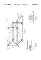
- FIG. 3is a schematic diagram shown in isometric view of a preferred embodiment of the screen and screen moving assembly of the display apparatus
- FIG. 4is an enlarged view of one of the pulleys of the screen moving assembly
- FIG. 5is an enlarged view of one of the bearings of the screen moving assembly
- FIG. 6is a schematic diagram shown in isometric view of an alternate embodiment of the screen and screen moving assembly of the display apparatus
- FIG. 7is a schematic diagram shown in isometric view of a further alternate embodiment of the screen and screen moving assembly of the display apparatus.
- FIG. 8is a schematic diagram in isometric view of an alternate embodiment of the screen.
- FIG. 9is a schematic and block diagram illustrating one embodiment of the control system of the imaging assembly.
- FIG. 10is a schematic and block diagram illustrating an alternate embodiment of the control system of the imaging assembly.
- the drawing figuresillustrate a three-dimensional display apparatus 10 constructed in accordance with the preferred embodiments of the present invention.
- the display apparatusgenerates and displays true three-dimensional images that can be viewed without the use of specially designed three-dimensional glasses.
- the display apparatusbroadly includes a screen 12, a screen moving assembly 14 for moving the screen to a plurality of different depth locations, and an imaging assembly generally referred to by the numeral 16 for generating and displaying images on the screen while the screen is moved between its different depth locations.
- the display apparatusgenerates and displays three-dimensional images by separating a signal representative of a three-dimensional image into its component two-dimensional images, successively generating the two-dimensional images with the imaging assembly, and projecting the two-dimensional images one at a time onto the screen as the screen is moved between its different depth locations.
- the screen 12is preferably a conventional cloth screen and may be formed in any desired size so that the display apparatus 10 may be used for any application including personal viewing and group viewing such as in a theater.
- the screenmay alternately be formed of a plane of liquid crystals that are switched to selectively turn the excitation voltage to the liquid crystals on or off. When the excitation voltage is turned off, the liquid crystals scatter light incident from one side of the screen so that the screen appears translucent.
- the top of the screen 12is attached to a rod 62 that extends across the width or y-axis of the viewing region.
- the bottom of the screenis attached to a rod 64 that extends across the width of the viewing region.
- the screen moving assembly 14which is best illustrated in FIG. 3, moves the screen 12 back and forth along the z-axis or depth space of a three-dimensional viewing region illustrated in FIG. 2.
- the z-axis of the viewing regionis divided into "Z1"-"Zp" depth locations.
- the screen moving assemblysuccessively moves the screen between each of these "Z1"-"Zp" depth locations.
- a depth space of approximately 300 mm (approximately 12") and a screen depth separation of approximately 0.5 mmare desirable for displaying realistic-looking three-dimensional images.
- the screen moving assemblypreferably moves the screen to approximately 600 different depth locations along the z-axis of the viewing region.
- the preferred screen moving assembly 14includes a motor 18 and a pulley system 20 rotatably coupled with the motor.
- the motorpreferably has a pair of rotating shafts 22.
- the pulley systemincludes four spaced pulleys 24,26,28,30 positioned at the four corners of the "Z1" depth location of the screen 12 and four spaced pulleys 32,34,36,38 positioned at the four comers of the "Zp" depth location of the screen.
- Each pulley 26-38is rotatably mounted to a support surface by a bearing assembly 40 as illustrated in FIG. 4.
- the pulley systemalso includes two additional pulleys 42,44 each attached to one of the rotating shafts 22 of the motor 18.
- the pulleys 24-38 and 40,42are interconnected by a plurality of belts 46,48,50,52,54,56,58,60 so that the pulleys jointly rotate with the shafts 22 of the motor 18.
- the screen 12is attached to the belts 46,48,50,52 so that it is moved back and forth along the z-axis of the viewing region as the pulleys are rotated by the motor.
- the ends of the screen rod 62are attached to bearings 66,68 that are coupled with belts 46,48.
- the ends of the screen rod 64are attached to bearings 70,72 that are coupled with belts 50,52.
- the outer surface of each bearing 66-72is fixed to its corresponding belt, and the inner surface of each bearing is connected to its corresponding rod.
- the screenmoves with the belts 46,48,50,52 between the depth locations "Z1"-"Zp" as the motor 18 rotates the pulleys 24-8.
- the screen moving assembly 14moves the screen 12 back and forth along the z-axis of the viewing region between the "Z1" location as depicted by the solid lines in FIG. 3 and the "Zp" location and several intermediate locations depicted by the dashed lines.
- the screen moving assembly 14moves the screen 12 back and forth along the depth of the viewing region without ever completely stopping the screen.
- vibration and noise associated with the movement of the screenis minimized.
- the bearings 40 and 66-72can be replaced by magnetic bearings or superconductive magnetic bearings. This construction is desirable where large projection screens are used such as in theaters.
- the entire display apparatus 10may be enclosed in a partially evacuated chamber to reduce the air friction or drag on the screen 12 while the screen is moved back and forth by the screen moving assembly 14.
- the screen alonemay be enclosed in an aerodynamically designed transparent container coated with anti-reflection material to further reduce the air resistance on the screen.
- the evacuated chamber and transparent containerreduce the amount of force that must be exerted on the screen to move it to various locations and therefore also reduce the noise and vibration of the display apparatus.
- the screen moving assembly 14also preferably includes an encoder 74 coupled with the motor 18 for sensing the exact rotational position of the shafts 22 and therefore the position of the screen 12.
- the encodergenerates a position signal that is sent to the imaging assembly 16 for synchronizing the operation of the imaging assembly with the positioning of the screen.
- FIG. 6illustrates an alternate embodiment of the screen moving assembly 14a that includes a motor 18a and a pulley system 20a rotatably coupled with the motor.
- the pulley systemincludes two spaced pulleys 22a,24a positioned on opposite sides of the "Z1" depth location of the screen 12, two spaced pulleys 26a,28apositioned on opposite sides of the "Zp" depth location of the screen, two spaced pulleys 30a, 32a coupled to the shafts of the motor, and four belts 34a,36a,38a,40a interconnecting the pulleys.
- the vertical side margins of the screenare rigidly connected to the belts 34a, 36a so that the screen is rotated 180° when it reaches both the "Z1" and "Zp" depth locations during its travel.
- FIG. 7illustrates another alternate embodiment of the screen moving assembly 14b that includes a motor 18b and a pulley system 20b rotatably coupled with the motor.
- the pulley systemincludes two spaced pulleys 22b,24b positioned on opposite sides of the "Z1" depth location of the screen 12, two spaced pulleys 26b,28b positioned on opposite sides of the "Zp" depth location of the screen, two spaced pulleys 30b,32b coupled to the shafts of the motor, and four belts 34b,36b,38b,40b interconnecting the pulleys.
- the pulley systemincludes two spaced pulleys 22b,24b positioned on opposite sides of the "Z1" depth location of the screen 12, two spaced pulleys 26b,28b positioned on opposite sides of the "Zp" depth location of the screen, two spaced pulleys 30b,32b coupled to the shafts of the motor, and four belts 34b,36b,38b,40b inter
- two screens 12are rigidly connected to the belts 34b,36b 180° out of phase from one another and both the screens are rotated 180° when they reach their "Z1" and "Zp" depth locations during their travel.
- the viewing area of the screenallows viewers to view only the screen that rides on the upper portion of the belts 34b,36b. This construction insures that only one screen is in view at a time.
- FIG. 8illustrates an alternate embodiment of the invention wherein the single screen 12 and screen moving assembly 14 are replaced with a plurality of fixed screens 76 each occupying one of the depth locations "Z1"-"Zp" along the z-axis of the viewing region.
- Each fixed screenis preferably formed from electro-optic or magneto-optic materials and can be switched between transparent and translucent states. Specifically, each screen is designed to pass light when a voltage is applied to the screen and to diffuse the incoming light when the voltage signal is removed from the screen. By forming the screens of electrooptic or magneto-optic materials, the amount of light diffusion by the screens can be controlled to make the screens useful as projection screens.
- the fixed screens 76 of this alternate embodimentare switched between their transparent and translucent states by a decoder 78.
- the decoderactivates each of the screens sequentially for a short time interval so that only one screen is translucent at any given moment. While a screen is translucent, the imaging assembly 16 generates and projects the appropriate two-dimensional image on the screen as described in more detail below.
- the imaging assembly 16which is best illustrated in FIG. 1, generates and projects a different two-dimensional image on the moveable screen 12 each time the screen is moved to one of its various depth locations "Z1"-"Zp" or each time a different one of the fixed screens 76 is made translucent.
- the preferred imaging assemblyincludes a CRT 80 for generating the two-dimensional images, a focusing system 82 for focusing the images from the CRT to the screen 12, and a control system 84 for controlling the operation of the CRT and synchronizing the generation of the two-dimensional images with the positioning of the screen.
- the CRTis conventional and includes a plurality of pixels.
- the CRTpreferably has a VGA format with 640 ⁇ 480 pixels.
- the focusing system 82projects and focuses the images created by the CRT 80 onto the screen 12 as the screen is moved between its various depth locations "Z1"-"Zp". Because the preferred display apparatus has a depth space of 12", the focusing system must focus the images generated by the CRT on the screen over a 12" depth space.
- the preferred focusing systemincludes a focusing lens 86 positioned in front of the CRT 80 and a focusing plate 88 having a small aperture 90 therein positioned between the lens and the screen 12.
- the size of the aperturedetermines the depth of focus of the lens. Specifically, as the aperture is made smaller, the depth of focus of the lens increases. However, as the aperture is made smaller, the amount of energy transferred to the screen by the lens is reduced, and therefore a more powerful CRT must be used. Applicant has discovered that an aperture having an f-stop in the range of 5.6-8.0 best balances the trade-off between the depth of focus of the lens and the energy transfer to the screen.
- the focusing lenscan be positioned to focus the images from the CRT to the front plane "Z1", when the aperture is fully open.
- electronic impulsesare used to reduce the size of the aperture as is done in most modern cameras.
- the size of the apertureis increased when the screen moves from "Zp" to "Z1". This configuration achieves higher power for the images formed at higher distances from the focusing lens, as compared to the fixed aperture configuration, at the expense of using an electronically controlled aperture.
- the focusing lens 86is moved back and forth by a stepper motor over a distance of a few millimeters. On moving the focusing lens over this small distance, the images created a by the CRT can be focused properly over the entire depth region of the display apparatus 10 without the use of a small apertured focusing plate 88. In this configuration, the power requirements of the CRT are reduced at the expense of the cost of the electromechanical lens movement system.
- the control system 84which is electrically coupled with the CRT 80, receives three-dimensional signals from the sources described above and drives the CRT in response thereto to generate and project the two-dimensional images on the screen 12 while the screen is moved between its various depth locations.
- the preferred control systemincludes a three-dimensional frame buffer processor 92, an active pixel processor 94, and a graphics driver 96.
- the frame buffer processor 92receives signals representative of three-dimensional images and separates the three-dimensional images into their component two-dimensional images. Specifically, the processor allocates every picture element in a three-dimensional image as a pixel of one of the "P" display planes and stores the information for all of the display planes in display-plane buffers 98. Thus, the processor creates a three-dimensional frame buffer that consists of "P" two-dimensional arrays stored in "P" display plane buffers.
- Table 2illustrates the content of the frame buffer for this three-dimensional image that shows the row number of a color table used to turn on every pixel of the 8 ⁇ 8 array.
- row 1, column 1 of the Tableindicates that the pixel 1,1 will be turned on with an intensity and color defined by the content of the row number 20 of a color table.
- the pixel 3,6will use the row number 81 of the color table.
- Each row of the color tableusually consists of three numbers defining the intensities of the red, green, and blue colors for the pixel. ##STR2##
- the frame buffer processor 92processes the contents of the above depth and frame buffers and produces 8 two-dimensional arrays corresponding to the eight depth planes of the three-dimensional image.
- the frame buffer processorthen stores these two-dimensional arrays in the display plane buffers 98.
- Tables 3 and 4 belowillustrate the contents of the first and eighth display plane buffers created by the frame buffer processor for this example. ##STR3##
- the graphics driver 96would access the contents of these display plane buffers 98 and then turn on the appropriate pixels of the CRT 80 in synchronization with the back and forth movement of the screen 12.
- the graphics driver of the CRTwould have to operate at a frequency of 600 ⁇ 640 ⁇ 480 ⁇ 30 (which equals approximately 5.4 Ghz) to generate acceptable three-dimensional images. This speed is more than 20 times greater than the speed of conventional graphics drivers used with the monitors for personal computers.
- the present inventionsolves this problem by recognizing that not all of the pixels of the CRT are active for each two-dimensional image of the overall three-dimensional image.
- Table 3illustrates that many of the pixels for the display-plane buffer No. 1 have a "0" color table value, which basically represents "0" intensity for the pixel. These pixels are not activated by the CRT and thus do not have to be accessed by the CRT.
- the active pixels processor 94takes advantage of this phenomenon by directing the CRT 80 to access only the active pixels for each two-dimensional image.
- the active pixels processordoes this by scanning every display-plane buffer 98 and generating a corresponding active pixels buffer 100 as illustrated in FIG. 9.
- Table 5illustrates the contents of the active pixels buffer for the display-plane buffer No. 8 set forth in Table 4. ##STR4##
- the first byte of each rowdefines the row number (r) of the pixel of the display-plane 8 that needs to be accessed.
- the content of the even numbered columnsdefine the column number (c) of the pixel that needs to be accessed.
- the row number of the color table that is used to access the pixelis defined by the content of the next higher odd numbered column.
- the first row of the active-pixels display-plane frame buffer number 8 aboveindicates that, for row 2 of the display-plane number 8, only the pixel at column 4 needs to be accessed. This accessing will be done by the content of the color table of row number 55.
- the row number 4 of the active-pixels display-plane frame buffer number 8defines that the pixel (6,4) will be accessed with a color table entry at row number 28 and the pixel (6,7) will be accessed with a color table entry at row number 78.
- a "0" value at any column other than the first column of a row of the active pixel buffer set forth in Table 5indicates to skip to the next row of the buffer.
- a value of "0" on the first column of a bufferindicates the end of accessing pixels of that plane.
- FIG. 10illustrates an alternate embodiment of the control system 84 in which a more powerful active pixels processor 94a directly creates the active-pixels buffers 100 by processing a three-dimensional signal without first separating the three-dimensional signal into its component two-dimensional images.
- This embodimentreduces the memory required since the two-dimensional images are not first stored in display-plane buffers 98; however, it requires a significantly more powerful active pixels processor.
- the graphics driver 96which is coupled between the active pixels buffers 100 and the CRT 80, scans the information in the buffers and activates only the active pixels of the CRT for each display plane. Such a scheme accesses only a limited number of pixels per plane, and therefore enables the display apparatus to access a larger number of projection planes with a traditional graphics driver. As discussed above, the graphics driver also receives a screen position signal from the encoder 74 and synchronizes the imaging assembly 16 with the movement of the screen.
- FIG. 2illustrates an exemplary three-dimensional viewing region created by the display apparatus.
- the x-y plane of the viewing regionrepresents the viewing plane of an observer, and the z-axis represents the depth of the viewing region.
- the viewing regionis divided into "P" discrete locations of equal size along its z-axis.
- the depth "dz" of each "P" regionis small enough so that the entire volume of the region can be considered as consisting of "P" two-dimensional viewing planes.
- the display apparatus 10moves the screen 12 back and forth in the viewing region along the z-axis to each of the "P" locations.
- the screenis initially moved from the "Z1" location to the "Zp” location and then back to the "Z1" location.
- the imaging assembly 16While the screen 12 is being moved, the imaging assembly 16 successively generates two-dimensional images on the CRT 80 as described above and projects and focuses these images on the screen in synchronization with the movement of the screen so that each two-dimensional image is projected to its proper depth location. For example, when the screen is moved to the position "Z1" illustrated in FIG. 2, the imaging assembly generates the two-dimensional image corresponding to this first plane of the three-dimensional image and projects this image onto the screen. Then, when the screen is moved to the position "Z2", the imaging assembly generates and projects the image corresponding to the second plane onto the screen. These procedures are repeated for every plane in the viewing region at a rate rapid enough to enable a viewer to visualize a three-dimensional display of the images.
- each plane of the liquid crystalscan be switched to behave as a translucent screen over a short time in an appropriate sequence so that the plane of projection actually moves from front to back repeatedly at a high speed.
- Flicker-free three-dimensional imagescan be visualized by accessing each projection plane at a rate greater than 30 times per second.
Landscapes
- Engineering & Computer Science (AREA)
- Multimedia (AREA)
- Signal Processing (AREA)
- Physics & Mathematics (AREA)
- General Physics & Mathematics (AREA)
- Optics & Photonics (AREA)
- Testing, Inspecting, Measuring Of Stereoscopic Televisions And Televisions (AREA)
Abstract
Description
Claims (22)
Priority Applications (3)
| Application Number | Priority Date | Filing Date | Title |
|---|---|---|---|
| US08/851,116US6005608A (en) | 1996-05-06 | 1997-05-05 | Three-dimensional display apparatus |
| PCT/US1997/007733WO1997042751A2 (en) | 1996-05-06 | 1997-05-06 | Three-dimensional display apparatus |
| AU29991/97AAU2999197A (en) | 1996-05-06 | 1997-05-06 | Three-dimensional display apparatus |
Applications Claiming Priority (2)
| Application Number | Priority Date | Filing Date | Title |
|---|---|---|---|
| US1696596P | 1996-05-06 | 1996-05-06 | |
| US08/851,116US6005608A (en) | 1996-05-06 | 1997-05-05 | Three-dimensional display apparatus |
Publications (1)
| Publication Number | Publication Date |
|---|---|
| US6005608Atrue US6005608A (en) | 1999-12-21 |
Family
ID=26689280
Family Applications (1)
| Application Number | Title | Priority Date | Filing Date |
|---|---|---|---|
| US08/851,116Expired - Fee RelatedUS6005608A (en) | 1996-05-06 | 1997-05-05 | Three-dimensional display apparatus |
Country Status (3)
| Country | Link |
|---|---|
| US (1) | US6005608A (en) |
| AU (1) | AU2999197A (en) |
| WO (1) | WO1997042751A2 (en) |
Cited By (14)
| Publication number | Priority date | Publication date | Assignee | Title |
|---|---|---|---|---|
| US6229562B1 (en)* | 1997-07-08 | 2001-05-08 | Stanley H. Kremen | System and apparatus for the recording and projection of images in substantially 3-dimensional format |
| US6646623B1 (en) | 1999-06-01 | 2003-11-11 | The University Of Kansas | Three-dimensional display apparatus |
| US20040150585A1 (en)* | 2003-01-24 | 2004-08-05 | Pioneer Corporation | Apparatus and method for displaying three-dimensional image |
| US20040150792A1 (en)* | 2003-01-24 | 2004-08-05 | Pioneer Corporation | Stereoscopic image display apparatus |
| US6798390B1 (en)* | 1997-08-29 | 2004-09-28 | Canon Kabushiki Kaisha | 3D image reconstructing apparatus and 3D object inputting apparatus |
| WO2004105403A1 (en) | 2003-05-23 | 2004-12-02 | Peter Boll | Method and device for three-dimensionally depicting images |
| US20050122479A1 (en)* | 2003-12-06 | 2005-06-09 | Mann Christopher W. | Three-dimensional display using optical fibers of different lengths |
| CN100366097C (en)* | 2005-07-13 | 2008-01-30 | 四川大学 | CRT projection true three-dimensional display system |
| US7602351B1 (en) | 2005-07-15 | 2009-10-13 | The United States Of America As Represented By The Secretary Of The Navy | Three-dimensional display assembly |
| US20090257243A1 (en)* | 2008-04-14 | 2009-10-15 | Dorian Christine Muench | Fiber optic display systems and related methods |
| US20110001746A1 (en)* | 2009-07-02 | 2011-01-06 | Samsung Electronics Co., Ltd. | Apparatuses for and methods of displaying three-dimensional images |
| US20130135321A1 (en)* | 2011-06-03 | 2013-05-30 | Immersion 3D Plus L.L.C. | Three-Dimensional Display Apparatus Electromechanical System |
| WO2013149614A1 (en) | 2012-04-04 | 2013-10-10 | Bernhard Wigger | Method for recording images |
| US10386711B2 (en)* | 2017-09-30 | 2019-08-20 | Shenzhen China Star Optoelectronics Semiconductor Display Technology Co., Ltd. | Displacement-type scanning stereoscopic display apparatus |
Families Citing this family (3)
| Publication number | Priority date | Publication date | Assignee | Title |
|---|---|---|---|---|
| DE10043272C2 (en)* | 2000-09-02 | 2002-08-01 | Alf Holger Tschersich | Device for generating three-dimensional images by means of a high-frequency moving, step-by-step field-emitting screen |
| CN103809367B (en)* | 2012-11-08 | 2016-08-17 | 耿征 | Real three-dimensional display system and true 3 D displaying method |
| WO2021228120A1 (en)* | 2020-05-13 | 2021-11-18 | 荆门市探梦科技有限公司 | Scanning-type holographic imaging device and related system |
Citations (26)
| Publication number | Priority date | Publication date | Assignee | Title |
|---|---|---|---|---|
| US2810318A (en)* | 1953-08-17 | 1957-10-22 | Wayne A Dockhorn | Stereoscopic apparatus |
| US3079959A (en)* | 1959-02-24 | 1963-03-05 | Arthur C Johnston | Three-d viewer |
| US3154636A (en)* | 1962-03-23 | 1964-10-27 | Xerox Corp | Three dimensional display device |
| US3555349A (en)* | 1968-07-17 | 1971-01-12 | Otto John Munz | Three-dimensional television system |
| US3891305A (en)* | 1973-05-08 | 1975-06-24 | Lester Fader | Apparatus for simulating a three-dimensional image by use of plural image producing surfaces |
| US3970361A (en)* | 1974-10-16 | 1976-07-20 | Dynell Electronics Corporation | Three-dimensional display system |
| US4472737A (en)* | 1982-08-31 | 1984-09-18 | Tokyo Shibaura Denki Kabushiki Kaisha | Stereographic tomogram observing apparatus |
| US4639081A (en)* | 1985-08-15 | 1987-01-27 | Kabushiki Kaisha Toshiba | Gimballed three-dimensional display system |
| US4670744A (en)* | 1985-03-14 | 1987-06-02 | Tektronix, Inc. | Light reflecting three-dimensional display system |
| US5003444A (en)* | 1988-08-02 | 1991-03-26 | Jan Secka | Means for all-around display of a flat image over an angle of 360 degrees |
| US5042909A (en)* | 1987-10-07 | 1991-08-27 | Texas Instruments Incorporated | Real time three dimensional display with angled rotating screen and method |
| US5057827A (en)* | 1988-10-17 | 1991-10-15 | Nobile Fred E | Means and method for producing an optical illusion |
| US5067167A (en)* | 1990-10-10 | 1991-11-19 | Cornell Research Foundation, Inc. | Apparatus and method for rotating of three-dimensional images |
| US5148310A (en)* | 1990-08-30 | 1992-09-15 | Batchko Robert G | Rotating flat screen fully addressable volume display system |
| US5161054A (en)* | 1990-12-19 | 1992-11-03 | Texas Instruments Incorporated | Projected volume display system and method |
| US5172266A (en)* | 1989-09-19 | 1992-12-15 | Texas Instruments Incorporated | Real time three dimensional display |
| US5257086A (en)* | 1992-06-09 | 1993-10-26 | D.O.M. Associates Int'l | Optical spectrophotometer having a multi-element light source |
| US5455196A (en)* | 1991-12-31 | 1995-10-03 | Texas Instruments Incorporated | Method of forming an array of electron emitters |
| US5479185A (en)* | 1992-12-09 | 1995-12-26 | Celsius Tech Electronics Ab | Display arrangement |
| US5592215A (en)* | 1993-02-03 | 1997-01-07 | Rohm Co., Ltd. | Stereoscopic picture system and stereoscopic display panel therefor |
| US5627554A (en)* | 1995-04-18 | 1997-05-06 | Jefferson; Gordon V. | Segmented direct volume display device and method |
| US5650813A (en)* | 1992-11-20 | 1997-07-22 | Picker International, Inc. | Panoramic time delay and integration video camera system |
| US5703606A (en)* | 1992-09-10 | 1997-12-30 | Blundell; Barry George | Three dimensional display system |
| US5754147A (en)* | 1993-08-18 | 1998-05-19 | Tsao; Che-Chih | Method and apparatus for displaying three-dimensional volumetric images |
| US5801666A (en)* | 1993-02-10 | 1998-09-01 | Board Of Regents, The University Of Texas System | Three-dimensional monitor |
| US5867152A (en)* | 1994-03-22 | 1999-02-02 | Raytheon Ti Systems, Inc. | On-line laser alignment system for three dimensional display |
Family Cites Families (4)
| Publication number | Priority date | Publication date | Assignee | Title |
|---|---|---|---|---|
| US4160973A (en)* | 1977-10-11 | 1979-07-10 | Massachusetts Institute Of Technology | Three-dimensional display |
| SE444092B (en)* | 1985-04-29 | 1986-03-17 | Prismavision Ab | DRIVING DEVICE ON SIGNS WITH LOVELY SCREENS |
| US4757379A (en)* | 1986-04-14 | 1988-07-12 | Contour Dynamics | Apparatus and method for acquisition of 3D images |
| US5082350A (en)* | 1987-10-07 | 1992-01-21 | Texas Instruments Incorporated | Real time three dimensional display system for displaying images in three dimensions which are projected onto a screen in two dimensions |
- 1997
- 1997-05-05USUS08/851,116patent/US6005608A/ennot_activeExpired - Fee Related
- 1997-05-06WOPCT/US1997/007733patent/WO1997042751A2/enactiveApplication Filing
- 1997-05-06AUAU29991/97Apatent/AU2999197A/ennot_activeAbandoned
Patent Citations (26)
| Publication number | Priority date | Publication date | Assignee | Title |
|---|---|---|---|---|
| US2810318A (en)* | 1953-08-17 | 1957-10-22 | Wayne A Dockhorn | Stereoscopic apparatus |
| US3079959A (en)* | 1959-02-24 | 1963-03-05 | Arthur C Johnston | Three-d viewer |
| US3154636A (en)* | 1962-03-23 | 1964-10-27 | Xerox Corp | Three dimensional display device |
| US3555349A (en)* | 1968-07-17 | 1971-01-12 | Otto John Munz | Three-dimensional television system |
| US3891305A (en)* | 1973-05-08 | 1975-06-24 | Lester Fader | Apparatus for simulating a three-dimensional image by use of plural image producing surfaces |
| US3970361A (en)* | 1974-10-16 | 1976-07-20 | Dynell Electronics Corporation | Three-dimensional display system |
| US4472737A (en)* | 1982-08-31 | 1984-09-18 | Tokyo Shibaura Denki Kabushiki Kaisha | Stereographic tomogram observing apparatus |
| US4670744A (en)* | 1985-03-14 | 1987-06-02 | Tektronix, Inc. | Light reflecting three-dimensional display system |
| US4639081A (en)* | 1985-08-15 | 1987-01-27 | Kabushiki Kaisha Toshiba | Gimballed three-dimensional display system |
| US5042909A (en)* | 1987-10-07 | 1991-08-27 | Texas Instruments Incorporated | Real time three dimensional display with angled rotating screen and method |
| US5003444A (en)* | 1988-08-02 | 1991-03-26 | Jan Secka | Means for all-around display of a flat image over an angle of 360 degrees |
| US5057827A (en)* | 1988-10-17 | 1991-10-15 | Nobile Fred E | Means and method for producing an optical illusion |
| US5172266A (en)* | 1989-09-19 | 1992-12-15 | Texas Instruments Incorporated | Real time three dimensional display |
| US5148310A (en)* | 1990-08-30 | 1992-09-15 | Batchko Robert G | Rotating flat screen fully addressable volume display system |
| US5067167A (en)* | 1990-10-10 | 1991-11-19 | Cornell Research Foundation, Inc. | Apparatus and method for rotating of three-dimensional images |
| US5161054A (en)* | 1990-12-19 | 1992-11-03 | Texas Instruments Incorporated | Projected volume display system and method |
| US5455196A (en)* | 1991-12-31 | 1995-10-03 | Texas Instruments Incorporated | Method of forming an array of electron emitters |
| US5257086A (en)* | 1992-06-09 | 1993-10-26 | D.O.M. Associates Int'l | Optical spectrophotometer having a multi-element light source |
| US5703606A (en)* | 1992-09-10 | 1997-12-30 | Blundell; Barry George | Three dimensional display system |
| US5650813A (en)* | 1992-11-20 | 1997-07-22 | Picker International, Inc. | Panoramic time delay and integration video camera system |
| US5479185A (en)* | 1992-12-09 | 1995-12-26 | Celsius Tech Electronics Ab | Display arrangement |
| US5592215A (en)* | 1993-02-03 | 1997-01-07 | Rohm Co., Ltd. | Stereoscopic picture system and stereoscopic display panel therefor |
| US5801666A (en)* | 1993-02-10 | 1998-09-01 | Board Of Regents, The University Of Texas System | Three-dimensional monitor |
| US5754147A (en)* | 1993-08-18 | 1998-05-19 | Tsao; Che-Chih | Method and apparatus for displaying three-dimensional volumetric images |
| US5867152A (en)* | 1994-03-22 | 1999-02-02 | Raytheon Ti Systems, Inc. | On-line laser alignment system for three dimensional display |
| US5627554A (en)* | 1995-04-18 | 1997-05-06 | Jefferson; Gordon V. | Segmented direct volume display device and method |
Cited By (22)
| Publication number | Priority date | Publication date | Assignee | Title |
|---|---|---|---|---|
| US7142232B2 (en) | 1997-07-08 | 2006-11-28 | Kremen Stanley H | System and apparatus for recording and projecting 3-dimensional images |
| US6229562B1 (en)* | 1997-07-08 | 2001-05-08 | Stanley H. Kremen | System and apparatus for the recording and projection of images in substantially 3-dimensional format |
| US6798390B1 (en)* | 1997-08-29 | 2004-09-28 | Canon Kabushiki Kaisha | 3D image reconstructing apparatus and 3D object inputting apparatus |
| US6646623B1 (en) | 1999-06-01 | 2003-11-11 | The University Of Kansas | Three-dimensional display apparatus |
| US20040150585A1 (en)* | 2003-01-24 | 2004-08-05 | Pioneer Corporation | Apparatus and method for displaying three-dimensional image |
| US20040150792A1 (en)* | 2003-01-24 | 2004-08-05 | Pioneer Corporation | Stereoscopic image display apparatus |
| US7319436B2 (en)* | 2003-01-24 | 2008-01-15 | Pioneer Corporation | Apparatus and method for displaying three-dimensional image |
| US7165841B2 (en)* | 2003-01-24 | 2007-01-23 | Pioneer Corporation | Stereoscopic image display apparatus |
| US20070070062A1 (en)* | 2003-05-23 | 2007-03-29 | Peter Boll | Method and apparatus for three-dimensional display of images |
| US9041624B2 (en) | 2003-05-23 | 2015-05-26 | Peter Boll | Method and apparatus for three-dimensional display of images |
| WO2004105403A1 (en) | 2003-05-23 | 2004-12-02 | Peter Boll | Method and device for three-dimensionally depicting images |
| US20050122479A1 (en)* | 2003-12-06 | 2005-06-09 | Mann Christopher W. | Three-dimensional display using optical fibers of different lengths |
| US6948819B2 (en)* | 2003-12-06 | 2005-09-27 | Christopher Westlye Mann | Three-dimensional display using optical fibers of different lengths |
| CN100366097C (en)* | 2005-07-13 | 2008-01-30 | 四川大学 | CRT projection true three-dimensional display system |
| US7602351B1 (en) | 2005-07-15 | 2009-10-13 | The United States Of America As Represented By The Secretary Of The Navy | Three-dimensional display assembly |
| US20090257243A1 (en)* | 2008-04-14 | 2009-10-15 | Dorian Christine Muench | Fiber optic display systems and related methods |
| US7985016B2 (en) | 2008-04-14 | 2011-07-26 | Dorian Christine Webb Fritze | Fiber optic display systems and related methods |
| US20110001746A1 (en)* | 2009-07-02 | 2011-01-06 | Samsung Electronics Co., Ltd. | Apparatuses for and methods of displaying three-dimensional images |
| US8633868B2 (en)* | 2009-07-02 | 2014-01-21 | Samsung Electronics Co., Ltd. | Apparatuses for and methods of displaying three-dimensional images |
| US20130135321A1 (en)* | 2011-06-03 | 2013-05-30 | Immersion 3D Plus L.L.C. | Three-Dimensional Display Apparatus Electromechanical System |
| WO2013149614A1 (en) | 2012-04-04 | 2013-10-10 | Bernhard Wigger | Method for recording images |
| US10386711B2 (en)* | 2017-09-30 | 2019-08-20 | Shenzhen China Star Optoelectronics Semiconductor Display Technology Co., Ltd. | Displacement-type scanning stereoscopic display apparatus |
Also Published As
| Publication number | Publication date |
|---|---|
| AU2999197A (en) | 1997-11-26 |
| WO1997042751A3 (en) | 1997-12-11 |
| WO1997042751A2 (en) | 1997-11-13 |
Similar Documents
| Publication | Publication Date | Title |
|---|---|---|
| US6005608A (en) | Three-dimensional display apparatus | |
| EP0391529B1 (en) | Apparatus for digitized video system | |
| US5192946A (en) | Digitized color video display system | |
| US5206629A (en) | Spatial light modulator and memory for digitized video display | |
| US5162787A (en) | Apparatus and method for digitized video system utilizing a moving display surface | |
| US6049317A (en) | System for imaging of light-sensitive media | |
| US5170156A (en) | Multi-frequency two dimensional display system | |
| US5214420A (en) | Spatial light modulator projection system with random polarity light | |
| US5079544A (en) | Standard independent digitized video system | |
| US5287096A (en) | Variable luminosity display system | |
| US5589852A (en) | Apparatus and method for image projection with pixel intensity control | |
| US5128660A (en) | Pointer for three dimensional display | |
| EP0571363B1 (en) | Solid state 360 degree viewing apparatus | |
| US4922336A (en) | Three dimensional display system | |
| US5519533A (en) | Three-dimensional information reproducing apparatus | |
| US5416509A (en) | Method and apparatus for the generation of a stereoscopic presentation | |
| US4290083A (en) | Stereoscopic television (unaided) on standard bandwidth-method and apparatus | |
| EP0385705B1 (en) | Apparatus and method for digitized 3D video system | |
| Eichenlaub | Developments in autosterioscopic technology at Dimension Technologies Inc. | |
| US4979026A (en) | Polarized light 360 degree viewing system | |
| US11295642B2 (en) | Three-dimensional image display system | |
| EP0385706B1 (en) | Apparatus and method for digitized video system | |
| Eichenlaub | Progress in autostereoscopic display technology at Dimension Technologies Inc. | |
| KR100658669B1 (en) | Stereoscopic image display system | |
| GB2095068A (en) | Stereoscopic television |
Legal Events
| Date | Code | Title | Description |
|---|---|---|---|
| AS | Assignment | Owner name:UNIVERSITY OF KANSAS, THE, KANSAS Free format text:ASSIGNMENT OF ASSIGNORS INTEREST;ASSIGNOR:CHAKRABARTI, SWAPAN;REEL/FRAME:008659/0006 Effective date:19970502 | |
| FEPP | Fee payment procedure | Free format text:PAT HOLDER CLAIMS SMALL ENTITY STATUS, ENTITY STATUS SET TO SMALL (ORIGINAL EVENT CODE: LTOS); ENTITY STATUS OF PATENT OWNER: SMALL ENTITY | |
| FPAY | Fee payment | Year of fee payment:4 | |
| REMI | Maintenance fee reminder mailed | ||
| FEPP | Fee payment procedure | Free format text:PAYOR NUMBER ASSIGNED (ORIGINAL EVENT CODE: ASPN); ENTITY STATUS OF PATENT OWNER: SMALL ENTITY | |
| LAPS | Lapse for failure to pay maintenance fees | ||
| STCH | Information on status: patent discontinuation | Free format text:PATENT EXPIRED DUE TO NONPAYMENT OF MAINTENANCE FEES UNDER 37 CFR 1.362 | |
| FP | Lapsed due to failure to pay maintenance fee | Effective date:20071221 | |
| AS | Assignment | Owner name:CHAKRABARTI, SWAPAN, KANSAS Free format text:ASSIGNMENT OF ASSIGNORS INTEREST;ASSIGNOR:KANSAS, UNIVERSITY OF;REEL/FRAME:034894/0482 Effective date:20140919 | |
| AS | Assignment | Owner name:IMMERSION 3D PLUS L.L.C., KANSAS Free format text:ASSIGNMENT OF ASSIGNORS INTEREST;ASSIGNOR:CHAKRABARTI, SWAPAN;REEL/FRAME:034996/0905 Effective date:20150220 |