US6004312A - Computerized EMG diagnostic system - Google Patents
Computerized EMG diagnostic systemDownload PDFInfo
- Publication number
- US6004312A US6004312AUS09/032,730US3273098AUS6004312AUS 6004312 AUS6004312 AUS 6004312AUS 3273098 AUS3273098 AUS 3273098AUS 6004312 AUS6004312 AUS 6004312A
- Authority
- US
- United States
- Prior art keywords
- signals
- electrodes
- array
- visual
- patient
- Prior art date
- Legal status (The legal status is an assumption and is not a legal conclusion. Google has not performed a legal analysis and makes no representation as to the accuracy of the status listed.)
- Expired - Lifetime
Links
- 210000003205muscleAnatomy0.000claimsabstractdescription77
- 230000000694effectsEffects0.000claimsabstractdescription58
- 230000000007visual effectEffects0.000claimsdescription90
- 238000000034methodMethods0.000claimsdescription39
- 210000003484anatomyAnatomy0.000claimsdescription38
- 238000012545processingMethods0.000claimsdescription29
- 238000004458analytical methodMethods0.000claimsdescription19
- 230000003750conditioning effectEffects0.000claimsdescription17
- 230000000875corresponding effectEffects0.000claimsdescription15
- 238000012544monitoring processMethods0.000claimsdescription15
- 230000001143conditioned effectEffects0.000claimsdescription9
- 230000002596correlated effectEffects0.000claimsdescription8
- 239000011159matrix materialSubstances0.000claimsdescription6
- 230000008859changeEffects0.000claimsdescription4
- 230000001419dependent effectEffects0.000claims2
- 241000282414Homo sapiensSpecies0.000abstractdescription16
- 230000000717retained effectEffects0.000abstractdescription6
- 238000011156evaluationMethods0.000description8
- 230000002159abnormal effectEffects0.000description6
- 238000010586diagramMethods0.000description6
- 230000033001locomotionEffects0.000description6
- 239000003086colorantSubstances0.000description4
- 230000008602contractionEffects0.000description4
- 238000011161developmentMethods0.000description4
- 230000018109developmental processEffects0.000description4
- 238000003745diagnosisMethods0.000description3
- 238000004070electrodepositionMethods0.000description3
- 238000005516engineering processMethods0.000description3
- 238000001914filtrationMethods0.000description3
- 230000003387muscularEffects0.000description3
- 210000000115thoracic cavityAnatomy0.000description3
- 208000008930Low Back PainDiseases0.000description2
- 230000008901benefitEffects0.000description2
- 230000005540biological transmissionEffects0.000description2
- 238000004364calculation methodMethods0.000description2
- 239000004020conductorSubstances0.000description2
- 238000002565electrocardiographyMethods0.000description2
- 210000003414extremityAnatomy0.000description2
- 238000005259measurementMethods0.000description2
- 238000012986modificationMethods0.000description2
- 230000004048modificationEffects0.000description2
- 210000005036nerveAnatomy0.000description2
- 230000010355oscillationEffects0.000description2
- 230000008569processEffects0.000description2
- 238000012360testing methodMethods0.000description2
- 238000012935AveragingMethods0.000description1
- 208000008035Back PainDiseases0.000description1
- RYGMFSIKBFXOCR-UHFFFAOYSA-NCopperChemical compound[Cu]RYGMFSIKBFXOCR-UHFFFAOYSA-N0.000description1
- 241000282412HomoSpecies0.000description1
- 239000004677NylonSubstances0.000description1
- 239000004820Pressure-sensitive adhesiveSubstances0.000description1
- 230000005856abnormalityEffects0.000description1
- 230000006978adaptationEffects0.000description1
- 239000000853adhesiveSubstances0.000description1
- 230000001070adhesive effectEffects0.000description1
- 230000003321amplificationEffects0.000description1
- 238000003491arrayMethods0.000description1
- 230000002457bidirectional effectEffects0.000description1
- 230000003139buffering effectEffects0.000description1
- 238000006243chemical reactionMethods0.000description1
- 150000001875compoundsChemical class0.000description1
- 230000002950deficientEffects0.000description1
- 238000001514detection methodMethods0.000description1
- 230000004064dysfunctionEffects0.000description1
- 230000003670easy-to-cleanEffects0.000description1
- 238000002567electromyographyMethods0.000description1
- 230000002708enhancing effectEffects0.000description1
- 238000012854evaluation processMethods0.000description1
- 239000004744fabricSubstances0.000description1
- 239000000835fiberSubstances0.000description1
- 239000006260foamSubstances0.000description1
- 230000036039immunityEffects0.000description1
- 230000006872improvementEffects0.000description1
- 238000011835investigationMethods0.000description1
- 238000002955isolationMethods0.000description1
- 239000003550markerSubstances0.000description1
- 239000000463materialSubstances0.000description1
- 230000007246mechanismEffects0.000description1
- 239000003607modifierSubstances0.000description1
- 239000013518molded foamSubstances0.000description1
- 230000004220muscle functionEffects0.000description1
- 230000007935neutral effectEffects0.000description1
- 238000003199nucleic acid amplification methodMethods0.000description1
- 229920001778nylonPolymers0.000description1
- 238000002559palpationMethods0.000description1
- 238000012552reviewMethods0.000description1
- 210000001991scapulaAnatomy0.000description1
- 230000035945sensitivityEffects0.000description1
- 230000003595spectral effectEffects0.000description1
- 229910001220stainless steelInorganic materials0.000description1
- 239000010935stainless steelSubstances0.000description1
- 238000006467substitution reactionMethods0.000description1
- 208000011580syndromic diseaseDiseases0.000description1
- 238000012800visualizationMethods0.000description1
- 239000004520water soluble gelSubstances0.000description1
- 210000000707wristAnatomy0.000description1
Images


Classifications
- A—HUMAN NECESSITIES
- A61—MEDICAL OR VETERINARY SCIENCE; HYGIENE
- A61B—DIAGNOSIS; SURGERY; IDENTIFICATION
- A61B5/00—Measuring for diagnostic purposes; Identification of persons
- A61B5/24—Detecting, measuring or recording bioelectric or biomagnetic signals of the body or parts thereof
- A61B5/30—Input circuits therefor
- A—HUMAN NECESSITIES
- A61—MEDICAL OR VETERINARY SCIENCE; HYGIENE
- A61B—DIAGNOSIS; SURGERY; IDENTIFICATION
- A61B5/00—Measuring for diagnostic purposes; Identification of persons
- A61B5/24—Detecting, measuring or recording bioelectric or biomagnetic signals of the body or parts thereof
- A61B5/25—Bioelectric electrodes therefor
- A61B5/279—Bioelectric electrodes therefor specially adapted for particular uses
- A61B5/28—Bioelectric electrodes therefor specially adapted for particular uses for electrocardiography [ECG]
- A61B5/282—Holders for multiple electrodes
- A—HUMAN NECESSITIES
- A61—MEDICAL OR VETERINARY SCIENCE; HYGIENE
- A61B—DIAGNOSIS; SURGERY; IDENTIFICATION
- A61B5/00—Measuring for diagnostic purposes; Identification of persons
- A61B5/24—Detecting, measuring or recording bioelectric or biomagnetic signals of the body or parts thereof
- A61B5/25—Bioelectric electrodes therefor
- A61B5/279—Bioelectric electrodes therefor specially adapted for particular uses
- A61B5/296—Bioelectric electrodes therefor specially adapted for particular uses for electromyography [EMG]
Definitions
- This inventionrelates to a method and apparatus for monitoring and displaying the condition of muscles in a muscle group by the sensing and analysis of electromyographic signals derived from a non-invasive body surface electrode array positioned close to the muscle group.
- PrutchiTypical of this prior art is the device described by D. Prutchi in the publication "A High-Resolution Large Array (HRLA) EMG System", published September 1995 in Med. Eng. Phys., Vol. 17, 442-454. Prutchi describes a bracelet which may be wrapped about a body limb and which contains 256 surface electrodes to record the electrical activity of underlying muscles. The electrodes are arranged in eight groups of thirty-two electrode linear arrays directly connected to buffer boards in close proximity of the electrodes.
- HRLAHigh-Resolution Large Array
- U.S. Pat. No. 5,086,779 to DeLuca, et al.describes a back analysis system of plural electrodes coupled to a computer system for processing the signals and to provide graphical representations of results.
- DeLuca's inventionrelates primarily to isolating particular muscle groups by the use of support and restraint devices which limit the movement of the patient's torso in predetermined patterns correlated to the desired muscle groups.
- DeLuca's electrode arrayconsists of separate electrodes individually placed at desired locations on a patient's back.
- U.S. Pat. No. 5,058,602 to Brodydescribes a method of electromyographic scanning of paravertebral muscles comprising measuring electrical potentials bilaterally across segments of the spine. Readings are categorized into different patterns which are indicative of different muscular conditions. Brody suggests equipment useful within his described techniques as an available EMG scanner having electrodes spaced 2.5 cm apart and a computer component, but provides few details on the equipment or an indication of usefulness for isolating certain muscles or muscle groups.
- Kadefors' electrode systemcomprises three electrodes, one of which is a reference marker.
- This electronic apparatusin essence, includes a sample and hold function in which current responses can be compared to earlier responses and an indication provided based on the differences detected.
- U.S. Pat. No. 5,505,208 to Toormin, et al.describes a method for determining the status of back muscles wherein EMG signals are monitored from a number of electrodes placed in a pattern on a patient's back, the activity of each electrode is determined and the results stored.
- a database of resultsprovides a standard from which comparisons can be made to determine deviations or abnormalities, as a device for the care and management of the patient's dysfunction.
- U.S. Pat. No. 5,513,651 to Cusimano, et al.describes a portable electronic instrument for monitoring muscle activity, using standard ECG electrodes and a computer for analyzing the detected signals.
- the electrodesare applied individually at predetermined locations and a range of motion device is employed to generate signals related to a particular muscle group.
- Output plotsare produced to provide an indication of results, apparently in the form of printouts of information reflecting any deviations from the norm of expected muscle activity.
- An object of the present inventionis to provide improved surface EMG equipment, readily useable by the skilled examining physician, for the diagnosis or treatment monitoring of patients with low back pain.
- a further object of the present inventionis to provide an improved clinical tool which is portable and which uses non-invasive techniques for the collection of signals.
- a further object of the present inventionis to provide improved EMG equipment which to provides a visual display of the activity of muscles or muscle groups.
- a further object of the present inventionis to provide improved EMG equipment in which the visual display of muscle activity is juxtaposed over a visual display of normal muscle anatomy for correlation by the examining physician.
- a further object of the present inventionis to provide improved EMG equipment in which the visual display can be selected for specific musculature identified by the examining physician.
- a further object of the present inventionis to provide improved EMG equipment which utilizes a single detector pad of electrodes in which the electrodes are arranged in a specific array, to monitor instantaneously all specific muscles in a muscle group of a patient.
- the electromyographic (EMG) diagnostic system of the present inventionis particularly suited for evaluation of the lower back of a human and consists essentially of a sensor pad for collecting and conditioning EMG signals, electronic equipment including a computer for signal discrimination and evaluation and a display device for providing a visual display of the activity of selected musculature.
- a ground electrodeis positioned on the patient.
- the electronic equipmentserves to receive signals from the sensor pad which is pressed against the lower back of a patient in a predetermined location and held immobile relative to the patient such as by strap with foam backing, an inflatable bladder, an adhesive pad or other convenient arrangement. Signals from individual electrodes are conditioned by the electrical equipment, discriminated from noise signals and the like and evaluated relative to the signal received from the reference electrode.
- Computer apparatusis then used to analyze the signals, and can combine the signals in various patterns to provide an analysis of the muscular anatomy of the lower back and the activity of such muscles.
- a preferred technique for signal monitoringis to determine the RMS voltage of the sensed signals over a predetermined time interval.
- the RMS voltageis converted to a visual display representative of the power level, which display then provides a visual indication of those locations where a higher level of muscle activity is detected.
- the RMS signal techniqueis advantageous in providing a device for averaging the highly sensitive and often variable individual electrode signals which are susceptible to changes in contact resistance at the electrode, the human skin resistance, stray field fluctuation, inadvertent movements by the patient, and the like, which can introduce false signals, and mask the desired muscle activity signals.
- a visual display of the sensed muscle activityis provided on a monitor, such as a cathode ray tube type monitor, which may then be evaluated by the attending physician.
- a predetermined display of normal back anatomyis displayed simultaneously on the monitor to assist the physician in his evaluation. For example colorization of the resultant sensed display with different colors representing the degree of contraction thus provides a vivid indication of abnormal activity of the muscle.
- Normal back anatomyis provided in this invention by the selection from an inventory of various back muscle configurations which depict different layers of back muscles of the normal human patient. These configurations are selectable by the physician for comparison with the sensed muscle activity pattern in order to assist in providing a correlation between the two.
- Further controlis provided in that the physician not only can alter the physical configuration of the sensed signal display but also can adjust the intensity or colorization of the sensed display to render a more pronounced image of abnormal muscle activity relative to normal back anatomy.
- Visual display modificationis achieved by adjustment of the sensitivity of the sensed signal detector or by increasing the level of signal over which a visual indication is provided.
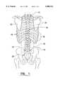
- FIG. 1is a simplified schematic overview of a portion of the lower back skeletal structure of a patient with an outline of the sensor pad portion of the invention depicted in position thereover.
- FIG. 2is a schematic view of the apparatus of the invention, comprising the sensor pad in connection with electronic apparatus including a computer and display unit.
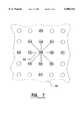
- FIG. 3is a schematic view of the screen of the display unit of the invention showing a full color bar matrix overlay in relation to the lower back skeletal anatomy of a human patient.
- FIG. 4is a view partly in cross-section of a portion of the sensor pad of the invention, showing a single electrode and the electrical connection to the computer portion of the invention.
- FIG. 5is an enlarged plan view only of the single electrode shown in FIG. 4.
- FIG. 6is a cross-sectional view of a single electrode taken along the lines 6--6 of FIG. 5.
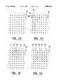
- FIG. 7is a schematic view of the screen of the display unit of the invention depicting the location of a portion of the electrodes of the sensor pad as circles and showing several interconnecting color bars.
- FIG. 8is a schematic view of the lower torso of a patient with the sensor pad held in position by a retaining belt and a support pad.
- FIG. 9is a plan view with parts removed of the retaining belt of FIG. 8, showing the support pad.
- FIGS. 10-13are schematic views of the screen of the display unit showing various configurations of color bar displays.
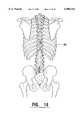
- FIG. 14is a schematic diagram of skeletal anatomy associated with the lower back of a normal human patient.
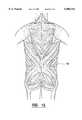
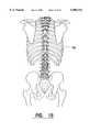
- FIGS. 15-23are schematic diagrams of various groups of musculature of a normal human patient shown in relation to the skeletal anatomy of FIG. 14.
- FIG. 24is a schematic view of the apparatus of the invention, similar to that of FIGS. 2 and 4, in a modified showing of the interrelation of components of the invention.
- FIG. 25is a schematic view of the components comprising the Analog Signal Conditioning Subsystem of FIG. 24.
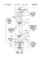
- FIG. 26is a schematic view of the components comprising the Signal Processing Subsystem of FIG. 24.
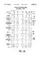
- FIG. 27is a logic diagram showing the data flow in the software of the system.
- FIG. 28is a chart of a portion of the software program of the invention, showing a header format.
- FIG. 29is a chart of a portion of the software program of the invention, showing a listing of files developed therein.
- FIG. 30is a chart of a portion of the software program of the invention, showing generally the Source File Structure.
- sensor pad 10is a device for collecting electromyographic (EMG) signals from the underlying muscle structure supporting and providing movement to the spine 11.
- EMGelectromyographic
- the muscle structureis a complicated array of muscles consisting of at least sixty-nine erector and intrinsic muscles in the thoracolumbosacral spine extending from about the tenth thoracic vertebrae 18 to the sacrum 20.
- EMG signals and their relation to muscle functionsare well understood at the current state of investigations.
- Musclesare controlled by nerves, the latter transmitting an electrical signal to a particular muscle and causing contraction thereof.
- the muscle itselfis a volume conductor reacting to the signal of the associated nerve.
- sensor pad 10is a flat rectangular piece of siliconized rubber, approximately 0.062 inch thick, measuring about 12 ⁇ 12 inches and with a Durometer hardness on the order of 20 to 40.
- One source for sensor pad 10is Fairprene Industrial Products, Inc. of Fairfield, Conn.
- Sensor pad 10further comprises an array of sixty-three electrodes 28, preferably made of 316 L stainless steel. Electrodes 28 are arranged in a 7 ⁇ 9 pattern, with the electrodes in each row and column being spaced 1.162 inches apart on center. A central column 29 of nine electrodes 28 is located in the middle of sensor pad 10 to overlay the spine 11 of the patient, and three equally spaced parallel columns of nine electrodes each are positioned on either side of the central column 29. Similarly, a central row 30 of seven electrodes 28 is positioned near the center of sensor pad 10, and four parallel rows of seven electrodes each are positioned on either side of central row 30. Ground electrode 31, is a standard electrode preferably positioned on a wrist of the patient.
- All of the electrodes 28,are identical and one configuration is shown in greater detail in FIGS. 4-6 as comprising a pyramidal tipped, bolt-shaped structure having a head 32 and integral threaded shaft 34.
- Head 32is circular and includes a plurality of pyramids 35 distributed substantially evenly and projecting outwardly of the upper surface of head 32 to form the patient-contacting surface of electrode 28.
- Head 32is preferably 0.375 inches in diameter and has a thickness of 0.08 inches from the lower surface thereof at the junction with shaft 34, to the tips 36 of pyramids 35.
- Pyramids 35are formed by grinding electrode head 32 in a series of parallel and orthogonal passes or by electromachining to produce a square pyramidal shape having an altitude of 0.042 inches, an angle of 90 degrees between opposing pyramid faces and culminating in a tip 36 having a radius of 0.005 inch. Tips 36 are spaced 0.094 inches from one another and in this embodiment of the invention, result in an electrode 28 having twelve pyramids 35 and tips 36 at the signal-collecting surface thereof. It has been determined that this configuration of electrode 28 is particularly useful in enhancing lower contact resistance when placed in position on a patient, thereby assuring better EMG signal reception and greater accuracy of the measurement.
- Each electrode 28is mounted in an aperture in sensor pad 10 and retained in position by a nut 170 threaded to shaft 34.
- electrode 28may have an unthreaded shaft 34 and be retained in position by a push connector.
- a solderless ring connector 38is also received on shaft 34 and is firmly secured by outer nut 39 to provide an electrical interconnection with the signal gathering surface of electrode 28.
- An electrode wire 40is crimped to connector 38 and each of the electrode wires 40 is routed over the surface of sensor pad 10 to a pigtail at the upper end of sensor pad 10 which terminates at a connector 41.
- Each electrode wire 40is preferably a 30 gauge, multi strand, flexible copper wire which allows for some deformation of sensor pad 10 to conform to the lower back of a patient, while connector 41 allows for releasable connection of the sensor pad to the electrical circuitry to facilitate substitution of components of the apparatus of the invention.
- the edge to edge spacing of electrodes 28 in each column 29 and row 30is 2.0 centimeters or approximately 0.79 inches. This has been determined to provide enough distance between electrodes 28 to result in a meaningful signal difference between electrodes.
- the electronic circuitry comprising preamplifier 23is located near sensor pad 10 for conditioning and amplifying the signals received at electrodes 28.
- Electrode wire 40is connected to buffer amplifier 42, and the signal in turn is routed to low pass filter 43 and high pass filter 44 for each electrode 28 of sensor pad 10. Conditioning of the signals preferably occurs closely adjacent the patient and avoids remote transmission of very low level signals in a background of randomly generated noise signals.
- Buffer amplifier 42minimizes leakage current through the electrode and errors due to electrode impedance changes.
- High pass filter 44serves as an anti-aliasing filter, and low pass filter 43 prevents saturation of analog to digital (A/D) converter 24 by offset voltages, such filters being well understood in the art.
- preamplifier 23includes Buffer/Amplifier module 42 and Filter/Buffer module 105.
- Cable 45connects the components of preamplifier 23 to analog to digital (A/D) converter 24 for transmission of the electrode signals for further processing and analysis.
- A/Danalog to digital
- Sensor pad 10is applied to the back of a patient by orienting certain of the electrodes 28 to the skeletal structure of the patient.
- the central electrode in the top row of electrode rows 30, i.e., electrode 46is located over the spinous process of the tenth thoracic vertebrae 18.
- Two other landmarksare identified in a similar manner as the sensor pad 10 overlays the mid portion of the posterior superior iliac crest (PSIS).
- PSISposterior superior iliac crest
- the second and fifth electrodes 33,37 respectively, in the center row of electrode rows 30may be over the left PSIS and right PSIS.
- other landmarksmay be used, such as an electrode overlying the fourth lumbar vertebrae, or other physiological reference point.
- This calibration informationis then fed into the electronic apparatus 22 for appropriate adjustment of the voltage data received from electrodes 28 and subsequent visual display relative to predetermined displays of muscular anatomy appearing at display unit 26, in order to assure standardization of electrode placement.
- a type of lumbar support belt 49encircles part of the lower torso of patient 48 and is retained in place by several straps 50 of non-elastic web culminating in quick release snaps 51 at the ends thereof for adjustment and securement.
- Belt 49includes a pouch therein in which is disposed a molded foam pad 52.
- Pad 52is generally rectangular in configuration and about one inch in thickness at its midpoint and tapering to about 1/8" thickness at its left and right edges.
- the padhas a curved inner surface generally conforming to the curvature of the lower torso of a typical patient 48 and overlying sensor pad 10 to press the latter into secure physical contact with patient 48 as straps 50 are adjusted.
- belt 49is about two inches larger than the operative portion of sensor pad 10
- pad 52is also slightly larger than sensor pad 10, thereby to overlap the latter and assure fairly uniform pressure over the entire area of sensor pad 10 and consistent readings from electrodes 28.
- pad 52has three parts, namely parallel vertical sections 53 and a central stiffer section 54.
- Pad 52is firm, yet flexible, and thicker in the central section 54 than in the outer sections 53 as described above. In this manner a better fit is made to accommodate the contour of the human back.
- Support belt 49is preferably made of non-elastic nylon material as are straps 50 to achieve a secure and reliable connection to the patient 48.
- a conductive gelis applied to electrodes 28 to enhance conductivity of the interface between electrodes and patient 48, as is well known in the art.
- a conductive gelis applied to electrodes 28 to enhance conductivity of the interface between electrodes and patient 48, as is well known in the art.
- One suitable brand of water soluble gelis that manufactured by TECA, a subsidiary of Vickers Medical, Inc.
- sensor pad 10Once sensor pad 10 has been located in position on a patient 48 and secured by support belt 49 and electrical interconnection made with electronic apparatus 22, the patient can be moved about and put through a series of different positions in order to develop a series of signal groups indicative of the underlying musculature. Typically, these positions are neutral, flexion, extension, left flexion, right flexion, left rotation, right rotation, sit, supine and prone, although various modifiers may be added to these positions. In each of the positions a scan of the electrodes 28 is made, each scan requiring only 1-10 seconds, and the signal information retained for later utilization in electronic apparatus 22.
- A/D converter 24is a standard converter device, one suitable version being board no. AT-MIO-64-E3, manufactured by National Instruments Company.
- the data from sensor pad 10is collected in pseudo differential fashion, each electrode 28 being sampled relative to reference electrode 61 located in the center of pad 10. Subtraction of electrical data yields the wave form between the two electrodes of interest and the wave form is subjected to a root mean square (RMS) analysis over a predetermined time interval to yield a discrete number indicative of the signal strength.
- RMSroot mean square
- the RMS numberis converted to a representative color indicia and that color indicia is displayed on the screen of display unit 26 in a location representative of the particular two electrodes 28 of interest.
- FIG. 7representation of a portion of the screen 62 of display unit 26.
- the electrode positionsare represented by circles with alphanumeric designations therein, with the seven columns of electrodes 28 designated from A-G and the nine rows designated from 1-9.
- various electrode positionsare shown, for example, as C4, D5, E6 with D5 representative of the reference electrode 61 position.
- Intermediate computer generated light bars or line segments 63interconnect various ones of the adjacent electrode positions, i.e., C5-D5 and C6-D5 to represent the pattern of image generated by computer 25 and displayed at screen 62 of display unit 26.
- FIG. 3A full pattern display is shown in FIG. 3 wherein the screen 62 of display unit 26 shows the full array of light bars 63 interconnecting all of the electrode 28 positions, in a matrix overlying a display of the lower back skeletal anatomy 90 of the patient 48.
- This viewdemonstrates the spatial relationship among the locations of electrodes 28, the visual display of light bars 63 and the patient 48 anatomy 90 in a manner that can be readily visualized and utilized by the examining physician. It will be described in greater detail hereinafter that the light bar 63 display can be adjusted or modified by the physician, or automatically by the computer to produce effects including a more limited visual display of light bars 63, or variations in intensity, hue or colorization thereof to enhance the desired display.
- color bar imagesare produced on display unit 26 in positions delimited by and corresponding to the positions of the electrodes 28 on sensor pad 10. Also superimposed on display unit 26 is a graphical depiction of the musculature of the lower back of patient 48 with correlation between the two being achieved by the registration process previously described where a sensor pad is located relative to the tenth thoracic vertebrae 18 and the PSIS identifying crests 12, 14.
- the diagrams of the musculature of FIGS. 15-23may be shown at the screen of display unit 26 as a series of images, each representative of certain muscle groups of the lower back of patient 48 so that the attending physician might make a correlation between the colors which represent the strength of contraction of the muscle underneath the electrode and the particular muscles or muscle groups, and discern what muscle is causing the particular colorization patterns being produced. It is apparent as well, that it would be possible to program computer 25 to recognize abnormal signals from the electrodes 28 being polled to provide some other indication of the abnormal situation using different evaluation techniques. It is also apparent that the signals collected from electrodes 28 can be stored in a database and processed in different ways, perhaps at later times or printed out in hard copy, if this is a desired result. The capture of data from all of the electrodes 28 occurs substantially simultaneously and is stored in computer 25 for manipulation in a myriad of possible ways, only certain of which are described herein.
- each electrode 28is scanned relative to reference electrode 61 to develop a signal representative of the voltage level detected at the site of the particular electrode, and data representative of the signal retained in computer 25.
- each signalmay be compared to that of other electrodes to develop signal patterns representative of the muscle condition being evaluated.
- FIG. 10is a representation of signals developed at sensor pad 10 when only a depiction of a discrete color dot is made at the location of each electrode 28, with no showing of color bars. This display might be most useful in achieving a desired registration between electrode 28 display and the skeletal structure 90 display.
- FIG. 11describes a first variation for analysis of the signals where the signal of each electrode 28 in the first row 64 is compared to the corresponding electrode 28 in the same column, in the second row 65 to develop a resultant signal, represented at display unit 26 as a bar 66 joining the location of the particular electrodes.
- a resultant signalrepresented at display unit 26 as a bar 66 joining the location of the particular electrodes.
- Such arrangement of color bars 66may be displayed juxtaposed to patterns of muscle structure as previously described, and likely is more useful in displaying an association with muscles or muscle groups which are oriented generally vertically in the back of the patient.
- FIG. 12 and 13represent yet other variations of signal analysis wherein different herringbone patterns of signal are derived.
- the signal of center electrode 70 in the second row, center column (D2)is compared with electrodes 71, 72 in the first row and adjacent columns (C1) (E1) to develop intermediate color bars 74, 75 respectively, indicative of the comparison of the electrode signals. Further color bars corresponding to bars 74, 75 are developed throughout the array of electrodes 28 to achieve an overall pattern for display at display unit 26. Again, only a portion of the display is depicted in FIG. 12, for purposes of clarity.
- FIG. 13is yet another variation of a display that may be produced using this technique of monitoring.
- an inverted herringbone pattern consisting of color bars 78is achieved when the signals from electrodes 28 are compared in the described pattern.
- electrode 79 in the first row, center column (D1)is compared to electrodes 80, 81 in the second row in adjacent columns (C2) (E2) to produce the intermediate color bars 78.
- a colored herringbone pattern of color bars 78is achieved for comparison with muscle pattern displays shown in association therewith.
- the resultant electrical signals from electrodes 28 and the resultant color informationcan be shown at display unit 26 in different formats to emphasize the relationship between developed signals and the underlying muscle structure.
- the images of differing muscle structurescan be shown in association with the color patterns as directed by the physician to provide a correlation between the colorization and the abnormal muscle elements.
- Electrode subsystem 100comprises the array of sixty-three electrodes 28, only a few of which are shown and labeled as A, B, F, G, Ref. and Gnd. in correspondence with previous descriptions.
- Wires 40connect electrodes 28 to buffer amplifier 42, shown in block form on FIG. 24 and in more detail in FIG. 25.
- a long shielded interconnect cable 104connects the outputs of buffer amplifier 42 to more remotely located Filter/Buffer module 105 which includes low and high pass filters 43, 44.
- a short shield cable 45completes the analog signal portion, being connected to analog to digital converter card 24 in computer 25, the latter components being essential parts of the signal processing subsystem 102.
- a single continuous shield pathdepicted by dashed lines 107, is established between Buffer/Amplifier module 42 and computer 25, assuring that minimal interference is generated in the signals of interest from extraneous sources.
- the enclosures used for the Filter/Buffer module 105 and the Buffer/Amplifier module 42are shielded with a layer of conductive material. All enclosure shields are connected in series with the interconnect cable shields, resulting in a single continuous shield path from the Buffer/Amplifier input connector to the data acquisition computer 25 chassis ground.
- the array of electrodes 28 mounted on sensor pad 10, as previously described,must conform to the human back, ensure consistent electrode impedance with the skin, not interfere substantially with patient movement, and be easy to clean and reuse.
- the electrodes 28are preferably in a nine row by seven column configuration and the sensor pad 10 is preferably held in place with a fabric brace with or without pressure sensitive adhesive.
- the analog signal conditioning subsystem 101provides buffering, voltage amplification and analog filtering for the array of electrodes 28.
- One electrode in the arrayis designated as the reference electrode 61, and all other electrode voltages are measured with respect to the reference electrode 61.
- Each of the electrode 28 signalsis connected by way of wires 40 to high impedance, unity gain buffer amplifiers 108 by way of a 10K Ohm series resistor 109.
- the purpose of resistor 109is to provide a measure of resistive isolation for safety purposes, as well as to increase the electrostatic discharge (ESD) immunity of the amplifier.
- each channelhas a dedicated high gain instrumentation amplifier 110.
- the inverting input of each instrumentation amplifier 110is connected to the buffered signal from the reference electrode channel as shown by connector 111.
- the output of each instrumentation amplifier 110represents the voltage of a given electrode with respect to the reference electrode 61.
- RC networks 112 connected to the inputs of the instrumentation amplifier 110serve as low pass filters to block unwanted high frequency signals.
- the outputs of the instrumentation amplifiers 110feed into unity-gain, line-driver circuits 114 that are capable of driving the capacitive load of the long shielded interconnect cable 104, without oscillation.
- the ground electrode 31is connected to the patient and is connected to ground through a resistor. In the preferred embodiment electrode 31 is connected to the analog signal ground on the digital converter card through a one million Ohm resistance.
- the preferred form of the analog to digital converter card 24,is a sixty-four channel multiplexed converter capable of operating in pseudo-differential input mode.
- the Buffer/Amplifier module 42 and Filter/Buffer module 105are each connected to ground as represented by line 106.
- Each of the sixty-three signal inputs into Filter/Buffer 105, via cable 104,is connected to a second order active low pass filter 43.
- the output of low pass filter 43is connected to the input of first order, high pass filter 44.
- the output of each high pass filter 44is connected to unity gain buffer 115 that is capable of driving the capacitive load of the analog to digital converter card 24 interconnect cable 45, without oscillation.
- Electronic power for Filter/Buffer module 105is provided by an external linear power supply.
- Filter/Buffer module 105provides power for Buffer/Amplifier module 42 via the interconnect cable 104.
- Ground sense line 106 from the Buffer/Amplifier modules 42passes directly through the Filter/Buffer module 105.
- Signal processing subsystem 102is shown in block diagram form in FIG. 26 and consists of the major elements of a digital filter 120, voltage differencer 121 and RMS calculator 122. First, digital filtering techniques are used to reduce noise on the measured signal. Next, a voltage differencer 121 determines the voltage waveform between all adjacent electrodes 28. Finally, the root-mean-square (RMS) voltage between all adjacent electrodes is calculated and used to characterize the level of muscle activity between adjacent electrodes.
- the signal processing subsystemis preferably implemented in software on a PC-compatible computer 25.
- the digital signal conditioning systemconsists of high pass, low pass and band-cut digital filters incorporated into the data analysis software.
- the high and low pass filtersare designed to reject signals outside of the frequency range of interest, and have amplitude rolloffs of 80 dB/decade.
- the primary purpose of these digital filtersis to block common-mode error signals introduced near the corner frequencies of the analog filters.
- the band-cut or notch filterdrastically reduces 60 Hz signals, in order to eliminate unwanted pickup of power line emissions.
- oversamplingis used which interpolates additional pseudo sample points between actual sample points to improve performance of filters, for example to achieve good frequency discrimination in the 60 Hz notch filter. In one preferred embodiment 10 ⁇ oversampling is used.
- the output of the electrode voltage data acquisition subsystemconsists of a set of voltage waveforms of each electrode 28 with respect to a particular reference electrode.
- the voltage differencer 121computes the voltage waveform between each pair of adjacent electrodes (vertically, horizontally and diagonally) by differencing the voltage waveforms for the two adjacent electrodes.
- RMS calculator 122provides the RMS value of each adjacent electrode pair waveform as a scalar number which is computed from the waveform using a conventional RMS calculation.
- the user display subsystem 26presents the processed data to the practitioner in a readily understandable format.
- the datais displayed as images on a screen or other visual output device.
- a digitized illustration of a muscle layer in the human back as shown in FIGS. 14-23is used as the background of the image.
- the usermay select any muscle layer as the image background.
- a computer generated image 125 of the processed electrode 28 datais overlaid on the selected background illustration, and is spatially registered to that image.
- the electrode data image 125consists of colored lines or light bars 63 drawn between the locations of each of adjacent electrodes 28, which are at each intersection 128 of each of the seven vertical columns and nine horizontal rows of light bars 63 as shown in FIG. 3 and as has been previously described.
- the color of each line 63indicates the value of the RMS voltage between the adjacent electrodes.
- the usercan dynamically specify a maximum RMS value and a minimum RMS value which are used to map voltages to colors.
- the resulting displayis thus a false-color RMS voltage gradient field display, and is overlaid on and registered to the underlying muscle layer illustration.
- the software architecture of the signal processing system 102is shown schematically in FIG. 27 as a diagram of the main data flow in the software. Essentially, this is a linear flow of computations, each of which takes a datum or file as input and generates a datum or file as output. Three types of data files are generated and stored and once created may be opened and displayed many times at later dates.
- the data filesare described as well in FIG. 29 and comprise the Analog to Digital (A2D) file 130, Voltage (DAT) file 132 and Root Mean Square (RMS) file 134.
- A2DAnalog to Digital
- DATVoltage
- RMSRoot Mean Square
- header 135 for each of the files, 130, 132, 134is depicted in FIG. 28 and in one embodiment contains information in an identical ASCII header format consisting of version information 152, patient information 154, which are the vital statistics on the patient being diagnosed, pad information 155 which provides specifics of sensor pad 10, calibration information 156, data acquisition settings 157 and display settings 158.
- the calibration informationis derived after the sensor pad 10 location is determined on the back of the patient, being input by the operator to specify where certain parts of the patient's back are in relation to the electrodes on the pad, as previously described.
- the A2D files 130contain the actual analog to digital values at the output of analog to digital converter 24 which are collected during a test.
- Computer 25scans all electrode channels rapidly enough to reconstruct the analog signal at all frequencies of interest. In one embodiment the minimum frequency of interest is about 30 Hz and the maximum about 150 Hz.
- the structure of the A2D files 130is shown in FIG. 29 with each scan sample being stored in a two byte word in little endian format.
- the files 130contain the analog to digital value and a header 135.
- the voltage files 132contain the voltage data from a test, after it has been converted from analog to digital values to voltages and signal conditioning filters have been applied.
- the voltage files 132 of this embodimentalso contain the header 135 followed by the voltage values in the format shown in FIG. 29, each sample being stored as an IEEE double floating point value.
- the RMS files 134contain the RMS values of the differences between the voltage waveforms of adjacent electrodes 28. During display of an RMS file 134, the values can be mapped to colors and displayed as colored line segments or color bars 63 at display unit 26. Again, the RMS files 134 contain header 135 followed by the RMS information. The RMS voltage difference is calculated for each pair of adjacent electrodes 28. The row and column position of each of the two electrodes are also stored in the format described in FIG. 29. Also included is information of the minimum and maximum RMS value in each scan and the total number of adjacent electrode pairs.
- computer 25generates signals to capture samples 140 from A/D converter data acquisition board 24 at the input to computer 25 to create raw data or A2D files 130.
- Computer 25then acts to convert the signals to voltage at 142 and run signal conditioning filters 144 to create voltage files 132.
- Computer 25is then programmed to compute the RMS values at 146 and create the RMS data file 134.
- computer 25operates to scale and compute color values at 148, and then to draw the RMS data at 150 and eventually provide the color bar matrix 125 depicted in FIG. 3.
- the general architecture for the software operated in computer 25can be seen from the source file 160 structure depicted in FIG. 30.
- the document view and visual interface 161contain main initialization, menu and toolbar commands, message handlers and document/view commands. Dialog popups 162 allow for entering patient information, calibration information and the like and for editing various parameters. Further files include data acquisition, filtering and calculation 163, reading and writing header information and data 164, utilities 165, and bitmaps, icons and resource files 166. These routines are fairly typical for handling the information flow in the ways specified previously and are well understood in the art, not requiring detailed description herein.
- the apparatus of the inventionmight be applied to areas of human anatomy other than the lower back musculature, most obviously to mid-back, upper back or neck areas. Still further, it would be feasible to apply the teachings of the invention to the extremities of the human patient or even to areas of the head.
- the present inventionmay also be applied to the analysis of signals from other types of sensors and the techniques described herein used in the diagnosis and treatment of other conditions. While the preferred form of the invention is used in the diagnosis of conditions in human beings, the techniques and apparatus of the invention may also find applicability in diagnostic and treatment activities related to patients which comprise other living organisms.
Landscapes
- Health & Medical Sciences (AREA)
- Life Sciences & Earth Sciences (AREA)
- General Health & Medical Sciences (AREA)
- Public Health (AREA)
- Pathology (AREA)
- Engineering & Computer Science (AREA)
- Biomedical Technology (AREA)
- Heart & Thoracic Surgery (AREA)
- Medical Informatics (AREA)
- Molecular Biology (AREA)
- Surgery (AREA)
- Veterinary Medicine (AREA)
- Biophysics (AREA)
- Physics & Mathematics (AREA)
- Animal Behavior & Ethology (AREA)
- Cardiology (AREA)
- Measurement And Recording Of Electrical Phenomena And Electrical Characteristics Of The Living Body (AREA)
- Investigating Or Analyzing Materials By The Use Of Ultrasonic Waves (AREA)
- Eye Examination Apparatus (AREA)
- Paper (AREA)
- Cooling Or The Like Of Semiconductors Or Solid State Devices (AREA)
- Two-Way Televisions, Distribution Of Moving Picture Or The Like (AREA)
- Diaphragms For Electromechanical Transducers (AREA)
- Measuring And Recording Apparatus For Diagnosis (AREA)
Abstract
Description
Claims (57)
Priority Applications (9)
| Application Number | Priority Date | Filing Date | Title |
|---|---|---|---|
| US09/032,730US6004312A (en) | 1997-04-15 | 1998-02-27 | Computerized EMG diagnostic system |
| PCT/US1998/007850WO1998046129A1 (en) | 1997-04-15 | 1998-04-14 | Computerized emg diagnostic system |
| DE69840624TDE69840624D1 (en) | 1997-04-15 | 1998-04-14 | COMPUTER-BASED EMG DIAGNOSTIC ARRANGEMENT |
| CA002281731ACA2281731C (en) | 1997-04-15 | 1998-04-14 | Computerized emg diagnostic system |
| EP98918418AEP0975260B1 (en) | 1997-04-15 | 1998-04-14 | Computerized emg diagnostic system |
| AU71343/98AAU723456B2 (en) | 1997-04-15 | 1998-04-14 | Computerized EMG diagnostic system |
| AT98918418TATE424142T1 (en) | 1997-04-15 | 1998-04-14 | COMPUTER-ASSISTED EMG DIAGNOSIS ARRANGEMENT |
| IL13230598AIL132305A0 (en) | 1997-04-15 | 1998-04-14 | Computerized emg diagnostic system |
| JP54434998AJP3423324B2 (en) | 1997-04-15 | 1998-04-14 | Computerized electromyographic diagnosis system |
Applications Claiming Priority (2)
| Application Number | Priority Date | Filing Date | Title |
|---|---|---|---|
| US4309297P | 1997-04-15 | 1997-04-15 | |
| US09/032,730US6004312A (en) | 1997-04-15 | 1998-02-27 | Computerized EMG diagnostic system |
Publications (1)
| Publication Number | Publication Date |
|---|---|
| US6004312Atrue US6004312A (en) | 1999-12-21 |
Family
ID=26708802
Family Applications (1)
| Application Number | Title | Priority Date | Filing Date |
|---|---|---|---|
| US09/032,730Expired - LifetimeUS6004312A (en) | 1997-04-15 | 1998-02-27 | Computerized EMG diagnostic system |
Country Status (9)
| Country | Link |
|---|---|
| US (1) | US6004312A (en) |
| EP (1) | EP0975260B1 (en) |
| JP (1) | JP3423324B2 (en) |
| AT (1) | ATE424142T1 (en) |
| AU (1) | AU723456B2 (en) |
| CA (1) | CA2281731C (en) |
| DE (1) | DE69840624D1 (en) |
| IL (1) | IL132305A0 (en) |
| WO (1) | WO1998046129A1 (en) |
Cited By (153)
| Publication number | Priority date | Publication date | Assignee | Title |
|---|---|---|---|---|
| US6422999B1 (en) | 1999-05-13 | 2002-07-23 | Daniel A. Hill | Method of measuring consumer reaction |
| US6453194B1 (en) | 2000-03-29 | 2002-09-17 | Daniel A. Hill | Method of measuring consumer reaction while participating in a consumer activity |
| US6477397B1 (en)* | 1999-05-20 | 2002-11-05 | Polar Electro Oy | Electrode structure |
| US6490481B1 (en)* | 1999-10-12 | 2002-12-03 | Tanita Corporation | Living body measuring apparatus |
| US6491649B1 (en) | 2000-10-06 | 2002-12-10 | Mark P. Ombrellaro | Device for the direct manual examination of a patient in a non-contiguous location |
| WO2003082104A1 (en)* | 2002-03-29 | 2003-10-09 | Koninklijke Philips Electronics N.V. | Monitoring system comprising electrodes with projections |
| US20040054275A1 (en)* | 1998-10-05 | 2004-03-18 | Advanced Imaging Systems, Inc. | EMG electrode apparatus and positioning system |
| US20040097836A1 (en)* | 2000-10-06 | 2004-05-20 | Ombrellaro Mark P. | Direct manual examination of remote patient with virtual examination functionality |
| US20050015017A1 (en)* | 2003-07-16 | 2005-01-20 | Horne Douglas S. | Methods for obtaining quick and repeatable electrical signals in living organisms |
| US20050039127A1 (en)* | 2000-07-14 | 2005-02-17 | Haltsymptoms.Com, Inc., A Massachusetts Corporation | Electronic navigation of information associated with parts of a living body |
| US20050080350A1 (en)* | 2003-09-17 | 2005-04-14 | Akira Kuramori | Work comfort evaluating device and work comfort evaluating method |
| US20050177059A1 (en)* | 2003-12-22 | 2005-08-11 | Mega Elektronikka Oy And Suunto Oy | Method for measuring exercise |
| US20060020223A1 (en)* | 2004-07-20 | 2006-01-26 | Horne Douglas S | Systems and methods of utilizing electrical readings in the determination of treatment |
| US20060058699A1 (en)* | 2003-07-09 | 2006-03-16 | Medical Technologies Unlimited Inc. | Comprehensive neuromuscular profiler |
| US20060094975A1 (en)* | 2003-04-16 | 2006-05-04 | Mario Manto | Non-invasive sensor to analyze visually the level of muscle activity |
| US20060206371A1 (en)* | 2001-09-07 | 2006-09-14 | Hill Daniel A | Method of facial coding monitoring for the purpose of gauging the impact and appeal of commercially-related stimuli |
| US20070198062A1 (en)* | 2003-09-25 | 2007-08-23 | Nuvasive, Inc. | Surgical access system and related methods |
| US20080177256A1 (en)* | 2007-01-19 | 2008-07-24 | Frieder Loesel | System and method for precise beam positioning in ocular surgery |
| US7420472B2 (en) | 2005-10-16 | 2008-09-02 | Bao Tran | Patient monitoring apparatus |
| US20090036792A1 (en)* | 2005-09-12 | 2009-02-05 | Deluca Carlo J | Sensor system for detecting and processing EMG signals |
| US7502498B2 (en) | 2004-09-10 | 2009-03-10 | Available For Licensing | Patient monitoring apparatus |
| EP1973121A3 (en)* | 2000-07-06 | 2009-03-11 | Ortivus AB | Monitoring cable |
| US7539533B2 (en) | 2006-05-16 | 2009-05-26 | Bao Tran | Mesh network monitoring appliance |
| US7539532B2 (en) | 2006-05-12 | 2009-05-26 | Bao Tran | Cuffless blood pressure monitoring appliance |
| US7558622B2 (en) | 2006-05-24 | 2009-07-07 | Bao Tran | Mesh network stroke monitoring appliance |
| US20090299210A1 (en)* | 2008-06-02 | 2009-12-03 | Precision Biometrics , Inc. | Systems and methods for performing surface electromyography and range-of-motion test |
| US20100174147A1 (en)* | 2003-01-16 | 2010-07-08 | Patrick Miles | Surgical access system and related methods |
| US20110038547A1 (en)* | 2009-08-13 | 2011-02-17 | Hill Daniel A | Methods of facial coding scoring for optimally identifying consumers' responses to arrive at effective, incisive, actionable conclusions |
| US7930199B1 (en) | 2006-07-21 | 2011-04-19 | Sensory Logic, Inc. | Method and report assessing consumer reaction to a stimulus by matching eye position with facial coding |
| US20110098535A1 (en)* | 2003-09-25 | 2011-04-28 | Nuvasive, Inc. | Surgical access system and related methods |
| US7962191B2 (en) | 1998-12-23 | 2011-06-14 | Nuvasive, Inc. | Nerve surveillance cannulae systems |
| US7987001B2 (en) | 2007-01-25 | 2011-07-26 | Warsaw Orthopedic, Inc. | Surgical navigational and neuromonitoring instrument |
| US8000782B2 (en) | 2001-09-25 | 2011-08-16 | Nuvasive, Inc. | System and methods for performing surgical procedures and assessments |
| US8050769B2 (en) | 2001-07-11 | 2011-11-01 | Nuvasive, Inc. | System and methods for determining nerve proximity, direction, and pathology during surgery |
| US8117047B1 (en) | 2007-04-16 | 2012-02-14 | Insight Diagnostics Inc. | Healthcare provider organization |
| US8137284B2 (en) | 2002-10-08 | 2012-03-20 | Nuvasive, Inc. | Surgical access system and related methods |
| US8182423B2 (en) | 2002-06-26 | 2012-05-22 | Nuvasive, Inc. | Surgical access system and related methods |
| US20120143064A1 (en)* | 2010-11-05 | 2012-06-07 | Charles Dean Cyphery | Muscle function evaluating system |
| US8235725B1 (en) | 2005-02-20 | 2012-08-07 | Sensory Logic, Inc. | Computerized method of assessing consumer reaction to a business stimulus employing facial coding |
| US8287597B1 (en) | 2009-04-16 | 2012-10-16 | Nuvasive, Inc. | Method and apparatus for performing spine surgery |
| US8303498B2 (en) | 2003-02-27 | 2012-11-06 | Nuvasive, Inc. | Surgical access system and related methods |
| US8313430B1 (en) | 2006-01-11 | 2012-11-20 | Nuvasive, Inc. | Surgical access system and related methods |
| US8323189B2 (en) | 2006-05-12 | 2012-12-04 | Bao Tran | Health monitoring appliance |
| US8328851B2 (en) | 2005-07-28 | 2012-12-11 | Nuvasive, Inc. | Total disc replacement system and related methods |
| US8374673B2 (en) | 2007-01-25 | 2013-02-12 | Warsaw Orthopedic, Inc. | Integrated surgical navigational and neuromonitoring system having automated surgical assistance and control |
| US8461988B2 (en) | 2005-10-16 | 2013-06-11 | Bao Tran | Personal emergency response (PER) system |
| US8500636B2 (en) | 2006-05-12 | 2013-08-06 | Bao Tran | Health monitoring appliance |
| US8600100B2 (en) | 2009-04-16 | 2013-12-03 | Sensory Logic, Inc. | Method of assessing people's self-presentation and actions to evaluate personality type, behavioral tendencies, credibility, motivations and other insights through facial muscle activity and expressions |
| US8684922B2 (en) | 2006-05-12 | 2014-04-01 | Bao Tran | Health monitoring system |
| US8684900B2 (en) | 2006-05-16 | 2014-04-01 | Bao Tran | Health monitoring appliance |
| EP2722079A1 (en)* | 2012-10-22 | 2014-04-23 | Paul Chen | Muscle activity training facility for the lower body of a user |
| EP2722078A1 (en)* | 2012-10-22 | 2014-04-23 | Paul Chen | Muscle activity traning facility for the upper body of a user |
| EP2722080A1 (en)* | 2012-10-22 | 2014-04-23 | Paul Chen | Muscle activity training facility |
| US8750971B2 (en) | 2007-05-24 | 2014-06-10 | Bao Tran | Wireless stroke monitoring |
| US8790406B1 (en) | 2011-04-01 | 2014-07-29 | William D. Smith | Systems and methods for performing spine surgery |
| US8932217B2 (en) | 2005-01-13 | 2015-01-13 | Welch Allyn, Inc. | Vital signs monitor |
| US8968195B2 (en) | 2006-05-12 | 2015-03-03 | Bao Tran | Health monitoring appliance |
| EP1637076B1 (en)* | 2004-09-16 | 2015-03-18 | Altec, Inc. | Sensor system for detecting and processing EMG signals |
| US9060683B2 (en) | 2006-05-12 | 2015-06-23 | Bao Tran | Mobile wireless appliance |
| US9106958B2 (en) | 2011-02-27 | 2015-08-11 | Affectiva, Inc. | Video recommendation based on affect |
| US9155503B2 (en) | 2010-10-27 | 2015-10-13 | Cadwell Labs | Apparatus, system, and method for mapping the location of a nerve |
| US9198765B1 (en) | 2011-10-31 | 2015-12-01 | Nuvasive, Inc. | Expandable spinal fusion implants and related methods |
| US9204836B2 (en) | 2010-06-07 | 2015-12-08 | Affectiva, Inc. | Sporadic collection of mobile affect data |
| US9247903B2 (en) | 2010-06-07 | 2016-02-02 | Affectiva, Inc. | Using affect within a gaming context |
| US9295401B2 (en) | 2012-11-27 | 2016-03-29 | Cadwell Laboratories, Inc. | Neuromonitoring systems and methods |
| US9351845B1 (en) | 2009-04-16 | 2016-05-31 | Nuvasive, Inc. | Method and apparatus for performing spine surgery |
| US9503786B2 (en) | 2010-06-07 | 2016-11-22 | Affectiva, Inc. | Video recommendation using affect |
| EP3007767A4 (en)* | 2013-06-14 | 2017-03-29 | CARDIOTHRIVE, Inc. | Multipart non-uniform patient contact interface and method of use |
| US9622732B2 (en) | 2004-10-08 | 2017-04-18 | Nuvasive, Inc. | Surgical access system and related methods |
| US9642536B2 (en) | 2010-06-07 | 2017-05-09 | Affectiva, Inc. | Mental state analysis using heart rate collection based on video imagery |
| US9646046B2 (en) | 2010-06-07 | 2017-05-09 | Affectiva, Inc. | Mental state data tagging for data collected from multiple sources |
| US9723992B2 (en) | 2010-06-07 | 2017-08-08 | Affectiva, Inc. | Mental state analysis using blink rate |
| US9743853B2 (en) | 1999-11-24 | 2017-08-29 | Nuvasive, Inc. | Electromyography system |
| US9820658B2 (en) | 2006-06-30 | 2017-11-21 | Bao Q. Tran | Systems and methods for providing interoperability among healthcare devices |
| US9827109B2 (en) | 1999-03-07 | 2017-11-28 | Nuvasive, Inc. | Methods and apparatus for performing spine surgery |
| US9833630B2 (en) | 2013-06-14 | 2017-12-05 | Cardiothrive, Inc. | Biphasic or multiphasic pulse waveform and method |
| US9855440B2 (en) | 2013-06-14 | 2018-01-02 | Cardiothrive, Inc. | Dynamically adjustable multiphasic defibrillator pulse system and method |
| US9865176B2 (en) | 2012-12-07 | 2018-01-09 | Koninklijke Philips N.V. | Health monitoring system |
| US9907970B2 (en) | 2013-06-14 | 2018-03-06 | Cardiothrive, Inc. | Therapeutic system and method using biphasic or multiphasic pulse waveform |
| US9934425B2 (en) | 2010-06-07 | 2018-04-03 | Affectiva, Inc. | Collection of affect data from multiple mobile devices |
| US9959549B2 (en) | 2010-06-07 | 2018-05-01 | Affectiva, Inc. | Mental state analysis for norm generation |
| US10074024B2 (en) | 2010-06-07 | 2018-09-11 | Affectiva, Inc. | Mental state analysis using blink rate for vehicles |
| US10098585B2 (en) | 2013-03-15 | 2018-10-16 | Cadwell Laboratories, Inc. | Neuromonitoring systems and methods |
| US10108852B2 (en) | 2010-06-07 | 2018-10-23 | Affectiva, Inc. | Facial analysis to detect asymmetric expressions |
| US10111611B2 (en) | 2010-06-07 | 2018-10-30 | Affectiva, Inc. | Personal emotional profile generation |
| US10143414B2 (en) | 2010-06-07 | 2018-12-04 | Affectiva, Inc. | Sporadic collection with mobile affect data |
| US10204625B2 (en) | 2010-06-07 | 2019-02-12 | Affectiva, Inc. | Audio analysis learning using video data |
| US10279189B2 (en) | 2013-06-14 | 2019-05-07 | Cardiothrive, Inc. | Wearable multiphasic cardioverter defibrillator system and method |
| US10289898B2 (en) | 2010-06-07 | 2019-05-14 | Affectiva, Inc. | Video recommendation via affect |
| US10401860B2 (en) | 2010-06-07 | 2019-09-03 | Affectiva, Inc. | Image analysis for two-sided data hub |
| US10433793B1 (en) | 2015-03-27 | 2019-10-08 | Cadwell Laboratories, Inc. | Methods and systems for simultaneous review of brain activity and physical manifestations of users |
| US10474875B2 (en) | 2010-06-07 | 2019-11-12 | Affectiva, Inc. | Image analysis using a semiconductor processor for facial evaluation |
| US10482333B1 (en) | 2017-01-04 | 2019-11-19 | Affectiva, Inc. | Mental state analysis using blink rate within vehicles |
| US10517521B2 (en) | 2010-06-07 | 2019-12-31 | Affectiva, Inc. | Mental state mood analysis using heart rate collection based on video imagery |
| US10592757B2 (en) | 2010-06-07 | 2020-03-17 | Affectiva, Inc. | Vehicular cognitive data collection using multiple devices |
| US10614289B2 (en) | 2010-06-07 | 2020-04-07 | Affectiva, Inc. | Facial tracking with classifiers |
| US10628985B2 (en) | 2017-12-01 | 2020-04-21 | Affectiva, Inc. | Avatar image animation using translation vectors |
| US10628741B2 (en) | 2010-06-07 | 2020-04-21 | Affectiva, Inc. | Multimodal machine learning for emotion metrics |
| US10627817B2 (en) | 2010-06-07 | 2020-04-21 | Affectiva, Inc. | Vehicle manipulation using occupant image analysis |
| US10779761B2 (en) | 2010-06-07 | 2020-09-22 | Affectiva, Inc. | Sporadic collection of affect data within a vehicle |
| US10796176B2 (en) | 2010-06-07 | 2020-10-06 | Affectiva, Inc. | Personal emotional profile generation for vehicle manipulation |
| US10799168B2 (en) | 2010-06-07 | 2020-10-13 | Affectiva, Inc. | Individual data sharing across a social network |
| US10828500B2 (en) | 2017-12-22 | 2020-11-10 | Cardiothrive, Inc. | External defibrillator |
| US10843078B2 (en) | 2010-06-07 | 2020-11-24 | Affectiva, Inc. | Affect usage within a gaming context |
| US10869626B2 (en) | 2010-06-07 | 2020-12-22 | Affectiva, Inc. | Image analysis for emotional metric evaluation |
| US10897650B2 (en) | 2010-06-07 | 2021-01-19 | Affectiva, Inc. | Vehicle content recommendation using cognitive states |
| US10911829B2 (en) | 2010-06-07 | 2021-02-02 | Affectiva, Inc. | Vehicle video recommendation via affect |
| US10922567B2 (en) | 2010-06-07 | 2021-02-16 | Affectiva, Inc. | Cognitive state based vehicle manipulation using near-infrared image processing |
| US10922566B2 (en) | 2017-05-09 | 2021-02-16 | Affectiva, Inc. | Cognitive state evaluation for vehicle navigation |
| US10959860B2 (en) | 2008-12-26 | 2021-03-30 | Pantheon Spinal, Llc | Method of retroperitoneal lateral insertion of spinal implants |
| US11017250B2 (en) | 2010-06-07 | 2021-05-25 | Affectiva, Inc. | Vehicle manipulation using convolutional image processing |
| US11056225B2 (en) | 2010-06-07 | 2021-07-06 | Affectiva, Inc. | Analytics for livestreaming based on image analysis within a shared digital environment |
| US11067405B2 (en) | 2010-06-07 | 2021-07-20 | Affectiva, Inc. | Cognitive state vehicle navigation based on image processing |
| US11073899B2 (en) | 2010-06-07 | 2021-07-27 | Affectiva, Inc. | Multidevice multimodal emotion services monitoring |
| US11128076B2 (en) | 2019-01-21 | 2021-09-21 | Cadwell Laboratories, Inc. | Connector receptacle |
| US11151610B2 (en) | 2010-06-07 | 2021-10-19 | Affectiva, Inc. | Autonomous vehicle control using heart rate collection based on video imagery |
| US11177610B2 (en) | 2017-01-23 | 2021-11-16 | Cadwell Laboratories, ino. | Neuromonitoring connection system |
| US11185684B2 (en) | 2018-09-18 | 2021-11-30 | Cadwell Laboratories, Inc. | Minimally invasive two-dimensional grid electrode |
| US11232290B2 (en) | 2010-06-07 | 2022-01-25 | Affectiva, Inc. | Image analysis using sub-sectional component evaluation to augment classifier usage |
| US11253182B2 (en) | 2018-05-04 | 2022-02-22 | Cadwell Laboratories, Inc. | Apparatus and method for polyphasic multi-output constant-current and constant-voltage neurophysiological stimulation |
| US11292477B2 (en) | 2010-06-07 | 2022-04-05 | Affectiva, Inc. | Vehicle manipulation using cognitive state engineering |
| US11311716B2 (en) | 2009-03-17 | 2022-04-26 | Cardiothrive, Inc. | External defibrillator |
| US11318949B2 (en) | 2010-06-07 | 2022-05-03 | Affectiva, Inc. | In-vehicle drowsiness analysis using blink rate |
| US11317841B2 (en) | 2018-11-14 | 2022-05-03 | Cadwell Laboratories, Inc. | Method and system for electrode verification |
| US11393133B2 (en) | 2010-06-07 | 2022-07-19 | Affectiva, Inc. | Emoji manipulation using machine learning |
| US11410438B2 (en) | 2010-06-07 | 2022-08-09 | Affectiva, Inc. | Image analysis using a semiconductor processor for facial evaluation in vehicles |
| US11430260B2 (en) | 2010-06-07 | 2022-08-30 | Affectiva, Inc. | Electronic display viewing verification |
| US11430561B2 (en) | 2010-06-07 | 2022-08-30 | Affectiva, Inc. | Remote computing analysis for cognitive state data metrics |
| US11443649B2 (en) | 2018-06-29 | 2022-09-13 | Cadwell Laboratories, Inc. | Neurophysiological monitoring training simulator |
| US11465640B2 (en) | 2010-06-07 | 2022-10-11 | Affectiva, Inc. | Directed control transfer for autonomous vehicles |
| US11471087B2 (en) | 2018-11-09 | 2022-10-18 | Cadwell Laboratories, Inc. | Integrity verification system for testing high channel count neuromonitoring recording equipment |
| US11484685B2 (en) | 2010-06-07 | 2022-11-01 | Affectiva, Inc. | Robotic control using profiles |
| US11511757B2 (en) | 2010-06-07 | 2022-11-29 | Affectiva, Inc. | Vehicle manipulation with crowdsourcing |
| US11517245B2 (en) | 2018-10-30 | 2022-12-06 | Cadwell Laboratories, Inc. | Method and system for data synchronization |
| US11517239B2 (en) | 2018-04-05 | 2022-12-06 | Cadwell Laboratories, Inc. | Systems and methods for processing and displaying electromyographic signals |
| US11529107B2 (en) | 2018-11-27 | 2022-12-20 | Cadwell Laboratories, Inc. | Methods for automatic generation of EEG montages |
| US11557073B2 (en) | 2008-06-02 | 2023-01-17 | Precision Biometrics, Inc. | System for generating medical diagnostic images |
| US11587357B2 (en) | 2010-06-07 | 2023-02-21 | Affectiva, Inc. | Vehicular cognitive data collection with multiple devices |
| US11596337B2 (en) | 2018-04-24 | 2023-03-07 | Cadwell Laboratories, Inc | Methods and systems for operating an intraoperative neurophysiological monitoring system in conjunction with electrocautery procedures |
| US11657288B2 (en) | 2010-06-07 | 2023-05-23 | Affectiva, Inc. | Convolutional computing using multilayered analysis engine |
| US11700420B2 (en) | 2010-06-07 | 2023-07-11 | Affectiva, Inc. | Media manipulation using cognitive state metric analysis |
| US11704574B2 (en) | 2010-06-07 | 2023-07-18 | Affectiva, Inc. | Multimodal machine learning for vehicle manipulation |
| US11769056B2 (en) | 2019-12-30 | 2023-09-26 | Affectiva, Inc. | Synthetic data for neural network training using vectors |
| US11793504B2 (en) | 2011-08-19 | 2023-10-24 | Nuvasive, Inc. | Surgical retractor system and methods of use |
| US11823055B2 (en) | 2019-03-31 | 2023-11-21 | Affectiva, Inc. | Vehicular in-cabin sensing using machine learning |
| US11887383B2 (en) | 2019-03-31 | 2024-01-30 | Affectiva, Inc. | Vehicle interior object management |
| US11887352B2 (en) | 2010-06-07 | 2024-01-30 | Affectiva, Inc. | Live streaming analytics within a shared digital environment |
| US11935281B2 (en) | 2010-06-07 | 2024-03-19 | Affectiva, Inc. | Vehicular in-cabin facial tracking using machine learning |
| US11950972B2 (en) | 2016-12-12 | 2024-04-09 | Cadwell Laboratories, Inc. | Controller, adapter and connector systems for high density electrode management |
| US11992339B2 (en) | 2018-05-04 | 2024-05-28 | Cadwell Laboratories, Inc. | Systems and methods for dynamic neurophysiological stimulation |
| US12076149B2 (en) | 2010-06-07 | 2024-09-03 | Affectiva, Inc. | Vehicle manipulation with convolutional image processing |
| US12204958B2 (en) | 2010-06-07 | 2025-01-21 | Affectiva, Inc. | File system manipulation using machine learning |
| US12329517B2 (en) | 2010-06-07 | 2025-06-17 | Affectiva, Inc. | Cognitive state vehicle navigation based on image processing and modes |
Families Citing this family (18)
| Publication number | Priority date | Publication date | Assignee | Title |
|---|---|---|---|---|
| US8068906B2 (en) | 2004-06-21 | 2011-11-29 | Aorora Technologies Pty Ltd | Cardiac monitoring system |
| US20110054343A1 (en) | 2005-07-01 | 2011-03-03 | Impedimed Limited | Monitoring system |
| EP1903938A4 (en)* | 2005-07-01 | 2010-01-20 | Impedance Cardiology Systems I | Pulmonary monitoring system |
| EP2460468A1 (en) | 2005-07-01 | 2012-06-06 | Impedimed Limited | Monitoring system |
| JP4738159B2 (en)* | 2005-12-12 | 2011-08-03 | 株式会社Ihi | Electromyography device for myoelectric potential measurement |
| JP5184520B2 (en)* | 2006-06-02 | 2013-04-17 | コーニンクレッカ フィリップス エレクトロニクス エヌ ヴィ | Biofeedback system and display device |
| WO2008075250A1 (en)* | 2006-12-18 | 2008-06-26 | Koninklijke Philips Electronics N.V. | Electrotherapeutic device |
| JP5005331B2 (en)* | 2006-12-19 | 2012-08-22 | 富士重工業株式会社 | Muscle force sensor |
| US20080183074A1 (en)* | 2007-01-25 | 2008-07-31 | Warsaw Orthopedic, Inc. | Method and apparatus for coordinated display of anatomical and neuromonitoring information |
| US9615767B2 (en) | 2009-10-26 | 2017-04-11 | Impedimed Limited | Fluid level indicator determination |
| CA2778770A1 (en) | 2009-11-18 | 2011-05-26 | Chung Shing Fan | Signal distribution for patient-electrode measurements |
| EP2790576A4 (en) | 2011-12-14 | 2015-07-08 | Intersection Medical Inc | Devices, systems and methods for determining the relative spatial change in subsurface resistivities across frequencies in tissue |
| US9470728B2 (en) | 2012-05-09 | 2016-10-18 | Cardioinsight Technologies, Inc. | Channel integrity detection |
| JP6011807B2 (en) | 2013-10-11 | 2016-10-19 | 国立研究開発法人理化学研究所 | Training apparatus, training method, and program |
| EP3334338B1 (en) | 2015-08-11 | 2019-07-17 | Koninklijke Philips N.V. | Apparatus and method for processing electromyography signals related to respiratory activity |
| KR101950453B1 (en)* | 2017-08-29 | 2019-02-20 | 연세대학교 원주산학협력단 | Apparatus and method for wearing position proposal of measuring sensor |
| US10874318B2 (en) | 2018-03-06 | 2020-12-29 | Cardioinsight Technologies, Inc. | Channel integrity detection and reconstruction of electrophysiological signals |
| SI3744234T1 (en) | 2020-02-12 | 2023-01-31 | Univerza Na Primorskem | A device and a method for non-invasive evaluation of functional stability of the trunk |
Citations (32)
| Publication number | Priority date | Publication date | Assignee | Title |
|---|---|---|---|---|
| US3525330A (en)* | 1966-02-24 | 1970-08-25 | Lockheed Aircraft Corp | Surgical garment prescription method and apparatus |
| US3641993A (en)* | 1970-04-23 | 1972-02-15 | Prototypes Inc | Nonlinear electromyograph |
| US4026300A (en)* | 1975-03-14 | 1977-05-31 | Liberty Mutual | Method and apparatus for interfacing to nerves |
| US4031882A (en)* | 1975-07-14 | 1977-06-28 | Liberty Mutual Insurance Company | Apparatus for interfacing to anatomic signal sources |
| US4046141A (en)* | 1975-07-14 | 1977-09-06 | Liberty Mutual Insurance Company | Method and apparatus for interfacing to anatomic signal sources |
| US4381012A (en)* | 1980-09-24 | 1983-04-26 | Wallant International Trade, Inc. | Electrode placement device |
| US4387723A (en)* | 1980-12-09 | 1983-06-14 | Wisconsin Alumni Research Foundation | Method and apparatus for determining the level of neuromuscular block in a patient |
| US4570225A (en)* | 1983-07-22 | 1986-02-11 | Lundy Research Laboratories, Inc. | Method and apparatus for characterizing the unknown state of a physical system |
| US4570640A (en)* | 1981-08-06 | 1986-02-18 | Barsa John E | Sensory monitoring apparatus and method |
| US4572197A (en)* | 1982-07-01 | 1986-02-25 | The General Hospital Corporation | Body hugging instrumentation vest having radioactive emission detection for ejection fraction |
| US4579125A (en)* | 1984-01-23 | 1986-04-01 | Cns, Inc. | Real-time EEG spectral analyzer |
| US4611284A (en)* | 1983-09-09 | 1986-09-09 | The Board Of Trustees Of The Leland Stanford, Jr. University | Method for decomposing an electromyogram into individual motor unit action potentials |
| US4667513A (en)* | 1981-03-18 | 1987-05-26 | Konno Yoshio | Method and apparatus for detecting muscle fatigue |
| US4709704A (en)* | 1984-03-06 | 1987-12-01 | The Kendall Company | Monitoring device for bio-signals |
| US4753246A (en)* | 1986-03-28 | 1988-06-28 | The Regents Of The University Of California | EEG spatial filter and method |
| US4971069A (en)* | 1987-10-05 | 1990-11-20 | Diagnospine Research Inc. | Method and equipment for evaluating the flexibility of a human spine |
| US5058602A (en)* | 1988-09-30 | 1991-10-22 | Brody Stanley R | Paraspinal electromyography scanning |
| US5085225A (en)* | 1990-05-30 | 1992-02-04 | Trustees Of Boston University | Electrode matrix for monitoring back muscles |
| US5085226A (en)* | 1990-05-30 | 1992-02-04 | Trustees Of Boston University | Force monitoring apparatus for back muscles |
| US5086779A (en)* | 1990-05-30 | 1992-02-11 | Trustees Of Boston University | Back analysis system |
| US5163440A (en)* | 1990-05-30 | 1992-11-17 | Trustees Of Boston University | Method for monitoring performance of back muscles |
| US5295491A (en)* | 1991-09-26 | 1994-03-22 | Sam Technology, Inc. | Non-invasive human neurocognitive performance capability testing method and system |
| US5318039A (en)* | 1989-07-31 | 1994-06-07 | Biolin Ab | Method and an apparatus in electromyography |
| US5409011A (en)* | 1993-07-07 | 1995-04-25 | Alexeev; Vassili | Bioenergy assessing method and system for diagnosing and providing therapy |
| US5462065A (en)* | 1994-08-17 | 1995-10-31 | Cusimano; Maryrose | Integrated movement analyziing system |
| US5483970A (en)* | 1992-12-09 | 1996-01-16 | Hygeia Biomedical Research Inc. | Apparatus and methods for the diagnosis of labor |
| US5505208A (en)* | 1993-12-10 | 1996-04-09 | Toomin Research Group | Method for determining muscle dysfunction |
| US5513651A (en)* | 1994-08-17 | 1996-05-07 | Cusimano; Maryrose | Integrated movement analyzing system |
| US5645073A (en)* | 1989-07-31 | 1997-07-08 | Synectics Medical Ab | Method and an apparatus for use in electromyography to determine risk of muscular disorder |
| US5662118A (en)* | 1995-06-01 | 1997-09-02 | Skubick; Daniel Lewis | System for diagnosing musculoskeletal disorders |
| US5704368A (en)* | 1994-06-17 | 1998-01-06 | Gram Corporation | Method of, and apparatus for, measuring electrogastrogram and intestinal electrogram |
| US5817030A (en)* | 1995-04-07 | 1998-10-06 | University Of Miami | Method and apparatus for controlling a device based on spatial discrimination of skeletal myopotentials |
Family Cites Families (5)
| Publication number | Priority date | Publication date | Assignee | Title |
|---|---|---|---|---|
| JPS59200632A (en)* | 1983-04-26 | 1984-11-14 | 工業技術院長 | Apparatus for detecting nerve muscle junction distribution by muscle potential multi-point measurement |
| US4557271A (en)* | 1983-05-11 | 1985-12-10 | Stoller Kenneth P | Method and apparatus for detecting body illness, dysfunction, disease and/or pathology |
| US4862359A (en)* | 1984-08-31 | 1989-08-29 | Bio-Logic Systems Corporation | Topographical mapping of brain functionality from neuropsychological test results |
| US5687737A (en)* | 1992-10-09 | 1997-11-18 | Washington University | Computerized three-dimensional cardiac mapping with interactive visual displays |
| JP3454937B2 (en)* | 1994-10-24 | 2003-10-06 | キッセイコムテック株式会社 | Measuring device and method of displaying measurement results |
- 1998
- 1998-02-27USUS09/032,730patent/US6004312A/ennot_activeExpired - Lifetime
- 1998-04-14WOPCT/US1998/007850patent/WO1998046129A1/enactiveIP Right Grant
- 1998-04-14CACA002281731Apatent/CA2281731C/ennot_activeExpired - Fee Related
- 1998-04-14EPEP98918418Apatent/EP0975260B1/ennot_activeExpired - Lifetime
- 1998-04-14JPJP54434998Apatent/JP3423324B2/ennot_activeExpired - Fee Related
- 1998-04-14ILIL13230598Apatent/IL132305A0/ennot_activeIP Right Cessation
- 1998-04-14DEDE69840624Tpatent/DE69840624D1/ennot_activeExpired - Lifetime
- 1998-04-14AUAU71343/98Apatent/AU723456B2/ennot_activeCeased
- 1998-04-14ATAT98918418Tpatent/ATE424142T1/ennot_activeIP Right Cessation
Patent Citations (32)
| Publication number | Priority date | Publication date | Assignee | Title |
|---|---|---|---|---|
| US3525330A (en)* | 1966-02-24 | 1970-08-25 | Lockheed Aircraft Corp | Surgical garment prescription method and apparatus |
| US3641993A (en)* | 1970-04-23 | 1972-02-15 | Prototypes Inc | Nonlinear electromyograph |
| US4026300A (en)* | 1975-03-14 | 1977-05-31 | Liberty Mutual | Method and apparatus for interfacing to nerves |
| US4031882A (en)* | 1975-07-14 | 1977-06-28 | Liberty Mutual Insurance Company | Apparatus for interfacing to anatomic signal sources |
| US4046141A (en)* | 1975-07-14 | 1977-09-06 | Liberty Mutual Insurance Company | Method and apparatus for interfacing to anatomic signal sources |
| US4381012A (en)* | 1980-09-24 | 1983-04-26 | Wallant International Trade, Inc. | Electrode placement device |
| US4387723A (en)* | 1980-12-09 | 1983-06-14 | Wisconsin Alumni Research Foundation | Method and apparatus for determining the level of neuromuscular block in a patient |
| US4667513A (en)* | 1981-03-18 | 1987-05-26 | Konno Yoshio | Method and apparatus for detecting muscle fatigue |
| US4570640A (en)* | 1981-08-06 | 1986-02-18 | Barsa John E | Sensory monitoring apparatus and method |
| US4572197A (en)* | 1982-07-01 | 1986-02-25 | The General Hospital Corporation | Body hugging instrumentation vest having radioactive emission detection for ejection fraction |
| US4570225A (en)* | 1983-07-22 | 1986-02-11 | Lundy Research Laboratories, Inc. | Method and apparatus for characterizing the unknown state of a physical system |
| US4611284A (en)* | 1983-09-09 | 1986-09-09 | The Board Of Trustees Of The Leland Stanford, Jr. University | Method for decomposing an electromyogram into individual motor unit action potentials |
| US4579125A (en)* | 1984-01-23 | 1986-04-01 | Cns, Inc. | Real-time EEG spectral analyzer |
| US4709704A (en)* | 1984-03-06 | 1987-12-01 | The Kendall Company | Monitoring device for bio-signals |
| US4753246A (en)* | 1986-03-28 | 1988-06-28 | The Regents Of The University Of California | EEG spatial filter and method |
| US4971069A (en)* | 1987-10-05 | 1990-11-20 | Diagnospine Research Inc. | Method and equipment for evaluating the flexibility of a human spine |
| US5058602A (en)* | 1988-09-30 | 1991-10-22 | Brody Stanley R | Paraspinal electromyography scanning |
| US5318039A (en)* | 1989-07-31 | 1994-06-07 | Biolin Ab | Method and an apparatus in electromyography |
| US5645073A (en)* | 1989-07-31 | 1997-07-08 | Synectics Medical Ab | Method and an apparatus for use in electromyography to determine risk of muscular disorder |
| US5085226A (en)* | 1990-05-30 | 1992-02-04 | Trustees Of Boston University | Force monitoring apparatus for back muscles |
| US5086779A (en)* | 1990-05-30 | 1992-02-11 | Trustees Of Boston University | Back analysis system |
| US5163440A (en)* | 1990-05-30 | 1992-11-17 | Trustees Of Boston University | Method for monitoring performance of back muscles |
| US5085225A (en)* | 1990-05-30 | 1992-02-04 | Trustees Of Boston University | Electrode matrix for monitoring back muscles |
| US5295491A (en)* | 1991-09-26 | 1994-03-22 | Sam Technology, Inc. | Non-invasive human neurocognitive performance capability testing method and system |
| US5483970A (en)* | 1992-12-09 | 1996-01-16 | Hygeia Biomedical Research Inc. | Apparatus and methods for the diagnosis of labor |
| US5409011A (en)* | 1993-07-07 | 1995-04-25 | Alexeev; Vassili | Bioenergy assessing method and system for diagnosing and providing therapy |
| US5505208A (en)* | 1993-12-10 | 1996-04-09 | Toomin Research Group | Method for determining muscle dysfunction |
| US5704368A (en)* | 1994-06-17 | 1998-01-06 | Gram Corporation | Method of, and apparatus for, measuring electrogastrogram and intestinal electrogram |
| US5513651A (en)* | 1994-08-17 | 1996-05-07 | Cusimano; Maryrose | Integrated movement analyzing system |
| US5462065A (en)* | 1994-08-17 | 1995-10-31 | Cusimano; Maryrose | Integrated movement analyziing system |
| US5817030A (en)* | 1995-04-07 | 1998-10-06 | University Of Miami | Method and apparatus for controlling a device based on spatial discrimination of skeletal myopotentials |
| US5662118A (en)* | 1995-06-01 | 1997-09-02 | Skubick; Daniel Lewis | System for diagnosing musculoskeletal disorders |
Non-Patent Citations (2)
| Title |
|---|
| Prutchi High Resolution Large Array (HRLA) Surface EMG System, Med. Eng. Phys., vol. 15; Sep. 1995;P442 454.* |
| Prutchi High Resolution Large Array (HRLA) Surface EMG System, Med. Eng. Phys., vol. 15; Sep. 1995;P442-454. |
Cited By (317)
| Publication number | Priority date | Publication date | Assignee | Title |
|---|---|---|---|---|
| US6856833B2 (en)* | 1998-10-05 | 2005-02-15 | Advanced Imaging Systems, Inc. | EMG electrode apparatus and positioning system |
| US20040054275A1 (en)* | 1998-10-05 | 2004-03-18 | Advanced Imaging Systems, Inc. | EMG electrode apparatus and positioning system |
| US6915148B2 (en)* | 1998-10-05 | 2005-07-05 | Advanced Imaging Systems, Inc. | EMG electrode apparatus and positioning system |
| US20040054276A1 (en)* | 1998-10-05 | 2004-03-18 | Advanced Imaging Systems, Inc. | EMG electrode apparatus and positioning system |
| US8165653B2 (en) | 1998-12-23 | 2012-04-24 | Nuvasive, Inc. | Surgical access and nerve surveillance |
| US9014776B2 (en) | 1998-12-23 | 2015-04-21 | Nuvasive, Inc. | Surgical access and nerve surveillance |
| US7962191B2 (en) | 1998-12-23 | 2011-06-14 | Nuvasive, Inc. | Nerve surveillance cannulae systems |
| US9827109B2 (en) | 1999-03-07 | 2017-11-28 | Nuvasive, Inc. | Methods and apparatus for performing spine surgery |
| US6422999B1 (en) | 1999-05-13 | 2002-07-23 | Daniel A. Hill | Method of measuring consumer reaction |
| US6477397B1 (en)* | 1999-05-20 | 2002-11-05 | Polar Electro Oy | Electrode structure |
| US6725089B2 (en) | 1999-10-12 | 2004-04-20 | Tanita Corporation | Living body measuring apparatus |
| US6490481B1 (en)* | 1999-10-12 | 2002-12-03 | Tanita Corporation | Living body measuring apparatus |
| US9743853B2 (en) | 1999-11-24 | 2017-08-29 | Nuvasive, Inc. | Electromyography system |
| US6453194B1 (en) | 2000-03-29 | 2002-09-17 | Daniel A. Hill | Method of measuring consumer reaction while participating in a consumer activity |
| EP1973121A3 (en)* | 2000-07-06 | 2009-03-11 | Ortivus AB | Monitoring cable |
| US20050039127A1 (en)* | 2000-07-14 | 2005-02-17 | Haltsymptoms.Com, Inc., A Massachusetts Corporation | Electronic navigation of information associated with parts of a living body |
| US20040097836A1 (en)* | 2000-10-06 | 2004-05-20 | Ombrellaro Mark P. | Direct manual examination of remote patient with virtual examination functionality |
| US6726638B2 (en) | 2000-10-06 | 2004-04-27 | Cel-Kom Llc | Direct manual examination of remote patient with virtual examination functionality |
| US6491649B1 (en) | 2000-10-06 | 2002-12-10 | Mark P. Ombrellaro | Device for the direct manual examination of a patient in a non-contiguous location |
| US9037250B2 (en) | 2001-07-11 | 2015-05-19 | Nuvasive, Inc. | System and methods for determining nerve proximity, direction and pathology during surgery |
| US8055349B2 (en) | 2001-07-11 | 2011-11-08 | Nuvasive, Inc. | System and methods for determining nerve proximity, direction, and pathology during surgery |
| US8050769B2 (en) | 2001-07-11 | 2011-11-01 | Nuvasive, Inc. | System and methods for determining nerve proximity, direction, and pathology during surgery |
| US9456783B2 (en) | 2001-07-11 | 2016-10-04 | Nuvasive, Inc. | System and methods for determining nerve proximity, direction and pathology during surgery |
| US8634904B2 (en) | 2001-07-11 | 2014-01-21 | Nuvasive, Inc. | System and methods for determining nerve proximity, direction, and pathology during surgery |
| US8812116B2 (en) | 2001-07-11 | 2014-08-19 | Nuvasive, Inc. | System and methods for determining nerve proximity, direction, and pathology during surgery |
| US10716509B2 (en) | 2001-07-11 | 2020-07-21 | Nuvasive, Inc. | System and methods for determining nerve proximity, direction and pathology during surgery |
| US9931077B2 (en) | 2001-07-11 | 2018-04-03 | Nuvasive, Inc. | System and methods for determining nerve proximity, direction and pathology during surgery |
| US7113916B1 (en) | 2001-09-07 | 2006-09-26 | Hill Daniel A | Method of facial coding monitoring for the purpose of gauging the impact and appeal of commercially-related stimuli |
| US7246081B2 (en) | 2001-09-07 | 2007-07-17 | Hill Daniel A | Method of facial coding monitoring for the purpose of gauging the impact and appeal of commercially-related stimuli |
| US20060206371A1 (en)* | 2001-09-07 | 2006-09-14 | Hill Daniel A | Method of facial coding monitoring for the purpose of gauging the impact and appeal of commercially-related stimuli |
| US10507120B2 (en) | 2001-09-25 | 2019-12-17 | Nuvasive, Inc. | Systems and methods for performing surgical procedures and assessments |
| US8265744B2 (en) | 2001-09-25 | 2012-09-11 | Nuvasive, Inc. | Systems and methods for performing surgical procedures and assessments |
| US8000782B2 (en) | 2001-09-25 | 2011-08-16 | Nuvasive, Inc. | System and methods for performing surgical procedures and assessments |
| US8768450B2 (en) | 2001-09-25 | 2014-07-01 | Nuvasive, Inc. | System and methods for performing surgical procedures and assessments |
| US8977352B2 (en) | 2001-09-25 | 2015-03-10 | Nuvasive, Inc. | Systems and methods for performing surgical procedures and assessments |
| US8005535B2 (en) | 2001-09-25 | 2011-08-23 | Nuvasive, Inc. | System and methods for performing surgical procedures and assessments |
| US8027716B2 (en) | 2001-09-25 | 2011-09-27 | Nuvasive, Inc. | System and methods for performing surgical procedures and assessments |
| US8738123B2 (en) | 2001-09-25 | 2014-05-27 | Nuvasive, Inc. | System and methods for performing surgical procedures and assessments |
| US8244343B2 (en) | 2001-09-25 | 2012-08-14 | Nuvasive, Inc. | System and methods for performing surgical procedures and assessments |
| US8548579B2 (en) | 2001-09-25 | 2013-10-01 | Nuvasive, Inc. | System and methods for performing surgical procedures and assessments |
| CN100418474C (en)* | 2002-03-29 | 2008-09-17 | 皇家飞利浦电子股份有限公司 | Monitoring system comprising electrodes with projections |
| US20050107713A1 (en)* | 2002-03-29 | 2005-05-19 | Koninklijke Philips Electronics N.V. | Monitoring system comprising electrodes with projections |
| US8996100B2 (en) | 2002-03-29 | 2015-03-31 | Koninklijke Philips N.V. | Monitoring system comprising electrodes with projections |
| WO2003082104A1 (en)* | 2002-03-29 | 2003-10-09 | Koninklijke Philips Electronics N.V. | Monitoring system comprising electrodes with projections |
| US8192356B2 (en) | 2002-06-26 | 2012-06-05 | Nuvasive, Inc. | Surgical access system and related methods |
| US8915846B2 (en) | 2002-06-26 | 2014-12-23 | Nuvasive, Inc. | Surgical access system and related methods |
| US9750490B2 (en) | 2002-06-26 | 2017-09-05 | Nuvasive, Inc. | Surgical access system and related methods |
| US9833227B2 (en) | 2002-06-26 | 2017-12-05 | Nuvasive, Inc. | Surgical access system and related methods |
| US9826968B2 (en) | 2002-06-26 | 2017-11-28 | Nuvasive, Inc. | Surgical access system and related methods |
| US9848861B2 (en) | 2002-06-26 | 2017-12-26 | Nuvasive, Inc. | Surgical access system and related methods |
| US10980524B2 (en) | 2002-06-26 | 2021-04-20 | Nuvasive, Inc. | Surgical access system and related methods |
| US8672840B2 (en) | 2002-06-26 | 2014-03-18 | Nuvasive, Inc. | Surgical access system and related methods |
| US8187179B2 (en) | 2002-06-26 | 2012-05-29 | Nuvasive, Inc. | Surgical access system and related methods |
| US8708899B2 (en) | 2002-06-26 | 2014-04-29 | Nuvasive, Inc. | Surgical access system and related methods |
| US10251633B2 (en) | 2002-06-26 | 2019-04-09 | Nuvasive, Inc. | Surgical access system and related methods |
| US8182423B2 (en) | 2002-06-26 | 2012-05-22 | Nuvasive, Inc. | Surgical access system and related methods |
| US8137284B2 (en) | 2002-10-08 | 2012-03-20 | Nuvasive, Inc. | Surgical access system and related methods |
| US8956283B2 (en) | 2002-10-08 | 2015-02-17 | Nuvasive, Inc. | Surgical access system and related methods |
| US9204871B2 (en) | 2002-10-08 | 2015-12-08 | Nuvasive, Inc. | Surgical access system and related methods |
| US8679006B2 (en) | 2002-10-08 | 2014-03-25 | Nuvasive, Inc. | Surgical access system and related methods |
| US10695044B2 (en) | 2002-10-08 | 2020-06-30 | Nuvasive, Inc. | Surgical access system and related methods |
| US8192357B2 (en) | 2002-10-08 | 2012-06-05 | Nuvasive, Inc. | Surgical access system and related methods |
| US8512235B2 (en) | 2002-10-08 | 2013-08-20 | Nuvasive, Inc. | Surgical access system and related methods |
| US9820729B2 (en) | 2002-10-08 | 2017-11-21 | Nuvasive, Inc. | Surgical access system and related methods |
| US9572562B2 (en) | 2002-10-08 | 2017-02-21 | Nuvasive, Inc. | Surgical access system and related methods |
| US8663100B2 (en) | 2002-10-08 | 2014-03-04 | Nuvasive, Inc. | Surgical access system and related methods |
| US8747307B2 (en) | 2003-01-16 | 2014-06-10 | Nuvasive, Inc. | Surgical access system and related methods |
| US8562521B2 (en) | 2003-01-16 | 2013-10-22 | Nuvasive, Inc. | Surgical access system and related methods |
| US8602982B2 (en) | 2003-01-16 | 2013-12-10 | Nuvasive, Inc. | Surgical access system and related methods |
| US8523768B2 (en) | 2003-01-16 | 2013-09-03 | Nuvasive, Inc. | Surgical access system and related methods |
| US10357238B2 (en) | 2003-01-16 | 2019-07-23 | Nuvasive, Inc. | Surgical access system and related methods |
| US11219440B2 (en) | 2003-01-16 | 2022-01-11 | Nuvasive, Inc. | Surgical access system and related methods |
| US9795371B2 (en) | 2003-01-16 | 2017-10-24 | Nuvasive, Inc. | Surgical access system and related methods |
| US20100174147A1 (en)* | 2003-01-16 | 2010-07-08 | Patrick Miles | Surgical access system and related methods |
| US8172750B2 (en) | 2003-01-16 | 2012-05-08 | Nuvasive, Inc. | Surgical access system and related methods |
| US8114019B2 (en) | 2003-01-16 | 2012-02-14 | Nuvasive, Inc. | Surgical access system and related methods |
| US8343046B2 (en) | 2003-01-16 | 2013-01-01 | Nuvasive, Inc. | Surgical access system and related methods |
| US8133173B2 (en) | 2003-01-16 | 2012-03-13 | Nuvasive, Inc. | Surgical access system and related methods |
| US8439832B2 (en) | 2003-01-16 | 2013-05-14 | Nuvasive, Inc. | Surgical access system and related methods |
| US8753270B2 (en) | 2003-01-16 | 2014-06-17 | Nuvasive, Inc. | Surgical access system and related methods |
| US8403841B2 (en) | 2003-01-16 | 2013-03-26 | Nuvasive, Inc. | Surgical access system and related methods |
| US9301743B2 (en) | 2003-01-16 | 2016-04-05 | Nuvasive, Inc. | Surgical access system and related methods |
| US8550994B2 (en) | 2003-02-27 | 2013-10-08 | Nuvasive, Inc. | Surgical access system and related methods |
| US8696559B2 (en) | 2003-02-27 | 2014-04-15 | Nuvasive, Inc. | Surgical access system and related methods |
| US9468405B2 (en) | 2003-02-27 | 2016-10-18 | Nuvasive, Inc. | Surgical access system and related methods |
| US8303498B2 (en) | 2003-02-27 | 2012-11-06 | Nuvasive, Inc. | Surgical access system and related methods |
| US20060094975A1 (en)* | 2003-04-16 | 2006-05-04 | Mario Manto | Non-invasive sensor to analyze visually the level of muscle activity |
| US8323190B2 (en)* | 2003-07-09 | 2012-12-04 | Med-Tek Llc | Comprehensive neuromuscular profiler |
| US20060058699A1 (en)* | 2003-07-09 | 2006-03-16 | Medical Technologies Unlimited Inc. | Comprehensive neuromuscular profiler |
| US20080071188A1 (en)* | 2003-07-16 | 2008-03-20 | Horne Douglas S | Methods for obtaining quick, repeatable and non-invasive bioelectrical signals in living organisms |
| US7542796B2 (en) | 2003-07-16 | 2009-06-02 | Biomeridian International, Inc. | Methods for obtaining quick, repeatable, and non-invasive bioelectrical signals in living organisms |
| US7536220B2 (en)* | 2003-07-16 | 2009-05-19 | Biomeridian International, Inc. | Methods for obtaining quick, repeatable and non-invasive bioelectrical signals in living organisms |
| US20050015017A1 (en)* | 2003-07-16 | 2005-01-20 | Horne Douglas S. | Methods for obtaining quick and repeatable electrical signals in living organisms |
| US20050080350A1 (en)* | 2003-09-17 | 2005-04-14 | Akira Kuramori | Work comfort evaluating device and work comfort evaluating method |
| US7486987B2 (en)* | 2003-09-17 | 2009-02-03 | The Yokohama Rubber Co., Ltd. | Work comfort evaluating device and work comfort evaluating method |
| US9314152B2 (en) | 2003-09-25 | 2016-04-19 | Nuvasive, Inc. | Surgical access system and related methods |
| US10357233B2 (en) | 2003-09-25 | 2019-07-23 | Nuvasive, Inc. | Surgical access system and related methods |
| US8591432B2 (en) | 2003-09-25 | 2013-11-26 | Nuvasive, Inc. | Surgical access system and related methods |
| US8945004B2 (en) | 2003-09-25 | 2015-02-03 | Nuvasive, Inc. | Surgical access system and related methods |
| US8942801B2 (en) | 2003-09-25 | 2015-01-27 | Nuvasive, Inc. | Surgical access system and related methods |
| US8628469B2 (en) | 2003-09-25 | 2014-01-14 | Nuvasive, Inc. | Surgical access system and related methods |
| US8303515B2 (en) | 2003-09-25 | 2012-11-06 | Nuvasive, Inc. | Surgical access system and related methods |
| US9788822B2 (en) | 2003-09-25 | 2017-10-17 | Nuvasive, Inc. | Surgical access system and related methods |
| US9265493B2 (en) | 2003-09-25 | 2016-02-23 | Nuvasive, Inc. | Surgical access system and related methods |
| US8500634B2 (en) | 2003-09-25 | 2013-08-06 | Nuvasive, Inc. | Surgical access system and related methods |
| US8556808B2 (en) | 2003-09-25 | 2013-10-15 | Nuvasive, Inc. | Surgical access system and related methods |
| US20070198062A1 (en)* | 2003-09-25 | 2007-08-23 | Nuvasive, Inc. | Surgical access system and related methods |
| US20110098535A1 (en)* | 2003-09-25 | 2011-04-28 | Nuvasive, Inc. | Surgical access system and related methods |
| US8821396B1 (en) | 2003-09-25 | 2014-09-02 | Nuvasive, Inc. | Surgical access system and related methods |
| US8355780B2 (en) | 2003-09-25 | 2013-01-15 | Nuvasive, Inc. | Surgical access system and related methods |
| US8764649B2 (en) | 2003-09-25 | 2014-07-01 | Nuvasive, Inc. | Surgical access system and related methods |
| US9974531B2 (en) | 2003-09-25 | 2018-05-22 | Nuvasive, Inc. | Surgical access system and related methods |
| US9610071B2 (en) | 2003-09-25 | 2017-04-04 | Nuvasive, Inc. | Surgical access system and related methods |
| US8753271B1 (en) | 2003-09-25 | 2014-06-17 | Nuvasive, Inc. | Surgical access system and related methods |
| US8388527B2 (en) | 2003-09-25 | 2013-03-05 | Nuvasive, Inc. | Surgical access system and related method |
| US8016767B2 (en) | 2003-09-25 | 2011-09-13 | Nuvasive, Inc. | Surgical access system and related methods |
| US11064934B2 (en) | 2003-09-25 | 2021-07-20 | Nuvasive, Inc. | Surgical access system and related methods |
| US10653308B2 (en) | 2003-10-17 | 2020-05-19 | Nuvasive, Inc. | Surgical access system and related methods |
| US20050177059A1 (en)* | 2003-12-22 | 2005-08-11 | Mega Elektronikka Oy And Suunto Oy | Method for measuring exercise |
| US7937139B2 (en) | 2004-07-20 | 2011-05-03 | Biomeridian International, Inc. | Systems and methods of utilizing electrical readings in the determination of treatment |
| US20060020223A1 (en)* | 2004-07-20 | 2006-01-26 | Horne Douglas S | Systems and methods of utilizing electrical readings in the determination of treatment |
| US7502498B2 (en) | 2004-09-10 | 2009-03-10 | Available For Licensing | Patient monitoring apparatus |
| EP1637076B1 (en)* | 2004-09-16 | 2015-03-18 | Altec, Inc. | Sensor system for detecting and processing EMG signals |
| US11723644B2 (en) | 2004-10-08 | 2023-08-15 | Nuvasive, Inc. | Surgical access system and related methods |
| US9622732B2 (en) | 2004-10-08 | 2017-04-18 | Nuvasive, Inc. | Surgical access system and related methods |
| US8932217B2 (en) | 2005-01-13 | 2015-01-13 | Welch Allyn, Inc. | Vital signs monitor |
| US10165950B2 (en) | 2005-01-13 | 2019-01-01 | Welch Allyn, Inc. | Vital signs monitor |
| US8235725B1 (en) | 2005-02-20 | 2012-08-07 | Sensory Logic, Inc. | Computerized method of assessing consumer reaction to a business stimulus employing facial coding |
| US8328851B2 (en) | 2005-07-28 | 2012-12-11 | Nuvasive, Inc. | Total disc replacement system and related methods |
| US8870960B2 (en) | 2005-07-28 | 2014-10-28 | Nuvasive, Inc. | Total disc replacement system and related methods |
| US9610171B2 (en) | 2005-07-28 | 2017-04-04 | Nuvasive, Inc. | Total disc replacement system and related methods |
| US9168149B2 (en) | 2005-07-28 | 2015-10-27 | NaVasive, Inc. | Total disc replacement system and related methods |
| US20090036792A1 (en)* | 2005-09-12 | 2009-02-05 | Deluca Carlo J | Sensor system for detecting and processing EMG signals |
| US8461988B2 (en) | 2005-10-16 | 2013-06-11 | Bao Tran | Personal emergency response (PER) system |
| US8531291B2 (en) | 2005-10-16 | 2013-09-10 | Bao Tran | Personal emergency response (PER) system |
| US7420472B2 (en) | 2005-10-16 | 2008-09-02 | Bao Tran | Patient monitoring apparatus |
| US8747336B2 (en) | 2005-10-16 | 2014-06-10 | Bao Tran | Personal emergency response (PER) system |
| US8827900B1 (en) | 2006-01-11 | 2014-09-09 | Nuvasive, Inc. | Surgical access system and related methods |
| US8313430B1 (en) | 2006-01-11 | 2012-11-20 | Nuvasive, Inc. | Surgical access system and related methods |
| US8425415B2 (en) | 2006-05-12 | 2013-04-23 | Bao Tran | Health monitoring appliance |
| US8747313B2 (en) | 2006-05-12 | 2014-06-10 | Bao Tran | Health monitoring appliance |
| US8652038B2 (en) | 2006-05-12 | 2014-02-18 | Bao Tran | Health monitoring appliance |
| US8500636B2 (en) | 2006-05-12 | 2013-08-06 | Bao Tran | Health monitoring appliance |
| US9060683B2 (en) | 2006-05-12 | 2015-06-23 | Bao Tran | Mobile wireless appliance |
| US8684922B2 (en) | 2006-05-12 | 2014-04-01 | Bao Tran | Health monitoring system |
| US8475368B2 (en) | 2006-05-12 | 2013-07-02 | Bao Tran | Health monitoring appliance |
| US8323189B2 (en) | 2006-05-12 | 2012-12-04 | Bao Tran | Health monitoring appliance |
| US8968195B2 (en) | 2006-05-12 | 2015-03-03 | Bao Tran | Health monitoring appliance |
| US8708903B2 (en) | 2006-05-12 | 2014-04-29 | Bao Tran | Patient monitoring appliance |
| US7539532B2 (en) | 2006-05-12 | 2009-05-26 | Bao Tran | Cuffless blood pressure monitoring appliance |
| US8727978B2 (en) | 2006-05-12 | 2014-05-20 | Bao Tran | Health monitoring appliance |
| US9801542B2 (en) | 2006-05-12 | 2017-10-31 | Koninklijke Philips N.V. | Health monitoring appliance |
| US9820657B2 (en) | 2006-05-12 | 2017-11-21 | Koninklijke Philips N.V. | Mobile wireless appliance |
| US9215980B2 (en) | 2006-05-12 | 2015-12-22 | Empire Ip Llc | Health monitoring appliance |
| US8328718B2 (en) | 2006-05-12 | 2012-12-11 | Bao Tran | Health monitoring appliance |
| US7539533B2 (en) | 2006-05-16 | 2009-05-26 | Bao Tran | Mesh network monitoring appliance |
| US9028405B2 (en) | 2006-05-16 | 2015-05-12 | Bao Tran | Personal monitoring system |
| US8684900B2 (en) | 2006-05-16 | 2014-04-01 | Bao Tran | Health monitoring appliance |
| US8323188B2 (en) | 2006-05-16 | 2012-12-04 | Bao Tran | Health monitoring appliance |
| US8449471B2 (en) | 2006-05-24 | 2013-05-28 | Bao Tran | Health monitoring appliance |
| US7558622B2 (en) | 2006-05-24 | 2009-07-07 | Bao Tran | Mesh network stroke monitoring appliance |
| US8764651B2 (en) | 2006-05-24 | 2014-07-01 | Bao Tran | Fitness monitoring |
| US9107586B2 (en) | 2006-05-24 | 2015-08-18 | Empire Ip Llc | Fitness monitoring |
| US10307060B2 (en) | 2006-06-30 | 2019-06-04 | Koninklijke Philips N.V. | Mesh network personal emergency response appliance |
| US9901252B2 (en) | 2006-06-30 | 2018-02-27 | Koninklijke Philips N.V. | Mesh network personal emergency response appliance |
| US10610111B1 (en) | 2006-06-30 | 2020-04-07 | Bao Tran | Smart watch |
| US11051704B1 (en) | 2006-06-30 | 2021-07-06 | Bao Tran | Smart watch |
| US10517479B2 (en) | 2006-06-30 | 2019-12-31 | Koninklijke Philips N.V. | Mesh network personal emergency response appliance |
| US9351640B2 (en) | 2006-06-30 | 2016-05-31 | Koninklijke Philips N.V. | Personal emergency response (PER) system |
| US9820658B2 (en) | 2006-06-30 | 2017-11-21 | Bao Q. Tran | Systems and methods for providing interoperability among healthcare devices |
| US8525687B2 (en) | 2006-06-30 | 2013-09-03 | Bao Tran | Personal emergency response (PER) system |
| US10729336B1 (en) | 2006-06-30 | 2020-08-04 | Bao Tran | Smart watch |
| US11696682B2 (en) | 2006-06-30 | 2023-07-11 | Koninklijke Philips N.V. | Mesh network personal emergency response appliance |
| US9204796B2 (en) | 2006-06-30 | 2015-12-08 | Empire Ip Llc | Personal emergency response (PER) system |
| US8525673B2 (en) | 2006-06-30 | 2013-09-03 | Bao Tran | Personal emergency response appliance |
| US9775520B2 (en) | 2006-06-30 | 2017-10-03 | Empire Ip Llc | Wearable personal monitoring system |
| US7930199B1 (en) | 2006-07-21 | 2011-04-19 | Sensory Logic, Inc. | Method and report assessing consumer reaction to a stimulus by matching eye position with facial coding |
| US20080177256A1 (en)* | 2007-01-19 | 2008-07-24 | Frieder Loesel | System and method for precise beam positioning in ocular surgery |
| US7987001B2 (en) | 2007-01-25 | 2011-07-26 | Warsaw Orthopedic, Inc. | Surgical navigational and neuromonitoring instrument |
| US8374673B2 (en) | 2007-01-25 | 2013-02-12 | Warsaw Orthopedic, Inc. | Integrated surgical navigational and neuromonitoring system having automated surgical assistance and control |
| US8117047B1 (en) | 2007-04-16 | 2012-02-14 | Insight Diagnostics Inc. | Healthcare provider organization |
| US8750971B2 (en) | 2007-05-24 | 2014-06-10 | Bao Tran | Wireless stroke monitoring |
| US9549691B2 (en) | 2007-05-24 | 2017-01-24 | Bao Tran | Wireless monitoring |
| US11557073B2 (en) | 2008-06-02 | 2023-01-17 | Precision Biometrics, Inc. | System for generating medical diagnostic images |
| US9808172B2 (en)* | 2008-06-02 | 2017-11-07 | Precision Biometrics, Inc. | Systems and methods for performing surface electromyography and range-of-motion test |
| US20090299210A1 (en)* | 2008-06-02 | 2009-12-03 | Precision Biometrics , Inc. | Systems and methods for performing surface electromyography and range-of-motion test |
| US12383411B2 (en) | 2008-12-26 | 2025-08-12 | Pantheon Spinal, Llc | Spinal surgery methods and devices |
| US11969359B2 (en) | 2008-12-26 | 2024-04-30 | Pantheon Spinal, Llc | Method of retroperitoneal lateral insertion of spinal implants |
| US10959860B2 (en) | 2008-12-26 | 2021-03-30 | Pantheon Spinal, Llc | Method of retroperitoneal lateral insertion of spinal implants |
| US11311716B2 (en) | 2009-03-17 | 2022-04-26 | Cardiothrive, Inc. | External defibrillator |
| US11246713B2 (en) | 2009-04-16 | 2022-02-15 | Nuvasive, Inc. | Methods and apparatus for performing spine surgery |
| US9192482B1 (en) | 2009-04-16 | 2015-11-24 | Nuvasive, Inc. | Methods and apparatus for performing spine surgery |
| US11647999B1 (en) | 2009-04-16 | 2023-05-16 | Nuvasive, Inc. | Method and apparatus for performing spine surgery |
| US10426627B2 (en) | 2009-04-16 | 2019-10-01 | Nuvasive, Inc. | Methods and apparatus for performing spine surgery |
| US8920500B1 (en) | 2009-04-16 | 2014-12-30 | Nuvasive, Inc. | Methods and apparatus for performing spine surgery |
| US9757246B1 (en) | 2009-04-16 | 2017-09-12 | Nuvasive, Inc. | Methods and apparatus for performing spine surgery |
| US9351845B1 (en) | 2009-04-16 | 2016-05-31 | Nuvasive, Inc. | Method and apparatus for performing spine surgery |
| US10327750B1 (en) | 2009-04-16 | 2019-06-25 | Nuvasive, Inc. | Method and apparatus for performing spine surgery |
| US8287597B1 (en) | 2009-04-16 | 2012-10-16 | Nuvasive, Inc. | Method and apparatus for performing spine surgery |
| US12396863B2 (en) | 2009-04-16 | 2025-08-26 | Globus Medical Inc. | Methods and apparatus for performing spine surgery |
| US8600100B2 (en) | 2009-04-16 | 2013-12-03 | Sensory Logic, Inc. | Method of assessing people's self-presentation and actions to evaluate personality type, behavioral tendencies, credibility, motivations and other insights through facial muscle activity and expressions |
| US8326002B2 (en) | 2009-08-13 | 2012-12-04 | Sensory Logic, Inc. | Methods of facial coding scoring for optimally identifying consumers' responses to arrive at effective, incisive, actionable conclusions |
| US20110038547A1 (en)* | 2009-08-13 | 2011-02-17 | Hill Daniel A | Methods of facial coding scoring for optimally identifying consumers' responses to arrive at effective, incisive, actionable conclusions |
| US10143414B2 (en) | 2010-06-07 | 2018-12-04 | Affectiva, Inc. | Sporadic collection with mobile affect data |
| US11151610B2 (en) | 2010-06-07 | 2021-10-19 | Affectiva, Inc. | Autonomous vehicle control using heart rate collection based on video imagery |
| US10108852B2 (en) | 2010-06-07 | 2018-10-23 | Affectiva, Inc. | Facial analysis to detect asymmetric expressions |
| US12329517B2 (en) | 2010-06-07 | 2025-06-17 | Affectiva, Inc. | Cognitive state vehicle navigation based on image processing and modes |
| US12204958B2 (en) | 2010-06-07 | 2025-01-21 | Affectiva, Inc. | File system manipulation using machine learning |
| US10204625B2 (en) | 2010-06-07 | 2019-02-12 | Affectiva, Inc. | Audio analysis learning using video data |
| US10074024B2 (en) | 2010-06-07 | 2018-09-11 | Affectiva, Inc. | Mental state analysis using blink rate for vehicles |
| US12076149B2 (en) | 2010-06-07 | 2024-09-03 | Affectiva, Inc. | Vehicle manipulation with convolutional image processing |
| US10289898B2 (en) | 2010-06-07 | 2019-05-14 | Affectiva, Inc. | Video recommendation via affect |
| US11935281B2 (en) | 2010-06-07 | 2024-03-19 | Affectiva, Inc. | Vehicular in-cabin facial tracking using machine learning |
| US9959549B2 (en) | 2010-06-07 | 2018-05-01 | Affectiva, Inc. | Mental state analysis for norm generation |
| US11887352B2 (en) | 2010-06-07 | 2024-01-30 | Affectiva, Inc. | Live streaming analytics within a shared digital environment |
| US9934425B2 (en) | 2010-06-07 | 2018-04-03 | Affectiva, Inc. | Collection of affect data from multiple mobile devices |
| US10401860B2 (en) | 2010-06-07 | 2019-09-03 | Affectiva, Inc. | Image analysis for two-sided data hub |
| US11704574B2 (en) | 2010-06-07 | 2023-07-18 | Affectiva, Inc. | Multimodal machine learning for vehicle manipulation |
| US11700420B2 (en) | 2010-06-07 | 2023-07-11 | Affectiva, Inc. | Media manipulation using cognitive state metric analysis |
| US10474875B2 (en) | 2010-06-07 | 2019-11-12 | Affectiva, Inc. | Image analysis using a semiconductor processor for facial evaluation |
| US11657288B2 (en) | 2010-06-07 | 2023-05-23 | Affectiva, Inc. | Convolutional computing using multilayered analysis engine |
| US11587357B2 (en) | 2010-06-07 | 2023-02-21 | Affectiva, Inc. | Vehicular cognitive data collection with multiple devices |
| US10517521B2 (en) | 2010-06-07 | 2019-12-31 | Affectiva, Inc. | Mental state mood analysis using heart rate collection based on video imagery |
| US11511757B2 (en) | 2010-06-07 | 2022-11-29 | Affectiva, Inc. | Vehicle manipulation with crowdsourcing |
| US10573313B2 (en) | 2010-06-07 | 2020-02-25 | Affectiva, Inc. | Audio analysis learning with video data |
| US10592757B2 (en) | 2010-06-07 | 2020-03-17 | Affectiva, Inc. | Vehicular cognitive data collection using multiple devices |
| US10614289B2 (en) | 2010-06-07 | 2020-04-07 | Affectiva, Inc. | Facial tracking with classifiers |
| US11484685B2 (en) | 2010-06-07 | 2022-11-01 | Affectiva, Inc. | Robotic control using profiles |
| US11465640B2 (en) | 2010-06-07 | 2022-10-11 | Affectiva, Inc. | Directed control transfer for autonomous vehicles |
| US10628741B2 (en) | 2010-06-07 | 2020-04-21 | Affectiva, Inc. | Multimodal machine learning for emotion metrics |
| US10627817B2 (en) | 2010-06-07 | 2020-04-21 | Affectiva, Inc. | Vehicle manipulation using occupant image analysis |
| US10111611B2 (en) | 2010-06-07 | 2018-10-30 | Affectiva, Inc. | Personal emotional profile generation |
| US9723992B2 (en) | 2010-06-07 | 2017-08-08 | Affectiva, Inc. | Mental state analysis using blink rate |
| US11430561B2 (en) | 2010-06-07 | 2022-08-30 | Affectiva, Inc. | Remote computing analysis for cognitive state data metrics |
| US9646046B2 (en) | 2010-06-07 | 2017-05-09 | Affectiva, Inc. | Mental state data tagging for data collected from multiple sources |
| US11430260B2 (en) | 2010-06-07 | 2022-08-30 | Affectiva, Inc. | Electronic display viewing verification |
| US10779761B2 (en) | 2010-06-07 | 2020-09-22 | Affectiva, Inc. | Sporadic collection of affect data within a vehicle |
| US10796176B2 (en) | 2010-06-07 | 2020-10-06 | Affectiva, Inc. | Personal emotional profile generation for vehicle manipulation |
| US10799168B2 (en) | 2010-06-07 | 2020-10-13 | Affectiva, Inc. | Individual data sharing across a social network |
| US11410438B2 (en) | 2010-06-07 | 2022-08-09 | Affectiva, Inc. | Image analysis using a semiconductor processor for facial evaluation in vehicles |
| US10843078B2 (en) | 2010-06-07 | 2020-11-24 | Affectiva, Inc. | Affect usage within a gaming context |
| US10867197B2 (en) | 2010-06-07 | 2020-12-15 | Affectiva, Inc. | Drowsiness mental state analysis using blink rate |
| US11393133B2 (en) | 2010-06-07 | 2022-07-19 | Affectiva, Inc. | Emoji manipulation using machine learning |
| US10869626B2 (en) | 2010-06-07 | 2020-12-22 | Affectiva, Inc. | Image analysis for emotional metric evaluation |
| US10897650B2 (en) | 2010-06-07 | 2021-01-19 | Affectiva, Inc. | Vehicle content recommendation using cognitive states |
| US10911829B2 (en) | 2010-06-07 | 2021-02-02 | Affectiva, Inc. | Vehicle video recommendation via affect |
| US10922567B2 (en) | 2010-06-07 | 2021-02-16 | Affectiva, Inc. | Cognitive state based vehicle manipulation using near-infrared image processing |
| US11318949B2 (en) | 2010-06-07 | 2022-05-03 | Affectiva, Inc. | In-vehicle drowsiness analysis using blink rate |
| US9204836B2 (en) | 2010-06-07 | 2015-12-08 | Affectiva, Inc. | Sporadic collection of mobile affect data |
| US9642536B2 (en) | 2010-06-07 | 2017-05-09 | Affectiva, Inc. | Mental state analysis using heart rate collection based on video imagery |
| US11292477B2 (en) | 2010-06-07 | 2022-04-05 | Affectiva, Inc. | Vehicle manipulation using cognitive state engineering |
| US11017250B2 (en) | 2010-06-07 | 2021-05-25 | Affectiva, Inc. | Vehicle manipulation using convolutional image processing |
| US9247903B2 (en) | 2010-06-07 | 2016-02-02 | Affectiva, Inc. | Using affect within a gaming context |
| US9503786B2 (en) | 2010-06-07 | 2016-11-22 | Affectiva, Inc. | Video recommendation using affect |
| US11056225B2 (en) | 2010-06-07 | 2021-07-06 | Affectiva, Inc. | Analytics for livestreaming based on image analysis within a shared digital environment |
| US11067405B2 (en) | 2010-06-07 | 2021-07-20 | Affectiva, Inc. | Cognitive state vehicle navigation based on image processing |
| US11232290B2 (en) | 2010-06-07 | 2022-01-25 | Affectiva, Inc. | Image analysis using sub-sectional component evaluation to augment classifier usage |
| US11073899B2 (en) | 2010-06-07 | 2021-07-27 | Affectiva, Inc. | Multidevice multimodal emotion services monitoring |
| US9730634B2 (en) | 2010-10-27 | 2017-08-15 | Cadwell Labs | Apparatus, system, and method for mapping the location of a nerve |
| US9155503B2 (en) | 2010-10-27 | 2015-10-13 | Cadwell Labs | Apparatus, system, and method for mapping the location of a nerve |
| US20120143064A1 (en)* | 2010-11-05 | 2012-06-07 | Charles Dean Cyphery | Muscle function evaluating system |
| US9106958B2 (en) | 2011-02-27 | 2015-08-11 | Affectiva, Inc. | Video recommendation based on affect |
| US8790406B1 (en) | 2011-04-01 | 2014-07-29 | William D. Smith | Systems and methods for performing spine surgery |
| US9949840B1 (en) | 2011-04-01 | 2018-04-24 | William D. Smith | Systems and methods for performing spine surgery |
| US12256916B2 (en) | 2011-08-19 | 2025-03-25 | Nuvasive, Inc. | Surgical retractor system and methods of use |
| US11793504B2 (en) | 2011-08-19 | 2023-10-24 | Nuvasive, Inc. | Surgical retractor system and methods of use |
| US9655744B1 (en) | 2011-10-31 | 2017-05-23 | Nuvasive, Inc. | Expandable spinal fusion implants and related methods |
| US9198765B1 (en) | 2011-10-31 | 2015-12-01 | Nuvasive, Inc. | Expandable spinal fusion implants and related methods |
| EP2722080A1 (en)* | 2012-10-22 | 2014-04-23 | Paul Chen | Muscle activity training facility |
| EP2722079A1 (en)* | 2012-10-22 | 2014-04-23 | Paul Chen | Muscle activity training facility for the lower body of a user |
| EP2722078A1 (en)* | 2012-10-22 | 2014-04-23 | Paul Chen | Muscle activity traning facility for the upper body of a user |
| US10945621B2 (en) | 2012-11-27 | 2021-03-16 | Cadwell Laboratories, Inc. | Neuromonitoring systems and methods |
| US9295401B2 (en) | 2012-11-27 | 2016-03-29 | Cadwell Laboratories, Inc. | Neuromonitoring systems and methods |
| US10039461B2 (en) | 2012-11-27 | 2018-08-07 | Cadwell Laboratories, Inc. | Neuromonitoring systems and methods |
| US9865176B2 (en) | 2012-12-07 | 2018-01-09 | Koninklijke Philips N.V. | Health monitoring system |
| US10098585B2 (en) | 2013-03-15 | 2018-10-16 | Cadwell Laboratories, Inc. | Neuromonitoring systems and methods |
| US12178606B2 (en) | 2013-03-15 | 2024-12-31 | Cadwell Laboratories, Inc. | Neuromonitoring systems and methods |
| US11026627B2 (en) | 2013-03-15 | 2021-06-08 | Cadwell Laboratories, Inc. | Surgical instruments for determining a location of a nerve during a procedure |
| US10870012B2 (en) | 2013-06-14 | 2020-12-22 | Cardiothrive, Inc. | Biphasic or multiphasic pulse waveform and method |
| US10279189B2 (en) | 2013-06-14 | 2019-05-07 | Cardiothrive, Inc. | Wearable multiphasic cardioverter defibrillator system and method |
| US9855440B2 (en) | 2013-06-14 | 2018-01-02 | Cardiothrive, Inc. | Dynamically adjustable multiphasic defibrillator pulse system and method |
| US9907970B2 (en) | 2013-06-14 | 2018-03-06 | Cardiothrive, Inc. | Therapeutic system and method using biphasic or multiphasic pulse waveform |
| US10773090B2 (en) | 2013-06-14 | 2020-09-15 | CardioThive, Inc. | Dynamically adjustable multiphasic defibrillator pulse system and method |
| US11147962B2 (en) | 2013-06-14 | 2021-10-19 | Cardiothrive, Inc. | Multipart non-uniform patient contact interface and method of use |
| US11712575B2 (en) | 2013-06-14 | 2023-08-01 | Cardiothrive, Inc. | Wearable multiphasic cardioverter defibrillator system and method |
| US9833630B2 (en) | 2013-06-14 | 2017-12-05 | Cardiothrive, Inc. | Biphasic or multiphasic pulse waveform and method |
| US10149973B2 (en) | 2013-06-14 | 2018-12-11 | Cardiothrive, Inc. | Multipart non-uniform patient contact interface and method of use |
| EP3007767A4 (en)* | 2013-06-14 | 2017-03-29 | CARDIOTHRIVE, Inc. | Multipart non-uniform patient contact interface and method of use |
| US11083904B2 (en) | 2013-06-14 | 2021-08-10 | Cardiothrive, Inc. | Bisphasic or multiphasic pulse waveform and method |
| US10433793B1 (en) | 2015-03-27 | 2019-10-08 | Cadwell Laboratories, Inc. | Methods and systems for simultaneous review of brain activity and physical manifestations of users |
| US12364574B2 (en) | 2016-12-12 | 2025-07-22 | Cadwell Laboratories, Inc. | System and method for high density electrode management |
| US11950972B2 (en) | 2016-12-12 | 2024-04-09 | Cadwell Laboratories, Inc. | Controller, adapter and connector systems for high density electrode management |
| US10482333B1 (en) | 2017-01-04 | 2019-11-19 | Affectiva, Inc. | Mental state analysis using blink rate within vehicles |
| US11177610B2 (en) | 2017-01-23 | 2021-11-16 | Cadwell Laboratories, ino. | Neuromonitoring connection system |
| US11949188B2 (en) | 2017-01-23 | 2024-04-02 | Cadwell Laboratories, Inc. | Methods for concurrently forming multiple electrical connections in a neuro-monitoring system |
| US10922566B2 (en) | 2017-05-09 | 2021-02-16 | Affectiva, Inc. | Cognitive state evaluation for vehicle navigation |
| US10628985B2 (en) | 2017-12-01 | 2020-04-21 | Affectiva, Inc. | Avatar image animation using translation vectors |
| US10828500B2 (en) | 2017-12-22 | 2020-11-10 | Cardiothrive, Inc. | External defibrillator |
| US11517239B2 (en) | 2018-04-05 | 2022-12-06 | Cadwell Laboratories, Inc. | Systems and methods for processing and displaying electromyographic signals |
| US11596337B2 (en) | 2018-04-24 | 2023-03-07 | Cadwell Laboratories, Inc | Methods and systems for operating an intraoperative neurophysiological monitoring system in conjunction with electrocautery procedures |
| US11253182B2 (en) | 2018-05-04 | 2022-02-22 | Cadwell Laboratories, Inc. | Apparatus and method for polyphasic multi-output constant-current and constant-voltage neurophysiological stimulation |
| US11998338B2 (en) | 2018-05-04 | 2024-06-04 | Cadwell Laboratories, Inc. | Systems and methods for dynamically switching output port cathode and anode designations |
| US11992339B2 (en) | 2018-05-04 | 2024-05-28 | Cadwell Laboratories, Inc. | Systems and methods for dynamic neurophysiological stimulation |
| US11443649B2 (en) | 2018-06-29 | 2022-09-13 | Cadwell Laboratories, Inc. | Neurophysiological monitoring training simulator |
| US11978360B2 (en) | 2018-06-29 | 2024-05-07 | Cadwell Laboratories, Inc. | Systems and methods for neurophysiological simulation |
| US11938313B2 (en) | 2018-09-18 | 2024-03-26 | Cadwell Laboratories, Inc. | Methods and systems for deploying an electrode array at a target location and verifying the location thereof |
| US11185684B2 (en) | 2018-09-18 | 2021-11-30 | Cadwell Laboratories, Inc. | Minimally invasive two-dimensional grid electrode |
| US11517245B2 (en) | 2018-10-30 | 2022-12-06 | Cadwell Laboratories, Inc. | Method and system for data synchronization |
| US11471087B2 (en) | 2018-11-09 | 2022-10-18 | Cadwell Laboratories, Inc. | Integrity verification system for testing high channel count neuromonitoring recording equipment |
| US11896378B2 (en) | 2018-11-09 | 2024-02-13 | Cadwell Laboratories, Inc. | Integrity verification system for testing high channel count neuromonitoring recording equipment |
| US11317841B2 (en) | 2018-11-14 | 2022-05-03 | Cadwell Laboratories, Inc. | Method and system for electrode verification |
| US11529107B2 (en) | 2018-11-27 | 2022-12-20 | Cadwell Laboratories, Inc. | Methods for automatic generation of EEG montages |
| US11128076B2 (en) | 2019-01-21 | 2021-09-21 | Cadwell Laboratories, Inc. | Connector receptacle |
| US11777243B2 (en) | 2019-01-21 | 2023-10-03 | Cadwell Laboratories, Inc. | Connector receptacle with improved mating retention and release |
| US11887383B2 (en) | 2019-03-31 | 2024-01-30 | Affectiva, Inc. | Vehicle interior object management |
| US11823055B2 (en) | 2019-03-31 | 2023-11-21 | Affectiva, Inc. | Vehicular in-cabin sensing using machine learning |
| US11769056B2 (en) | 2019-12-30 | 2023-09-26 | Affectiva, Inc. | Synthetic data for neural network training using vectors |
Also Published As
| Publication number | Publication date |
|---|---|
| AU7134398A (en) | 1998-11-11 |
| DE69840624D1 (en) | 2009-04-16 |
| CA2281731C (en) | 2003-08-26 |
| JP3423324B2 (en) | 2003-07-07 |
| IL132305A0 (en) | 2001-03-19 |
| EP0975260A4 (en) | 2005-04-13 |
| ATE424142T1 (en) | 2009-03-15 |
| CA2281731A1 (en) | 1998-10-22 |
| EP0975260A1 (en) | 2000-02-02 |
| WO1998046129A1 (en) | 1998-10-22 |
| AU723456B2 (en) | 2000-08-24 |
| JP2002502274A (en) | 2002-01-22 |
| EP0975260B1 (en) | 2009-03-04 |
Similar Documents
| Publication | Publication Date | Title |
|---|---|---|
| US6004312A (en) | Computerized EMG diagnostic system | |
| US6002957A (en) | EMG electrode array support belt | |
| US6047202A (en) | EMG electrode | |
| US7912526B2 (en) | EMG electrode apparatus and positioning system | |
| US8032210B2 (en) | EMG diagnostic system and method | |
| US6055448A (en) | Sensor device | |
| US5513651A (en) | Integrated movement analyzing system | |
| WO1997013454A1 (en) | An integrated movement analyzing system | |
| EP1119287B1 (en) | Emg electrode apparatus and positioning system | |
| US6343229B1 (en) | Device for measurement and analysis of brain activity of both cerebral hemispheres in a patient | |
| US20030032894A1 (en) | System and method for vision examination utilizing fault detection | |
| CN111449654A (en) | Myoelectric mask and using method thereof | |
| US20100152602A1 (en) | Whole body electromagnetic detection system | |
| MXPA99009501A (en) | Computerized emg diagnosticsystem | |
| CA2234537A1 (en) | An integrated movement analyzing system | |
| JP2001526074A (en) | Non-invasive device for electromyographic measurements | |
| AU3962795A (en) | An integrated movement analyzing system |
Legal Events
| Date | Code | Title | Description |
|---|---|---|---|
| AS | Assignment | Owner name:PARASPINAL DIAGNOSTIC CORPORATION, OHIO Free format text:ASSIGNMENT OF ASSIGNORS INTEREST;ASSIGNORS:FINNERAN, MARK T.;PUGH, DENNIS R.;BIHARI, THOMAS E.;AND OTHERS;REEL/FRAME:009028/0450 Effective date:19980226 | |
| STCF | Information on status: patent grant | Free format text:PATENTED CASE | |
| CC | Certificate of correction | ||
| AS | Assignment | Owner name:NATIONWIDE MUTUAL INSURANCE COMPANY, OHIO Free format text:SECURITY AGREEMENT;ASSIGNOR:PARASPINAL DIAGNOSTIC CORPORATION;REEL/FRAME:011590/0014 Effective date:20010226 | |
| AS | Assignment | Owner name:NATIONWIDE MUTUAL INSURANCE COMPANY, OHIO Free format text:ASSIGNMENT OF ASSIGNORS INTEREST;ASSIGNOR:PARASPINAL DIAGNOSTIC CORPORATION;REEL/FRAME:012295/0063 Effective date:20011012 | |
| AS | Assignment | Owner name:NATIONWIDE MUTUAL INSURANCE COMPANY, OHIO Free format text:ASSIGNMENT OF ASSIGNORS INTEREST;ASSIGNOR:PARASIPINAL DIAGNOSTRIC CORPORATION;REEL/FRAME:013578/0934 Effective date:20030118 | |
| AS | Assignment | Owner name:ADVANCED IMAGING SYSTEMS, INC., OHIO Free format text:ASSIGNMENT OF ASSIGNORS INTEREST;ASSIGNOR:NATIONWIDE MUTUAL INSURANCE COMPANY;REEL/FRAME:013589/0203 Effective date:20030227 | |
| FPAY | Fee payment | Year of fee payment:4 | |
| AS | Assignment | Owner name:SPINEMATRIX, INC., OHIO Free format text:ASSIGNMENT OF ASSIGNORS INTEREST;ASSIGNOR:ADVANCED IMAGING SYSTEMS, INC.;REEL/FRAME:019094/0013 Effective date:20070330 | |
| FPAY | Fee payment | Year of fee payment:8 | |
| AS | Assignment | Owner name:SPINEMATRIX, INC., OHIO Free format text:ASSIGNMENT OF ASSIGNORS INTEREST;ASSIGNOR:ADVANCED IMAGING SYSTEMS, INC.;REEL/FRAME:021658/0925 Effective date:20070330 | |
| REMI | Maintenance fee reminder mailed | ||
| FPAY | Fee payment | Year of fee payment:12 | |
| SULP | Surcharge for late payment | Year of fee payment:11 | |
| AS | Assignment | Owner name:VDI ACQUISITION CORP., NEW YORK Free format text:BILL OF SALE;ASSIGNOR:VERIUM DIAGNOSTICS, INC. (F/K/A SPINEMATRIX INC.);REEL/FRAME:027865/0634 Effective date:20120309 Owner name:PSILOS GROUP MANAGERS, LLC, NEW YORK Free format text:SECURITY AGREEMENT;ASSIGNOR:SPINEMATRIX INC.;REEL/FRAME:027861/0860 Effective date:20100922 | |
| AS | Assignment | Owner name:VDI ACQUISITION CORP., NEW YORK Free format text:AMENDED AND RESTATED BILL OF SALE;ASSIGNOR:VERIUM DIAGNOSTICS, INC. (F/K/A SPINEMATRIX INC.);REEL/FRAME:028275/0020 Effective date:20120514 |