US6004284A - Surgical handpiece - Google Patents
Surgical handpieceDownload PDFInfo
- Publication number
- US6004284A US6004284AUS09/266,501US26650199AUS6004284AUS 6004284 AUS6004284 AUS 6004284AUS 26650199 AUS26650199 AUS 26650199AUS 6004284 AUS6004284 AUS 6004284A
- Authority
- US
- United States
- Prior art keywords
- pumping chamber
- piston
- electrode
- handpiece
- fluid
- Prior art date
- Legal status (The legal status is an assumption and is not a legal conclusion. Google has not performed a legal analysis and makes no representation as to the accuracy of the status listed.)
- Expired - Lifetime
Links
- 238000005086pumpingMethods0.000claimsabstractdescription33
- 239000012530fluidSubstances0.000claimsabstractdescription30
- 238000009835boilingMethods0.000claimsabstractdescription8
- 230000002262irrigationEffects0.000claimsdescription4
- 238000003973irrigationMethods0.000claimsdescription4
- 239000000523sampleSubstances0.000abstractdescription6
- 238000001356surgical procedureMethods0.000description4
- 208000002177CataractDiseases0.000description1
- FAPWRFPIFSIZLT-UHFFFAOYSA-MSodium chlorideChemical compound[Na+].[Cl-]FAPWRFPIFSIZLT-UHFFFAOYSA-M0.000description1
- 239000002775capsuleSubstances0.000description1
- 230000015556catabolic processEffects0.000description1
- 239000000919ceramicSubstances0.000description1
- 238000001816coolingMethods0.000description1
- 238000005260corrosionMethods0.000description1
- 230000007797corrosionEffects0.000description1
- 238000006731degradation reactionMethods0.000description1
- 238000010586diagramMethods0.000description1
- 239000007788liquidSubstances0.000description1
- 239000002184metalSubstances0.000description1
- 238000000034methodMethods0.000description1
- 238000012986modificationMethods0.000description1
- 230000004048modificationEffects0.000description1
- 239000004033plasticSubstances0.000description1
- 238000002604ultrasonographyMethods0.000description1
- 238000013022ventingMethods0.000description1
Images


Classifications
- A—HUMAN NECESSITIES
- A61—MEDICAL OR VETERINARY SCIENCE; HYGIENE
- A61F—FILTERS IMPLANTABLE INTO BLOOD VESSELS; PROSTHESES; DEVICES PROVIDING PATENCY TO, OR PREVENTING COLLAPSING OF, TUBULAR STRUCTURES OF THE BODY, e.g. STENTS; ORTHOPAEDIC, NURSING OR CONTRACEPTIVE DEVICES; FOMENTATION; TREATMENT OR PROTECTION OF EYES OR EARS; BANDAGES, DRESSINGS OR ABSORBENT PADS; FIRST-AID KITS
- A61F9/00—Methods or devices for treatment of the eyes; Devices for putting in contact-lenses; Devices to correct squinting; Apparatus to guide the blind; Protective devices for the eyes, carried on the body or in the hand
- A61F9/007—Methods or devices for eye surgery
- A61F9/00736—Instruments for removal of intra-ocular material or intra-ocular injection, e.g. cataract instruments
- A—HUMAN NECESSITIES
- A61—MEDICAL OR VETERINARY SCIENCE; HYGIENE
- A61F—FILTERS IMPLANTABLE INTO BLOOD VESSELS; PROSTHESES; DEVICES PROVIDING PATENCY TO, OR PREVENTING COLLAPSING OF, TUBULAR STRUCTURES OF THE BODY, e.g. STENTS; ORTHOPAEDIC, NURSING OR CONTRACEPTIVE DEVICES; FOMENTATION; TREATMENT OR PROTECTION OF EYES OR EARS; BANDAGES, DRESSINGS OR ABSORBENT PADS; FIRST-AID KITS
- A61F9/00—Methods or devices for treatment of the eyes; Devices for putting in contact-lenses; Devices to correct squinting; Apparatus to guide the blind; Protective devices for the eyes, carried on the body or in the hand
- A61F9/007—Methods or devices for eye surgery
- A—HUMAN NECESSITIES
- A61—MEDICAL OR VETERINARY SCIENCE; HYGIENE
- A61B—DIAGNOSIS; SURGERY; IDENTIFICATION
- A61B17/00—Surgical instruments, devices or methods
- A61B17/32—Surgical cutting instruments
- A61B17/3203—Fluid jet cutting instruments
- A—HUMAN NECESSITIES
- A61—MEDICAL OR VETERINARY SCIENCE; HYGIENE
- A61B—DIAGNOSIS; SURGERY; IDENTIFICATION
- A61B17/00—Surgical instruments, devices or methods
- A61B17/32—Surgical cutting instruments
- A61B17/320068—Surgical cutting instruments using mechanical vibrations, e.g. ultrasonic
- A61B2017/320084—Irrigation sleeves
- A—HUMAN NECESSITIES
- A61—MEDICAL OR VETERINARY SCIENCE; HYGIENE
- A61B—DIAGNOSIS; SURGERY; IDENTIFICATION
- A61B18/00—Surgical instruments, devices or methods for transferring non-mechanical forms of energy to or from the body
- A61B18/04—Surgical instruments, devices or methods for transferring non-mechanical forms of energy to or from the body by heating
- A61B2018/044—Surgical instruments, devices or methods for transferring non-mechanical forms of energy to or from the body by heating the surgical action being effected by a circulating hot fluid
- A61B2018/046—Surgical instruments, devices or methods for transferring non-mechanical forms of energy to or from the body by heating the surgical action being effected by a circulating hot fluid in liquid form
- A—HUMAN NECESSITIES
- A61—MEDICAL OR VETERINARY SCIENCE; HYGIENE
- A61F—FILTERS IMPLANTABLE INTO BLOOD VESSELS; PROSTHESES; DEVICES PROVIDING PATENCY TO, OR PREVENTING COLLAPSING OF, TUBULAR STRUCTURES OF THE BODY, e.g. STENTS; ORTHOPAEDIC, NURSING OR CONTRACEPTIVE DEVICES; FOMENTATION; TREATMENT OR PROTECTION OF EYES OR EARS; BANDAGES, DRESSINGS OR ABSORBENT PADS; FIRST-AID KITS
- A61F9/00—Methods or devices for treatment of the eyes; Devices for putting in contact-lenses; Devices to correct squinting; Apparatus to guide the blind; Protective devices for the eyes, carried on the body or in the hand
- A61F9/007—Methods or devices for eye surgery
- A61F9/00736—Instruments for removal of intra-ocular material or intra-ocular injection, e.g. cataract instruments
- A61F9/00745—Instruments for removal of intra-ocular material or intra-ocular injection, e.g. cataract instruments using mechanical vibrations, e.g. ultrasonic
- A—HUMAN NECESSITIES
- A61—MEDICAL OR VETERINARY SCIENCE; HYGIENE
- A61F—FILTERS IMPLANTABLE INTO BLOOD VESSELS; PROSTHESES; DEVICES PROVIDING PATENCY TO, OR PREVENTING COLLAPSING OF, TUBULAR STRUCTURES OF THE BODY, e.g. STENTS; ORTHOPAEDIC, NURSING OR CONTRACEPTIVE DEVICES; FOMENTATION; TREATMENT OR PROTECTION OF EYES OR EARS; BANDAGES, DRESSINGS OR ABSORBENT PADS; FIRST-AID KITS
- A61F9/00—Methods or devices for treatment of the eyes; Devices for putting in contact-lenses; Devices to correct squinting; Apparatus to guide the blind; Protective devices for the eyes, carried on the body or in the hand
- A61F9/007—Methods or devices for eye surgery
- A61F9/00736—Instruments for removal of intra-ocular material or intra-ocular injection, e.g. cataract instruments
- A61F9/00763—Instruments for removal of intra-ocular material or intra-ocular injection, e.g. cataract instruments with rotating or reciprocating cutting elements, e.g. concentric cutting needles
- A—HUMAN NECESSITIES
- A61—MEDICAL OR VETERINARY SCIENCE; HYGIENE
- A61M—DEVICES FOR INTRODUCING MEDIA INTO, OR ONTO, THE BODY; DEVICES FOR TRANSDUCING BODY MEDIA OR FOR TAKING MEDIA FROM THE BODY; DEVICES FOR PRODUCING OR ENDING SLEEP OR STUPOR
- A61M1/00—Suction or pumping devices for medical purposes; Devices for carrying-off, for treatment of, or for carrying-over, body-liquids; Drainage systems
- A61M1/71—Suction drainage systems
- A61M1/77—Suction-irrigation systems
Definitions
- This inventionrelates generally to the field of ophthalmic surgery and more particularly to a pumping chamber for use with a surgical handpiece.
- Pneumatic driversuse air pressure pulses to force a plunger against a spring. When the pressure pulse decays, the spring forces the plunger back to its original starting point, thereby imparting reciprocal motion to the plunger.
- the pressure pulseis generated in the control console and can travel as far as two meters down the connecting pneumatic tubing before entering the probe. Compliance in the tubing causes degradation of the pressure pulse.
- Electrical driverscontain miniature electrical motors that can be heavy and relatively expensive, making them less desirable for disposable probes.
- the present inventionimproves upon the prior art by providing a surgical handpiece driver having a pumping chamber.
- the pumping chamberworks by boiling a small volume of a fluid. As the fluid boils, it expands rapidly, thereby propelling a piston down the length of the pumping chamber.
- the pistonmay be attached to the shaft or rod of a surgical probe and produce reciprocal motion. Alternatively, the piston may be attached to a cam or gear to produce rotary motion.
- one objective of the present inventionis to provide a surgical handpiece having a pumping chamber.
- Another objective of the present inventionis to provide a surgical handpiece that is lighter than the prior art handpieces.
- Another objective of the present inventionis to provide a surgical handpiece that is less expensive.
- Another objective of the present inventionis to provide a surgical handpiece that delivers sharp, consistent drive pulses, with high speed and/or rise time.
- Another objective of the present inventionis to provide a surgical handpiece having fast cut rates.
- Another objective of the present inventionis to provide a surgical handpiece having a wide range of cut rates.
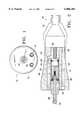
- FIG. 1is an elevational view of the proximal end of the handpiece of the present invention.
- FIG. 2is a schematic, cross-sectional view of a first embodiment of the handpiece of the present invention.
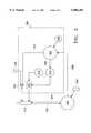
- FIG. 3is a block diagram of a control system that can be used with the surgical handpiece of the present invention.
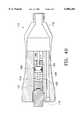
- FIGS. 4A-4Cares schematic, cross-sectional view of a second embodiment of the handpiece of the present invention.
- Handpiece 10 of the present inventiongenerally includes handpiece body 12 having internal irrigation lumen 14, internal aspiration lumen 16 and boiling chamber fluid supply lumen 18.
- Body 12may be made from plastic, metal or ceramic.
- a first embodiment of handpiece 10contains pumping chamber 20 formed between electrode 21 and piston 22.
- Piston 22is sealed within chamber 20 by seal 24 and electrode 21 is sealed within chamber 20 by seal 26 and fluid supply fitting 28.
- pumping chamber 20is supplied with a conductive fluid (e.g. saline solution) through lumen 18.
- Electrical current(preferably RFAC) is delivered to and across electrodes 21 and 23 because of the conductive nature of the fluid.
- RFACRFAC
- Rod 32which is connected to piston 22, is forced distally along with piston 22.
- Piston 22travels distally until it passes vent port 34, thereby venting the excess pressure from chamber 20, and allowing return spring 36 to force piston 22 back toward electrode 21.
- Subsequent pulses of electrical currentform sequential gas bubbles that impart a reciprocal motion to piston 22 and rod 32.
- the size and pressure of the fluid pulse obtained by pumping chamber 20can be varied by varying the length, timing and/or power of the electrical pulse sent to electrodes 21 and 23 and by varying the dimensions of chamber 20.
- the fluidmay be preheated prior to entering pumping chamber 20. Preheating the fluid will decrease the power required by pumping chamber 20 and/or increase the speed at which pressure pulses can be generated.
- pumping chamber 20 and vent port 34may be interconnected in a sealed system, so that no fluid needs to be added to chamber 20 through lumen 18.
- pumping chamber 119 of handpiece 110contains proximal pumping chamber 120 formed between proximal electrode 121 and piston 122 and distal pumping chamber 117 formed between distal electrode 156 and piston 122.
- Pumping chamber 120 and 117contain both a conductive surgical fluid and a gas.
- electrical currentis supplied to proximal electrode 121 and flows through the fluid to electrode 123 located on the proximal end of piston 122., thereby boiling the fluid. As the fluid boils, piston 122 is forced distally, as shown in FIG. 4B.
- FIGS. 4A-4Care identical to the numbers in FIGS. 1-2 except for the addition of "100" in FIGS. 4A-4C.
- any handpiece producing adequate pressure pulse force, rise time and frequencymay also be used.
- control system 300 for use in operating handpiece 310includes control module 347, RF amplifier 312 and function generator 314. Power is supplied to RF amplifier 312 by DC power supply 316, which preferably is an isolated DC power supply.
- Control module 347may be any suitable microprocessor, and may receive input from operator input device 318.
- Function generator 314provides the electric wave form to amplifier 312 and preferably operates at greater than 250 KHz to help minimize corrosion.
- control module 347receives input from surgical console 320.
- Console 320may be any commercially available surgical control console such as the LEGACY® SERIES TWENTY THOUSAND® surgical system available from Alcon Laboratories, Inc., Fort Worth, Tex.
- Console 320is connected to handpiece 310 through irrigation line 322 and aspiration line 324, and the flow through lines 322 and 324 is controlled by the user via footswitch 326.
- Irrigation and aspiration flow rate information in handpiece 310is provided to control module 347 by console 320 via interface 328, which may be connected to the ultrasound handpiece control port on console 320 or to any other output port.
- Control module 347uses footswitch 326 information provided by console 320 and operator input from input device 318 to generate two control signals 330 and 332.
- Signal 332is used to operate pinch valve 334, which controls the fluid flowing from fluid source 336 to handpiece 310. Fluid from fluid source 336 is heated in the manner described herein.
- Signal 330is used to control function generator 314. Based on signal 330, function generator 314 provides a wave form at the operator selected frequency and amplitude determined by the position of footswitch 326 to RF amplifier 312 which is amplified to advance the powered wave form to handpiece 310 to create the desired motion.
Landscapes
- Health & Medical Sciences (AREA)
- Ophthalmology & Optometry (AREA)
- Heart & Thoracic Surgery (AREA)
- Surgery (AREA)
- Engineering & Computer Science (AREA)
- Biomedical Technology (AREA)
- Nuclear Medicine, Radiotherapy & Molecular Imaging (AREA)
- Vascular Medicine (AREA)
- Life Sciences & Earth Sciences (AREA)
- Animal Behavior & Ethology (AREA)
- General Health & Medical Sciences (AREA)
- Public Health (AREA)
- Veterinary Medicine (AREA)
- Surgical Instruments (AREA)
Abstract
Description
This application is a continuation-in-part application of U.S. patent application Ser. No. 09/090,433, filed Jun. 4, 1998.
This invention relates generally to the field of ophthalmic surgery and more particularly to a pumping chamber for use with a surgical handpiece.
During many surgical procedures, particularly microsurgical procedures such as ophthalmic surgery, small mechanical devices or probes are inserted into the surgical field. These different probes have a variety of functions. For example, small scissors are often to used to cut fibrous tissue. Guillotine-type or rotary cutters are used to remove the vitreous from the posterior chamber of an eye or for opening the anterior capsule for cataract surgery. Prior to the present invention, these devices have all used pneumatic or electric drivers. Pneumatic drivers use air pressure pulses to force a plunger against a spring. When the pressure pulse decays, the spring forces the plunger back to its original starting point, thereby imparting reciprocal motion to the plunger. With these types of surgical systems, the pressure pulse is generated in the control console and can travel as far as two meters down the connecting pneumatic tubing before entering the probe. Compliance in the tubing causes degradation of the pressure pulse. Electrical drivers contain miniature electrical motors that can be heavy and relatively expensive, making them less desirable for disposable probes.
Therefore, a need continues to exist for a handpiece driver that is lighter, less expensive than the prior art drivers and that delivers sharp, consistent drive pulses, with faster cut rates and/or rise time.
The present invention improves upon the prior art by providing a surgical handpiece driver having a pumping chamber. The pumping chamber works by boiling a small volume of a fluid. As the fluid boils, it expands rapidly, thereby propelling a piston down the length of the pumping chamber. The piston may be attached to the shaft or rod of a surgical probe and produce reciprocal motion. Alternatively, the piston may be attached to a cam or gear to produce rotary motion.
Accordingly, one objective of the present invention is to provide a surgical handpiece having a pumping chamber.
Another objective of the present invention is to provide a surgical handpiece that is lighter than the prior art handpieces.
Another objective of the present invention is to provide a surgical handpiece that is less expensive.
Another objective of the present invention is to provide a surgical handpiece that delivers sharp, consistent drive pulses, with high speed and/or rise time.
Another objective of the present invention is to provide a surgical handpiece having fast cut rates.
Another objective of the present invention is to provide a surgical handpiece having a wide range of cut rates.
These and other advantages and objectives of the present invention will become apparent from the detailed description and claims that follow.
FIG. 1 is an elevational view of the proximal end of the handpiece of the present invention.
FIG. 2 is a schematic, cross-sectional view of a first embodiment of the handpiece of the present invention.
FIG. 3 is a block diagram of a control system that can be used with the surgical handpiece of the present invention.
FIGS. 4A-4C ares schematic, cross-sectional view of a second embodiment of the handpiece of the present invention.
As best seen in FIG. 2, a first embodiment ofhandpiece 10 containspumping chamber 20 formed betweenelectrode 21 andpiston 22. Asecond electrode 23, is formed on the proximal face ofpiston 22. Piston 22 is sealed withinchamber 20 byseal 24 andelectrode 21 is sealed withinchamber 20 byseal 26 and fluid supply fitting 28.
In operation,pumping chamber 20 is supplied with a conductive fluid (e.g. saline solution) throughlumen 18. Electrical current (preferably RFAC) is delivered to and acrosselectrodes piston 22 distally.Check valve 30 prevents the expanding fluid from enteringlumen 18.Rod 32, which is connected topiston 22, is forced distally along withpiston 22. Piston 22 travels distally until it passesvent port 34, thereby venting the excess pressure fromchamber 20, and allowingreturn spring 36 to forcepiston 22 back towardelectrode 21. Subsequent pulses of electrical current form sequential gas bubbles that impart a reciprocal motion to piston 22 androd 32. The size and pressure of the fluid pulse obtained bypumping chamber 20 can be varied by varying the length, timing and/or power of the electrical pulse sent toelectrodes chamber 20. In addition, the fluid may be preheated prior to enteringpumping chamber 20. Preheating the fluid will decrease the power required bypumping chamber 20 and/or increase the speed at which pressure pulses can be generated.
Alternatively,pumping chamber 20 andvent port 34 may be interconnected in a sealed system, so that no fluid needs to be added tochamber 20 throughlumen 18.
In the second embodiment of the present invention illustrated in FIGS. 4A-4C,pumping chamber 119 ofhandpiece 110 containsproximal pumping chamber 120 formed betweenproximal electrode 121 andpiston 122 anddistal pumping chamber 117 formed betweendistal electrode 156 andpiston 122.Pumping chamber proximal electrode 121 and flows through the fluid toelectrode 123 located on the proximal end of piston 122., thereby boiling the fluid. As the fluid boils,piston 122 is forced distally, as shown in FIG. 4B. Electrical current is then alternatively supplied to distalelectrode 156 and flows through the fluid toelectrode 125 located on the distal end of piston 122., thereby boiling the fluid located indistal pumping chamber 117. The fluid boils inpumping chamber 117 at the same time the steam or gas inpumping chamber 120 is cooling and condensing back to a liquid, andpiston 122 is forced proximally, as shown in FIG. 4C. Alternating the boiling of the fluid betweenpumping chambers forces piston 122 to reciprocate proximally and distally without the use ofspring 36. The numbers in FIGS. 4A-4C are identical to the numbers in FIGS. 1-2 except for the addition of "100" in FIGS. 4A-4C.
While only two embodiments of the handpiece of the present invention is disclosed, any handpiece producing adequate pressure pulse force, rise time and frequency may also be used. For example, any suitable handpiece producing a pressure pulse that permits between 0 and 5000 cycles per minute.
As seen in FIG. 3, one embodiment ofcontrol system 300 for use inoperating handpiece 310 includescontrol module 347,RF amplifier 312 andfunction generator 314. Power is supplied toRF amplifier 312 byDC power supply 316, which preferably is an isolated DC power supply.Control module 347 may be any suitable microprocessor, and may receive input fromoperator input device 318.Function generator 314 provides the electric wave form toamplifier 312 and preferably operates at greater than 250 KHz to help minimize corrosion.
In use,control module 347 receives input fromsurgical console 320.Console 320 may be any commercially available surgical control console such as the LEGACY® SERIES TWENTY THOUSAND® surgical system available from Alcon Laboratories, Inc., Fort Worth, Tex.Console 320 is connected to handpiece 310 throughirrigation line 322 andaspiration line 324, and the flow throughlines footswitch 326. Irrigation and aspiration flow rate information inhandpiece 310 is provided to controlmodule 347 byconsole 320 viainterface 328, which may be connected to the ultrasound handpiece control port onconsole 320 or to any other output port.Control module 347 uses footswitch 326 information provided byconsole 320 and operator input frominput device 318 to generate twocontrol signals Signal 332 is used to operatepinch valve 334, which controls the fluid flowing fromfluid source 336 tohandpiece 310. Fluid fromfluid source 336 is heated in the manner described herein.Signal 330 is used to controlfunction generator 314. Based onsignal 330,function generator 314 provides a wave form at the operator selected frequency and amplitude determined by the position offootswitch 326 toRF amplifier 312 which is amplified to advance the powered wave form to handpiece 310 to create the desired motion.
This description is given for purposes of illustration and explanation. It will be apparent to those skilled in the relevant art that changes and modifications may be made to the invention described above without departing from its scope or spirit. For example, it will be recognized by those skilled in the art that the present invention may be combined with ultrasonic and/or rotating cutting tips to enhance performance.
Claims (6)
1. A surgical handpiece, comprising:
a) a body; and
b) a pumping chamber formed internal to the body between a first electrode and a piston, the piston having a second electrode and being able to reciprocate within the pumping chamber.
2. The handpiece of claim 1 wherein the pumping chamber is capable of boiling a conductive fluid when electrical current is passed between the first electrode and the second electrode.
3. A surgical handpiece, comprising:
a) a body having an internal irrigation lumen and an internal aspiration lumen; and
b) a pumping chamber formed within the body and having a first electrode and a second electrode across which electrical current will flow, the second electrode being formed on a piston that reciprocates within the pumping chamber.
4. The handpiece of claim 3 wherein electrical current flowing across the electrodes is capable of boiling a fluid contained between the electrodes.
5. A surgical handpiece, comprising:
a) a body; and
b) a pumping chamber formed within the body between a proximal electrode and a distal electrode; and
c) a reciprocating piston located within the pumping chamber, the piston separating the pumping chamber into a proximal pumping chamber and a distal pumping chamber.
6. The handpiece of claim 5 wherein the piston reciprocates within the pumping chamber in response to electrical current flowing through the distal electrode and the proximal electrode.
Priority Applications (3)
| Application Number | Priority Date | Filing Date | Title |
|---|---|---|---|
| US09/266,501US6004284A (en) | 1998-06-04 | 1999-03-11 | Surgical handpiece |
| PCT/US2000/000366WO2000053137A1 (en) | 1999-03-11 | 2000-01-07 | Surgical handpiece |
| AU24951/00AAU2495100A (en) | 1999-03-11 | 2000-01-07 | Surgical handpiece |
Applications Claiming Priority (2)
| Application Number | Priority Date | Filing Date | Title |
|---|---|---|---|
| US09/090,433US6080128A (en) | 1998-06-04 | 1998-06-04 | Liquefaction handpiece |
| US09/266,501US6004284A (en) | 1998-06-04 | 1999-03-11 | Surgical handpiece |
Related Parent Applications (1)
| Application Number | Title | Priority Date | Filing Date |
|---|---|---|---|
| US09/090,433Continuation-In-PartUS6080128A (en) | 1998-06-04 | 1998-06-04 | Liquefaction handpiece |
Publications (1)
| Publication Number | Publication Date |
|---|---|
| US6004284Atrue US6004284A (en) | 1999-12-21 |
Family
ID=23014828
Family Applications (1)
| Application Number | Title | Priority Date | Filing Date |
|---|---|---|---|
| US09/266,501Expired - LifetimeUS6004284A (en) | 1998-06-04 | 1999-03-11 | Surgical handpiece |
Country Status (3)
| Country | Link |
|---|---|
| US (1) | US6004284A (en) |
| AU (1) | AU2495100A (en) |
| WO (1) | WO2000053137A1 (en) |
Cited By (18)
| Publication number | Priority date | Publication date | Assignee | Title |
|---|---|---|---|---|
| US6383203B1 (en) | 1999-09-27 | 2002-05-07 | Nidek Co., Ltd. | Surgical apparatus for a vitreous |
| US6478681B1 (en) | 2000-11-27 | 2002-11-12 | Duke University | Magnetic couplings for imparting simultaneous rotary and longitudinal oscillations |
| US6517560B1 (en) | 2000-11-27 | 2003-02-11 | Duke University | Hand-held surgical instruments employing magnetic couplings for simultaneous rotary and longitudinal oscillations of distal workpieces |
| US20100010499A1 (en)* | 2008-07-10 | 2010-01-14 | Cook Incorporated | Hydraulic guidewire advancement system |
| US20100076471A1 (en)* | 2008-09-25 | 2010-03-25 | Bourne John M | Spring-Less Check Valve For A Handpiece |
| US7758585B2 (en)* | 2005-03-16 | 2010-07-20 | Alcon, Inc. | Pumping chamber for a liquefaction handpiece |
| US7849875B2 (en) | 2007-07-31 | 2010-12-14 | Alcon, Inc. | Check valve |
| US8377000B2 (en) | 2010-10-01 | 2013-02-19 | Abbott Laboratories | Enteral feeding apparatus having a feeding set |
| US8377001B2 (en) | 2010-10-01 | 2013-02-19 | Abbott Laboratories | Feeding set for a peristaltic pump system |
| US20130053726A1 (en)* | 2007-10-01 | 2013-02-28 | Suros Surgical Systems, Inc. | Surgical device and method of using same |
| US8689439B2 (en) | 2010-08-06 | 2014-04-08 | Abbott Laboratories | Method for forming a tube for use with a pump delivery system |
| US9615969B2 (en) | 2012-12-18 | 2017-04-11 | Novartis Ag | Multi-port vitrectomy probe with dual cutting edges |
| US9693898B2 (en) | 2014-11-19 | 2017-07-04 | Novartis Ag | Double-acting vitreous probe with contoured port |
| EP4052685A1 (en)* | 2017-05-04 | 2022-09-07 | Carl Zeiss Meditec Cataract Technology Inc. | Devices for ocular surgery |
| US11638660B2 (en) | 2018-06-05 | 2023-05-02 | Carl Zeiss Meditec Cataract Technology Inc. | Ophthalmic microsurgical tools, systems, and methods of use |
| US11730625B2 (en) | 2019-05-17 | 2023-08-22 | Carl Zeiss Meditec Cataract Technology Inc. | Ophthalmic cutting instruments having integrated aspiration pump |
| US11801163B2 (en) | 2019-06-07 | 2023-10-31 | Carl Zeiss Meditec Cataract Technology Inc. | Multi-stage trigger for ophthalmology cutting tool |
| US12285361B2 (en) | 2019-02-01 | 2025-04-29 | Carl Zeiss Meditec Cataract Technology Inc. | Ophthalmic cutting instruments having integrated aspiration pump |
Families Citing this family (1)
| Publication number | Priority date | Publication date | Assignee | Title |
|---|---|---|---|---|
| US8252917B2 (en) | 2003-10-24 | 2012-08-28 | Selexis S.A. | High efficiency gene transfer and expression in mammalian cells by a multiple transfection procedure of MAR sequences |
Citations (36)
| Publication number | Priority date | Publication date | Assignee | Title |
|---|---|---|---|---|
| US3818913A (en)* | 1972-08-30 | 1974-06-25 | M Wallach | Surgical apparatus for removal of tissue |
| US3930505A (en)* | 1974-06-24 | 1976-01-06 | Hydro Pulse Corporation | Surgical apparatus for removal of tissue |
| US4024866A (en)* | 1974-12-02 | 1977-05-24 | Hydro Pulse Corporation | Surgical apparatus for removal of tissue |
| US4246902A (en)* | 1978-03-10 | 1981-01-27 | Miguel Martinez | Surgical cutting instrument |
| US4402817A (en)* | 1981-11-12 | 1983-09-06 | Maget Henri J R | Electrochemical prime mover |
| US4471256A (en)* | 1982-06-14 | 1984-09-11 | Nippon Soken, Inc. | Piezoelectric actuator, and valve apparatus having actuator |
| US4570632A (en)* | 1984-03-16 | 1986-02-18 | Woods Randall L | Cystotome for eye surgery and method of opening lens capsule |
| US4577629A (en)* | 1983-10-28 | 1986-03-25 | Coopervision, Inc. | Surgical cutting instrument for ophthalmic surgery |
| US4597388A (en)* | 1983-12-15 | 1986-07-01 | Trutek Research, Inc. | Apparatus for removing cataracts |
| US4857054A (en)* | 1988-07-15 | 1989-08-15 | Eastman Kodak Company | Perfusion angioplasty catheter with pump assist |
| US4909249A (en)* | 1987-11-05 | 1990-03-20 | The Cooper Companies, Inc. | Surgical cutting instrument |
| US4911161A (en)* | 1987-04-29 | 1990-03-27 | Noetix, Inc. | Capsulectomy cutting apparatus |
| US4915094A (en)* | 1986-06-30 | 1990-04-10 | Technomed International | Apparatus for generating high frequency shock waves of which the electrical supply connection is disposed inside a tubular element, limiting or preventing electro-magnetic leakages |
| US4986827A (en)* | 1987-11-05 | 1991-01-22 | Nestle S.A. | Surgical cutting instrument with reciprocating inner cutter |
| US5019035A (en)* | 1989-06-07 | 1991-05-28 | Alcon Surgical, Inc. | Cutting assembly for surgical cutting instrument |
| US5106364A (en)* | 1989-07-07 | 1992-04-21 | Kabushiki Kaisha Topcon | Surgical cutter |
| US5176628A (en)* | 1989-10-27 | 1993-01-05 | Alcon Surgical, Inc. | Vitreous cutter |
| US5226910A (en)* | 1989-07-05 | 1993-07-13 | Kabushiki Kaisha Topcon | Surgical cutter |
| US5257977A (en)* | 1990-03-22 | 1993-11-02 | Argomed Ltd. | Technique for localized thermal treatment of mammals |
| US5261883A (en)* | 1990-10-26 | 1993-11-16 | Alcon Surgical, Inc. | Portable apparatus for controlling fluid flow to a surgical site |
| US5275607A (en)* | 1991-09-23 | 1994-01-04 | Visionary Medical, Inc. | Intraocular surgical scissors |
| US5284472A (en)* | 1992-10-30 | 1994-02-08 | Allergan, Inc. | Vitreous cutter |
| US5285795A (en)* | 1991-09-12 | 1994-02-15 | Surgical Dynamics, Inc. | Percutaneous discectomy system having a bendable discectomy probe and a steerable cannula |
| US5322504A (en)* | 1992-05-07 | 1994-06-21 | United States Surgical Corporation | Method and apparatus for tissue excision and removal by fluid jet |
| US5549559A (en)* | 1990-03-22 | 1996-08-27 | Argomed Ltd. | Thermal treatment apparatus |
| US5562692A (en)* | 1993-07-26 | 1996-10-08 | Sentinel Medical, Inc. | Fluid jet surgical cutting tool |
| US5591184A (en)* | 1994-10-13 | 1997-01-07 | Sentinel Medical, Inc. | Fluid jet surgical cutting instrument |
| US5624392A (en)* | 1990-05-11 | 1997-04-29 | Saab; Mark A. | Heat transfer catheters and methods of making and using same |
| US5653692A (en)* | 1995-09-07 | 1997-08-05 | Innerdyne Medical, Inc. | Method and system for direct heating of fluid solution in a hollow body organ |
| US5669923A (en)* | 1996-01-24 | 1997-09-23 | Gordon; Mark G. | Anterior capsulotomy device and procedure |
| US5674226A (en)* | 1992-05-07 | 1997-10-07 | Sentinel Medical, Inc. | Method and apparatus for tissue excision and removal by fluid jet |
| US5713864A (en)* | 1995-04-11 | 1998-02-03 | Sims Level 1, Inc. | Integral conductive polymer resistance heated tubing |
| US5865790A (en)* | 1993-07-26 | 1999-02-02 | Surgijet, Inc. | Method and apparatus for thermal phacoemulsification by fluid throttling |
| US5879347A (en)* | 1997-04-25 | 1999-03-09 | Gynecare, Inc. | Apparatus for controlled thermal treatment of tissue |
| US5885243A (en)* | 1996-12-11 | 1999-03-23 | Alcon Laboratories, Inc. | Liquefaction handpiece |
| US5891094A (en)* | 1995-09-07 | 1999-04-06 | Innerdyne, Inc. | System for direct heating of fluid solution in a hollow body organ and methods |
Family Cites Families (2)
| Publication number | Priority date | Publication date | Assignee | Title |
|---|---|---|---|---|
| US5733256A (en)* | 1996-09-26 | 1998-03-31 | Micro Medical Devices | Integrated phacoemulsification system |
| US5989212A (en)* | 1998-06-04 | 1999-11-23 | Alcon Laboratories, Inc. | Pumping chamber for a liquefaction handpiece having a countersink electrode |
- 1999
- 1999-03-11USUS09/266,501patent/US6004284A/ennot_activeExpired - Lifetime
- 2000
- 2000-01-07WOPCT/US2000/000366patent/WO2000053137A1/enactiveApplication Filing
- 2000-01-07AUAU24951/00Apatent/AU2495100A/ennot_activeAbandoned
Patent Citations (36)
| Publication number | Priority date | Publication date | Assignee | Title |
|---|---|---|---|---|
| US3818913A (en)* | 1972-08-30 | 1974-06-25 | M Wallach | Surgical apparatus for removal of tissue |
| US3930505A (en)* | 1974-06-24 | 1976-01-06 | Hydro Pulse Corporation | Surgical apparatus for removal of tissue |
| US4024866A (en)* | 1974-12-02 | 1977-05-24 | Hydro Pulse Corporation | Surgical apparatus for removal of tissue |
| US4246902A (en)* | 1978-03-10 | 1981-01-27 | Miguel Martinez | Surgical cutting instrument |
| US4402817A (en)* | 1981-11-12 | 1983-09-06 | Maget Henri J R | Electrochemical prime mover |
| US4471256A (en)* | 1982-06-14 | 1984-09-11 | Nippon Soken, Inc. | Piezoelectric actuator, and valve apparatus having actuator |
| US4577629A (en)* | 1983-10-28 | 1986-03-25 | Coopervision, Inc. | Surgical cutting instrument for ophthalmic surgery |
| US4597388A (en)* | 1983-12-15 | 1986-07-01 | Trutek Research, Inc. | Apparatus for removing cataracts |
| US4570632A (en)* | 1984-03-16 | 1986-02-18 | Woods Randall L | Cystotome for eye surgery and method of opening lens capsule |
| US4915094A (en)* | 1986-06-30 | 1990-04-10 | Technomed International | Apparatus for generating high frequency shock waves of which the electrical supply connection is disposed inside a tubular element, limiting or preventing electro-magnetic leakages |
| US4911161A (en)* | 1987-04-29 | 1990-03-27 | Noetix, Inc. | Capsulectomy cutting apparatus |
| US4909249A (en)* | 1987-11-05 | 1990-03-20 | The Cooper Companies, Inc. | Surgical cutting instrument |
| US4986827A (en)* | 1987-11-05 | 1991-01-22 | Nestle S.A. | Surgical cutting instrument with reciprocating inner cutter |
| US4857054A (en)* | 1988-07-15 | 1989-08-15 | Eastman Kodak Company | Perfusion angioplasty catheter with pump assist |
| US5019035A (en)* | 1989-06-07 | 1991-05-28 | Alcon Surgical, Inc. | Cutting assembly for surgical cutting instrument |
| US5226910A (en)* | 1989-07-05 | 1993-07-13 | Kabushiki Kaisha Topcon | Surgical cutter |
| US5106364A (en)* | 1989-07-07 | 1992-04-21 | Kabushiki Kaisha Topcon | Surgical cutter |
| US5176628A (en)* | 1989-10-27 | 1993-01-05 | Alcon Surgical, Inc. | Vitreous cutter |
| US5257977A (en)* | 1990-03-22 | 1993-11-02 | Argomed Ltd. | Technique for localized thermal treatment of mammals |
| US5549559A (en)* | 1990-03-22 | 1996-08-27 | Argomed Ltd. | Thermal treatment apparatus |
| US5624392A (en)* | 1990-05-11 | 1997-04-29 | Saab; Mark A. | Heat transfer catheters and methods of making and using same |
| US5261883A (en)* | 1990-10-26 | 1993-11-16 | Alcon Surgical, Inc. | Portable apparatus for controlling fluid flow to a surgical site |
| US5285795A (en)* | 1991-09-12 | 1994-02-15 | Surgical Dynamics, Inc. | Percutaneous discectomy system having a bendable discectomy probe and a steerable cannula |
| US5275607A (en)* | 1991-09-23 | 1994-01-04 | Visionary Medical, Inc. | Intraocular surgical scissors |
| US5322504A (en)* | 1992-05-07 | 1994-06-21 | United States Surgical Corporation | Method and apparatus for tissue excision and removal by fluid jet |
| US5674226A (en)* | 1992-05-07 | 1997-10-07 | Sentinel Medical, Inc. | Method and apparatus for tissue excision and removal by fluid jet |
| US5284472A (en)* | 1992-10-30 | 1994-02-08 | Allergan, Inc. | Vitreous cutter |
| US5562692A (en)* | 1993-07-26 | 1996-10-08 | Sentinel Medical, Inc. | Fluid jet surgical cutting tool |
| US5865790A (en)* | 1993-07-26 | 1999-02-02 | Surgijet, Inc. | Method and apparatus for thermal phacoemulsification by fluid throttling |
| US5591184A (en)* | 1994-10-13 | 1997-01-07 | Sentinel Medical, Inc. | Fluid jet surgical cutting instrument |
| US5713864A (en)* | 1995-04-11 | 1998-02-03 | Sims Level 1, Inc. | Integral conductive polymer resistance heated tubing |
| US5653692A (en)* | 1995-09-07 | 1997-08-05 | Innerdyne Medical, Inc. | Method and system for direct heating of fluid solution in a hollow body organ |
| US5891094A (en)* | 1995-09-07 | 1999-04-06 | Innerdyne, Inc. | System for direct heating of fluid solution in a hollow body organ and methods |
| US5669923A (en)* | 1996-01-24 | 1997-09-23 | Gordon; Mark G. | Anterior capsulotomy device and procedure |
| US5885243A (en)* | 1996-12-11 | 1999-03-23 | Alcon Laboratories, Inc. | Liquefaction handpiece |
| US5879347A (en)* | 1997-04-25 | 1999-03-09 | Gynecare, Inc. | Apparatus for controlled thermal treatment of tissue |
Cited By (27)
| Publication number | Priority date | Publication date | Assignee | Title |
|---|---|---|---|---|
| US6383203B1 (en) | 1999-09-27 | 2002-05-07 | Nidek Co., Ltd. | Surgical apparatus for a vitreous |
| US6478681B1 (en) | 2000-11-27 | 2002-11-12 | Duke University | Magnetic couplings for imparting simultaneous rotary and longitudinal oscillations |
| US6517560B1 (en) | 2000-11-27 | 2003-02-11 | Duke University | Hand-held surgical instruments employing magnetic couplings for simultaneous rotary and longitudinal oscillations of distal workpieces |
| US7758585B2 (en)* | 2005-03-16 | 2010-07-20 | Alcon, Inc. | Pumping chamber for a liquefaction handpiece |
| US7849875B2 (en) | 2007-07-31 | 2010-12-14 | Alcon, Inc. | Check valve |
| US20130053726A1 (en)* | 2007-10-01 | 2013-02-28 | Suros Surgical Systems, Inc. | Surgical device and method of using same |
| US8808200B2 (en)* | 2007-10-01 | 2014-08-19 | Suros Surgical Systems, Inc. | Surgical device and method of using same |
| US20100010499A1 (en)* | 2008-07-10 | 2010-01-14 | Cook Incorporated | Hydraulic guidewire advancement system |
| US8313493B2 (en)* | 2008-07-10 | 2012-11-20 | Cook Medical Technologies Llc | Hydraulic guidewire advancement system |
| US20100076471A1 (en)* | 2008-09-25 | 2010-03-25 | Bourne John M | Spring-Less Check Valve For A Handpiece |
| US8291933B2 (en) | 2008-09-25 | 2012-10-23 | Novartis Ag | Spring-less check valve for a handpiece |
| US8689439B2 (en) | 2010-08-06 | 2014-04-08 | Abbott Laboratories | Method for forming a tube for use with a pump delivery system |
| US8377001B2 (en) | 2010-10-01 | 2013-02-19 | Abbott Laboratories | Feeding set for a peristaltic pump system |
| US8377000B2 (en) | 2010-10-01 | 2013-02-19 | Abbott Laboratories | Enteral feeding apparatus having a feeding set |
| US9615969B2 (en) | 2012-12-18 | 2017-04-11 | Novartis Ag | Multi-port vitrectomy probe with dual cutting edges |
| US9693898B2 (en) | 2014-11-19 | 2017-07-04 | Novartis Ag | Double-acting vitreous probe with contoured port |
| JP2022166212A (en)* | 2017-05-04 | 2022-11-01 | カール・ツァイス・メディテック・キャタラクト・テクノロジー・インコーポレイテッド | Ophthalmic surgical device and method |
| EP4052686A1 (en)* | 2017-05-04 | 2022-09-07 | Carl Zeiss Meditec Cataract Technology Inc. | Devices for ocular surgery |
| EP4052685A1 (en)* | 2017-05-04 | 2022-09-07 | Carl Zeiss Meditec Cataract Technology Inc. | Devices for ocular surgery |
| JP2022166213A (en)* | 2017-05-04 | 2022-11-01 | カール・ツァイス・メディテック・キャタラクト・テクノロジー・インコーポレイテッド | Devices and methods for ocular surgery |
| US11607338B2 (en) | 2017-05-04 | 2023-03-21 | Carl Zeiss Meditec Cataract Technology Inc. | Devices and methods for ocular surgery |
| US11622888B2 (en) | 2017-05-04 | 2023-04-11 | Carl Zeiss Meditec Cataract Technology Inc. | Devices and methods for ocular surgery |
| US11622887B2 (en) | 2017-05-04 | 2023-04-11 | Carl Zeiss Meditec Cataract Technology Inc. | Devices and methods for ocular surgery |
| US11638660B2 (en) | 2018-06-05 | 2023-05-02 | Carl Zeiss Meditec Cataract Technology Inc. | Ophthalmic microsurgical tools, systems, and methods of use |
| US12285361B2 (en) | 2019-02-01 | 2025-04-29 | Carl Zeiss Meditec Cataract Technology Inc. | Ophthalmic cutting instruments having integrated aspiration pump |
| US11730625B2 (en) | 2019-05-17 | 2023-08-22 | Carl Zeiss Meditec Cataract Technology Inc. | Ophthalmic cutting instruments having integrated aspiration pump |
| US11801163B2 (en) | 2019-06-07 | 2023-10-31 | Carl Zeiss Meditec Cataract Technology Inc. | Multi-stage trigger for ophthalmology cutting tool |
Also Published As
| Publication number | Publication date |
|---|---|
| WO2000053137A1 (en) | 2000-09-14 |
| AU2495100A (en) | 2000-09-28 |
Similar Documents
| Publication | Publication Date | Title |
|---|---|---|
| US6004284A (en) | Surgical handpiece | |
| JP4050759B2 (en) | Liquefaction handpiece | |
| EP1199054B1 (en) | Liquefracture handpiece | |
| CA2382533C (en) | Liquefracture handpiece | |
| AU767867B2 (en) | Liquefracture handpiece tip | |
| US6315755B1 (en) | Method of controlling a liquefracture handpiece | |
| US6648847B2 (en) | Method of operating a liquefracture handpiece | |
| US6579270B2 (en) | Liquefracture handpiece tip | |
| US6428508B1 (en) | Pulsed vacuum cataract removal system | |
| JP2003512132A (en) | Tip for liquefaction crushing handpiece | |
| JP2000005219A (en) | Control system for liquefying handpiece | |
| MXPA01005714A (en) | Pumping chamber for a liquefracture handpiece |
Legal Events
| Date | Code | Title | Description |
|---|---|---|---|
| AS | Assignment | Owner name:ALCON LABORATORIES, INC., TEXAS Free format text:ASSIGNMENT OF ASSIGNORS INTEREST;ASSIGNORS:SUSSMAN, GLENN;CAPETAN, THOMAS G.;REEL/FRAME:009822/0538;SIGNING DATES FROM 19990310 TO 19990311 | |
| STCF | Information on status: patent grant | Free format text:PATENTED CASE | |
| AS | Assignment | Owner name:ALCON MANUFACTURING, LTD., TEXAS Free format text:ASSIGNMENT OF ASSIGNORS INTEREST;ASSIGNOR:ALCON LABORATORIES, INC.;REEL/FRAME:011667/0559 Effective date:20010322 | |
| FPAY | Fee payment | Year of fee payment:4 | |
| FPAY | Fee payment | Year of fee payment:8 | |
| AS | Assignment | Owner name:ALCON RESEARCH, LTD., TEXAS Free format text:MERGER;ASSIGNOR:ALCON MANUFACTURING, LTD.;REEL/FRAME:021266/0729 Effective date:20080101 Owner name:ALCON RESEARCH, LTD.,TEXAS Free format text:MERGER;ASSIGNOR:ALCON MANUFACTURING, LTD.;REEL/FRAME:021266/0729 Effective date:20080101 | |
| FPAY | Fee payment | Year of fee payment:12 |