US6003977A - Bubble valving for ink-jet printheads - Google Patents
Bubble valving for ink-jet printheadsDownload PDFInfo
- Publication number
- US6003977A US6003977AUS08/692,905US69290596AUS6003977AUS 6003977 AUS6003977 AUS 6003977AUS 69290596 AUS69290596 AUS 69290596AUS 6003977 AUS6003977 AUS 6003977A
- Authority
- US
- United States
- Prior art keywords
- chamber
- ink
- inlet
- heating member
- channel
- Prior art date
- Legal status (The legal status is an assumption and is not a legal conclusion. Google has not performed a legal analysis and makes no representation as to the accuracy of the status listed.)
- Expired - Lifetime
Links
Images


Classifications
- B—PERFORMING OPERATIONS; TRANSPORTING
- B41—PRINTING; LINING MACHINES; TYPEWRITERS; STAMPS
- B41J—TYPEWRITERS; SELECTIVE PRINTING MECHANISMS, i.e. MECHANISMS PRINTING OTHERWISE THAN FROM A FORME; CORRECTION OF TYPOGRAPHICAL ERRORS
- B41J2/00—Typewriters or selective printing mechanisms characterised by the printing or marking process for which they are designed
- B41J2/005—Typewriters or selective printing mechanisms characterised by the printing or marking process for which they are designed characterised by bringing liquid or particles selectively into contact with a printing material
- B41J2/01—Ink jet
- B41J2/135—Nozzles
- B41J2/14—Structure thereof only for on-demand ink jet heads
- B41J2/14016—Structure of bubble jet print heads
- B41J2/14032—Structure of the pressure chamber
- B41J2/1404—Geometrical characteristics
- B—PERFORMING OPERATIONS; TRANSPORTING
- B41—PRINTING; LINING MACHINES; TYPEWRITERS; STAMPS
- B41J—TYPEWRITERS; SELECTIVE PRINTING MECHANISMS, i.e. MECHANISMS PRINTING OTHERWISE THAN FROM A FORME; CORRECTION OF TYPOGRAPHICAL ERRORS
- B41J2/00—Typewriters or selective printing mechanisms characterised by the printing or marking process for which they are designed
- B41J2/005—Typewriters or selective printing mechanisms characterised by the printing or marking process for which they are designed characterised by bringing liquid or particles selectively into contact with a printing material
- B41J2/01—Ink jet
- B41J2/015—Ink jet characterised by the jet generation process
- B41J2/04—Ink jet characterised by the jet generation process generating single droplets or particles on demand
- B41J2/045—Ink jet characterised by the jet generation process generating single droplets or particles on demand by pressure, e.g. electromechanical transducers
- B41J2/04501—Control methods or devices therefor, e.g. driver circuits, control circuits
- B41J2/04543—Block driving
- B—PERFORMING OPERATIONS; TRANSPORTING
- B41—PRINTING; LINING MACHINES; TYPEWRITERS; STAMPS
- B41J—TYPEWRITERS; SELECTIVE PRINTING MECHANISMS, i.e. MECHANISMS PRINTING OTHERWISE THAN FROM A FORME; CORRECTION OF TYPOGRAPHICAL ERRORS
- B41J2/00—Typewriters or selective printing mechanisms characterised by the printing or marking process for which they are designed
- B41J2/005—Typewriters or selective printing mechanisms characterised by the printing or marking process for which they are designed characterised by bringing liquid or particles selectively into contact with a printing material
- B41J2/01—Ink jet
- B41J2/015—Ink jet characterised by the jet generation process
- B41J2/04—Ink jet characterised by the jet generation process generating single droplets or particles on demand
- B41J2/045—Ink jet characterised by the jet generation process generating single droplets or particles on demand by pressure, e.g. electromechanical transducers
- B41J2/04501—Control methods or devices therefor, e.g. driver circuits, control circuits
- B41J2/04546—Multiplexing
- B—PERFORMING OPERATIONS; TRANSPORTING
- B41—PRINTING; LINING MACHINES; TYPEWRITERS; STAMPS
- B41J—TYPEWRITERS; SELECTIVE PRINTING MECHANISMS, i.e. MECHANISMS PRINTING OTHERWISE THAN FROM A FORME; CORRECTION OF TYPOGRAPHICAL ERRORS
- B41J2/00—Typewriters or selective printing mechanisms characterised by the printing or marking process for which they are designed
- B41J2/005—Typewriters or selective printing mechanisms characterised by the printing or marking process for which they are designed characterised by bringing liquid or particles selectively into contact with a printing material
- B41J2/01—Ink jet
- B41J2/015—Ink jet characterised by the jet generation process
- B41J2/04—Ink jet characterised by the jet generation process generating single droplets or particles on demand
- B41J2/045—Ink jet characterised by the jet generation process generating single droplets or particles on demand by pressure, e.g. electromechanical transducers
- B41J2/04501—Control methods or devices therefor, e.g. driver circuits, control circuits
- B41J2/04548—Details of power line section of control circuit
- B—PERFORMING OPERATIONS; TRANSPORTING
- B41—PRINTING; LINING MACHINES; TYPEWRITERS; STAMPS
- B41J—TYPEWRITERS; SELECTIVE PRINTING MECHANISMS, i.e. MECHANISMS PRINTING OTHERWISE THAN FROM A FORME; CORRECTION OF TYPOGRAPHICAL ERRORS
- B41J2/00—Typewriters or selective printing mechanisms characterised by the printing or marking process for which they are designed
- B41J2/005—Typewriters or selective printing mechanisms characterised by the printing or marking process for which they are designed characterised by bringing liquid or particles selectively into contact with a printing material
- B41J2/01—Ink jet
- B41J2/015—Ink jet characterised by the jet generation process
- B41J2/04—Ink jet characterised by the jet generation process generating single droplets or particles on demand
- B41J2/045—Ink jet characterised by the jet generation process generating single droplets or particles on demand by pressure, e.g. electromechanical transducers
- B41J2/04501—Control methods or devices therefor, e.g. driver circuits, control circuits
- B41J2/0458—Control methods or devices therefor, e.g. driver circuits, control circuits controlling heads based on heating elements forming bubbles
- B—PERFORMING OPERATIONS; TRANSPORTING
- B41—PRINTING; LINING MACHINES; TYPEWRITERS; STAMPS
- B41J—TYPEWRITERS; SELECTIVE PRINTING MECHANISMS, i.e. MECHANISMS PRINTING OTHERWISE THAN FROM A FORME; CORRECTION OF TYPOGRAPHICAL ERRORS
- B41J2/00—Typewriters or selective printing mechanisms characterised by the printing or marking process for which they are designed
- B41J2/005—Typewriters or selective printing mechanisms characterised by the printing or marking process for which they are designed characterised by bringing liquid or particles selectively into contact with a printing material
- B41J2/01—Ink jet
- B41J2/135—Nozzles
- B41J2/14—Structure thereof only for on-demand ink jet heads
- B41J2/14016—Structure of bubble jet print heads
- B41J2/14072—Electrical connections, e.g. details on electrodes, connecting the chip to the outside...
- B—PERFORMING OPERATIONS; TRANSPORTING
- B41—PRINTING; LINING MACHINES; TYPEWRITERS; STAMPS
- B41J—TYPEWRITERS; SELECTIVE PRINTING MECHANISMS, i.e. MECHANISMS PRINTING OTHERWISE THAN FROM A FORME; CORRECTION OF TYPOGRAPHICAL ERRORS
- B41J2/00—Typewriters or selective printing mechanisms characterised by the printing or marking process for which they are designed
- B41J2/005—Typewriters or selective printing mechanisms characterised by the printing or marking process for which they are designed characterised by bringing liquid or particles selectively into contact with a printing material
- B41J2/01—Ink jet
- B41J2/135—Nozzles
- B41J2/14—Structure thereof only for on-demand ink jet heads
- B41J2/14016—Structure of bubble jet print heads
- B41J2/1408—Structure dealing with thermal variations, e.g. cooling device, thermal coefficients of materials
- B—PERFORMING OPERATIONS; TRANSPORTING
- B41—PRINTING; LINING MACHINES; TYPEWRITERS; STAMPS
- B41J—TYPEWRITERS; SELECTIVE PRINTING MECHANISMS, i.e. MECHANISMS PRINTING OTHERWISE THAN FROM A FORME; CORRECTION OF TYPOGRAPHICAL ERRORS
- B41J2/00—Typewriters or selective printing mechanisms characterised by the printing or marking process for which they are designed
- B41J2/005—Typewriters or selective printing mechanisms characterised by the printing or marking process for which they are designed characterised by bringing liquid or particles selectively into contact with a printing material
- B41J2/01—Ink jet
- B41J2/135—Nozzles
- B41J2/14—Structure thereof only for on-demand ink jet heads
- B41J2/14016—Structure of bubble jet print heads
- B41J2/14088—Structure of heating means
- B41J2/14112—Resistive element
- B41J2/14129—Layer structure
- B—PERFORMING OPERATIONS; TRANSPORTING
- B41—PRINTING; LINING MACHINES; TYPEWRITERS; STAMPS
- B41J—TYPEWRITERS; SELECTIVE PRINTING MECHANISMS, i.e. MECHANISMS PRINTING OTHERWISE THAN FROM A FORME; CORRECTION OF TYPOGRAPHICAL ERRORS
- B41J2/00—Typewriters or selective printing mechanisms characterised by the printing or marking process for which they are designed
- B41J2/005—Typewriters or selective printing mechanisms characterised by the printing or marking process for which they are designed characterised by bringing liquid or particles selectively into contact with a printing material
- B41J2/01—Ink jet
- B41J2/135—Nozzles
- B41J2/14—Structure thereof only for on-demand ink jet heads
- B41J2/1433—Structure of nozzle plates
- B—PERFORMING OPERATIONS; TRANSPORTING
- B41—PRINTING; LINING MACHINES; TYPEWRITERS; STAMPS
- B41J—TYPEWRITERS; SELECTIVE PRINTING MECHANISMS, i.e. MECHANISMS PRINTING OTHERWISE THAN FROM A FORME; CORRECTION OF TYPOGRAPHICAL ERRORS
- B41J2/00—Typewriters or selective printing mechanisms characterised by the printing or marking process for which they are designed
- B41J2/005—Typewriters or selective printing mechanisms characterised by the printing or marking process for which they are designed characterised by bringing liquid or particles selectively into contact with a printing material
- B41J2/01—Ink jet
- B41J2/135—Nozzles
- B41J2/16—Production of nozzles
- B41J2/1601—Production of bubble jet print heads
- B41J2/1603—Production of bubble jet print heads of the front shooter type
- B—PERFORMING OPERATIONS; TRANSPORTING
- B41—PRINTING; LINING MACHINES; TYPEWRITERS; STAMPS
- B41J—TYPEWRITERS; SELECTIVE PRINTING MECHANISMS, i.e. MECHANISMS PRINTING OTHERWISE THAN FROM A FORME; CORRECTION OF TYPOGRAPHICAL ERRORS
- B41J2/00—Typewriters or selective printing mechanisms characterised by the printing or marking process for which they are designed
- B41J2/005—Typewriters or selective printing mechanisms characterised by the printing or marking process for which they are designed characterised by bringing liquid or particles selectively into contact with a printing material
- B41J2/01—Ink jet
- B41J2/135—Nozzles
- B41J2/16—Production of nozzles
- B41J2/1621—Manufacturing processes
- B41J2/1623—Manufacturing processes bonding and adhesion
- B—PERFORMING OPERATIONS; TRANSPORTING
- B41—PRINTING; LINING MACHINES; TYPEWRITERS; STAMPS
- B41J—TYPEWRITERS; SELECTIVE PRINTING MECHANISMS, i.e. MECHANISMS PRINTING OTHERWISE THAN FROM A FORME; CORRECTION OF TYPOGRAPHICAL ERRORS
- B41J2/00—Typewriters or selective printing mechanisms characterised by the printing or marking process for which they are designed
- B41J2/005—Typewriters or selective printing mechanisms characterised by the printing or marking process for which they are designed characterised by bringing liquid or particles selectively into contact with a printing material
- B41J2/01—Ink jet
- B41J2/135—Nozzles
- B41J2/16—Production of nozzles
- B41J2/1621—Manufacturing processes
- B41J2/1626—Manufacturing processes etching
- B—PERFORMING OPERATIONS; TRANSPORTING
- B41—PRINTING; LINING MACHINES; TYPEWRITERS; STAMPS
- B41J—TYPEWRITERS; SELECTIVE PRINTING MECHANISMS, i.e. MECHANISMS PRINTING OTHERWISE THAN FROM A FORME; CORRECTION OF TYPOGRAPHICAL ERRORS
- B41J2/00—Typewriters or selective printing mechanisms characterised by the printing or marking process for which they are designed
- B41J2/005—Typewriters or selective printing mechanisms characterised by the printing or marking process for which they are designed characterised by bringing liquid or particles selectively into contact with a printing material
- B41J2/01—Ink jet
- B41J2/135—Nozzles
- B41J2/16—Production of nozzles
- B41J2/1621—Manufacturing processes
- B41J2/1631—Manufacturing processes photolithography
- B—PERFORMING OPERATIONS; TRANSPORTING
- B41—PRINTING; LINING MACHINES; TYPEWRITERS; STAMPS
- B41J—TYPEWRITERS; SELECTIVE PRINTING MECHANISMS, i.e. MECHANISMS PRINTING OTHERWISE THAN FROM A FORME; CORRECTION OF TYPOGRAPHICAL ERRORS
- B41J2/00—Typewriters or selective printing mechanisms characterised by the printing or marking process for which they are designed
- B41J2/005—Typewriters or selective printing mechanisms characterised by the printing or marking process for which they are designed characterised by bringing liquid or particles selectively into contact with a printing material
- B41J2/01—Ink jet
- B41J2/135—Nozzles
- B41J2/16—Production of nozzles
- B41J2/1621—Manufacturing processes
- B41J2/1632—Manufacturing processes machining
- B41J2/1634—Manufacturing processes machining laser machining
- B—PERFORMING OPERATIONS; TRANSPORTING
- B41—PRINTING; LINING MACHINES; TYPEWRITERS; STAMPS
- B41J—TYPEWRITERS; SELECTIVE PRINTING MECHANISMS, i.e. MECHANISMS PRINTING OTHERWISE THAN FROM A FORME; CORRECTION OF TYPOGRAPHICAL ERRORS
- B41J2/00—Typewriters or selective printing mechanisms characterised by the printing or marking process for which they are designed
- B41J2/005—Typewriters or selective printing mechanisms characterised by the printing or marking process for which they are designed characterised by bringing liquid or particles selectively into contact with a printing material
- B41J2/01—Ink jet
- B41J2/135—Nozzles
- B41J2/16—Production of nozzles
- B41J2/1621—Manufacturing processes
- B41J2/1635—Manufacturing processes dividing the wafer into individual chips
- B—PERFORMING OPERATIONS; TRANSPORTING
- B41—PRINTING; LINING MACHINES; TYPEWRITERS; STAMPS
- B41J—TYPEWRITERS; SELECTIVE PRINTING MECHANISMS, i.e. MECHANISMS PRINTING OTHERWISE THAN FROM A FORME; CORRECTION OF TYPOGRAPHICAL ERRORS
- B41J2/00—Typewriters or selective printing mechanisms characterised by the printing or marking process for which they are designed
- B41J2/005—Typewriters or selective printing mechanisms characterised by the printing or marking process for which they are designed characterised by bringing liquid or particles selectively into contact with a printing material
- B41J2/01—Ink jet
- B41J2/135—Nozzles
- B41J2/16—Production of nozzles
- B41J2/1621—Manufacturing processes
- B41J2/1637—Manufacturing processes molding
- B41J2/1639—Manufacturing processes molding sacrificial molding
- B—PERFORMING OPERATIONS; TRANSPORTING
- B41—PRINTING; LINING MACHINES; TYPEWRITERS; STAMPS
- B41J—TYPEWRITERS; SELECTIVE PRINTING MECHANISMS, i.e. MECHANISMS PRINTING OTHERWISE THAN FROM A FORME; CORRECTION OF TYPOGRAPHICAL ERRORS
- B41J2/00—Typewriters or selective printing mechanisms characterised by the printing or marking process for which they are designed
- B41J2/005—Typewriters or selective printing mechanisms characterised by the printing or marking process for which they are designed characterised by bringing liquid or particles selectively into contact with a printing material
- B41J2/01—Ink jet
- B41J2/135—Nozzles
- B41J2/16—Production of nozzles
- B41J2/1621—Manufacturing processes
- B41J2/164—Manufacturing processes thin film formation
- B41J2/1643—Manufacturing processes thin film formation thin film formation by plating
- B—PERFORMING OPERATIONS; TRANSPORTING
- B41—PRINTING; LINING MACHINES; TYPEWRITERS; STAMPS
- B41J—TYPEWRITERS; SELECTIVE PRINTING MECHANISMS, i.e. MECHANISMS PRINTING OTHERWISE THAN FROM A FORME; CORRECTION OF TYPOGRAPHICAL ERRORS
- B41J2/00—Typewriters or selective printing mechanisms characterised by the printing or marking process for which they are designed
- B41J2/005—Typewriters or selective printing mechanisms characterised by the printing or marking process for which they are designed characterised by bringing liquid or particles selectively into contact with a printing material
- B41J2/01—Ink jet
- B41J2/135—Nozzles
- B41J2/16—Production of nozzles
- B41J2/1621—Manufacturing processes
- B41J2/164—Manufacturing processes thin film formation
- B41J2/1645—Manufacturing processes thin film formation thin film formation by spincoating
- B—PERFORMING OPERATIONS; TRANSPORTING
- B41—PRINTING; LINING MACHINES; TYPEWRITERS; STAMPS
- B41J—TYPEWRITERS; SELECTIVE PRINTING MECHANISMS, i.e. MECHANISMS PRINTING OTHERWISE THAN FROM A FORME; CORRECTION OF TYPOGRAPHICAL ERRORS
- B41J2/00—Typewriters or selective printing mechanisms characterised by the printing or marking process for which they are designed
- B41J2/005—Typewriters or selective printing mechanisms characterised by the printing or marking process for which they are designed characterised by bringing liquid or particles selectively into contact with a printing material
- B41J2/01—Ink jet
- B41J2/135—Nozzles
- B41J2/14—Structure thereof only for on-demand ink jet heads
- B41J2/14016—Structure of bubble jet print heads
- B41J2002/14169—Bubble vented to the ambience
- B—PERFORMING OPERATIONS; TRANSPORTING
- B41—PRINTING; LINING MACHINES; TYPEWRITERS; STAMPS
- B41J—TYPEWRITERS; SELECTIVE PRINTING MECHANISMS, i.e. MECHANISMS PRINTING OTHERWISE THAN FROM A FORME; CORRECTION OF TYPOGRAPHICAL ERRORS
- B41J2/00—Typewriters or selective printing mechanisms characterised by the printing or marking process for which they are designed
- B41J2/005—Typewriters or selective printing mechanisms characterised by the printing or marking process for which they are designed characterised by bringing liquid or particles selectively into contact with a printing material
- B41J2/01—Ink jet
- B41J2/135—Nozzles
- B41J2/14—Structure thereof only for on-demand ink jet heads
- B41J2002/14387—Front shooter
Definitions
- the present inventiongenerally relates to the control of fluid flow within an ink-jet printhead as ink droplets are ejected from the printhead.
- An ink-jet printerincludes a pen in which small droplets of ink are formed and ejected toward a printing medium.
- Such pensinclude a printhead having an orifice member or plate that has several very small orifices through which the ink droplets are ejected. Adjacent to the orifices are ink chambers, where ink resides prior to ejection through the orifice. Ink is delivered to the ink chambers through ink channels that are in fluid communication with an ink supply.
- the ink supplymay be, for example, contained in a reservoir portion of the pen.
- Ejection of an ink droplet through an orificemay be accomplished by quickly heating a volume of ink within the adjacent ink chamber. This thermal process causes ink within the chamber to superheat and form a vapor bubble. Formation of thermal ink-jet vapor bubble is known as nucleation. The rapid expansion of the bubble forces a drop of ink through the orifice. This process is called "firing.”
- the ink in the chamberis typically heated with a resistor that is aligned with the orifice.
- the ink chamberis refilled by capillary force with ink from the ink channel, thus readying the system for firing another droplet.
- the inertia of the moving inkcauses some of the ink to bulge out of the orifice. Because ink within the pen is generally kept at a slightly positive back pressure (that is, a pressure slightly lower than ambient), the bulging portion of the ink immediately recoils into the ink chamber. This reciprocating motion diminishes over a few cycles and eventually stops or damps out.
- the ejected dropletwill be large and dumbbell shaped, and slow moving. Conversely, if the droplet is ejected when ink is recoiling from the orifice, the ejected droplet will be small and spear shaped, and move undesirably fast. Between these two extremes, as the chamber ink motion damps out, well-formed drops are produced for optimum print quality. Thus, print speed (that is, the rate at which droplets are ejected) must be sufficiently slow to allow the motion of the chamber to damp out between each droplet firing. The time period required for the ink motion to damp sufficiently may be referred to as the damping interval.
- ink chamber and ink channel geometrymay be optimized.
- ink channel length and areamay be constructed to restrict the ink flow rate into and out of the chamber, thereby to reduce the reciprocating motion of chamber refill ink (hence, lessen the damping interval).
- ink channelshave been relatively long with respect to the area, hence the length of the channel is a necessarily important consideration in optimizing damping characteristics of the channel.
- Prior ink-jet printheadsare also susceptible to ink "blowback" during droplet ejection.
- Blowbackresults when some ink in the chamber is forced back into the adjacent part of the channel upon firing. Blowback occurs because the ink in the chamber is not separated from the ink in the channel. Accordingly, upon firing, a large portion of ink affected by the expanding bubble within the chamber is blown back into the channel instead of out the orifice. Blowback increases the amount of energy necessary for ejection of droplets from the chamber (“turn on energy" or TOE) because only a portion of the entire volume of ink in the chamber is actually ejected. A higher TOE results in excessive printhead heating.
- turn on energyor TOE
- Excessive printhead heatingalso generates bubbles from air dissolved in the ink and causes prenucleation of the ink vapor bubble. Air bubbles within the ink and prenucleation of the vapor bubble result in a poor ink droplet formation and, thus, poor print quality.
- Components of the printhead in the vicinity of the vapor bubbleare susceptible to damage from cavitation as the vapor bubble collapses between firing intervals.
- Particularly susceptible to damage from cavitationis the resistor.
- a thin protective passivation layeris typically applied over the resistor. The application of a passivation layer over the resistor, however, increases the TOE necessary for ejecting droplets. Put another way, the trade-off in efforts to reduce TOE by thinning the passivation layer is reduction in the protection against cavitation damage of the resistor.
- blowback resistance attributable to this bubble valvingraises the system thermal efficiency, lowering TOE.
- a lower TOEreduces printhead heating. Reducing printhead heating helps maintain a steady operating temperature, which provides uniform print quality.
- the flow length of the inletwhich is the distance between the ink chamber and ink channel through the inlet, is relatively short.
- the volume of ink in the ink channelis substantially greater than that of the ink inlet.
- the inletis arranged so that the ink flows into the chamber along a flow path that, in preferred embodiments, is substantially parallel to the central axis of the orifice, along which axis ink droplets are expelled from the chamber.
- the flow of the ink to refill the chamberwhich flow commences as the vapor bubble begins to collapse, provides momentum for lifting the collapsing bubble from the resistor so that the eventual collapse point of the bubble is displaced from the resistor, thereby minimizing the damaging effects of cavitation on the resistor that would otherwise occur were the vapor bubble to collapse substantially on the surface of the resistor.
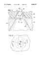
- FIG. 1is a perspective view of an ink-jet pen that incorporates a printhead that is configured and operated for carrying out the bubble valving of the present invention.
- FIG. 2is an enlarged cross-sectional view of the printhead of FIG. 1 taken across one of a plurality of ink chambers.
- FIG. 3is an enlarged top view of the pen showing a portion of a printhead, including two orifices that each have an associated ink chamber.
- FIG. 4is a cross-sectional view, similar to FIG. 2, but showing an alternative embodiment of the present invention.
- FIG. 5is a top view of the embodiment of FIG. 4.
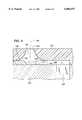
- FIG. 6is a cross-sectional view, similar to FIG. 2, but showing another alternative embodiment of the present invention.
- FIG. 7is a cross-sectional view, similar to FIG. 2, but showing another preferred embodiment of the present invention.
- FIG. 8is a cross-sectional view, similar to FIG. 2, but showing another embodiment of the present invention.
- FIG. 1depicts an ink jet pen 10 that incorporates a printhead 12 that is configured and arranged for carrying out the present invention.
- a preferred embodiment of the pen 10includes a pen body 14 that defines an internal reservoir for holding a supply of ink. The ink is ejected from the printhead through a plurality of orifices 16 that extend through the exterior of the printhead 12, as shown in FIG. 1.
- FIG. 2is a greatly enlarged cross-sectional view taken through the printhead and through one of the orifices 16.
- the orifice 16is formed in the outer surface 20 of an orifice member or plate 22.
- the orifice plate 22is attached to a substrate 23.
- the substratecomprises a silicon base 24 and a support layer 25 as described more fully below.
- the orifice plate 22, silicone base 24 and support layer 25comprise a chamber member 27.
- the orifice 16is an opening through the plate 22 of an ink chamber 26 that is formed in the orifice plate 22.
- the diameter of the of the orifice 16may be, for example, about 12 to 16 ⁇ m.
- the chamber 26is shown with an upwardly tapered sidewall 28, thereby defining a generally frustrum-shaped chamber, the bottom of which is substantially defined by the upper surface 30 of the substrate 23.
- the orifice plate 22may be formed using a spin-on or laminated polymer.
- the polymermay be purchased commercially under the trademark CYCLOTENE from Dow Chemical, having a thickness of about 10 to 30 ⁇ m. Any other suitable polymer film may be used, such as polyamide, polymethylmethacrylate, polycarbonate, polyester, polyamide, polyethylene-terephthalate or mixtures thereof.
- the orificemay be formed of a gold-plated nickel member manufactured by electrodeposition techniques.
- the upper surface 32 of the silicon base 24is coated with a support layer 25.
- the support layer 25is formed of silicon dioxide, silicon nitride, silicon carbide, tantalum, polysilicon glass or other functionally equivalent material having different etchant sensitivity than the silicon base 24 of the substrate.
- two ink inlets 42are formed to extend through that layer.
- the upper surface 30 of the support layeris patterned and etched to form the inlets 42, before the orifice plate 22 is attached to the substrate 23, and before a channel 40 is etched into the base 24 as described below.
- a thin-film resistor 34is attached to the upper surface 30 of the substrate.
- the resistoris applied after the inlets 42 are formed, but before the orifice plate 22 is attached to the substrate.
- the resistormay be about 12 ⁇ m long by 12 ⁇ m wide (see FIG. 3).
- a very thin (about 0.5 ⁇ m) passivation layer(not shown) is deposited on the resistor to provide protection from damage by cavitation.
- the overall thickness of the support layer, resistor and passivation layeris about 3 ⁇ m.
- the resistor 34is located immediately adjacent to the inlets 42.
- the resistor 34acts as an ohmic heater when selectively energized by a voltage pulse applied to it.
- each resistor 34contacts at opposing sides of the resistor a conductive trace 36.
- the tracesare deposited on the substrate 23 and are electrically connected to the printer microprocessor for conducting the voltage pulses.
- the conductive traces 36appear in FIG. 3.
- the preferred orifice plate 22is laid over the substrate 23 on the upper surface 30 of the support layer 25.
- the plate 22can be laminated, spun on while in liquid form, grown or deposited in place, or plated in place. The plate adheres to the support layer 25.
- the resistor 34is selectively heated or driven by the microprocessor to generate a vapor bubble 50 (shown in dashed lines in FIG. 2) within the ink-filled chamber 26. Ink ejected from the chamber as a consequence of the expanding bubble 50 travels through the central axis 52 of the orifice.
- An ink channel 40is formed in the base 24 of the substrate 23 to be in fluid communication with the inlets 42.
- the channel 40is etched by anisotropic etching from the lower side of the base 24 up to the underside 29 of the support layer 25.
- ink present in the reservoir of the pen body 14flows by capillary force through each channel 40 and through the inlets 42 to fill the ink chamber 26.
- the channel 40has a significantly larger volume than the ink inlets 42.
- the channelmay be oriented to provide ink to more than one chamber 26.
- Each of the channelsmay extend to connect with an even larger slot (not shown) cut in the substrate base 24 and in direct fluid communication with the pen reservoir.
- the base 24 of the substrateis bonded to the pen body surface, which surface defines the boundary of the channel.
- the inlets 42are located to be immediately adjacent to the resistor 34 and are sized so that, upon firing, the expanded bubble 50 occludes the inlets 42 and prevents ink within the chamber 26 from being blown back into the channel 40.
- the inlets 42are contiguous with (not significantly spaced from) the chamber 26 and are located so that the junction of the inlet 42 and the chamber 26 is very near the resistor 34.
- each inletis spaced from the resistor by no more than 25% of the resistor member length.
- the elimination of the liquid pathwayis best achieved when the bubble 50 completely penetrates the inlets 42 and expands slightly into the volume of the channel 40, as shown by the dashed lines in FIG. 2.
- the total area of the inletsshould be less than about 120% of the area of the resistor.
- Occlusion of the inlet(s) by the expanded vapor bubblemay occur with printhead configurations unlike those just described in connection with a preferred embodiment.
- the distance of the inlet from the resistor, or heating member, and the cross-sectional area of the inletmay be greater or less than that specified above, depending upon certain variables.
- variablesinclude ink viscosity and related thermodynamic properties, resistor heat energy per unit of resistor area, and surface energy of the material along which the ink and vapor move.
- the thickness of the passivation layersrelative to that of the resistor and the associated thermal conductivity of those components.
- the resistor energy densityis about 4 nJ/ ⁇ m 2
- the viscosity of the inkis about 3 cp, having a boiling point of about 100° C.
- the flow of ink through the inlets 42generally follows a somewhat linear path indicated as arrow 54 in that figure.
- the flow path 54is generally away from the resistor 34 and toward the orifice 16. More particularly, the flow path 54 is generally parallel to the central axis 52 of the orifice 16.
- FIGS. 4 and 5The embodiment depicted in FIGS. 4 and 5 is much like that depicted in FIGS. 2 and 3 inasmuch as this latter embodiment includes an orifice plate 122 that is attached to a substrate 123 that comprises a base 124 and support layer 125 as described with respect to similarly named components in the FIG. 2 embodiment.
- FIG. 6depicts an orifice plate 222 in which is formed a chamber 226 and orifice 216 in a manner as described with respect to the earlier embodiments.
- the substratecomprises a silicon base 224 and a relatively thick (for example, 8 ⁇ m) adhesive polymer layer 225 for securing the orifice plate 222 to the silicon base 224.
- the ink channel 240comprises an elongated slot etched into the silicon base 224 to a location very near (for example, 1 ⁇ m) one edge of the resistor 234. Accordingly, the inlet 242 is defined by the gap between the lower periphery 243 of the chamber 226 and the edge 229 defined by the upper surface 232 of the base and the end wall 231 of the etched channel 240. It will be appreciated that in plan view the inlet 242 in this embodiment is generally crescent shaped.
- the cross-sectional area of the just-described gap or inletis sized to conform to the preferred areal limitations mentioned above.
- the inlet 242is also spaced very near the resistor 234. Consequently, the expansion of the bubble 250 upon firing causes the bubble to pass through the inlet 242 and occlude that inlet as ink is being ejected from the chamber 226 along central axis 252 of the associated orifice 216.
- the flow path 254 of the refill ink into the chamberis, as in prior embodiments, directed away from the resistor and toward the orifice. In this embodiment, however, the flow path 254 of ink in the inlet is not quite parallel to the orifice central axis 252. Instead, the flow path 254 defines an acute angle (shown in FIG. 6 by reference numeral 253) with the central axis 252. In this arrangement, there remains enough flow momentum of the refill ink to lift the final collapse point "X" of the bubble from the surface of the resistor, thus providing the attendant protection from cavitation damage.
- FIG. 7depicts a cross-section of another alternative embodiment of the present invention, whereby a silicon base 324 is etched in a manner similar to the embodiment of FIG. 6 to define a slotted channel 340 that terminates very near the resistor 334.
- the orifice plate 322comprises a KAPTON tape or similar polymer tape as described earlier, which, prior to being bonded to the base, is laser-ablated from its underside 333 to define the chamber 326 as described next.
- the chamber 326is formed to extend completely through the orifice plate 322 as shown in FIG. 7. Moreover, the laser radiation is masked and controlled so that the underside of the chamber is removed by an amount such that it is spaced from the resistor 334. As a result, the angular extension 341 of the channel and the chamber 326 define between them a tubular projection 345. It will be appreciated, therefore, that the space between this projection 345 and the resistor 334 defines the inlet through which refill ink flows into the chamber 326 from the channel extension 341. Moreover, the gap or inlet is occluded when the vapor bubble 350 generated by the heated resistor 334 expands to separate the liquid pathway between the angular channel 341 and the chamber 326.
- FIG. 8depicts a cross-section of an alternative embodiment whereby the ink inlet 442 arises as a result of the positioning of an orifice plate 422 so that the central axis 452 of the orifice 416 is offset relative to the center of the resistor 434.
- a silicon base 424carries a thin-film resistor 434 that is connected, as described earlier, via conductive traces to the printer microprocessor for carrying voltage pulses that heat the resistor to expand a vapor bubble 450.
- a barrier layer 425is formed on the base 424.
- the barriercomprises a photosensitive polymer that is shaped by a photolithographic process to define on three sides of the resistor 434 a portion of the ink chamber 426. Where the barrier layer 425 is removed, there is defined an ink channel 440 for conveying ink from a distant slot 445 that is cut through the base 424 and is in fluid communication with the ink stored in the pen reservoir.
- the orifice plate 422which is preferably formed of electrodeposited nickel and is gold-plated, defines a smoothly tapered sidewall portion 428.
- the orifice plate 422is laid over the resistors 434 so that the central axis 452 of the orifice 416 nearest the resistor 434 is displaced from the center of the resistor 434 to define the gap 442 as mentioned earlier.
- the gap, or inlet 442is occluded by the expanding bubble 450 so that, as in other embodiments, the expanding bubble acts as a valve to temporarily close the inlet 442 for the advantages mentioned earlier.
Landscapes
- Engineering & Computer Science (AREA)
- Manufacturing & Machinery (AREA)
- Physics & Mathematics (AREA)
- Thermal Sciences (AREA)
- Geometry (AREA)
- Optics & Photonics (AREA)
- Particle Formation And Scattering Control In Inkjet Printers (AREA)
Abstract
Description
Claims (14)
Priority Applications (1)
| Application Number | Priority Date | Filing Date | Title |
|---|---|---|---|
| US08/692,905US6003977A (en) | 1996-02-07 | 1996-07-30 | Bubble valving for ink-jet printheads |
Applications Claiming Priority (2)
| Application Number | Priority Date | Filing Date | Title |
|---|---|---|---|
| US08/597,746US6000787A (en) | 1996-02-07 | 1996-02-07 | Solid state ink jet print head |
| US08/692,905US6003977A (en) | 1996-02-07 | 1996-07-30 | Bubble valving for ink-jet printheads |
Related Parent Applications (1)
| Application Number | Title | Priority Date | Filing Date |
|---|---|---|---|
| US08/597,746Continuation-In-PartUS6000787A (en) | 1996-02-07 | 1996-02-07 | Solid state ink jet print head |
Publications (1)
| Publication Number | Publication Date |
|---|---|
| US6003977Atrue US6003977A (en) | 1999-12-21 |
Family
ID=46202951
Family Applications (1)
| Application Number | Title | Priority Date | Filing Date |
|---|---|---|---|
| US08/692,905Expired - LifetimeUS6003977A (en) | 1996-02-07 | 1996-07-30 | Bubble valving for ink-jet printheads |
Country Status (1)
| Country | Link |
|---|---|
| US (1) | US6003977A (en) |
Cited By (65)
| Publication number | Priority date | Publication date | Assignee | Title |
|---|---|---|---|---|
| US6062681A (en)* | 1998-07-14 | 2000-05-16 | Hewlett-Packard Company | Bubble valve and bubble valve-based pressure regulator |
| US6158846A (en)* | 1997-08-08 | 2000-12-12 | Hewlett-Packard Co. | Forming refill for monolithic inkjet printhead |
| US6280021B1 (en)* | 1998-06-15 | 2001-08-28 | Industrial Technology Research Institute | Structure of ink slot on ink-jet printhead chip |
| WO2001078986A1 (en)* | 2000-04-18 | 2001-10-25 | Silverbrook Research Pty Ltd | Ink jet ejector |
| US6364466B1 (en)* | 2000-11-30 | 2002-04-02 | Hewlett-Packard Company | Particle tolerant ink-feed channel structure for fully integrated inkjet printhead |
| EP1186414A3 (en)* | 2000-09-06 | 2002-08-07 | Canon Kabushiki Kaisha | Ink jet recording head and method of manufacturing the same |
| EP1275505A3 (en)* | 2001-07-11 | 2003-03-05 | Canon Kabushiki Kaisha | Liquid ejection head |
| US20030189622A1 (en)* | 2001-10-31 | 2003-10-09 | Giere Matthew D. | Printhead having a thin film membrane with a floating section |
| US6659593B1 (en) | 2000-04-18 | 2003-12-09 | Silverbrook Research Pty Ltd | Ink jet ejector |
| US20040027423A1 (en)* | 2002-08-19 | 2004-02-12 | Kia Silverbrook | Liquid ejection device |
| US20040085402A1 (en)* | 1997-07-15 | 2004-05-06 | Kia Silverbrook | Micro-electromechanical valve assembly |
| US20040104198A1 (en)* | 2001-10-31 | 2004-06-03 | Chien-Hua Chen | Fluid ejection device with a composite substrate |
| US6761433B2 (en)* | 2000-07-11 | 2004-07-13 | Samsung Electronics Co., Ltd. | Bubble-jet type ink-jet printhead |
| US20040155930A1 (en)* | 2003-02-08 | 2004-08-12 | Chang-Ho Cho | Ink-jet printhead and method for manufacturing the same |
| US20050134660A1 (en)* | 2002-08-19 | 2005-06-23 | Kia Silverbrook | Ink supply system for multiple ink printing |
| US20050157082A1 (en)* | 1997-07-15 | 2005-07-21 | Silverbrook Research Pty Ltd | Inkjet nozzle with individual ink feed channels etched from both sides of wafer |
| US20050285904A1 (en)* | 2004-06-02 | 2005-12-29 | Canon Kabushiki Kaisha | Liquid ejecting head and liquid ejecting apparatus usable therewith |
| US20060044372A1 (en)* | 2002-11-23 | 2006-03-02 | Silverbrook Research Pty Ltd | Thermal ink jet with chemical vapor deposited nozzle plate |
| US20060044356A1 (en)* | 2002-11-23 | 2006-03-02 | Silverbrook Research Pty Ltd | Thermal ink jet printhead with cavitation gap |
| US20060125892A1 (en)* | 2004-12-10 | 2006-06-15 | Lexmark International, Inc. | Inkjet printhead with bubble handling properties |
| US20060221137A1 (en)* | 2005-04-04 | 2006-10-05 | Silverbrook Research Pty Ltd | Inkjet printhead with low thermal product layer |
| US20060221135A1 (en)* | 2005-04-04 | 2006-10-05 | Silverbrook Research Pty Ltd | Self passivating transition metal nitride printhead heaters |
| US20060221134A1 (en)* | 2005-04-04 | 2006-10-05 | Silverbrook Research Pty Ltd | Printhead heaters with a nanocrystalline composite structure |
| US20060221136A1 (en)* | 2005-04-04 | 2006-10-05 | Silverbrook Research Pty Ltd | Inkjet printhead heater elements with thin or non-existent coatings |
| US20070046733A1 (en)* | 2005-09-01 | 2007-03-01 | Canon Kabushiki Kaisha | Liquid discharge head |
| US20070080989A1 (en)* | 2005-10-11 | 2007-04-12 | Silverbrook Research Pty Ltd | Intercolour surface barriers in multi colour inkjet printhead |
| US20070081044A1 (en)* | 2005-10-11 | 2007-04-12 | Silverbrook Research Pty Ltd | Inkjet printhead with multiple ink inlet flow paths |
| US20070081028A1 (en)* | 2005-10-11 | 2007-04-12 | Silverbrook Research Pty Ltd | Reduced stiction printhead surface |
| US20070081032A1 (en)* | 2005-10-11 | 2007-04-12 | Silverbrook Research Pty Ltd. | Low loss electrode connection for inkjet printhead |
| US20070081045A1 (en)* | 2005-10-11 | 2007-04-12 | Silverbrook Research Pty Ltd | Inkjet printhead with multi-nozzle chambers |
| US20070081041A1 (en)* | 2005-10-11 | 2007-04-12 | Silverbrook Research Pty Ltd | Inkjet printhead with inlet priming feature |
| US20070081036A1 (en)* | 2005-10-11 | 2007-04-12 | Silverbrook Research Pty Ltd | Inkjet printhead with multiple chambers and multiple nozzles for each drive circuit |
| US20070081058A1 (en)* | 2005-10-11 | 2007-04-12 | Silverbrook Research Pty Ltd | Printhead with inlet filter for ink chamber |
| US20070081040A1 (en)* | 2005-10-11 | 2007-04-12 | Silverbrook Research Pty Ltd | Printhead with multiple actuators in each chamber |
| US20070081049A1 (en)* | 2005-10-11 | 2007-04-12 | Silverbrook Research Pty Ltd | Printhead with side entry ink chamber |
| US20070081033A1 (en)* | 2005-10-11 | 2007-04-12 | Silverbrook Research Pty Ltd | High density thermal ink jet printhead |
| US20070081043A1 (en)* | 2005-10-11 | 2007-04-12 | Silverbrook Research Pty Ltd | Inkjet printhead with bubble trap |
| US20070081039A1 (en)* | 2005-10-11 | 2007-04-12 | Silverbrook Research Pty Ltd | Printhead with ink feed to chamber via adjacent chamber |
| WO2007041744A1 (en)* | 2005-10-10 | 2007-04-19 | Silverbrook Research Pty Ltd | Low loss electrode connection for inkjet printhead |
| US20070145636A1 (en)* | 2005-12-28 | 2007-06-28 | Johns Gina M | Ink tank incorporating lens for ink level sensing |
| US20070268335A1 (en)* | 2005-10-11 | 2007-11-22 | Silverbrook Research Pty Ltd | Inkjet printhead with opposing actuator electrode polarities |
| US20080024574A1 (en)* | 2006-07-28 | 2008-01-31 | Jeremy Harlan Donaldson | Fluid ejection devices and methods of fabrication |
| US20090033720A1 (en)* | 2002-11-23 | 2009-02-05 | Silverbrook Research Pty Ltd | Printhead having efficient heater elements for small drop ejection |
| US20090040278A1 (en)* | 2002-11-23 | 2009-02-12 | Silverbrook Research Pty Ltd | Printhead having low energy heater elements |
| US20090058950A1 (en)* | 2002-11-23 | 2009-03-05 | Silverbrook Research Pty Ltd | Thermal ink jet printhead with heater element positioned for minimized ink drop momentum |
| US20090185007A1 (en)* | 1997-07-15 | 2009-07-23 | Silverbrook Research Pty Ltd | Printhead with backflow resistant nozzle chambers |
| WO2010126520A1 (en)* | 2009-04-30 | 2010-11-04 | Hewlett-Packard Development Company, L.P. | Printhead for generating ink drops with reduced tails |
| US7845765B2 (en) | 2005-10-11 | 2010-12-07 | Silverbrook Research Pty Ltd | Inkjet printers with elongate chambers, nozzles and heaters |
| US20110049092A1 (en)* | 2009-08-26 | 2011-03-03 | Alfred I-Tsung Pan | Inkjet printhead bridge beam fabrication method |
| US20110122183A1 (en)* | 2005-04-04 | 2011-05-26 | Silverbrook Research Pty Ltd | Printhead incorporating pressure pulse diffusing structures between ink chambers supplied by same ink inlet |
| US7950777B2 (en) | 1997-07-15 | 2011-05-31 | Silverbrook Research Pty Ltd | Ejection nozzle assembly |
| US20110205303A1 (en)* | 2008-10-14 | 2011-08-25 | Hewlett-Packard Development Company, L.P. | Fluid ejector structure |
| US8020970B2 (en) | 1997-07-15 | 2011-09-20 | Silverbrook Research Pty Ltd | Printhead nozzle arrangements with magnetic paddle actuators |
| US20110227987A1 (en)* | 2008-10-30 | 2011-09-22 | Alfred I-Tsung Pan | Thermal inkjet printhead feed transition chamber and method of cooling using same |
| US8025366B2 (en) | 1997-07-15 | 2011-09-27 | Silverbrook Research Pty Ltd | Inkjet printhead with nozzle layer defining etchant holes |
| US8029101B2 (en) | 1997-07-15 | 2011-10-04 | Silverbrook Research Pty Ltd | Ink ejection mechanism with thermal actuator coil |
| US8029102B2 (en) | 1997-07-15 | 2011-10-04 | Silverbrook Research Pty Ltd | Printhead having relatively dimensioned ejection ports and arms |
| US8061812B2 (en) | 1997-07-15 | 2011-11-22 | Silverbrook Research Pty Ltd | Ejection nozzle arrangement having dynamic and static structures |
| US8075104B2 (en) | 1997-07-15 | 2011-12-13 | Sliverbrook Research Pty Ltd | Printhead nozzle having heater of higher resistance than contacts |
| US8083326B2 (en) | 1997-07-15 | 2011-12-27 | Silverbrook Research Pty Ltd | Nozzle arrangement with an actuator having iris vanes |
| US8113629B2 (en) | 1997-07-15 | 2012-02-14 | Silverbrook Research Pty Ltd. | Inkjet printhead integrated circuit incorporating fulcrum assisted ink ejection actuator |
| US8123336B2 (en) | 1997-07-15 | 2012-02-28 | Silverbrook Research Pty Ltd | Printhead micro-electromechanical nozzle arrangement with motion-transmitting structure |
| CN102470673A (en)* | 2009-07-31 | 2012-05-23 | 惠普开发有限公司 | Ink jet print head and method employing a central ink feed channel |
| US20160375685A1 (en)* | 2015-06-25 | 2016-12-29 | Canon Kabushiki Kaisha | Liquid ejection head substrate and liquid ejection head |
| CN109228656A (en)* | 2017-07-10 | 2019-01-18 | 精工电子打印科技有限公司 | Channel member, liquid ejecting head and liquid injection apparatus |
Citations (23)
| Publication number | Priority date | Publication date | Assignee | Title |
|---|---|---|---|---|
| US3973106A (en)* | 1974-11-15 | 1976-08-03 | Hewlett-Packard Company | Thin film thermal print head |
| US4463359A (en)* | 1979-04-02 | 1984-07-31 | Canon Kabushiki Kaisha | Droplet generating method and apparatus thereof |
| US4513298A (en)* | 1983-05-25 | 1985-04-23 | Hewlett-Packard Company | Thermal ink jet printhead |
| US4528574A (en)* | 1983-03-28 | 1985-07-09 | Hewlett-Packard Company | Apparatus for reducing erosion due to cavitation in ink jet printers |
| US4683481A (en)* | 1985-12-06 | 1987-07-28 | Hewlett-Packard Company | Thermal ink jet common-slotted ink feed printhead |
| US4794411A (en)* | 1987-10-19 | 1988-12-27 | Hewlett-Packard Company | Thermal ink-jet head structure with orifice offset from resistor |
| US4847630A (en)* | 1987-12-17 | 1989-07-11 | Hewlett-Packard Company | Integrated thermal ink jet printhead and method of manufacture |
| US4882595A (en)* | 1987-10-30 | 1989-11-21 | Hewlett-Packard Company | Hydraulically tuned channel architecture |
| US4894664A (en)* | 1986-04-28 | 1990-01-16 | Hewlett-Packard Company | Monolithic thermal ink jet printhead with integral nozzle and ink feed |
| US4896171A (en)* | 1984-03-31 | 1990-01-23 | Canon Kabushiki Kaisha | Liquid ejection recording head removably mounted on a storage tank |
| US4947193A (en)* | 1989-05-01 | 1990-08-07 | Xerox Corporation | Thermal ink jet printhead with improved heating elements |
| US5016024A (en)* | 1990-01-09 | 1991-05-14 | Hewlett-Packard Company | Integral ink jet print head |
| US5053787A (en)* | 1988-01-27 | 1991-10-01 | Canon Kabushiki Kaisha | Ink jet recording method and head having additional generating means in the liquid chamber |
| US5159353A (en)* | 1991-07-02 | 1992-10-27 | Hewlett-Packard Company | Thermal inkjet printhead structure and method for making the same |
| US5291226A (en)* | 1990-08-16 | 1994-03-01 | Hewlett-Packard Company | Nozzle member including ink flow channels |
| US5305015A (en)* | 1990-08-16 | 1994-04-19 | Hewlett-Packard Company | Laser ablated nozzle member for inkjet printhead |
| US5305018A (en)* | 1990-08-16 | 1994-04-19 | Hewlett-Packard Company | Excimer laser-ablated components for inkjet printhead |
| US5333007A (en)* | 1991-10-17 | 1994-07-26 | Xerox Corporation | Moisture leakage resistant capping surface for ink jet printhead |
| US5389957A (en)* | 1989-09-18 | 1995-02-14 | Canon Kabushiki Kaisha | Ink jet head with contoured outlet surface |
| US5442384A (en)* | 1990-08-16 | 1995-08-15 | Hewlett-Packard Company | Integrated nozzle member and tab circuit for inkjet printhead |
| US5450113A (en)* | 1992-04-02 | 1995-09-12 | Hewlett-Packard Company | Inkjet printhead with improved seal arrangement |
| US5453769A (en)* | 1992-04-02 | 1995-09-26 | Schantz; Christopher A. | Printhead and a method for the manufacture thereof |
| US5463413A (en)* | 1993-06-03 | 1995-10-31 | Hewlett-Packard Company | Internal support for top-shooter thermal ink-jet printhead |
- 1996
- 1996-07-30USUS08/692,905patent/US6003977A/ennot_activeExpired - Lifetime
Patent Citations (24)
| Publication number | Priority date | Publication date | Assignee | Title |
|---|---|---|---|---|
| US3973106A (en)* | 1974-11-15 | 1976-08-03 | Hewlett-Packard Company | Thin film thermal print head |
| US4463359A (en)* | 1979-04-02 | 1984-07-31 | Canon Kabushiki Kaisha | Droplet generating method and apparatus thereof |
| US4528574A (en)* | 1983-03-28 | 1985-07-09 | Hewlett-Packard Company | Apparatus for reducing erosion due to cavitation in ink jet printers |
| US4513298A (en)* | 1983-05-25 | 1985-04-23 | Hewlett-Packard Company | Thermal ink jet printhead |
| US4896171A (en)* | 1984-03-31 | 1990-01-23 | Canon Kabushiki Kaisha | Liquid ejection recording head removably mounted on a storage tank |
| US4683481A (en)* | 1985-12-06 | 1987-07-28 | Hewlett-Packard Company | Thermal ink jet common-slotted ink feed printhead |
| US4894664A (en)* | 1986-04-28 | 1990-01-16 | Hewlett-Packard Company | Monolithic thermal ink jet printhead with integral nozzle and ink feed |
| US4794411A (en)* | 1987-10-19 | 1988-12-27 | Hewlett-Packard Company | Thermal ink-jet head structure with orifice offset from resistor |
| US4882595A (en)* | 1987-10-30 | 1989-11-21 | Hewlett-Packard Company | Hydraulically tuned channel architecture |
| US4847630A (en)* | 1987-12-17 | 1989-07-11 | Hewlett-Packard Company | Integrated thermal ink jet printhead and method of manufacture |
| US5053787A (en)* | 1988-01-27 | 1991-10-01 | Canon Kabushiki Kaisha | Ink jet recording method and head having additional generating means in the liquid chamber |
| US4947193A (en)* | 1989-05-01 | 1990-08-07 | Xerox Corporation | Thermal ink jet printhead with improved heating elements |
| US5389957A (en)* | 1989-09-18 | 1995-02-14 | Canon Kabushiki Kaisha | Ink jet head with contoured outlet surface |
| US5016024A (en)* | 1990-01-09 | 1991-05-14 | Hewlett-Packard Company | Integral ink jet print head |
| US5442384A (en)* | 1990-08-16 | 1995-08-15 | Hewlett-Packard Company | Integrated nozzle member and tab circuit for inkjet printhead |
| US5305015A (en)* | 1990-08-16 | 1994-04-19 | Hewlett-Packard Company | Laser ablated nozzle member for inkjet printhead |
| US5305018A (en)* | 1990-08-16 | 1994-04-19 | Hewlett-Packard Company | Excimer laser-ablated components for inkjet printhead |
| US5291226A (en)* | 1990-08-16 | 1994-03-01 | Hewlett-Packard Company | Nozzle member including ink flow channels |
| US5408738A (en)* | 1990-08-16 | 1995-04-25 | Hewlett-Packard Company | Method of making a nozzle member including ink flow channels |
| US5159353A (en)* | 1991-07-02 | 1992-10-27 | Hewlett-Packard Company | Thermal inkjet printhead structure and method for making the same |
| US5333007A (en)* | 1991-10-17 | 1994-07-26 | Xerox Corporation | Moisture leakage resistant capping surface for ink jet printhead |
| US5450113A (en)* | 1992-04-02 | 1995-09-12 | Hewlett-Packard Company | Inkjet printhead with improved seal arrangement |
| US5453769A (en)* | 1992-04-02 | 1995-09-26 | Schantz; Christopher A. | Printhead and a method for the manufacture thereof |
| US5463413A (en)* | 1993-06-03 | 1995-10-31 | Hewlett-Packard Company | Internal support for top-shooter thermal ink-jet printhead |
Non-Patent Citations (2)
| Title |
|---|
| James P. Shields, "Thermal Inkjet Review, or How Do Dots Get from the Pen to the Page?" in Hewlett-Packard Journal, p. 67 (Aug. 1992). |
| James P. Shields, Thermal Inkjet Review, or How Do Dots Get from the Pen to the Page in Hewlett Packard Journal , p. 67 (Aug. 1992).* |
Cited By (228)
| Publication number | Priority date | Publication date | Assignee | Title |
|---|---|---|---|---|
| US7377621B2 (en) | 1994-01-05 | 2008-05-27 | Silverbrook Research Pty Ltd | Fluid chamber configuration within an inkjet printhead |
| US20060038853A1 (en)* | 1994-01-05 | 2006-02-23 | Silverbrook Research Pty Ltd | Fluid chamber configuration within an inkjet printhead |
| US20070070124A1 (en)* | 1997-07-15 | 2007-03-29 | Silverbrook Research Pty Ltd | Nozzle assembly incorporating a shuttered actuation mechanism |
| US7140719B2 (en) | 1997-07-15 | 2006-11-28 | Silverbrook Research Pty Ltd | Actuator for a micro-electromechanical valve assembly |
| US8083326B2 (en) | 1997-07-15 | 2011-12-27 | Silverbrook Research Pty Ltd | Nozzle arrangement with an actuator having iris vanes |
| US8113629B2 (en) | 1997-07-15 | 2012-02-14 | Silverbrook Research Pty Ltd. | Inkjet printhead integrated circuit incorporating fulcrum assisted ink ejection actuator |
| US8123336B2 (en) | 1997-07-15 | 2012-02-28 | Silverbrook Research Pty Ltd | Printhead micro-electromechanical nozzle arrangement with motion-transmitting structure |
| US7226145B2 (en) | 1997-07-15 | 2007-06-05 | Silverbrook Research Pty Ltd | Micro-electromechanical valve shutter assembly |
| US20100208000A1 (en)* | 1997-07-15 | 2010-08-19 | Silverbrook Research Pty Ltd | Printhead with high drag nozzle chamber inlets |
| US7703890B2 (en)* | 1997-07-15 | 2010-04-27 | Silverbrook Research Pty Ltd. | Printhead with backflow resistant nozzle chambers |
| US8061812B2 (en) | 1997-07-15 | 2011-11-22 | Silverbrook Research Pty Ltd | Ejection nozzle arrangement having dynamic and static structures |
| US8393714B2 (en) | 1997-07-15 | 2013-03-12 | Zamtec Ltd | Printhead with fluid flow control |
| US8029102B2 (en) | 1997-07-15 | 2011-10-04 | Silverbrook Research Pty Ltd | Printhead having relatively dimensioned ejection ports and arms |
| US8029101B2 (en) | 1997-07-15 | 2011-10-04 | Silverbrook Research Pty Ltd | Ink ejection mechanism with thermal actuator coil |
| US20090185007A1 (en)* | 1997-07-15 | 2009-07-23 | Silverbrook Research Pty Ltd | Printhead with backflow resistant nozzle chambers |
| US20040085402A1 (en)* | 1997-07-15 | 2004-05-06 | Kia Silverbrook | Micro-electromechanical valve assembly |
| US8079669B2 (en) | 1997-07-15 | 2011-12-20 | Silverbrook Research Pty Ltd | Printhead with high drag nozzle chamber inlets |
| US7152960B2 (en) | 1997-07-15 | 2006-12-26 | Silverbrook Research Pty Ltd | Micro-electromechanical valve having transformable valve actuator |
| US7661793B2 (en)* | 1997-07-15 | 2010-02-16 | Silverbrook Research Pty Ltd | Inkjet nozzle with individual ink feed channels etched from both sides of wafer |
| US6783217B2 (en)* | 1997-07-15 | 2004-08-31 | Silverbrook Research Pty Ltd | Micro-electromechanical valve assembly |
| US7357488B2 (en) | 1997-07-15 | 2008-04-15 | Silverbrook Research Pty Ltd | Nozzle assembly incorporating a shuttered actuation mechanism |
| US8025366B2 (en) | 1997-07-15 | 2011-09-27 | Silverbrook Research Pty Ltd | Inkjet printhead with nozzle layer defining etchant holes |
| US20040257403A1 (en)* | 1997-07-15 | 2004-12-23 | Silverbrook Research Pty Ltd | Micro-electromechanical valve shutter assembly |
| US20050036001A1 (en)* | 1997-07-15 | 2005-02-17 | Silverbrook Research Pty Ltd | Actuator for a micro-electromechanical valve assembly |
| US20060227184A1 (en)* | 1997-07-15 | 2006-10-12 | Silverbrook Research Pty Ltd | Micro-electromechanical valve having transformable valve actuator |
| US8020970B2 (en) | 1997-07-15 | 2011-09-20 | Silverbrook Research Pty Ltd | Printhead nozzle arrangements with magnetic paddle actuators |
| US8075104B2 (en) | 1997-07-15 | 2011-12-13 | Sliverbrook Research Pty Ltd | Printhead nozzle having heater of higher resistance than contacts |
| US7950777B2 (en) | 1997-07-15 | 2011-05-31 | Silverbrook Research Pty Ltd | Ejection nozzle assembly |
| US20050157082A1 (en)* | 1997-07-15 | 2005-07-21 | Silverbrook Research Pty Ltd | Inkjet nozzle with individual ink feed channels etched from both sides of wafer |
| US6158846A (en)* | 1997-08-08 | 2000-12-12 | Hewlett-Packard Co. | Forming refill for monolithic inkjet printhead |
| US6280021B1 (en)* | 1998-06-15 | 2001-08-28 | Industrial Technology Research Institute | Structure of ink slot on ink-jet printhead chip |
| US6062681A (en)* | 1998-07-14 | 2000-05-16 | Hewlett-Packard Company | Bubble valve and bubble valve-based pressure regulator |
| US7645028B2 (en) | 2000-04-18 | 2010-01-12 | Silverbrook Research Pty Ltd | Ink ejection nozzle with a paddle having a series of protrusions to reduce outward ink flow |
| US20060028512A1 (en)* | 2000-04-18 | 2006-02-09 | Silverbrook Research Pty Ltd | Inkjet nozzle arrangement with ink flow control |
| US7874640B2 (en) | 2000-04-18 | 2011-01-25 | Silverbrook Research Pty Ltd | Inkjet printhead employing nozzle paddle ink ejecting actuator |
| US6969473B2 (en) | 2000-04-18 | 2005-11-29 | Silverbrook Research Pty Ltd | Manufacturing a liquid ejection device |
| US7581818B2 (en) | 2000-04-18 | 2009-09-01 | Silverbook Research Pty Ltd | Pagewidth inkjet printhead with ink ejection devices having a series of protrusions to facilitate ink ejection |
| US7007859B2 (en)* | 2000-04-18 | 2006-03-07 | Silverbrook Research Pty Ltd | Method of operating a liquid ejection device |
| US7980668B2 (en) | 2000-04-18 | 2011-07-19 | Silverbrook Research Pty Ltd | Ejection arrangement for printhead nozzle |
| US20080239008A1 (en)* | 2000-04-18 | 2008-10-02 | Silverbrook Research Pty Ltd | Pagewidth Inkjet Printhead With Ink Ejection Devices Having A Series Of Protrusions To Facilitate Ink Ejection |
| US20080192090A1 (en)* | 2000-04-18 | 2008-08-14 | Silverbrook Research Pty Ltd | Ink ejection arrangement having cooperating chamber wall edge portions and paddle edge portions |
| US20060187261A1 (en)* | 2000-04-18 | 2006-08-24 | Silverbrook Research Pty Ltd | Fluid chamber configuration within an inkjet printhead |
| US20080186361A1 (en)* | 2000-04-18 | 2008-08-07 | Silverbrook Research Pty Ltd | Ink Ejection Nozzle With A Paddle Having A Series Of Protrusions To Reduce Outward Ink Flow |
| US7387363B2 (en) | 2000-04-18 | 2008-06-17 | Silverbrook Research Pty Ltd | Inkjet nozzle arrangement with ink flow control |
| US7591540B2 (en) | 2000-04-18 | 2009-09-22 | Silverbrook Research Pty Ltd | Ink ejection arrangement having cooperating chamber wall edge portions and paddle edge portions |
| US7370941B2 (en) | 2000-04-18 | 2008-05-13 | Silverbrook Research Pty Ltd | Fluid chamber configuration within an inkjet printhead |
| US7604325B2 (en) | 2000-04-18 | 2009-10-20 | Silverbrook Research Pty Ltd | Inkjet printhead with reciprocating actuator |
| US20090289997A1 (en)* | 2000-04-18 | 2009-11-26 | Silverbrook Research Pty Ltd | Inkjet Printhead Employing Nozzle Paddle Ink Ejecting Actuator |
| US20100002054A1 (en)* | 2000-04-18 | 2010-01-07 | Silverbrook Research Pty Ltd | Ejection arrangement for printhead nozzle |
| US7134608B2 (en) | 2000-04-18 | 2006-11-14 | Silverbrook Research Pty Ltd | Inkjet printhead with reciprocating actuator |
| WO2001078986A1 (en)* | 2000-04-18 | 2001-10-25 | Silverbrook Research Pty Ltd | Ink jet ejector |
| US20100013890A1 (en)* | 2000-04-18 | 2010-01-21 | Silverbrook Research Pty Ltd | Inkjet Printhead With Internal Rim In Ink Chamber |
| US20070013744A1 (en)* | 2000-04-18 | 2007-01-18 | Silverbrook Research Pty Ltd | Bicuspid valved ink ejection arrangement for inkjet printhead |
| US20070024675A1 (en)* | 2000-04-18 | 2007-02-01 | Silverbrook Research Pty Ltd | Inkjet printhead with reciprocating actuator |
| US8069565B2 (en) | 2000-04-18 | 2011-12-06 | Silverbrook Research Pty Ltd | Method of forming a nozzle chamber incorporating an ink ejection paddle and nozzle chamber rim |
| US20040032463A1 (en)* | 2000-04-18 | 2004-02-19 | Kia Silverbrook | Manufacturing a liquid ejection device |
| US7669979B2 (en) | 2000-04-18 | 2010-03-02 | Silverbrook Research Pty Ltd | Inkjet printhead with an ink chamber having a movable circular paddle defining an annular aperture |
| US20040027421A1 (en)* | 2000-04-18 | 2004-02-12 | Kia Silverbrook | Method of operating a liquid ejection device |
| US6659593B1 (en) | 2000-04-18 | 2003-12-09 | Silverbrook Research Pty Ltd | Ink jet ejector |
| US7293856B2 (en) | 2000-04-18 | 2007-11-13 | Silverbrook Research Pty Ltd | Bicuspid valved ink ejection arrangement for inkjet printhead |
| US20060011738A1 (en)* | 2000-04-18 | 2006-01-19 | Silverbrook Research Pty Ltd | Inkjet printhead with reciprocating actuator |
| US20100140216A1 (en)* | 2000-04-18 | 2010-06-10 | Silverbrook Research Pty Ltd | Method Of Forming A Nozzle Chamber Incorporating An Ink Ejection Paddle And Nozzle Chamber Rim |
| US8226214B2 (en) | 2000-04-18 | 2012-07-24 | Zamtec Limited | Inkjet printhead with internal rim in ink chamber |
| US6478406B1 (en) | 2000-04-18 | 2002-11-12 | Silverbrook Research Pty Ltd | Ink jet ejector |
| US6761433B2 (en)* | 2000-07-11 | 2004-07-13 | Samsung Electronics Co., Ltd. | Bubble-jet type ink-jet printhead |
| EP1186414A3 (en)* | 2000-09-06 | 2002-08-07 | Canon Kabushiki Kaisha | Ink jet recording head and method of manufacturing the same |
| US6652079B2 (en) | 2000-09-06 | 2003-11-25 | Canon Kabushiki Kaisha | Ink jet recording head with extended electrothermal conversion element life and method of manufacturing the same |
| US6364466B1 (en)* | 2000-11-30 | 2002-04-02 | Hewlett-Packard Company | Particle tolerant ink-feed channel structure for fully integrated inkjet printhead |
| US20060125877A1 (en)* | 2001-07-11 | 2006-06-15 | Canon Kabushiki Kaisha | Liquid ejection head |
| EP1275505A3 (en)* | 2001-07-11 | 2003-03-05 | Canon Kabushiki Kaisha | Liquid ejection head |
| US7384130B2 (en) | 2001-07-11 | 2008-06-10 | Canon Kabushiki Kaisha | Liquid ejection head |
| US7036909B2 (en) | 2001-07-11 | 2006-05-02 | Canon Kabushiki Kaisha | Liquid ejection head |
| US6974548B2 (en) | 2001-10-31 | 2005-12-13 | Hewlett-Packard Development Company, L.P. | Printhead having a thin film membrane with a floating section |
| US20030189622A1 (en)* | 2001-10-31 | 2003-10-09 | Giere Matthew D. | Printhead having a thin film membrane with a floating section |
| EP1308283A3 (en)* | 2001-10-31 | 2003-10-15 | Hewlett-Packard Company | Printhead having a thin film membrane with a floating section |
| US20040104198A1 (en)* | 2001-10-31 | 2004-06-03 | Chien-Hua Chen | Fluid ejection device with a composite substrate |
| US20040027423A1 (en)* | 2002-08-19 | 2004-02-12 | Kia Silverbrook | Liquid ejection device |
| US20050134660A1 (en)* | 2002-08-19 | 2005-06-23 | Kia Silverbrook | Ink supply system for multiple ink printing |
| US20050140739A1 (en)* | 2002-08-19 | 2005-06-30 | Kia Silverbrook | Ink supply system with integrated data and power supply |
| US20050140740A1 (en)* | 2002-08-19 | 2005-06-30 | Kia Silverbrook | Ink supply system for a portable printer |
| US20050140738A1 (en)* | 2002-08-19 | 2005-06-30 | Kia Silverbrook | Ink supply system with breather openings |
| US7287839B2 (en) | 2002-08-19 | 2007-10-30 | Silverbrook Research Pty Ltd | Inkjet printhead having bicuspid valved ink ejection arrangement |
| US7140722B2 (en) | 2002-08-19 | 2006-11-28 | Silverbrook Research Pty Ltd | Non-planar ink ejection arrangement for inkjet printhead |
| US6827425B2 (en)* | 2002-08-19 | 2004-12-07 | Silverbrook Research Pty Ltd | Liquid ejection device |
| US7097283B2 (en) | 2002-08-19 | 2006-08-29 | Silverbrook Research Pty Ltd | Inkjet printhead having non-planar ink ejector |
| US20090058950A1 (en)* | 2002-11-23 | 2009-03-05 | Silverbrook Research Pty Ltd | Thermal ink jet printhead with heater element positioned for minimized ink drop momentum |
| US7465034B2 (en)* | 2002-11-23 | 2008-12-16 | Silverbrook Research Pty Ltd | Thermal ink jet printhead with cavitation gap |
| US20100149278A1 (en)* | 2002-11-23 | 2010-06-17 | Silverbrook Research Pty Ltd | Printhead Having Low Energy Heating Circuitry |
| US20100149276A1 (en)* | 2002-11-23 | 2010-06-17 | Silverbrook Research Pty Ltd | Nozzle chambers having suspended heater elements |
| US7587822B2 (en) | 2002-11-23 | 2009-09-15 | Silverbrook Research Pty Ltd | Method of producing high nozzle density printhead in-situ |
| US20100118093A1 (en)* | 2002-11-23 | 2010-05-13 | Silverbrook Research Pty Ltd | Printhead system with substrate channel supporting printhead and ink hose |
| US8006384B2 (en)* | 2002-11-23 | 2011-08-30 | Silverbrook Research Pty Ltd | Method of producing pagewidth inkjet printhead |
| US20110197443A1 (en)* | 2002-11-23 | 2011-08-18 | Silverbrook Research Pty Ltd | Inkjet printhead production method |
| US20080088676A1 (en)* | 2002-11-23 | 2008-04-17 | Silverbrook Research Pty Ltd | Ink Jet Printhead With Suspended Heater Element |
| US7832844B2 (en) | 2002-11-23 | 2010-11-16 | Silverbrook Research Pty Ltd | Printhead having efficient heater elements for small drop ejection |
| US20100064517A1 (en)* | 2002-11-23 | 2010-03-18 | Silverbrook Research Pty Ltd | Method Of Producing Pagewidth Inkjet Printhead |
| US7669972B2 (en) | 2002-11-23 | 2010-03-02 | Silverbrook Research Pty Ltd | Printhead having suspended heater elements |
| US7587823B2 (en) | 2002-11-23 | 2009-09-15 | Silverbrook Research Pty Ltd | Method of producing pagewidth printhead structures in-situ |
| US20070144002A1 (en)* | 2002-11-23 | 2007-06-28 | Silverbrook Research Pty Ltd | Method of producing high nozzle density printhead in-situ |
| US7669980B2 (en) | 2002-11-23 | 2010-03-02 | Silverbrook Research Pty Ltd | Printhead having low energy heater elements |
| US7984971B2 (en) | 2002-11-23 | 2011-07-26 | Silverbrook Research Pty Ltd | Printhead system with substrate channel supporting printhead and ink hose |
| US20070144003A1 (en)* | 2002-11-23 | 2007-06-28 | Silverbrook Research Pty Ltd | Method of producing energy efficient printhead in-situ |
| US7322686B2 (en)* | 2002-11-23 | 2008-01-29 | Silverbrook Research Pty Ltd | Thermal ink jet with chemical vapor deposited nozzle plate |
| US20090244196A1 (en)* | 2002-11-23 | 2009-10-01 | Silverbrook Research Pty Ltd | Ink Jet Printhead with Inner and Outer Heating Loops |
| US20070144004A1 (en)* | 2002-11-23 | 2007-06-28 | Silverbrook Research Pty Ltd | Method of producing pagewidth printhead structures in-situ |
| US20060044356A1 (en)* | 2002-11-23 | 2006-03-02 | Silverbrook Research Pty Ltd | Thermal ink jet printhead with cavitation gap |
| US7562966B2 (en) | 2002-11-23 | 2009-07-21 | Silverbrook Research Pty Ltd | Ink jet printhead with suspended heater element |
| US7950776B2 (en) | 2002-11-23 | 2011-05-31 | Silverbrook Research Pty Ltd | Nozzle chambers having suspended heater elements |
| US7631427B2 (en) | 2002-11-23 | 2009-12-15 | Silverbrook Research Pty Ltd | Method of producing energy efficient printhead in-situ |
| US20090300915A1 (en)* | 2002-11-23 | 2009-12-10 | Silverbrook Research Pty Ltd | Method Of Producing An Inkjet Printhead |
| US20090300916A1 (en)* | 2002-11-23 | 2009-12-10 | Silverbrook Research Pty Ltd | Inkjet Printhead Production Method |
| US20090033720A1 (en)* | 2002-11-23 | 2009-02-05 | Silverbrook Research Pty Ltd | Printhead having efficient heater elements for small drop ejection |
| US20090040278A1 (en)* | 2002-11-23 | 2009-02-12 | Silverbrook Research Pty Ltd | Printhead having low energy heater elements |
| US20090160911A1 (en)* | 2002-11-23 | 2009-06-25 | Silverbrook Research Pty Ltd | Printhead having overlayed heater and non-heater elements |
| US20060044372A1 (en)* | 2002-11-23 | 2006-03-02 | Silverbrook Research Pty Ltd | Thermal ink jet with chemical vapor deposited nozzle plate |
| US7946026B2 (en) | 2002-11-23 | 2011-05-24 | Silverbrook Research Pty Ltd | Inkjet printhead production method |
| US20090073238A1 (en)* | 2002-11-23 | 2009-03-19 | Silverbrook Research Pty Ltd | Printhead having suspended heater elements |
| US7922294B2 (en) | 2002-11-23 | 2011-04-12 | Silverbrook Research Pty Ltd | Ink jet printhead with inner and outer heating loops |
| EP1447223A3 (en)* | 2003-02-08 | 2004-09-08 | Samsung Electronics Co., Ltd. | Ink-jet printhead and method for manufacturing the same |
| US20040155930A1 (en)* | 2003-02-08 | 2004-08-12 | Chang-Ho Cho | Ink-jet printhead and method for manufacturing the same |
| US7367656B2 (en) | 2003-02-08 | 2008-05-06 | Samsung Electronics Co., Ltd. | Ink-jet printhead and method for manufacturing the same |
| US20090295874A1 (en)* | 2004-06-02 | 2009-12-03 | Canon Kabushiki Kaisha | Liquid ejecting head and liquid ejecting apparatus usable therewith |
| US8109610B2 (en) | 2004-06-02 | 2012-02-07 | Canon Kabushiki Kaisha | Liquid ejecting head and liquid ejecting apparatus usable therewith |
| US7591538B2 (en) | 2004-06-02 | 2009-09-22 | Canon Kabushiki Kaisha | Liquid ejecting head and liquid ejecting apparatus usable therewith |
| US20050285904A1 (en)* | 2004-06-02 | 2005-12-29 | Canon Kabushiki Kaisha | Liquid ejecting head and liquid ejecting apparatus usable therewith |
| US7201476B2 (en) | 2004-12-10 | 2007-04-10 | Lexmark International, Inc. | Inkjet printhead with bubble handling properties |
| US20060125892A1 (en)* | 2004-12-10 | 2006-06-15 | Lexmark International, Inc. | Inkjet printhead with bubble handling properties |
| US7980674B2 (en) | 2005-04-04 | 2011-07-19 | Silverbrook Research Pty Ltd | Printhead incorporating pressure pulse diffusing structures between ink chambers supplied by same ink inlet |
| US20060221136A1 (en)* | 2005-04-04 | 2006-10-05 | Silverbrook Research Pty Ltd | Inkjet printhead heater elements with thin or non-existent coatings |
| US7874638B2 (en) | 2005-04-04 | 2011-01-25 | Silverbrook Research Pty Ltd | Printhead assembly with channelled printhead modules |
| US7377623B2 (en)* | 2005-04-04 | 2008-05-27 | Silverbrook Research Pty Ltd | Printhead heaters with a nanocrystalline composite structure |
| US7857427B2 (en)* | 2005-04-04 | 2010-12-28 | Silverbrook Research Pty Ltd | Inkjet printhead having MEMS sensors for directionally heated ink ejection |
| US8622521B2 (en) | 2005-04-04 | 2014-01-07 | Zamtec Ltd | Inkjet printhead having titanium aluminium nitride heater elements |
| US8356885B2 (en)* | 2005-04-04 | 2013-01-22 | Zamtec Ltd | MEMS fluid sensor |
| US7891764B2 (en) | 2005-04-04 | 2011-02-22 | Silverbrook Research Pty Ltd | Printhead assembly with sandwiched power supply arrangement |
| US20090002421A1 (en)* | 2005-04-04 | 2009-01-01 | Silverbrook Research Pty Ltd | Inkjet printhead comprising bonded heater element and dielectric layer with low thermal product |
| US20110122183A1 (en)* | 2005-04-04 | 2011-05-26 | Silverbrook Research Pty Ltd | Printhead incorporating pressure pulse diffusing structures between ink chambers supplied by same ink inlet |
| US20080316256A1 (en)* | 2005-04-04 | 2008-12-25 | Silverbrook Research Pty Ltd | Printhead assembly with sandwiched power supply arrangement |
| US20080303872A1 (en)* | 2005-04-04 | 2008-12-11 | Silverbrook Research Pty Ltd | Nozzle arrangement for an inkjet printer configured to minimize thermal losses |
| US20060221134A1 (en)* | 2005-04-04 | 2006-10-05 | Silverbrook Research Pty Ltd | Printhead heaters with a nanocrystalline composite structure |
| US20060221135A1 (en)* | 2005-04-04 | 2006-10-05 | Silverbrook Research Pty Ltd | Self passivating transition metal nitride printhead heaters |
| US7448729B2 (en)* | 2005-04-04 | 2008-11-11 | Silverbrook Research Pty Ltd | Inkjet printhead heater elements with thin or non-existent coatings |
| US20060221137A1 (en)* | 2005-04-04 | 2006-10-05 | Silverbrook Research Pty Ltd | Inkjet printhead with low thermal product layer |
| US7431431B2 (en)* | 2005-04-04 | 2008-10-07 | Silverbrook Research Pty Ltd | Self passivating transition metal nitride printhead heaters |
| US20080239009A1 (en)* | 2005-04-04 | 2008-10-02 | Silverbrook Research Pty Ltd | Inkjet printhead having mems sensors for directionally heated ink ejection |
| US7419249B2 (en)* | 2005-04-04 | 2008-09-02 | Silverbrook Research Pty Ltd | Inkjet printhead with low thermal product layer |
| US7677702B2 (en) | 2005-04-04 | 2010-03-16 | Silverbrook Research Pty Ltd | Inkjet printhead comprising bonded heater element and dielectric layer with low thermal product |
| US20100149279A1 (en)* | 2005-04-04 | 2010-06-17 | Silverbrook Research Pty Ltd | Inkjet nozzle assembly having heater element bonded to chamber wall via dielectric layer |
| US7686427B2 (en) | 2005-04-04 | 2010-03-30 | Silverbrook Research Pty Ltd | Nozzle arrangement for an inkjet printer configured to minimize thermal losses |
| US8342657B2 (en) | 2005-04-04 | 2013-01-01 | Zamtec Ltd | Inkjet nozzle assembly having heater element bonded to chamber wall via dielectric layer |
| US20100103216A1 (en)* | 2005-04-04 | 2010-04-29 | Silverbrook Research Pty Ltd | Mems fluid sensor |
| US20080192087A1 (en)* | 2005-04-04 | 2008-08-14 | Silverbrook Research Pty Ltd | Printhead assembly with channelled printhead modules |
| US8328336B2 (en) | 2005-04-04 | 2012-12-11 | Zamtec Limited | Inkjet printhead intergrated configured to minimize thermal losses |
| US20100171795A1 (en)* | 2005-04-04 | 2010-07-08 | Silverbrook Research Pty Ltd | Inkjet printhead intergrated configured to minimize thermal losses |
| US20070046733A1 (en)* | 2005-09-01 | 2007-03-01 | Canon Kabushiki Kaisha | Liquid discharge head |
| US7866799B2 (en)* | 2005-09-01 | 2011-01-11 | Canon Kabushiki Kaisha | Liquid discharge head |
| WO2007041744A1 (en)* | 2005-10-10 | 2007-04-19 | Silverbrook Research Pty Ltd | Low loss electrode connection for inkjet printhead |
| AU2005337424B2 (en)* | 2005-10-10 | 2010-11-18 | Memjet Technology Limited | Low loss electrode connection for inkjet printhead |
| US20090058936A1 (en)* | 2005-10-11 | 2009-03-05 | Silverbrook Research Pty Ltd | Printhead integrated circuit with multiple ink inlet flow paths |
| US8272715B2 (en) | 2005-10-11 | 2012-09-25 | Zamtec Limited | Inkjet printhead with high nozzle density |
| US7712876B2 (en) | 2005-10-11 | 2010-05-11 | Silverbrook Research Pty Ltd | Inkjet printhead with opposing actuator electrode polarities |
| US7753496B2 (en) | 2005-10-11 | 2010-07-13 | Silverbrook Research Pty Ltd | Inkjet printhead with multiple chambers and multiple nozzles for each drive circuit |
| US7712884B2 (en) | 2005-10-11 | 2010-05-11 | Silverbrook Research Pty Ltd | High density thermal ink jet printhead |
| US20100214362A1 (en)* | 2005-10-11 | 2010-08-26 | Silverbrook Research Pty Ltd | Inkjet printhead with actuators sharing a current path |
| US7784912B2 (en) | 2005-10-11 | 2010-08-31 | Silverbrook Research Pty Ltd | Printhead arrangement having nozzle assemblies with gutter formations |
| US20100253747A1 (en)* | 2005-10-11 | 2010-10-07 | Silverbrook Research Pty. Ltd | Thermal inkjet printhead intergrated circuit with low resistive loss electrode connection |
| US8708462B2 (en) | 2005-10-11 | 2014-04-29 | Zamtec Ltd | Nozzle assembly with elliptical nozzle opening and pressure-diffusing structure |
| US20100277558A1 (en)* | 2005-10-11 | 2010-11-04 | Silverbrook Research Pty Ltd | Inkjet printhead with bubble trap and air vents |
| US7708387B2 (en) | 2005-10-11 | 2010-05-04 | Silverbrook Research Pty Ltd | Printhead with multiple actuators in each chamber |
| US7645026B2 (en) | 2005-10-11 | 2010-01-12 | Silverbrook Research Pty Ltd | Inkjet printhead with multi-nozzle chambers |
| US7845765B2 (en) | 2005-10-11 | 2010-12-07 | Silverbrook Research Pty Ltd | Inkjet printers with elongate chambers, nozzles and heaters |
| US7857428B2 (en) | 2005-10-11 | 2010-12-28 | Silverbrook Research Pty Ltd | Printhead with side entry ink chamber |
| US20090251508A1 (en)* | 2005-10-11 | 2009-10-08 | Silverbrook Research Pty Ltd | Printer With Reduced Co-Efficient Of Static Friction Nozzle Plate |
| US7597431B2 (en) | 2005-10-11 | 2009-10-06 | Silverbrook Research Pty Ltd | Inkjet printhead having a nozzle plate |
| US20090213177A1 (en)* | 2005-10-11 | 2009-08-27 | Silverbrook Research Pty Ltd | Inkjet printhead having dual ejection actuators |
| US20090213178A1 (en)* | 2005-10-11 | 2009-08-27 | Silverbrook Research Pty Ltd | Inkjet printhead with high nozzle density |
| US7878628B2 (en) | 2005-10-11 | 2011-02-01 | Siverbrook Research Pty Ltd | Printer with reduced co-efficient of static friction nozzle plate |
| US7887160B2 (en) | 2005-10-11 | 2011-02-15 | Silverbrook Research Pty Ltd | Inkjet printhead with two-part body structure containing heater elements |
| US20090122112A1 (en)* | 2005-10-11 | 2009-05-14 | Silverbrook Research Pty Ltd | Printhead arrangement having nozzle assemblies with gutter formations |
| US20070080989A1 (en)* | 2005-10-11 | 2007-04-12 | Silverbrook Research Pty Ltd | Intercolour surface barriers in multi colour inkjet printhead |
| US8449081B2 (en) | 2005-10-11 | 2013-05-28 | Zamtec Ltd | Ink supply for printhead ink chambers |
| US7510267B2 (en) | 2005-10-11 | 2009-03-31 | Silverbrook Research Pty Ltd | Reduced stiction printhead surface |
| US20090066751A1 (en)* | 2005-10-11 | 2009-03-12 | Silverbrook Research Pty Ltd | Inkjet printhead with ink priming assistance features |
| US7470010B2 (en) | 2005-10-11 | 2008-12-30 | Silverbrook Research Pty Ltd | Inkjet printhead with multiple ink inlet flow paths |
| US7465032B2 (en) | 2005-10-11 | 2008-12-16 | Silverbrook Research Pty Ltd. | Printhead with inlet filter for ink chamber |
| US7465041B2 (en) | 2005-10-11 | 2008-12-16 | Silverbrook Research Pty Ltd | Inkjet printhead with inlet priming feature |
| US20080278546A1 (en)* | 2005-10-11 | 2008-11-13 | Silverbrook Research Pty Ltd. | Printhead with turbulence inducing filter for ink chamber |
| US20080246815A1 (en)* | 2005-10-11 | 2008-10-09 | Silverbrook Research Pty Ltd | Nozzle assembly for a printhead arrangement with gutter formations to prevent nozzle contamination |
| US20080246818A1 (en)* | 2005-10-11 | 2008-10-09 | Silverbrook Research Pty Ltd | Inkjet printhead with two-part body structure containing heater elements |
| US7401910B2 (en) | 2005-10-11 | 2008-07-22 | Silverbrook Research Pty Ltd | Inkjet printhead with bubble trap |
| US20070081044A1 (en)* | 2005-10-11 | 2007-04-12 | Silverbrook Research Pty Ltd | Inkjet printhead with multiple ink inlet flow paths |
| US7401890B2 (en) | 2005-10-11 | 2008-07-22 | Silverbrook Research Pty Ltd | Intercolour surface barriers in multi colour inkjet printhead |
| US20080088677A1 (en)* | 2005-10-11 | 2008-04-17 | Silverbrook Research Pty Ltd | Inkjet printhead having a nozzle plate |
| US20070081028A1 (en)* | 2005-10-11 | 2007-04-12 | Silverbrook Research Pty Ltd | Reduced stiction printhead surface |
| US20070081032A1 (en)* | 2005-10-11 | 2007-04-12 | Silverbrook Research Pty Ltd. | Low loss electrode connection for inkjet printhead |
| US7322681B2 (en) | 2005-10-11 | 2008-01-29 | Silverbrook Research Pty Ltd | Printhead with ink feed to chamber via adjacent chamber |
| US20070268335A1 (en)* | 2005-10-11 | 2007-11-22 | Silverbrook Research Pty Ltd | Inkjet printhead with opposing actuator electrode polarities |
| US8336996B2 (en) | 2005-10-11 | 2012-12-25 | Zamtec Limited | Inkjet printhead with bubble trap and air vents |
| US8061815B2 (en) | 2005-10-11 | 2011-11-22 | Silverbrook Research Pty Ltd | Printhead with turbulence inducing filter for ink chamber |
| US20070081039A1 (en)* | 2005-10-11 | 2007-04-12 | Silverbrook Research Pty Ltd | Printhead with ink feed to chamber via adjacent chamber |
| US20070081043A1 (en)* | 2005-10-11 | 2007-04-12 | Silverbrook Research Pty Ltd | Inkjet printhead with bubble trap |
| US20070081033A1 (en)* | 2005-10-11 | 2007-04-12 | Silverbrook Research Pty Ltd | High density thermal ink jet printhead |
| US20070081049A1 (en)* | 2005-10-11 | 2007-04-12 | Silverbrook Research Pty Ltd | Printhead with side entry ink chamber |
| US8096638B2 (en) | 2005-10-11 | 2012-01-17 | Silverbrook Research Pty Ltd | Nozzle assembly for a printhead arrangement with gutter formations to prevent nozzle contamination |
| US8104871B2 (en) | 2005-10-11 | 2012-01-31 | Silverbrook Research Pty Ltd | Printhead integrated circuit with multiple ink inlet flow paths |
| US20070081040A1 (en)* | 2005-10-11 | 2007-04-12 | Silverbrook Research Pty Ltd | Printhead with multiple actuators in each chamber |
| US20070081058A1 (en)* | 2005-10-11 | 2007-04-12 | Silverbrook Research Pty Ltd | Printhead with inlet filter for ink chamber |
| US20070081036A1 (en)* | 2005-10-11 | 2007-04-12 | Silverbrook Research Pty Ltd | Inkjet printhead with multiple chambers and multiple nozzles for each drive circuit |
| US20070081045A1 (en)* | 2005-10-11 | 2007-04-12 | Silverbrook Research Pty Ltd | Inkjet printhead with multi-nozzle chambers |
| US8322827B2 (en) | 2005-10-11 | 2012-12-04 | Zamtec Limited | Thermal inkjet printhead intergrated circuit with low resistive loss electrode connection |
| US20070081041A1 (en)* | 2005-10-11 | 2007-04-12 | Silverbrook Research Pty Ltd | Inkjet printhead with inlet priming feature |
| US7744195B2 (en) | 2005-10-11 | 2010-06-29 | Silverbrook Research Pty Ltd | Low loss electrode connection for inkjet printhead |
| US20070145636A1 (en)* | 2005-12-28 | 2007-06-28 | Johns Gina M | Ink tank incorporating lens for ink level sensing |
| US20080024574A1 (en)* | 2006-07-28 | 2008-01-31 | Jeremy Harlan Donaldson | Fluid ejection devices and methods of fabrication |
| US7909428B2 (en)* | 2006-07-28 | 2011-03-22 | Hewlett-Packard Development Company, L.P. | Fluid ejection devices and methods of fabrication |
| US20110205303A1 (en)* | 2008-10-14 | 2011-08-25 | Hewlett-Packard Development Company, L.P. | Fluid ejector structure |
| US8651624B2 (en) | 2008-10-14 | 2014-02-18 | Hewlett-Packard Development Company, L.P. | Fluid ejector structure |
| US20110227987A1 (en)* | 2008-10-30 | 2011-09-22 | Alfred I-Tsung Pan | Thermal inkjet printhead feed transition chamber and method of cooling using same |
| US8573749B2 (en) | 2009-04-30 | 2013-11-05 | Hewlett-Packard Development Company, L.P. | Printhead for generating ink drops with reduced tails |
| CN102458861A (en)* | 2009-04-30 | 2012-05-16 | 惠普开发有限公司 | Printhead for generating ink drops with reduced tails |
| WO2010126520A1 (en)* | 2009-04-30 | 2010-11-04 | Hewlett-Packard Development Company, L.P. | Printhead for generating ink drops with reduced tails |
| US8419169B2 (en) | 2009-07-31 | 2013-04-16 | Hewlett-Packard Development Company, L.P. | Inkjet printhead and method employing central ink feed channel |
| CN102470673A (en)* | 2009-07-31 | 2012-05-23 | 惠普开发有限公司 | Ink jet print head and method employing a central ink feed channel |
| US8425787B2 (en) | 2009-08-26 | 2013-04-23 | Hewlett-Packard Development Company, L.P. | Inkjet printhead bridge beam fabrication method |
| US20110049092A1 (en)* | 2009-08-26 | 2011-03-03 | Alfred I-Tsung Pan | Inkjet printhead bridge beam fabrication method |
| US20160375685A1 (en)* | 2015-06-25 | 2016-12-29 | Canon Kabushiki Kaisha | Liquid ejection head substrate and liquid ejection head |
| US9764550B2 (en)* | 2015-06-25 | 2017-09-19 | Canon Kabushiki Kaisha | Liquid ejection head substrate and liquid ejection head |
| CN109228656A (en)* | 2017-07-10 | 2019-01-18 | 精工电子打印科技有限公司 | Channel member, liquid ejecting head and liquid injection apparatus |
Similar Documents
| Publication | Publication Date | Title |
|---|---|---|
| US6003977A (en) | Bubble valving for ink-jet printheads | |
| EP0838337B1 (en) | Method and apparatus for ink chamber evacuation | |
| JP4152000B2 (en) | Ink pressure adjustment system for adjusting ink pressure in an ink jet print head and method for controlling fluid pressure in an ink jet print head | |
| US5838351A (en) | Valve assembly for controlling fluid flow within an ink-jet pen | |
| JP4286784B2 (en) | Thermal inkjet print head with hanging beam heater | |
| JP3974671B2 (en) | Print head | |
| JP3917677B2 (en) | Inkjet print head | |
| EP1888340B1 (en) | Fluid ejection device | |
| JP3517305B2 (en) | Printer head of ink jet printer, method of supplying ink, and method of manufacturing printer head of ink jet printer | |
| JP5014377B2 (en) | Thermal ink jet print head with a heater formed of an element with a small atomic number | |
| JPH08174838A (en) | Ink jet printing head | |
| JP2006507156A (en) | Thermal ink jet print head forming symmetrical bubbles | |
| JPH09239986A (en) | Printing head with asymmetrical orifice | |
| JPH08174840A (en) | Ink jet printing head | |
| JP2006507152A (en) | Inkjet printhead with a heater with insulating protective coating | |
| JP2006507151A (en) | Thermal inkjet print head with high nozzle area density | |
| US6003986A (en) | Bubble tolerant manifold design for inkjet cartridge | |
| JP2006507155A (en) | High efficiency thermal ink jet print head | |
| JP2009101713A (en) | Inkjet print head, printer system, and method for ejecting droplet of bubble forming liquid | |
| EP1380420B1 (en) | Ink jet record head | |
| JP2006507154A (en) | Thermal inkjet with nozzle plate by chemical vapor deposition | |
| US6893577B2 (en) | Method of forming substrate for fluid ejection device | |
| EP0709212A1 (en) | Pen-based degassing scheme for ink jet pens | |
| JP4086919B2 (en) | Inkjet print cartridge and method of manufacturing the same | |
| EP1241008B1 (en) | Firing chamber geometry for inkjet printhead |
Legal Events
| Date | Code | Title | Description |
|---|---|---|---|
| AS | Assignment | Owner name:HEWLETT-PACKARD COMPANY, CALIFORNIA Free format text:ASSIGNMENT OF ASSIGNORS INTEREST;ASSIGNORS:WEBER, TIMOTHY L.;WALLER, DAVID J.;TRUEBA, KENNETH E.;AND OTHERS;REEL/FRAME:008179/0543;SIGNING DATES FROM 19960729 TO 19960730 | |
| STCF | Information on status: patent grant | Free format text:PATENTED CASE | |
| AS | Assignment | Owner name:HEWLETT-PACKARD COMPANY, COLORADO Free format text:MERGER;ASSIGNOR:HEWLETT-PACKARD COMPANY;REEL/FRAME:011523/0469 Effective date:19980520 | |
| FEPP | Fee payment procedure | Free format text:PAYOR NUMBER ASSIGNED (ORIGINAL EVENT CODE: ASPN); ENTITY STATUS OF PATENT OWNER: LARGE ENTITY | |
| FPAY | Fee payment | Year of fee payment:4 | |
| FPAY | Fee payment | Year of fee payment:8 | |
| FPAY | Fee payment | Year of fee payment:12 | |
| AS | Assignment | Owner name:HEWLETT-PACKARD DEVELOPMENT COMPANY, L.P., TEXAS Free format text:ASSIGNMENT OF ASSIGNORS INTEREST;ASSIGNOR:HEWLETT-PACKARD COMPANY;REEL/FRAME:026945/0699 Effective date:20030131 |