US6003166A - Portable spa - Google Patents
Portable spaDownload PDFInfo
- Publication number
- US6003166A US6003166AUS08/996,616US99661697AUS6003166AUS 6003166 AUS6003166 AUS 6003166AUS 99661697 AUS99661697 AUS 99661697AUS 6003166 AUS6003166 AUS 6003166A
- Authority
- US
- United States
- Prior art keywords
- spa
- shell
- pump
- bath
- liquid
- Prior art date
- Legal status (The legal status is an assumption and is not a legal conclusion. Google has not performed a legal analysis and makes no representation as to the accuracy of the status listed.)
- Expired - Fee Related
Links
Images


Classifications
- A—HUMAN NECESSITIES
- A61—MEDICAL OR VETERINARY SCIENCE; HYGIENE
- A61H—PHYSICAL THERAPY APPARATUS, e.g. DEVICES FOR LOCATING OR STIMULATING REFLEX POINTS IN THE BODY; ARTIFICIAL RESPIRATION; MASSAGE; BATHING DEVICES FOR SPECIAL THERAPEUTIC OR HYGIENIC PURPOSES OR SPECIFIC PARTS OF THE BODY
- A61H33/00—Bathing devices for special therapeutic or hygienic purposes
- A61H33/60—Components specifically designed for the therapeutic baths of groups A61H33/00
- A61H33/601—Inlet to the bath
- A61H33/6021—Nozzles
- A61H33/6026—Nozzles in the bathtub connected to an outside pump circuit without modification of the walls
- Y—GENERAL TAGGING OF NEW TECHNOLOGICAL DEVELOPMENTS; GENERAL TAGGING OF CROSS-SECTIONAL TECHNOLOGIES SPANNING OVER SEVERAL SECTIONS OF THE IPC; TECHNICAL SUBJECTS COVERED BY FORMER USPC CROSS-REFERENCE ART COLLECTIONS [XRACs] AND DIGESTS
- Y10—TECHNICAL SUBJECTS COVERED BY FORMER USPC
- Y10T—TECHNICAL SUBJECTS COVERED BY FORMER US CLASSIFICATION
- Y10T137/00—Fluid handling
- Y10T137/8593—Systems
- Y10T137/85954—Closed circulating system
- Y—GENERAL TAGGING OF NEW TECHNOLOGICAL DEVELOPMENTS; GENERAL TAGGING OF CROSS-SECTIONAL TECHNOLOGIES SPANNING OVER SEVERAL SECTIONS OF THE IPC; TECHNICAL SUBJECTS COVERED BY FORMER USPC CROSS-REFERENCE ART COLLECTIONS [XRACs] AND DIGESTS
- Y10—TECHNICAL SUBJECTS COVERED BY FORMER USPC
- Y10T—TECHNICAL SUBJECTS COVERED BY FORMER US CLASSIFICATION
- Y10T137/00—Fluid handling
- Y10T137/8593—Systems
- Y10T137/85978—With pump
Definitions
- This inventionis in the field of therapy units associated with liquid-filled containers. More specifically, this invention relates to portable spas.
- hydrotherapywas enjoyed by those who were privileged enough to have access to a heated pool or natural mineral spa. Since then, hydrotherapy has been known for its many therapeutic benefits and for the enjoyment and pleasure derived therefrom.
- spascommonly known as hot tubs
- Such spasare typically comprised of a water-filled container, a pump for circulating water within the container, a heating system for heating the water, a filter for filtering the water and related plumbing and electronics.
- these componentsare permanently built into the walls of the container. Water within the spa container flows out of the container through ports in the wall of the container into a pump unit, which then discharges the water back into the container.
- a temperature regulatorregulates the temperature of the water within the spa and maintains the temperature at a desired, preset level over a series of days, weeks, and months at a time.
- the filteris designed to clean the water on an ongoing basis.
- Portable spastypically include a portable container and a detachable pump unit positioned outside the container.
- the containerIn order to provide the jetting action of the water disposed within the container, the container has a hole within a wall thereof through which inlet and outlet pipes are placed.
- These through-the-wall plumbing designspermit the pumping of water between the inside portion of the container and the pump unit. After use, the pumping unit is detached from the container and the container and pumping unit are transported to another desired location.
- the difficulty associated with such through-the-wall plumbing designsis that water tends to leak through the holes in the wall of the container.
- attemptscan be made to seal the interface between the pipes and the container, such as by attempting to permanently couple pipes through a hole in a liner which is removably coupled to a container, it is difficult to maintain the seal between the pipes and the liner on an ongoing basis.
- the difficulty with maintaining the sealis compounded when the spa is moved from one location to another with the accompanying jostling of the interface between the pipes and the liner.
- sealing ringshave been used to seal these types of through-the-wall units, the sealing interface can nevertheless break-down and degrade.
- the water in the bathtubis typically clean, warm water. Because they are not designed for long-term use as in the case of spas, typical U-shaped bathtub whirlpool apparatuses do not include a filter for filtering the water in the bathtub. As opposed to spas, bathtub water is typically designed for temporary use, after which the water is discharged through the drain. Similarly, the temperature of the water in bathtubs is controlled by adding additional hot water or cold water from the bathtub taps while bathing. As a result, typical U-shaped bathtub whirlpool devices are not designed to heat the water within the bathtub. Instead, these bathtub whirlpool devices rely on a fresh amount of water which has been warmed to a desired temperature through the use of manual controls on the bathtub.
- typical U-shaped bathtub-type jetting devicesfail to monitor the temperature of the liquid within the bathtub.
- the devicewere to be used in an outdoor setting, for example, and the user were to fail to place hot water in the bathtub, the water within the tub could freeze and thereby damage the plumbing within the tub.
- Typical over-the-side unitsemploy a pumping mechanism comprising an impeller submerged within the water within a container.
- a pumping mechanismcomprising an impeller submerged within the water within a container.
- waterflows from the container into the pumping mechanism and remains within the submerged pumping mechanism until it is dispelled back into the container.
- Manufacturers of typical unitstake overt measures to prevent water within the pumping mechanism from seeping into portions of the unit higher than the pumping mechanism, such as by sealing the interface between the pumping mechanism and the remainder of the unit. This prevents the water from being pumped to locations other than the submerged pumping mechanism before being discharged back into the container.
- U.S. Pat. No. 5,404,598 to Hadselldiscloses a bathtub hydrotherapy add-on apparatus which includes a pump placed on the outside of the bath tub and a plurality of flexible hoses placed in a number of different sites of the bathtub.
- the apparatuscan be used to jet water from different locations within the bathtub, the hoses must be individually positioned by a user for each new use. Furthermore, each hose must be removed individually after each use. In addition, each of the hoses must be gathered together in order to move and store the apparatus without dragging the hoses on the floor or leaving the hoses in a disorganized pile.
- the spa of the present inventioncomprises (a) a bath having an upstanding wall; and (b) a pump assembly removably mounted to the wall of the bath.
- a pump assemblycomprises (i) a U-shaped cover having a dry leg, a wet leg, and a mounting groove formed therebetween, the wet leg of the cover having an inlet port and an outlet port extending therethrough; (ii) a pump disposed within the dry leg of the cover; (iii) an inlet conduit extending from the inlet port to the pump; and (iv) an outlet conduit extending from the outlet port to the pump.
- the grooveis configured to receive the wall of the bath such that the wet leg is received within the bath.
- the pump, the outlet conduit, and the inlet conduitare thus substantially located between the U-shaped cover and the wall.
- the wet leg and the wall of the spa bathform an internal cove for liquid to be disposed between the wet leg and the wall.
- a temperature sensoris disposed within the liquid in the internal cove between the wall and the wet leg.
- the pumpis configured to heat liquid within the spa.
- the sensoris electrically coupled to the pump and senses the temperature of liquid within the spa bath.
- the pumpis activated when the temperature of the liquid drops below a desired, selected temperature.
- the wet legallows water to flow into the cavity while nevertheless protecting the sensor from the activities occurring within the spa bath.
- a filteris also coupled to the inlet conduit to clean water entering the spa pump assembly.
- a heating elementmay also be employed to heat liquid within the spa.
- the spa pump assemblyis capable of maintaining clean water at a desired temperature for long periods of time yet is readily portable to a remote location.
- the spa pump assemblyheats and circulates liquid within the spa without relying on the user to constantly replace cool, dirty water with fresh, warm water. Since the spa pump assembly fits over a wall of the spa bath rather than having plumbing disposed through the wall, the spa pump assembly avoids the problems associated with water leaking through the wall.
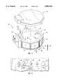
- FIG. 1demonstrates a perspective view of a portable spa of the present invention.
- FIG. 2demonstrates a partially exploded view of the portable spa shown in FIG. 1. A portion of the spa bath is cut away.
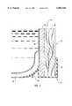
- FIG. 3demonstrates a partial cross-sectional view of the container shown in FIG. 2.
- FIG. 4demonstrates a perspective view of the portable spa pump assembly of the present invention.
- FIG. 5demonstrates a cutaway view of the electronics panel of the spa pump assembly shown in FIG. 4.
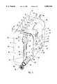
- FIG. 6demonstrates a side view of the assembly shown in FIG. 4 taken along lines 6--6 of FIG, 4.
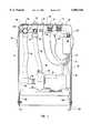
- FIG. 7demonstrates a view inside the rear shell of the assembly shown in FIG. 4 taken along lines 7--7 of FIG. 4.
- FIG. 8demonstrates a view inside the front shell of the assembly shown of FIG. 4 taken along lines 8--8 of FIG. 4.
- FIG. 9demonstrates a schematic view of the operation of the assembly shown in FIG. 4.
- FIG. 10demonstrates an alternate embodiment of a view inside the rear shell.
- Spa 10comprises a spa bath 12, a spa pump assembly 14 configured to be removably mounted to spa bath 12 and a lid 16 covering both spa bath 12 and assembly 14.
- FIG. 2demonstrates lid 16 exploded from spa bath 12 and assembly 14.
- assembly 14is removably coupled on opposing sides of a perimeter wall 34 of spa bath 12 atop rim 21 of wall 34.
- Assembly 14siphons water from within spa bath 12, filters the water, directs the water over wall 34 where the water is heated within assembly 14 and then directs the water back into spa bath 12.
- Assembly 14is an organized, portable self-contained unit which is readily transported and stored.
- spa bath 12is shown in FIG. 2 on a support surface.
- spa bath 12comprises (i) an outer container body 18; (ii) an inner liner 20 disposed against the inner surface of container body 18 and over the rim of container body 18; and (iii) eight foam clamps 24, 26 having an outer bulbous shape and an inner U-shape disposed over the interface between rim 22 of liner 20 and the rim of container body 18 to removably affix rim 22 of liner to body 18 and provide a cushioned rim 21 of wall 34.
- Clamp 26 below container 14is slightly smaller than the other seven clamps 24 to allow assembly 14 to be conveniently placed on spa bath 12 while providing large cushioned clamps 24.
- container body 18may be comprised of a variety of different elements.
- container body 18comprises eight different sections. Each section is comprised of a wooden panel 28, a corresponding foam panel 30 and a floor bracket 32 coupling wood and foam panels 28, 30 together.
- each wood panel 28includes on opposing sides thereof side brackets 36, each of which have a lip which receives an end of a respective connecting bracket 38.
- an angled plate 43is coupled to adjacent panels 28 and is disposed between panels 28 and floor brackets 32. Screws are disposed through floor brackets 32 and through opposing sides of plate 43 into T-nuts coupled to panels 28.
- spa bath 12may comprise a variety of different containers.
- Containers employed in the present inventionmay include a liner or may be operated without the use of a liner.
- Examples of containers which serve as examples of spa bath 12include a container made of acrylic, metal, steel, plywood, porcelain, fiberglass or an inflatable container having a band or girdle wrapped thereabout for supporting the inflatable container, and a variety of other containers presently known within the art.
- the liquid within spa bath 12comprises water which has been properly chemically treated before use and is tested and treated on an ongoing basis. Movable seats or sectional pieces may be placed into spa bath 12.
- Assembly 14will now be described in additional detail with reference to FIG. 4.
- Assembly 14comprises a pump 44, inlet plumbing 45, and outlet plumbing 47.
- Pump 44 and plumbing 45, 47are depicted in a schematic view in FIG. 9, which will be discussed in additional detail below.
- the word “plumbing”refers to at least one conduit, such as a pipe or a series of connected pipes, connectors and fittings.
- assembly 14further comprises means for removably securing pump 44, inlet plumbing 45, and outlet plumbing 47 to wall 34 of spa bath 12 as a self-contained assembly.
- assembly 14comprises U-shaped cover 46 at least partially surrounding and coupled to pump 44, inlet plumbing 45, and outlet plumbing 47.
- the phrase “self-contained assembly” or a substantially similar phraserefers to an assembly such as assembly 14 which is built as a compact, organized, cohesive single unit having pump 44 and inlet and outlet plumbing 45, 47 at least partially surrounded by cover 46.
- the phrase "self-contained assembly” or a substantially similar phraseincludes an assembly such as assembly 14 which has ports for plumbing 45, 47 extending through cover 46, control knobs on cover 46, and/or an electrical cord which extends through cover 46 to an electrical outlet.
- the phrase “self-contained assembly” or a substantially similar phraserefers to an assembly such as assembly 14 in which approximately half or more of the surface area of pump 44 and inlet and outlet plumbing 45, 47 are surrounded by cover 46. In another preferred embodiment, the phrase “self-contained assembly” or a substantially similar phrase refers to an assembly such as assembly 14 in which approximately three fourths or more of the surface area of pump 44 and inlet and outlet plumbing 45, 47 are surrounded by cover 46.
- the phrase "self-contained assembly” or a substantially similar phraserefers to an assembly such as assembly 14 wherein, upon placing the assembly 14 onto wall 34 of spa bath 12, pump 44, outlet plumbing 45, and inlet plumbing 47 are substantially surrounded by the opposing sides of wall 34 of spa bath 12 and cover 46.
- cover 46comprises (i) a first cover portion such as shell 48; and (ii) means attached to the first cover portion 48 for removably securing pump 44 and first cover portion 48 to wall 34 of spa bath 12.
- the means for removably securing pump 44 and first cover portion 48 to wall 34comprises (i) a second cover portion, such as shell 50, coupled to pump 44, and (ii) means for coupling first shell 48 to second shell 50.
- each shell 48, 50is comprised of a plastic material which is lightweight, and flexible enough to allow assembly 14 to be placed on wall 34, yet sturdy enough to substantially house and protect the internal components of assembly 14.
- Shells 48, 50each have a concave configuration.
- Shell 48has a face 81 and two side members 82, 83 extending from face 81.
- Shell 50includes a face 84, side members 87, 89 extending from opposing sides of face 84, and a resting bracket 104, preferably metal, coupled to face 84 and member 87, 89.
- the concave configurations of shells 48, 50combine to house and maintain the internal components of assembly 14 such that assembly 14 is conveniently portable.
- first shell 48which is disposed within the liquid within spa bath 12 is an example of a wet leg 49 of cover 46 and a lower portion of shell 50 is an example of a dry leg 51 of cover 46.
- the coupled upper portions of first and second shells 48, 50are collectively an example of an intermediate portion 52 of the cover 46 coupling wet leg 49 to dry leg 51.
- intermediate portion 52is a single integral piece.
- a mounting groove 61A of cover 46is formed between wet leg 49 and dry leg 51.
- groove 61Ahas an upper bulbous portion 73 and a lower, rectangular portion 75. It will be appreciated, however, that groove 61A may have a rectangular cross section throughout or a variety of other configurations which allow groove 61A to mate with the wall of a spa.
- Wet leg 49is configured to be disposed within liquid within spa bath 12 while dry leg 51 is configured to be disposed outside of spa bath 12.
- Wet leg 49includes a plurality of inlet and outlet ports which extend therethrough. Port fittings of the respective inlet and outlet plumbing 45, 47 couple to cover 46 within these ports of wet leg 49.
- wet leg 49 of cover 46includes an inlet port through which a port fitting 59 of inlet plumbing system 45 is disposed, port fitting 59 defining a port 63 for liquid to flow into inlet plumbing 45.
- Filter housing 54 of inlet plumbing 45couples to port fitting 59. Fluid flows from spa bath 12 through port fitting 59 and filter housing 54 into pump 44.
- Perforated cover 58is disposed on filter housing 54 to prevent large objects from entering inlet plumbing 45.
- wet leg 49On the corner of wet leg 49 between face 81 and side member 82, wet leg 49 includes an outlet port which receives a corner outlet port fitting 60 of outlet plumbing 47. Fitting 60 defines a port 65 for enabling fluid from pump 44 to flow into spa bath 12. Corner outlet port fitting 60 is positioned so as to cause liquid to flow in a circular, whirlpool motion about spa bath 12.
- Front outlet port fittings 61, 62 of outlet plumbing 47 disposed in outlet ports in face 81 of wet leg 49are also designed to allow liquid from pump 44 to flow into spa bath 12.
- Port fittings 61, 62are positioned so as to focus water massaging action on the neck and 1 back of the user rather than creating a whirlpool action as performed by port 65 defined by corner outlet port fitting 60.
- outlet ports 65, 67, 69 defined by respective port fittings 60, 61, 62can be used to create a bubbling, whirlpooling action which massages the user while the user enjoys basking in the warm circulating liquid within spa bath 12.
- Assembly 14thus provides for a plurality of outlet ports having a variety of different functions and orientations to massage different parts of the body of the user.
- Cushion 64is disposed on intermediate portion 52 of cover 46 to provide for the user a convenient place to rest the user's neck and shoulders while enjoying the massaging and whirlpooling action from assembly 14. A user is thus able to rest a portion of the user's body on the cushion while placing another portion of the user's body adjacent one or more outlet ports 67, 69 located substantially below cushion 64 on cover 46.
- a decal 66may be placed on intermediate portion 52 of assembly 14 thereby allowing a manufacturer to advertise and provide warnings and other information relating to the manufacturer's product and also permitting the placement of indicia 68 such as words and markings adjacent controls 70 to thereby instruct the user on the use of controls 70.
- FIG. 5demonstrates certain control knobs 70 associated with assembly 14. As shown, control knobs 70 located on intermediate portion 52 of assembly 14 allow for a variety of different options and activities. Control knobs 70 are strategically positioned in this location in order to avoid being immersed in the liquid within container while still permitting the convenient control of assembly 14 by the user while the user is enjoying system 10.
- Primer cap 80is removably coupled to intermediate portion 52 of assembly 14 and permits convenient access into inlet plumbing 45, thereby allowing the user to prime pump 44 before using pump 44.
- Assembly 14further includes means for selectively directing the flow of liquid in a desired direction, such as a diverter having a control knob 78 located on intermediate portion 52 of cover 46. Diverter knob 78 allows the user to selectively divert liquid to corner port 65, front ports 67, 69, or both corner port 65 and front ports 67, 69. In another embodiment, assembly 14 is manufactured without a diverter, allowing liquid to flow constantly to front ports 67, 69 and corner port 65 while assembly 14 is in use.
- a diverterhaving a control knob 78 located on intermediate portion 52 of cover 46. Diverter knob 78 allows the user to selectively divert liquid to corner port 65, front ports 67, 69, or both corner port 65 and front ports 67, 69.
- assembly 14is manufactured without a diverter, allowing liquid to flow constantly to front ports 67, 69 and corner port 65 while assembly 14 is in use.
- Assembly 14further comprises means for selectively enabling air to enter spa bath 12 along with the liquid discharged through outlet plumbing 47.
- air control knob 72allows the user to control the amount of the air desired to flow through ports 65, 67, 69.
- An on/off button 74allows the user to selectively turn assembly 14 on and off.
- FIG. 6is a view of assembly 14 taken at 6-6.
- Groove 61Ais disposed on wall 34.
- clamp 26is disposed on opposing sides of rim 22 of elastomeric liner 20 thereby retaining liner 20 on opposing sides of container body 18.
- Intermediate portion 52 of cover 46is configured to be disposed on rim 21 of spa bath 12 between wet leg 49 and dry leg 51.
- an example of means for coupling first shell 48 to second shell 50comprises coupling plate 85.
- Shells 48, 50are coupled to plate 85 through the use of screws, or bolts for example.
- decal 66is also coupled to the upper portions of shells 49, 51 with the same screws or bolts used to couple shells 49, 51 to plate 85.
- shells 48, 50flex outwardly when the user disposes assembly 46 on wall 34, then grip wall 34 without forming a liquid tight seal between wet leg 49 and wall 34.
- wet leg 49is not designed to seal against wall 34, one or more spaces exist between wet leg 49 and wall 34 to allow liquid to flow between wet leg 49 and wall.
- wet leg 49is sealed against the entry of water therein, such as by having a rear face coupled to side members 82, 83 which prevents water from leaking into wet leg 49, or by being configured to be sealed against wall 34, for example.
- Cover 46is removably coupled to spa bath 12 by being configured to have groove 61 of cover 46 having upper bulbous portion 73 disposed about the bulbous shaped outer portion of clamp 26 of wall 34 and a rectangular portion 75 disposed against the remainder of wall 34.
- the configuration of cover 46protects pump 44 and plumbing 45, 47 from damage and makes pump 44 and plumbing 45, 47 conveniently transportable. It will be appreciated however that although cover 46 has been described in detail, cover 46 may be configured in a variety of different manners. For example, it will be appreciated that cover 46 and a rim of a spa bath may have a variety of different configurations which will allow device 14 to be removably coupled to a spa bath, such as through the use of gravity alone.
- Pump 44is coupled to mounting bracket 104 of shell 50 through the use of bolts 106. Bracket 104 is coupled through the use of bolts 108 to side cover plate 110 of shell 50 which is coupled to shell member 89 of shell 50. Because of the configuration of pump 44 and inlet and outlet plumbing 45, 47, pump 44 provides liquid to a variety of different ports at different locations.
- assembly 14comprises means for heating liquid within spa bath 12.
- the means for heating the liquidcomprises a heat recovery system.
- heatis transferred from pump 44 to liquid flowing through pump 44.
- pump 44while pumping liquid through the over-the-rim inlet and outlet plumbing 45, 47, friction heats the liquid.
- Heat provided by the heat recovery systemis thus a combination of frictionally generated heat and heat transferred from pump 44.
- Pump 44thus serves as a source of fluid flow and also as an example of means for heating liquid.
- a heating elementalso heats the liquid within spa bath 12.
- Assembly 14further comprises means electrically coupled to the means for heating liquid within the spa bath for sensing the temperature of the liquid within spa bath 12 and for activating the means for heating the liquid when the temperature of the liquid drops below a desired, selected temperature.
- the means electrically coupled to the means for heating liquid for sensing the temperature of the liquid and for activating the means for heating liquid when the temperature of the liquid drops below a desired, selected temperaturecomprises (i) a temperature sensor 121; (ii) a thermostat electrically coupled to sensor 121 and to pump 44; and (iii) a thermostat control knob 76.
- the thermostat and related circuitryare disposed in an electronics console 122 mounted to side housing plate 1 10 of second shell 50 of cover 49.
- Thermostat control knob 76is electrically coupled to the thermostat within electronics console 122 and allows a user to select a desired temperature for the liquid within the spa. In another embodiment, as discussed below, the thermostat is electrically coupled to sensor 121, knob 76 and a heating element.
- Pump 44includes means for providing electrical power to pump 44, including an electrical cord electrically coupled to an electrical outlet, a battery, or a generator, or console 122, as shown. Pump 44 also includes a drain plug for draining pump 44 in the event of prolonged storage or exposure to freezing temperatures.
- pump 44 employed in the present inventioncomprises an Ultra-Jet pump manufactured by VICO Products Manufacturing Company, Incorporated, So. El Monte, Calif. 91733, swimming pool or spa pump, model no. PUULS10138GR, one horsepower, Ultima SD/CS 115V, 9.9A, 60 cy., 1-spd.
- cover 46since cover 46 is readily opened, a variety of different pumps may be employed, such as AC pumps, DC pumps, single, double, or variable speed pumps.
- Inlet plumbing 45comprises a first inlet conduit 86 having (i) a pump end 88 coupled to the inlet end of pump 44, (ii) an inlet end 92 disposed within the liquid in spa bath 12, the inlet end including port fitting 59 and (iii) an intermediate portion 94 coupling inlet end 92 to pump end 88 of conduit 86.
- Conduit 86includes filter housing 54 which houses a filter 56 removably coupled within filter housing 54. Filter 56 is thus removably coupled to first inlet conduit 86.
- Outlet plumbing 47comprises a first outlet conduit 96 having (i) a pump end 98 coupled to the outlet end 135 of pump 44, (ii) a outlet end 100 including outlet port fitting 60, and (iii) an intermediate portion 102 coupling pump end 98 to outlet end 100. A cutaway portion of intermediate portion 102 is shown in FIG. 6.
- Outlet plumbing 47further comprises a second outlet conduit 116.
- Second conduit 116extends from first conduit 96 and terminates in and includes at least one port fitting 61.
- the diverter mechanism coupled to diverter knob 78is disposed within the joint 112 coupling first conduit 96 to second conduit 116.
- the diverterselectively directs liquid flowing from pump 44 between (i) a downstream portion 114 of first conduit 96 and/or (ii) second conduit 116.
- a third outlet conduit 118extends from second outlet conduit 116 and terminates in and includes at least one port fitting 62. The diverter allows liquid to flow through port 65, and/or ports 67, 69.
- wet leg 49does not seal in a water tight fashion against spa bath 12, but instead allows water to flow between wet leg 49 and spa bath 12.
- Wet leg 49 and wall 34thus define an internal cove in which sensor 121 is maintained immersed in liquid.
- Wet leg 49thus allows water to flow into the cavity while nevertheless protecting sensor 121 from the activities occurring within spa bath 12.
- Electronics console 122has a power cord 128 for coupling to a power source such as a wall mounted outlet and to power cord 132 extending to pump 44.
- a power sourcesuch as a wall mounted outlet
- power cord 132extending to pump 44.
- electronics console 122is the mini-pack 1-120, option RD1, Gecko Electronic Incorporated, Made in Canada, 120 VAC, 12A to pump, input 120 VAC, 50/60 Hz, 15A, Ozone 120 VAC 3A.
- console 122When the temperature of the liquid in spa bath 12 drops below the desired temperature as sensed by temperature sensor 121, electronics console 122 causes pump 44 to pump water, thereby heating the water to the desired temperature.
- console 122features an automatic filter cycle and freeze protection setting. At one setting if pump 44 has not been operated for three hours, pump 44 will begin circulating liquid for 20 minutes to filter any impurities. Also, if the water temperature falls below 40° F., pump 44 will begin circulating and heating the liquid to prevent the liquid from freezing.
- assembly 14comprises means for selectively enabling air to enter spa bath 12 along with the liquid discharged through outlet plumbing 47.
- the means for selectively enabling air to entercomprises an air inlet system and an air outlet system.
- the air outlet systemcomprises a first air outlet conduit 124 which terminates in corner port fitting 60 and second and third air outlet conduits 126, 127 which terminate in respective front port fittings 61, 62. Venturi valves in fittings 60, 61, 62 draw air through the air outlet conduits.
- cushion 64is disposed within a recess formed in shell 48 and abuts a lip 132 of upper housing plate 85. It will be appreciated, however, that cushion 64 may be configured in a variety of different configurations such as by having cushion 64 be disposed against a front shell having no such recess formed therein. In one embodiment, for example, plate 85 does not contain lip 132 because no recess is formed in shell 48.
- First inlet conduit 86has an opening at an upper portion thereof covered by primer cap 80 which the user removes to pour liquid such as water into conduit 86 to prime pump 44 before use.
- Outlet system 47includes a junction 112 at which second conduit 116 begins.
- Junction 112includes the diverter mechanism coupled to diverter knob 78 for selectively directing liquid flowing from pump 44 between a downstream portion 114 of first conduit 96 and/or second conduit 116.
- Air inlet control knob 72opens air inlet conduit 136 which couples to first air outlet conduit 124 terminating in port fitting 60 and second air outlet conduit 126 terminating in port fittings 61.
- Third air outlet conduit 127extends from conduit 126. Air is sucked into air inlet conduit 136 and through air outlet conduits 124, 126, 127 and through respective port fittings 60, 61, 62.
- a second side cover plate 138 of shell 50is also shown in FIG. 7.
- FIG. 8demonstrates the junctions 140, 141 between respective front port fittings 61, 62 coupled to cover 46 and outlet conduits 116, 118.
- Filter housing 54 at inlet end 92 of first inlet conduit 86is coupled to fitting 59 of first inlet conduit 86.
- Filter 56is removably coupled to filter housing 54. Filter 56 can be removed for cleaning and replacement.
- a second inlet conduit 142is coupled to first inlet conduit 86 and to cover 46 by being disposed through an inlet port in cover 46. Conduit 142 allows non-filtered liquid to enter pump 44.
- third air outlet conduit 127is shown extending from second air outlet conduit 126 and terminating in port fittings 62.
- pump 44Before operating pump 44, pump 44 should be primed by opening primer cap 80 and pouring water into inlet conduit 86. Pump 44 draws liquid from spa bath 12 through conduit filter 56 and through non-filtered second inlet conduit 142. Pump 44 then discharges water through first outlet conduit 96 which branches into second outlet conduit 116 and a downstream portion 114 of first conduit 96. Diverter control knob 78 controls the diverter mechanism 134 which allows liquid to flow into corner port 65 and/or front ports 67, 69.
- Air control knob 72selectively allows air to flow into air inlet conduit 136 which branches into air outlet conduits 124 and 126 which allow air to flow into corner port 65 and front ports 67, 69.
- Temperature sensor 121senses the temperature of the liquid within spa bath 12 and communicates the measurement of the temperature to electronics console 122 which also receives the desired temperature measurement from temperature control knob 76. Upon the temperature dropping below the temperature set by temperature control knob 76, the thermostat in electronics console 122 causes pump 44 to run, thereby warming the liquid.
- FIG. 10is an alternative view inside rear shell 50 from the view shown in FIG. 7.
- the means for heating liquid within the spacomprises pump 44 and a heating element.
- the heating elementis disposed within a portion of conduit 96 located between outlet end 135 of pump and junction 112.
- the portion of conduit 96 in which the heating element is disposedcomprises a stainless steel tube 154.
- the heating elementcomprises first and second terminals 150, 152 extending from a U-shaped body (not shown) which is disposed within tube 154. Terminals 150 and 152 are welded to tube 154 and extend through apertures in tube 154. Posts 160, 162 are coupled to tube 154 to receive a cover (now shown) which covers terminals 150, 152.
- the heating elementis electrically coupled to sensor 121 by being electrically coupled by electrical cord 156 to pump 44. In one embodiment, when a low speed of pump 44 is activated, the heating element is also activated, heating the liquid within tube 154.
- Electrical cord 156is also coupled to means for preventing overheating of assembly 14.
- the means for preventing overheating of assembly 14comprises a microswitch 158 mounted on tube 154 which is coupled to a pressure sensor (not shown) disposed within tube 154.
- microswitch 158is screwed through an aperture in tube 154 into the pressure sensor and comprises a 120 volt microswitch.
- Microswitch 158terminates electrical power to the heating element when there is insufficient water pressure within tube 154 and therefore insufficient water pressure within assembly 14.
- assembly 14further comprises a high limit temperature probe disposed within conduit 96 downstream from the heating element. Electrical cord 164 electrically couples the high limit temperature probe to console 122.
- the high limit temperature probemay be located within conduit 96 adjacent location 166, for example. The high limit temperature probe senses liquid at 122° or hotter and deactivates assembly 14 if the liquid is at the temperature of 122° or more. This prevents pump 44 and the heating element from being activated.
- pump 44 of FIG. 10comprises an Ultra-Jet pump manufactured by VICO Products Manufacturing Company, Incorporated, So. El Monte, Calif. 91733, Model No. PUULS215138GRH, 1.5 horsepower, true rate, 60 cy., 2-spd, Ultima, SD-CS, 115V, 11.9A/3.3A.
- This pumphas a low speed and a high speed.
- the console 122 shown in FIG. 10is manufactured by Chang Chen Instruments, Taipei, Taiwan, Model No. EJ-06.
- the low speed side of pump 44, pressure switch 158 and the heating elementare all wired in a series loop.
- Console 122may be programmed such that as temperature sensor 121 within wet leg 48 senses a temperature of liquid lower than the desired temperature selected by the user with temperature control knob 76, control console 122 activates pump 44 to the low speed, thereby activating the heating element and heating the liquid to the desired temperature.
- the heating elementis electrically coupled to the high speed portion of pump 44 and activated during high speed operation. Microswitch 158 prevents activation of the heating element if water pressure in tube 154 is too low.
- assembly 14can be programmed such that upon pressing on/off button 74 one or more times pump 44 changes speeds or is deactivated. In one embodiment, if the user presses on/off button 74 during operation of pump 44, pump 44 is deactivated unless the temperature is below the desired temperature, in which case the low speed is activated in order to heat the liquid until reaching the desired temperature.
- the heating elementis directly electrically coupled to console 122, rather than being electrically coupled to console 122 through pump 44. While a variety of different examples of means for heating liquid have been disclosed, it will be appreciated that these are only examples and a variety of different heating means and electrical couplings therefor may be employed consistent with the objects of the present invention.
Landscapes
- Health & Medical Sciences (AREA)
- Public Health (AREA)
- Epidemiology (AREA)
- Pain & Pain Management (AREA)
- Physical Education & Sports Medicine (AREA)
- Rehabilitation Therapy (AREA)
- Life Sciences & Earth Sciences (AREA)
- Animal Behavior & Ethology (AREA)
- General Health & Medical Sciences (AREA)
- Veterinary Medicine (AREA)
- Devices For Medical Bathing And Washing (AREA)
Abstract
Description
Claims (36)
Priority Applications (1)
| Application Number | Priority Date | Filing Date | Title |
|---|---|---|---|
| US08/996,616US6003166A (en) | 1997-12-23 | 1997-12-23 | Portable spa |
Applications Claiming Priority (1)
| Application Number | Priority Date | Filing Date | Title |
|---|---|---|---|
| US08/996,616US6003166A (en) | 1997-12-23 | 1997-12-23 | Portable spa |
Publications (1)
| Publication Number | Publication Date |
|---|---|
| US6003166Atrue US6003166A (en) | 1999-12-21 |
Family
ID=25543111
Family Applications (1)
| Application Number | Title | Priority Date | Filing Date |
|---|---|---|---|
| US08/996,616Expired - Fee RelatedUS6003166A (en) | 1997-12-23 | 1997-12-23 | Portable spa |
Country Status (1)
| Country | Link |
|---|---|
| US (1) | US6003166A (en) |
Cited By (88)
| Publication number | Priority date | Publication date | Assignee | Title |
|---|---|---|---|---|
| US6227808B1 (en)* | 1999-07-15 | 2001-05-08 | Hydroair A Unit Of Itt Industries | Spa pressure sensing system capable of entrapment detection |
| US20030091440A1 (en)* | 2001-11-12 | 2003-05-15 | Patel Anil B. | Bilge pump |
| US6623245B2 (en) | 2001-11-26 | 2003-09-23 | Shurflo Pump Manufacturing Company, Inc. | Pump and pump control circuit apparatus and method |
| EP1219280A3 (en)* | 2000-11-01 | 2003-12-10 | Pleasure Time Products (Hong Kong) Limited | Portable spa |
| US20040117905A1 (en)* | 2002-12-23 | 2004-06-24 | Gruenwald David J. | Spa apparatus |
| US20040177438A1 (en)* | 2002-12-23 | 2004-09-16 | European Touch Holdings, Inc. | Spa apparatus |
| US6857967B2 (en)* | 2002-09-16 | 2005-02-22 | California Acrylic Industries | Water recreational apparatus with remote controllable valves |
| US6859953B1 (en) | 2002-09-13 | 2005-03-01 | Steven E. Christensen | Jet propulsion system for spa or jetted bath using control of air draw to Venturi jets with a three-way air control valve |
| US20050150635A1 (en)* | 2004-01-14 | 2005-07-14 | Luebke Paul W. | Modular cooling loop system |
| US20050183197A1 (en)* | 2002-12-23 | 2005-08-25 | Gruenwald David J. | Spa with plastic foot plate and seal therefore |
| US20050235406A1 (en)* | 2004-04-21 | 2005-10-27 | August Stephen D | Convection loop hot tub system |
| US20060072123A1 (en)* | 2003-01-25 | 2006-04-06 | Wilson John E | Methods and apparatus for making images including depth information |
| US7083392B2 (en) | 2001-11-26 | 2006-08-01 | Shurflo Pump Manufacturing Company, Inc. | Pump and pump control circuit apparatus and method |
| US20060289347A1 (en)* | 2005-06-27 | 2006-12-28 | Chekesha Anasa Haley | Dirt out |
| USD541060S1 (en) | 2006-04-03 | 2007-04-24 | European Touch Holdings, Inc. | Spa |
| US20070095301A1 (en)* | 2005-10-28 | 2007-05-03 | Boylan Carroll J | Pet washing station |
| US7252431B1 (en)* | 2003-10-28 | 2007-08-07 | Caramanna A Gregory | Water temperature monitoring apparatus |
| USD549999S1 (en) | 2006-04-03 | 2007-09-04 | European Touch Holdings, Inc. | Enclosure for a spa |
| US20070226897A1 (en)* | 2006-03-31 | 2007-10-04 | European Touch Holdings, Inc. | Seat for spa |
| US20070228785A1 (en)* | 2006-04-03 | 2007-10-04 | European Touch Holdings, Inc. | Arm rest for spa |
| US20080066224A1 (en)* | 2006-09-15 | 2008-03-20 | Russ Wooten | Push button incremental air control valve |
| US20080168599A1 (en)* | 2007-01-12 | 2008-07-17 | Caudill Dirk A | Spa system with flow control feature |
| US20080184481A1 (en)* | 2006-07-14 | 2008-08-07 | European Touch Holdings, Inc. | Contour spa basin with impeller enclosure |
| US20090064404A1 (en)* | 2007-09-07 | 2009-03-12 | Hans Frei | Modular swimming pool |
| US20090172873A1 (en)* | 2007-11-07 | 2009-07-09 | Ludlow David J | Spa construction and installation system |
| US20090241252A1 (en)* | 2008-03-26 | 2009-10-01 | Shanghai Qing Xu Plastic Products Co., Ltd | Mobile inflatable bubble massage bathtub |
| US20090312680A1 (en)* | 2008-06-11 | 2009-12-17 | Jtl Enterprises Inc. (A Delaware Corporation) | Apparatus for dry hydro-therapy body massage with fluid spray control device |
| US20100223721A1 (en)* | 2009-03-05 | 2010-09-09 | May Manufacturing, LLC | Combination bathtub and spa |
| WO2010101545A1 (en) | 2009-03-05 | 2010-09-10 | May Manufacturing, LLC | Combination bathtub and spa |
| US20110004993A1 (en)* | 2007-09-07 | 2011-01-13 | Thomas J. Germinario | Swimming pool with eductor jets |
| US20110023225A1 (en)* | 2007-11-27 | 2011-02-03 | Victor Kaykov | Portable spa with variable speed throttling water massage system |
| US20110056486A1 (en)* | 2008-05-12 | 2011-03-10 | North Richard F | Cover for Solar Panel |
| US7937783B2 (en) | 2006-06-13 | 2011-05-10 | European Touch Holdings, Inc. | Impeller enclosure |
| US20150020306A1 (en)* | 2013-07-18 | 2015-01-22 | Intex Recreation Corp. | Inflatable spa |
| USD772420S1 (en)* | 2014-10-27 | 2016-11-22 | Sundance Spas, Inc. | Spa |
| USD774656S1 (en)* | 2015-12-21 | 2016-12-20 | Walkins Manufacutring Corporation | Impeller shroud |
| US9528524B2 (en) | 2011-10-31 | 2016-12-27 | Regal Beloit America, Inc. | Pump freeze protection |
| US9573038B1 (en)* | 2015-10-08 | 2017-02-21 | Waterway Plastics | Variable speed swim spa system |
| US9855479B2 (en) | 2016-01-29 | 2018-01-02 | Watkins Manufacturing Corporation | Swimming system current generator |
| US10076874B2 (en) | 2013-11-25 | 2018-09-18 | Intex Marketing Ltd. | Welding process and product for inflatable product |
| US10213362B2 (en) | 2012-02-24 | 2019-02-26 | Hobson A. Howell | Portable hydro-thermal therapy system for use with a vessel for containing water and method for use of same |
| US10388183B2 (en) | 2015-02-27 | 2019-08-20 | Icon Health & Fitness, Inc. | Encouraging achievement of health goals |
| US20200214507A1 (en)* | 2019-01-08 | 2020-07-09 | Ray Augustus, SR. | Bathtub Installation Aide |
| US10709925B2 (en) | 2013-03-14 | 2020-07-14 | Icon Health & Fitness, Inc. | Strength training apparatus |
| US10758767B2 (en) | 2013-12-26 | 2020-09-01 | Icon Health & Fitness, Inc. | Resistance mechanism in a cable exercise machine |
| US10786706B2 (en) | 2018-07-13 | 2020-09-29 | Icon Health & Fitness, Inc. | Cycling shoe power sensors |
| US10918905B2 (en) | 2016-10-12 | 2021-02-16 | Icon Health & Fitness, Inc. | Systems and methods for reducing runaway resistance on an exercise device |
| US10940360B2 (en) | 2015-08-26 | 2021-03-09 | Icon Health & Fitness, Inc. | Strength exercise mechanisms |
| US10994173B2 (en) | 2016-05-13 | 2021-05-04 | Icon Health & Fitness, Inc. | Weight platform treadmill |
| US11000730B2 (en) | 2018-03-16 | 2021-05-11 | Icon Health & Fitness, Inc. | Elliptical exercise machine |
| US11013960B2 (en) | 2016-03-18 | 2021-05-25 | Icon Health & Fitness, Inc. | Exercise system including a stationary bicycle and a free weight cradle |
| US11033777B1 (en) | 2019-02-12 | 2021-06-15 | Icon Health & Fitness, Inc. | Stationary exercise machine |
| US11058914B2 (en) | 2016-07-01 | 2021-07-13 | Icon Health & Fitness, Inc. | Cooling methods for exercise equipment |
| US11058913B2 (en) | 2017-12-22 | 2021-07-13 | Icon Health & Fitness, Inc. | Inclinable exercise machine |
| US11187285B2 (en) | 2017-12-09 | 2021-11-30 | Icon Health & Fitness, Inc. | Systems and methods for selectively rotationally fixing a pedaled drivetrain |
| US11244751B2 (en) | 2012-10-19 | 2022-02-08 | Finish Time Holdings, Llc | Method and device for providing a person with training data of an athlete as the athlete is performing a swimming workout |
| US11298577B2 (en) | 2019-02-11 | 2022-04-12 | Ifit Inc. | Cable and power rack exercise machine |
| US11326673B2 (en) | 2018-06-11 | 2022-05-10 | Ifit Inc. | Increased durability linear actuator |
| US11400478B2 (en)* | 2018-01-31 | 2022-08-02 | Bestway Inflatables & Material Corp. | Waterfall providing apparatus and system for pool or spa |
| US11451108B2 (en) | 2017-08-16 | 2022-09-20 | Ifit Inc. | Systems and methods for axial impact resistance in electric motors |
| US11534651B2 (en) | 2019-08-15 | 2022-12-27 | Ifit Inc. | Adjustable dumbbell system |
| US11534654B2 (en) | 2019-01-25 | 2022-12-27 | Ifit Inc. | Systems and methods for an interactive pedaled exercise device |
| US11554079B2 (en)* | 2019-07-15 | 2023-01-17 | Wexco Incorporated | Integrated manifold and valve assembly |
| WO2023286030A1 (en)* | 2021-07-15 | 2023-01-19 | Intex Industries Xiamen Co. Ltd. | An airway system of a massage pool, comprises an air pump and an airway unit |
| US11565148B2 (en) | 2016-03-18 | 2023-01-31 | Ifit Inc. | Treadmill with a scale mechanism in a motor cover |
| US11673036B2 (en) | 2019-11-12 | 2023-06-13 | Ifit Inc. | Exercise storage system |
| US11700905B2 (en) | 2014-03-10 | 2023-07-18 | Ifit Inc. | Pressure sensor to quantify work |
| US11794070B2 (en) | 2019-05-23 | 2023-10-24 | Ifit Inc. | Systems and methods for cooling an exercise device |
| US11850497B2 (en) | 2019-10-11 | 2023-12-26 | Ifit Inc. | Modular exercise device |
| US11878199B2 (en) | 2021-02-16 | 2024-01-23 | Ifit Inc. | Safety mechanism for an adjustable dumbbell |
| EP4325001A1 (en)* | 2022-08-16 | 2024-02-21 | Bestway Inflatables & Material Corp. | Non-inflatable above-ground pool |
| US11931621B2 (en) | 2020-03-18 | 2024-03-19 | Ifit Inc. | Systems and methods for treadmill drift avoidance |
| US11951377B2 (en) | 2020-03-24 | 2024-04-09 | Ifit Inc. | Leaderboard with irregularity flags in an exercise machine system |
| US12029961B2 (en) | 2020-03-24 | 2024-07-09 | Ifit Inc. | Flagging irregularities in user performance in an exercise machine system |
| US12029935B2 (en) | 2021-08-19 | 2024-07-09 | Ifit Inc. | Adjustment mechanism for an adjustable kettlebell |
| US12128001B2 (en) | 2021-07-15 | 2024-10-29 | Intex Marketing Ltd. | Airway structure of a massage pool with compensation function and massage pool |
| US12133829B2 (en) | 2021-07-15 | 2024-11-05 | Intex Marketing Ltd. | Airway structure of a massage pool with a control valve |
| US12150911B2 (en) | 2021-07-15 | 2024-11-26 | Intex Marketing Ltd. | Air connection piping device for a massage pool, a pool body of a massage pool and a massage pool |
| US12176009B2 (en) | 2021-12-30 | 2024-12-24 | Ifit Inc. | Systems and methods for synchronizing workout equipment with video files |
| US12219201B2 (en) | 2021-08-05 | 2025-02-04 | Ifit Inc. | Synchronizing video workout programs across multiple devices |
| US12263371B2 (en) | 2021-04-27 | 2025-04-01 | Ifit Inc. | Devices, systems, and methods for rotating a tread belt in two directions |
| US12280294B2 (en) | 2021-10-15 | 2025-04-22 | Ifit Inc. | Magnetic clutch for a pedaled drivetrain |
| US12350573B2 (en) | 2021-04-27 | 2025-07-08 | Ifit Inc. | Systems and methods for cross-training on exercise devices |
| US12350547B2 (en) | 2022-02-28 | 2025-07-08 | Ifit Inc. | Devices, systems, and methods for moving a movable step through a transition zone |
| EP4340687A4 (en)* | 2022-06-06 | 2025-07-30 | Belgravia Wood Ltd | SWIMMING POOL HUB DEVICE AND METHOD |
| US12409375B2 (en) | 2022-03-18 | 2025-09-09 | Ifit Inc. | Systems and methods for haptic simulation in incline exercise devices |
| US12433815B2 (en) | 2020-10-02 | 2025-10-07 | Ifit Inc. | Massage roller with pressure sensors |
| US12433822B2 (en)* | 2021-03-08 | 2025-10-07 | Bestway Inflatables & Material Corp. | Control box of massage pool and massage pool |
Citations (22)
| Publication number | Priority date | Publication date | Assignee | Title |
|---|---|---|---|---|
| US3273560A (en)* | 1963-08-05 | 1966-09-20 | Jacuzzi Bros Inc | Hydrotherapy unit |
| US3286712A (en)* | 1963-10-10 | 1966-11-22 | Roden Philip | Hydrotherapy apparatus |
| US3534730A (en)* | 1968-03-04 | 1970-10-20 | Jacuzzi Research Inc | Hydromassage apparatus |
| US3861384A (en)* | 1974-02-25 | 1975-01-21 | Samuel E Casternovia | Portable hydrotherapeutic device |
| US3911505A (en)* | 1968-04-08 | 1975-10-14 | Walter E Zaborowsky | Hydrotherapy apparatus |
| US3961382A (en)* | 1973-11-29 | 1976-06-08 | Associated Mills, Inc. | Hydrotherapy bath assembly |
| US4100917A (en)* | 1976-10-18 | 1978-07-18 | Dazey Products Co. | Hydrotherapy unit |
| US4127117A (en)* | 1977-07-14 | 1978-11-28 | Associated Mills, Inc. | Portable hydrotherapy bath assembly |
| US4225984A (en)* | 1979-04-05 | 1980-10-07 | Lindsey Donnie R | Portable therapeutic water massage mechanism |
| US4402094A (en)* | 1982-03-18 | 1983-09-06 | Sanders John T | Safety circulation system |
| US4630599A (en)* | 1986-01-31 | 1986-12-23 | Unidyne, Inc. | Hydromassage apparatus |
| US4665572A (en)* | 1985-11-01 | 1987-05-19 | Peter Davidson | Swimming pool therapy apparatus |
| US4774934A (en)* | 1986-04-02 | 1988-10-04 | Hara Health Industrial Co., Ltd. | Bubble bath assembly with nozzle outlet above water surface |
| US4942871A (en)* | 1987-09-29 | 1990-07-24 | Hara Health Industrial Co., Ltd. | Floatable bubble bath assembly |
| US4957101A (en)* | 1987-08-21 | 1990-09-18 | Hara Health Industrial Co., Ltd. | Portable bubble bath assembly |
| US5031255A (en)* | 1990-01-10 | 1991-07-16 | Associated Mills, Inc. | Whirlpool |
| US5283915A (en)* | 1992-08-10 | 1994-02-08 | Softub, Inc. | Power package for spa apparatus |
| US5335376A (en)* | 1989-03-09 | 1994-08-09 | Kaldewei Franz Dieter | Whirlpool bathtub |
| US5386598A (en)* | 1991-09-03 | 1995-02-07 | Franz Kaldewei Gmbh & Co. | Whirlpool bathtub with devices for generating jets of water and/or air |
| US5404598A (en)* | 1993-11-01 | 1995-04-11 | Hadsell; Richard Mcg. | Bathtub add on hydrotherapy apparatus |
| US5408707A (en)* | 1993-12-08 | 1995-04-25 | Wilson; Phillip M. | Portable spa apparatus |
| US5526538A (en)* | 1995-05-04 | 1996-06-18 | Hurrican Products Incorporated | Water circulation and heating system for spas |
- 1997
- 1997-12-23USUS08/996,616patent/US6003166A/ennot_activeExpired - Fee Related
Patent Citations (22)
| Publication number | Priority date | Publication date | Assignee | Title |
|---|---|---|---|---|
| US3273560A (en)* | 1963-08-05 | 1966-09-20 | Jacuzzi Bros Inc | Hydrotherapy unit |
| US3286712A (en)* | 1963-10-10 | 1966-11-22 | Roden Philip | Hydrotherapy apparatus |
| US3534730A (en)* | 1968-03-04 | 1970-10-20 | Jacuzzi Research Inc | Hydromassage apparatus |
| US3911505A (en)* | 1968-04-08 | 1975-10-14 | Walter E Zaborowsky | Hydrotherapy apparatus |
| US3961382A (en)* | 1973-11-29 | 1976-06-08 | Associated Mills, Inc. | Hydrotherapy bath assembly |
| US3861384A (en)* | 1974-02-25 | 1975-01-21 | Samuel E Casternovia | Portable hydrotherapeutic device |
| US4100917A (en)* | 1976-10-18 | 1978-07-18 | Dazey Products Co. | Hydrotherapy unit |
| US4127117A (en)* | 1977-07-14 | 1978-11-28 | Associated Mills, Inc. | Portable hydrotherapy bath assembly |
| US4225984A (en)* | 1979-04-05 | 1980-10-07 | Lindsey Donnie R | Portable therapeutic water massage mechanism |
| US4402094A (en)* | 1982-03-18 | 1983-09-06 | Sanders John T | Safety circulation system |
| US4665572A (en)* | 1985-11-01 | 1987-05-19 | Peter Davidson | Swimming pool therapy apparatus |
| US4630599A (en)* | 1986-01-31 | 1986-12-23 | Unidyne, Inc. | Hydromassage apparatus |
| US4774934A (en)* | 1986-04-02 | 1988-10-04 | Hara Health Industrial Co., Ltd. | Bubble bath assembly with nozzle outlet above water surface |
| US4957101A (en)* | 1987-08-21 | 1990-09-18 | Hara Health Industrial Co., Ltd. | Portable bubble bath assembly |
| US4942871A (en)* | 1987-09-29 | 1990-07-24 | Hara Health Industrial Co., Ltd. | Floatable bubble bath assembly |
| US5335376A (en)* | 1989-03-09 | 1994-08-09 | Kaldewei Franz Dieter | Whirlpool bathtub |
| US5031255A (en)* | 1990-01-10 | 1991-07-16 | Associated Mills, Inc. | Whirlpool |
| US5386598A (en)* | 1991-09-03 | 1995-02-07 | Franz Kaldewei Gmbh & Co. | Whirlpool bathtub with devices for generating jets of water and/or air |
| US5283915A (en)* | 1992-08-10 | 1994-02-08 | Softub, Inc. | Power package for spa apparatus |
| US5404598A (en)* | 1993-11-01 | 1995-04-11 | Hadsell; Richard Mcg. | Bathtub add on hydrotherapy apparatus |
| US5408707A (en)* | 1993-12-08 | 1995-04-25 | Wilson; Phillip M. | Portable spa apparatus |
| US5526538A (en)* | 1995-05-04 | 1996-06-18 | Hurrican Products Incorporated | Water circulation and heating system for spas |
Non-Patent Citations (1)
| Title |
|---|
| Spa to Go Installation (VHS Video Cassette Tape), Ohio Steel Industries. On information and belief, the Spa to Go Installation video was publicly available in Jul. 1996.* |
Cited By (145)
| Publication number | Priority date | Publication date | Assignee | Title |
|---|---|---|---|---|
| US6390781B1 (en) | 1999-07-15 | 2002-05-21 | Itt Manufacturing Enterprises, Inc. | Spa pressure sensing system capable of entrapment detection |
| US6227808B1 (en)* | 1999-07-15 | 2001-05-08 | Hydroair A Unit Of Itt Industries | Spa pressure sensing system capable of entrapment detection |
| EP1219280A3 (en)* | 2000-11-01 | 2003-12-10 | Pleasure Time Products (Hong Kong) Limited | Portable spa |
| US20030091440A1 (en)* | 2001-11-12 | 2003-05-15 | Patel Anil B. | Bilge pump |
| US6715994B2 (en) | 2001-11-12 | 2004-04-06 | Shurflo Pump Manufacturing Co., Inc. | Bilge pump |
| US7806664B2 (en) | 2001-11-12 | 2010-10-05 | Shurflo, Llc | Bilge pump |
| US7083392B2 (en) | 2001-11-26 | 2006-08-01 | Shurflo Pump Manufacturing Company, Inc. | Pump and pump control circuit apparatus and method |
| US6623245B2 (en) | 2001-11-26 | 2003-09-23 | Shurflo Pump Manufacturing Company, Inc. | Pump and pump control circuit apparatus and method |
| US6859953B1 (en) | 2002-09-13 | 2005-03-01 | Steven E. Christensen | Jet propulsion system for spa or jetted bath using control of air draw to Venturi jets with a three-way air control valve |
| US6968581B2 (en) | 2002-09-13 | 2005-11-29 | Christensen Steven E | Jet propulsion system for spa or jetted bath using control of air draw to venturi jets with a three-way air control valve |
| US20050097666A1 (en)* | 2002-09-13 | 2005-05-12 | Christensen Steven E. | Jet propulsion system for spa or jetted bath using control of air draw to venturi jets with a three-way air control valve |
| US6857967B2 (en)* | 2002-09-16 | 2005-02-22 | California Acrylic Industries | Water recreational apparatus with remote controllable valves |
| US20040177438A1 (en)* | 2002-12-23 | 2004-09-16 | European Touch Holdings, Inc. | Spa apparatus |
| US20040117905A1 (en)* | 2002-12-23 | 2004-06-24 | Gruenwald David J. | Spa apparatus |
| US7424753B2 (en) | 2002-12-23 | 2008-09-16 | European Touch Holdings, Inc. | SPA with plastic foot plate and seal therefor |
| US8028354B2 (en) | 2002-12-23 | 2011-10-04 | European Touch Holdings, Inc. | Spa apparatus |
| US20050183197A1 (en)* | 2002-12-23 | 2005-08-25 | Gruenwald David J. | Spa with plastic foot plate and seal therefore |
| US6880182B2 (en)* | 2002-12-23 | 2005-04-19 | European Touch Holdings, Inc. | Spa apparatus |
| US20100058533A1 (en)* | 2002-12-23 | 2010-03-11 | European Touch Holdings, Inc. | Spa apparatus |
| US7600273B2 (en) | 2002-12-23 | 2009-10-13 | European Touch Holdings, Inc. | Spa apparatus |
| US20060072123A1 (en)* | 2003-01-25 | 2006-04-06 | Wilson John E | Methods and apparatus for making images including depth information |
| US7252431B1 (en)* | 2003-10-28 | 2007-08-07 | Caramanna A Gregory | Water temperature monitoring apparatus |
| US20050150635A1 (en)* | 2004-01-14 | 2005-07-14 | Luebke Paul W. | Modular cooling loop system |
| US20050235406A1 (en)* | 2004-04-21 | 2005-10-27 | August Stephen D | Convection loop hot tub system |
| US20060289347A1 (en)* | 2005-06-27 | 2006-12-28 | Chekesha Anasa Haley | Dirt out |
| US20070095301A1 (en)* | 2005-10-28 | 2007-05-03 | Boylan Carroll J | Pet washing station |
| US7503284B2 (en)* | 2005-10-28 | 2009-03-17 | Boylan Carroll J | Pet washing station |
| US20070226897A1 (en)* | 2006-03-31 | 2007-10-04 | European Touch Holdings, Inc. | Seat for spa |
| US7490374B2 (en) | 2006-03-31 | 2009-02-17 | European Touch Holdings, Inc. | Spa apparatus |
| US20070226896A1 (en)* | 2006-03-31 | 2007-10-04 | European Touch Holdings, Inc. | Spa |
| US20070228785A1 (en)* | 2006-04-03 | 2007-10-04 | European Touch Holdings, Inc. | Arm rest for spa |
| USD549999S1 (en) | 2006-04-03 | 2007-09-04 | European Touch Holdings, Inc. | Enclosure for a spa |
| USD541060S1 (en) | 2006-04-03 | 2007-04-24 | European Touch Holdings, Inc. | Spa |
| US7937783B2 (en) | 2006-06-13 | 2011-05-10 | European Touch Holdings, Inc. | Impeller enclosure |
| US20080184481A1 (en)* | 2006-07-14 | 2008-08-07 | European Touch Holdings, Inc. | Contour spa basin with impeller enclosure |
| US20080066224A1 (en)* | 2006-09-15 | 2008-03-20 | Russ Wooten | Push button incremental air control valve |
| US20110035870A1 (en)* | 2007-01-12 | 2011-02-17 | Gecko Alliance Group Inc. | Spa system with flow control feature |
| US20080168599A1 (en)* | 2007-01-12 | 2008-07-17 | Caudill Dirk A | Spa system with flow control feature |
| US8104110B2 (en) | 2007-01-12 | 2012-01-31 | Gecko Alliance Group Inc. | Spa system with flow control feature |
| US20090064404A1 (en)* | 2007-09-07 | 2009-03-12 | Hans Frei | Modular swimming pool |
| US20110004993A1 (en)* | 2007-09-07 | 2011-01-13 | Thomas J. Germinario | Swimming pool with eductor jets |
| US20090172873A1 (en)* | 2007-11-07 | 2009-07-09 | Ludlow David J | Spa construction and installation system |
| US20110023225A1 (en)* | 2007-11-27 | 2011-02-03 | Victor Kaykov | Portable spa with variable speed throttling water massage system |
| US20090241252A1 (en)* | 2008-03-26 | 2009-10-01 | Shanghai Qing Xu Plastic Products Co., Ltd | Mobile inflatable bubble massage bathtub |
| US20110056486A1 (en)* | 2008-05-12 | 2011-03-10 | North Richard F | Cover for Solar Panel |
| US20090312680A1 (en)* | 2008-06-11 | 2009-12-17 | Jtl Enterprises Inc. (A Delaware Corporation) | Apparatus for dry hydro-therapy body massage with fluid spray control device |
| US8348872B2 (en) | 2008-06-11 | 2013-01-08 | Jtl Enterprises Inc. | Apparatus for dry hydro-therapy body massage with fluid spray control device |
| WO2010101545A1 (en) | 2009-03-05 | 2010-09-10 | May Manufacturing, LLC | Combination bathtub and spa |
| US20100223721A1 (en)* | 2009-03-05 | 2010-09-09 | May Manufacturing, LLC | Combination bathtub and spa |
| US8453275B2 (en)* | 2009-03-05 | 2013-06-04 | May Manufacturing LLC | Combination bathtub and spa |
| EP2403469A4 (en)* | 2009-03-05 | 2014-10-29 | May Mfg Llc | Combination bathtub and spa |
| US9528524B2 (en) | 2011-10-31 | 2016-12-27 | Regal Beloit America, Inc. | Pump freeze protection |
| US10213362B2 (en) | 2012-02-24 | 2019-02-26 | Hobson A. Howell | Portable hydro-thermal therapy system for use with a vessel for containing water and method for use of same |
| US11322240B2 (en) | 2012-10-19 | 2022-05-03 | Finish Time Holdings, Llc | Method and device for providing a person with training data of an athlete as the athlete is performing a running workout |
| US11810656B2 (en) | 2012-10-19 | 2023-11-07 | Finish Time Holdings, Llc | System for providing a coach with live training data of an athlete as the athlete is training |
| US11923066B2 (en) | 2012-10-19 | 2024-03-05 | Finish Time Holdings, Llc | System and method for providing a trainer with live training data of an individual as the individual is performing a training workout |
| US12340891B2 (en) | 2012-10-19 | 2025-06-24 | Finish Time Network LLC | System and method for providing a trainer with live training data of an individual as the individual is performing a training workout |
| US11244751B2 (en) | 2012-10-19 | 2022-02-08 | Finish Time Holdings, Llc | Method and device for providing a person with training data of an athlete as the athlete is performing a swimming workout |
| US11878206B2 (en) | 2013-03-14 | 2024-01-23 | Ifit Inc. | Strength training apparatus |
| US10953268B1 (en) | 2013-03-14 | 2021-03-23 | Icon Health & Fitness, Inc. | Strength training apparatus |
| US11338169B2 (en) | 2013-03-14 | 2022-05-24 | IFIT, Inc. | Strength training apparatus |
| US10709925B2 (en) | 2013-03-14 | 2020-07-14 | Icon Health & Fitness, Inc. | Strength training apparatus |
| US10815686B2 (en) | 2013-07-18 | 2020-10-27 | Intex Marketing Ltd. | Inflatable spa |
| US9254240B2 (en)* | 2013-07-18 | 2016-02-09 | Intex Recreation Corp. | Inflatable spa |
| US9468583B2 (en) | 2013-07-18 | 2016-10-18 | Intex Marketing Ltd. | Inflatable spa |
| US20150020306A1 (en)* | 2013-07-18 | 2015-01-22 | Intex Recreation Corp. | Inflatable spa |
| EP3021721A4 (en)* | 2013-07-18 | 2017-03-29 | Intex Marketing Ltd. | Inflatable spa |
| US11421434B2 (en)* | 2013-07-18 | 2022-08-23 | Intex Marketing Ltd. | Inflatable spa |
| US9468582B2 (en)* | 2013-07-18 | 2016-10-18 | Intex Marketing Ltd. | Inflatable spa |
| US9642771B2 (en) | 2013-07-18 | 2017-05-09 | Intex Marketing Ltd. | Inflatable spa |
| US10161148B2 (en) | 2013-07-18 | 2018-12-25 | Intex Marketing Ltd. | Inflatable spa |
| US11654638B2 (en) | 2013-11-25 | 2023-05-23 | Intex Marketing Ltd. | Welding process and product for inflatable product |
| US10076874B2 (en) | 2013-11-25 | 2018-09-18 | Intex Marketing Ltd. | Welding process and product for inflatable product |
| US11065823B2 (en) | 2013-11-25 | 2021-07-20 | Intex Marketing Ltd. | Welding process and product for inflatable product |
| US10967214B1 (en) | 2013-12-26 | 2021-04-06 | Icon Health & Fitness, Inc. | Cable exercise machine |
| US10758767B2 (en) | 2013-12-26 | 2020-09-01 | Icon Health & Fitness, Inc. | Resistance mechanism in a cable exercise machine |
| US11700905B2 (en) | 2014-03-10 | 2023-07-18 | Ifit Inc. | Pressure sensor to quantify work |
| USD772420S1 (en)* | 2014-10-27 | 2016-11-22 | Sundance Spas, Inc. | Spa |
| US10388183B2 (en) | 2015-02-27 | 2019-08-20 | Icon Health & Fitness, Inc. | Encouraging achievement of health goals |
| US10940360B2 (en) | 2015-08-26 | 2021-03-09 | Icon Health & Fitness, Inc. | Strength exercise mechanisms |
| US9573038B1 (en)* | 2015-10-08 | 2017-02-21 | Waterway Plastics | Variable speed swim spa system |
| USD774656S1 (en)* | 2015-12-21 | 2016-12-20 | Walkins Manufacutring Corporation | Impeller shroud |
| US9855479B2 (en) | 2016-01-29 | 2018-01-02 | Watkins Manufacturing Corporation | Swimming system current generator |
| US11794075B2 (en) | 2016-03-18 | 2023-10-24 | Ifit Inc. | Stationary exercise machine configured to execute a programmed workout with aerobic portions and lifting portions |
| US11013960B2 (en) | 2016-03-18 | 2021-05-25 | Icon Health & Fitness, Inc. | Exercise system including a stationary bicycle and a free weight cradle |
| US12023549B2 (en) | 2016-03-18 | 2024-07-02 | Ifit Inc. | Stationary exercise machine configured to execute a programmed workout with aerobic portions and lifting portions |
| US12029943B2 (en) | 2016-03-18 | 2024-07-09 | Ifit Inc. | Stationary exercise machine configured to execute a programmed workout with aerobic portions and lifting portions |
| US11565148B2 (en) | 2016-03-18 | 2023-01-31 | Ifit Inc. | Treadmill with a scale mechanism in a motor cover |
| US12029944B2 (en) | 2016-03-18 | 2024-07-09 | Ifit Inc. | Stationary exercise machine configured to execute a programmed workout with aerobic portions and lifting portions |
| US11779812B2 (en) | 2016-05-13 | 2023-10-10 | Ifit Inc. | Treadmill configured to automatically determine user exercise movement |
| US10994173B2 (en) | 2016-05-13 | 2021-05-04 | Icon Health & Fitness, Inc. | Weight platform treadmill |
| US11058914B2 (en) | 2016-07-01 | 2021-07-13 | Icon Health & Fitness, Inc. | Cooling methods for exercise equipment |
| US10918905B2 (en) | 2016-10-12 | 2021-02-16 | Icon Health & Fitness, Inc. | Systems and methods for reducing runaway resistance on an exercise device |
| US11451108B2 (en) | 2017-08-16 | 2022-09-20 | Ifit Inc. | Systems and methods for axial impact resistance in electric motors |
| US11708874B2 (en) | 2017-12-09 | 2023-07-25 | Ifit Inc. | Systems and methods for selectively rotationally fixing a pedaled drivetrain |
| US11680611B2 (en) | 2017-12-09 | 2023-06-20 | Ifit Inc. | Systems and methods for selectively rotationally fixing a pedaled drivetrain |
| US12270441B2 (en) | 2017-12-09 | 2025-04-08 | Ifit Inc. | Systems and methods for selectively rotationally fixing a pedaled drivetrain |
| US11187285B2 (en) | 2017-12-09 | 2021-11-30 | Icon Health & Fitness, Inc. | Systems and methods for selectively rotationally fixing a pedaled drivetrain |
| US11058913B2 (en) | 2017-12-22 | 2021-07-13 | Icon Health & Fitness, Inc. | Inclinable exercise machine |
| US11400478B2 (en)* | 2018-01-31 | 2022-08-02 | Bestway Inflatables & Material Corp. | Waterfall providing apparatus and system for pool or spa |
| US11000730B2 (en) | 2018-03-16 | 2021-05-11 | Icon Health & Fitness, Inc. | Elliptical exercise machine |
| US11596830B2 (en) | 2018-03-16 | 2023-03-07 | Ifit Inc. | Elliptical exercise machine |
| US11326673B2 (en) | 2018-06-11 | 2022-05-10 | Ifit Inc. | Increased durability linear actuator |
| US10786706B2 (en) | 2018-07-13 | 2020-09-29 | Icon Health & Fitness, Inc. | Cycling shoe power sensors |
| US12005315B2 (en) | 2018-07-13 | 2024-06-11 | Ifit Inc. | Cycling shoe power sensors |
| US20200214507A1 (en)* | 2019-01-08 | 2020-07-09 | Ray Augustus, SR. | Bathtub Installation Aide |
| US11389033B2 (en)* | 2019-01-08 | 2022-07-19 | Ray Augustus, SR. | Bathtub installation aide |
| US10905289B2 (en)* | 2019-01-08 | 2021-02-02 | Ray Augustus, SR. | Bathtub installation aide |
| US11534654B2 (en) | 2019-01-25 | 2022-12-27 | Ifit Inc. | Systems and methods for an interactive pedaled exercise device |
| US11642564B2 (en) | 2019-02-11 | 2023-05-09 | Ifit Inc. | Exercise machine |
| US11298577B2 (en) | 2019-02-11 | 2022-04-12 | Ifit Inc. | Cable and power rack exercise machine |
| US11452903B2 (en) | 2019-02-11 | 2022-09-27 | Ifit Inc. | Exercise machine |
| US11058918B1 (en) | 2019-02-12 | 2021-07-13 | Icon Health & Fitness, Inc. | Producing a workout video to control a stationary exercise machine |
| US11033777B1 (en) | 2019-02-12 | 2021-06-15 | Icon Health & Fitness, Inc. | Stationary exercise machine |
| US11426633B2 (en) | 2019-02-12 | 2022-08-30 | Ifit Inc. | Controlling an exercise machine using a video workout program |
| US11951358B2 (en) | 2019-02-12 | 2024-04-09 | Ifit Inc. | Encoding exercise machine control commands in subtitle streams |
| US11794070B2 (en) | 2019-05-23 | 2023-10-24 | Ifit Inc. | Systems and methods for cooling an exercise device |
| US11554079B2 (en)* | 2019-07-15 | 2023-01-17 | Wexco Incorporated | Integrated manifold and valve assembly |
| US11534651B2 (en) | 2019-08-15 | 2022-12-27 | Ifit Inc. | Adjustable dumbbell system |
| US12296247B2 (en) | 2019-10-11 | 2025-05-13 | Ifit Inc. | Modular exercise device |
| US11850497B2 (en) | 2019-10-11 | 2023-12-26 | Ifit Inc. | Modular exercise device |
| US11673036B2 (en) | 2019-11-12 | 2023-06-13 | Ifit Inc. | Exercise storage system |
| US11931621B2 (en) | 2020-03-18 | 2024-03-19 | Ifit Inc. | Systems and methods for treadmill drift avoidance |
| US12029961B2 (en) | 2020-03-24 | 2024-07-09 | Ifit Inc. | Flagging irregularities in user performance in an exercise machine system |
| US11951377B2 (en) | 2020-03-24 | 2024-04-09 | Ifit Inc. | Leaderboard with irregularity flags in an exercise machine system |
| US12433815B2 (en) | 2020-10-02 | 2025-10-07 | Ifit Inc. | Massage roller with pressure sensors |
| US12239872B2 (en) | 2021-02-16 | 2025-03-04 | Ifit Inc. | Safety mechanism for an adjustable dumbbell |
| US11878199B2 (en) | 2021-02-16 | 2024-01-23 | Ifit Inc. | Safety mechanism for an adjustable dumbbell |
| US12433822B2 (en)* | 2021-03-08 | 2025-10-07 | Bestway Inflatables & Material Corp. | Control box of massage pool and massage pool |
| US12350573B2 (en) | 2021-04-27 | 2025-07-08 | Ifit Inc. | Systems and methods for cross-training on exercise devices |
| US12263371B2 (en) | 2021-04-27 | 2025-04-01 | Ifit Inc. | Devices, systems, and methods for rotating a tread belt in two directions |
| US12133829B2 (en) | 2021-07-15 | 2024-11-05 | Intex Marketing Ltd. | Airway structure of a massage pool with a control valve |
| US12128000B2 (en) | 2021-07-15 | 2024-10-29 | Intex Marketing Ltd. | Airway system of a massage pool, comprises an air pump and an airway unit |
| WO2023286030A1 (en)* | 2021-07-15 | 2023-01-19 | Intex Industries Xiamen Co. Ltd. | An airway system of a massage pool, comprises an air pump and an airway unit |
| US12150911B2 (en) | 2021-07-15 | 2024-11-26 | Intex Marketing Ltd. | Air connection piping device for a massage pool, a pool body of a massage pool and a massage pool |
| US12128001B2 (en) | 2021-07-15 | 2024-10-29 | Intex Marketing Ltd. | Airway structure of a massage pool with compensation function and massage pool |
| US12219201B2 (en) | 2021-08-05 | 2025-02-04 | Ifit Inc. | Synchronizing video workout programs across multiple devices |
| US12029935B2 (en) | 2021-08-19 | 2024-07-09 | Ifit Inc. | Adjustment mechanism for an adjustable kettlebell |
| US12280294B2 (en) | 2021-10-15 | 2025-04-22 | Ifit Inc. | Magnetic clutch for a pedaled drivetrain |
| US12176009B2 (en) | 2021-12-30 | 2024-12-24 | Ifit Inc. | Systems and methods for synchronizing workout equipment with video files |
| US12350547B2 (en) | 2022-02-28 | 2025-07-08 | Ifit Inc. | Devices, systems, and methods for moving a movable step through a transition zone |
| US12409375B2 (en) | 2022-03-18 | 2025-09-09 | Ifit Inc. | Systems and methods for haptic simulation in incline exercise devices |
| EP4340687A4 (en)* | 2022-06-06 | 2025-07-30 | Belgravia Wood Ltd | SWIMMING POOL HUB DEVICE AND METHOD |
| US20240060321A1 (en)* | 2022-08-16 | 2024-02-22 | Bestway Inflatables & Material Corp. | Non-inflatable above-ground pool |
| EP4325001A1 (en)* | 2022-08-16 | 2024-02-21 | Bestway Inflatables & Material Corp. | Non-inflatable above-ground pool |
Similar Documents
| Publication | Publication Date | Title |
|---|---|---|
| US6003166A (en) | Portable spa | |
| EP1138307B1 (en) | Portable spa | |
| US5548852A (en) | Portable spa unit | |
| EP1913925B1 (en) | Portable spa | |
| AU2001242836B2 (en) | Foot massage apparatus | |
| US8296874B2 (en) | Basin for a foot spa | |
| US8453275B2 (en) | Combination bathtub and spa | |
| US20090089924A1 (en) | Spa tub apparatus | |
| US5807289A (en) | Water jet appliance | |
| JPH08215089A (en) | Portable bathtub device | |
| US5404598A (en) | Bathtub add on hydrotherapy apparatus | |
| EP2403469B1 (en) | Combination bathtub and spa | |
| US20240374416A1 (en) | Cold Tub with Warming Pockets | |
| CA2674331A1 (en) | Bypass system to control liquid volume | |
| US5095559A (en) | Heating apparatus | |
| US5815854A (en) | Sectional portable hot tub | |
| JPH01500489A (en) | Instant whole body hydromassage device | |
| US5031255A (en) | Whirlpool | |
| US20050204467A1 (en) | Method and apparatus for bathing body parts | |
| RU153720U1 (en) | PORTABLE HYDROMASSAGE INSTALLATION, PREVIOUSLY FOR FRAME, COMBINED AND INFLATABLE POOLS | |
| US3466675A (en) | Therapeutic vapor bath | |
| CN115530651A (en) | Foot soaking barrel with drying function | |
| KR200314230Y1 (en) | Formentating apparatus by ultra violet | |
| CN214048617U (en) | Conveying mechanism and foot tub | |
| CN2523417Y (en) | Healthy bath cabin |
Legal Events
| Date | Code | Title | Description |
|---|---|---|---|
| AS | Assignment | Owner name:ICON HEALTH & FITNESS, INC., UTAH Free format text:ASSIGNMENT OF ASSIGNORS INTEREST;ASSIGNORS:HALD, PATRICK J.;WATTERSON, SCOTT R.;DALEBOUT, WILLIAM T.;AND OTHERS;REEL/FRAME:009155/0551;SIGNING DATES FROM 19980225 TO 19980415 | |
| AS | Assignment | Owner name:GENERAL ELECTRIC CAPITAL CORPORATION, ILLINOIS Free format text:ASSIGNMENT OF ASSIGNORS INTEREST;ASSIGNOR:ICON IP, INC.;REEL/FRAME:012036/0191 Effective date:20010629 Owner name:GENERAL ELECTRIC CAPITAL CORPORATION, ILLINOIS Free format text:SECURITY AGREEMENT;ASSIGNOR:ICON IP, INC.;REEL/FRAME:012036/0191 Effective date:20010629 | |
| AS | Assignment | Owner name:ICON IP, INC., UTAH Free format text:ASSIGNMENT OF ASSIGNORS INTEREST;ASSIGNOR:ICON HEALTH & FITNESS, INC.;REEL/FRAME:012365/0100 Effective date:20010629 | |
| CC | Certificate of correction | ||
| AS | Assignment | Owner name:GENERAL ELECTRIC CAPITAL CORPORATION, AS AGENT, CONNECTICUT Free format text:SECURITY INTEREST;ASSIGNOR:ICON IP, INC.;REEL/FRAME:012841/0049 Effective date:20020409 Owner name:GENERAL ELECTRIC CAPITAL CORPORATION, AS AGENT, CO Free format text:SECURITY INTEREST;ASSIGNOR:ICON IP, INC.;REEL/FRAME:012841/0049 Effective date:20020409 | |
| FPAY | Fee payment | Year of fee payment:4 | |
| AS | Assignment | Owner name:ICON IP, INC., UTAH Free format text:RELEASE OF SECURITY INTEREST IN PATENTS;ASSIGNOR:GENERAL ELECTRIC CAPITAL CORPORATION, AS AGENT;REEL/FRAME:016722/0632 Effective date:20051031 Owner name:ICON IP, INC., UTAH Free format text:RELEASE OF SECURITY INTEREST IN PATENTS;ASSIGNOR:GENERAL ELECTRIC CAPITAL CORPORATION, AS AGENT;REEL/FRAME:016722/0811 Effective date:20051031 | |
| AS | Assignment | Owner name:BANK OF AMERICA, N.A., AS ADMINISTRATIVE AGENT, MASSACHUSETTS Free format text:PATENT COLLATERAL ASSIGNMENT AND SECURITY AGREEMENT;ASSIGNOR:ICON IP, INC.;REEL/FRAME:016735/0410 Effective date:20051031 Owner name:BANK OF AMERICA, N.A., AS ADMINISTRATIVE AGENT,MAS Free format text:PATENT COLLATERAL ASSIGNMENT AND SECURITY AGREEMENT;ASSIGNOR:ICON IP, INC.;REEL/FRAME:016735/0410 Effective date:20051031 Owner name:BANK OF AMERICA, N.A., AS ADMINISTRATIVE AGENT, MA Free format text:PATENT COLLATERAL ASSIGNMENT AND SECURITY AGREEMENT;ASSIGNOR:ICON IP, INC.;REEL/FRAME:016735/0410 Effective date:20051031 | |
| AS | Assignment | Owner name:BACK BAY CAPITAL FUNDING LLC, MASSACHUSETTS Free format text:SECURITY AGREEMENT;ASSIGNOR:ICON IP, INC.;REEL/FRAME:016844/0452 Effective date:20051031 | |
| REMI | Maintenance fee reminder mailed | ||
| LAPS | Lapse for failure to pay maintenance fees | ||
| STCH | Information on status: patent discontinuation | Free format text:PATENT EXPIRED DUE TO NONPAYMENT OF MAINTENANCE FEES UNDER 37 CFR 1.362 | |
| FP | Lapsed due to failure to pay maintenance fee | Effective date:20071221 | |
| AS | Assignment | Owner name:ICON IP, INC., UTAH Free format text:RELEASE OF SECURITY INTEREST;ASSIGNOR:BACK BAY CAPITAL FUNDING LLC;REEL/FRAME:020666/0617 Effective date:20070906 Owner name:BANK OF AMERICA, N.A., AS ADMINISTRATIVE AGENT, CA Free format text:PATENT COLLATERAL ASSIGNMENT AND SECURITY AGREEMENT;ASSIGNOR:ICON IP, INC.;REEL/FRAME:020666/0637 Effective date:20070906 |