US6002956A - Method of treating using an over-the-wire EP catheter - Google Patents
Method of treating using an over-the-wire EP catheterDownload PDFInfo
- Publication number
- US6002956A US6002956AUS08/944,896US94489697AUS6002956AUS 6002956 AUS6002956 AUS 6002956AUS 94489697 AUS94489697 AUS 94489697AUS 6002956 AUS6002956 AUS 6002956A
- Authority
- US
- United States
- Prior art keywords
- emitting electrode
- guidewire
- patient
- shaft
- distal
- Prior art date
- Legal status (The legal status is an assumption and is not a legal conclusion. Google has not performed a legal analysis and makes no representation as to the accuracy of the status listed.)
- Expired - Lifetime
Links
Images


Classifications
- A—HUMAN NECESSITIES
- A61—MEDICAL OR VETERINARY SCIENCE; HYGIENE
- A61B—DIAGNOSIS; SURGERY; IDENTIFICATION
- A61B5/00—Measuring for diagnostic purposes; Identification of persons
- A61B5/24—Detecting, measuring or recording bioelectric or biomagnetic signals of the body or parts thereof
- A61B5/25—Bioelectric electrodes therefor
- A61B5/279—Bioelectric electrodes therefor specially adapted for particular uses
- A61B5/28—Bioelectric electrodes therefor specially adapted for particular uses for electrocardiography [ECG]
- A61B5/283—Invasive
- A61B5/287—Holders for multiple electrodes, e.g. electrode catheters for electrophysiological study [EPS]
- A—HUMAN NECESSITIES
- A61—MEDICAL OR VETERINARY SCIENCE; HYGIENE
- A61B—DIAGNOSIS; SURGERY; IDENTIFICATION
- A61B18/00—Surgical instruments, devices or methods for transferring non-mechanical forms of energy to or from the body
- A61B18/04—Surgical instruments, devices or methods for transferring non-mechanical forms of energy to or from the body by heating
- A61B18/12—Surgical instruments, devices or methods for transferring non-mechanical forms of energy to or from the body by heating by passing a current through the tissue to be heated, e.g. high-frequency current
- A61B18/14—Probes or electrodes therefor
- A61B18/1492—Probes or electrodes therefor having a flexible, catheter-like structure, e.g. for heart ablation
- A—HUMAN NECESSITIES
- A61—MEDICAL OR VETERINARY SCIENCE; HYGIENE
- A61B—DIAGNOSIS; SURGERY; IDENTIFICATION
- A61B17/00—Surgical instruments, devices or methods
- A61B17/22—Implements for squeezing-off ulcers or the like on inner organs of the body; Implements for scraping-out cavities of body organs, e.g. bones; for invasive removal or destruction of calculus using mechanical vibrations; for removing obstructions in blood vessels, not otherwise provided for
- A61B2017/22038—Implements for squeezing-off ulcers or the like on inner organs of the body; Implements for scraping-out cavities of body organs, e.g. bones; for invasive removal or destruction of calculus using mechanical vibrations; for removing obstructions in blood vessels, not otherwise provided for with a guide wire
- A—HUMAN NECESSITIES
- A61—MEDICAL OR VETERINARY SCIENCE; HYGIENE
- A61B—DIAGNOSIS; SURGERY; IDENTIFICATION
- A61B18/00—Surgical instruments, devices or methods for transferring non-mechanical forms of energy to or from the body
- A61B2018/00005—Cooling or heating of the probe or tissue immediately surrounding the probe
- A61B2018/00011—Cooling or heating of the probe or tissue immediately surrounding the probe with fluids
- A61B2018/00029—Cooling or heating of the probe or tissue immediately surrounding the probe with fluids open
- A—HUMAN NECESSITIES
- A61—MEDICAL OR VETERINARY SCIENCE; HYGIENE
- A61B—DIAGNOSIS; SURGERY; IDENTIFICATION
- A61B18/00—Surgical instruments, devices or methods for transferring non-mechanical forms of energy to or from the body
- A61B2018/00053—Mechanical features of the instrument of device
- A61B2018/00214—Expandable means emitting energy, e.g. by elements carried thereon
- A61B2018/0022—Balloons
- A61B2018/00232—Balloons having an irregular shape
- A—HUMAN NECESSITIES
- A61—MEDICAL OR VETERINARY SCIENCE; HYGIENE
- A61B—DIAGNOSIS; SURGERY; IDENTIFICATION
- A61B18/00—Surgical instruments, devices or methods for transferring non-mechanical forms of energy to or from the body
- A61B2018/00053—Mechanical features of the instrument of device
- A61B2018/00273—Anchoring means for temporary attachment of a device to tissue
- A61B2018/00279—Anchoring means for temporary attachment of a device to tissue deployable
- A61B2018/00285—Balloons
- A—HUMAN NECESSITIES
- A61—MEDICAL OR VETERINARY SCIENCE; HYGIENE
- A61B—DIAGNOSIS; SURGERY; IDENTIFICATION
- A61B18/00—Surgical instruments, devices or methods for transferring non-mechanical forms of energy to or from the body
- A61B2018/00315—Surgical instruments, devices or methods for transferring non-mechanical forms of energy to or from the body for treatment of particular body parts
- A61B2018/00345—Vascular system
- A61B2018/00351—Heart
- A61B2018/00386—Coronary vessels
- A—HUMAN NECESSITIES
- A61—MEDICAL OR VETERINARY SCIENCE; HYGIENE
- A61B—DIAGNOSIS; SURGERY; IDENTIFICATION
- A61B18/00—Surgical instruments, devices or methods for transferring non-mechanical forms of energy to or from the body
- A61B2018/00636—Sensing and controlling the application of energy
- A61B2018/00773—Sensed parameters
- A61B2018/00791—Temperature
- A61B2018/00797—Temperature measured by multiple temperature sensors
- A—HUMAN NECESSITIES
- A61—MEDICAL OR VETERINARY SCIENCE; HYGIENE
- A61B—DIAGNOSIS; SURGERY; IDENTIFICATION
- A61B18/00—Surgical instruments, devices or methods for transferring non-mechanical forms of energy to or from the body
- A61B2018/00636—Sensing and controlling the application of energy
- A61B2018/00773—Sensed parameters
- A61B2018/00791—Temperature
- A61B2018/00821—Temperature measured by a thermocouple
- A—HUMAN NECESSITIES
- A61—MEDICAL OR VETERINARY SCIENCE; HYGIENE
- A61B—DIAGNOSIS; SURGERY; IDENTIFICATION
- A61B18/00—Surgical instruments, devices or methods for transferring non-mechanical forms of energy to or from the body
- A61B18/04—Surgical instruments, devices or methods for transferring non-mechanical forms of energy to or from the body by heating
- A61B18/12—Surgical instruments, devices or methods for transferring non-mechanical forms of energy to or from the body by heating by passing a current through the tissue to be heated, e.g. high-frequency current
- A61B18/14—Probes or electrodes therefor
- A61B2018/1405—Electrodes having a specific shape
- A61B2018/1435—Spiral
- A61B2018/1437—Spiral whereby the windings of the spiral touch each other such as to create a continuous surface
- A—HUMAN NECESSITIES
- A61—MEDICAL OR VETERINARY SCIENCE; HYGIENE
- A61B—DIAGNOSIS; SURGERY; IDENTIFICATION
- A61B2562/00—Details of sensors; Constructional details of sensor housings or probes; Accessories for sensors
- A61B2562/04—Arrangements of multiple sensors of the same type
- A61B2562/043—Arrangements of multiple sensors of the same type in a linear array
Definitions
- This inventiongenerally relates to a system for detecting electrical activity or signals within a patient's heart and particularly for determining the source of signals causing arrhythmia from within a blood vessel of the patient's heart.
- Prior methods for treating a patient's arrhythmiainclude the use of antiarrhythmic drugs such as sodium and calcium channel blockers or drugs which reduce the Beta-adrenergic activity.
- Other prior methodsinclude surgically sectioning the origin of the signals causing the arrhythmia or the conducting pathway for such signals. More frequently, however, to terminate the arrhythmia the heart tissue which causes the arrhythmia is destroyed by heat, e.g. applying a laser beam or high frequency electrical energy, e.g. RF or microwave, to a desired location on the patient's endocardium
- the location of the tissue site causing or involved with the arrhythmiamust be accurately known in order to be able to contact the desired location with a tissue destroying device.
- a major problem of ablating the site of the origin of the signals or a conductive pathwayis to accurately determine the location of the site so that an excessive amount of good tissue is not damaged or destroyed along with the arrhythmogenic site, while at the same time ensuring that the arrhythmia does not return.
- the average arrhythmogenic siteconsists of an area of about 1.4 cm 2 of endocardial tissue, whereas a re-entrant site might be much larger.
- RF ablation techniquesproduce lesions about 0.5 cm 2 in area, so several lesions may be necessary to completely ablate an area of interest. If the arrhythmogenic or re-entrant site is not accurately mapped, much good tissue surrounding the site will be unnecessarily damaged or destroyed.
- This inventionis directed to an elongated intravascular device for creating a lesion in tissue adjacent a patient's blood vessel from within a patient's blood vessel.
- the devicepreferably has means for detecting electrical activity in adjacent tissue from within the blood vessel to facilitate accurate placement of the device within the blood vessel to ensure creating an effective lesion.
- the deviceis particularly suitable for creating a lesion in a patient's heart which terminates the electrical activity causing an arrhythmia.
- the intravascular device of the inventioncomprises an elongated shaft with proximal and distal ends, a port in the distal end and a guidewire lumen extending through at least the distal section of the shaft to the guidewire port in the distal section.
- the distal section of the shaftis configured so as to be advanceable through the desired blood vessel or other desired body lumen, such as the patient's coronary arteries or cardiac veins.
- the devicemay also be used in blood vessels or other body lumens in other parts of the patient's body.
- distal shaft sectionis provided with at least one emitting electrode which is electrically connected by means of a conductor which extends through the shaft to a high frequency electrical energy source exterior to the patient.
- the emitting electrode on the distal shaft sectionpreferably forms the distal tip of the elongated shaft and has an inner lumen extending to the port in the distal end which is a continuation of the lumen extending within the shaft. This allows the intravascular device to be advanced over a guidewire to the desired location within a body lumen where the ablation is to occur.
- the temperature of the emitting electrodeshould be controlled during emission between about 70° C. and 100° C. and preferably about 75° C.-85° C.
- the electrodeis preferably provided with one or more fluid directing passageways which extend radially or longitudinally to facilitate passage of cooling fluid when the emitting electrode is in operation.
- the emitting electrodemay be provided with a sheath on the exterior thereof which directs cooling fluid along the outer surface to control surface temperatures.
- the emitting electrodemay be provided with a proximal tubular extension which is secured by a suitable adhesive within the inner lumen extending within the shaft.
- a plurality of sensing electrodesare also provided on the distal shaft section proximal to the emitting electrode so that electrical activity can be detected in tissue adjacent to the body lumen to ensure accurate placement of the emitting electrode within the body lumen and effective lesion formation.
- the sensing electrodesmay be electrically configured for monopolar or multipolar operative modes. Up to 15 or more sensing electrodes may be provided along the distal shaft section.
- the sensing electrodesmay have constant or variable electrode spacings and they may be arranged in a first array of sensing electrodes with a compact spacing and a second array of sensing electrodes with a much greater spacing than that in the first array.
- the second array of sensing electrodesmay be used to detect the general location of electrical activity, such as an arrhythmogenic site or pathway, and then the first array may be utilized to more accurately pinpoint the area of interest based upon the general location detected by the first array of sensing electrode means.
- the interelectrode spacing in the second array of electrodesshould be between about 0.25 and about 2 mm, preferably between about 0.5 and about 1.5 mm, and the interelectrode spacing between the electrodes in the first array may be about 1 to about 10 mm.
- the spacing between a pair of bipolar electrodesmay be much less than the spacing between pairs of bipolar electrodes.
- the shaft of the intravascular deviceis preferably formed of a plurality of individually insulated electrical conductors braided or wound into an elongated tubular member with the inner lumen extending therein.
- the braided strands which make up the tubular memberneed be electrical conductors.
- Somemay be high strength fibers such as nylon, Kevlar® and the like.
- the insulation on individual electrical conductorsis exposed adjacent to each of the electrodes to facilitate an electrical connection with the electrode and the electrode may be secured to the exposed conductor by means of a suitable solder or brazing material.
- the sensing electrodesmay be secured by their inner periphery to the underlying tubular member formed of electrical conductors by a suitable adhesive to further ensure maintenance of electrical contact between the electrodes and the exposed conductors.
- the sensing electrodesmay be circular bands about 0.25 to about 1 mm in width (the longitudinal dimension when on the device) and are preferably made from conducting material such as gold which is biocompatible with the body fluids.
- a plastic jacketpreferably a lubricous polymer such as a thermoplastic fluoropolymer, Pebax or a polyethylene may be provided on the exterior of the shaft with a slight overlap of the jacket over the edges of the individual electrodes to prevent exposure of a sharp metallic edge which can cause damage when the elongated device is advanced through blood vessels.
- the entire exterior of an electrodeneed not be exposed.
- the plastic jacketmay be disposed about the distal shaft section on which the electrodes are mounted and holes may be made in the jacket to expose small portions of the underlying electrodes.
- the proximal ends of the electrical conductors connected to the electrodesare electrically connected to one or more multi-pin connectors on the proximal end of the shaft which may be configured to be connected to a receiving member in electrical communication with a video unit which can display representations of the electrical activity sensed.
- a guiding catheteris first introduced into the patient's vasculature and advanced therein until the distal tip of the guiding catheter is seated within the ostium of the coronary sinus or the ostium of a coronary artery.
- a guidewireis then advanced through the guiding catheter out the distal end thereof and then directed to a desired venous or arterial branch.
- the intravascular device of the inventionis advanced over the guidewire to the desired location where the lesion is to be formed.
- the sensing electrodes on the distal section of the intravascular deviceare used to detect the electrical activity causing or involved with the arrhythmia.
- the position of the intravascular devicecan be adjusted to the extent necessary to place the emitting electrode on the distal tip of the device within the vessel as close as possible to the tissue causing or involved with the arrhythmia so, when the lesion is formed by emitting high frequency electrical energy, the tissue in question is within the lesion.
- the arrhythmogenic siteis accurately detected and the lesion formed is large enough to encompass the site with little damage to tissue not involved with the arrhythmia so as to effectively and permanently terminate the arrhythmia.
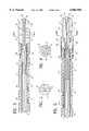
- FIG. 1is an elevational view of an intravascular device having features of the invention wherein an emitting electrode is provided on the distal end of the device for the delivery of high frequency electrical energy.
- FIG. 2is a transverse cross-sectional view of a distal portion of the intravascular device shown in FIG. 1 taken along the lines 2--2.
- FIG. 3is a longitudinal cross-sectional view of a distal portion of an alternative embodiment of the invention wherein a plurality of radially extending passageways are provided in the emitting electrode to allow for the passage of cooling fluid.
- FIG. 4is a transverse cross-sectional view of the embodiment shown in FIG. 3 taken along the lines 4--4.
- FIG. 5is a longitudinal cross-sectional view of a distal portion of another alternative embodiment of the invention wherein a plurality of longitudinally extending passageways are provided in the emitting electrode to allow for the passage of cooling fluid.
- FIG. 6is a transverse cross-sectional view of the embodiment shown in FIG. 5 taken along the lines 6--6.
- FIG. 7is an elevational view, partially in section, of another alternative embodiment of the invention wherein a portion of the emitting electrode is provided with an insulating sheath.
- FIG. 8is a transverse cross-sectional view of the catheter shown in FIG. 7 taken along the lines 8--8.
- FIG. 9is an elevational view, partially in section, of another alternative embodiment of the invention wherein a sheath is positioned on the exterior of the proximal end of the emitting electrode to direct cooling fluid onto the outside of the electrode.
- FIG. 10is a transverse cross-sectional view of the catheter shown in FIG. 9 taken along the lines 10--10.
- FIG. 11is an elevational view, partially in section, of another alternative embodiment of the invention wherein an expandable balloon is provided on one side of the distal section of the device so when it is inflated, the emitting electrode will be urged against the interior of the body lumen.
- FIG. 12is a transverse cross-sectional view of the catheter shown in FIG. 11 taken along the lines 12--12.
- FIG. 13is a longitudinal cross-sectional view of another alternative embodiment of the invention wherein the distal section of the device is provided with an emitting electrode formed of a coiled wire.
- FIG. 14is a transverse cross-sectional view of the catheter shown in FIG. 13 taken along the lines 14--14.
- FIG. 15is a longitudinal cross-sectional view of an embodiment similar to that shown in FIGS. 13 and 14 but with separate guidewire and fluid lumens.
- FIG. 16is a transverse cross-section of the catheter shown in FIG. 15 taken along the lines 16--16.
- FIG. 17is a longitudinal cross-sectional view of the distal section of another embodiment of the invention.
- FIG. 18is a transverse cross-sectional view of the embodiment shown in FIG. 17 taken along the lines 18--18.
- FIGS. 1-2schematically illustrate an embodiment of the invention wherein the elongated intravascular device 10 includes shaft 11 with a distal section 12 and a proximal section 13 and an inner lumen 14 extending within the shaft.
- the shaft 11has a braided tubular member 15 formed of a plurality of electrical conductors 16. All the strands forming the tubular member 15 need not be conductors 16, some may be formed of polymer materials such as nylon or Kevlar®.
- the distal section 12 of the shaft 11is provided with an emitting electrode 17 at the distal tip and a plurality of sensing electrodes 18 located proximal to the emitting electrode.
- the emitting electrode 17has a proximal tubular extension 19 which extends within the inner lumen 14 and is secured by suitable adhesive to the interior surface of the braided tubular member 15.
- One or more individual insulated electrical conductors 16are electrically connected by solder 20 to the emitting electrode 17.
- Individual insulated electrical conductors 16are also electrically connected to the sensing electrodes 18 by solder (not shown).
- the conductors 16extend to the proximal end of the shaft 11 where they are bundled and formed into cable 21 leading to multiple pin electrical connector 22 where each electrical conductor is connected to a separate pin (not shown).
- the proximal extremity of the conductor or conductors electrically connected to the emitting electrode 17are electrically connected through the pins to a source of high frequency electrical energy (RF or microwave) and the proximal extremities of the conductors electrically connected to sensing electrodes 18 are connected through the pins to a display system (not shown) where representations are presented on the signal received by the sensing electrodes.
- a source of high frequency electrical energyRF or microwave
- a safety wire 23extends within the wall of the shaft 11 and is secured by its distal end to the emitting electrode 17 to prevent its loss within the patient.
- the distal extremity 24 of the safety wire 23is coiled within the shaft wall proximal to the emitting electrode 17 and is bonded by suitable adhesive 25 to the proximal extension 19.
- the proximal end of the safety wiremay be secured to the a band (not shown) in the shaft 11 spaced proximal to the emitting electrode 17.
- a conventional adapter 27, which is secured to the proximal end of the shaft 11,has a central arm 28 for entry of a guidewire into the inner lumen 14 and a side arm 29 also in fluid communication with the inner lumen 14 for delivery of flushing or cooling fluid to the emitting electrode 17 on the distal section of the shaft.
- An O-ringmay be provided in the proximal hub of the central arm 28 to prevent the escape of fluid.
- FIGS. 3 an 4is essentially the same as the embodiment shown in FIGS. 1 and 2 (and is similarly numbered) except that a plurality of radially extending passageways 30 extend between the inner lumen 14 and the exterior of the electrode 17.
- FIGS. 5 and 6Another embodiment is shown in FIGS. 5 and 6 where the emitting electrode 17 has longitudinally disposed passageways 35 for directing cooling fluid from the inner lumen 14 through the electrode and out the ports 36 in the distal tip of the electrode.
- the intravascular device shownis otherwise essentially the same as the prior devices and is similarly numbered.
- a guidewire 31may be used to occlude inner lumen 14 as in the prior embodiment to ensure an adequate flow of cooling fluid through passageways 35 to maintain the temperature of the emitting electrode 17 at a desired level.
- FIGS. 7 and 8illustrate yet another embodiment of the invention wherein an arcuate insulating sheath 40 is secured about an exterior portion of the emitting electrode 17 to ensure a more focused emission of high frequency electrical energy from a smaller exposed portion of the electrode toward the tissue to be treated to control the size of the lesion formed.
- This deviceis for the most part the same as the previously discussed embodiments, except for insulation sheath 40, and is therefore similarly numbered.
- FIGS. 9 and 10Another embodiment is depicted in FIGS. 9 and 10 wherein a fluid control sheath 41 which is secured by its proximal extremity to the adhesive 25 and extends over the exterior of the emitting electrode 17.
- the inner diameter of the distal end of the sheath 41is slightly larger than the outer diameter of the electrode 17 to provide an annular gap 42 therebetween which directs cooling fluid along the exterior surface of the electrode as indicated by the arrows.
- the cooling fluidpasses from the inner lumen 14 through the ports 38 in the tubular extension 19 and through the annular gap 42.
- a guidewire 31is disposed within the inner lumen 14 with the coil 33 at least partially occluding the distal portion of the inner lumen so that an adequate flow of cooling fluid passes along the exterior of the electrode 17 to ensure sufficient cooling thereof.
- an expandable positioning membersuch as an inflatable balloon 43, which when inflated ensures contact between a desired portion of the blood vessel wall 44 and the emitting electrode 17 as shown in FIGS. 11 and 12.
- An inflation lumen 45extends through the shaft 11 from its proximal end to a location within the interior of the balloon 43.
- a three arm adapter(not shown) is secured to the proximal end of the shaft. While only one sensing electrode 18 is shown in the drawings, a plurality of sensing electrodes may be provided proximal to the balloon 43.
- the maximum transverse dimension of the balloon 43 as measured from the opposite side of the shaft 11may range from about 0.5 to about 5 mm, preferably about 1.5 to about 4 mm.
- FIGS. 13 and 14represent another embodiment where the emitting electrode 50 is a helical coil on the distal end of the shaft 11.
- the proximal end of the coil 51is secured by solder 52 to the distal end of the shaft 11 shown in FIG. 13 to facilitate an electrical connection with the conductors 16 in the shaft 11 and the distal end of the coil is secured by adhesive to the enlarged distal end 53 of the lining 54.
- Perfusion holes 55are provided in lining 54 to allow fluid passing through inner lumen 14 to contact and thus cool the coil 51.
- the inner lumen 14is disposed within the inner tubular member 60 which extends to the distal tip 61.
- Annular lumen 62extends between the interior surface of braided tubular member 15 and the exterior surface of inner tubular member 60.
- Electrode coil 63is secured by its proximal end to the shaft 11 by solder 64 and is electrically connected to a conductor of the braided tubular member 15. The distal end of the coil 63 is secured to the distal tip 61 by a suitable adhesive or by fusing the distal tip about the distal end of the coil.
- the delivery of cooling fluid through the annular lumen 62is independent of a guidewire (not shown) in lumen 14.
- FIGS. 17 and 18illustrate the distal portion of yet another embodiment of the invention where an emitting coil electrode 70 is secured to the distal tip of shaft 11 by means of adhesive or solder.
- a safety wire 71which extends through the shaft 11 as in the previous embodiments, is soldered to the distal tip of the emitting coil electrode 70.
- Sensing electrodes 18are provided on shaft 11 proximal to the emitting electrode coil 70 as in the previous embodiments. The details of shaft 11 are the same as shown in the prior embodiments.
- the overall length of the intravascular devices of the inventionmay range from about 80 to about 300 cm, typically about 120 to about 175 cm for delivery through the femoral artery or vein and about 80 to about 120 cm for delivery through the brachiocephalic artery or internal jugular vein. Because the intravascular device is to be advanced over a guidewire, the guidewire must be longer than the catheter by about 20 to about 60 cm.
- the outer diameter of the shaft of the intravascular deviceshould be less than about 0.065 inch (1.65 mm) and preferably about 0.035-0.06 inch (0.89-1.5 mm).
- the inner lumen 14has an inner diameter of about 0.01 to about 0.04 inch (0.25-1 mm) to facilitate the reception and advancement of a guidewire therethrough, which is typically about 0.010 to about 0.018 inch (0.25-0.46 mm) in outer diameter.
- the diameter of the inner lumen through the emitting electrodemay be much smaller than the diameter of the inner lumen in the more proximal portions of the shaft 11.
- the distal section 12 of the shaftis about 3 to about 20 cm in length.
- An intermediate section having an intermediate stiffnessmay be provided between the proximal section 13 and the distal section 12 with a length of about 5 to about 40 cm in length, typically about 20 cm in length.
- the radial passageways 30are typically about 0.02 inch (0.5 mm) in diameter and the longitudinal passageways 35 are typically about 0.01 inch (0.25 mm).
- the emitting electrodeis generally longer than about 2 mm.
- the lengthis generally less than about 10 mm, but for an emitting electrode in the form of helical coil the length may be about 2 to about 30 mm, preferably about 2 to about 20 mm.
- the materials of construction of the intravascular device of the inventionmay be formed of conventional materials.
- the electrical conductors 16may be electrical grade copper wire about 0.003 inch (0.08 mm) in diameter which are provided with a thin insulated jacket or coating of polyimide or other suitable insulator.
- the outer jacketmay be a thermoplastic polyurethane such as PBAX which is available from Eif Atochem Polymers of Philadelphia, Pa.
- the jacket of the proximal sectionis preferably Pebax 1147, the jacket of the intermediate section is Pebax 6333 and the jacket of the distal section is Pebax 4033.
- the sensing and emitting electrodesare preferably formed of an alloy of platinum and iridium, e.g.
- the safety wire 23may be a stainless steel wire about 0.003 inch (0.08 mm) in diameter with a polyimide coating.
- the preferred solder used to join the electrical conductors to the various electrodesis 95% Sn-5% Ag or 80% Au-20% Sn.
- One presently preferred method of using the elongated intravascular deviceincludes first advancing a guiding catheter through the patient's vascular system until the distal tip of the guiding catheter is seated within the coronary sinus ostium or the ostium of one of the coronary arteries.
- the guiding catheteris torqued by its proximal extremity which extends out of the patient to guide the distal tip into the selected ostium.
- the intravascular device of the invention with a guidewire slidably disposed within the inner lumen thereofare advanced through the guiding catheter and out the distal end thereof.
- the guidewireis first advanced into the target vein or artery and the intravascular device of the invention is advanced over the guidewire into the target blood vessel.
- the sensing electrodes 18 on the intravascular device of the inventionare used to detect electrical activity which allows the physician or operator to determine the location of the arrhythmogenic focus.
- the intravascular deviceis moved within the blood vessel, as required, to position the emitting electrode 17 as close as possible to the focus.
- High frequency electrical energypreferably in the RF range, is directed through the electrical conductors 16 connected to the emitting electrode 17 to form the desired lesion which encompasses the arrhythmogenic focus.
- Energy levels of about 5 Watts to about 100 Watts, preferably about 30 Watts to about 70 Wattsare suitable to terminate most arrhythmias.
- Typical lesions formedare about 3 mm to about 20 mm in diameter and about 3 mm to about 20 mm in length.
- an intravascular devicemay be utilized which does not have sensing electrodes.
- the guidewire utilized to advance the intravascular device of the invention into the desired blood vesselmay be provided with sensing electrodes for detecting the electrical activity of interest.
- a suitable deviceis described in copending application Ser. No. 08/188,619, filed Jan. 27, 1994, which is incorporated herein by reference.
- the electrical energy to the emitting electrodecan be controlled so as to maintain the temperature thereof.
- a thermistor or other temperature sensing devicecan be employed to monitor the electrode temperature and the temperature sensed is used to control in a conventional feedback arrangement the electrical power delivery.
Landscapes
- Health & Medical Sciences (AREA)
- Life Sciences & Earth Sciences (AREA)
- Surgery (AREA)
- Engineering & Computer Science (AREA)
- Public Health (AREA)
- Animal Behavior & Ethology (AREA)
- Veterinary Medicine (AREA)
- Physics & Mathematics (AREA)
- Biomedical Technology (AREA)
- Heart & Thoracic Surgery (AREA)
- Medical Informatics (AREA)
- Molecular Biology (AREA)
- Cardiology (AREA)
- General Health & Medical Sciences (AREA)
- Biophysics (AREA)
- Physiology (AREA)
- Pathology (AREA)
- Plasma & Fusion (AREA)
- Nuclear Medicine, Radiotherapy & Molecular Imaging (AREA)
- Otolaryngology (AREA)
- Surgical Instruments (AREA)
Abstract
Description
Claims (4)
Priority Applications (1)
| Application Number | Priority Date | Filing Date | Title |
|---|---|---|---|
| US08/944,896US6002956A (en) | 1995-05-23 | 1997-10-06 | Method of treating using an over-the-wire EP catheter |
Applications Claiming Priority (3)
| Application Number | Priority Date | Filing Date | Title |
|---|---|---|---|
| US08/447,351US5782760A (en) | 1995-05-23 | 1995-05-23 | Over-the-wire EP catheter |
| US47352595A | 1995-06-07 | 1995-06-07 | |
| US08/944,896US6002956A (en) | 1995-05-23 | 1997-10-06 | Method of treating using an over-the-wire EP catheter |
Related Parent Applications (1)
| Application Number | Title | Priority Date | Filing Date |
|---|---|---|---|
| US47352595AContinuation | 1995-05-23 | 1995-06-07 |
Publications (1)
| Publication Number | Publication Date |
|---|---|
| US6002956Atrue US6002956A (en) | 1999-12-14 |
Family
ID=27034947
Family Applications (1)
| Application Number | Title | Priority Date | Filing Date |
|---|---|---|---|
| US08/944,896Expired - LifetimeUS6002956A (en) | 1995-05-23 | 1997-10-06 | Method of treating using an over-the-wire EP catheter |
Country Status (1)
| Country | Link |
|---|---|
| US (1) | US6002956A (en) |
Cited By (38)
| Publication number | Priority date | Publication date | Assignee | Title |
|---|---|---|---|---|
| WO2000051490A1 (en)* | 1999-03-03 | 2000-09-08 | Cardiac Pacemakers, Inc. | Insertion apparatus for left ventricular access lead |
| WO2001072368A2 (en) | 2000-03-31 | 2001-10-04 | Medtronic, Inc. | Intralumenal visualization system with deflectable mechanism |
| US6366807B1 (en)* | 1995-06-06 | 2002-04-02 | Board Of Regents, The University Of Texas System | Electrode system in iontophoretic treatment devices |
| US20020173785A1 (en)* | 2000-03-31 | 2002-11-21 | Medtronic, Inc. | System and method for positioning implantable medical devices within coronary veins |
| GR1004170B (en)* | 2001-11-07 | 2003-02-26 | Χριστοδουλος Στεφαναδης | Catheter for temperature measurement of the vascular wall (artery or vein) or the wall of concave biological organs |
| US20030125619A1 (en)* | 2001-12-31 | 2003-07-03 | Cardiac Pacemakers, Inc. | Telescoping guide catheter with peel-away outer sheath |
| US6595991B2 (en)* | 2000-02-25 | 2003-07-22 | Biotronik Mess- Und Therapiegerate Gmbh & Co. Ingenieurburo Berlin | Ablation catheter for the generation of linear lesions in the myocardium |
| WO2003090832A1 (en) | 2002-04-24 | 2003-11-06 | Medtronic, Inc. | Method and system for delivering a medical electrical lead within a venous system |
| WO2003090833A1 (en) | 2002-04-25 | 2003-11-06 | Medtronic, Inc. | Method and system for delivery of a medical electrical lead within a venous system |
| US20040143258A1 (en)* | 1999-08-10 | 2004-07-22 | Biosense Webster, Inc. | Irrigation probe for ablation during open heart surgery |
| US20050090880A1 (en)* | 2002-03-20 | 2005-04-28 | Fogazzi Di Venturelli Andrea &C. S.N.C. | Catheter with flexible cooled electrode |
| US20050182387A1 (en)* | 2004-02-13 | 2005-08-18 | Cardiac Pacemakers, Inc. | Peel-away catheter shaft |
| US20050246007A1 (en)* | 2004-04-28 | 2005-11-03 | Medtronic, Inc. | Novel lead body assemblies |
| US20060095030A1 (en)* | 2004-11-04 | 2006-05-04 | Scimed Life Systems, Inc. | Preshaped ablation catheter for ablating pulmonary vein ostia within the heart |
| US7229450B1 (en)* | 2003-02-11 | 2007-06-12 | Pacesetter, Inc. | Kink resistant introducer with mapping capabilities |
| US20070179582A1 (en)* | 2006-01-31 | 2007-08-02 | Marshall Mark T | Polymer reinforced coil conductor for torque transmission |
| US7429261B2 (en) | 2004-11-24 | 2008-09-30 | Ablation Frontiers, Inc. | Atrial ablation catheter and method of use |
| US7468062B2 (en) | 2004-11-24 | 2008-12-23 | Ablation Frontiers, Inc. | Atrial ablation catheter adapted for treatment of septal wall arrhythmogenic foci and method of use |
| US20090163911A1 (en)* | 2007-12-21 | 2009-06-25 | Hong Cao | Thermally insulated irrigation catheter assembly |
| US20090171304A1 (en)* | 2007-12-31 | 2009-07-02 | Hong Cao | Coated hypodermic needle |
| US20090306649A1 (en)* | 2007-12-28 | 2009-12-10 | Mest Robert A | Irrigated catheter with improved irrigation flow |
| US20100198040A1 (en)* | 2006-06-28 | 2010-08-05 | C. R. Bard, Inc. | Methods and apparatus for assessing and improving electrode contact with cardiac tissue |
| US7850685B2 (en) | 2005-06-20 | 2010-12-14 | Medtronic Ablation Frontiers Llc | Ablation catheter |
| US7856277B1 (en)* | 2001-05-29 | 2010-12-21 | Boston Scientific Neuromodulation Corporation | Neural stimulation lead fixation |
| US7857808B2 (en) | 2002-10-25 | 2010-12-28 | The Regents Of The University Of Michigan | Ablation catheters |
| US7983766B1 (en) | 2001-05-29 | 2011-07-19 | Boston Scientific Neuromodulation Corporation | Method of securing a neural stimulation lead |
| EP2471480A1 (en)* | 2010-12-29 | 2012-07-04 | Biosense Webster (Israel), Ltd. | Braid with integrated signal conductors |
| US8295945B1 (en)* | 2001-05-29 | 2012-10-23 | Boston Scientific Neuromodulation Corporation | Neural stimulation lead fixation |
| US8486063B2 (en) | 2004-10-14 | 2013-07-16 | Medtronic Ablation Frontiers Llc | Ablation catheter |
| US8588935B2 (en) | 2010-04-14 | 2013-11-19 | Medtronic, Inc. | Implantable medical lead |
| US8617152B2 (en) | 2004-11-15 | 2013-12-31 | Medtronic Ablation Frontiers Llc | Ablation system with feedback |
| US8641704B2 (en) | 2007-05-11 | 2014-02-04 | Medtronic Ablation Frontiers Llc | Ablation therapy system and method for treating continuous atrial fibrillation |
| US8657814B2 (en) | 2005-08-22 | 2014-02-25 | Medtronic Ablation Frontiers Llc | User interface for tissue ablation system |
| US8834461B2 (en) | 2005-07-11 | 2014-09-16 | Medtronic Ablation Frontiers Llc | Low power tissue ablation system |
| US8974445B2 (en) | 2009-01-09 | 2015-03-10 | Recor Medical, Inc. | Methods and apparatus for treatment of cardiac valve insufficiency |
| US20170020501A1 (en)* | 2011-07-15 | 2017-01-26 | Cook Medical Technologies Llc | Introducer sheath with braided filament securement mechanism |
| US9700372B2 (en) | 2002-07-01 | 2017-07-11 | Recor Medical, Inc. | Intraluminal methods of ablating nerve tissue |
| US20200155229A1 (en)* | 2018-11-21 | 2020-05-21 | Tau Pnu Medical Co., Ltd. | Rf ablation catheter for treating hypertrophic cardiomyopathy and method of treating hypertrophic cardiomyopahty by using same |
Citations (22)
| Publication number | Priority date | Publication date | Assignee | Title |
|---|---|---|---|---|
| US4519403A (en)* | 1983-04-29 | 1985-05-28 | Medtronic, Inc. | Balloon lead and inflator |
| US4832048A (en)* | 1987-10-29 | 1989-05-23 | Cordis Corporation | Suction ablation catheter |
| CA2032883A1 (en)* | 1989-12-29 | 1991-06-30 | Neal E. Fearnot | Flexible, kink-resistant catheter |
| SU1690786A1 (en)* | 1989-06-30 | 1991-11-15 | Каунасский Медицинский Институт | Electrocardial electrode |
| EP0499491A2 (en)* | 1991-02-15 | 1992-08-19 | Cardiac Pathways Corporation | Endocardial mapping and ablation system and catheter probe and method |
| US5184621A (en)* | 1991-05-29 | 1993-02-09 | C. R. Bard, Inc. | Steerable guidewire having electrodes for measuring vessel cross-section and blood flow |
| US5257635A (en)* | 1988-11-25 | 1993-11-02 | Sensor Electronics, Inc. | Electrical heating catheter |
| EP0573311A1 (en)* | 1992-06-05 | 1993-12-08 | Cardiac Pathways Corporation | Endocardial mapping and ablation system utilising a separately controlled ablation catheter |
| WO1994002077A2 (en)* | 1992-07-15 | 1994-02-03 | Angelase, Inc. | Ablation catheter system |
| US5334193A (en)* | 1992-11-13 | 1994-08-02 | American Cardiac Ablation Co., Inc. | Fluid cooled ablation catheter |
| EP0609182A1 (en)* | 1993-01-18 | 1994-08-03 | X-TRODE S.r.l. | An electrode catheter for mapping and operating on cardiac cavities |
| EP0608609A2 (en)* | 1992-12-01 | 1994-08-03 | Cardiac Pathways Corporation | Catheter for RF ablation with cooled electrode and method |
| WO1994016619A1 (en)* | 1993-01-29 | 1994-08-04 | Cardima, Inc. | Method intravascular sensing devices for electrical activity |
| WO1994024931A1 (en)* | 1993-05-05 | 1994-11-10 | Arrow International Investment Corp. | Electrode-carrying catheter and method of making same |
| WO1995005771A1 (en)* | 1993-08-23 | 1995-03-02 | Webster Wilton W Jr | Steerable open-lumen catheter |
| WO1995010322A1 (en)* | 1993-10-15 | 1995-04-20 | Ep Technologies, Inc. | Creating complex lesion patterns in body tissue |
| US5517989A (en)* | 1994-04-01 | 1996-05-21 | Cardiometrics, Inc. | Guidewire assembly |
| US5545161A (en)* | 1992-12-01 | 1996-08-13 | Cardiac Pathways Corporation | Catheter for RF ablation having cooled electrode with electrically insulated sleeve |
| US5549109A (en)* | 1993-10-01 | 1996-08-27 | Target Therapeutics, Inc. | Sheathed multipolar catheter and multipolar guidewire for sensing cardiac electrical activity |
| US5575810A (en)* | 1993-10-15 | 1996-11-19 | Ep Technologies, Inc. | Composite structures and methods for ablating tissue to form complex lesion patterns in the treatment of cardiac conditions and the like |
| WO1996037146A1 (en)* | 1995-05-23 | 1996-11-28 | Cardima, Inc. | Over-the-wire ep catheter |
| US5645064A (en)* | 1992-01-29 | 1997-07-08 | Cardima, Inc. | High resolution intravascular signal detection |
- 1997
- 1997-10-06USUS08/944,896patent/US6002956A/ennot_activeExpired - Lifetime
Patent Citations (26)
| Publication number | Priority date | Publication date | Assignee | Title |
|---|---|---|---|---|
| US4519403A (en)* | 1983-04-29 | 1985-05-28 | Medtronic, Inc. | Balloon lead and inflator |
| US4832048A (en)* | 1987-10-29 | 1989-05-23 | Cordis Corporation | Suction ablation catheter |
| US5257635A (en)* | 1988-11-25 | 1993-11-02 | Sensor Electronics, Inc. | Electrical heating catheter |
| SU1690786A1 (en)* | 1989-06-30 | 1991-11-15 | Каунасский Медицинский Институт | Electrocardial electrode |
| CA2032883A1 (en)* | 1989-12-29 | 1991-06-30 | Neal E. Fearnot | Flexible, kink-resistant catheter |
| EP0499491A2 (en)* | 1991-02-15 | 1992-08-19 | Cardiac Pathways Corporation | Endocardial mapping and ablation system and catheter probe and method |
| US5184621A (en)* | 1991-05-29 | 1993-02-09 | C. R. Bard, Inc. | Steerable guidewire having electrodes for measuring vessel cross-section and blood flow |
| US5645064A (en)* | 1992-01-29 | 1997-07-08 | Cardima, Inc. | High resolution intravascular signal detection |
| EP0573311A1 (en)* | 1992-06-05 | 1993-12-08 | Cardiac Pathways Corporation | Endocardial mapping and ablation system utilising a separately controlled ablation catheter |
| US5500012A (en)* | 1992-07-15 | 1996-03-19 | Angeion Corporation | Ablation catheter system |
| WO1994002077A2 (en)* | 1992-07-15 | 1994-02-03 | Angelase, Inc. | Ablation catheter system |
| US5334193A (en)* | 1992-11-13 | 1994-08-02 | American Cardiac Ablation Co., Inc. | Fluid cooled ablation catheter |
| EP0608609A2 (en)* | 1992-12-01 | 1994-08-03 | Cardiac Pathways Corporation | Catheter for RF ablation with cooled electrode and method |
| US5545161A (en)* | 1992-12-01 | 1996-08-13 | Cardiac Pathways Corporation | Catheter for RF ablation having cooled electrode with electrically insulated sleeve |
| US5423811A (en)* | 1992-12-01 | 1995-06-13 | Cardiac Pathways Corporation | Method for RF ablation using cooled electrode |
| EP0609182A1 (en)* | 1993-01-18 | 1994-08-03 | X-TRODE S.r.l. | An electrode catheter for mapping and operating on cardiac cavities |
| US5509411A (en)* | 1993-01-29 | 1996-04-23 | Cardima, Inc. | Intravascular sensing device |
| WO1994016619A1 (en)* | 1993-01-29 | 1994-08-04 | Cardima, Inc. | Method intravascular sensing devices for electrical activity |
| WO1994016618A1 (en)* | 1993-01-29 | 1994-08-04 | Cardima, Inc. | Intravascular sensing device |
| WO1994024931A1 (en)* | 1993-05-05 | 1994-11-10 | Arrow International Investment Corp. | Electrode-carrying catheter and method of making same |
| WO1995005771A1 (en)* | 1993-08-23 | 1995-03-02 | Webster Wilton W Jr | Steerable open-lumen catheter |
| US5549109A (en)* | 1993-10-01 | 1996-08-27 | Target Therapeutics, Inc. | Sheathed multipolar catheter and multipolar guidewire for sensing cardiac electrical activity |
| WO1995010322A1 (en)* | 1993-10-15 | 1995-04-20 | Ep Technologies, Inc. | Creating complex lesion patterns in body tissue |
| US5575810A (en)* | 1993-10-15 | 1996-11-19 | Ep Technologies, Inc. | Composite structures and methods for ablating tissue to form complex lesion patterns in the treatment of cardiac conditions and the like |
| US5517989A (en)* | 1994-04-01 | 1996-05-21 | Cardiometrics, Inc. | Guidewire assembly |
| WO1996037146A1 (en)* | 1995-05-23 | 1996-11-28 | Cardima, Inc. | Over-the-wire ep catheter |
Non-Patent Citations (2)
| Title |
|---|
| Weston et al, "A Prototype Coronary Electrode . . . Recording", American Journal of Cardiology, vol. 70, Dec. 1, 1992. |
| Weston et al, A Prototype Coronary Electrode . . . Recording , American Journal of Cardiology, vol. 70, Dec. 1, 1992.* |
Cited By (84)
| Publication number | Priority date | Publication date | Assignee | Title |
|---|---|---|---|---|
| US6366807B1 (en)* | 1995-06-06 | 2002-04-02 | Board Of Regents, The University Of Texas System | Electrode system in iontophoretic treatment devices |
| US6122552A (en)* | 1999-03-03 | 2000-09-19 | Cardiac Pacemakers, Inc. | Insertion apparatus for left ventricular access lead |
| WO2000051490A1 (en)* | 1999-03-03 | 2000-09-08 | Cardiac Pacemakers, Inc. | Insertion apparatus for left ventricular access lead |
| US20040143258A1 (en)* | 1999-08-10 | 2004-07-22 | Biosense Webster, Inc. | Irrigation probe for ablation during open heart surgery |
| US7764994B2 (en) | 1999-08-10 | 2010-07-27 | Biosense Webster, Inc. | Irrigation probe for ablation during open heart surgery |
| US7761148B2 (en) | 1999-08-10 | 2010-07-20 | Biosense Webster, Inc. | Irrigation probe for ablation during open heart surgery |
| US8160693B2 (en) | 1999-08-10 | 2012-04-17 | Biosense Webster, Inc. | Irrigation probe for ablation during open heart surgery |
| US6852120B1 (en)* | 1999-08-10 | 2005-02-08 | Biosense Webster, Inc | Irrigation probe for ablation during open heart surgery |
| US20040153134A1 (en)* | 1999-08-10 | 2004-08-05 | Fuimaono Kristine B. | Irrigation probe for ablation during open heart surgery |
| US6595991B2 (en)* | 2000-02-25 | 2003-07-22 | Biotronik Mess- Und Therapiegerate Gmbh & Co. Ingenieurburo Berlin | Ablation catheter for the generation of linear lesions in the myocardium |
| US7497844B2 (en) | 2000-03-31 | 2009-03-03 | Medtronic, Inc. | System and method for positioning implantable medical devices within coronary veins |
| US8734397B2 (en) | 2000-03-31 | 2014-05-27 | Medtronic, Inc. | System and method for positioning implantable medical devices within coronary veins |
| US6743227B2 (en) | 2000-03-31 | 2004-06-01 | Medtronic, Inc. | Intraluminal visualization system with deflectable mechanism |
| US6733500B2 (en) | 2000-03-31 | 2004-05-11 | Medtronic, Inc. | Method and system for delivering a medical electrical lead within a venous system |
| US10328243B2 (en) | 2000-03-31 | 2019-06-25 | Medtronic, Inc. | System and method for positioning implantable medical devices within coronary veins |
| US6836687B2 (en) | 2000-03-31 | 2004-12-28 | Medtronic, Inc. | Method and system for delivery of a medical electrical lead within a venous system |
| US20020173785A1 (en)* | 2000-03-31 | 2002-11-21 | Medtronic, Inc. | System and method for positioning implantable medical devices within coronary veins |
| US20090131873A1 (en)* | 2000-03-31 | 2009-05-21 | Medtronic, Inc. | System and method for positioning implantable medical devices within coronary veins |
| WO2001072368A2 (en) | 2000-03-31 | 2001-10-04 | Medtronic, Inc. | Intralumenal visualization system with deflectable mechanism |
| US7983766B1 (en) | 2001-05-29 | 2011-07-19 | Boston Scientific Neuromodulation Corporation | Method of securing a neural stimulation lead |
| US8295945B1 (en)* | 2001-05-29 | 2012-10-23 | Boston Scientific Neuromodulation Corporation | Neural stimulation lead fixation |
| US8554342B2 (en) | 2001-05-29 | 2013-10-08 | Boston Scientific Neuromodulation Corporation | Neural stimulation lead fixation |
| US7856277B1 (en)* | 2001-05-29 | 2010-12-21 | Boston Scientific Neuromodulation Corporation | Neural stimulation lead fixation |
| WO2003039619A3 (en)* | 2001-11-07 | 2003-09-12 | Christodoulos Stefanadis | Catheter and process for the temperature measurement of the vascular wall |
| GR1004170B (en)* | 2001-11-07 | 2003-02-26 | Χριστοδουλος Στεφαναδης | Catheter for temperature measurement of the vascular wall (artery or vein) or the wall of concave biological organs |
| US6979319B2 (en)* | 2001-12-31 | 2005-12-27 | Cardiac Pacemakers, Inc. | Telescoping guide catheter with peel-away outer sheath |
| US7697996B2 (en) | 2001-12-31 | 2010-04-13 | Cardiac Pacemakers, Inc. | Telescoping guide catheter with peel-away outer sheath |
| US20070021812A1 (en)* | 2001-12-31 | 2007-01-25 | Cardiac Pacemakers, Inc. | Telescoping guide catheter with peel-away outer sheath |
| US7117039B2 (en) | 2001-12-31 | 2006-10-03 | Cardiac Pacemakers, Inc. | Methods of using a telescoping guide catheter with peel-away outer sheath |
| US20030125619A1 (en)* | 2001-12-31 | 2003-07-03 | Cardiac Pacemakers, Inc. | Telescoping guide catheter with peel-away outer sheath |
| US20100198194A1 (en)* | 2001-12-31 | 2010-08-05 | Manning Frank E | Telescoping Guide Catheter with Peel-Away Outer Sheath |
| US20050065561A1 (en)* | 2001-12-31 | 2005-03-24 | Cardiac Pacemakers, Inc. | Methods of using a telescoping guide catheter with peel-away outer sheath |
| US8126570B2 (en) | 2001-12-31 | 2012-02-28 | Cardiac Pacemakers, Inc. | Telescoping guide catheter with peel-away outer sheath |
| US7264619B2 (en)* | 2002-03-20 | 2007-09-04 | Fogazzi Di Venturelli Andrea & C. S.N.C. | Catheter with flexible cooled electrode |
| US20050090880A1 (en)* | 2002-03-20 | 2005-04-28 | Fogazzi Di Venturelli Andrea &C. S.N.C. | Catheter with flexible cooled electrode |
| WO2003090832A1 (en) | 2002-04-24 | 2003-11-06 | Medtronic, Inc. | Method and system for delivering a medical electrical lead within a venous system |
| WO2003090833A1 (en) | 2002-04-25 | 2003-11-06 | Medtronic, Inc. | Method and system for delivery of a medical electrical lead within a venous system |
| US9700372B2 (en) | 2002-07-01 | 2017-07-11 | Recor Medical, Inc. | Intraluminal methods of ablating nerve tissue |
| US9707034B2 (en) | 2002-07-01 | 2017-07-18 | Recor Medical, Inc. | Intraluminal method and apparatus for ablating nerve tissue |
| US7993333B2 (en) | 2002-10-25 | 2011-08-09 | The Regents Of The University Of Michigan | Ablation catheters |
| US7857808B2 (en) | 2002-10-25 | 2010-12-28 | The Regents Of The University Of Michigan | Ablation catheters |
| US7229450B1 (en)* | 2003-02-11 | 2007-06-12 | Pacesetter, Inc. | Kink resistant introducer with mapping capabilities |
| US20050182387A1 (en)* | 2004-02-13 | 2005-08-18 | Cardiac Pacemakers, Inc. | Peel-away catheter shaft |
| US20050246007A1 (en)* | 2004-04-28 | 2005-11-03 | Medtronic, Inc. | Novel lead body assemblies |
| US9642675B2 (en) | 2004-10-14 | 2017-05-09 | Medtronic Ablation Frontiers Llc | Ablation catheter |
| US8486063B2 (en) | 2004-10-14 | 2013-07-16 | Medtronic Ablation Frontiers Llc | Ablation catheter |
| US20060095030A1 (en)* | 2004-11-04 | 2006-05-04 | Scimed Life Systems, Inc. | Preshaped ablation catheter for ablating pulmonary vein ostia within the heart |
| US8617152B2 (en) | 2004-11-15 | 2013-12-31 | Medtronic Ablation Frontiers Llc | Ablation system with feedback |
| US9005194B2 (en) | 2004-11-24 | 2015-04-14 | Medtronic Ablation Frontiers Llc | Atrial ablation catheter adapted for treatment of septal wall arrhythmogenic foci and method of use |
| US7429261B2 (en) | 2004-11-24 | 2008-09-30 | Ablation Frontiers, Inc. | Atrial ablation catheter and method of use |
| US8273084B2 (en) | 2004-11-24 | 2012-09-25 | Medtronic Ablation Frontiers Llc | Atrial ablation catheter and method of use |
| US7468062B2 (en) | 2004-11-24 | 2008-12-23 | Ablation Frontiers, Inc. | Atrial ablation catheter adapted for treatment of septal wall arrhythmogenic foci and method of use |
| US9468495B2 (en) | 2005-06-20 | 2016-10-18 | Medtronic Ablation Frontiers Llc | Ablation catheter |
| US8979841B2 (en) | 2005-06-20 | 2015-03-17 | Medtronic Ablation Frontiers Llc | Ablation catheter |
| US8771267B2 (en) | 2005-06-20 | 2014-07-08 | Medtronic Ablation Frontiers Llc | Ablation catheter |
| US8337492B2 (en) | 2005-06-20 | 2012-12-25 | Medtronic Ablation Frontiers Llc | Ablation catheter |
| US7850685B2 (en) | 2005-06-20 | 2010-12-14 | Medtronic Ablation Frontiers Llc | Ablation catheter |
| US9566113B2 (en) | 2005-07-11 | 2017-02-14 | Medtronic Ablation Frontiers Llc | Low power tissue ablation system |
| US8834461B2 (en) | 2005-07-11 | 2014-09-16 | Medtronic Ablation Frontiers Llc | Low power tissue ablation system |
| US8657814B2 (en) | 2005-08-22 | 2014-02-25 | Medtronic Ablation Frontiers Llc | User interface for tissue ablation system |
| US20070179582A1 (en)* | 2006-01-31 | 2007-08-02 | Marshall Mark T | Polymer reinforced coil conductor for torque transmission |
| US20100198040A1 (en)* | 2006-06-28 | 2010-08-05 | C. R. Bard, Inc. | Methods and apparatus for assessing and improving electrode contact with cardiac tissue |
| US8504132B2 (en) | 2006-06-28 | 2013-08-06 | Paul Friedman | Methods and apparatus for assessing and improving electrode contact with cardiac tissue |
| EP2038002A4 (en)* | 2006-06-28 | 2010-12-29 | Bard Inc C R | METHODS AND APPARATUS FOR ASSESSING AND ENHANCING ELECTRODE CONTACT WITH CARDIAC TISSUE |
| US8641704B2 (en) | 2007-05-11 | 2014-02-04 | Medtronic Ablation Frontiers Llc | Ablation therapy system and method for treating continuous atrial fibrillation |
| US10219857B2 (en) | 2007-05-11 | 2019-03-05 | Medtronic Ablation Frontiers Llc | RF energy delivery system |
| US8771269B2 (en) | 2007-05-11 | 2014-07-08 | Medtronic Ablation Frontiers Llc | RF energy delivery system and method |
| US8221409B2 (en)* | 2007-12-21 | 2012-07-17 | St. Jude Medical, Atrial Fibrillation Division, Inc. | Thermally insulated irrigation catheter assembly |
| US20090163911A1 (en)* | 2007-12-21 | 2009-06-25 | Hong Cao | Thermally insulated irrigation catheter assembly |
| US20090306649A1 (en)* | 2007-12-28 | 2009-12-10 | Mest Robert A | Irrigated catheter with improved irrigation flow |
| US8333762B2 (en) | 2007-12-28 | 2012-12-18 | Biosense Webster, Inc. | Irrigated catheter with improved irrigation flow |
| US8255035B2 (en)* | 2007-12-31 | 2012-08-28 | St. Jude Medical, Atrial Fibrillation Division, Inc. | Coated hypodermic needle |
| US20090171304A1 (en)* | 2007-12-31 | 2009-07-02 | Hong Cao | Coated hypodermic needle |
| US8974445B2 (en) | 2009-01-09 | 2015-03-10 | Recor Medical, Inc. | Methods and apparatus for treatment of cardiac valve insufficiency |
| US8588935B2 (en) | 2010-04-14 | 2013-11-19 | Medtronic, Inc. | Implantable medical lead |
| AU2011265497B2 (en)* | 2010-12-29 | 2015-02-26 | Biosense Webster (Israel), Ltd. | Braid with integrated signal conductors |
| EP2471480A1 (en)* | 2010-12-29 | 2012-07-04 | Biosense Webster (Israel), Ltd. | Braid with integrated signal conductors |
| US9717553B2 (en) | 2010-12-29 | 2017-08-01 | Biosence Webster (Israel) Ltd. | Braid with integrated signal conductors |
| CN102551672A (en)* | 2010-12-29 | 2012-07-11 | 韦伯斯特生物官能(以色列)有限公司 | Braid with integrated signal conductors |
| CN102551672B (en)* | 2010-12-29 | 2016-08-10 | 韦伯斯特生物官能(以色列)有限公司 | There is the fabric of integration signal conductor |
| US20170020501A1 (en)* | 2011-07-15 | 2017-01-26 | Cook Medical Technologies Llc | Introducer sheath with braided filament securement mechanism |
| US10433824B2 (en)* | 2011-07-15 | 2019-10-08 | Cook Medical Technologies Llc | Introducer sheath with braided filament securement mechanism |
| US20200155229A1 (en)* | 2018-11-21 | 2020-05-21 | Tau Pnu Medical Co., Ltd. | Rf ablation catheter for treating hypertrophic cardiomyopathy and method of treating hypertrophic cardiomyopahty by using same |
| US12279810B2 (en) | 2018-11-21 | 2025-04-22 | Tau Medical Inc. | RF ablation catheter for treating hypertrophic cardiomyopathy and method of treating hypertrophic cardiomyopahty by using same |
Similar Documents
| Publication | Publication Date | Title |
|---|---|---|
| US6002956A (en) | Method of treating using an over-the-wire EP catheter | |
| US5782760A (en) | Over-the-wire EP catheter | |
| US5895355A (en) | Over-the-wire EP catheter | |
| WO1998038912A9 (en) | Over-the-wire ep catheter | |
| US6251107B1 (en) | Ep catheter | |
| US5957842A (en) | High resolution intravascular signal detection | |
| US6063077A (en) | Linear ablation device and assembly | |
| US5766152A (en) | Intraluminal delivery of tissue lysing medium | |
| US8951247B2 (en) | Methods and apparatus for forming cardiac lesions and assessing lesion quality | |
| US6972016B2 (en) | Helically shaped electrophysiology catheter | |
| US6120499A (en) | Intravascular RF occlusion catheter | |
| US20040187875A1 (en) | Method and apparatus for altering conduction properties along pathways in the heart and in vessels in conductive communication with the heart. | |
| US6113584A (en) | Intraluminal delivery of tissue lysing medium |
Legal Events
| Date | Code | Title | Description |
|---|---|---|---|
| AS | Assignment | Owner name:TRANSAMERICA BUSINESS CREDIT CORP., CONNECTICUT Free format text:ASSIGNMENT OF ASSIGNORS INTEREST;ASSIGNOR:CARDIMA, INC.;REEL/FRAME:009392/0236 Effective date:19980619 | |
| STCF | Information on status: patent grant | Free format text:PATENTED CASE | |
| FPAY | Fee payment | Year of fee payment:4 | |
| AS | Assignment | Owner name:AGILITY CAPITAL LLC, CALIFORNIA Free format text:INTELLECTUAL PROPERTY SECURITY AGREEMENT;ASSIGNOR:CARDIMA, INC.;REEL/FRAME:016050/0334 Effective date:20050523 | |
| AS | Assignment | Owner name:CARDIMA, INC., CALIFORNIA Free format text:TERMINATION OF PATENT AND TRADEMARK SECURITY AGREEMENT;ASSIGNOR:TRANSAMERICA BUSINESS CREDIT CORPORATION;REEL/FRAME:016050/0849 Effective date:20001208 | |
| AS | Assignment | Owner name:CARDIMA, INC., CALIFORNIA Free format text:TERMINATION OF PATENT SECURITY INTEREST;ASSIGNOR:AGILITY CAPITAL, LLC;REEL/FRAME:016397/0200 Effective date:20050812 | |
| FPAY | Fee payment | Year of fee payment:8 | |
| FEPP | Fee payment procedure | Free format text:PAYER NUMBER DE-ASSIGNED (ORIGINAL EVENT CODE: RMPN); ENTITY STATUS OF PATENT OWNER: SMALL ENTITY Free format text:PAYOR NUMBER ASSIGNED (ORIGINAL EVENT CODE: ASPN); ENTITY STATUS OF PATENT OWNER: SMALL ENTITY | |
| AS | Assignment | Owner name:RUI XING LIMITED, HONG KONG Free format text:ASSIGNMENT OF ASSIGNORS INTEREST;ASSIGNOR:CARDIMA, INC.;REEL/FRAME:026287/0523 Effective date:20110331 | |
| FPAY | Fee payment | Year of fee payment:12 | |
| AS | Assignment | Owner name:SICHUAN JINJIANG ELECTRONIC SCIENCE AND TECHNOLOGY Free format text:ASSIGNMENT OF ASSIGNORS INTEREST;ASSIGNOR:RUI XING LTD.;REEL/FRAME:031011/0955 Effective date:20130809 |