US6002603A - Balanced boost/buck DC to DC converter - Google Patents
Balanced boost/buck DC to DC converterDownload PDFInfo
- Publication number
- US6002603A US6002603AUS09/257,443US25744399AUS6002603AUS 6002603 AUS6002603 AUS 6002603AUS 25744399 AUS25744399 AUS 25744399AUS 6002603 AUS6002603 AUS 6002603A
- Authority
- US
- United States
- Prior art keywords
- converter
- pair
- input
- switch
- output
- Prior art date
- Legal status (The legal status is an assumption and is not a legal conclusion. Google has not performed a legal analysis and makes no representation as to the accuracy of the status listed.)
- Expired - Fee Related
Links
- 239000003990capacitorSubstances0.000claimsabstractdescription54
- 230000007423decreaseEffects0.000claimsabstractdescription18
- 238000010586diagramMethods0.000description5
- 230000007935neutral effectEffects0.000description4
- 230000004075alterationEffects0.000description2
- 230000001276controlling effectEffects0.000description2
- 238000001914filtrationMethods0.000description2
- 230000004048modificationEffects0.000description2
- 238000012986modificationMethods0.000description2
- 230000001105regulatory effectEffects0.000description2
- 230000008901benefitEffects0.000description1
- 230000009467reductionEffects0.000description1
- 230000004044responseEffects0.000description1
Images


Classifications
- H—ELECTRICITY
- H02—GENERATION; CONVERSION OR DISTRIBUTION OF ELECTRIC POWER
- H02M—APPARATUS FOR CONVERSION BETWEEN AC AND AC, BETWEEN AC AND DC, OR BETWEEN DC AND DC, AND FOR USE WITH MAINS OR SIMILAR POWER SUPPLY SYSTEMS; CONVERSION OF DC OR AC INPUT POWER INTO SURGE OUTPUT POWER; CONTROL OR REGULATION THEREOF
- H02M3/00—Conversion of DC power input into DC power output
- H02M3/02—Conversion of DC power input into DC power output without intermediate conversion into AC
- H02M3/04—Conversion of DC power input into DC power output without intermediate conversion into AC by static converters
- H02M3/10—Conversion of DC power input into DC power output without intermediate conversion into AC by static converters using discharge tubes with control electrode or semiconductor devices with control electrode
- H02M3/145—Conversion of DC power input into DC power output without intermediate conversion into AC by static converters using discharge tubes with control electrode or semiconductor devices with control electrode using devices of a triode or transistor type requiring continuous application of a control signal
- H02M3/155—Conversion of DC power input into DC power output without intermediate conversion into AC by static converters using discharge tubes with control electrode or semiconductor devices with control electrode using devices of a triode or transistor type requiring continuous application of a control signal using semiconductor devices only
- H02M3/156—Conversion of DC power input into DC power output without intermediate conversion into AC by static converters using discharge tubes with control electrode or semiconductor devices with control electrode using devices of a triode or transistor type requiring continuous application of a control signal using semiconductor devices only with automatic control of output voltage or current, e.g. switching regulators
- H02M3/158—Conversion of DC power input into DC power output without intermediate conversion into AC by static converters using discharge tubes with control electrode or semiconductor devices with control electrode using devices of a triode or transistor type requiring continuous application of a control signal using semiconductor devices only with automatic control of output voltage or current, e.g. switching regulators including plural semiconductor devices as final control devices for a single load
Definitions
- the present inventionrelates to power converters, and more particularly, to DC to DC converters.
- Turbine generator systemsoften include a gas powered turbine to provide motive force to an alternator which provides single phase or polyphase AC power to a load.
- the alternatorcan be driven as a motor to provide motive force to the turbine until it is running at a self-sustaining, operational speed.
- a power inverter system electrically connected between the batteries and the alternatoris utilized to increase the potential of the DC voltage and to convert the increased potential DC voltage into an AC voltage for use by the alternator.
- the power inverter systemincludes a DC to DC converter to increase the DC voltage of the batteries and a DC to AC power inverter to convert the increased DC voltage into an AC voltage usable by the alternator.
- a problem with prior art power inverter systemsis that the ground potential of the batteries can float such that when the turbine generator is operating, a large potential difference can exist between the batteries and electrical components of the power inverter system. This large potential difference requires that instrumentation connected between the chassis and the electrical components of the power inverter system be isolated from ground potentials that can achieve 1000 volts DC or more.
- neutrallow impedance electrical voltage reference
- a DC to DC converterhaving an inductor and a first transistor having a first power terminal connectable to one side of a DC power supply and a second power terminal connected to one end of the inductor.
- a second transistorhas a first terminal connected to the other end of the inductor and a second power terminal connected to another side of the DC power supply.
- a pair of capacitorsis connected in series and defines a node therebetween which is connected to a ground potential.
- a third transistorhas a first power terminal connected to one end of the inductor and a second power terminal connected to one end of the pair of capacitors.
- a fourth transistorhas a first power terminal connected to the other end of the pair of capacitors and a second power terminal connected to the other end of the inductor.
- a controlleris connected to a control terminal of each transistor for controlling the switching thereof.
- the ground potentialcan be connected to the second power terminal of the second transistor or to a node between a pair of series connected batteries of the DC power supply.
- the inductorcan include a pair of inductors connected in series and defining a node therebetween which is connected to the ground potential.
- Each transistorcan include a diode connected between the first power terminal and the second power terminal thereof. Each diode is oriented to conduct current in a direction opposite its corresponding transistor.
- I have also invented a DC to DC converterhaving a first switch and a second switch connected in series between a first input/output of the converter and a second input/output of the converter.
- the first switch and the second switchdefine therebetween a first node.
- a third switch and a fourth switchare connected in series between the first input/output of the converter and the second input/output of the converter.
- the third switch and the fourth switchdefine therebetween a second node.
- An inductoris connected between the first node and the second node.
- a pair of capacitorsis connected in series across the second input/output of the converter.
- the pair of capacitorsdefines a third node therebetween which is connected to a ground potential.
- a controlleris connected to control the switching of at least one of the switches.
- the ground potentialcan be connected to an end of the series connected third and fourth switches at the first input/output of the converter.
- the inductorcan include a pair of inductors connected in series and defining a node therebetween which is connected to the ground potential.
- the first input/output of the convertercan be connected to a DC voltage source and the ground reference can be electrically referenced between a positive terminal and a negative terminal of the DC voltage source.
- the DC voltage sourcecan include a pair of DC voltage sources connected in series and the ground potential can be connected between the pair of DC voltage sources.
- a diodecan be connected in parallel with each switch so that during operation of the converter each switch conducts current in one direction and the diode connected in parallel with each switch conducts current in an opposite direction.
- the DC to DC convertercan include a DC to DC converter/regulator having an input and an output.
- the inputcan be connected to the second input/output of the converter.
- the converter/regulatorincludes a first pair of diodes connected in series to conduct current from the output to the input which is connected to the end of the series connected third switch and fourth switch at the second input/output of the converter.
- the first pair of diodesdefines therebetween a fourth node.
- a second pair of diodesis connected in series to conduct current from the input which is connected to an end of the series connected first switch and second switch at the second input/output of the converter to the output.
- the second pair of diodesdefines therebetween a fifth node.
- a pair of inductorsis connected in series between the fourth node and the fifth node.
- the pair of inductorsdefines therebetween a sixth node which is connected to the ground potential.
- a pair of capacitorsis connected in series across the output.
- the pair of capacitorsdefines therebetween a seventh node which is connected to the ground potential.
- a fifth switchis connected in parallel with one of the diodes of the first pair of diodes adjacent the input and a sixth switch is connected in parallel with one of the diodes of the second pair of diodes adjacent the input.
- the fifth switchconducts current in one direction and the diode connected in parallel with the fifth switch conducts current in an opposite direction and the sixth switch conducts current in one direction and the diode in parallel with the sixth switch conducts current in an opposite direction.
- a DC to DC converterhaving a first pair of diodes connected in series and defining therebetween a first node.
- the first pair of diodesis connected to conduct current from a first input/output of the converter to a second input/output of the converter.
- a second pair of diodesis connected in series and defines therebetween a second node.
- the second pair of diodesis connected to conduct current from the second input/output of the converter to the first input/output of the converter.
- a pair of inductorsis connected in series between the first node and the second node.
- the pair of inductorsdefines therebetween a third node which is connected to a reference ground.
- a pair of capacitorsis connected in series across the second input/output of the converter.
- the pair of capacitorsdefines therebetween a fourth node which is connected to the reference ground.
- a first switchis connected in parallel with one diode of the first pair of diodes adjacent the first input/output of the converter.
- a second switchis connected in parallel with one diode of the second pair of diodes adjacent the first input/output of the converter.
- a controllercontrols the switching of the switches so that during operation of the converter, the first and second switches are controlled to conduct current between the first input/output of the converter and the pair of inductors.
- the first input/outputcan be connected to a DC voltage source having a positive terminal and a negative terminal.
- the reference groundcan be electrically referenced between the positive terminal and the negative terminal of the DC voltage source.
- a third switchcan be connected in parallel with the other diode of the first pair of diodes adjacent the second input/output of the converter and a fourth switch can be connected in parallel with the other diode of the second pair of diodes adjacent the second input/output of the converter.
- the third and fourth switchesare controlled to conduct between the pair of inductors and the second input/output of the converter.
- the controllercontrols the switching of the switches so that the first and second switches conduct current simultaneously, the third and fourth switches conduct current simultaneously, and the first and second switches conduct current when the third and fourth switches block current, and vice versa.
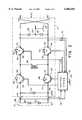
- FIG. 1is a schematic diagram of a power inverter system which includes a DC to DC converter and a DC to three-phase inverter/rectifier for converting DC power to AC power, and vice versa;
- FIG. 2is an electric circuit diagram of the DC to DC converter of the power inverter system shown in FIG. 1;
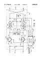
- FIG. 3is a modified electric circuit diagram of the DC to DC converter shown in FIG. 2;
- FIG. 4is a schematic diagram of the power inverter system shown in FIG. 1 including a DC to DC converter/regulator connected between the DC to DC converter and the DC to three-phase inverter/rectifier; and
- FIG. 5is an electric circuit diagram of the DC to DC converter/regulator shown in FIG. 4.
- a typical turbine/generator system 2includes a turbine 4 which supplies motive force to a three-phase alternator 6 in a manner known in the art.
- the three-phase alternator 6In response to motive force being supplied thereto from the turbine 4, the three-phase alternator 6 generates three-phase electrical power which is supplied to a load 8.
- the power inverter system 12includes a DC to DC converter 14, a DC to three-phase inverter/rectifier 16 and a control system 18.
- the DC to DC converter 14includes a first input/output 20 connected to the DC power supply 10 and a second input/output 22 connected to a first input/output 24 of the DC to three-phase inverter/rectifier 16.
- the DC to three-phase inverter/rectifier 16has a second input/output connected to the three-phase alternator 6.
- the inverter system 12converts DC voltage received at the first input/output 20 of the DC to DC converter 14 into three-phase AC voltage at the second input/output 26 of the DC to three-phase inverter/rectifier 16.
- the inverter system 12terminates supplying three-phase power to the three-phase alternator 6.
- the inverter system 12converts three-phase AC power received from the three-phase alternator 6 at the second input/output 26 of the DC to three-phase inverter/rectifier 16 into DC power at the first input/output 20 of the DC to DC converter 14.
- the DC power generated at the first input/output 20 of the DC to DC converter 14is utilized to charge the DC power supply 10, which includes one or more batteries that are utilized to supply power to the power inverter system 12 when the three-phase alternator 6 is utilized as a motor to provide motive force to the turbine 4 during start-up.
- the DC power supply 10has a positive terminal 28 and a negative terminal 30 connected to the first input/output 20 of the DC to DC converter 14.
- the DC to DC converter 14has a first transistor 32 having a collector or first power terminal 34 connected to the positive terminal 28 of the DC power supply 10 and an emitter or second power terminal 36 connected to one side of an inductor 38.
- a second transistor 40has a collector or first power terminal 42 connected to a side of the inductor 38 opposite the emitter terminal 36 of the first transistor 32 and an emitter or second power terminal 44 which is connected to the negative terminal 30 of the DC power supply 10.
- the negative terminal 30 of the DC power supply 10 and the emitter terminal 44 of the second transistor 40are connected to a ground potential or reference ground 46.
- a third transistor 48has a collector or first power terminal 50 and an emitter or second power terminal 52.
- the collector terminal 50 of the third transistor 48is connected to the emitter terminal 36 of the first transistor 32.
- a fourth transistor 54has a collector or first power terminal 56 and an emitter or second power terminal 58.
- the emitter terminal 58 of the fourth transistor 54is connected to the collector terminal 42 of the second transistor 40.
- a pair of capacitors 60 and 62is connected in series between the emitter terminal 52 of the third transistor 48 and the collector terminal 56 of the fourth transistor 54.
- the capacitors 60 and 62define a node 64 therebetween which is connected to the ground potential or reference ground 46.
- Diodes 66, 68, 70 and 72are connected between the emitter terminals and the collector terminals of transistors 32, 40, 48 and 54 to conduct current in a direction opposite transistors 32, 40, 48 and 54, respectively.
- the control system 18is connected to the base or control terminal of each transistor 32, 40, 48 and 54 to control the switching ON and OFF thereof.
- the control systemis also connected to the ground potential or reference ground 46.
- the control system 18causes the first and second transistors 32 and 40 to switch ON thereby creating a current path from the DC power supply 10 through the inductor 38.
- the control system 18causes the first and second transistors 32 and 40 to switch OFF.
- the current flowing through the inductor 38 when the first and second transistors 32 and 40 switch OFFflows through diodes 70 and 72 and capacitors 60 and 62 thereby charging capacitors 60 and 62.
- the control system 18causes the first and second transistors 32 and 40 to switch ON thereby creating the current path between the DC power supply 10 and the inductor 38.
- the control system 18repeats switching the first and second transistors 32 and 40 OFF and ON when the current through the inductor 38 increases and decreases to a sufficient extent, respectively, to maintain a charge, and hence the voltage, in the capacitors 60 and 62 at a desired level when the DC to three-phase inverter/rectifier 16 supplies power to the three-phase alternator 6 operating as a motor during start-up of the turbine 4.
- the control system 18causes the third and fourth transistors 48 and 54 to remain switched OFF.
- a rectifier of the DC to three-phase inverter/rectifier 16converts three-phase AC voltage received at the second input/output 26 thereof into a rectified DC voltage at the first input/output 24 thereof.
- the control system 18causes the DC to DC converter 14 to convert the rectified DC voltage received at the second input/output 22 thereof into a regulated DC voltage at the first input/output 20 thereof.
- the DC voltage generated by the DC to DC converter 14 at the first input/output 20 thereofis utilized to charge batteries or other storage elements of the DC power supply 10.
- the control system 18causes the third and fourth transistors 48 and 54 to switch ON thereby creating a current path between the second input/output 22 and the inductor 38.
- the control system 18causes the third and fourth transistors 48 and 54 to switch OFF.
- the current flowing through the inductor 38 when the third and fourth transistors 48 and 54 switch OFFflows through diodes 66 and 68 and the DC power supply 10 thereby charging the DC power supply 10.
- the control system 18causes the third and fourth transistors 48 and 54 to switch ON thereby creating the current path between the second input/output 22 and the inductor 38. Thereafter, the control system 18 repeats switching the third and fourth transistors 48 and 54 OFF and ON when the current through the inductor 38 increases and decreases to a sufficient extent, respectively, to maintain the voltage at the first input/output 20 at a desired level for charging the DC power supply 10.
- the control systemcauses the first and second transistors 32 and 40 to remain switched OFF.
- the DC to DC converter 14includes a capacitor 74 connected between the collector terminal 34 of the first transistor 32 and the emitter terminal 44 of the second transistor 40 for filtering AC signals coupled between the DC power supply 10 and the first input/output 20 of the DC to DC converter 14.
- Voltage sense leads 76can be connected between the control system 18 and the second input/output 22 of the DC to DC converter 14, and voltage sense leads 78 can be connected between the control system 18 and the first input/output 20 of the DC to DC converter 14.
- the voltage sense leads 76 and 78enable the control system 18 to measure the voltage across the capacitors 60 and 62 and the DC power supply 10, respectively.
- the control system 18can control the switching of the first and second transistors 32 and 40 to generate a desired DC voltage at the second input/output 22 of the DC to DC converter 14, and can control the switching of the third and fourth transistors 48 and 54 to generate a desired DC voltage at the first input/output 20 of the DC to DC converter 14.
- the DC power supply 10includes batteries 80 and 82 connected in series between the positive terminal 28 and the negative terminal 30 thereof.
- FIG. 3A variation of the DC to DC converter 14 of FIG. 2 is shown in FIG. 3, where like reference numbers correspond to like elements.
- the inductor 38includes a pair of inductors 84 and 86 connected in series and defining a node 88 therebetween.
- the node 88is connected to the ground potential or reference ground 46.
- the ground potential 46is also connected to a node 90 between batteries 80 and 82, not to the negative terminal 30 of the DC power supply 10 as shown in FIG. 2.
- the three-phase alternator 6can utilize a shaft position sensor for feedback to the control system 18 for both speed and position sensing, thus avoiding the need for separate shaft positioning and speed systems with a corresponding reduction in cost and complexity.
- the DC power supply 10 and the second input/output 22 of the DC to DC converter 14are referenced to the same ground potential or reference ground 46, large potential differences between the DC power supply 10 and the node 64 are avoided.
- a DC to DC converter/regulator 100can be connected between the second input/output 22 of the DC to DC converter 14 and the first input/output 24 of the DC to three-phase inverter/rectifier 16 to regulate the voltage supplied to the first input/output 24 of the DC to three-phase inverter/rectifier 16.
- the DC to DC converter/regulator 100has an input 102 connected to the second input/output 22 of the DC to DC converter 14 and an output 104 connected to the first input/output 24 of the DC to three-phase inverter/rectifier 16.
- the DC to DC converter/regulator 100regulates DC power received at the input 102 thereof and provides a regulated voltage at the output 104 thereof.
- the DC to DC converter/regulator 100is configured to supply power unidirectionally from the DC to DC converter 14 to the DC to three-phase inverter/rectifier 16, a switch 106 is connected between the first input/output 24 of the DC to three-phase inverter/rectifier 16 and the second input/output 22 of the DC to DC converter 14.
- the control system 18causes the switch 106 to activate and connect the first input/output 24 of the DC to three-phase inverter/rectifier 16 and the second input/output 22 of the DC to DC converter 14, thereby bypassing the DC to DC converter/regulator 100. If, however, the DC to DC converter/regulator 100 can supply power bidirectionally, the switch 106 can be omitted.
- the DC to DC converter/regulator 100includes a first transistor 108 having a collector or first power terminal 110 connected to a positive terminal of the second input/output 22 of the DC to DC converter 14.
- the first transistor 108has an emitter or second power terminal 112 which is connected to one side of an inductor 114.
- a second transistor 116has a collector or first power terminal 118 connected to a side of the inductor 114 opposite the first transistor 108 and an emitter or second power terminal 120 connected to a negative terminal of the second input/output 22 of the DC to DC converter 14.
- the control system 18is connected to the base or control terminals of the first and second transistors 108 and 116 to control the switching ON and OFF thereof.
- Diodes 122 and 124are connected between the collector terminals and the emitter terminals of transistors 108 and 116 to conduct current in a direction opposite their corresponding transistors 108 and 116.
- a diode 126has a cathode terminal 128 connected to the emitter terminal 112 of the first transistor 108.
- a diode 130has an anode terminal 132 connected to the collector terminal 118 of the second transistor 116.
- Connected between an anode terminal 134 of the diode 126 and the cathode terminal 136 of the diode 130are a pair of capacitors 138 and 140 connected in series.
- the capacitors 138 and 140define therebetween a node 142 which is connected to a ground potential or reference ground 146.
- the ground potential or reference ground 146is connected to the ground potential or reference ground 46 shown in FIGS. 2 and 3.
- the inductor 114preferably includes a pair of inductors 148 and 150 connected in series and defining therebetween a node 152 which is connected to the ground potential or reference ground 146.
- the inductor 114can be a single inductor having a center tap at node 152.
- the control system 18causes the first and second transistors 108 and 116 to switch ON thereby creating a current path between the input 102 of the DC to DC converter/regulator 100 and the inductor 114.
- the control system 18causes the first nd second transistors 108 and 116 to switch OFF.
- the current flowing in the inductor 114 when the first and second transistors 108 and 116 switch OFFflows through diodes 126 and 130 and capacitors 138 and 140 thereby charging capacitors 138 and 140.
- the control system 18When the current flowing in inductor 114 decreases to a sufficient extent, the control system 18 causes the first and second transistors 108 and 116 to switch ON thereby creating the current path between the input 102 of the DC to DC converter/regulator 100 and the inductor 114. Thereafter, by selectively controlling the switching OFF and ON of the first and second transistors 108 and 116, the control system 18 can charge the capacitors 138 and 140 to a desired extent as measured by voltage sense leads 154 connected between the control system 18 and the output 104 of the DC to DC converter/regulator 100.
- the DC to DC converter/regulator 100includes a capacitor 168 across the input 102 thereof for filtering high frequency and/or ripple components generated at the second input/output 22 of the DC to DC converter 14.
- the DC to DC converter/regulator 100can be configured to bidirectionally regulate power between the DC to DC converter 14 and the DC to three-phase inverter 16 by including in parallel with diodes 126 and 130, a third transistor 156 and a fourth transistor 158, respectively, shown in phantom in FIG. 5.
- the third and fourth transistors 156 and 158 in parallel with diodes 126 and 130transforms the input 102 into a first input/output of the DC to DC converter/regulator 100 and transforms the output 104 into a second input/output of the DC to DC converter/regulator 100.
- the third transistor 156has a collector or first power terminal 160 connected to the cathode terminal 128 of diode 126 and an emitter or second power terminal 162 connected to the anode terminal 134 of the diode 126.
- the fourth transistor 158has a collector or first power terminal 164 connected to the cathode terminal 136 of the diode 130 and an emitter or second power terminal 166 connected to the anode terminal 132 of the diode 130.
- the base or control terminals of the third and fourth transistors 156 and 158are connected to the control system 18. It should be noted that the DC to DC converter/regulator 100 including the third and fourth transistors 156 and 158 has the same electrical circuit topology as the DC to DC converter 14 shown in FIG. 3. Hence, the DC to DC converter/regulator 100 shown in FIG. 5 can be operated in the same manner described above for the DC to DC converter shown in FIGS. 2 and 3.
- the control system 18controls the operation of the DC to DC converter 14, the DC to three-phase inverter/rectifier 16 and, if provided, the DC to DC converter/regulator 100 as a function of a position sense signal generated by a shaft position sensor (not shown) of the three-phase alternator 6 and supplied to the control system 18 via a sense line 170, shown best in FIGS. 1 and 4.
- the control system 18coordinates the operation of the DC to DC converter 14, the DC to DC converter/regulator 100 and the DC to three-phase inverter/rectifier 16 as a function of the position sense signal on sense line 170 and the voltages sensed by voltage sense leads 76, 78 and 154 to selectively increase the frequency and/or voltage of the three-phase power generated by the DC to three-phase inverter/rectifier 16 and supplied to the three-phase alternator 6.
- the control system 18terminates the DC to DC converter 14, the DC to DC converter/regulator 100 and the DC to three-phase inverter/rectifier 16 supplying power to the three-phase alternator 6 and initiates supplying power from the three-phase alternator 6 to the DC power supply 10.
- control system 18utilizes the position sense signal on sense line 170 and the voltages sensed by voltage sense leads 76, 78 and 154 to coordinate the operation of the DC to DC converter 14 and the DC to DC converter/regulator 100 to convert the rectified DC voltage produced at the first input/output 24 of the DC to three-phase inverter/rectifier 16 into a DC voltage at the first input/output 20 of the DC to DC converter 14 to charge the DC power supply 10 to a desired voltage.
- control system 18coordinates the operation of the switch 106 and the DC to DC converter 14 to charge the DC power supply 10 to a desired voltage.
Landscapes
- Engineering & Computer Science (AREA)
- Power Engineering (AREA)
- Dc-Dc Converters (AREA)
Abstract
Description
Claims (26)
Priority Applications (3)
| Application Number | Priority Date | Filing Date | Title |
|---|---|---|---|
| US09/257,443US6002603A (en) | 1999-02-25 | 1999-02-25 | Balanced boost/buck DC to DC converter |
| AU29841/00AAU2984100A (en) | 1999-02-25 | 2000-02-07 | Balanced boost/buck dc to dc converter |
| PCT/US2000/003134WO2000051227A1 (en) | 1999-02-25 | 2000-02-07 | Balanced boost/buck dc to dc converter |
Applications Claiming Priority (1)
| Application Number | Priority Date | Filing Date | Title |
|---|---|---|---|
| US09/257,443US6002603A (en) | 1999-02-25 | 1999-02-25 | Balanced boost/buck DC to DC converter |
Publications (1)
| Publication Number | Publication Date |
|---|---|
| US6002603Atrue US6002603A (en) | 1999-12-14 |
Family
ID=22976333
Family Applications (1)
| Application Number | Title | Priority Date | Filing Date |
|---|---|---|---|
| US09/257,443Expired - Fee RelatedUS6002603A (en) | 1999-02-25 | 1999-02-25 | Balanced boost/buck DC to DC converter |
Country Status (3)
| Country | Link |
|---|---|
| US (1) | US6002603A (en) |
| AU (1) | AU2984100A (en) |
| WO (1) | WO2000051227A1 (en) |
Cited By (88)
| Publication number | Priority date | Publication date | Assignee | Title |
|---|---|---|---|---|
| US6243275B1 (en)* | 1999-09-28 | 2001-06-05 | Galaxy Power, Inc. | Dc to dc power converter using synchronously switched switches |
| US20020101217A1 (en)* | 2001-02-01 | 2002-08-01 | Honda Giken Kogyo Kabushiki Kaisha | Charging system for vehicle |
| GB2376357A (en)* | 2001-06-09 | 2002-12-11 | 3D Instr Ltd | Power converter and method for power conversion |
| US20030117209A1 (en)* | 2001-12-21 | 2003-06-26 | Fujitsu Limited | Bipolar supply voltage generator and semiconductor device for same |
| US20030197489A1 (en)* | 2002-04-17 | 2003-10-23 | Sameer Prabhu | Method and apparatus for maximizing hybrid vehicle energy management |
| US20040100149A1 (en)* | 2002-11-22 | 2004-05-27 | Jih-Sheng Lai | Topologies for multiple energy sources |
| US20040155526A1 (en)* | 2003-02-07 | 2004-08-12 | Mark Naden | Generator with DC boost and split bus bidirectional DC-to-DC converter for uninterruptible power supply system or for enhanced load pickup |
| US20060066112A1 (en)* | 2001-12-31 | 2006-03-30 | Geis Everett R | Turbogenerator/motor controller with ancillary energy storage/discharge |
| US20100246231A1 (en)* | 2009-03-31 | 2010-09-30 | TDK-Lambba Americas Inc. | Achieving zvs in a two quadrant converter using a simplified auxiliary circuit |
| WO2010115865A1 (en)* | 2009-04-09 | 2010-10-14 | Siemens Aktiengesellschaft | Device for coupling energy stores to an intermediate voltage circuit of a traction current converter |
| JP2010536320A (en)* | 2007-08-08 | 2010-11-25 | アドバンスト・アナロジック・テクノロジーズ・インコーポレイテッド | Bipolar multi-output DC / DC converter and voltage regulator |
| FR2967316A1 (en)* | 2010-11-10 | 2012-05-11 | Valeo Sys Controle Moteur Sas | DEVICE FOR THE SELF-GENERATION OF AN OVERVOLTAGE AND THE SIMULTANEOUS CONTROL OF AN ACTUATOR HAVING ONE OR MORE INDUCTORS, AND A METHOD OF CONTROLLING SUCH A DEVICE |
| US20130025494A1 (en)* | 2011-07-26 | 2013-01-31 | Railpower, Llc | Switching ground tether circuit |
| US8499874B2 (en) | 2009-05-12 | 2013-08-06 | Icr Turbine Engine Corporation | Gas turbine energy storage and conversion system |
| US20130271096A1 (en)* | 2011-02-14 | 2013-10-17 | Rohm Co., Ltd. | Switching power supply device |
| US8669670B2 (en) | 2010-09-03 | 2014-03-11 | Icr Turbine Engine Corporation | Gas turbine engine configurations |
| US20140084894A1 (en)* | 2011-09-12 | 2014-03-27 | Solaredge Technologies Ltd. | Direct Current Link Circuit |
| US8866334B2 (en) | 2010-03-02 | 2014-10-21 | Icr Turbine Engine Corporation | Dispatchable power from a renewable energy facility |
| US8984895B2 (en) | 2010-07-09 | 2015-03-24 | Icr Turbine Engine Corporation | Metallic ceramic spool for a gas turbine engine |
| US9051873B2 (en) | 2011-05-20 | 2015-06-09 | Icr Turbine Engine Corporation | Ceramic-to-metal turbine shaft attachment |
| US20150236594A1 (en)* | 2012-10-12 | 2015-08-20 | St-Ericsson Sa | Independent Output Control for Single-Inductor, Bipolar Outputs, Buck-Boost Converters |
| US20150236588A1 (en)* | 2012-10-12 | 2015-08-20 | St-Ericsson Sa | Independent Output Control for Single-Inductor, Bipolar Outputs, Buck-Boost Converters |
| US20150244259A1 (en)* | 2014-02-21 | 2015-08-27 | Airbus Operations Gmbh | Bipolar high-voltage network and method for operating a bipolar high-voltage network |
| US9235228B2 (en) | 2012-03-05 | 2016-01-12 | Solaredge Technologies Ltd. | Direct current link circuit |
| US20160043626A1 (en)* | 2013-03-18 | 2016-02-11 | Vladimir Alekseevich Klyosov | Power supply source for an electric heating system |
| US9331576B2 (en) | 2008-07-07 | 2016-05-03 | Advanced Analogic Technologies Incorporated | Multiple output dual-polarity boost converter |
| US9362743B2 (en) | 2008-05-05 | 2016-06-07 | Solaredge Technologies Ltd. | Direct current power combiner |
| US9368964B2 (en) | 2006-12-06 | 2016-06-14 | Solaredge Technologies Ltd. | Distributed power system using direct current power sources |
| US9401599B2 (en) | 2010-12-09 | 2016-07-26 | Solaredge Technologies Ltd. | Disconnection of a string carrying direct current power |
| US9407161B2 (en) | 2007-12-05 | 2016-08-02 | Solaredge Technologies Ltd. | Parallel connected inverters |
| US9438035B2 (en) | 2003-05-28 | 2016-09-06 | Solaredge Technologies Ltd. | Power converter for a solar panel |
| US9537445B2 (en) | 2008-12-04 | 2017-01-03 | Solaredge Technologies Ltd. | Testing of a photovoltaic panel |
| US9543889B2 (en) | 2006-12-06 | 2017-01-10 | Solaredge Technologies Ltd. | Distributed power harvesting systems using DC power sources |
| US9548619B2 (en) | 2013-03-14 | 2017-01-17 | Solaredge Technologies Ltd. | Method and apparatus for storing and depleting energy |
| US9590526B2 (en) | 2006-12-06 | 2017-03-07 | Solaredge Technologies Ltd. | Safety mechanisms, wake up and shutdown methods in distributed power installations |
| US9641095B1 (en)* | 2014-02-21 | 2017-05-02 | Pai Capital Llc | Power converter output stage using heat dissipating bus bars |
| US9647442B2 (en) | 2010-11-09 | 2017-05-09 | Solaredge Technologies Ltd. | Arc detection and prevention in a power generation system |
| US9673711B2 (en) | 2007-08-06 | 2017-06-06 | Solaredge Technologies Ltd. | Digital average input current control in power converter |
| US9680304B2 (en) | 2006-12-06 | 2017-06-13 | Solaredge Technologies Ltd. | Method for distributed power harvesting using DC power sources |
| US9711962B2 (en) | 2012-07-09 | 2017-07-18 | Davide Andrea | System and method for isolated DC to DC converter |
| US9812984B2 (en) | 2012-01-30 | 2017-11-07 | Solaredge Technologies Ltd. | Maximizing power in a photovoltaic distributed power system |
| US9831824B2 (en) | 2007-12-05 | 2017-11-28 | SolareEdge Technologies Ltd. | Current sensing on a MOSFET |
| US9853538B2 (en) | 2007-12-04 | 2017-12-26 | Solaredge Technologies Ltd. | Distributed power harvesting systems using DC power sources |
| US9853565B2 (en) | 2012-01-30 | 2017-12-26 | Solaredge Technologies Ltd. | Maximized power in a photovoltaic distributed power system |
| US9866098B2 (en) | 2011-01-12 | 2018-01-09 | Solaredge Technologies Ltd. | Serially connected inverters |
| US9869701B2 (en) | 2009-05-26 | 2018-01-16 | Solaredge Technologies Ltd. | Theft detection and prevention in a power generation system |
| US9876430B2 (en) | 2008-03-24 | 2018-01-23 | Solaredge Technologies Ltd. | Zero voltage switching |
| US20180034385A1 (en)* | 2016-07-29 | 2018-02-01 | Ge Aviation Systems, Llc | Method and modular system for a power system architecture |
| US9948233B2 (en) | 2006-12-06 | 2018-04-17 | Solaredge Technologies Ltd. | Distributed power harvesting systems using DC power sources |
| US9960731B2 (en) | 2006-12-06 | 2018-05-01 | Solaredge Technologies Ltd. | Pairing of components in a direct current distributed power generation system |
| US9960667B2 (en) | 2006-12-06 | 2018-05-01 | Solaredge Technologies Ltd. | System and method for protection during inverter shutdown in distributed power installations |
| US9966766B2 (en) | 2006-12-06 | 2018-05-08 | Solaredge Technologies Ltd. | Battery power delivery module |
| US10061957B2 (en) | 2016-03-03 | 2018-08-28 | Solaredge Technologies Ltd. | Methods for mapping power generation installations |
| US10094288B2 (en) | 2012-07-24 | 2018-10-09 | Icr Turbine Engine Corporation | Ceramic-to-metal turbine volute attachment for a gas turbine engine |
| US10115841B2 (en) | 2012-06-04 | 2018-10-30 | Solaredge Technologies Ltd. | Integrated photovoltaic panel circuitry |
| US10230310B2 (en) | 2016-04-05 | 2019-03-12 | Solaredge Technologies Ltd | Safety switch for photovoltaic systems |
| US10381977B2 (en) | 2012-01-30 | 2019-08-13 | Solaredge Technologies Ltd | Photovoltaic panel circuitry |
| US10439516B2 (en)* | 2015-06-23 | 2019-10-08 | Nissan Motor Co., Ltd. | Inverter with charging capability |
| KR20190134207A (en)* | 2018-05-25 | 2019-12-04 | 인하대학교 산학협력단 | Non-Isolated Converter with Low Leakage Current |
| US10599113B2 (en) | 2016-03-03 | 2020-03-24 | Solaredge Technologies Ltd. | Apparatus and method for determining an order of power devices in power generation systems |
| WO2020085172A1 (en)* | 2018-10-23 | 2020-04-30 | 国立大学法人東京工業大学 | Chopper circuit |
| US10651647B2 (en) | 2013-03-15 | 2020-05-12 | Solaredge Technologies Ltd. | Bypass mechanism |
| US10673222B2 (en) | 2010-11-09 | 2020-06-02 | Solaredge Technologies Ltd. | Arc detection and prevention in a power generation system |
| US10673229B2 (en) | 2010-11-09 | 2020-06-02 | Solaredge Technologies Ltd. | Arc detection and prevention in a power generation system |
| US10771001B2 (en) | 2015-09-11 | 2020-09-08 | Invertedpower Pty Ltd | Controller for an inductive load having one or more inductive windings |
| US10931119B2 (en) | 2012-01-11 | 2021-02-23 | Solaredge Technologies Ltd. | Photovoltaic module |
| US11018623B2 (en) | 2016-04-05 | 2021-05-25 | Solaredge Technologies Ltd. | Safety switch for photovoltaic systems |
| US11081608B2 (en) | 2016-03-03 | 2021-08-03 | Solaredge Technologies Ltd. | Apparatus and method for determining an order of power devices in power generation systems |
| US11177663B2 (en) | 2016-04-05 | 2021-11-16 | Solaredge Technologies Ltd. | Chain of power devices |
| US11264947B2 (en) | 2007-12-05 | 2022-03-01 | Solaredge Technologies Ltd. | Testing of a photovoltaic panel |
| US11267358B2 (en) | 2017-05-08 | 2022-03-08 | Invertedpower Pty Ltd | Vehicle charging station |
| US11296650B2 (en) | 2006-12-06 | 2022-04-05 | Solaredge Technologies Ltd. | System and method for protection during inverter shutdown in distributed power installations |
| US11309832B2 (en) | 2006-12-06 | 2022-04-19 | Solaredge Technologies Ltd. | Distributed power harvesting systems using DC power sources |
| US11479139B2 (en) | 2015-09-11 | 2022-10-25 | Invertedpower Pty Ltd | Methods and systems for an integrated charging system for an electric vehicle |
| US11569660B2 (en) | 2006-12-06 | 2023-01-31 | Solaredge Technologies Ltd. | Distributed power harvesting systems using DC power sources |
| US11569659B2 (en) | 2006-12-06 | 2023-01-31 | Solaredge Technologies Ltd. | Distributed power harvesting systems using DC power sources |
| US11598652B2 (en) | 2006-12-06 | 2023-03-07 | Solaredge Technologies Ltd. | Monitoring of distributed power harvesting systems using DC power sources |
| US11687112B2 (en) | 2006-12-06 | 2023-06-27 | Solaredge Technologies Ltd. | Distributed power harvesting systems using DC power sources |
| US11728768B2 (en) | 2006-12-06 | 2023-08-15 | Solaredge Technologies Ltd. | Pairing of components in a direct current distributed power generation system |
| US11735910B2 (en) | 2006-12-06 | 2023-08-22 | Solaredge Technologies Ltd. | Distributed power system using direct current power sources |
| US11855231B2 (en) | 2006-12-06 | 2023-12-26 | Solaredge Technologies Ltd. | Distributed power harvesting systems using DC power sources |
| US11881814B2 (en) | 2005-12-05 | 2024-01-23 | Solaredge Technologies Ltd. | Testing of a photovoltaic panel |
| US11888387B2 (en) | 2006-12-06 | 2024-01-30 | Solaredge Technologies Ltd. | Safety mechanisms, wake up and shutdown methods in distributed power installations |
| US20240171072A1 (en)* | 2021-03-31 | 2024-05-23 | Keba Industrial Automation Germany Gmbh | Dc/dc converter device for a wind turbine, an electric drive system, or an industrial dc supply network and operating method |
| US12057807B2 (en) | 2016-04-05 | 2024-08-06 | Solaredge Technologies Ltd. | Chain of power devices |
| JP2024119826A (en)* | 2020-04-07 | 2024-09-03 | ウルフスピード インコーポレイテッド | Power Modules for High Power Applications |
| JP2025022766A (en)* | 2023-08-01 | 2025-02-14 | 台達電子工業股▲ふん▼有限公司 | Power converter and power conversion method capable of realizing energy balance and hybrid power supply |
| US12418177B2 (en) | 2009-10-24 | 2025-09-16 | Solaredge Technologies Ltd. | Distributed power system using direct current power sources |
Families Citing this family (1)
| Publication number | Priority date | Publication date | Assignee | Title |
|---|---|---|---|---|
| CN104158399B (en)* | 2014-08-27 | 2017-01-18 | 圣邦微电子(北京)股份有限公司 | Single-inductor positive and negative voltage output device |
Citations (53)
| Publication number | Priority date | Publication date | Assignee | Title |
|---|---|---|---|---|
| US3569809A (en)* | 1968-01-22 | 1971-03-09 | Mobility Systems Inc | Dc electric motor control systems |
| US3925772A (en)* | 1974-06-27 | 1975-12-09 | Com Tel Inc | A.C. power supply circuit in combination with an A.C. source and a D.C. source |
| US4122516A (en)* | 1976-07-14 | 1978-10-24 | Hitachi, Ltd. | Inverter control apparatus |
| US4145618A (en)* | 1977-09-15 | 1979-03-20 | Wabco Westinghouse | Arrangement for providing auxiliary energy source for static inverter used with traction motor drive during power interruption |
| US4161773A (en)* | 1978-07-10 | 1979-07-17 | Northern Telecom Limited | Push-pull inverter including starter circuit |
| US4165795A (en)* | 1978-02-17 | 1979-08-28 | Gould Inc. | Hybrid automobile |
| US4254344A (en)* | 1979-10-22 | 1981-03-03 | General Electric Company | Turbine start-up switch |
| US4395675A (en)* | 1981-10-22 | 1983-07-26 | Bell Telephone Laboratories, Incorporated | Transformerless noninverting buck boost switching regulator |
| US4409525A (en)* | 1980-08-14 | 1983-10-11 | Atlas Copco Aktiebolag | Vehicle |
| US4422032A (en)* | 1980-02-14 | 1983-12-20 | Matsushita Electric Works, Ltd. | Battery charging circuit for maintaining a substantially constant average value of charging current despite variations in charging voltage |
| US4488057A (en)* | 1983-07-15 | 1984-12-11 | Opt Industries, Inc. | AC-DC Switching regulator uninterruptible power supply |
| US4489369A (en)* | 1983-06-28 | 1984-12-18 | The United States Of America As Represented By The Secretary Of The Navy | Control circuit for a flyback stepcharger |
| US4698743A (en)* | 1985-09-25 | 1987-10-06 | Kabushiki Kaisha Toshiba | Resonance inverter with control means for detecting peak voltage and having a starting circuit |
| US4736151A (en)* | 1986-12-23 | 1988-04-05 | Sundstrand Corporation | Bi-directional buck/boost DC/DC converter |
| US4761726A (en)* | 1987-10-23 | 1988-08-02 | Westinghouse Electric Corp. | Variable speed constant frequency power system with boost converter auxiliary output |
| US4786852A (en)* | 1986-07-18 | 1988-11-22 | Sundstrand Corporation | Inverter operated turbine engine starting system |
| US4827151A (en)* | 1987-02-20 | 1989-05-02 | Kabushiki Kaisha Toshiba | Uninterruptible power supply utilizing a synchronized chopper for power factor improvement |
| US4947311A (en)* | 1989-11-16 | 1990-08-07 | General Electric Company | Electrical power conversion circuit |
| US4947100A (en)* | 1989-10-16 | 1990-08-07 | Sundstrand Corporation | Power conversion system with stepped waveform inverter having prime mover start capability |
| US4968926A (en)* | 1989-10-25 | 1990-11-06 | Sundstrand Corporation | Power conversion system with stepped waveform DC to AC converter having prime mover start capability |
| US4985819A (en)* | 1989-10-18 | 1991-01-15 | Mitsubishi Denki Kabushiki Kaisha | AC-DC-AC apparatus having battery charging and discharging feature |
| US4992721A (en)* | 1990-01-26 | 1991-02-12 | Sundstrand Corporation | Inverter for starting/generating system |
| US4998054A (en)* | 1989-09-26 | 1991-03-05 | The University Of Tennesse Research Corp. | Programmable current initilization for resonant DC link converter |
| US5012177A (en)* | 1989-12-19 | 1991-04-30 | Sundstrand Corporation | Power conversion system using a switched reluctance motor/generator |
| US5031086A (en)* | 1989-12-20 | 1991-07-09 | Sundstrand Corporation | Hybrid power system |
| US5059887A (en)* | 1989-08-23 | 1991-10-22 | Toyo Denki Seizo Kabushiki Kaisha | Step-up and step-down chopper device |
| US5086383A (en)* | 1991-04-30 | 1992-02-04 | Elco Co., Ltd. | Step-up power supplying circuit |
| US5119283A (en)* | 1991-06-10 | 1992-06-02 | General Electric Company | High power factor, voltage-doubler rectifier |
| US5182508A (en)* | 1992-04-16 | 1993-01-26 | Westinghouse Electric Corp. | Reconfigurable AC induction motor drive for battery-powered vehicle |
| US5257174A (en)* | 1990-02-28 | 1993-10-26 | Sawafuji Electric Co., Ltd. | Engine-driven power generating system with over-current protection and stator teeth with grooves on a top surface |
| US5307004A (en)* | 1992-07-06 | 1994-04-26 | Carsten Bruce W | Soft switching boost and buck regulators |
| US5341075A (en)* | 1993-03-10 | 1994-08-23 | A.C. Propulsion, Inc. | Combined motor drive and battery recharge system |
| US5359280A (en)* | 1992-01-10 | 1994-10-25 | Space Systems/Loral | Bilateral power converter for a satellite power system |
| US5371667A (en)* | 1993-06-14 | 1994-12-06 | Fuji Electrochemical Co., Ltd. | Electric power supply |
| US5387859A (en)* | 1993-03-25 | 1995-02-07 | Alliedsignal Inc. | Stepped waveform VSCF system with engine start capability |
| US5389825A (en)* | 1991-04-24 | 1995-02-14 | Aisin Aw Co., Ltd. | System of controlling changeover of an electric power source for an electric motor vehicle |
| US5400237A (en)* | 1992-05-11 | 1995-03-21 | Simmonds Precision Products, Inc. | PWM inverter controller with waveform memory |
| US5412308A (en)* | 1994-01-06 | 1995-05-02 | Hewlett-Packard Corporation | Dual voltage power supply |
| US5412268A (en)* | 1991-10-23 | 1995-05-02 | Auxilec | Electrical traction system integrating the motor and brake generator function with the charger and/or converter function |
| US5479333A (en)* | 1994-04-25 | 1995-12-26 | Chrysler Corporation | Power supply start up booster circuit |
| US5497289A (en)* | 1992-09-30 | 1996-03-05 | Mitsubishi Denki Kabushiki Kaisha | Inverter apparatus and method therefor |
| US5532577A (en)* | 1994-04-01 | 1996-07-02 | Maxim Integrated Products, Inc. | Method and apparatus for multiple output regulation in a step-down switching regulator |
| US5543704A (en)* | 1994-06-08 | 1996-08-06 | Telefonaktiebolaget Lm Ericsson | Pulse width modulated DC-to-DC boost converter |
| US5552681A (en)* | 1992-03-06 | 1996-09-03 | Hino Jidosha Kogyo Kabushiki Kaisha | Apparatus for storing energy generated during breaking of a vehicle and for providing energy to the internal combustion engine of the vehicle at other times |
| US5563775A (en)* | 1994-06-16 | 1996-10-08 | Reliance Comm/Tech Corporation | Full bridge phase displaced resonant transition circuit for obtaining constant resonant transition current from 0° phase angle to 180° phase angle |
| US5583406A (en)* | 1993-11-16 | 1996-12-10 | Hitachi, Ltd. | Control method and system for regeneration braking of an electric vehicle |
| US5610805A (en)* | 1995-01-10 | 1997-03-11 | Cambridge Continuous Power | Uninterruptible power supply with a back-up battery coupled across the a.c. input |
| US5631814A (en)* | 1995-06-16 | 1997-05-20 | Abraham Lavsky | Uninterruptible power supply based on non-invasive connection of backup circuit to switch power supply |
| US5657212A (en)* | 1995-08-14 | 1997-08-12 | Poon; Franki N. K. | Capacitor coupled converter |
| US5680301A (en)* | 1992-09-02 | 1997-10-21 | Exide Electronics Corporation | Series/parallel resonant converter |
| US5694307A (en)* | 1996-09-30 | 1997-12-02 | Alliedsignal Inc. | Integrated AC/DC and DC/DC converter |
| US5835371A (en)* | 1995-06-23 | 1998-11-10 | Kabushiki Kaisha Yaskawa Denki | Bridge type power converter |
| US5872703A (en)* | 1997-08-25 | 1999-02-16 | The Charles Machine Works, Inc. | System and method for regulating power in tank circuits having a bridge configuration |
- 1999
- 1999-02-25USUS09/257,443patent/US6002603A/ennot_activeExpired - Fee Related
- 2000
- 2000-02-07WOPCT/US2000/003134patent/WO2000051227A1/enactiveApplication Filing
- 2000-02-07AUAU29841/00Apatent/AU2984100A/ennot_activeAbandoned
Patent Citations (53)
| Publication number | Priority date | Publication date | Assignee | Title |
|---|---|---|---|---|
| US3569809A (en)* | 1968-01-22 | 1971-03-09 | Mobility Systems Inc | Dc electric motor control systems |
| US3925772A (en)* | 1974-06-27 | 1975-12-09 | Com Tel Inc | A.C. power supply circuit in combination with an A.C. source and a D.C. source |
| US4122516A (en)* | 1976-07-14 | 1978-10-24 | Hitachi, Ltd. | Inverter control apparatus |
| US4145618A (en)* | 1977-09-15 | 1979-03-20 | Wabco Westinghouse | Arrangement for providing auxiliary energy source for static inverter used with traction motor drive during power interruption |
| US4165795A (en)* | 1978-02-17 | 1979-08-28 | Gould Inc. | Hybrid automobile |
| US4161773A (en)* | 1978-07-10 | 1979-07-17 | Northern Telecom Limited | Push-pull inverter including starter circuit |
| US4254344A (en)* | 1979-10-22 | 1981-03-03 | General Electric Company | Turbine start-up switch |
| US4422032A (en)* | 1980-02-14 | 1983-12-20 | Matsushita Electric Works, Ltd. | Battery charging circuit for maintaining a substantially constant average value of charging current despite variations in charging voltage |
| US4409525A (en)* | 1980-08-14 | 1983-10-11 | Atlas Copco Aktiebolag | Vehicle |
| US4395675A (en)* | 1981-10-22 | 1983-07-26 | Bell Telephone Laboratories, Incorporated | Transformerless noninverting buck boost switching regulator |
| US4489369A (en)* | 1983-06-28 | 1984-12-18 | The United States Of America As Represented By The Secretary Of The Navy | Control circuit for a flyback stepcharger |
| US4488057A (en)* | 1983-07-15 | 1984-12-11 | Opt Industries, Inc. | AC-DC Switching regulator uninterruptible power supply |
| US4698743A (en)* | 1985-09-25 | 1987-10-06 | Kabushiki Kaisha Toshiba | Resonance inverter with control means for detecting peak voltage and having a starting circuit |
| US4786852A (en)* | 1986-07-18 | 1988-11-22 | Sundstrand Corporation | Inverter operated turbine engine starting system |
| US4736151A (en)* | 1986-12-23 | 1988-04-05 | Sundstrand Corporation | Bi-directional buck/boost DC/DC converter |
| US4827151A (en)* | 1987-02-20 | 1989-05-02 | Kabushiki Kaisha Toshiba | Uninterruptible power supply utilizing a synchronized chopper for power factor improvement |
| US4761726A (en)* | 1987-10-23 | 1988-08-02 | Westinghouse Electric Corp. | Variable speed constant frequency power system with boost converter auxiliary output |
| US5059887A (en)* | 1989-08-23 | 1991-10-22 | Toyo Denki Seizo Kabushiki Kaisha | Step-up and step-down chopper device |
| US4998054A (en)* | 1989-09-26 | 1991-03-05 | The University Of Tennesse Research Corp. | Programmable current initilization for resonant DC link converter |
| US4947100A (en)* | 1989-10-16 | 1990-08-07 | Sundstrand Corporation | Power conversion system with stepped waveform inverter having prime mover start capability |
| US4985819A (en)* | 1989-10-18 | 1991-01-15 | Mitsubishi Denki Kabushiki Kaisha | AC-DC-AC apparatus having battery charging and discharging feature |
| US4968926A (en)* | 1989-10-25 | 1990-11-06 | Sundstrand Corporation | Power conversion system with stepped waveform DC to AC converter having prime mover start capability |
| US4947311A (en)* | 1989-11-16 | 1990-08-07 | General Electric Company | Electrical power conversion circuit |
| US5012177A (en)* | 1989-12-19 | 1991-04-30 | Sundstrand Corporation | Power conversion system using a switched reluctance motor/generator |
| US5031086A (en)* | 1989-12-20 | 1991-07-09 | Sundstrand Corporation | Hybrid power system |
| US4992721A (en)* | 1990-01-26 | 1991-02-12 | Sundstrand Corporation | Inverter for starting/generating system |
| US5257174A (en)* | 1990-02-28 | 1993-10-26 | Sawafuji Electric Co., Ltd. | Engine-driven power generating system with over-current protection and stator teeth with grooves on a top surface |
| US5389825A (en)* | 1991-04-24 | 1995-02-14 | Aisin Aw Co., Ltd. | System of controlling changeover of an electric power source for an electric motor vehicle |
| US5086383A (en)* | 1991-04-30 | 1992-02-04 | Elco Co., Ltd. | Step-up power supplying circuit |
| US5119283A (en)* | 1991-06-10 | 1992-06-02 | General Electric Company | High power factor, voltage-doubler rectifier |
| US5412268A (en)* | 1991-10-23 | 1995-05-02 | Auxilec | Electrical traction system integrating the motor and brake generator function with the charger and/or converter function |
| US5359280A (en)* | 1992-01-10 | 1994-10-25 | Space Systems/Loral | Bilateral power converter for a satellite power system |
| US5552681A (en)* | 1992-03-06 | 1996-09-03 | Hino Jidosha Kogyo Kabushiki Kaisha | Apparatus for storing energy generated during breaking of a vehicle and for providing energy to the internal combustion engine of the vehicle at other times |
| US5182508A (en)* | 1992-04-16 | 1993-01-26 | Westinghouse Electric Corp. | Reconfigurable AC induction motor drive for battery-powered vehicle |
| US5400237A (en)* | 1992-05-11 | 1995-03-21 | Simmonds Precision Products, Inc. | PWM inverter controller with waveform memory |
| US5307004A (en)* | 1992-07-06 | 1994-04-26 | Carsten Bruce W | Soft switching boost and buck regulators |
| US5680301A (en)* | 1992-09-02 | 1997-10-21 | Exide Electronics Corporation | Series/parallel resonant converter |
| US5497289A (en)* | 1992-09-30 | 1996-03-05 | Mitsubishi Denki Kabushiki Kaisha | Inverter apparatus and method therefor |
| US5341075A (en)* | 1993-03-10 | 1994-08-23 | A.C. Propulsion, Inc. | Combined motor drive and battery recharge system |
| US5387859A (en)* | 1993-03-25 | 1995-02-07 | Alliedsignal Inc. | Stepped waveform VSCF system with engine start capability |
| US5371667A (en)* | 1993-06-14 | 1994-12-06 | Fuji Electrochemical Co., Ltd. | Electric power supply |
| US5583406A (en)* | 1993-11-16 | 1996-12-10 | Hitachi, Ltd. | Control method and system for regeneration braking of an electric vehicle |
| US5412308A (en)* | 1994-01-06 | 1995-05-02 | Hewlett-Packard Corporation | Dual voltage power supply |
| US5532577A (en)* | 1994-04-01 | 1996-07-02 | Maxim Integrated Products, Inc. | Method and apparatus for multiple output regulation in a step-down switching regulator |
| US5479333A (en)* | 1994-04-25 | 1995-12-26 | Chrysler Corporation | Power supply start up booster circuit |
| US5543704A (en)* | 1994-06-08 | 1996-08-06 | Telefonaktiebolaget Lm Ericsson | Pulse width modulated DC-to-DC boost converter |
| US5563775A (en)* | 1994-06-16 | 1996-10-08 | Reliance Comm/Tech Corporation | Full bridge phase displaced resonant transition circuit for obtaining constant resonant transition current from 0° phase angle to 180° phase angle |
| US5610805A (en)* | 1995-01-10 | 1997-03-11 | Cambridge Continuous Power | Uninterruptible power supply with a back-up battery coupled across the a.c. input |
| US5631814A (en)* | 1995-06-16 | 1997-05-20 | Abraham Lavsky | Uninterruptible power supply based on non-invasive connection of backup circuit to switch power supply |
| US5835371A (en)* | 1995-06-23 | 1998-11-10 | Kabushiki Kaisha Yaskawa Denki | Bridge type power converter |
| US5657212A (en)* | 1995-08-14 | 1997-08-12 | Poon; Franki N. K. | Capacitor coupled converter |
| US5694307A (en)* | 1996-09-30 | 1997-12-02 | Alliedsignal Inc. | Integrated AC/DC and DC/DC converter |
| US5872703A (en)* | 1997-08-25 | 1999-02-16 | The Charles Machine Works, Inc. | System and method for regulating power in tank circuits having a bridge configuration |
Cited By (209)
| Publication number | Priority date | Publication date | Assignee | Title |
|---|---|---|---|---|
| US6243275B1 (en)* | 1999-09-28 | 2001-06-05 | Galaxy Power, Inc. | Dc to dc power converter using synchronously switched switches |
| US20020101217A1 (en)* | 2001-02-01 | 2002-08-01 | Honda Giken Kogyo Kabushiki Kaisha | Charging system for vehicle |
| US6794847B2 (en)* | 2001-02-01 | 2004-09-21 | Honda Giken Kogyo Kabushiki Kaisha | Charging system for vehicle |
| GB2376357A (en)* | 2001-06-09 | 2002-12-11 | 3D Instr Ltd | Power converter and method for power conversion |
| US20040212357A1 (en)* | 2001-06-09 | 2004-10-28 | Crocker Tomothy Richard | Power converter and method for power conversion |
| GB2376357B (en)* | 2001-06-09 | 2005-05-04 | 3D Instr Ltd | Power converter and method for power conversion |
| US6914420B2 (en) | 2001-06-09 | 2005-07-05 | 3D Instruments Limited | Power converter and method for power conversion |
| US20030117209A1 (en)* | 2001-12-21 | 2003-06-26 | Fujitsu Limited | Bipolar supply voltage generator and semiconductor device for same |
| US7342436B2 (en)* | 2001-12-21 | 2008-03-11 | Fujitsu Limited | Bipolar supply voltage generator and semiconductor device for same |
| US20060066112A1 (en)* | 2001-12-31 | 2006-03-30 | Geis Everett R | Turbogenerator/motor controller with ancillary energy storage/discharge |
| US20030197489A1 (en)* | 2002-04-17 | 2003-10-23 | Sameer Prabhu | Method and apparatus for maximizing hybrid vehicle energy management |
| US6670788B2 (en)* | 2002-04-17 | 2003-12-30 | Visteon Global Technologies, Inc. | Method and apparatus for maximizing hybrid vehicle energy management |
| US20040100149A1 (en)* | 2002-11-22 | 2004-05-27 | Jih-Sheng Lai | Topologies for multiple energy sources |
| US7138730B2 (en)* | 2002-11-22 | 2006-11-21 | Virginia Tech Intellectual Properties, Inc. | Topologies for multiple energy sources |
| US20070029881A1 (en)* | 2002-11-22 | 2007-02-08 | Jih-Sheng Lai | Topologies for using multiple energy sources for power conversions |
| US7336004B2 (en) | 2002-11-22 | 2008-02-26 | Siemens Vdo Automotive Corporation | Topologies for using multiple energy sources for power conversions |
| US20040155526A1 (en)* | 2003-02-07 | 2004-08-12 | Mark Naden | Generator with DC boost and split bus bidirectional DC-to-DC converter for uninterruptible power supply system or for enhanced load pickup |
| US7786616B2 (en)* | 2003-02-07 | 2010-08-31 | Cummins Power Generation Inc. | Generator with DC boost and split bus bidirectional DC-to-DC converter for uninterruptible power supply system or for enhanced load pickup |
| US11075518B2 (en) | 2003-05-28 | 2021-07-27 | Solaredge Technologies Ltd. | Power converter for a solar panel |
| US10910834B2 (en) | 2003-05-28 | 2021-02-02 | Solaredge Technologies Ltd. | Power converter for a solar panel |
| US10135241B2 (en) | 2003-05-28 | 2018-11-20 | Solaredge Technologies, Ltd. | Power converter for a solar panel |
| US11476663B2 (en) | 2003-05-28 | 2022-10-18 | Solaredge Technologies Ltd. | Power converter for a solar panel |
| US11658508B2 (en) | 2003-05-28 | 2023-05-23 | Solaredge Technologies Ltd. | Power converter for a solar panel |
| US9438035B2 (en) | 2003-05-28 | 2016-09-06 | Solaredge Technologies Ltd. | Power converter for a solar panel |
| US11817699B2 (en) | 2003-05-28 | 2023-11-14 | Solaredge Technologies Ltd. | Power converter for a solar panel |
| US11824398B2 (en) | 2003-05-28 | 2023-11-21 | Solaredge Technologies Ltd. | Power converter for a solar panel |
| US11881814B2 (en) | 2005-12-05 | 2024-01-23 | Solaredge Technologies Ltd. | Testing of a photovoltaic panel |
| US11575260B2 (en) | 2006-12-06 | 2023-02-07 | Solaredge Technologies Ltd. | Distributed power harvesting systems using DC power sources |
| US9543889B2 (en) | 2006-12-06 | 2017-01-10 | Solaredge Technologies Ltd. | Distributed power harvesting systems using DC power sources |
| US12388492B2 (en) | 2006-12-06 | 2025-08-12 | Solaredge Technologies Ltd. | Safety mechanisms, wake up and shutdown methods in distributed power installations |
| US12046940B2 (en) | 2006-12-06 | 2024-07-23 | Solaredge Technologies Ltd. | Battery power control |
| US12032080B2 (en) | 2006-12-06 | 2024-07-09 | Solaredge Technologies Ltd. | Safety mechanisms, wake up and shutdown methods in distributed power installations |
| US12027849B2 (en) | 2006-12-06 | 2024-07-02 | Solaredge Technologies Ltd. | Distributed power system using direct current power sources |
| US12027970B2 (en) | 2006-12-06 | 2024-07-02 | Solaredge Technologies Ltd. | Safety mechanisms, wake up and shutdown methods in distributed power installations |
| US11961922B2 (en) | 2006-12-06 | 2024-04-16 | Solaredge Technologies Ltd. | Distributed power harvesting systems using DC power sources |
| US11962243B2 (en) | 2006-12-06 | 2024-04-16 | Solaredge Technologies Ltd. | Method for distributed power harvesting using DC power sources |
| US10637393B2 (en) | 2006-12-06 | 2020-04-28 | Solaredge Technologies Ltd. | Distributed power harvesting systems using DC power sources |
| US11888387B2 (en) | 2006-12-06 | 2024-01-30 | Solaredge Technologies Ltd. | Safety mechanisms, wake up and shutdown methods in distributed power installations |
| US12107417B2 (en) | 2006-12-06 | 2024-10-01 | Solaredge Technologies Ltd. | Distributed power harvesting systems using DC power sources |
| US11855231B2 (en) | 2006-12-06 | 2023-12-26 | Solaredge Technologies Ltd. | Distributed power harvesting systems using DC power sources |
| US11031861B2 (en) | 2006-12-06 | 2021-06-08 | Solaredge Technologies Ltd. | System and method for protection during inverter shutdown in distributed power installations |
| US11043820B2 (en) | 2006-12-06 | 2021-06-22 | Solaredge Technologies Ltd. | Battery power delivery module |
| US11063440B2 (en) | 2006-12-06 | 2021-07-13 | Solaredge Technologies Ltd. | Method for distributed power harvesting using DC power sources |
| US12316274B2 (en) | 2006-12-06 | 2025-05-27 | Solaredge Technologies Ltd. | Pairing of components in a direct current distributed power generation system |
| US9368964B2 (en) | 2006-12-06 | 2016-06-14 | Solaredge Technologies Ltd. | Distributed power system using direct current power sources |
| US11735910B2 (en) | 2006-12-06 | 2023-08-22 | Solaredge Technologies Ltd. | Distributed power system using direct current power sources |
| US10447150B2 (en) | 2006-12-06 | 2019-10-15 | Solaredge Technologies Ltd. | Distributed power harvesting systems using DC power sources |
| US11183922B2 (en) | 2006-12-06 | 2021-11-23 | Solaredge Technologies Ltd. | Distributed power harvesting systems using DC power sources |
| US12224706B2 (en) | 2006-12-06 | 2025-02-11 | Solaredge Technologies Ltd. | Pairing of components in a direct current distributed power generation system |
| US11728768B2 (en) | 2006-12-06 | 2023-08-15 | Solaredge Technologies Ltd. | Pairing of components in a direct current distributed power generation system |
| US11296650B2 (en) | 2006-12-06 | 2022-04-05 | Solaredge Technologies Ltd. | System and method for protection during inverter shutdown in distributed power installations |
| US12276997B2 (en) | 2006-12-06 | 2025-04-15 | Solaredge Technologies Ltd. | Distributed power harvesting systems using DC power sources |
| US11569659B2 (en) | 2006-12-06 | 2023-01-31 | Solaredge Technologies Ltd. | Distributed power harvesting systems using DC power sources |
| US11687112B2 (en) | 2006-12-06 | 2023-06-27 | Solaredge Technologies Ltd. | Distributed power harvesting systems using DC power sources |
| US9590526B2 (en) | 2006-12-06 | 2017-03-07 | Solaredge Technologies Ltd. | Safety mechanisms, wake up and shutdown methods in distributed power installations |
| US11682918B2 (en) | 2006-12-06 | 2023-06-20 | Solaredge Technologies Ltd. | Battery power delivery module |
| US11658482B2 (en) | 2006-12-06 | 2023-05-23 | Solaredge Technologies Ltd. | Distributed power harvesting systems using DC power sources |
| US11309832B2 (en) | 2006-12-06 | 2022-04-19 | Solaredge Technologies Ltd. | Distributed power harvesting systems using DC power sources |
| US10230245B2 (en) | 2006-12-06 | 2019-03-12 | Solaredge Technologies Ltd | Battery power delivery module |
| US9680304B2 (en) | 2006-12-06 | 2017-06-13 | Solaredge Technologies Ltd. | Method for distributed power harvesting using DC power sources |
| US11598652B2 (en) | 2006-12-06 | 2023-03-07 | Solaredge Technologies Ltd. | Monitoring of distributed power harvesting systems using DC power sources |
| US11594880B2 (en) | 2006-12-06 | 2023-02-28 | Solaredge Technologies Ltd. | Distributed power harvesting systems using DC power sources |
| US12068599B2 (en) | 2006-12-06 | 2024-08-20 | Solaredge Technologies Ltd. | System and method for protection during inverter shutdown in distributed power installations |
| US9853490B2 (en) | 2006-12-06 | 2017-12-26 | Solaredge Technologies Ltd. | Distributed power system using direct current power sources |
| US10097007B2 (en) | 2006-12-06 | 2018-10-09 | Solaredge Technologies Ltd. | Method for distributed power harvesting using DC power sources |
| US11476799B2 (en) | 2006-12-06 | 2022-10-18 | Solaredge Technologies Ltd. | Distributed power harvesting systems using DC power sources |
| US11594882B2 (en) | 2006-12-06 | 2023-02-28 | Solaredge Technologies Ltd. | Distributed power harvesting systems using DC power sources |
| US11594881B2 (en) | 2006-12-06 | 2023-02-28 | Solaredge Technologies Ltd. | Distributed power harvesting systems using DC power sources |
| US12281919B2 (en) | 2006-12-06 | 2025-04-22 | Solaredge Technologies Ltd. | Monitoring of distributed power harvesting systems using DC power sources |
| US11579235B2 (en) | 2006-12-06 | 2023-02-14 | Solaredge Technologies Ltd. | Safety mechanisms, wake up and shutdown methods in distributed power installations |
| US11575261B2 (en) | 2006-12-06 | 2023-02-07 | Solaredge Technologies Ltd. | Distributed power harvesting systems using DC power sources |
| US9948233B2 (en) | 2006-12-06 | 2018-04-17 | Solaredge Technologies Ltd. | Distributed power harvesting systems using DC power sources |
| US9960731B2 (en) | 2006-12-06 | 2018-05-01 | Solaredge Technologies Ltd. | Pairing of components in a direct current distributed power generation system |
| US9960667B2 (en) | 2006-12-06 | 2018-05-01 | Solaredge Technologies Ltd. | System and method for protection during inverter shutdown in distributed power installations |
| US9966766B2 (en) | 2006-12-06 | 2018-05-08 | Solaredge Technologies Ltd. | Battery power delivery module |
| US10673253B2 (en) | 2006-12-06 | 2020-06-02 | Solaredge Technologies Ltd. | Battery power delivery module |
| US11569660B2 (en) | 2006-12-06 | 2023-01-31 | Solaredge Technologies Ltd. | Distributed power harvesting systems using DC power sources |
| US10116217B2 (en) | 2007-08-06 | 2018-10-30 | Solaredge Technologies Ltd. | Digital average input current control in power converter |
| US11594968B2 (en) | 2007-08-06 | 2023-02-28 | Solaredge Technologies Ltd. | Digital average input current control in power converter |
| US10516336B2 (en) | 2007-08-06 | 2019-12-24 | Solaredge Technologies Ltd. | Digital average input current control in power converter |
| US9673711B2 (en) | 2007-08-06 | 2017-06-06 | Solaredge Technologies Ltd. | Digital average input current control in power converter |
| EP2176726A4 (en)* | 2007-08-08 | 2011-10-19 | Advanced Analogic Tech Inc | CONTINUOUS / CONTINUOUS CONVERTER MULTISORTIES WITH DOUBLE POLARITY AND REGULATORS |
| CN103199706A (en)* | 2007-08-08 | 2013-07-10 | 先进模拟科技公司 | Dual-polarity multi-output synchronous step-up converter and operation method thereof, and voltage regulator |
| CN103199706B (en)* | 2007-08-08 | 2016-08-24 | 先进模拟科技公司 | Bipolarity multi output synchronous pressure-boosting converter, its method of operating and voltage adjuster |
| JP2010536320A (en)* | 2007-08-08 | 2010-11-25 | アドバンスト・アナロジック・テクノロジーズ・インコーポレイテッド | Bipolar multi-output DC / DC converter and voltage regulator |
| US9853538B2 (en) | 2007-12-04 | 2017-12-26 | Solaredge Technologies Ltd. | Distributed power harvesting systems using DC power sources |
| US9407161B2 (en) | 2007-12-05 | 2016-08-02 | Solaredge Technologies Ltd. | Parallel connected inverters |
| US11894806B2 (en) | 2007-12-05 | 2024-02-06 | Solaredge Technologies Ltd. | Testing of a photovoltaic panel |
| US11264947B2 (en) | 2007-12-05 | 2022-03-01 | Solaredge Technologies Ltd. | Testing of a photovoltaic panel |
| US10693415B2 (en) | 2007-12-05 | 2020-06-23 | Solaredge Technologies Ltd. | Testing of a photovoltaic panel |
| US9979280B2 (en) | 2007-12-05 | 2018-05-22 | Solaredge Technologies Ltd. | Parallel connected inverters |
| US11183923B2 (en) | 2007-12-05 | 2021-11-23 | Solaredge Technologies Ltd. | Parallel connected inverters |
| US10644589B2 (en) | 2007-12-05 | 2020-05-05 | Solaredge Technologies Ltd. | Parallel connected inverters |
| US11183969B2 (en) | 2007-12-05 | 2021-11-23 | Solaredge Technologies Ltd. | Testing of a photovoltaic panel |
| US9831824B2 (en) | 2007-12-05 | 2017-11-28 | SolareEdge Technologies Ltd. | Current sensing on a MOSFET |
| US12055647B2 (en) | 2007-12-05 | 2024-08-06 | Solaredge Technologies Ltd. | Parallel connected inverters |
| US11693080B2 (en) | 2007-12-05 | 2023-07-04 | Solaredge Technologies Ltd. | Parallel connected inverters |
| US9876430B2 (en) | 2008-03-24 | 2018-01-23 | Solaredge Technologies Ltd. | Zero voltage switching |
| US12218498B2 (en) | 2008-05-05 | 2025-02-04 | Solaredge Technologies Ltd. | Direct current power combiner |
| US9362743B2 (en) | 2008-05-05 | 2016-06-07 | Solaredge Technologies Ltd. | Direct current power combiner |
| US10468878B2 (en) | 2008-05-05 | 2019-11-05 | Solaredge Technologies Ltd. | Direct current power combiner |
| US11424616B2 (en) | 2008-05-05 | 2022-08-23 | Solaredge Technologies Ltd. | Direct current power combiner |
| US9331576B2 (en) | 2008-07-07 | 2016-05-03 | Advanced Analogic Technologies Incorporated | Multiple output dual-polarity boost converter |
| US9537445B2 (en) | 2008-12-04 | 2017-01-03 | Solaredge Technologies Ltd. | Testing of a photovoltaic panel |
| US10461687B2 (en) | 2008-12-04 | 2019-10-29 | Solaredge Technologies Ltd. | Testing of a photovoltaic panel |
| US7869226B2 (en)* | 2009-03-31 | 2011-01-11 | Tdk-Lambda Americas Inc. | Achieving ZVS in a two quadrant converter using a simplified auxiliary circuit |
| US20100246231A1 (en)* | 2009-03-31 | 2010-09-30 | TDK-Lambba Americas Inc. | Achieving zvs in a two quadrant converter using a simplified auxiliary circuit |
| WO2010115865A1 (en)* | 2009-04-09 | 2010-10-14 | Siemens Aktiengesellschaft | Device for coupling energy stores to an intermediate voltage circuit of a traction current converter |
| US8708083B2 (en) | 2009-05-12 | 2014-04-29 | Icr Turbine Engine Corporation | Gas turbine energy storage and conversion system |
| US8499874B2 (en) | 2009-05-12 | 2013-08-06 | Icr Turbine Engine Corporation | Gas turbine energy storage and conversion system |
| US10969412B2 (en) | 2009-05-26 | 2021-04-06 | Solaredge Technologies Ltd. | Theft detection and prevention in a power generation system |
| US12306215B2 (en) | 2009-05-26 | 2025-05-20 | Solaredge Technologies Ltd. | Theft detection and prevention in a power generation system |
| US11867729B2 (en) | 2009-05-26 | 2024-01-09 | Solaredge Technologies Ltd. | Theft detection and prevention in a power generation system |
| US9869701B2 (en) | 2009-05-26 | 2018-01-16 | Solaredge Technologies Ltd. | Theft detection and prevention in a power generation system |
| US12418177B2 (en) | 2009-10-24 | 2025-09-16 | Solaredge Technologies Ltd. | Distributed power system using direct current power sources |
| US8866334B2 (en) | 2010-03-02 | 2014-10-21 | Icr Turbine Engine Corporation | Dispatchable power from a renewable energy facility |
| US8984895B2 (en) | 2010-07-09 | 2015-03-24 | Icr Turbine Engine Corporation | Metallic ceramic spool for a gas turbine engine |
| US8669670B2 (en) | 2010-09-03 | 2014-03-11 | Icr Turbine Engine Corporation | Gas turbine engine configurations |
| US10673222B2 (en) | 2010-11-09 | 2020-06-02 | Solaredge Technologies Ltd. | Arc detection and prevention in a power generation system |
| US11070051B2 (en) | 2010-11-09 | 2021-07-20 | Solaredge Technologies Ltd. | Arc detection and prevention in a power generation system |
| US11489330B2 (en) | 2010-11-09 | 2022-11-01 | Solaredge Technologies Ltd. | Arc detection and prevention in a power generation system |
| US9647442B2 (en) | 2010-11-09 | 2017-05-09 | Solaredge Technologies Ltd. | Arc detection and prevention in a power generation system |
| US11349432B2 (en) | 2010-11-09 | 2022-05-31 | Solaredge Technologies Ltd. | Arc detection and prevention in a power generation system |
| US10673229B2 (en) | 2010-11-09 | 2020-06-02 | Solaredge Technologies Ltd. | Arc detection and prevention in a power generation system |
| US10931228B2 (en) | 2010-11-09 | 2021-02-23 | Solaredge Technologies Ftd. | Arc detection and prevention in a power generation system |
| US12407158B2 (en) | 2010-11-09 | 2025-09-02 | Solaredge Technologies Ltd. | Arc detection and prevention in a power generation system |
| US12003215B2 (en) | 2010-11-09 | 2024-06-04 | Solaredge Technologies Ltd. | Arc detection and prevention in a power generation system |
| WO2012063006A1 (en)* | 2010-11-10 | 2012-05-18 | Valeo Systemes De Controle Moteur | Device for the self-generation of a voltage surge and the simultaneous control of an actuator comprising one or more inductors, and method for controlling such a device |
| FR2967316A1 (en)* | 2010-11-10 | 2012-05-11 | Valeo Sys Controle Moteur Sas | DEVICE FOR THE SELF-GENERATION OF AN OVERVOLTAGE AND THE SIMULTANEOUS CONTROL OF AN ACTUATOR HAVING ONE OR MORE INDUCTORS, AND A METHOD OF CONTROLLING SUCH A DEVICE |
| US9935458B2 (en) | 2010-12-09 | 2018-04-03 | Solaredge Technologies Ltd. | Disconnection of a string carrying direct current power |
| US12295184B2 (en) | 2010-12-09 | 2025-05-06 | Solaredge Technologies Ltd. | Disconnection of a string carrying direct current power |
| US11996488B2 (en) | 2010-12-09 | 2024-05-28 | Solaredge Technologies Ltd. | Disconnection of a string carrying direct current power |
| US9401599B2 (en) | 2010-12-09 | 2016-07-26 | Solaredge Technologies Ltd. | Disconnection of a string carrying direct current power |
| US11271394B2 (en) | 2010-12-09 | 2022-03-08 | Solaredge Technologies Ltd. | Disconnection of a string carrying direct current power |
| US12218505B2 (en) | 2011-01-12 | 2025-02-04 | Solaredge Technologies Ltd. | Serially connected inverters |
| US11205946B2 (en) | 2011-01-12 | 2021-12-21 | Solaredge Technologies Ltd. | Serially connected inverters |
| US9866098B2 (en) | 2011-01-12 | 2018-01-09 | Solaredge Technologies Ltd. | Serially connected inverters |
| US10666125B2 (en) | 2011-01-12 | 2020-05-26 | Solaredge Technologies Ltd. | Serially connected inverters |
| US20130271096A1 (en)* | 2011-02-14 | 2013-10-17 | Rohm Co., Ltd. | Switching power supply device |
| US9190905B2 (en)* | 2011-02-14 | 2015-11-17 | Rohm Co., Ltd. | Switching power supply device for noise reduction |
| US9051873B2 (en) | 2011-05-20 | 2015-06-09 | Icr Turbine Engine Corporation | Ceramic-to-metal turbine shaft attachment |
| US8941956B2 (en)* | 2011-07-26 | 2015-01-27 | Railpower, Llc | Switching ground tether circuit |
| US20130025494A1 (en)* | 2011-07-26 | 2013-01-31 | Railpower, Llc | Switching ground tether circuit |
| US10396662B2 (en)* | 2011-09-12 | 2019-08-27 | Solaredge Technologies Ltd | Direct current link circuit |
| US20140084894A1 (en)* | 2011-09-12 | 2014-03-27 | Solaredge Technologies Ltd. | Direct Current Link Circuit |
| US10931119B2 (en) | 2012-01-11 | 2021-02-23 | Solaredge Technologies Ltd. | Photovoltaic module |
| US11979037B2 (en) | 2012-01-11 | 2024-05-07 | Solaredge Technologies Ltd. | Photovoltaic module |
| US9812984B2 (en) | 2012-01-30 | 2017-11-07 | Solaredge Technologies Ltd. | Maximizing power in a photovoltaic distributed power system |
| US10992238B2 (en) | 2012-01-30 | 2021-04-27 | Solaredge Technologies Ltd. | Maximizing power in a photovoltaic distributed power system |
| US10608553B2 (en) | 2012-01-30 | 2020-03-31 | Solaredge Technologies Ltd. | Maximizing power in a photovoltaic distributed power system |
| US10381977B2 (en) | 2012-01-30 | 2019-08-13 | Solaredge Technologies Ltd | Photovoltaic panel circuitry |
| US9853565B2 (en) | 2012-01-30 | 2017-12-26 | Solaredge Technologies Ltd. | Maximized power in a photovoltaic distributed power system |
| US12191668B2 (en) | 2012-01-30 | 2025-01-07 | Solaredge Technologies Ltd. | Maximizing power in a photovoltaic distributed power system |
| US11183968B2 (en) | 2012-01-30 | 2021-11-23 | Solaredge Technologies Ltd. | Photovoltaic panel circuitry |
| US11620885B2 (en) | 2012-01-30 | 2023-04-04 | Solaredge Technologies Ltd. | Photovoltaic panel circuitry |
| US11929620B2 (en) | 2012-01-30 | 2024-03-12 | Solaredge Technologies Ltd. | Maximizing power in a photovoltaic distributed power system |
| US12094306B2 (en) | 2012-01-30 | 2024-09-17 | Solaredge Technologies Ltd. | Photovoltaic panel circuitry |
| US10007288B2 (en) | 2012-03-05 | 2018-06-26 | Solaredge Technologies Ltd. | Direct current link circuit |
| US9639106B2 (en) | 2012-03-05 | 2017-05-02 | Solaredge Technologies Ltd. | Direct current link circuit |
| US9235228B2 (en) | 2012-03-05 | 2016-01-12 | Solaredge Technologies Ltd. | Direct current link circuit |
| US11177768B2 (en) | 2012-06-04 | 2021-11-16 | Solaredge Technologies Ltd. | Integrated photovoltaic panel circuitry |
| US10115841B2 (en) | 2012-06-04 | 2018-10-30 | Solaredge Technologies Ltd. | Integrated photovoltaic panel circuitry |
| US12218628B2 (en) | 2012-06-04 | 2025-02-04 | Solaredge Technologies Ltd. | Integrated photovoltaic panel circuitry |
| US9711962B2 (en) | 2012-07-09 | 2017-07-18 | Davide Andrea | System and method for isolated DC to DC converter |
| US10094288B2 (en) | 2012-07-24 | 2018-10-09 | Icr Turbine Engine Corporation | Ceramic-to-metal turbine volute attachment for a gas turbine engine |
| US9479052B2 (en)* | 2012-10-12 | 2016-10-25 | St-Ericsson Sa | Independent output control for single-inductor, bipolar outputs, buck-boost converters |
| US9496789B2 (en)* | 2012-10-12 | 2016-11-15 | St-Ericsson Sa | Independent output control for single-inductor, bipolar outputs, buck-boost converters |
| US20150236588A1 (en)* | 2012-10-12 | 2015-08-20 | St-Ericsson Sa | Independent Output Control for Single-Inductor, Bipolar Outputs, Buck-Boost Converters |
| US20150236594A1 (en)* | 2012-10-12 | 2015-08-20 | St-Ericsson Sa | Independent Output Control for Single-Inductor, Bipolar Outputs, Buck-Boost Converters |
| US9548619B2 (en) | 2013-03-14 | 2017-01-17 | Solaredge Technologies Ltd. | Method and apparatus for storing and depleting energy |
| US12003107B2 (en) | 2013-03-14 | 2024-06-04 | Solaredge Technologies Ltd. | Method and apparatus for storing and depleting energy |
| US12255457B2 (en) | 2013-03-14 | 2025-03-18 | Solaredge Technologies Ltd. | Method and apparatus for storing and depleting energy |
| US10778025B2 (en) | 2013-03-14 | 2020-09-15 | Solaredge Technologies Ltd. | Method and apparatus for storing and depleting energy |
| US12132125B2 (en) | 2013-03-15 | 2024-10-29 | Solaredge Technologies Ltd. | Bypass mechanism |
| US11424617B2 (en) | 2013-03-15 | 2022-08-23 | Solaredge Technologies Ltd. | Bypass mechanism |
| US10651647B2 (en) | 2013-03-15 | 2020-05-12 | Solaredge Technologies Ltd. | Bypass mechanism |
| US20160043626A1 (en)* | 2013-03-18 | 2016-02-11 | Vladimir Alekseevich Klyosov | Power supply source for an electric heating system |
| US20150244259A1 (en)* | 2014-02-21 | 2015-08-27 | Airbus Operations Gmbh | Bipolar high-voltage network and method for operating a bipolar high-voltage network |
| US10063142B2 (en)* | 2014-02-21 | 2018-08-28 | Airbus Operations Gmbh | Bipolar high-voltage network and method for operating a bipolar high-voltage network |
| US10560019B2 (en) | 2014-02-21 | 2020-02-11 | Airbus Operations Gmbh | Bipolar high-voltage network and method for operating a bipolar high-voltage network |
| US9641095B1 (en)* | 2014-02-21 | 2017-05-02 | Pai Capital Llc | Power converter output stage using heat dissipating bus bars |
| US10439516B2 (en)* | 2015-06-23 | 2019-10-08 | Nissan Motor Co., Ltd. | Inverter with charging capability |
| US10771001B2 (en) | 2015-09-11 | 2020-09-08 | Invertedpower Pty Ltd | Controller for an inductive load having one or more inductive windings |
| US11479139B2 (en) | 2015-09-11 | 2022-10-25 | Invertedpower Pty Ltd | Methods and systems for an integrated charging system for an electric vehicle |
| US11538951B2 (en) | 2016-03-03 | 2022-12-27 | Solaredge Technologies Ltd. | Apparatus and method for determining an order of power devices in power generation systems |
| US11824131B2 (en) | 2016-03-03 | 2023-11-21 | Solaredge Technologies Ltd. | Apparatus and method for determining an order of power devices in power generation systems |
| US10599113B2 (en) | 2016-03-03 | 2020-03-24 | Solaredge Technologies Ltd. | Apparatus and method for determining an order of power devices in power generation systems |
| US12224365B2 (en) | 2016-03-03 | 2025-02-11 | Solaredge Technologies Ltd. | Apparatus and method for determining an order of power devices in power generation systems |
| US10540530B2 (en) | 2016-03-03 | 2020-01-21 | Solaredge Technologies Ltd. | Methods for mapping power generation installations |
| US10061957B2 (en) | 2016-03-03 | 2018-08-28 | Solaredge Technologies Ltd. | Methods for mapping power generation installations |
| US11081608B2 (en) | 2016-03-03 | 2021-08-03 | Solaredge Technologies Ltd. | Apparatus and method for determining an order of power devices in power generation systems |
| US11870250B2 (en) | 2016-04-05 | 2024-01-09 | Solaredge Technologies Ltd. | Chain of power devices |
| US11177663B2 (en) | 2016-04-05 | 2021-11-16 | Solaredge Technologies Ltd. | Chain of power devices |
| US12057807B2 (en) | 2016-04-05 | 2024-08-06 | Solaredge Technologies Ltd. | Chain of power devices |
| US12348182B2 (en) | 2016-04-05 | 2025-07-01 | Solaredge Technologies Ltd. | Safety switch for photovoltaic systems |
| US10230310B2 (en) | 2016-04-05 | 2019-03-12 | Solaredge Technologies Ltd | Safety switch for photovoltaic systems |
| US11201476B2 (en) | 2016-04-05 | 2021-12-14 | Solaredge Technologies Ltd. | Photovoltaic power device and wiring |
| US11018623B2 (en) | 2016-04-05 | 2021-05-25 | Solaredge Technologies Ltd. | Safety switch for photovoltaic systems |
| US20180034385A1 (en)* | 2016-07-29 | 2018-02-01 | Ge Aviation Systems, Llc | Method and modular system for a power system architecture |
| US9966878B2 (en)* | 2016-07-29 | 2018-05-08 | Ge Aviation Systems Llc | Method and modular system for a power system architecture |
| US11267358B2 (en) | 2017-05-08 | 2022-03-08 | Invertedpower Pty Ltd | Vehicle charging station |
| KR20190134207A (en)* | 2018-05-25 | 2019-12-04 | 인하대학교 산학협력단 | Non-Isolated Converter with Low Leakage Current |
| JPWO2020085172A1 (en)* | 2018-10-23 | 2021-12-02 | 国立大学法人東京工業大学 | Chopper circuit |
| JP7324519B2 (en) | 2018-10-23 | 2023-08-10 | 国立大学法人東京工業大学 | chopper circuit |
| WO2020085172A1 (en)* | 2018-10-23 | 2020-04-30 | 国立大学法人東京工業大学 | Chopper circuit |
| US11888396B2 (en) | 2018-10-23 | 2024-01-30 | Tokyo Institute Of Technology | Chopper circuit |
| JP2024119826A (en)* | 2020-04-07 | 2024-09-03 | ウルフスピード インコーポレイテッド | Power Modules for High Power Applications |
| US20240171072A1 (en)* | 2021-03-31 | 2024-05-23 | Keba Industrial Automation Germany Gmbh | Dc/dc converter device for a wind turbine, an electric drive system, or an industrial dc supply network and operating method |
| JP2025022766A (en)* | 2023-08-01 | 2025-02-14 | 台達電子工業股▲ふん▼有限公司 | Power converter and power conversion method capable of realizing energy balance and hybrid power supply |
Also Published As
| Publication number | Publication date |
|---|---|
| WO2000051227A1 (en) | 2000-08-31 |
| AU2984100A (en) | 2000-09-14 |
Similar Documents
| Publication | Publication Date | Title |
|---|---|---|
| US6002603A (en) | Balanced boost/buck DC to DC converter | |
| US5373196A (en) | Combination static/dynamic inverter | |
| US5347164A (en) | Uninterruptible power supply having a 115V or 230V selectable AC output and power saving | |
| US6836416B2 (en) | Multi-output power conversion circuit | |
| US5321600A (en) | Delta connected three phase AC-DC converter with power factor correction circuits | |
| US6924629B1 (en) | Device and method for controlling a generator | |
| US6982499B1 (en) | Power converting method and apparatus | |
| US6256213B1 (en) | Means for transformer rectifier unit regulation | |
| US11362596B2 (en) | System and method for operating a system | |
| TWI373900B (en) | High efficiency charging circuit and power supplying system | |
| US5253157A (en) | Half-bridge inverter with capacitive voltage equalizer | |
| KR950035037A (en) | Control circuit for inductive load | |
| US6094363A (en) | Uninterruptible power supply with AC sine wave output and energy recycle function | |
| JP2009545944A (en) | Power control for generator | |
| JP2004525590A (en) | Multi-function AC / DC converter | |
| EP4254759A1 (en) | Dc/dc converter for battery chargers, and method of controlling such a dc/dc converter at very light load conditions | |
| US6697268B2 (en) | Dc-Dc power supply | |
| US8264100B2 (en) | Electric power generating system for multiple sources and interface to an AC grid | |
| US6960901B2 (en) | Bi-directional DC/DC power converter having a neutral terminal | |
| JPWO2003103126A1 (en) | Power converter | |
| JPH11113191A (en) | Uninterruptible power supply and charge control method thereof | |
| JP3670955B2 (en) | Power factor correction circuit | |
| JP3082849B2 (en) | Uninterruptible power system | |
| KR102409679B1 (en) | Power converting device and method possible detecting current of load device | |
| JP2886942B2 (en) | Vehicle generator control device and control method |
Legal Events
| Date | Code | Title | Description |
|---|---|---|---|
| AS | Assignment | Owner name:ELLIOTT ENERGY SYSTEMS, INC., FLORIDA Free format text:ASSIGNMENT OF ASSIGNORS INTEREST;ASSIGNOR:CARVER, JOHN F.;REEL/FRAME:009794/0985 Effective date:19990223 | |
| FPAY | Fee payment | Year of fee payment:4 | |
| SULP | Surcharge for late payment | ||
| REMI | Maintenance fee reminder mailed | ||
| LAPS | Lapse for failure to pay maintenance fees | ||
| LAPS | Lapse for failure to pay maintenance fees | Free format text:PATENT EXPIRED FOR FAILURE TO PAY MAINTENANCE FEES (ORIGINAL EVENT CODE: EXP.); ENTITY STATUS OF PATENT OWNER: LARGE ENTITY | |
| STCH | Information on status: patent discontinuation | Free format text:PATENT EXPIRED DUE TO NONPAYMENT OF MAINTENANCE FEES UNDER 37 CFR 1.362 | |
| FP | Lapsed due to failure to pay maintenance fee | Effective date:20071214 | |
| AS | Assignment | Owner name:CALNETIX POWER SOLUTIONS, INC., FLORIDA Free format text:CHANGE OF NAME;ASSIGNOR:ELLIOTT ENERGY SYSTEMS, INC.;REEL/FRAME:021411/0554 Effective date:20080416 | |
| AS | Assignment | Owner name:CAPSTONE TURBINE CORPORATION,CALIFORNIA Free format text:ASSIGNMENT OF ASSIGNORS INTEREST;ASSIGNOR:CALNETIX POWER SOLUTIONS, INC.;REEL/FRAME:023963/0927 Effective date:20100201 | |
| AS | Assignment | Owner name:CAPSTONE TURBINE CORPORATION, CALIFORNIA Free format text:RELEASE BY SECURED PARTY;ASSIGNOR:WELLS FARGO BANK, NATIONAL ASSOCIATION;REEL/FRAME:042722/0630 Effective date:20170602 | |
| AS | Assignment | Owner name:GOLDMAN SACHS SPECIALTY LENDING HOLDINGS, INC., NE Free format text:SECURITY INTEREST;ASSIGNOR:CAPSTONE TURBINE CORPORATION;REEL/FRAME:048262/0001 Effective date:20190204 | |
| AS | Assignment | Owner name:CAPSTONE GREEN ENERGY CORPORATION F/K/A CAPSTONE TURBINE CORPORATION, CALIFORNIA Free format text:RELEASE BY SECURED PARTY;ASSIGNOR:GOLDMAN SACHS SPECIALTY LENDING GROUP, L.P.;REEL/FRAME:065835/0541 Effective date:20231207 |