US6002505A - Device for image projection - Google Patents
Device for image projectionDownload PDFInfo
- Publication number
- US6002505A US6002505AUS09/077,413US7741398AUS6002505AUS 6002505 AUS6002505 AUS 6002505AUS 7741398 AUS7741398 AUS 7741398AUS 6002505 AUS6002505 AUS 6002505A
- Authority
- US
- United States
- Prior art keywords
- laser
- region
- sensor
- arrangement according
- image
- Prior art date
- Legal status (The legal status is an assumption and is not a legal conclusion. Google has not performed a legal analysis and makes no representation as to the accuracy of the status listed.)
- Expired - Fee Related
Links
Images


Classifications
- H—ELECTRICITY
- H04—ELECTRIC COMMUNICATION TECHNIQUE
- H04N—PICTORIAL COMMUNICATION, e.g. TELEVISION
- H04N5/00—Details of television systems
- H04N5/74—Projection arrangements for image reproduction, e.g. using eidophor
- G—PHYSICS
- G02—OPTICS
- G02B—OPTICAL ELEMENTS, SYSTEMS OR APPARATUS
- G02B26/00—Optical devices or arrangements for the control of light using movable or deformable optical elements
- G02B26/08—Optical devices or arrangements for the control of light using movable or deformable optical elements for controlling the direction of light
- G02B26/10—Scanning systems
- G02B26/101—Scanning systems with both horizontal and vertical deflecting means, e.g. raster or XY scanners
- H—ELECTRICITY
- H04—ELECTRIC COMMUNICATION TECHNIQUE
- H04N—PICTORIAL COMMUNICATION, e.g. TELEVISION
- H04N9/00—Details of colour television systems
- H04N9/12—Picture reproducers
- H04N9/31—Projection devices for colour picture display, e.g. using electronic spatial light modulators [ESLM]
- H04N9/3129—Projection devices for colour picture display, e.g. using electronic spatial light modulators [ESLM] scanning a light beam on the display screen
Definitions
- the inventionrelates to an arrangement for displaying images on a projection screen, which arrangement includes a laser, which emits a laser beam, and a deflecting means, which is provided for deflecting the laser beam, and an image-generating means which is connected to a controlling device for controlling the laser and the deflecting means.
- Image-generating meansare increasingly used for light effects in show business for entertainment and information, not only within enclosed spaces, but also in the open.
- a laser television apparatusin which lasers are also used to generate images, is being developed.
- the spatial region to which the laser has accessis detrimental to the health of human beings. This is particularly true in the case of vertical projection, where persons may be located between the image-generating means and a projection screen. Persons are at risk if they happen to come into the immediate range accessible to the projecting laser. It is possible for this risk to be extremely high when the laser used for the projection is directed immediately at a person, owing to interference with the projector, e.g. when the deflecting means stalls.
- U.S. Pat. No. 5 221 977proposes, by using spectrum-selective means, to screen off only certain wave lengths and, instead, use holographic elements.
- the disadvantage in this regardis that information is filtered out at these wavelengths which, in an image-generating means of the type mentioned, is actually intended to reach the eye of the viewer.
- Safety devicesinclude means for switching off the laser, or for reducing the light output power, when no defined reflection is noted in that region into which the laser is directed.
- Safety devices of this kindare described, for example in DE 33 40 427 A1 and in WO 94 28 972.
- the latter printed documentdescribes a device in which a laser is designed to be switched on only when that part of the body, which is to be exposed to the laser for medical purposes, screens the laser from the other parts of the body.
- the laseris switched on only when, for example, a finger to be exposed covers an outlet opening for the laser burst.
- the primary object underlying the inventionis to provide an arrangement of the kind mentioned at the outset, which meets high requirements regarding the protection of persons in the danger area of a projection laser beam used for image generating.
- the image-generating meansis switchable in two operating modes, the first operating mode being the standard operating mode for projecting, and the second being an operating mode in which the laser radiation is harmless to a person disposed in the area to which the laser has access, and in that a safety circuit is provided and comprises at least one sensor, by means of which a monitored area, which is larger than the area accessible to the laser, between the image-generating means and the projection screen is monitored as to the presence of objects, wherein the image-generating means is switchable into the second operating mode by means of the safety circuit, in the event of an object being present.
- the deflecting meansis also controllable via the image-generating means, it is, however, possible for the laser to be blanked in the second operating mode only when it is guided by the deflecting means into that area in which the person to be protected is located.
- This featuremakes it possible, for example for servicing work, for the image to be observed during possible adjusting operations, despite the apparatus being open, and this image is blanked only in regions in which a body part enters the area which is accessible to the laser. In so doing, the service technician will perceive the body part as being a shadow in the image, thereby being warned to proceed with greater care.
- any objectsay a person, located in the monitored space between the image-generating means and the projection screen, or entering into said space
- the sensorspermit an immediate influencing of the laser via the image-generating means, such that any danger to the object concerned is effectively ruled out.
- Thisis ensured, for example, by the fact that the laser output is switched to zero or into the eye-safe range within a mere few milliseconds.
- the resultant short switching timeis a considerable advantage in comparison to emergency switches or safety circuits as recommended by standardizing authorities.
- a further advantage of the inventionresides in that the highest safety standards are met by the laser radiation, without restricting the transmission of the information content. Further advantages are provided in that, for example before commencing the projection, it is possible, by means of the signals received by the sensors, to detect the uniformity of the projection screen and to prevent any undesirable reflection on to persons caused by non-uniformities or upwardly reflecting objects.
- the monitored regioncomprises the region which is accessible to the laser and an edge region which is provided for the timeous detection of objects which are moving toward the dangerous region.
- a short switch-off timeis extremely important in order to reduce dangers to a minimum.
- the laserit is possible for the laser to be switched into the laser-safe region within a time interval prior to the laser impinging on the person disposed in the region accessible to the laser. The laser is then switched off sufficiently rapidly, such that the person entering the region accessible to the laser is not affected.
- the edge regionis determined in each deflection direction of the laser, as provided by the deflecting means, as a factor depending on the detection process, the reaction times, the image size and the approaching speed of objects.
- a size of 10%has proved to be advantageous, in particular in the field of television projection.
- the shortest time within which it is possible for a laser beam to impinge accidentally on a person entering the monitored region,is the line time which is dependent on the standard image.
- the sensorsIn the simplest case, it is possible for the sensors to be mechanical switches which are actuated when persons enter into the danger region, for example by their own mass. At a number of milliseconds, the switching time of such switches is, however, very long.
- mechanical switchesare susceptible to failure and constitute a substantial outlay. In particular when an arrangement for displaying images, as described at the outset, is to be incorporated in an existing cinema, a very high capital outlay is involved for the plurality of switches which will then be required. It is for this reason that a preferred further development of the invention provides that the at least one sensor is a sensor for detecting changes in the electromagnetic radiation emanating from the monitored region.
- the senoroperates contactlessly, thus functioning more reliably than mechanical switches.
- a single contactlessly operating sensor for detecting in an extensive regionis far more economical than a plurality of mechanical foot contacts which react when a person enters the region accessible to the laser.
- the at least one sensoris a sensor for detecting infrared radiation, preferably at wavelengths of between 700 nm and 14 ⁇ m, emanating from the monitored region.
- the non-visible radiationit is possible for the non-visible radiation to be detected very readily.
- structural members for detecting in this wavelength rangeare commercially available, such that it is possible for the costs of the safety monitoring system to be reduced as a result of this further development.
- the at least one sensoris a motion detector based on the pyroelectric principle. These detectors are used to detect the movements of an object. It is, accordingly, possible to distinguish between moving persons and still-standing objects, such that it is possible, for example when using a show laser with decorative objects, loudspeakers, monitors, musical instruments, and the like positioned on a stage, to ensure that the sensors detect only moving persons, and that other objects, which are required in the region accessible to the laser, do not result in an unintended switching-off of the show laser.
- thermopile sensorfor contactless temperature measuring.
- the thermopile sensorhas the advantage that a contactless detection of temperature values will also include persons who are not in motion, but who may have been located within the danger region already prior to commencing the laser projection.
- a preferred further embodiment of the inventionprovides that a plurality of direction-sensitive sensors be provided for monitoring, in each case, partial regions of the monitored region.
- said direction-sensitive sensorsare arranged as a flat matrix.
- a flat matrix for the sensorspermits a particularly uniform arrangement so as to cover the entire region which is to be monitored.
- the overlappingis complete such that it is possible for an individual sensor in a matrix to pick up signals even in adjacent regions. This increases the safety aspect, since, in the event of a failure of one sensor, it is possible for the sensors adjacent thereto to assume the monitoring function.
- image informationit is also possible to provide componentry, such as shift registers, control logics and scanner amplifiers.
- the image information obtained by means of such devicesis then processed such that the projection beam does not expose the persons or objects to the laser beam and, instead, bypasses them with a corresponding deflection of the beam.
- the projection beamit is not necessary for the projection beam to be switched off in order to protect persons or objects. It is possible for this feature to be used, primarily, for displaying vector graphics as commonly used in show business.
- a transmitteris provided for directing acoustic waves into the monitored region.
- the transmitteris designed appropriately, it is possible, for example by scanning with the wave produced, to obtain spatial information by means of a single transmitter.
- the sensorit is possible for the sensor to be tuned specifically to the transmitter, resulting in a considerably higher sensitivity due to a reduced background signal and, thus, resulting in more reliable monitoring.
- At least one transmitterbe provided for radiating electromagnetic and/or acoustic waves, which are harmless to human beings as far as frequency and intensity are concerned, into the monitored region, and at least one sensor for detecting these waves.
- the transmitterprefferably designed to be direction-sensitive and for the waves to be directed, in each case, in the same direction as the projection laser, while the predetermined edge region is, of course, complied with, such that the person in the monitored region is detected in good time before the impinging of the laser light.
- the result hereofis the advantage that, with an appropriately large edge region, sufficient time is available for blanking or for switching off the laser light.
- the projection laserit is not necessary for the projection laser to be switched off in order to protect persons or objects, instead blocking out their contours by means of an appropriately controlled movement of the deflecting means, or by blanking the laser while maintaining a safe distance.
- a pilot laserradiating in the non-visible infrared wavelength range, in particular from 700 nm to a maximum of 1500 nm.
- the radiation of the transmitteris guided in the laser beam, also taking into consideration an edge region.
- a particularly simple optionis provided according to a further development in which the radiation of the pilot laser is superimposed on the laser beam for coaxial and/or divergent projection.
- the non-visible light of the pilot laseris reflected by the projection screen and detected by the sensor.
- the pilot laser lightis altered such that it is possible for the sensor to switch the laser projection into the safe range.
- a further alternative for providing an edge regionresides in that a deflecting means is provided for the pilot laser beam, by means of which deflecting means it is possible to deflect the pilot laser beam across a larger area than the laser beam for the projection. It is, in particular, then possible for the pilot laser beam to be actuated independently of the laser beam. Consequently, it is advantageously also possible to screen the pilot laser beam far more rapidly, thereby making available correspondingly long time intervals for switching off the laser beam used for the projection.
- a filter for a wavelength of the pilot laseris connected upstream of the at least one sensor.
- an optical meansfor focussing the waves on to the sensor for detection.
- the monitored regionis adjusted appropriately with regard to the directional dependency of the sensor.
- optical meanshave the considerable advantage that it is possible for all the waves reaching the optical means to be collected on the sensor. As a result hereof, the sensitivity of said sensor is increased.
- the transmitteris designed to be pulse-mode operated and, in particular, pulse amplitude-modulated, and a phase and pulse delay measurement, hereinafter referred to as delay measurement, is connected downstream of the at least one sensor, said delay measurement being designed to be interrogated regarding the distance between a detected object and the laser, for switching the image-generating means into different operating conditions during the delay.
- delay measurementa phase and pulse delay measurement
- the delay measurementbeing designed to be interrogated regarding the distance between a detected object and the laser, for switching the image-generating means into different operating conditions during the delay.
- the density by surface of the laser lightis considerably lower in the vicinity of the projection screen than in the vicinity of the projector.
- the arrangementit is also possible for the arrangement to be controlled such that the intensity is attenuated continuously, as a factor depending on the depth information, such that the laser output is maintained below the danger region at every point of the monitored region in respect of a person disposed within said region.
- the transmitteris primarily advantageous when it is designed to be an LED. It is then possible to provide the pulsed modulation according to the preceding development in an extremely simple manner using a simple oscillator circuit.
- FIG. 1shows an exemplified embodiment of an arrangement for displaying images
- FIG. 2is a basic diagram explaining the monitoring of a spatial region for preventing the laser according to the exemplified embodiment of FIG. 1 from causing any damage;
- FIG. 3is a basic illustration of the control of the arrangement of FIG. 1 with regard to the desired laser safety
- FIG. 4is a basic illustration of a superimposition of a projection laser by a pilot laser used for safety monitoring
- FIG. 5shows the front view of a projector in an arrangement according to FIG. 1 and equipped with a safety device for lasers;
- FIG. 6shows monitoring of an enclosed space with the aid of a motion detector
- FIG. 7shows an exemplified embodiment of a shutter for modifying the size of the monitoring region, as a factor depending on the size of the projected image
- FIG. 8shows curtain space monitoring by means of four motion detectors
- FIG. 9shows an exemplified embodiment for safety monitoring by means of thermopile line sensors
- FIG. 10shows complete space monitoring using a sensor matrix
- FIG. 11shows a projection system including an infrared beam which has a larger screen region than the projection beam
- FIG. 12shows a flow chart of an active laser safety device
- FIG. 13shows a flow chart of a combined passive laser safety device.
- the safety device according to the inventioncan be used in all arrangements for displaying images by means of lasers.
- Image-generating means of this kindprimarily also include show lasers, which are already widely used and by means of which vector graphics are displayed.
- FIG. 1A formerly relatively unknown example for the use of lasers for image generating is the display of television images by means of a rastered image display.
- An image-generating means 1 of this kindis diagrammatically illustrated in FIG. 1.
- the imageis produced on a screen 2, which enlarges the impinging laser beam and scatters it into a large spatial region, such that the image generated is visible to a large number of spectators.
- the spectators in the exemplified embodiment of FIG. 1are seated between the screen 2 and optical means 3 by means of which the image is projected.
- FIG. 1is merely a diagrammatic illustration, i.e. in particular the dimensional relationships are not practically accurate.
- the image on the screen 2is produced by means of a laser 4 by a linear and pictorial rastering of a light beam 5 emitted by said laser.
- the light beam 5is deflected by the polygonal surfaces 11 of a polygonal mirror 8 which directs the light beam 5 on a line in the x-direction on to the screen 2.
- a swivel mirror 9is provided for deflection, and this deflects the light beam in the y-direction.
- the optical means 3enlarges the deflection region such that it is possible for very large screens to be illuminated, even when the deflection angle of the mirrors 8 and 9 is relatively small.
- an imageis displayed by rastering, in a manner similar to television.
- the laser 4is controlled by a signal which modulates the intensity of the light beam 5 such that the respective image spot illuminated has the pictorially required brightness on the screen 2.
- the light beam 5is uniformly rastered by the polygonal mirror 8 and the swivel mirror 9, and all the image spots of the image are sequentially illuminated on the screen 2.
- the laser 4replaces the electron gun or, in colour presentation, the electron guns, and the polygonal mirror 8 and the swivel mirrors 9 replace the known magnetic or electrostatic deflection of the electron beam.
- the spatial region between the optical means 3 and the screen 2is freely accessible during projection, as in a cinema, such that it is necessary for a person entering into this region to be protected against possibly high-power laser radiation.
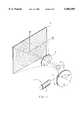
- FIG. 2once more diagrammatically shows the image-generating means 1 and the screen 2 described in more detail in FIG. 1.
- the light beam 5emerges from the image-generating means 1, in particular the optical means 3 illustrated in FIG. 1, and is deflected across the entire angular spatial region 14.
- the light beam 5comprises three individual beams, having the chrominance components red, green and blue, which are united to form a co-linear beam and are modulated, as described with reference to FIG. 1, with a video information.
- FIG. 2diagrammatically illustrates a spectator 16 who is able to view the laser image projected on to the screen 2. According to FIG. 2, said spectator is outside the laser-accessible region 14.
- sensors 22, 24 and 26, as shown in FIG. 5,are arranged in the image-generating means 1 which shows the image-generating means 1 together with the optical means 3 as seen from the screen 2.
- Said sensors 22, 24 and 26monitor a region 17 for the presence of objects or persons.
- the monitored region 17has the size of that region 14 accessible to the laser and includes a monitored edge region 18.
- Said edge region 18, on the sides of the rectangular image, in each caseis at least 10% of the extent of the image, i.e. the monitored region 17 is, in each case, at least 10% larger than the angular spatial region produced by the deflecting means and the optical means 3.
- the dimensions of the edge region 18are selected such that persons, such as the spectator 16, entering into the region 14 at a high speed will be recognized in good time by one of the sensors 22, 24 or 26, as a result of which the image-generating means 1 is switched into a second operating mode which is harmless to a spectator 16 disposed within the region 14 accessible to the laser.
- said second operating modemay involve a switching-off of the laser 4.
- a more rapid protectionis, however, achieved when the laser is blanked, because switching times of less than microseconds are required for the display of images under normal video standards.
- FIG. 3shows, by way of example, the manner in which the image-generating means 1 should be controlled for effective protection.
- three sensors 22, 24, 26are connected to the image-generating means 1 via a monitoring circuit 30.
- output signals of the sensors 24 and 26 with set value transducers 32 and 34are compared via comparators 36 and 38.
- the sensors 24 and 26are infrared-sensitive detectors from which the set value is produced via the set value transducers 32, 34 which are designed to be sensors.
- the sensors allocated to the set value transducers 32 and 34are located outside the monitored region 17 (see FIG. 2) and are also not accessible to any spectators, such that, in principle, they determine the background infrared radiation in the enclosed space and preset a corresponding signal as the threshold value.
- the sensor 22is used for actively monitoring the spatial region, as will be set out in more detail hereinafter.
- the signals of the sensor 22, 24 and 26are OR-gated at the node 40, such that it is possible to influence the image-generating means 1 by each of the sensors.
- the image-generating means 1is provided with three lasers 42, 44, 46, the laser beams of which are combined to form a joint light beam 5 and are directed on to the screen 2 via a deflecting means 47 which comprises a polygonal mirror 8 and a swivel mirror 9.
- the light intensities of the lasers 42, 44, 46are controlled by a controlling device 48, which is fed a video signal 50, by means of which the synchronization of the deflecting means 47 is also carried out via the line 52.
- the controlling device 48also comprises the current supply for the lasers 42, 44, 46, such that, in the simplest case, the current supply to the lasers 42, 44, 46 is disconnected with the aid of the signal from the node 40, to safeguard against any dangers on the grounds of the light beam 5.
- a pilot laser 54is provided for emitting a pilot laser beam 56.
- This pilot laser 54is also rastered and scans the monitored region 17.
- the above-mentioned sensor 22is tuned to the wavelength of the pilot laser 54 in that a ⁇ -filter is connected upstream, such that it is sensitive essentially only to the wavelength of the pilot laser beam 56. For this reason, it is generally possible, in the case of the sensor 22, to dispense with a set-value comparison for suppressing interference signals, as for the sensors 24 and 26.
- Rastering of the pilot laser 56is synchronized by means of a control circuit 58.
- the lasers 42, 44, 46are then blanked only in those spatial regions in which the light beam 5, used for the projection, would impinge on the object. This blanking is carried out via the intensity control for the lasers 42, 44, 46, which intensity control is disposed within the controlling device and is capable of switching within 1/10 ⁇ s.
- An object or a spectator 16will thus be perceived on the screen 2 merely in the form of a shadow image and has an only negligible effect on the pictorial experience of the remaining spectators and only in a small region of the display.
- this safety deviceit is advantageously possible for a projection to take place even when reflecting objects are erected in the region between the image-generating means 1 and the screen 2, as may be the case during shows. This is possible because these objects are also detected by the pilot laser beam 56, i.e. the control circuit prevents the light beam 5 used for the projection from impinging on such objects. Without adversely affecting the safety aspect, it is thus also possible for objects to be arranged between the image-generating means 1 and the screen 2, which gives the performer staging the show a greater degree of artistic freedom.
- the pilot laser 54was replaced by an LED which was modulated and, in particular, pulse modulated.
- a delay measurementwas provided in the controlling device 48, i.e. the pulses were evaluated with regard to the time which the light beam 56 required from the moment of leaving the light-emitting diode until it reached the sensor 22. This also provides a depth information regarding the objects. Instead of a complete switching-off, it is then possible for the lasers 42, 44, 46 to be blanked to a lower intensity, depending on the distance of the interfering object or a spectator 16 from the image-generating means 1.
- acoustic wavesin particular in the ultrasonic range.
- the senor 22must be designed to be an acoustically sensitive element.
- a single sensor 22would suffice for ensuring safety when using the pilot laser 54, the corresponding light-emitting diode or a generator for acoustic waves.
- an additional degree of safetyis provided by the circuitry comprising the sensors 24, 26 and the set value transducers 32, 34, which will switch off the lasers 42, 44, 46 in all instances when the signal detected by the sensors 24 and 26 and the results of the monitoring by the sensor 22 are not consistent.
- the controlling device 48via a corresponding switching, then assumes there to be a malfunction of the sensors or of the logic circuit linking said sensors. As a result hereof, an additional safeguard is provided, since the correct function of the sensors is also monitored.
- the logic switching for blanking the light beam 5is also relatively simple, since it is not necessary to provide any additional synchronizing switchings.
- both light beams 5 and 56are always in the same position, such that the blanking is reduced by a simple dimmer switch for the intensity signal of the lasers 42, 44, 46, as a factor depending on the signal received by the detector.
- pilot laser beam 56In respect of the pilot laser beam 56, a particularly high parallelism is not required. Indeed, it is desirable that the pilot laser beam 56 be expanded beyond the projection laser beam 5, since the edge region 18 which is described above as being advantageous, is then also provided in the present exemplified embodiment.
- the approximate conditions for securing an edge region in this exemplified embodimentare illustrated in FIG. 4. This clearly shows that the light beam 5 used for the projection is concentric with the pilot laser beam 56.
- the pilot laser beam 56is also expanded substantially, such that the desired edge region 18 is provided in a simple manner. The required expansion of the pilot laser beam is always provided, for example, when the above-described light-emitting diode is used instead of the laser 54.
- the pilot laser beam 56is superimposed coaxially and divergently on the projection laser beam 5.
- the coaxial arrangementwhich simplifies, in particular, any adjusting operations.
- the crucial factor in this regardis that the light beam 5 impinges on the screen 2 in the vicinity of the centre of the pilot laser beam 56.
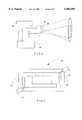
- FIG. 5shows the front view of the image-generating means 1 by way of example.
- the optical means 3, from which the projection light beam 5 emerges,is clearly shown.
- the sensors 22, 24 and 26are clearly arranged in the vicinity of the optical means 3. This is particularly advantageous, since this makes it possible, in a simple manner, to meet the requirement that the region detected by the sensors 22, 24 and 26 should encompass practically the entire region 14 accessible to the laser.
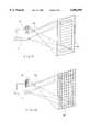
- FIG. 6shows a slightly different exemplified embodiment of the invention which, in addition to the above-described sensors 22, 24 for switching-off purposes, also comprises a motion detector 60.
- this motion detector 60it is possible for motionless objects to be distinguished from moving persons. In show business, this is also advantageous, since the safety switching is required to respond only to persons in the monitored region. It is possible to provide additional safety for non-moving persons by means of a thermopile sensor, which is switched similarly to the sensors 22 or 24.
- the motion detector 60is connected to the controlling device 48 which, in a specific exemplified embodiment, however simply blocks the projection laser beam 5 by means of a shutter.
- the present exemplified embodimentalso shows a key-operated switch 62, which permits a restoring of power to the device only under the supervision of trained personnel.
- a diaphragm 64 for detecting the monitored region of the enclosed spaceis provided.
- FIG. 7A diaphragm of this kind is illustrated in FIG. 7, and this is designed, primarily, in an advantageous manner for an exemplified embodiment in which the optical means 3 is a variable system for changing image sizes.
- the image size which is to be displayedit is advantageous in professional apparatus for the image size which is to be displayed to be variable.
- two variable diaphragm parts 68 and 70are provided in the diaphragm 64 of FIG. 7, and it is possible for said diaphragm parts to be in reciprocating motion due to the stepping motors 72 and 74, such that the monitored region is correlated to the image size to be displayed, depending on the required use.
- the stepping motors 72 and 74are actuated dependent upon the variable optical means.
- the resultant sequence of automatic operations providedalso increases safety, since maladjustments of the monitored region 17 relative to the region 14 accessible to the laser are prevented.
- the stepping-motor controlemits a signal by means of which the projection laser beam 5 is blanked until the correct size of the monitored region is adjusted via the stepping motors 72 and 74.
- the danger-posing risks in respect of personsare also reduced.
- FIG. 6a small region in the vicinity of the laser projector 1 exists when the motion detector 60 is arranged slightly beyond the optical means 3 of the laser projector 1, in which small region monitoring is not possible.
- motion detectors 72, 74, 76, 78are provided in the exemplified embodiment according to FIG. 8, for four spatial planes, by means of which motion detectors it is possible to monitor movement in the edge regions of the region 14 accessible to the laser.
- FIG. 8also again shows a key-operated switch 62, a controlling device 48 and the image-generating means 1, which all have the same functions as described in respect of the example in FIG. 6.
- the peripheral monitoring according to FIG. 8utilizes the characteristic feature of motion detectors, namely that they are sensitive to movement essentially only in one spatial direction.
- the direction of motion sensitivity of the motion detectors 72, 74, 76 and 78is diagrammatically illustrated by arrows.
- FIG. 9shows the full monitoring of the enclosed space by means of thermopile line sensors.
- the spaceis monitored in partial regions subdivided into lines.
- FIG. 9shows the resulting detection characteristic 80.
- an optical means 82is used which images the monitored spatial region on to a line 84 of a pyrometer. This provides a linear position information for monitoring. The position information is used, after appropriate evaluation, to switch off the laser only in partial regions in which an object or a viewer 16 has penetrated into the region 14 accessible to the laser.
- FIG. 10shows a relatively improved exemplified embodiment, comprising a matrix-like detection characteristic 86.
- Said detection characteristicis, in this instance, provided by an optical means 88 which focusses the monitored region on to a sensor matrix 90.
- the sensor matrix 90it is also possible for the sensor matrix 90 to be a pyrometric matrix or a plurality of thermopile sensors in a matrix arrangement.
- CCD elementsare also suitable and these are read, for evaluating the monitoring and for attenuating the light beam 5, in the same manner as in a television CCD camera, whereupon a corresponding switch blanks the light beam 5 only in the spatial regions in which an object or a viewer is detected by the sensor matrix 90.
- FIG. 11shows an exemplified embodiment in which the safety monitoring is carried out by means of a pilot laser beam 97.
- Said pilot laser beamis also rastered, but the raster field is considerably larger than that of the laser used for image generating.
- an edge regionis also produced and this is provided to ensure a rapid switching-off of the laser via the safety device before an object or a person can penetrate into the projection region 14.
- the laser beam 5 for displaying the image and the projection laser beam 97are rastered by the same deflecting means 47.
- the raster region of the deflecting means 47was, however, enlarged relative to the region required for the image display.
- the laser beam 5 for the projectionis blanked during the entire duration of the sweeping of the edge region 18. As a result, an edge region which is rastered only by the pilot laser beam 97 is produced.
- FIG. 12shows a flow chart of an active laser safety device which is provided, in particular, for domestic use.
- the step 100 shown in FIG. 12denotes switching-on of the laser projector with blanked laser light.
- step 102which, from a control point of view is repeated continuously, the modulators of the laser beam are also blanked, and a pilot laser beam is directed into the projection space.
- the projection laser beam 97is pulse modulated and a delay measurement is provided.
- the delay measurementwhen the laser beam for displaying the image is switched off, the time delay over the phase position of the detected and reflected pilot laser beam 97 is recorded and evaluated. If it is established, during the evaluation of the time delay, that an object is present in the projection region, the control switches back to the step 102 via the path 108, until no object is detected within the safety region.
- step 112the control switches to step 112, via the path 110, in which step the modulators for the lasers are switched to modulation for image-displaying.
- step 112the modulators for the lasers are switched to modulation for image-displaying.
- the phasecontinues to be monitored in step 112.
- the local phase positionsare also stored in step 104, such that it is possible for the respective phase detected in step 112 to be compared with the stored phase.
- step 104it is possible to provide a high degree of flexibility with regard to the spacing of the screen from the image-generating means 1.
- step 114the phase position is again interrogated as to whether an object has been detected. If an object has been detected, the control, via the step 108, switches back to step 102 in which the modulators are switched off and the laser beam 5 is blanked. If no object is detected, the phase of the pilot laser beam is again measured in step 116 and examined again in step 112 as to the detection of an object in the safety area.
- FIG. 13shows a flow chart of a combined passive laser safety device which is provided, in particular, for professional use.
- the sequence of the safety programmeis carried out by a combination of two sensors, i.e. a pyroelectric sensor and a thermopile sensor.
- step 120again involves switching-on the laser projector, and step 122 the switching-off of the modulators, in order to blank the laser beam 5 for displaying the image.
- a learning phaseis provided in step 124, for measuring the temperature in the projection space and for tuning the pyroelectric motion detectors.
- step 126the control switches back to step 122 if a movement was detected, such that the so-called learning phase recommences in step 124 with the switched-off laser beam 5.
- an interrogationis carried out, via the step 128, for an increased room temperature.
- step 122If the room temperature is elevated during the measuring process, the control also switches back to step 122, such that the learning phase in step 124 recommences with switched-off laser beam 5. If the room temperature has remained constant, the control then measures reference values for the room temperature, for comparing with sensor signals. In this regard, movements are detected via the pyroelectric sensor. In the absence of a motion signal, the control switches to step 130 in which the modulators are switched on for modulation of the laser beam 5. This means, that image-displaying can now commence. If the motion detector detects a movement in the safety area during step 132, the control is returned to step 122.
- step 124the modulators are switched off, and the motion detectors and the room temperature are newly determined in step 124 under supervision of the personnel, for measuring the temperature in the projection space. Otherwise, the room temperature is measured in step 134, and the pyroelectric sensor for detecting movement is adapted to the current room temperature. The control then again switches to step 130, whereupon the motion detector is again interrogated in step 132, etc.
- the above exemplified embodimentsshow the wide range of possibilities for providing a safety device of the aforementioned kind.
- various meanshave been shown for ensuring the greatest possible degree of safety by additional circuitry, in particular, also of additional sensors.
- the monitoring in partial regionsis, in particular, particularly advantageous in the practical sphere for television projections, since persons entering the safety area are visible on the projection screen only in the form of a shadow image. The pictorial effect is thus not substantially affected.
Landscapes
- Physics & Mathematics (AREA)
- Optics & Photonics (AREA)
- Engineering & Computer Science (AREA)
- Multimedia (AREA)
- Signal Processing (AREA)
- General Physics & Mathematics (AREA)
- Control Of Indicators Other Than Cathode Ray Tubes (AREA)
- Video Image Reproduction Devices For Color Tv Systems (AREA)
- Controls And Circuits For Display Device (AREA)
- Projection Apparatus (AREA)
- Transforming Electric Information Into Light Information (AREA)
- Display Devices Of Pinball Game Machines (AREA)
- Liquid Crystal (AREA)
- Mechanical Optical Scanning Systems (AREA)
- Lasers (AREA)
- Overhead Projectors And Projection Screens (AREA)
- Endoscopes (AREA)
- Magnetic Resonance Imaging Apparatus (AREA)
- Apparatus For Radiation Diagnosis (AREA)
- Geophysics And Detection Of Objects (AREA)
- Devices For Indicating Variable Information By Combining Individual Elements (AREA)
- Reverberation, Karaoke And Other Acoustics (AREA)
Abstract
Description
Claims (21)
Applications Claiming Priority (3)
| Application Number | Priority Date | Filing Date | Title |
|---|---|---|---|
| DE19640404ADE19640404A1 (en) | 1996-09-30 | 1996-09-30 | Device for displaying images |
| DE19640404 | 1996-09-30 | ||
| PCT/EP1997/004834WO1998015127A1 (en) | 1996-09-30 | 1997-09-06 | Device for image projection |
Publications (1)
| Publication Number | Publication Date |
|---|---|
| US6002505Atrue US6002505A (en) | 1999-12-14 |
Family
ID=7807512
Family Applications (1)
| Application Number | Title | Priority Date | Filing Date |
|---|---|---|---|
| US09/077,413Expired - Fee RelatedUS6002505A (en) | 1996-09-30 | 1997-09-06 | Device for image projection |
Country Status (14)
| Country | Link |
|---|---|
| US (1) | US6002505A (en) |
| EP (1) | EP0864230B1 (en) |
| JP (1) | JP2994469B2 (en) |
| KR (1) | KR100294425B1 (en) |
| CN (1) | CN1107419C (en) |
| AT (1) | ATE210358T1 (en) |
| AU (1) | AU734560B2 (en) |
| BR (1) | BR9706764A (en) |
| CA (1) | CA2237764C (en) |
| DE (2) | DE19640404A1 (en) |
| IL (1) | IL124357A (en) |
| RU (1) | RU98111821A (en) |
| WO (1) | WO1998015127A1 (en) |
| ZA (1) | ZA977965B (en) |
Cited By (81)
| Publication number | Priority date | Publication date | Assignee | Title |
|---|---|---|---|---|
| US6170953B1 (en)* | 1999-03-22 | 2001-01-09 | Samsung Electronics Co., Ltd. | Laser video projector for projecting image to a plurality of screens |
| US6262781B1 (en)* | 1996-07-19 | 2001-07-17 | Ltd Gmbh & Co. Laser-Display-Technologie Kg | Video projection apparatus and method of displaying a video image composed of pixels of a defined size |
| US6370260B1 (en) | 1999-09-03 | 2002-04-09 | Honeywell International Inc. | Near-IR human detector |
| US20020044674A1 (en)* | 1999-09-03 | 2002-04-18 | Ioannis Pavlidis | Near-infrared disguise detection |
| US6431731B1 (en)* | 1999-03-15 | 2002-08-13 | Mark Howard Krietzman | Laser device and method for producing diffuse illumination |
| US6460999B1 (en)* | 1999-09-03 | 2002-10-08 | Sony Corporation | Projector and the protector thereof |
| US20030053664A1 (en)* | 2001-09-13 | 2003-03-20 | Ioannis Pavlidis | Near-infrared method and system for use in face detection |
| US6575581B2 (en)* | 1999-12-28 | 2003-06-10 | Sony Corporation | Image projection method and image projector |
| WO2003104892A1 (en)* | 2002-06-10 | 2003-12-18 | ソニー株式会社 | Image projector and image projecting method |
| WO2004051344A1 (en)* | 2002-11-29 | 2004-06-17 | Brother Kogyo Kabushiki Kaisha | Image display device |
| EP1365584A3 (en)* | 2002-05-20 | 2004-11-10 | Seiko Epson Corporation | Projector-type image display system, projector, information storage medium and image projection method |
| US20050024595A1 (en)* | 2003-07-09 | 2005-02-03 | Toru Suzuki | Image projecting device and image projecting method |
| US6854879B2 (en) | 2001-04-19 | 2005-02-15 | Honeywell International Inc. | System and method using thermal image analysis for polygraph testing |
| US20050068500A1 (en)* | 2003-09-26 | 2005-03-31 | Nec Viewtechnology, Ltd. | Projection display device |
| WO2005057919A1 (en)* | 2003-12-01 | 2005-06-23 | Eastman Kodak Company | Laser projector having silhouette blanking |
| WO2005067309A1 (en)* | 2003-12-31 | 2005-07-21 | Symbol Technologies, Inc. | Method and apparatus for controllably reducing power delivered by a laser projection display |
| US6996256B2 (en) | 2000-06-08 | 2006-02-07 | Honeywell International Inc. | Detection system and method using thermal image analysis |
| US20060116555A1 (en)* | 2004-11-18 | 2006-06-01 | Honeywell International Inc. | Controlled environment thermal image detection system and methods regarding same |
| US20060170871A1 (en)* | 2005-02-01 | 2006-08-03 | Dietz Paul H | Anti-blinding safety feature for projection systems |
| US7111980B2 (en) | 2001-04-19 | 2006-09-26 | Honeywell International Inc. | System and method using thermal image analysis and slope threshold classification for polygraph testing |
| WO2006101739A3 (en)* | 2005-03-17 | 2007-04-12 | Patrick Murphy | Audience scanning laser display projector and associated methods |
| EP1379916A4 (en)* | 2001-02-16 | 2007-08-29 | Imatte Inc | Method and apparatus for inhibiting projection of selected areas of a projected image |
| EP1368705A4 (en)* | 2001-02-16 | 2007-08-29 | Imatte Inc | Interactive teleconferencing display system |
| US20080158522A1 (en)* | 2006-12-27 | 2008-07-03 | Samsung Electronics Co., Ltd | Laser projector for controlling power to drive laser diodes and method thereof |
| US20080204664A1 (en)* | 2007-02-26 | 2008-08-28 | Z-Laser Optoelektronik Gmbh | Method and Apparatus for Projecting an Optical Projection onto a Projection Surface |
| US20080266409A1 (en)* | 2004-08-12 | 2008-10-30 | Bioscrypt, Inc. | Device for Contactlessly Controlling the Surface Profile of Objects |
| US20090027571A1 (en)* | 2006-02-28 | 2009-01-29 | Brother Kogyo Kabushiki Kaisha | Image display device |
| WO2008155771A3 (en)* | 2007-06-21 | 2009-02-12 | Maradin Technologies Ltd | Image projection system with feedback |
| US20090051827A1 (en)* | 2005-05-31 | 2009-02-26 | Matsushita Electric Industrial Co., Ltd. | Display device |
| US20090147224A1 (en)* | 2005-09-21 | 2009-06-11 | Akira Kurozuka | Image projection device |
| US20090185249A1 (en)* | 2006-02-10 | 2009-07-23 | Hiroshi Obi | Scanning unit and image display device |
| US20090190103A1 (en)* | 2008-01-29 | 2009-07-30 | Funai Electric Co., Ltd. | Laser projector performing laser raster scan using a scanning mirror |
| US20090262262A1 (en)* | 2005-08-26 | 2009-10-22 | Tatsuo Itoh | Projection type display apparatus |
| US20100053591A1 (en)* | 2007-12-05 | 2010-03-04 | Microvision, Inc. | Scanned Proximity Detection Method and Apparatus for a Scanned Image Projection System |
| US20100073580A1 (en)* | 2006-09-14 | 2010-03-25 | Koninklijke Philips Electronics N.V. | Laser projector with alerting light |
| US20100157253A1 (en)* | 2005-06-29 | 2010-06-24 | Koninklijke Philips Electronics, N.V. | Method and system of scanning laser beam image projection |
| US20100177929A1 (en)* | 2009-01-12 | 2010-07-15 | Kurtz Andrew F | Enhanced safety during laser projection |
| US20100245781A1 (en)* | 2009-03-26 | 2010-09-30 | Sanyo Electric Co., Ltd. | Projection display apparatus |
| US7891818B2 (en) | 2006-12-12 | 2011-02-22 | Evans & Sutherland Computer Corporation | System and method for aligning RGB light in a single modulator projector |
| US8045247B2 (en)* | 2007-04-06 | 2011-10-25 | Prysm, Inc. | Post-objective scanning beam systems |
| US20110267501A1 (en)* | 2010-04-28 | 2011-11-03 | Microsoft Corporation | Scanned beam display and image capture |
| US8077378B1 (en) | 2008-11-12 | 2011-12-13 | Evans & Sutherland Computer Corporation | Calibration system and method for light modulation device |
| US20110316438A1 (en)* | 2008-12-04 | 2011-12-29 | Skaret Ab | Fixture for emulation of omnidirectional or directed continuous lighting |
| US20120092630A1 (en)* | 2009-07-31 | 2012-04-19 | Kunitaka Furuichi | Projection type display device and light amount adjustment method |
| US8262236B2 (en) | 2008-06-17 | 2012-09-11 | The Invention Science Fund I, Llc | Systems and methods for transmitting information associated with change of a projection surface |
| US8267526B2 (en) | 2008-06-17 | 2012-09-18 | The Invention Science Fund I, Llc | Methods associated with receiving and transmitting information related to projection |
| US8308304B2 (en) | 2008-06-17 | 2012-11-13 | The Invention Science Fund I, Llc | Systems associated with receiving and transmitting information related to projection |
| US20120293776A1 (en)* | 2011-05-20 | 2012-11-22 | Samsung Electronics Co., Ltd. | Projector and control method thereof |
| US8358317B2 (en) | 2008-05-23 | 2013-01-22 | Evans & Sutherland Computer Corporation | System and method for displaying a planar image on a curved surface |
| US8376558B2 (en) | 2008-06-17 | 2013-02-19 | The Invention Science Fund I, Llc | Systems and methods for projecting in response to position change of a projection surface |
| US8384005B2 (en) | 2008-06-17 | 2013-02-26 | The Invention Science Fund I, Llc | Systems and methods for selectively projecting information in response to at least one specified motion associated with pressure applied to at least one projection surface |
| US8602564B2 (en) | 2008-06-17 | 2013-12-10 | The Invention Science Fund I, Llc | Methods and systems for projecting in response to position |
| US8608321B2 (en) | 2008-06-17 | 2013-12-17 | The Invention Science Fund I, Llc | Systems and methods for projecting in response to conformation |
| US8641203B2 (en) | 2008-06-17 | 2014-02-04 | The Invention Science Fund I, Llc | Methods and systems for receiving and transmitting signals between server and projector apparatuses |
| EP2696586A1 (en) | 2012-08-06 | 2014-02-12 | ST-Ericsson SA | Safety feature for projection subsystem using laser technology |
| WO2014041464A1 (en) | 2012-09-11 | 2014-03-20 | Barco N.V. | Projection system with safety detection |
| US8702248B1 (en) | 2008-06-11 | 2014-04-22 | Evans & Sutherland Computer Corporation | Projection method for reducing interpixel gaps on a viewing surface |
| US8723787B2 (en) | 2008-06-17 | 2014-05-13 | The Invention Science Fund I, Llc | Methods and systems related to an image capture projection surface |
| US8733952B2 (en) | 2008-06-17 | 2014-05-27 | The Invention Science Fund I, Llc | Methods and systems for coordinated use of two or more user responsive projectors |
| US8820939B2 (en) | 2008-06-17 | 2014-09-02 | The Invention Science Fund I, Llc | Projection associated methods and systems |
| US8857999B2 (en) | 2008-06-17 | 2014-10-14 | The Invention Science Fund I, Llc | Projection in response to conformation |
| CN104224322A (en)* | 2013-06-06 | 2014-12-24 | 西门子公司 | Projection device and method for operating a projection device |
| US8936367B2 (en) | 2008-06-17 | 2015-01-20 | The Invention Science Fund I, Llc | Systems and methods associated with projecting in response to conformation |
| US8944608B2 (en) | 2008-06-17 | 2015-02-03 | The Invention Science Fund I, Llc | Systems and methods associated with projecting in response to conformation |
| US9004698B2 (en) | 2009-07-31 | 2015-04-14 | Lemoptix Sa | Optical micro-projection system and projection method |
| US20150186039A1 (en)* | 2012-08-27 | 2015-07-02 | Citizen Holdings Co., Ltd. | Information input device |
| US20160234468A1 (en)* | 2015-02-09 | 2016-08-11 | Lenovo (Beijing) Co., Ltd. | Projection Method and Electronic Device |
| US9641826B1 (en) | 2011-10-06 | 2017-05-02 | Evans & Sutherland Computer Corporation | System and method for displaying distant 3-D stereo on a dome surface |
| US9816027B2 (en) | 2011-04-15 | 2017-11-14 | Sekisui Chemical Co., Ltd. | Method for producing a film having luminescent particles |
| US20170373454A1 (en)* | 2016-06-28 | 2017-12-28 | Alexander Hay | Laser Safety Device |
| US9855727B2 (en) | 2010-09-21 | 2018-01-02 | Sekisui Chemical Co., Ltd. | Glass pane as head-up display |
| US9922621B2 (en) | 2011-08-29 | 2018-03-20 | Sekisui Chemical Co., Ltd. | Device for generating a display image on a composite glass pane |
| US20190222815A1 (en)* | 2016-09-21 | 2019-07-18 | Nec Corporation | Projection system, projection method, and program recording medium |
| US10528003B2 (en) | 2015-01-28 | 2020-01-07 | Seereal Technologies S.A. | Light modulation device having an optical element for scattering light |
| WO2019222270A3 (en)* | 2018-05-16 | 2020-02-27 | Dolby Laboratories Licensing Corporation | Projector controller and associated method |
| EP3627222A1 (en)* | 2018-09-19 | 2020-03-25 | Canon Kabushiki Kaisha | Control apparatus, control method, program and computer-readable medium |
| CN112213853A (en)* | 2019-07-10 | 2021-01-12 | 度逢株式会社 | Optical scanning device, object detection device, optical scanning method, object detection method, and program |
| EP3813493A1 (en) | 2019-10-23 | 2021-04-28 | OSRAM GmbH | Lighting apparatus, and corresponding system, method and computer program product |
| US11086405B2 (en) | 2011-12-28 | 2021-08-10 | Nikon Corporation | Display device and projection device |
| US11178745B2 (en) | 2019-10-23 | 2021-11-16 | Osram Gmbh | Lighting apparatus and corresponding system, method and computer program product |
| WO2022034460A1 (en)* | 2020-08-12 | 2022-02-17 | Imax Theatres International Limited | Methods and systems for controlling light output based on a light level threshold at a boundary |
Families Citing this family (41)
| Publication number | Priority date | Publication date | Assignee | Title |
|---|---|---|---|---|
| JP2002006397A (en)* | 2000-06-22 | 2002-01-09 | Sony Corp | Image display device |
| JP4620901B2 (en)* | 2001-06-04 | 2011-01-26 | キヤノン株式会社 | Two-dimensional optical scanning device and method for driving the two-dimensional optical scanning device |
| US7106516B2 (en) | 2002-02-04 | 2006-09-12 | Applied Films Gmbh & Co. Kg | Material with spectrally selective reflection |
| JP4068365B2 (en)* | 2002-02-26 | 2008-03-26 | 株式会社リコー | Coordinate input device |
| JP4366631B2 (en)* | 2002-06-10 | 2009-11-18 | ソニー株式会社 | Image projection apparatus and image projection method |
| JP4385735B2 (en)* | 2002-11-29 | 2009-12-16 | ブラザー工業株式会社 | Image display device |
| JP3849654B2 (en) | 2003-02-21 | 2006-11-22 | 株式会社日立製作所 | Projection display |
| JP4517601B2 (en)* | 2003-07-09 | 2010-08-04 | ソニー株式会社 | Projection type image display device |
| JP4433762B2 (en)* | 2003-10-29 | 2010-03-17 | ソニー株式会社 | Projection apparatus and video projection method |
| WO2005046249A1 (en)* | 2003-11-06 | 2005-05-19 | Martin Professional A/S | Safety laser device |
| JP4505718B2 (en)* | 2003-12-10 | 2010-07-21 | ソニー株式会社 | Image display device |
| JP2006091121A (en)* | 2004-09-21 | 2006-04-06 | Sanyo Electric Co Ltd | Projection video display |
| DE102004048995A1 (en)* | 2004-10-04 | 2006-04-13 | Siemens Ag | Earth atmosphere penetrating cosmic object detection procedure compares infrared sensor temperature images with and without cosmic object |
| JP4504802B2 (en)* | 2004-12-24 | 2010-07-14 | 富士フイルム株式会社 | Projection type image display device |
| CN101203801A (en)* | 2005-06-24 | 2008-06-18 | 松下电器产业株式会社 | Image projection device and rear projection display device |
| JP2007206488A (en)* | 2006-02-03 | 2007-08-16 | Seiko Npc Corp | Projection type display device |
| US7919742B2 (en) | 2007-05-21 | 2011-04-05 | Seiko Epson Corporation | Projector having a light intensity control unit for controlling light intensity of projected light and control method of projector |
| WO2009001274A1 (en)* | 2007-06-26 | 2008-12-31 | Philips Intellectual Property & Standards Gmbh | Laser scanning projection device with splitting element |
| KR100780922B1 (en)* | 2007-07-27 | 2007-12-03 | (주)유한프리젠 | Projection system |
| JP5084422B2 (en)* | 2007-09-25 | 2012-11-28 | 日本信号株式会社 | Projection display device |
| CN101424864B (en)* | 2007-11-01 | 2011-06-08 | 鸿富锦精密工业(深圳)有限公司 | Projection device protective system and protection method |
| JP5157381B2 (en)* | 2007-11-14 | 2013-03-06 | 船井電機株式会社 | Image display device |
| JP5338067B2 (en)* | 2007-11-16 | 2013-11-13 | セイコーエプソン株式会社 | projector |
| JP2009163119A (en)* | 2008-01-09 | 2009-07-23 | Seiko Epson Corp | Image projection system and screen device |
| DE102009045810A1 (en)* | 2009-10-19 | 2011-04-21 | Robert Bosch Gmbh | Projector for projecting light on projection surface to produce image of e.g. object on surface, has proximity sensor e.g. capacitive proximity sensor, detecting whether person or object enters into fixed spatial region |
| CN102375309A (en)* | 2010-08-26 | 2012-03-14 | 鸿富锦精密工业(深圳)有限公司 | System and method for adjusting light rays of projector |
| JP4883332B2 (en)* | 2010-09-21 | 2012-02-22 | 三洋電機株式会社 | Projection display device |
| DE102011075147A1 (en)* | 2011-05-03 | 2012-11-08 | Osram Ag | PROJECTION DEVICE FOR PROJECTING AT LEAST ONE PICTURE POINT AND PROCESS FOR OPERATING A PROJECTION DEVICE |
| DE102011075133A1 (en)* | 2011-05-03 | 2012-11-08 | Osram Ag | PROJECTION DEVICE FOR PROJECTING AT LEAST ONE PICTURE POINT AND PROCESS FOR OPERATING A PROJECTION DEVICE |
| DE102011079308A1 (en)* | 2011-05-23 | 2012-11-29 | TV Text International Fernsehtext-Produktion GmbH | Text projection device |
| DE102011106487A1 (en)* | 2011-06-14 | 2012-12-20 | Navigon Ag | Method for operating e.g. mobile electronic device, involves controlling projection of laser projection device by projection control device based on identification of body parts at projection region by body part detection device |
| CN102832530B (en)* | 2011-06-17 | 2014-05-28 | 亚洲光学股份有限公司 | Laser system with safety protection function |
| DE102011081008A1 (en)* | 2011-08-16 | 2013-02-21 | Robert Bosch Gmbh | Laser projection device and method |
| KR101389304B1 (en)* | 2012-01-17 | 2014-04-30 | 최유진 | A system for image indicate of vehicle danger situation and its operational method thereof |
| JP5875953B2 (en)* | 2012-07-17 | 2016-03-02 | 株式会社東芝 | Optical device |
| KR101496275B1 (en)* | 2013-10-11 | 2015-02-26 | 조민석 | Device for studying nuclear medicine imaging camera and studying method thereby |
| CN104698727B (en)* | 2015-03-24 | 2017-01-11 | 海信集团有限公司 | Human body protection method and device for laser projection device and laser projection device |
| DE102016215746A1 (en) | 2016-08-23 | 2018-03-01 | Robert Bosch Gmbh | Projector with non-contact control |
| JP6790223B2 (en)* | 2017-02-24 | 2020-11-25 | ソニーモバイルコミュニケーションズ株式会社 | Information processing equipment, information processing methods, and programs |
| DE102017204668A1 (en)* | 2017-03-21 | 2018-09-27 | Robert Bosch Gmbh | An object detection apparatus and method for monitoring a light projection surface for intrusion of an object |
| CN114019756A (en)* | 2020-07-28 | 2022-02-08 | 青岛海信激光显示股份有限公司 | Laser projection equipment and human eye protection method |
Citations (1)
| Publication number | Priority date | Publication date | Assignee | Title |
|---|---|---|---|---|
| WO1995003676A1 (en)* | 1993-07-23 | 1995-02-02 | Schneider Elektronik Rundfunkwerk Gmbh | Colour video image projection system and associated transformation optics |
Family Cites Families (3)
| Publication number | Priority date | Publication date | Assignee | Title |
|---|---|---|---|---|
| DE3235250C3 (en)* | 1982-09-23 | 1996-04-25 | Maul & Partner Gmbh Wirtschaft | Faceted optics for detecting radiation from a large solid angle, especially for motion detectors |
| US5081542A (en)* | 1989-12-12 | 1992-01-14 | Hughes Aircraft Company | Liquid crystal light valve goggles for eye protection |
| US5255117A (en)* | 1992-02-14 | 1993-10-19 | The United States Of America As Represented By The Secretary Of The Navy | Advanced eye or sensor protection and high speed variable optical attenuation system |
- 1996
- 1996-09-30DEDE19640404Apatent/DE19640404A1/ennot_activeCeased
- 1997
- 1997-09-04ZAZA9707965Apatent/ZA977965B/enunknown
- 1997-09-06ILIL12435797Apatent/IL124357A/ennot_activeIP Right Cessation
- 1997-09-06JPJP10516163Apatent/JP2994469B2/ennot_activeExpired - Fee Related
- 1997-09-06RURU98111821/09Apatent/RU98111821A/ennot_activeApplication Discontinuation
- 1997-09-06KRKR1019980703752Apatent/KR100294425B1/ennot_activeExpired - Fee Related
- 1997-09-06BRBR9706764Apatent/BR9706764A/enunknown
- 1997-09-06AUAU43824/97Apatent/AU734560B2/ennot_activeCeased
- 1997-09-06CNCN97191763Apatent/CN1107419C/ennot_activeExpired - Fee Related
- 1997-09-06EPEP97941983Apatent/EP0864230B1/ennot_activeExpired - Lifetime
- 1997-09-06DEDE59705662Tpatent/DE59705662D1/ennot_activeExpired - Lifetime
- 1997-09-06CACA002237764Apatent/CA2237764C/ennot_activeExpired - Fee Related
- 1997-09-06ATAT97941983Tpatent/ATE210358T1/ennot_activeIP Right Cessation
- 1997-09-06USUS09/077,413patent/US6002505A/ennot_activeExpired - Fee Related
- 1997-09-06WOPCT/EP1997/004834patent/WO1998015127A1/enactiveIP Right Grant
Patent Citations (1)
| Publication number | Priority date | Publication date | Assignee | Title |
|---|---|---|---|---|
| WO1995003676A1 (en)* | 1993-07-23 | 1995-02-02 | Schneider Elektronik Rundfunkwerk Gmbh | Colour video image projection system and associated transformation optics |
Cited By (131)
| Publication number | Priority date | Publication date | Assignee | Title |
|---|---|---|---|---|
| US6262781B1 (en)* | 1996-07-19 | 2001-07-17 | Ltd Gmbh & Co. Laser-Display-Technologie Kg | Video projection apparatus and method of displaying a video image composed of pixels of a defined size |
| US6431731B1 (en)* | 1999-03-15 | 2002-08-13 | Mark Howard Krietzman | Laser device and method for producing diffuse illumination |
| US6170953B1 (en)* | 1999-03-22 | 2001-01-09 | Samsung Electronics Co., Ltd. | Laser video projector for projecting image to a plurality of screens |
| US20020044674A1 (en)* | 1999-09-03 | 2002-04-18 | Ioannis Pavlidis | Near-infrared disguise detection |
| US6460999B1 (en)* | 1999-09-03 | 2002-10-08 | Sony Corporation | Projector and the protector thereof |
| US6370260B1 (en) | 1999-09-03 | 2002-04-09 | Honeywell International Inc. | Near-IR human detector |
| US6718049B2 (en) | 1999-09-03 | 2004-04-06 | Honeywell International Inc. | Near-infrared disguise detection |
| US7076088B2 (en) | 1999-09-03 | 2006-07-11 | Honeywell International Inc. | Near-infrared disguise detection |
| US6829370B1 (en)* | 1999-09-03 | 2004-12-07 | Honeywell International Inc. | Near-IR human detector |
| US6575581B2 (en)* | 1999-12-28 | 2003-06-10 | Sony Corporation | Image projection method and image projector |
| US6996256B2 (en) | 2000-06-08 | 2006-02-07 | Honeywell International Inc. | Detection system and method using thermal image analysis |
| EP1368705A4 (en)* | 2001-02-16 | 2007-08-29 | Imatte Inc | Interactive teleconferencing display system |
| EP1379916A4 (en)* | 2001-02-16 | 2007-08-29 | Imatte Inc | Method and apparatus for inhibiting projection of selected areas of a projected image |
| US7111980B2 (en) | 2001-04-19 | 2006-09-26 | Honeywell International Inc. | System and method using thermal image analysis and slope threshold classification for polygraph testing |
| US6854879B2 (en) | 2001-04-19 | 2005-02-15 | Honeywell International Inc. | System and method using thermal image analysis for polygraph testing |
| US20030053664A1 (en)* | 2001-09-13 | 2003-03-20 | Ioannis Pavlidis | Near-infrared method and system for use in face detection |
| US7027619B2 (en) | 2001-09-13 | 2006-04-11 | Honeywell International Inc. | Near-infrared method and system for use in face detection |
| EP1365584A3 (en)* | 2002-05-20 | 2004-11-10 | Seiko Epson Corporation | Projector-type image display system, projector, information storage medium and image projection method |
| EP1855471A3 (en)* | 2002-05-20 | 2008-05-21 | Seiko Epson Corporation | Projector, information storage medium, and image projection method |
| US20070115396A1 (en)* | 2002-05-20 | 2007-05-24 | Seiko Epson Corporation | Projection-type image display system, projector, program, information storage medium, and image projection method |
| US8284216B2 (en) | 2002-05-20 | 2012-10-09 | Seiko Epson Corporation | Projection-type image display system, projector, and image projection method for avoiding obstacles in the projection area |
| US7626600B2 (en) | 2002-05-20 | 2009-12-01 | Seiko Epson Corporation | Projection-type image display system, projector, information storage medium, and image projection method |
| WO2003104892A1 (en)* | 2002-06-10 | 2003-12-18 | ソニー株式会社 | Image projector and image projecting method |
| EP1513008A4 (en)* | 2002-06-10 | 2006-04-19 | Sony Corp | Image projector and image projecting method |
| US20050128578A1 (en)* | 2002-06-10 | 2005-06-16 | Yutaka Sugawara | Image projector and image projecting method |
| US7364309B2 (en)* | 2002-06-10 | 2008-04-29 | Sony Corporation | Image projector and image projecting method |
| WO2004051344A1 (en)* | 2002-11-29 | 2004-06-17 | Brother Kogyo Kabushiki Kaisha | Image display device |
| US7018055B2 (en)* | 2003-07-09 | 2006-03-28 | Sony Corporation | Image projecting device and image projecting method |
| US20050024595A1 (en)* | 2003-07-09 | 2005-02-03 | Toru Suzuki | Image projecting device and image projecting method |
| EP1519574A3 (en)* | 2003-09-26 | 2005-11-16 | NEC Viewtechnology, Ltd. | Projection display device |
| CN100447661C (en)* | 2003-09-26 | 2008-12-31 | Nec显示器解决方案株式会社 | Projection display device |
| US20050068500A1 (en)* | 2003-09-26 | 2005-03-31 | Nec Viewtechnology, Ltd. | Projection display device |
| US7210786B2 (en) | 2003-09-26 | 2007-05-01 | Nec Viewtechnology, Ltd. | Projection display device |
| US6984039B2 (en) | 2003-12-01 | 2006-01-10 | Eastman Kodak Company | Laser projector having silhouette blanking for objects in the output light path |
| WO2005057919A1 (en)* | 2003-12-01 | 2005-06-23 | Eastman Kodak Company | Laser projector having silhouette blanking |
| WO2005067309A1 (en)* | 2003-12-31 | 2005-07-21 | Symbol Technologies, Inc. | Method and apparatus for controllably reducing power delivered by a laser projection display |
| US20050175048A1 (en)* | 2003-12-31 | 2005-08-11 | Symbol Technologies, Inc. | Method and apparatus for controllably reducing power delivered by a laser projection display |
| US7030353B2 (en) | 2003-12-31 | 2006-04-18 | Symbol Technologies,Inc. | Method and apparatus for controllably reducing power delivered by a laser projection display |
| US20080266409A1 (en)* | 2004-08-12 | 2008-10-30 | Bioscrypt, Inc. | Device for Contactlessly Controlling the Surface Profile of Objects |
| US8238661B2 (en)* | 2004-08-12 | 2012-08-07 | Bioscrypt, Inc. | Device for contactlessly controlling the surface profile of objects |
| US20090179996A2 (en)* | 2004-08-12 | 2009-07-16 | Andrey Klimov | Device for contactlessly controlling the surface profile of objects |
| US20060116555A1 (en)* | 2004-11-18 | 2006-06-01 | Honeywell International Inc. | Controlled environment thermal image detection system and methods regarding same |
| US7138905B2 (en) | 2004-11-18 | 2006-11-21 | Honeywell International Inc. | Controlled environment thermal image detection system and methods regarding same |
| US20060170871A1 (en)* | 2005-02-01 | 2006-08-03 | Dietz Paul H | Anti-blinding safety feature for projection systems |
| US20080192981A1 (en)* | 2005-03-17 | 2008-08-14 | Patrick Murphy | Audience Scanning Laser Display Projector and Associated Methods |
| US7980707B2 (en)* | 2005-03-17 | 2011-07-19 | Patrick Murphy | Audience scanning laser display projector and associated methods |
| WO2006101739A3 (en)* | 2005-03-17 | 2007-04-12 | Patrick Murphy | Audience scanning laser display projector and associated methods |
| US8152314B2 (en) | 2005-05-31 | 2012-04-10 | Panasonic Corporation | Display device |
| US20090051827A1 (en)* | 2005-05-31 | 2009-02-26 | Matsushita Electric Industrial Co., Ltd. | Display device |
| US20100157253A1 (en)* | 2005-06-29 | 2010-06-24 | Koninklijke Philips Electronics, N.V. | Method and system of scanning laser beam image projection |
| US20090262262A1 (en)* | 2005-08-26 | 2009-10-22 | Tatsuo Itoh | Projection type display apparatus |
| US7967452B2 (en) | 2005-08-26 | 2011-06-28 | Panasonic Corporation | Projection type display apparatus |
| US20090147224A1 (en)* | 2005-09-21 | 2009-06-11 | Akira Kurozuka | Image projection device |
| US8182093B2 (en) | 2005-09-21 | 2012-05-22 | Panasonic Corporation | Image projection device including determining displayable region |
| US20090185249A1 (en)* | 2006-02-10 | 2009-07-23 | Hiroshi Obi | Scanning unit and image display device |
| US8149491B2 (en)* | 2006-02-10 | 2012-04-03 | Panasonic Corporation | Scanning unit and image display device |
| US20090027571A1 (en)* | 2006-02-28 | 2009-01-29 | Brother Kogyo Kabushiki Kaisha | Image display device |
| US8246172B2 (en) | 2006-02-28 | 2012-08-21 | Brother Kogyo Kabushiki Kaisha | Image display device |
| US20100073580A1 (en)* | 2006-09-14 | 2010-03-25 | Koninklijke Philips Electronics N.V. | Laser projector with alerting light |
| US8297755B2 (en)* | 2006-09-14 | 2012-10-30 | Koninklijke Philips Electronics N.V. | Laser projector with alerting light |
| US7891818B2 (en) | 2006-12-12 | 2011-02-22 | Evans & Sutherland Computer Corporation | System and method for aligning RGB light in a single modulator projector |
| US20080158522A1 (en)* | 2006-12-27 | 2008-07-03 | Samsung Electronics Co., Ltd | Laser projector for controlling power to drive laser diodes and method thereof |
| US20080204664A1 (en)* | 2007-02-26 | 2008-08-28 | Z-Laser Optoelektronik Gmbh | Method and Apparatus for Projecting an Optical Projection onto a Projection Surface |
| US7976174B2 (en) | 2007-02-26 | 2011-07-12 | Z-Laser Optoelektronik Gmbh | Method and apparatus for projecting an optical projection onto a projection surface |
| US8045247B2 (en)* | 2007-04-06 | 2011-10-25 | Prysm, Inc. | Post-objective scanning beam systems |
| WO2008155771A3 (en)* | 2007-06-21 | 2009-02-12 | Maradin Technologies Ltd | Image projection system with feedback |
| US8251517B2 (en)* | 2007-12-05 | 2012-08-28 | Microvision, Inc. | Scanned proximity detection method and apparatus for a scanned image projection system |
| US20100053591A1 (en)* | 2007-12-05 | 2010-03-04 | Microvision, Inc. | Scanned Proximity Detection Method and Apparatus for a Scanned Image Projection System |
| US8096666B2 (en)* | 2008-01-29 | 2012-01-17 | Funai Electric Co., Ltd. | Laser projector performing laser raster scan using a scanning mirror |
| US20090190103A1 (en)* | 2008-01-29 | 2009-07-30 | Funai Electric Co., Ltd. | Laser projector performing laser raster scan using a scanning mirror |
| US8358317B2 (en) | 2008-05-23 | 2013-01-22 | Evans & Sutherland Computer Corporation | System and method for displaying a planar image on a curved surface |
| US8702248B1 (en) | 2008-06-11 | 2014-04-22 | Evans & Sutherland Computer Corporation | Projection method for reducing interpixel gaps on a viewing surface |
| US8723787B2 (en) | 2008-06-17 | 2014-05-13 | The Invention Science Fund I, Llc | Methods and systems related to an image capture projection surface |
| US8939586B2 (en) | 2008-06-17 | 2015-01-27 | The Invention Science Fund I, Llc | Systems and methods for projecting in response to position |
| US8262236B2 (en) | 2008-06-17 | 2012-09-11 | The Invention Science Fund I, Llc | Systems and methods for transmitting information associated with change of a projection surface |
| US8267526B2 (en) | 2008-06-17 | 2012-09-18 | The Invention Science Fund I, Llc | Methods associated with receiving and transmitting information related to projection |
| US8955984B2 (en) | 2008-06-17 | 2015-02-17 | The Invention Science Fund I, Llc | Projection associated methods and systems |
| US8944608B2 (en) | 2008-06-17 | 2015-02-03 | The Invention Science Fund I, Llc | Systems and methods associated with projecting in response to conformation |
| US8936367B2 (en) | 2008-06-17 | 2015-01-20 | The Invention Science Fund I, Llc | Systems and methods associated with projecting in response to conformation |
| US8308304B2 (en) | 2008-06-17 | 2012-11-13 | The Invention Science Fund I, Llc | Systems associated with receiving and transmitting information related to projection |
| US8857999B2 (en) | 2008-06-17 | 2014-10-14 | The Invention Science Fund I, Llc | Projection in response to conformation |
| US8820939B2 (en) | 2008-06-17 | 2014-09-02 | The Invention Science Fund I, Llc | Projection associated methods and systems |
| US8376558B2 (en) | 2008-06-17 | 2013-02-19 | The Invention Science Fund I, Llc | Systems and methods for projecting in response to position change of a projection surface |
| US8384005B2 (en) | 2008-06-17 | 2013-02-26 | The Invention Science Fund I, Llc | Systems and methods for selectively projecting information in response to at least one specified motion associated with pressure applied to at least one projection surface |
| US8403501B2 (en) | 2008-06-17 | 2013-03-26 | The Invention Science Fund, I, LLC | Motion responsive devices and systems |
| US8430515B2 (en) | 2008-06-17 | 2013-04-30 | The Invention Science Fund I, Llc | Systems and methods for projecting |
| US8540381B2 (en) | 2008-06-17 | 2013-09-24 | The Invention Science Fund I, Llc | Systems and methods for receiving information associated with projecting |
| US8602564B2 (en) | 2008-06-17 | 2013-12-10 | The Invention Science Fund I, Llc | Methods and systems for projecting in response to position |
| US8608321B2 (en) | 2008-06-17 | 2013-12-17 | The Invention Science Fund I, Llc | Systems and methods for projecting in response to conformation |
| US8733952B2 (en) | 2008-06-17 | 2014-05-27 | The Invention Science Fund I, Llc | Methods and systems for coordinated use of two or more user responsive projectors |
| US8641203B2 (en) | 2008-06-17 | 2014-02-04 | The Invention Science Fund I, Llc | Methods and systems for receiving and transmitting signals between server and projector apparatuses |
| US8077378B1 (en) | 2008-11-12 | 2011-12-13 | Evans & Sutherland Computer Corporation | Calibration system and method for light modulation device |
| US8668359B2 (en)* | 2008-12-04 | 2014-03-11 | Patrik Welén | Fixture for emulation of omnidirectional or directed continuous lighting |
| US20110316438A1 (en)* | 2008-12-04 | 2011-12-29 | Skaret Ab | Fixture for emulation of omnidirectional or directed continuous lighting |
| US20100177929A1 (en)* | 2009-01-12 | 2010-07-15 | Kurtz Andrew F | Enhanced safety during laser projection |
| US8290208B2 (en)* | 2009-01-12 | 2012-10-16 | Eastman Kodak Company | Enhanced safety during laser projection |
| US20100245781A1 (en)* | 2009-03-26 | 2010-09-30 | Sanyo Electric Co., Ltd. | Projection display apparatus |
| US9004698B2 (en) | 2009-07-31 | 2015-04-14 | Lemoptix Sa | Optical micro-projection system and projection method |
| US20120092630A1 (en)* | 2009-07-31 | 2012-04-19 | Kunitaka Furuichi | Projection type display device and light amount adjustment method |
| US8619167B2 (en)* | 2010-04-28 | 2013-12-31 | Microsoft Corporation | Scanned beam display and image capture |
| US20110267501A1 (en)* | 2010-04-28 | 2011-11-03 | Microsoft Corporation | Scanned beam display and image capture |
| US10562275B2 (en) | 2010-09-21 | 2020-02-18 | Sekisui Chemical Co., Ltd. | Glass pane as head-up display |
| US9855727B2 (en) | 2010-09-21 | 2018-01-02 | Sekisui Chemical Co., Ltd. | Glass pane as head-up display |
| US9816027B2 (en) | 2011-04-15 | 2017-11-14 | Sekisui Chemical Co., Ltd. | Method for producing a film having luminescent particles |
| US20120293776A1 (en)* | 2011-05-20 | 2012-11-22 | Samsung Electronics Co., Ltd. | Projector and control method thereof |
| US9922621B2 (en) | 2011-08-29 | 2018-03-20 | Sekisui Chemical Co., Ltd. | Device for generating a display image on a composite glass pane |
| US9641826B1 (en) | 2011-10-06 | 2017-05-02 | Evans & Sutherland Computer Corporation | System and method for displaying distant 3-D stereo on a dome surface |
| US10110876B1 (en) | 2011-10-06 | 2018-10-23 | Evans & Sutherland Computer Corporation | System and method for displaying images in 3-D stereo |
| US11086405B2 (en) | 2011-12-28 | 2021-08-10 | Nikon Corporation | Display device and projection device |
| EP2696586A1 (en) | 2012-08-06 | 2014-02-12 | ST-Ericsson SA | Safety feature for projection subsystem using laser technology |
| WO2014023538A1 (en) | 2012-08-06 | 2014-02-13 | St-Ericsson Sa | Safety feature for projection subsystem using laser technology |
| US20150186039A1 (en)* | 2012-08-27 | 2015-07-02 | Citizen Holdings Co., Ltd. | Information input device |
| WO2014041464A1 (en) | 2012-09-11 | 2014-03-20 | Barco N.V. | Projection system with safety detection |
| CN104224322A (en)* | 2013-06-06 | 2014-12-24 | 西门子公司 | Projection device and method for operating a projection device |
| US10528003B2 (en) | 2015-01-28 | 2020-01-07 | Seereal Technologies S.A. | Light modulation device having an optical element for scattering light |
| US20160234468A1 (en)* | 2015-02-09 | 2016-08-11 | Lenovo (Beijing) Co., Ltd. | Projection Method and Electronic Device |
| US9848175B2 (en)* | 2015-02-09 | 2017-12-19 | Lenovo (Beijing) Co., Ltd. | Projection method and electronic device |
| US20170373454A1 (en)* | 2016-06-28 | 2017-12-28 | Alexander Hay | Laser Safety Device |
| US10887563B2 (en)* | 2016-09-21 | 2021-01-05 | Nec Corporation | Projection system, projection method, and program recording medium |
| US20190222815A1 (en)* | 2016-09-21 | 2019-07-18 | Nec Corporation | Projection system, projection method, and program recording medium |
| US11206380B2 (en) | 2018-05-16 | 2021-12-21 | Dolby Laboratories Licensing Corporation | Projector controller and associated method |
| WO2019222270A3 (en)* | 2018-05-16 | 2020-02-27 | Dolby Laboratories Licensing Corporation | Projector controller and associated method |
| US12052531B2 (en) | 2018-05-16 | 2024-07-30 | Dolby Laboratories Licensing Corporation | Projector controller and associated method |
| EP4203466A1 (en)* | 2018-05-16 | 2023-06-28 | Dolby Laboratories Licensing Corporation | Projector controller and associated method |
| EP3627222A1 (en)* | 2018-09-19 | 2020-03-25 | Canon Kabushiki Kaisha | Control apparatus, control method, program and computer-readable medium |
| US11172180B2 (en) | 2018-09-19 | 2021-11-09 | Canon Kabushiki Kaisha | Control apparatus, control method and non-transitory computer-readable medium |
| CN112213853A (en)* | 2019-07-10 | 2021-01-12 | 度逢株式会社 | Optical scanning device, object detection device, optical scanning method, object detection method, and program |
| US11382201B2 (en) | 2019-10-23 | 2022-07-05 | Osram Gmbh | Lighting apparatus, and corresponding system, method and computer program product |
| US11178745B2 (en) | 2019-10-23 | 2021-11-16 | Osram Gmbh | Lighting apparatus and corresponding system, method and computer program product |
| EP3813493A1 (en) | 2019-10-23 | 2021-04-28 | OSRAM GmbH | Lighting apparatus, and corresponding system, method and computer program product |
| WO2022034460A1 (en)* | 2020-08-12 | 2022-02-17 | Imax Theatres International Limited | Methods and systems for controlling light output based on a light level threshold at a boundary |
Also Published As
| Publication number | Publication date |
|---|---|
| CN1107419C (en) | 2003-04-30 |
| DE59705662D1 (en) | 2002-01-17 |
| CN1209935A (en) | 1999-03-03 |
| ATE210358T1 (en) | 2001-12-15 |
| JPH11501419A (en) | 1999-02-02 |
| EP0864230B1 (en) | 2001-12-05 |
| ZA977965B (en) | 1998-03-23 |
| IL124357A0 (en) | 1998-12-06 |
| WO1998015127A1 (en) | 1998-04-09 |
| KR100294425B1 (en) | 2001-09-17 |
| KR19990071481A (en) | 1999-09-27 |
| IL124357A (en) | 2001-03-19 |
| JP2994469B2 (en) | 1999-12-27 |
| AU734560B2 (en) | 2001-06-14 |
| DE19640404A1 (en) | 1998-04-09 |
| CA2237764C (en) | 2001-12-25 |
| RU98111821A (en) | 2000-05-10 |
| BR9706764A (en) | 1999-07-20 |
| AU4382497A (en) | 1998-04-24 |
| CA2237764A1 (en) | 1998-04-09 |
| EP0864230A1 (en) | 1998-09-16 |
Similar Documents
| Publication | Publication Date | Title |
|---|---|---|
| US6002505A (en) | Device for image projection | |
| US7144117B2 (en) | Projection type image display apparatus | |
| US6827454B2 (en) | Imaging prevention method and system | |
| JP7440429B2 (en) | Projector controller and related methods | |
| US20090002644A1 (en) | Invisible scanning safety system | |
| US20090147272A1 (en) | Proximity detection for control of an imaging device | |
| WO2009031094A1 (en) | Laser scanning projection device with eye detection unit | |
| EP1261201A2 (en) | Imaging | |
| CN110476079A (en) | Object-detection equipment and in terms of object invades monitor light perspective plane method | |
| RU2133485C1 (en) | Process detecting means of optical and opticoelectronic type | |
| HK40046599A (en) | Projector controller and projection control method | |
| HK40046599B (en) | Projector controller and projection control method |
Legal Events
| Date | Code | Title | Description |
|---|---|---|---|
| AS | Assignment | Owner name:LDT GMBH & CO. LASER-DISPLAY TECHNOLOGIE KG, GERMA Free format text:ASSIGNMENT OF ASSIGNORS INTEREST;ASSIGNORS:KRAENERT, JUERGEN;DETER, CHRISTHARD;VOGEL, WOLFGANG;AND OTHERS;REEL/FRAME:009593/0595 Effective date:19980514 | |
| FEPP | Fee payment procedure | Free format text:PAYOR NUMBER ASSIGNED (ORIGINAL EVENT CODE: ASPN); ENTITY STATUS OF PATENT OWNER: LARGE ENTITY Free format text:PAYER NUMBER DE-ASSIGNED (ORIGINAL EVENT CODE: RMPN); ENTITY STATUS OF PATENT OWNER: LARGE ENTITY | |
| FPAY | Fee payment | Year of fee payment:4 | |
| AS | Assignment | Owner name:JENOPTIK LDT GMBH, GERMANY Free format text:ASSIGNMENT OF ASSIGNORS INTEREST;ASSIGNOR:SCHNEIDER LASER TECHNOLOGIES AG;REEL/FRAME:014863/0413 Effective date:20031112 Owner name:SCHNEIDER LASER TECHNOLOGIES AG, GERMANY Free format text:ASSIGNMENT OF ASSIGNORS INTEREST;ASSIGNOR:LDT GMBH & CO. LASER-DISPLAY-TECHNOLOGIE KG;REEL/FRAME:014863/0406 Effective date:20000717 | |
| REMI | Maintenance fee reminder mailed | ||
| LAPS | Lapse for failure to pay maintenance fees | ||
| STCH | Information on status: patent discontinuation | Free format text:PATENT EXPIRED DUE TO NONPAYMENT OF MAINTENANCE FEES UNDER 37 CFR 1.362 | |
| FP | Lapsed due to failure to pay maintenance fee | Effective date:20071214 |