US6002424A - Dental imaging system with white balance compensation - Google Patents
Dental imaging system with white balance compensationDownload PDFInfo
- Publication number
- US6002424A US6002424AUS08/873,805US87380597AUS6002424AUS 6002424 AUS6002424 AUS 6002424AUS 87380597 AUS87380597 AUS 87380597AUS 6002424 AUS6002424 AUS 6002424A
- Authority
- US
- United States
- Prior art keywords
- lamp
- white balance
- imaging apparatus
- image
- image sensor
- Prior art date
- Legal status (The legal status is an assumption and is not a legal conclusion. Google has not performed a legal analysis and makes no representation as to the accuracy of the status listed.)
- Expired - Lifetime
Links
- 238000003384imaging methodMethods0.000titleclaimsabstractdescription37
- 238000000034methodMethods0.000claimsabstractdescription10
- 239000011248coating agentSubstances0.000claimsdescription3
- 238000000576coating methodMethods0.000claimsdescription3
- 230000013011matingEffects0.000claims2
- 238000005286illuminationMethods0.000abstractdescription11
- 240000007320Pinus strobusSpecies0.000description3
- 239000000463materialSubstances0.000description2
- 239000003086colorantSubstances0.000description1
- 238000009833condensationMethods0.000description1
- 230000005494condensationEffects0.000description1
- 238000010586diagramMethods0.000description1
- 230000000694effectsEffects0.000description1
- 239000011521glassSubstances0.000description1
- 238000012986modificationMethods0.000description1
- 230000004048modificationEffects0.000description1
- 239000013307optical fiberSubstances0.000description1
- 238000007781pre-processingMethods0.000description1
- 230000001681protective effectEffects0.000description1
- 230000029058respiratory gaseous exchangeEffects0.000description1
Images


Classifications
- H—ELECTRICITY
- H04—ELECTRIC COMMUNICATION TECHNIQUE
- H04N—PICTORIAL COMMUNICATION, e.g. TELEVISION
- H04N7/00—Television systems
- H04N7/18—Closed-circuit television [CCTV] systems, i.e. systems in which the video signal is not broadcast
- H04N7/183—Closed-circuit television [CCTV] systems, i.e. systems in which the video signal is not broadcast for receiving images from a single remote source
Definitions
- This inventionrelates to the field of video imaging and, more specifically, to a video imaging apparatus for use in dental imaging.
- Video imaging camerashave been used for obtaining images in dentistry for some time.
- One example of an existing systemcan be found in U.S. Pat. No. 5,523,782 (Williams), which describes a video dental camera that includes a light source, a CCD, and an adjustable focus lens system.
- Other examples of existing systemcan be found in U.S. Pat. No. 4,575,805 (Moermann et al.), and in U.S. Pat. No. 5,527,261 (Monroe et al.).
- the present inventionadvantageously avoids the aforementioned drawback by compensating for the different white balances that may be encountered by a dental video camera.
- a dental imaging apparatusincludes a housing and an image sensor with an active surface.
- the image sensoris mounted in the housing so that the active surface receives light reflected from a dental subject.
- the apparatusalso includes a lamp for illuminating the dental subject and an image processor for receiving image signals from an image sensor output and processing the image signals in accordance with either a first stored white balance related to a characteristic of the lamp illumination or a second stored white balance.
- a method of obtaining an image of a dental subject using an apparatus including a lamp and an image sensorincludes the steps of receiving image signals from the image sensor and selecting a first or a second mode of operation.
- the image signalsare processed in accordance with a first stored white balance related to a characteristic of the lamp when the first mode is selected, and in accordance with a second stored white balance when the second mode is selected.
- an apparatus for obtaining an image of a dental subjectincludes a lamp, an image sensor, and means for receiving image signals from the image sensor.
- the apparatusalso includes means for selecting a first or a second mode of operation and means for processing the image signals in accordance with a first stored white balance when the first mode is selected, and a second stored white balance when the second mode is selected.
- the first stored white balanceis related to a characteristic of the lamp.
- FIG. 1depicts an embodiment of an electronic video dental camera and image processing system in accordance with the present invention.
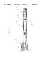
- FIG. 2is an external side view of the camera showing the handpiece and the end of the connecting cord.
- FIG. 3Ais a cross-sectional view of a distal fragmented portion of the camera taken from section line 3A--3A in FIG. 3B.
- FIG. 3Bis a bottom view of the distal fragmented portion of the camera.
- FIG. 4is a cross-sectional view of the camera, showing detail in the median portion.
- FIG. 5is a view of the proximal portion of the handpiece and the distal portion of the connecting cord assembly.
- FIGS. 6A-6Dshow alternate arrangements of lamps about the imaging window.
- FIG. 7is a block diagram of a strobed illumination system for the camera.
- FIG. 1shows a dental video camera system including a handpiece 200 and an image processing system 202.
- the handpiece 200is connected to the image processing system 202 via a connecting cord 201.
- FIG. 2shows the handpiece 200 which has a distal end 1, a median section 2, a focusing ring 3, and a mini circular connector 4 at the proximal end of the handpiece.
- the connector 4mates with a matching mini circular connector 5, which terminates the video cable 6.
- Signals originating from an image sensor (not shown) housed inside the handpiece 200travel through the connector 4, the connector 5, and the video cable 6 on their way to the image processing system 202 (shown in FIG. 1).
- FIGS. 3A and 3Bshow details of the distal end 1 of one embodiment of the handpiece, which includes an imaging window 12 and light sources 10a and 10b.
- the imaging windowreceives light reflected by the subject.
- the light sources 10a and 10bwhich are located distal to the imaging window 12 and are covered by a protective glass shield 11, are aimed so that they will provide illumination for subjects located below the window.
- a prism 13is located within the distal end of the handpiece 1, angled in relation to the imaging window 12 to direct the light arriving through the imaging window in the direction of the proximal end of the handpiece.
- a single piece of materialmay be used as both the window and the shield. In this configuration, the material would have a window portion and a shield portion distal to the window portion.
- a wide variety of lampsmay be used.
- a low-power, long life lampis preferable to save power and minimize service calls and system down time.
- a suitable lampis an incandescent light bulb, such as Gilway Technical Lamp #4115.
- Another exampleis a "white LED".
- This white LEDcould comprise, for example, a short-wavelength LED combined together with a phosphorescent coating, such as Nichia America #NSCW-100.
- the "white LED”could also comprise, for example, a set of three single color LEDs (e.g., red, green, and blue), mounted in a single package, such as Nichia America #NSCM-310. While two lamps are depicted in the figure, any number of lamps may be used. In addition to generating light, the lamps also generate some heat. This is advantageous in dental applications, because it helps clear away condensation that could form from a patient's breathing on a cold instrument.
- the diameter of the housingcan be minimized. This allows the present invention to be contained within a slimmer housing, as compared to prior art cameras which have light sources positioned above the imaging window, such as the one described in U.S. Pat. No. 4,575,805 (Moermann et al.).
- a slimmer deviceis advantageous for dental use.
- FIGS. 6A, 6B, and 6Dshow a number of light sources 10 arranged on three sides of the imaging window 12.
- FIG. 6Cshows a number of light sources arranged on four sides of the imaging window. Numerous other light source arrangements can be readily envisioned.
- Aiming of the light sourcesdepends on both the arrangement of the light sources around the window and the type of light source used. For example, when incandescent lamps are used in the configuration shown in FIG. 3B, the lamps should be angled as shown in the figure so that the light is directed back towards the proximal end. When LEDs are used in any of the configurations depicted in FIGS. 6A-6D, the LEDs can be aimed perpendicular to the surface of the instrument, because the light is sufficiently diffused to illuminate the subject.
- FIG. 4shows details of the median section 2 of the handpiece, which houses the lens system 22, the image sensor 23, and the focusing mechanism 3.
- the lens system 22is preferably a fixed-focus lens system.
- the image sensor 23is preferably either a CCD (charge coupled device) or an APS (active pixel sensor array).
- the lens system 22is located in the distal portion of the median section 2, proximal to the distal end of the handpiece 1.
- the movable image sensor 23is located proximal to the fixed lens system 22.
- the lens system 22transmits the light arriving from the distal end of the handpiece 1 to the active surface of the image sensor 23.
- the lens system 22may be replaced by another type of light direction means including, for example, a mirror, a prism, and an optical fiber.
- the movable image sensor 23is controlled by a plunger system which is attached to the focusing ring 3.
- the focusing ring 3can be manually rotated into any of a plurality of detented positions that correspond to a plurality of image sensor positions.
- One preferred embodimentuses four detented positions.
- the image sensorwhich is mechanically coupled to the plunger system, is moved nearer to or farther from the fixed lens system 22 along a proximal-to-distal axis, depending on the degree of rotation.
- Each of these positionshas an associated focal setting and depth of field.
- the approximate focal range settingsare: (1) 1 to 6 mm; (2) 5-15 mm; (3) 12-25 mm; and (4) 180 mm- ⁇ . This selection of focal range settings is optimized for dental imaging by minimizing the required amount of manipulation while maximizing image quality and ease of use.
- the total range of movement of the image sensor needed to obtain these focal settingsis approximately 2 mm. If the amount of light supplied to the subject is increased, the depth of field can be extended by reducing the aperture of the lens. This would allow a reduction in the number of focus ranges.
- FIG. 5shows a sectional view of the proximal end of the handpiece 200, as well as the distal end of the connecting cord assembly 201.
- the mini circular connector 4 at the proximal end of the handpiece 200mates with the connector 5 on the connecting cord assembly 201.
- the connectorscan be mated and released quickly.
- a suitable connector pair for this purposeincludes, for example, parts Nos. HR25-9P-16 and HR25-9R-16 made by Hirose Electric.
- the connecting cord assembly 201includes a video cable 6 which is preferably flexible and lightweight.
- the connecting cord assemblytransmits the video image acquired by the image sensor in the handpiece to the image processing system (shown in FIG. 1).
- Some preprocessingmay be performed by known means in the handpiece 200 before the image signals are sent to the image processing system.
- the image processing system 202may be implemented in hardware, software or a combination of both.
- Two image processing settingsmay be selected: intraoral and extraoral. These settings correct for the quality and amount of light available and allow for realistic images to be acquired in both intraoral and extraoral locations, because ambient light is qualitatively different from lamp light.
- This featureis implemented by storing two different white balances in the image processing system (one for the extraoral setting and one for the intraoral setting) and processing the image using the appropriate stored white balance.
- the white balance processingadjusts the levels of the red, green, and blue components of the image to create an image in which white objects are perceived as being white.
- a preferred approach of implementing the white balance processinguses the Panasonic GP-KS 162 CB camera control unit (CCU) together with a Panasonic GP-KS 462HM CCD.
- the CCUincludes circuitry to interface with the CCD, white balance processing, and circuitry to generate an NTSC video signal.
- the CCUcan store two white balances corresponding to two different types of light. For example, the white balance settings for the ambient light coming from a dentist's overhead light and from the camera's light source can be stored. When the dentist uses the camera, the appropriate white balance setting can be selected instantaneously without recalibrating the white balance for each exposure.
- the preferred CCUcan compensate for white balances ranging from 2,200-10,000 ° K. of color temperature. Incandescent lamps and both types and white LEDs are available within that temperature range. For those parts that have a wide range of color temperature, samples with the appropriate color temperature should be selected.
- the light source located in the head of the cameracan be automatically switched on. In this mode, the image is processed using a stored white balance corresponding to the quality of the lamps which provide illumination (e.g., the incandescent bulbs or LEDs described above).
- a stored white balancecorresponding to the quality of the lamps which provide illumination (e.g., the incandescent bulbs or LEDs described above).
- ambient lightis available.
- the light sourcecan be automatically turned off. Due to the presence of ambient light, a different stored white balance is used to process the image.
- the embodiments described aboveinvolve illuminating the subject with white light and detecting the light using a sensor that is sensitive to white light.
- An alternative embodimentuses a monochromatic sensor and strobes of different colored monochromatic light to attain the same effect as white illumination.
- FIG. 7depicts an embodiment that uses this strobed configuration.
- the subjectinstead of illuminating the subject with white light, the subject is strobed with each of the components of white light (red, green, and blue) sequentially.
- the output from the image sensoris captured.
- the image sensor outputs from the three strobe periodsare then combined by a signal processor to form a standard RGB video signal.
- the clock generator 38provides timing signals to synchronize the circuit.
- the LED sequencer 36receives a clock signal from the clock generator 38, and turns on each of the LEDs 33-35 in turn, in three phrases. During the first phase, the LED sequencer 36 turns on the red LED 33. During the second phase, the LED sequencer 36 turns on the green LED 34. During the third phase, the LED sequencer 36 turns on the blue LED 35. This sequence of phases repeats continuously.
- the clock generator 38also sends signals to the image sensor driver 37.
- the image sensor 32receives light that originated from one of the LEDs 33-35, bounced off a subject 31, and onto the image sensor 32. The output of the image sensor is received by the image sensor driver 37.
- the red LED 33is illuminated, the image sensor will capture an image of the subject 31 illuminated by red light.
- the green LED 34is illuminated, the image sensor will capture an image of the subject illuminated by green light.
- the blue LED 34is illuminated, the image sensor will capture an image of the subject illuminated by blue light.
- the signal processor 39receives these three images from the image sensor driver 37, together with synchronizing signals from the clock generator 38.
- the signal processorcombines three image signals into ordinary RGB signals which are provided to a video signal interface 40.
- the clock generator 38provides horizontal and vertical synchronization signals to the video signal interface 40, which outputs a video signal in a standard format such as NTSC, PAL, etc.
- red lightmay be used during the first phase
- red and blue lightmay be used during the second phase.
- the blue componentmay be computed by subtraction.
- other combinations of colorsmay be used as well.
- a monochromatic image sensormay be used in place of a full color image sensor. This is advantageous because monochromatic image sensors are significantly less expensive.
- the frame rate at the image sensormust be tripled (i.e., to 90 frames per second).
- one red, one green and one blue imageis captured by the image sensor in each 1/30 second interval.
- the signal processor 39includes white balance circuitry that adjusts the proportions of the red, green, and blue images to produce a color-corrected image.
- the LED sequencer 36can vary the brightness and/or duration of the red, blue, and green illumination to achieve color corrected images.
- the combination of features described aboveallows the camera to be lighter, more portable, consume less power, and to produce a more authentic image than previous cameras.
Landscapes
- Engineering & Computer Science (AREA)
- Multimedia (AREA)
- Signal Processing (AREA)
- Endoscopes (AREA)
Abstract
Description
This invention relates to the field of video imaging and, more specifically, to a video imaging apparatus for use in dental imaging.
Video imaging cameras have been used for obtaining images in dentistry for some time. One example of an existing system can be found in U.S. Pat. No. 5,523,782 (Williams), which describes a video dental camera that includes a light source, a CCD, and an adjustable focus lens system. Other examples of existing system can be found in U.S. Pat. No. 4,575,805 (Moermann et al.), and in U.S. Pat. No. 5,527,261 (Monroe et al.).
Until now, however, prior dental cameras did not rapidly and automatically compensate for the different white balances encountered (a) when the camera provides its own illumination and (b) when the camera is used with ambient illumination.
The present invention advantageously avoids the aforementioned drawback by compensating for the different white balances that may be encountered by a dental video camera.
According to one aspect of the invention, a dental imaging apparatus is provided. The apparatus includes a housing and an image sensor with an active surface. The image sensor is mounted in the housing so that the active surface receives light reflected from a dental subject. The apparatus also includes a lamp for illuminating the dental subject and an image processor for receiving image signals from an image sensor output and processing the image signals in accordance with either a first stored white balance related to a characteristic of the lamp illumination or a second stored white balance.
According to another aspect of the invention, a method of obtaining an image of a dental subject using an apparatus including a lamp and an image sensor is provided. The method includes the steps of receiving image signals from the image sensor and selecting a first or a second mode of operation. The image signals are processed in accordance with a first stored white balance related to a characteristic of the lamp when the first mode is selected, and in accordance with a second stored white balance when the second mode is selected.
According to another aspect of the invention, an apparatus for obtaining an image of a dental subject is provided. The apparatus includes a lamp, an image sensor, and means for receiving image signals from the image sensor. The apparatus also includes means for selecting a first or a second mode of operation and means for processing the image signals in accordance with a first stored white balance when the first mode is selected, and a second stored white balance when the second mode is selected. The first stored white balance is related to a characteristic of the lamp.
FIG. 1 depicts an embodiment of an electronic video dental camera and image processing system in accordance with the present invention.
FIG. 2 is an external side view of the camera showing the handpiece and the end of the connecting cord.
FIG. 3A is a cross-sectional view of a distal fragmented portion of the camera taken fromsection line 3A--3A in FIG. 3B.
FIG. 3B is a bottom view of the distal fragmented portion of the camera.
FIG. 4 is a cross-sectional view of the camera, showing detail in the median portion.
FIG. 5 is a view of the proximal portion of the handpiece and the distal portion of the connecting cord assembly.
FIGS. 6A-6D show alternate arrangements of lamps about the imaging window.
FIG. 7 is a block diagram of a strobed illumination system for the camera.
FIG. 1 shows a dental video camera system including ahandpiece 200 and animage processing system 202. Thehandpiece 200 is connected to theimage processing system 202 via a connectingcord 201.
FIG. 2 shows thehandpiece 200 which has a distal end 1, amedian section 2, a focusingring 3, and a minicircular connector 4 at the proximal end of the handpiece. Theconnector 4 mates with a matching minicircular connector 5, which terminates thevideo cable 6. Signals originating from an image sensor (not shown) housed inside thehandpiece 200 travel through theconnector 4, theconnector 5, and thevideo cable 6 on their way to the image processing system 202 (shown in FIG. 1).
FIGS. 3A and 3B show details of the distal end 1 of one embodiment of the handpiece, which includes animaging window 12 and light sources 10a and 10b. The imaging window receives light reflected by the subject. The light sources 10a and 10b, which are located distal to theimaging window 12 and are covered by a protective glass shield 11, are aimed so that they will provide illumination for subjects located below the window. Aprism 13 is located within the distal end of the handpiece 1, angled in relation to theimaging window 12 to direct the light arriving through the imaging window in the direction of the proximal end of the handpiece. Of course, instead of using anindividual imaging window 12 and shield 11, as depicted in the figure, a single piece of material may be used as both the window and the shield. In this configuration, the material would have a window portion and a shield portion distal to the window portion.
A wide variety of lamps may be used. A low-power, long life lamp is preferable to save power and minimize service calls and system down time. One example of a suitable lamp is an incandescent light bulb, such as Gilway Technical Lamp #4115. Another example is a "white LED". This white LED could comprise, for example, a short-wavelength LED combined together with a phosphorescent coating, such as Nichia America #NSCW-100. The "white LED" could also comprise, for example, a set of three single color LEDs (e.g., red, green, and blue), mounted in a single package, such as Nichia America #NSCM-310. While two lamps are depicted in the figure, any number of lamps may be used. In addition to generating light, the lamps also generate some heat. This is advantageous in dental applications, because it helps clear away condensation that could form from a patient's breathing on a cold instrument.
By locating the lamps in the distal end of the handpiece, distal to the imaging window, and angling the lamps so as to provide direct illumination of the object being imaged, the diameter of the housing can be minimized. This allows the present invention to be contained within a slimmer housing, as compared to prior art cameras which have light sources positioned above the imaging window, such as the one described in U.S. Pat. No. 4,575,805 (Moermann et al.). A slimmer device is advantageous for dental use.
Alternative light source arrangements may also be used. For example, FIGS. 6A, 6B, and 6D show a number oflight sources 10 arranged on three sides of theimaging window 12. FIG. 6C shows a number of light sources arranged on four sides of the imaging window. Numerous other light source arrangements can be readily envisioned.
Aiming of the light sources depends on both the arrangement of the light sources around the window and the type of light source used. For example, when incandescent lamps are used in the configuration shown in FIG. 3B, the lamps should be angled as shown in the figure so that the light is directed back towards the proximal end. When LEDs are used in any of the configurations depicted in FIGS. 6A-6D, the LEDs can be aimed perpendicular to the surface of the instrument, because the light is sufficiently diffused to illuminate the subject.
FIG. 4 shows details of themedian section 2 of the handpiece, which houses thelens system 22, theimage sensor 23, and the focusingmechanism 3. Thelens system 22 is preferably a fixed-focus lens system. Theimage sensor 23 is preferably either a CCD (charge coupled device) or an APS (active pixel sensor array).
Thelens system 22 is located in the distal portion of themedian section 2, proximal to the distal end of the handpiece 1. Themovable image sensor 23 is located proximal to the fixedlens system 22. Thelens system 22 transmits the light arriving from the distal end of the handpiece 1 to the active surface of theimage sensor 23. Thelens system 22 may be replaced by another type of light direction means including, for example, a mirror, a prism, and an optical fiber.
Themovable image sensor 23 is controlled by a plunger system which is attached to the focusingring 3. Preferably, the focusingring 3 can be manually rotated into any of a plurality of detented positions that correspond to a plurality of image sensor positions.
One preferred embodiment uses four detented positions. When the focusingring 3 is rotated into each of the four various positions, the image sensor, which is mechanically coupled to the plunger system, is moved nearer to or farther from the fixedlens system 22 along a proximal-to-distal axis, depending on the degree of rotation. Each of these positions has an associated focal setting and depth of field. Most preferably, the approximate focal range settings are: (1) 1 to 6 mm; (2) 5-15 mm; (3) 12-25 mm; and (4) 180 mm-∞. This selection of focal range settings is optimized for dental imaging by minimizing the required amount of manipulation while maximizing image quality and ease of use. For a system using a 3.65 mm×2.74 mm rectangular CCD image sensor and a lens with a focal length of 4.50 mm, the total range of movement of the image sensor needed to obtain these focal settings is approximately 2 mm. If the amount of light supplied to the subject is increased, the depth of field can be extended by reducing the aperture of the lens. This would allow a reduction in the number of focus ranges.
FIG. 5 shows a sectional view of the proximal end of thehandpiece 200, as well as the distal end of the connectingcord assembly 201. The minicircular connector 4 at the proximal end of thehandpiece 200 mates with theconnector 5 on the connectingcord assembly 201. Preferably, the connectors can be mated and released quickly. A suitable connector pair for this purpose includes, for example, parts Nos. HR25-9P-16 and HR25-9R-16 made by Hirose Electric. The connectingcord assembly 201 includes avideo cable 6 which is preferably flexible and lightweight. When theconnector 4 is mated with theconnector 5, the connecting cord assembly transmits the video image acquired by the image sensor in the handpiece to the image processing system (shown in FIG. 1). Some preprocessing (including, e.g., preamplification) may be performed by known means in thehandpiece 200 before the image signals are sent to the image processing system.
Returning to FIG. 1, theimage processing system 202 may be implemented in hardware, software or a combination of both. Two image processing settings may be selected: intraoral and extraoral. These settings correct for the quality and amount of light available and allow for realistic images to be acquired in both intraoral and extraoral locations, because ambient light is qualitatively different from lamp light. This feature is implemented by storing two different white balances in the image processing system (one for the extraoral setting and one for the intraoral setting) and processing the image using the appropriate stored white balance. The white balance processing adjusts the levels of the red, green, and blue components of the image to create an image in which white objects are perceived as being white.
A preferred approach of implementing the white balance processing uses the Panasonic GP-KS 162 CB camera control unit (CCU) together with a Panasonic GP-KS 462HM CCD. The CCU includes circuitry to interface with the CCD, white balance processing, and circuitry to generate an NTSC video signal. The CCU can store two white balances corresponding to two different types of light. For example, the white balance settings for the ambient light coming from a dentist's overhead light and from the camera's light source can be stored. When the dentist uses the camera, the appropriate white balance setting can be selected instantaneously without recalibrating the white balance for each exposure.
The preferred CCU can compensate for white balances ranging from 2,200-10,000 ° K. of color temperature. Incandescent lamps and both types and white LEDs are available within that temperature range. For those parts that have a wide range of color temperature, samples with the appropriate color temperature should be selected.
In the case of intraoral imaging, very little ambient light is available. When the camera is switched to the intraoral setting, the light source located in the head of the camera can be automatically switched on. In this mode, the image is processed using a stored white balance corresponding to the quality of the lamps which provide illumination (e.g., the incandescent bulbs or LEDs described above). In the case of extraoral imaging, ambient light is available. When the camera is switched to the extraoral setting, the light source can be automatically turned off. Due to the presence of ambient light, a different stored white balance is used to process the image.
The embodiments described above involve illuminating the subject with white light and detecting the light using a sensor that is sensitive to white light. An alternative embodiment uses a monochromatic sensor and strobes of different colored monochromatic light to attain the same effect as white illumination.
FIG. 7 depicts an embodiment that uses this strobed configuration. In this embodiment, instead of illuminating the subject with white light, the subject is strobed with each of the components of white light (red, green, and blue) sequentially. During each strobe period, the output from the image sensor is captured. The image sensor outputs from the three strobe periods are then combined by a signal processor to form a standard RGB video signal.
Theclock generator 38 provides timing signals to synchronize the circuit. TheLED sequencer 36 receives a clock signal from theclock generator 38, and turns on each of the LEDs 33-35 in turn, in three phrases. During the first phase, theLED sequencer 36 turns on thered LED 33. During the second phase, theLED sequencer 36 turns on thegreen LED 34. During the third phase, theLED sequencer 36 turns on theblue LED 35. This sequence of phases repeats continuously.
Theclock generator 38 also sends signals to theimage sensor driver 37. Theimage sensor 32 receives light that originated from one of the LEDs 33-35, bounced off a subject 31, and onto theimage sensor 32. The output of the image sensor is received by theimage sensor driver 37. When thered LED 33 is illuminated, the image sensor will capture an image of the subject 31 illuminated by red light. When thegreen LED 34 is illuminated, the image sensor will capture an image of the subject illuminated by green light. Similarly, when theblue LED 34 is illuminated, the image sensor will capture an image of the subject illuminated by blue light.
Thesignal processor 39 receives these three images from theimage sensor driver 37, together with synchronizing signals from theclock generator 38. The signal processor combines three image signals into ordinary RGB signals which are provided to avideo signal interface 40. Theclock generator 38 provides horizontal and vertical synchronization signals to thevideo signal interface 40, which outputs a video signal in a standard format such as NTSC, PAL, etc.
It is also possible to implement an equivalent system by illuminating the subject with more than one color at a time. For example, red light may be used during the first phase, and red and blue light may be used during the second phase. Then, the blue component may be computed by subtraction. Of course, other combinations of colors may be used as well.
By using this system, a monochromatic image sensor may be used in place of a full color image sensor. This is advantageous because monochromatic image sensors are significantly less expensive. In this configuration, to achieve a standard video frame rate of 30 frames per second, the frame rate at the image sensor must be tripled (i.e., to 90 frames per second). As a result, one red, one green and one blue image is captured by the image sensor in each 1/30 second interval. These images are stored in thesignal processor 39 and output at the standard frame rate.
Preferably, thesignal processor 39 includes white balance circuitry that adjusts the proportions of the red, green, and blue images to produce a color-corrected image. Alternatively, theLED sequencer 36 can vary the brightness and/or duration of the red, blue, and green illumination to achieve color corrected images.
The combination of features described above allows the camera to be lighter, more portable, consume less power, and to produce a more authentic image than previous cameras.
While the present invention has been described above in terms of specific embodiments, it is to be understood that the invention is not limited to the disclosed embodiments. On the contrary, the present invention is intended to cover various modifications and equivalent structures included within the spirit and scope of the appended claims.
Claims (20)
1. A dental imaging apparatus comprising:
a housing;
an image sensor having an active surface, said image sensor being mounted in said housing so that the active surface receives light reflected from a dental subject;
a lamp, mounted in said housing, for illuminating the dental subject when said lamp is on;
a switch that selects between an intraoral mode in which said lamp is on and an extraoral mode in which said lamp is off; and
an image processor that receives image signals from said image sensor and processes the image signals in accordance with either a first stored white balance when said switch is set to select the intraoral mode or a second stored white balance when said switch is set to select the extraoral mode.
2. The dental imaging apparatus according to claim 1, wherein the first stored white balance is optimized for the light provided by said lamp.
3. The dental imaging apparatus according to claim 1, wherein the second stored white balance is optimized for ambient light.
4. The dental camera imaging apparatus according to claim 1, wherein said lamp comprises an incandescent light bulb.
5. The dental imaging apparatus according to claim 1, wherein said lamp comprises a plurality of different colored LEDS.
6. The dental imaging apparatus according to claim 1, wherein said lamp comprises an LED and a phosphorescent coating.
7. The dental imaging apparatus according to claim 1, wherein said image sensor comprises at least one of a CCD and an APS.
8. The dental imaging apparatus according to claim 1, further comprising a quick release circular connector mounted on said housing, said connector being electrically connected to the output of said image sensor, said connector being capable of mating with a compatible connector for sending signals to said image processor.
9. A method of obtaining an image of a dental subject using an apparatus including a lamp and an image sensor, the method comprising the steps of:
receiving image signals from the image sensor;
selecting between an intraoral mode in which said lamp is on and an extraoral mode in which said lamp is off;
processing the image signals in accordance with a first stored white balance when the intraoral mode is selected; and
processing the image signals in accordance with a second stored white balance when the extraoral mode is selected.
10. The method according to claim 9, further comprising the step of causing the lamp to illuminate the dental subject when the first mode is selected.
11. The method according to claim 10, wherein the first stored white balance is optimized for the light provided by the lamp.
12. The method according to claim 10, wherein the second stored white balance is optimized for ambient light.
13. An apparatus for obtaining an image of a dental subject comprising:
a lamp;
an image sensor;
means for receiving image signals from said image sensor;
means for selecting between an intraoral mode in which said lamp is on and an extraoral mode in which said lamp is off; and
means for processing the image signals in accordance with a first stored white balance when the intraoral mode is selected, and processing the image signals in accordance with a second stored white balance when the extraoral mode is selected.
14. The dental imaging apparatus according to claim 13, wherein the first stored white balance is optimized for the light provided by said lamp.
15. The dental imaging apparatus according to claim 13, wherein the second stored white balance is optimized for ambient light.
16. The dental imaging apparatus according to claim 13, wherein said lamp comprises an incandescent light bulb.
17. The dental imaging apparatus according to claim 13, wherein said lamp comprises a plurality of different colored LEDs.
18. The dental imaging apparatus according to claim 13, wherein said lamp comprises an LED and a phosphorescent coating.
19. The dental imaging apparatus according to claim 13, wherein said image sensor comprises at least one of a CCD and an APS.
20. The dental imaging apparatus according to claim 13, further comprising a quick release circular connector mounted on said housing, said connector being electrically connected to the output of said image sensor, said connector being capable of mating with a compatible connector for sending signals to said image processor.
Priority Applications (1)
| Application Number | Priority Date | Filing Date | Title |
|---|---|---|---|
| US08/873,805US6002424A (en) | 1997-06-12 | 1997-06-12 | Dental imaging system with white balance compensation |
Applications Claiming Priority (1)
| Application Number | Priority Date | Filing Date | Title |
|---|---|---|---|
| US08/873,805US6002424A (en) | 1997-06-12 | 1997-06-12 | Dental imaging system with white balance compensation |
Publications (1)
| Publication Number | Publication Date |
|---|---|
| US6002424Atrue US6002424A (en) | 1999-12-14 |
Family
ID=25362359
Family Applications (1)
| Application Number | Title | Priority Date | Filing Date |
|---|---|---|---|
| US08/873,805Expired - LifetimeUS6002424A (en) | 1997-06-12 | 1997-06-12 | Dental imaging system with white balance compensation |
Country Status (1)
| Country | Link |
|---|---|
| US (1) | US6002424A (en) |
Cited By (28)
| Publication number | Priority date | Publication date | Assignee | Title |
|---|---|---|---|---|
| US6181369B1 (en)* | 1997-01-09 | 2001-01-30 | Matsushita Electric Industrial Co., Ltd. | Videoscope for dental or other use |
| US20010007470A1 (en)* | 1999-12-31 | 2001-07-12 | Nokia Mobile Phones Ltd. | Measurement of illumination conditions |
| US20010010760A1 (en)* | 2000-01-28 | 2001-08-02 | Masashi Saito, Hiroyuki Oguni, Yoshiteru Okada And Hiroshi Okada | Intraoral imaging camera system |
| US6404984B1 (en)* | 1998-11-19 | 2002-06-11 | Sony Corporation | Lighted camera for dental examinations and method of using the same |
| WO2002082820A1 (en)* | 2001-04-07 | 2002-10-17 | Dentsply International, Inc. | Dental video imaging system |
| USD467660S1 (en) | 2001-11-07 | 2002-12-24 | Cygnus Technologies, L.L.C. | Dental imaging apparatus |
| USD468429S1 (en) | 2001-03-26 | 2003-01-07 | Kaltenbach & Voight Gmbh | Intraoral camera |
| WO2003036944A1 (en)* | 2001-10-19 | 2003-05-01 | Cobra Electronic Gmbh | Miniaturized camera equipped with a tubular or bar-shaped housing |
| US6594539B1 (en)* | 1999-03-29 | 2003-07-15 | Genex Technologies, Inc. | Three-dimensional dental imaging method and apparatus having a reflective member |
| US20030160889A1 (en)* | 2002-02-22 | 2003-08-28 | Gerald Angeli | Camera with led lighting source for illuminating a scene to be photographed |
| US20040117052A1 (en)* | 1999-03-29 | 2004-06-17 | Geng Z. Jason | Sanitary sleeve or tip for intra-oral three-dimensional camera |
| US20040156626A1 (en)* | 2001-05-26 | 2004-08-12 | Michael Thoms | Dental or endoscopic camera |
| US20040184643A1 (en)* | 2003-03-21 | 2004-09-23 | Stantchev Gueorgui H. | Methods and apparatus for imaging |
| US20040252188A1 (en)* | 2003-03-21 | 2004-12-16 | Stantchev Gueorgui H. | Methods and apparatus for imaging |
| WO2004069078A3 (en)* | 2003-02-03 | 2005-02-24 | Schick Technologies Inc | Dental camera utilizing multiple lenses |
| US6958766B2 (en) | 2000-04-06 | 2005-10-25 | Gendex Corporation | Dental video imaging system |
| US20050254625A1 (en)* | 2004-05-11 | 2005-11-17 | Schick Technologies Inc. | Installation of an x-ray receiver |
| US20070225557A1 (en)* | 2006-03-22 | 2007-09-27 | Industrial Technology Research Institute | Medical inspection devices |
| US20080037247A1 (en)* | 2006-08-09 | 2008-02-14 | Olympus Medical Systems Corp. | Light source apparatus |
| US20100150469A1 (en)* | 2002-01-04 | 2010-06-17 | Warner Bros. Entertainment Inc. | Registration of Separations |
| US20100238279A1 (en)* | 2007-03-16 | 2010-09-23 | Durr Dental Ag | Diagnostic Camera and Attachment for the Implementation Thereof |
| US20110149058A1 (en)* | 2009-12-21 | 2011-06-23 | Rongguang Liang | Intra-oral camera with polarized and unpolarized light |
| US8016470B2 (en) | 2007-10-05 | 2011-09-13 | Dental Equipment, Llc | LED-based dental exam lamp with variable chromaticity |
| USD674091S1 (en)* | 2011-12-20 | 2013-01-08 | 3M Innovative Properties Company | Intra-oral scanning wand |
| USD722164S1 (en) | 2014-02-13 | 2015-02-03 | 3M Innovative Properties Company | Intra-oral scanning wand |
| US9241128B2 (en) | 2013-02-14 | 2016-01-19 | Warner Bros. Entertainment Inc. | Video conversion technology |
| US10238277B2 (en)* | 2016-05-26 | 2019-03-26 | Dental Smartmirror, Inc. | Curing dental material using lights affixed to an intraoral mirror, and applications thereof |
| US20190282342A1 (en)* | 2018-03-19 | 2019-09-19 | 3D Imaging and Simulation Corp. Americas | Intraoral scanner and computing system for capturing images and generating three-dimensional models |
Citations (22)
| Publication number | Priority date | Publication date | Assignee | Title |
|---|---|---|---|---|
| US1704397A (en)* | 1925-01-16 | 1929-03-05 | Oscar H Pieper | Surgical instrument |
| US2038911A (en)* | 1935-06-19 | 1936-04-28 | Stutz Adam | Dental light |
| US2788390A (en)* | 1952-10-16 | 1957-04-09 | Sheldon Edward Emanuel | Device for examination of inaccessible parts |
| US3593055A (en)* | 1969-04-16 | 1971-07-13 | Bell Telephone Labor Inc | Electro-luminescent device |
| US4230453A (en)* | 1979-04-11 | 1980-10-28 | Litton Industrial Products Inc. | Light assembly for use with a dental handpiece |
| US4575805A (en)* | 1980-12-24 | 1986-03-11 | Moermann Werner H | Method and apparatus for the fabrication of custom-shaped implants |
| US4858001A (en)* | 1987-10-08 | 1989-08-15 | High-Tech Medical Instrumentation, Inc. | Modular endoscopic apparatus with image rotation |
| US4926258A (en)* | 1987-10-20 | 1990-05-15 | Olympus Optical Co., Ltd. | Electronic endoscope apparatus capable of driving solid state imaging devices having different characteristics |
| US4994910A (en)* | 1989-07-06 | 1991-02-19 | Acuimage Corporation | Modular endoscopic apparatus with probe |
| US5124797A (en)* | 1990-07-20 | 1992-06-23 | New Image Industries, Inc. | Modular view lens attachment for micro video imaging camera |
| US5267857A (en)* | 1993-02-12 | 1993-12-07 | A-Dec, Inc. | Brightness control system for dental handpiece light |
| US5363135A (en)* | 1992-04-21 | 1994-11-08 | Inglese Jean Marc | Endoscope having a semi-conductor element illumination arrangement |
| US5408263A (en)* | 1992-06-16 | 1995-04-18 | Olympus Optical Co., Ltd. | Electronic endoscope apparatus |
| US5429502A (en)* | 1987-03-05 | 1995-07-04 | Fuji Optical Systems, Inc. | Electronic video dental camera |
| US5487661A (en)* | 1993-10-08 | 1996-01-30 | Dentsply International, Inc. | Portable dental camera and system |
| US5512036A (en)* | 1994-03-15 | 1996-04-30 | Welch Allyn, Inc. | Dental imaging system |
| US5523782A (en)* | 1992-09-11 | 1996-06-04 | Williams; Ronald R. | Dental video camera with an adjustable iris |
| US5527261A (en)* | 1994-08-18 | 1996-06-18 | Welch Allyn, Inc. | Remote hand-held diagnostic instrument with video imaging |
| US5594433A (en)* | 1995-08-09 | 1997-01-14 | Terlep; Stephen K. | Omni-directional LED lamps |
| US5685821A (en)* | 1992-10-19 | 1997-11-11 | Arthrotek | Method and apparatus for performing endoscopic surgical procedures |
| US5691772A (en)* | 1992-11-25 | 1997-11-25 | Nikon Corporation | White balance adjustment device |
| US5808681A (en)* | 1995-04-13 | 1998-09-15 | Ricoh Company, Ltd. | Electronic still camera |
- 1997
- 1997-06-12USUS08/873,805patent/US6002424A/ennot_activeExpired - Lifetime
Patent Citations (23)
| Publication number | Priority date | Publication date | Assignee | Title |
|---|---|---|---|---|
| US1704397A (en)* | 1925-01-16 | 1929-03-05 | Oscar H Pieper | Surgical instrument |
| US2038911A (en)* | 1935-06-19 | 1936-04-28 | Stutz Adam | Dental light |
| US2788390A (en)* | 1952-10-16 | 1957-04-09 | Sheldon Edward Emanuel | Device for examination of inaccessible parts |
| US3593055A (en)* | 1969-04-16 | 1971-07-13 | Bell Telephone Labor Inc | Electro-luminescent device |
| US4230453A (en)* | 1979-04-11 | 1980-10-28 | Litton Industrial Products Inc. | Light assembly for use with a dental handpiece |
| US4575805A (en)* | 1980-12-24 | 1986-03-11 | Moermann Werner H | Method and apparatus for the fabrication of custom-shaped implants |
| US5429502A (en)* | 1987-03-05 | 1995-07-04 | Fuji Optical Systems, Inc. | Electronic video dental camera |
| US4858001B1 (en)* | 1987-10-08 | 1992-06-30 | High Tech Medical Instrumentat | |
| US4858001A (en)* | 1987-10-08 | 1989-08-15 | High-Tech Medical Instrumentation, Inc. | Modular endoscopic apparatus with image rotation |
| US4926258A (en)* | 1987-10-20 | 1990-05-15 | Olympus Optical Co., Ltd. | Electronic endoscope apparatus capable of driving solid state imaging devices having different characteristics |
| US4994910A (en)* | 1989-07-06 | 1991-02-19 | Acuimage Corporation | Modular endoscopic apparatus with probe |
| US5124797A (en)* | 1990-07-20 | 1992-06-23 | New Image Industries, Inc. | Modular view lens attachment for micro video imaging camera |
| US5363135A (en)* | 1992-04-21 | 1994-11-08 | Inglese Jean Marc | Endoscope having a semi-conductor element illumination arrangement |
| US5408263A (en)* | 1992-06-16 | 1995-04-18 | Olympus Optical Co., Ltd. | Electronic endoscope apparatus |
| US5523782A (en)* | 1992-09-11 | 1996-06-04 | Williams; Ronald R. | Dental video camera with an adjustable iris |
| US5685821A (en)* | 1992-10-19 | 1997-11-11 | Arthrotek | Method and apparatus for performing endoscopic surgical procedures |
| US5691772A (en)* | 1992-11-25 | 1997-11-25 | Nikon Corporation | White balance adjustment device |
| US5267857A (en)* | 1993-02-12 | 1993-12-07 | A-Dec, Inc. | Brightness control system for dental handpiece light |
| US5487661A (en)* | 1993-10-08 | 1996-01-30 | Dentsply International, Inc. | Portable dental camera and system |
| US5512036A (en)* | 1994-03-15 | 1996-04-30 | Welch Allyn, Inc. | Dental imaging system |
| US5527261A (en)* | 1994-08-18 | 1996-06-18 | Welch Allyn, Inc. | Remote hand-held diagnostic instrument with video imaging |
| US5808681A (en)* | 1995-04-13 | 1998-09-15 | Ricoh Company, Ltd. | Electronic still camera |
| US5594433A (en)* | 1995-08-09 | 1997-01-14 | Terlep; Stephen K. | Omni-directional LED lamps |
Cited By (47)
| Publication number | Priority date | Publication date | Assignee | Title |
|---|---|---|---|---|
| US6181369B1 (en)* | 1997-01-09 | 2001-01-30 | Matsushita Electric Industrial Co., Ltd. | Videoscope for dental or other use |
| US6404984B1 (en)* | 1998-11-19 | 2002-06-11 | Sony Corporation | Lighted camera for dental examinations and method of using the same |
| US6594539B1 (en)* | 1999-03-29 | 2003-07-15 | Genex Technologies, Inc. | Three-dimensional dental imaging method and apparatus having a reflective member |
| US7099732B2 (en) | 1999-03-29 | 2006-08-29 | Genex Technologies, Inc. | Sanitary sleeve or tip for intra-oral three-dimensional camera |
| US20040117052A1 (en)* | 1999-03-29 | 2004-06-17 | Geng Z. Jason | Sanitary sleeve or tip for intra-oral three-dimensional camera |
| US20010007470A1 (en)* | 1999-12-31 | 2001-07-12 | Nokia Mobile Phones Ltd. | Measurement of illumination conditions |
| US20010010760A1 (en)* | 2000-01-28 | 2001-08-02 | Masashi Saito, Hiroyuki Oguni, Yoshiteru Okada And Hiroshi Okada | Intraoral imaging camera system |
| US6958766B2 (en) | 2000-04-06 | 2005-10-25 | Gendex Corporation | Dental video imaging system |
| USD468429S1 (en) | 2001-03-26 | 2003-01-07 | Kaltenbach & Voight Gmbh | Intraoral camera |
| WO2002082820A1 (en)* | 2001-04-07 | 2002-10-17 | Dentsply International, Inc. | Dental video imaging system |
| US20040156626A1 (en)* | 2001-05-26 | 2004-08-12 | Michael Thoms | Dental or endoscopic camera |
| US7010223B2 (en)* | 2001-05-26 | 2006-03-07 | Dürr Dental GmbH & Co. KG | Dental or endoscopic camera |
| WO2003036944A1 (en)* | 2001-10-19 | 2003-05-01 | Cobra Electronic Gmbh | Miniaturized camera equipped with a tubular or bar-shaped housing |
| USD467660S1 (en) | 2001-11-07 | 2002-12-24 | Cygnus Technologies, L.L.C. | Dental imaging apparatus |
| US8401337B2 (en) | 2002-01-04 | 2013-03-19 | Warner Bros. Entertainment Inc. | Registration of separations |
| US8094972B2 (en) | 2002-01-04 | 2012-01-10 | Warner Bros. Entertainment Inc. | Registration of separations |
| US8818088B2 (en) | 2002-01-04 | 2014-08-26 | Warner Bros. Entertainment Inc. | Registration of separations |
| US20100150469A1 (en)* | 2002-01-04 | 2010-06-17 | Warner Bros. Entertainment Inc. | Registration of Separations |
| US9104938B2 (en) | 2002-01-04 | 2015-08-11 | Warner Bros. Entertainment Inc. | Registration of separations |
| US9773314B2 (en) | 2002-01-04 | 2017-09-26 | Warner Bros. Entertainment Inc. | Registration of separations |
| WO2003073161A3 (en)* | 2002-02-22 | 2004-02-05 | Concord Camera Corp | Camera with led lighting source |
| US20030218689A1 (en)* | 2002-02-22 | 2003-11-27 | Gerald Angeli | Camera with LED lighting source for illuminating a scene to be photographed |
| US20030160889A1 (en)* | 2002-02-22 | 2003-08-28 | Gerald Angeli | Camera with led lighting source for illuminating a scene to be photographed |
| WO2004021915A3 (en)* | 2002-09-03 | 2004-07-22 | Z Jason Geng | Sanitary sleeve or tip for intra-oral three-dimensional camera |
| US6908307B2 (en) | 2003-02-03 | 2005-06-21 | Schick Technologies | Dental camera utilizing multiple lenses |
| WO2004069078A3 (en)* | 2003-02-03 | 2005-02-24 | Schick Technologies Inc | Dental camera utilizing multiple lenses |
| US20040184643A1 (en)* | 2003-03-21 | 2004-09-23 | Stantchev Gueorgui H. | Methods and apparatus for imaging |
| US20040252188A1 (en)* | 2003-03-21 | 2004-12-16 | Stantchev Gueorgui H. | Methods and apparatus for imaging |
| US20050254625A1 (en)* | 2004-05-11 | 2005-11-17 | Schick Technologies Inc. | Installation of an x-ray receiver |
| US7551720B2 (en) | 2004-05-11 | 2009-06-23 | Schick Technologies | Installation of a receiver as part of an x-ray tube housing |
| US20070225557A1 (en)* | 2006-03-22 | 2007-09-27 | Industrial Technology Research Institute | Medical inspection devices |
| US7540647B2 (en)* | 2006-03-22 | 2009-06-02 | Industrial Technology Research Institute | Medical inspection devices |
| US8540393B2 (en)* | 2006-08-09 | 2013-09-24 | Olympus Medical Systems Corp. | First and second light-emitting elements having identical peak emission intensities |
| US20080037247A1 (en)* | 2006-08-09 | 2008-02-14 | Olympus Medical Systems Corp. | Light source apparatus |
| US20100238279A1 (en)* | 2007-03-16 | 2010-09-23 | Durr Dental Ag | Diagnostic Camera and Attachment for the Implementation Thereof |
| US8016470B2 (en) | 2007-10-05 | 2011-09-13 | Dental Equipment, Llc | LED-based dental exam lamp with variable chromaticity |
| US20110149058A1 (en)* | 2009-12-21 | 2011-06-23 | Rongguang Liang | Intra-oral camera with polarized and unpolarized light |
| USD674091S1 (en)* | 2011-12-20 | 2013-01-08 | 3M Innovative Properties Company | Intra-oral scanning wand |
| US9723257B2 (en) | 2013-02-14 | 2017-08-01 | Warner Bros. Entertainment Inc. | Video conversion technology |
| US9241128B2 (en) | 2013-02-14 | 2016-01-19 | Warner Bros. Entertainment Inc. | Video conversion technology |
| US10277862B2 (en) | 2013-02-14 | 2019-04-30 | Warner Bros. Entertainment Inc. | Video conversion technology |
| US10687017B2 (en) | 2013-02-14 | 2020-06-16 | Warner Bros. Entertainment Inc. | Video conversion technology |
| US11997417B2 (en) | 2013-02-14 | 2024-05-28 | Warner Bros. Entertainment Inc. | Video conversion technology |
| USD722164S1 (en) | 2014-02-13 | 2015-02-03 | 3M Innovative Properties Company | Intra-oral scanning wand |
| US10238277B2 (en)* | 2016-05-26 | 2019-03-26 | Dental Smartmirror, Inc. | Curing dental material using lights affixed to an intraoral mirror, and applications thereof |
| US20190282342A1 (en)* | 2018-03-19 | 2019-09-19 | 3D Imaging and Simulation Corp. Americas | Intraoral scanner and computing system for capturing images and generating three-dimensional models |
| US10835352B2 (en)* | 2018-03-19 | 2020-11-17 | 3D Imaging and Simulation Corp. Americas | Intraoral scanner and computing system for capturing images and generating three-dimensional models |
Similar Documents
| Publication | Publication Date | Title |
|---|---|---|
| US6002424A (en) | Dental imaging system with white balance compensation | |
| US5908294A (en) | Dental imaging system with lamps and method | |
| US6761561B2 (en) | Wireless dental camera | |
| US8300906B2 (en) | Operating system having an operating lamp and a camera | |
| US6908307B2 (en) | Dental camera utilizing multiple lenses | |
| US6464633B1 (en) | Light source device for endoscope using DMD | |
| US5142359A (en) | Electronic endoscope | |
| US10716463B2 (en) | Endoscope and endoscope system | |
| JPS63309912A (en) | Light source device for endoscope | |
| JP2009247758A (en) | Processor for electronic endoscope, videoscope, and electronic endoscope apparatus | |
| JP2016178995A (en) | Endoscope and endoscope system | |
| JPH0617942B2 (en) | Electronic endoscopic device | |
| CN101361646B (en) | Endoscope | |
| JP2002369798A (en) | Electronic endoscope apparatus for performing color adjustment processing and videoscope of electronic endoscope apparatus | |
| WO1994013191A1 (en) | Electronic video endoscope with non-synchronous exposure | |
| JP2009131324A (en) | Field sequential imaging display system | |
| US20040252188A1 (en) | Methods and apparatus for imaging | |
| WO2019022361A1 (en) | Complex medical photographing device | |
| JP2001112712A (en) | Endoscopic imaging device | |
| JP2002209839A (en) | Processor of electronic endoscope apparatus using light emitting diode as light source and light source device for endoscope | |
| JPH08117184A (en) | Endoscope device | |
| JPH03109515A (en) | Automatic light control device | |
| JPH05228109A (en) | Narrow place insertion type observing device | |
| JP2002065603A (en) | Light source unit for endoscope | |
| JPH09285443A (en) | Electronic endoscope apparatus |
Legal Events
| Date | Code | Title | Description |
|---|---|---|---|
| AS | Assignment | Owner name:SCHICK TECHNOLOGIES, INC., NEW YORK Free format text:ASSIGNMENT OF ASSIGNORS INTEREST;ASSIGNORS:RAPA, FRANK G.;SCOTT, ANTHONY A.;REEL/FRAME:008616/0721 Effective date:19970610 | |
| STCF | Information on status: patent grant | Free format text:PATENTED CASE | |
| FPAY | Fee payment | Year of fee payment:4 | |
| FEPP | Fee payment procedure | Free format text:PAT HOLDER NO LONGER CLAIMS SMALL ENTITY STATUS, ENTITY STATUS SET TO UNDISCOUNTED (ORIGINAL EVENT CODE: STOL); ENTITY STATUS OF PATENT OWNER: LARGE ENTITY | |
| REFU | Refund | Free format text:REFUND - PAYMENT OF MAINTENANCE FEE, 8TH YR, SMALL ENTITY (ORIGINAL EVENT CODE: R2552); ENTITY STATUS OF PATENT OWNER: LARGE ENTITY | |
| FPAY | Fee payment | Year of fee payment:8 | |
| FPAY | Fee payment | Year of fee payment:12 | |
| AS | Assignment | Owner name:SIRONA DENTAL, INC., NEW YORK Free format text:MERGER;ASSIGNOR:SCHICK TECHNOLOGIES, INC.;REEL/FRAME:029380/0525 Effective date:20121001 |