US6001056A - Smooth ventricular assist device conduit - Google Patents
Smooth ventricular assist device conduitDownload PDFInfo
- Publication number
- US6001056A US6001056AUS09/191,506US19150698AUS6001056AUS 6001056 AUS6001056 AUS 6001056AUS 19150698 AUS19150698 AUS 19150698AUS 6001056 AUS6001056 AUS 6001056A
- Authority
- US
- United States
- Prior art keywords
- tubular graft
- inflow conduit
- graft body
- conduit
- tubular
- Prior art date
- Legal status (The legal status is an assumption and is not a legal conclusion. Google has not performed a legal analysis and makes no representation as to the accuracy of the status listed.)
- Expired - Lifetime
Links
Images


Classifications
- A—HUMAN NECESSITIES
- A61—MEDICAL OR VETERINARY SCIENCE; HYGIENE
- A61F—FILTERS IMPLANTABLE INTO BLOOD VESSELS; PROSTHESES; DEVICES PROVIDING PATENCY TO, OR PREVENTING COLLAPSING OF, TUBULAR STRUCTURES OF THE BODY, e.g. STENTS; ORTHOPAEDIC, NURSING OR CONTRACEPTIVE DEVICES; FOMENTATION; TREATMENT OR PROTECTION OF EYES OR EARS; BANDAGES, DRESSINGS OR ABSORBENT PADS; FIRST-AID KITS
- A61F2/00—Filters implantable into blood vessels; Prostheses, i.e. artificial substitutes or replacements for parts of the body; Appliances for connecting them with the body; Devices providing patency to, or preventing collapsing of, tubular structures of the body, e.g. stents
- A61F2/02—Prostheses implantable into the body
- A61F2/24—Heart valves ; Vascular valves, e.g. venous valves; Heart implants, e.g. passive devices for improving the function of the native valve or the heart muscle; Transmyocardial revascularisation [TMR] devices; Valves implantable in the body
- A61F2/2412—Heart valves ; Vascular valves, e.g. venous valves; Heart implants, e.g. passive devices for improving the function of the native valve or the heart muscle; Transmyocardial revascularisation [TMR] devices; Valves implantable in the body with soft flexible valve members, e.g. tissue valves shaped like natural valves
- A—HUMAN NECESSITIES
- A61—MEDICAL OR VETERINARY SCIENCE; HYGIENE
- A61M—DEVICES FOR INTRODUCING MEDIA INTO, OR ONTO, THE BODY; DEVICES FOR TRANSDUCING BODY MEDIA OR FOR TAKING MEDIA FROM THE BODY; DEVICES FOR PRODUCING OR ENDING SLEEP OR STUPOR
- A61M60/00—Blood pumps; Devices for mechanical circulatory actuation; Balloon pumps for circulatory assistance
- A61M60/10—Location thereof with respect to the patient's body
- A61M60/122—Implantable pumps or pumping devices, i.e. the blood being pumped inside the patient's body
- A—HUMAN NECESSITIES
- A61—MEDICAL OR VETERINARY SCIENCE; HYGIENE
- A61M—DEVICES FOR INTRODUCING MEDIA INTO, OR ONTO, THE BODY; DEVICES FOR TRANSDUCING BODY MEDIA OR FOR TAKING MEDIA FROM THE BODY; DEVICES FOR PRODUCING OR ENDING SLEEP OR STUPOR
- A61M60/00—Blood pumps; Devices for mechanical circulatory actuation; Balloon pumps for circulatory assistance
- A61M60/80—Constructional details other than related to driving
- A61M60/855—Constructional details other than related to driving of implantable pumps or pumping devices
- A61M60/857—Implantable blood tubes
- A61M60/859—Connections therefor
- A—HUMAN NECESSITIES
- A61—MEDICAL OR VETERINARY SCIENCE; HYGIENE
- A61M—DEVICES FOR INTRODUCING MEDIA INTO, OR ONTO, THE BODY; DEVICES FOR TRANSDUCING BODY MEDIA OR FOR TAKING MEDIA FROM THE BODY; DEVICES FOR PRODUCING OR ENDING SLEEP OR STUPOR
- A61M60/00—Blood pumps; Devices for mechanical circulatory actuation; Balloon pumps for circulatory assistance
- A61M60/80—Constructional details other than related to driving
- A61M60/855—Constructional details other than related to driving of implantable pumps or pumping devices
- A61M60/871—Energy supply devices; Converters therefor
- A61M60/88—Percutaneous cables
- A—HUMAN NECESSITIES
- A61—MEDICAL OR VETERINARY SCIENCE; HYGIENE
- A61M—DEVICES FOR INTRODUCING MEDIA INTO, OR ONTO, THE BODY; DEVICES FOR TRANSDUCING BODY MEDIA OR FOR TAKING MEDIA FROM THE BODY; DEVICES FOR PRODUCING OR ENDING SLEEP OR STUPOR
- A61M60/00—Blood pumps; Devices for mechanical circulatory actuation; Balloon pumps for circulatory assistance
- A61M60/80—Constructional details other than related to driving
- A61M60/855—Constructional details other than related to driving of implantable pumps or pumping devices
- A61M60/89—Valves
- A61M60/894—Passive valves, i.e. valves actuated by the blood
- A61M60/896—Passive valves, i.e. valves actuated by the blood having flexible or resilient parts, e.g. flap valves
- A—HUMAN NECESSITIES
- A61—MEDICAL OR VETERINARY SCIENCE; HYGIENE
- A61M—DEVICES FOR INTRODUCING MEDIA INTO, OR ONTO, THE BODY; DEVICES FOR TRANSDUCING BODY MEDIA OR FOR TAKING MEDIA FROM THE BODY; DEVICES FOR PRODUCING OR ENDING SLEEP OR STUPOR
- A61M60/00—Blood pumps; Devices for mechanical circulatory actuation; Balloon pumps for circulatory assistance
- A61M60/10—Location thereof with respect to the patient's body
- A61M60/122—Implantable pumps or pumping devices, i.e. the blood being pumped inside the patient's body
- A61M60/126—Implantable pumps or pumping devices, i.e. the blood being pumped inside the patient's body implantable via, into, inside, in line, branching on, or around a blood vessel
- A61M60/148—Implantable pumps or pumping devices, i.e. the blood being pumped inside the patient's body implantable via, into, inside, in line, branching on, or around a blood vessel in line with a blood vessel using resection or like techniques, e.g. permanent endovascular heart assist devices
Definitions
- the present inventionpertains to ventricular assist devices, and more particularly to artificial prosthetic conduits used for transporting blood in the circulatory system of a living organism.
- Heart diseaseinvolves the left ventricle of the heart. This pumping chamber is generally known as the workhorse of the heart.
- a patient with a non-functioning right ventriclecan survive quite successfully provided that their pulmonary blood flow resistance is low enough to allow circulation through the lungs and the rest of the body entirely as a result of the efforts of the left ventricle.
- collapse of the left ventricleis most often fatal.
- Left-ventricular assist devicesin particular are recognized as potentially very valuable for assisting patients who suffer from congestive heart failure.
- An LVADis able to fully take over the function of the left ventricle, thus perfusing the body with oxygen-rich blood.
- the LVADattaches to the patient's natural heart, and to a natural artery, and can be removed if the natural heart recovers.
- Some LVADsare surgically implanted into the patient's abdominal cavity, while others remain outside the body and are placed in fluid communication with the heart via elongated cannulas. Recently, a National Institutes of Health study estimated that as many as thirty-five thousand people could be candidates for use of a left-ventricular assist device.
- conventional ventricular assist devicesare used for patients a) who are waiting for a heart transplant (a so-called, "bridge to transplant"), b) whose natural heart is of such poor condition that the patient cannot be removed from a heart-lung machine without providing some assistance to the patient's heart following otherwise successful open-heart surgery, and c) who suffer massive heart attacks that lead to circulatory collapse.
- bridge to transplanta heart transplant
- the suitability of long-term utilization of conventional left-ventricular assist devices outside of the clinical environmentremains under study.
- Expansion and contraction of a variable-volume chambertypically effect blood flow in the LVAD.
- One-way valves associated with the inflow and outflow ports of the LVADpermit blood flow propelled by the natural left ventricle into the variable-volume chamber during expansion, and blood flow out of this chamber, usually to the ascending thoracic aorta.
- These one-way flow valvesmay be constructed as part of the LVAD itself, or may be disposed in separate blood-flow conduits attached thereto.
- a pair of artificial blood conduitsrespectively connect the inlet port of the variable-volume chamber (or the inlet end of a valved conduit) to the left ventricle and the outlet port of the variable-volume chamber (or the outlet end of a second valved conduit) to the major artery which is to receive the blood flow from the device.
- artificial blood conduitshave become a valuable tool of modern medicine.
- One use of such artificial blood conduitsis as a temporary or permanent prosthetic artery.
- Another useis in the connection of temporary blood pumps, such as ventricular assist devices described herein, between the left ventricle of the heart and a major artery.
- the demands on artificial blood conduits in ventricular assist devicesare great.
- the conduitmust deal with the pulsatile blood flow created by the host's own heart, as well as with the flow, pressure, and pulsations created by the assist device.
- the inflow conduitthus sees irregular and typically low flows and pressures; indeed, negative pressure transients can occur in the inflow conduit.
- Conventional artificial conduits for use in LVADsmay be constructed of an elongate flexible woven polyethylene terephthalate fabric tube.
- the conduitsare sealed with a thin bio-compatible collagen coating on the inner lumen wall to render the fabric more leak resistant at the time of implantation, and also more compatible with the patient's blood.
- the collagen coatingtypically bovine collagen, eventually is absorbed into the blood stream and is replaced with a natural coating of blood cells, serum protein, and other elements from the blood.
- the conduitmay have to be pre-clotted by the surgeon just prior to implantation.
- the woven fabric tubes for implanted LVADsare invariably convoluted (crimped) to facilitate bending and extension during implantation to fit different anatomical configurations. That is, the pumping device must reside with the lower abdominal cavity and attach via the conduits to appropriate locations on the heart, none of which are precisely the same in each patient.
- the convoluted conduitsaccommodate this variability without kinking.
- a conventional artificial blood conduitis disclosed in U.S. Pat. No. 5,810,708, issued Sep. 22, 1998, to Woodard.
- Non-implantable ventricular assist-devicesutilize cannula-like conduits that are relatively rigid, some being fonned of smooth, reinforced polyurethane. These types of conduits would not be suitable for use in implantable devices as they will not easily accommodate varying anatomical placements, and tend to kink if bent. In addition, smooth-walled woven fabric grafts are relatively stiff, and tend to kink when bent.
- the present inventionprovides an inflow conduit for an implantable ventricular assist device comprising a flexible tubular graft body having an upstream end and a downstream end, the body having a substantially smooth inner surface for enhanced flow-through of blood with a minimum of surface-induced turbulence.
- the inflow conduitincludes a ventricular attachment structure to which the upstream end of the body connects, and a coupling fitting on the downstream end of the body.
- the tubular graft bodyis a knitted fabric, preferably a polyethylene terephthalate fabric having a biocompatible sealant impregnated therein.
- the sealantmay be bovine gelatin or bovine collagen.
- the tubular graft bodyis made of closed structured PTFE to resist tissue ingrowth.
- the present inventionprovides a ventricular assist device inflow conduit comprising a flexible tubular graft body having a smooth inner surface and an external kink-resistive supporting structure, the graft having opposed ends.
- the inflow conduitincludes a ventricular attachment structure on one end of the tubular graft body and a coupler fitting on the other end.
- the supporting structurecomprises a helically wound coil.
- the helically wound coilmay be wound tighter at the opposed ends of the tubular graft body than in the middle portion, and is preferably polypropylene or PTFE thermally bonded to the external surface of the tubular graft body.
- the present inventionprovides a ventricular assist device inflow conduit comprising a flexible tubular graft body having an upstream end and a downstream and a smooth, non-convoluted interior lumen.
- the inflow conduitincludes a ventricular attachment structure on the upstream end of the graft including a tubular cannula portion having a distal rim for extending into the ventricle.
- An external apical ring about the tubular cannula portion and spaced from the distal rimenables sewing to the external ventricle wall.
- the upstream end of the graftextends through the cannula portion and is wrapped around the distal rim to lie against the exterior of the cannula portion and attach to the apical ring.
- the present inventionalso provides an implantable ventricular assist device comprising an inflow conduit including a flexible tubular graft body having an upstream end and a downstream end, the body having a substantially smooth inner surface for enhanced flow-through of blood with a minimum of surface-induced turbulence.
- the inflow conduitalso includes a ventricular attachment structure to which the upstream end of the body connects, and a coupling fitting on the downstream end of the body.
- An implantable pumping portionis placed in flow communication with the inflow conduit and with an outflow conduit.
- the tubular graft bodymay be a knitted fabric having a biocompatible sealant impregnated therein, or a closed structured PTFE to resist tissue ingrowth.
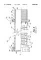
- FIG. 1is a front view of a left ventricular assist system of the present invention connected to a heart of a patient (shown in phantom);
- FIG. 2is a partial cross-sectional view of a left ventricular assist device connected to inflow and outflow conduits of the present invention
- FIG. 3is a partial sectional view of an inflow conduit of the prior art
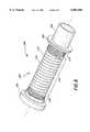
- FIG. 4is a perspective view of an inflow conduit of the present invention.
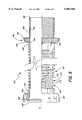
- FIG. 5is a partial sectional view of the inflow conduit of FIG. 4;
- FIG. 6is a perspective view of a further embodiment of an inflow conduit of the present invention.
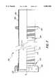
- FIG. 7is a partial sectional view of the inflow conduit of FIG. 6.
- a living human host patient 10is shown in fragmentary front elevational view, and with parts of the patient's anatomy shown in phantom or removed solely for better illustration of the salient features of the present invention. It will be understood that the human host patient 10 preferably has a complete anatomy, and that the use of the present invention does not generally require that any part of the patient's normal anatomy be removed, as might be suggested by FIG. 1.
- a ventricular assist deviceSurgically implanted into the patient's abdominal cavity 12 is the pumping portion 14 of a ventricular assist device, generally referenced with the numeral 16.
- the ventricular assist device 16includes a valved inflow conduit 18 communicating blood from the patient's left ventricle into the pumping portion 14, and a valved outflow conduit 20 communicating blood from the pumping portion 14 to the patient's ascending thoracic aorta.
- the conduits 18, 20typically comprise short valved segments 22, 24 proximate the pumping portion 14 of the device connected in series to elongated flexible segments 26, 28 extending to the heart and ascending aorta, respectively.
- these conduitsare attached to the natural tissues by sutures so that blood flow communication is established and maintained.
- a power cable 30extends outwardly of the patient's body via an incision 32 to a compact controller 34.
- a power sourcesuch as a battery pack worn on a belt about the patient's waist, and generally referenced with the numeral 36, is connected with the controller 34.
- Other means for powering the LVAD 16are known which do not require a cable through the skin, and the present invention is not so limited.
- the pumping portion 14includes a housing 38 within which is received a flexible unitary liner or bag member 40.
- This bag member 40defines a singular blood-contacting inner surface, bounding a variable-volume chamber 42.
- the bag member 40includes a diaphragm portion (not shown) which is reciprocally movable in response to reciprocating movements of a power member (not shown) of the pumping portion 14 to expand and contract the variable-volume chamber 42.
- the bag member 40also defines tubular leg portions 44, 46, extending to and through respective inlet and outlet fittings 48, 50 of the housing 38.
- the housing 38includes structural provisions allowing connection and disconnection of the respective inflow and outflow conduits 18, 20, as will be further described.
- the inner blood-contacting surfaces of the valved conduit segments 22 and 24each also defines a respective reentrant end portion which sealingly contact the reentrant portions of the bag member 40. These sealingly contacting reentrant portions cooperatively define sealing lines 54. Consequently, the flowing blood in moving from the inflow valved conduit segment 22 to the bag 40, and from this bag to the outflow valved conduit segment 24, crosses only two material-surface transitions.
- the first of these material-surface transitionsis from the surface of the inner wall member 52 at the inflow conduit segment 22 to the inner surface of the bag 40
- the second of these material-surface transitionsis from the inner surface of the bag 40 to the inner wall member 53 at the outflow conduit segment 24.
- valved segments 22, 24 of the inflow and outflow conduits 18, 20both contain one way valves 56, 58 respectively.
- the valves 56, 58comprise excised xenograft valves from, for example, pigs.
- tissue valvespreferably have a length-to-diameter aspect ratio greater than natural valves which improves flow therethrough. Again, this preferred arrangement is described in detail in U.S. Pat. No. 5,810,708.
- the present inflow conduit 18is described as a flexible conduit segment connected to a short valved conduit segment, it will be appreciated by those of skill in the art that the inventive aspects disclosed herein could be applied to a combined single segment flexible valved conduit. Indeed, the one-way valves 56, 58 require a smooth inner conduit wall surface for proper attachment and operation, which, as will be described, is provided by the novel flexible segment 26 of the present invention.
- FIG. 2illustrates the connection between the valved segments 22, 24 and the elongate flexible segments 26, 28 of the inflow and outflow conduits. More particularly, each of the flexible segments 26, 28 carries a coupler fitting 60, 62 thereon having internal threads for mating with external threads 64, 66 provided on the respective valved segments 22, 24.
- the fittings 60, 62are captured on and rotate relative to tubular rigid bodies 68, 70, each of which includes outwardly extending flanges 72, 74.
- the coupler fittings 60, 62include inwardly directed radial walls 76, 78 which interfere with the flanges 72, 74. With this arrangement, the flexible segments 26, 28 secure to the valved segments 22, 24 by threading the coupler fittings 60, 62 over the external threads 64, 66.
- the preferred ventricular assist device 16 of the present inventionprovides a minimum of blood contacting surfaces throughout the inflow conduit 18, pumping portion 14, and outflow conduit 20.
- a single sealing line 80, 82is defined between the innermost linings of the juxtaposed segments.
- the flexible segment 26 of the inflow conduit 18includes an inner lining 84 which is wrapped around the end of the rigid body 68 closest to the valved segment 22, as indicated at 86.
- the inner wall member 52 of the valved segment 22is wrapped around the facing end in a like manner, as seen at 87, so that the two blood contacting surfaces meet at the sealing line 80.
- a similar arrangementis provided between an inner lining 88 of the flexible segment 28, and the inner wall member 52 of the valved segment 24, resulting in the blood sealing line 82.
- the flexible segment 100 on one endincludes a rigid ring-shaped body 102 surrounded by coupler fitting 104.
- a wave washer 106is disposed between an inwardly extending radial wall 108 of the fitting 104, and the flange 110 of the rigid body 102.
- the wave washer 106produces a relatively constant compressing force at the blood sealing line formed between the flexible segment 100 and associated valved conduit segment (not shown).
- the rigid body 102is integral formed with a reinforcement cage 112 that extends the length of the flexible portion of the conduit segment 100 and terminates in a rigid band 114.
- the reinforcement cage 112includes a plurality of circumferentially formed ribs 116 joined at periodic locations by bridges 118. Although not shown well in FIG. 3, the bridges 118 are circumferentially offset from each other from rib-to-rib to enable the reinforcement cage 112 to be axially extended (this is better seen in the conduit segment of the present invention seen in perspective in FIG. 4).
- the cage 112is desirably formed of a resilient biocompatible material such as polypropylene, and axial elongation of the segment 100 is permitted by virtue of the ribs 116 bending to enlarge the axial spaces 120 therebetween.
- the term "rigid” referring to the body 102 and band 114is defined relative to the flexibility of the intermediate ribs 116, and those of skill in the art will recognize that polypropylene has inherent resiliency and is not "rigid” in the abstract.
- the body 102 and band 114are desirably as rigid as needed to facilitate structural connection of the cage 112 to the respective ends of the segment 100.
- the body 102 and band 114also provide a "handle" of sorts to assist the surgeon in attaching the segment 100 between the heart and associated short valved conduit.
- the reinforcement cage 112helps prevent gross distortion or collapse of a convoluted tubular graft body 122 extending therethrough. Nevertheless, extension of the flexible segment 100 during implantation of an associated ventricular assist device may cause excessive spaces to be formed between the ribs of the reinforcement cage 112. In such cases, there is the potential for the surgeon to contact the tubular graft body 122 within the reinforcement cage 112 with a finger or other instrument, resulting in damage or collapse.
- the convoluted tubular graft body 122extends from a first end 124 to a second end 126.
- the first end 124is wrapped tightly around the rigid body 102, as previously described, the convolutions being smoothed at that end by a thermo-forming process.
- Stitching 128surrounds the first end 124 and attaches the graft body 122 to the rigid body 102.
- the second end 126extends through a rigid, tubular cannula body 130 and terminates at a distal rim 132 thereof.
- a smooth piece of fabric 134surrounds the tubular cannula body 130 and is attached at the distal rim 132 to the second end 126 using a stitch line 136.
- the fabric 132terminates at an apical sewing ring 140.
- the sewing ring 140includes an inner sponge-like member 142 an outer fabric covering 144.
- the fabric 134attaches to the outer fabric cover 144 of the sewing ring at a stitch line 146.
- the outer fabric covered 144 of the sewing ringis secured to the tubular graft body 122 via plurality of periodic discrete stitches 152, as seen in the lower portion of FIG. 3.
- the tubular cannula body 130is sized to extend within an excised opening at the apex of the left ventricle.
- the end of the flexible segment 100 having the tubular cannula body 130is considered the "upstream” end, and the opposite end having the coupler fitting 104 is the "downstream" end.
- flow patterns in the inflow conduit side of a ventricular assist deviceare highly variable, and may even induce negative pressures.
- the convoluted tubular graft body 122 of the prior art, as seen in FIG. 3,is advantageous for its high flexibility and capacity for elongation.
- the convoluted tubular graft body 122has a relatively high resistance to kinking upon bending.
- negative pressures generated within the flexible segment of inflow conduit 100may cause unwarranted narrowing or inward distortion of the tubular graft body 122.
- the convolutionsmay induce undesirable eddy currents near the wall of the tubular graft body and the inner concave portions of the convolutions may provide blood stagnation sites, further encouraging undesirable thrombotic depositions.
- the convolutions of the tubular graft body 122are unsuitable for wrapping around the cannula body 130, as the exterior surface thereof must pass cleanly through and seal against the excised opening at the apex of the left ventricle. Therefore, the separate piece of fabric 134 having a smooth construction is needed. This increases the time and expense of assembly of the flexible segment 100.
- FIGS. 4 and 5illustrate an improved flexible segment 160 for an inflow conduit 18 (FIG. 1) of a ventricular assist device 16.
- the flexible segment 160shares certain features with the flexible segment 100 of the prior art shown in FIG. 3.
- the flexible segment 168includes a coupler fitting 162, reinforcement cage 164, a sewing ring 166, and a tubular cannula body 186 (FIG. 5).
- the cannula body 186is covered by a portion of an improved tubular graft body 168 as will be described.
- the flexible segment 28preferably includes a convoluted tubular graft body of woven polyethylene terephthalate fabric protected by an outer reinforcement cage (much like the prior art inflow conduit of FIG. 3).
- the fabricmay be impregnated with a natural sealant, such as bovine collagen or bovine gelatin.
- FIG. 5illustrates the improved tubular graft body 168 for the inflow conduit 18 (FIG. 1) extending through and defining the inner lumen of the flexible segment 160.
- the tubular graft body 168includes an internally smooth, non-crimped flexible wall 170 and a plurality of axially spaced support members 172 around the exterior of the wall.
- the support members 172comprise individual coils of a single helically wound support member 174.
- the support member 174extends axially within the reinforcement cage 164 between a rigid body portion 176 and a rigid band 178, while the flexible wall 170 continues axially outward to both ends of the tubular graft body 168 as will be described.
- tubular wall 170comprises a knitted fabric sealed by a bovine collagen or bovine gelatin. Knitted fabrics for such uses typically have larger pore sizes and are significantly more flexible than woven fabrics. The large pore sizes necessitate the use of a sealant. Because of the flexibility of the knitted structure, however, the tubular wall 170 may be bent a substantial degree, more so than woven tubes, without undesirable kinking. Moreover, elimination of the convolutions in tubular graft bodies of the prior art reduces the potential for thrombosis and hemolysis. That is, the smooth inner surface of the tubular wall 170 facilitates washing of the tubular wall under conditions of transient or low blood flow.
- the external support member 174may be formed in a variety of configurations, including the helically wound circular cross-section as shown. Various other reinforcing techniques for tubular grafts are known in the art, including, but not limited to discrete bands, adhered ribs, wound tape, and the like.
- the support member 174comprises a helical polymer coil, preferably polypropylene, thermally bonded to the exterior surface of tubular wall 170.
- Other biocompatible materials capable of being thermally bonded or otherwise adhered to the exterior surface of tubular wall 170may be used for the support member 174, including PTFE.
- the support member 174prevents the tubular wall 170 from collapsing inward, yet without significantly affecting the flexibility thereof.
- the external support member 174 surrounding the tubular wall 170helps protect the tubular graft body 168 from damage from inadvertent contact upon extension of the flexible segment 160. That is, during implantation of an associated ventricular assist device excessive spaces may be formed between the ribs of the reinforcement cage 164 from elongation of the flexible segment 160. In such cases, the surgeon might inadvertently contact the tubular graft body 168 within the reinforcement cage 164 with a finger or other instrument. The support member 174 protects the tubular wall 170 from collapse or damage.
- a particularly preferred tubular graft body 168 including a sealed, smooth tubular wall 170 having a bore diameter of about 22 mm and a helically wound external support member 174,may be obtained on special order from Vascutek of Inchinnan, Scotland, under the trade name GELSEAL ERT®.
- the tubular graft body 168extends around the downstream end of the rigid body member 176 and is sewn thereto with a line of stitches 180.
- This constructionpresents a coupling surface 182 as seen in FIG. 4 which is designed to mate with a complementary coupling surface of a valved conduit segment.
- the tubular wall 170thus forms the "lining 84" as previously denoted with respect to FIG. 2.
- a wave washer 184(FIG. 5) creates a relatively constant compressive force between the mating coupling surfaces.
- the tubular wall 170wraps around a distal rim 188 of the tubular cannula body 186 and continues into proximity with the sewing ring 166.
- the sewing ringincludes an inner sponge-like portion 190 surrounded by a fabric covering 192.
- the fabric covering 192is sewn to the tubular graft body 168 using, for example, stitches 194.
- the sewing ring 166attaches to the reinforcement cage 164 using stitches 196.
- the use of a smooth-walled tubular graft body 168eliminates the need for a separate piece of fabric surrounding the cannula body 186, such as the prior art fabric piece 134 seen in FIG. 3.
- FIGS. 6 and 7illustrates a second embodiment of a smooth-walled, non-crimped flexible segment 200 for an inflow conduit of a ventricular assist device.
- the flexible segment 200has a downstream end with a coupler fitting 202 and an upstream end with a sewing ring 204 and a tubular cannula body 206.
- a tubular graft body 208comprises a flexible tubular wall 210 and a plurality of external reinforcing members 212.
- the material and construction of the tubular graft body 208is sufficiently flexible while at the same time being sufficiently able to withstand collapse, so as to obviate the need for the reinforcement cage.
- tubular graft body 208is formed of a closed structure polytetrafluoroethylene (PTFE).
- PTFEpolytetrafluoroethylene
- a smooth PTFE graft body 208 without convolutionsis particularly useful in the context of the inflow conduit for a ventricular assist device because it reduces the tendency to induce irregular flow patterns.
- "Smooth" in the context of the improved inflow conduit segment 200means that the inner lumen of the graft body 208 is at least free of convolutions, though it will be noted that the surface smoothness of a PTFE graft body is dependent on the smoothness of the extrusion forming mandrel. Indeed, the mandrel is desirably highly polished resulting in an extremely smooth inner lumen of the tubular graft body 208.
- closed structured PTFEsignificantly reduces tissue ingrowth from the exterior or ends of the tubular graft body 208 which otherwise might eventually encroach on the inner lumen and initiate a thrombotic response.
- the external reinforcing members 212 of the flexible segment 200 in FIGS. 6 and 7obviate the need for a reinforcement cage, such as the cage 164 of FIG. 5, which reduces the difficulty associated with explant surgery of the LVAD. More particularly, host tissue tends to encapsulate the reinforcement cage 164 of the segment 160 of FIG. 5 after a period of implantation. When the LVAD is to be removed from the patient, the surrounding tissue ingrowth must be carefully cut away, which is complicated by the intricate nature of the reinforcement cage 164.
- the PTFE tubular graft body 208 of the flexible segment 200 in FIGS. 6 and 7has no surrounding protective cage, and is thus much easier to remove from the patient once the need for the LVAD ceases.
- the external reinforcement members 212may comprise a series of coils of a continuous rib having a circular or semi-circular cross-section projecting outward from the tubular wall 210.
- the reinforcement coils 212extend generally between the coupler fitting 202 and sewing ring 204 and are preferably axially spaced apart in a mid-region 214 while being more tightly spaced (even in contact) at upstream and downstream regions 216, 218, respectively.
- the loosely spaced mid-region 214permits the segment 200 to bend, and the tightly spaced regions 216, 218, provide rigidity to the flexible segment 200 in the areas adjacent the associated coupling structures (i.e., the fitting 202 and the sewing ring 204). This helps the surgeon in connecting the flexible segment 200 in its proper place, and takes the place of the rigid bands formed on either end of the reinforcement cage in the first embodiment of FIGS. 4 and 5.
- the flexible conduit segment 200additionally includes a rigid body portion 220 on the downstream end of the tubular graft body 208.
- This rigid body portion 220provides an interface with the coupler fitting 202, and also provides a terminal lip 222 around which is wrapped the downstream end of the tubular wall 210 to form a surface for contacting a like surface on the associated valved conduit, thus minimizing the number of blood contacting surfaces across the transition.
- the tubular wall 210thus forms the "lining 84" as previously denoted with respect to FIG. 2.
- the tubular wall 210wraps around the tubular cannula body 206 at outer section 224 and attaches to the sewing ring 204. Again, this eliminates the need for a separate piece of fabric or other such covering around cannula body 206.
- the PTFE tubular wall 210 and external reinforcement members 212may be formed by various means well-known in the art, such as, for example, extrusion followed by expansion.
- the tubular wall 210comprises an extruded PTFE base tube with a thin external tape wrapped around it and laminated thereto for hoop strength.
- the reinforcement members 212preferably comprise a bead helically wrapped around the tubular wall 210 and also laminated thereto.
- the tubular wall 210has a thickness of about 0.7 mm.
- the reinforcing coils 212may be circular in cross section having a diameter of about 1.6 mm, and extend radially outward from the tubular wall 210 a distance of approximately 1.6 mm (i.e., a circular bead on the exterior of the tubular wall 210).
- the coils 212have a flat or groove on the side in contact with the tubular wall 210 to reduce the undercuts formed on the longitudinal edges of a wholly circular bead.
- the base tube of the tubular wall 210desirably has a pore size of less than 20 ⁇ m, and preferably less than about 15 ⁇ m, potentially down to about 2 ⁇ m.
- the water entry pressure for the base tubeis at least about 5 psi.
- a thin PTFE tape wrapped about and laminated to the base tubepreferably has a thickness of about 0.01 mm and an ethanol bubble point of at least about 2 psi, further exhibiting no measurable nodal formations. The result is an extremely low porosity tubular wall 210 that resists tissue ingrowth therethrough and also resists endothelial cell formation therealong that may otherwise tend to migrate into the flow passage from the ends of the conduit 200.
- a sealed fabric graftmay be adequately supported by external beading so as to eliminate the need for a reinforcement cage.
- this hybrid conduit segmentmay include a tubular wall (such as wall 170 in FIG. 5) of a knitted fabric sealed by bovine gelatin and supported by a coil (such as external reinforcing members 212 of FIG. 7) of sufficient rigidity to adequately prevent inward collapse of the conduit segment from negative lumen pressures.
- the coilwould be more tightly wound at the ends than in the middle so as to facilitate handling by the surgeon yet not impede overall flexibility of the conduit to any great extent.
- fabric and coilare contemplated, including a preferred combination of a PTFE coil bonded to a polyethylene terephthalate fabric tube.
- support structure other than a coilmay be used, such as tape, rings, or other similar expedients.
Landscapes
- Health & Medical Sciences (AREA)
- Engineering & Computer Science (AREA)
- Heart & Thoracic Surgery (AREA)
- Cardiology (AREA)
- Biomedical Technology (AREA)
- General Health & Medical Sciences (AREA)
- Veterinary Medicine (AREA)
- Public Health (AREA)
- Life Sciences & Earth Sciences (AREA)
- Animal Behavior & Ethology (AREA)
- Anesthesiology (AREA)
- Hematology (AREA)
- Mechanical Engineering (AREA)
- Oral & Maxillofacial Surgery (AREA)
- Transplantation (AREA)
- Vascular Medicine (AREA)
- Prostheses (AREA)
- External Artificial Organs (AREA)
- Physical Deposition Of Substances That Are Components Of Semiconductor Devices (AREA)
- Feeding Of Articles To Conveyors (AREA)
Abstract
Description
Claims (37)
Priority Applications (7)
| Application Number | Priority Date | Filing Date | Title |
|---|---|---|---|
| US09/191,506US6001056A (en) | 1998-11-13 | 1998-11-13 | Smooth ventricular assist device conduit |
| CA002391234ACA2391234C (en) | 1998-11-13 | 1999-11-09 | Smooth ventricular assist device conduit |
| AU27060/00AAU2706000A (en) | 1998-11-13 | 1999-11-09 | Smooth ventricular assist device conduit |
| DE69938145TDE69938145T2 (en) | 1998-11-13 | 1999-11-09 | SMOOTH VESSEL FOR CHAMBER SUPPORT DEVICE |
| AT99968849TATE385752T1 (en) | 1998-11-13 | 1999-11-09 | SMOOTH VESSEL FOR CHAMBER SUPPORT DEVICE |
| PCT/US1999/026427WO2000028924A2 (en) | 1998-11-13 | 1999-11-09 | Smooth ventricular assist device conduit |
| EP99968849AEP1128786B1 (en) | 1998-11-13 | 1999-11-09 | Smooth ventricular assist device conduit |
Applications Claiming Priority (1)
| Application Number | Priority Date | Filing Date | Title |
|---|---|---|---|
| US09/191,506US6001056A (en) | 1998-11-13 | 1998-11-13 | Smooth ventricular assist device conduit |
Publications (1)
| Publication Number | Publication Date |
|---|---|
| US6001056Atrue US6001056A (en) | 1999-12-14 |
Family
ID=22705758
Family Applications (1)
| Application Number | Title | Priority Date | Filing Date |
|---|---|---|---|
| US09/191,506Expired - LifetimeUS6001056A (en) | 1998-11-13 | 1998-11-13 | Smooth ventricular assist device conduit |
Country Status (7)
| Country | Link |
|---|---|
| US (1) | US6001056A (en) |
| EP (1) | EP1128786B1 (en) |
| AT (1) | ATE385752T1 (en) |
| AU (1) | AU2706000A (en) |
| CA (1) | CA2391234C (en) |
| DE (1) | DE69938145T2 (en) |
| WO (1) | WO2000028924A2 (en) |
Cited By (108)
| Publication number | Priority date | Publication date | Assignee | Title |
|---|---|---|---|---|
| US6146325A (en)* | 1999-06-03 | 2000-11-14 | Arrow International, Inc. | Ventricular assist device |
| WO2002098488A2 (en) | 2001-06-05 | 2002-12-12 | Edwards Lifesciences Corporation | Non-porous smooth ventricular assist device conduit |
| WO2002100454A1 (en)* | 2001-06-11 | 2002-12-19 | Boston Scientific Limited | COMPOSITE ePTFE/TEXTILE PROSTHESIS |
| US20030023131A1 (en)* | 2001-06-06 | 2003-01-30 | Antaki James F. | Apparatus and method for reducing heart pump backflow |
| US20030023255A1 (en)* | 2001-06-29 | 2003-01-30 | Miles Scott D. | Cannulation apparatus and method |
| US20030050528A1 (en)* | 2001-09-11 | 2003-03-13 | Shannon Donald T. | Method for substantially non-delaminable smooth ventricular assist device conduit and product from same |
| US6569079B2 (en)* | 2000-04-28 | 2003-05-27 | Ministero Dell'universita E Della Ricerca Scientifica E Tecnologica | Ventricular assist device, accessory therefore and method of use |
| US20030130668A1 (en)* | 2001-06-29 | 2003-07-10 | Nieman Timothy R. | Endoscopic cannulation apparatus and method |
| US20030233144A1 (en)* | 2002-06-13 | 2003-12-18 | Antaki James F. | Low profile inlet for an implantable blood pump |
| US20040002624A1 (en)* | 2002-06-26 | 2004-01-01 | Yu Long Sheng | Ventricular connector |
| US20040182511A1 (en)* | 2001-06-11 | 2004-09-23 | Scimed Life Systems, Inc. | Pressure lamination method for forming composite ePTFE/textile and ePTFE/stent/textile prostheses |
| EP1462133A2 (en) | 2003-03-28 | 2004-09-29 | Terumo Corporation | Method and apparatus for adjusting a length of the inflow conduit on a ventricular assist device |
| WO2004082742A1 (en) | 2003-03-21 | 2004-09-30 | Ventracor Limited | Improved cannula |
| US6802806B2 (en) | 2002-09-23 | 2004-10-12 | Cleveland Clinic Foundation | Apparatus for use with an inflow cannula of ventricular assist device |
| US20040242954A1 (en)* | 2003-05-30 | 2004-12-02 | Moises Calderon | Universal pneumatic ventricular assist device |
| WO2004052172A3 (en)* | 2002-12-06 | 2005-02-10 | World Heart Corp | Miniature, pulsatile implantable ventricular assist devices and methods of controlling ventricular assist devices |
| US6936072B2 (en) | 1999-08-18 | 2005-08-30 | Intrinsic Therapeutics, Inc. | Encapsulated intervertebral disc prosthesis and methods of manufacture |
| US6942672B2 (en) | 2001-10-23 | 2005-09-13 | Vascor, Inc. | Method and apparatus for attaching a conduit to the heart or a blood vessel |
| US20060004346A1 (en)* | 2004-06-17 | 2006-01-05 | Begg John D | Bend relief |
| US20060074271A1 (en)* | 2004-07-22 | 2006-04-06 | Cotter Christopher J | Heart pump connector |
| US7077801B2 (en) | 2003-02-19 | 2006-07-18 | Corlife Gbr | Methods and devices for improving cardiac output |
| US7172550B2 (en) | 2003-07-31 | 2007-02-06 | Terumo Corporation | Adjustable coupling mechanism for the conduit on a ventricular assist device |
| US20070055357A1 (en)* | 2005-09-02 | 2007-03-08 | Pokorney James L | Prosthetic heart valve housing |
| US20070112422A1 (en)* | 2005-11-16 | 2007-05-17 | Mark Dehdashtian | Transapical heart valve delivery system and method |
| US20070197854A1 (en)* | 2006-01-27 | 2007-08-23 | Circulite, Inc. | Heart assist system |
| WO2008017036A1 (en)* | 2006-08-02 | 2008-02-07 | Gordon Cohen | Bifurcated flow device for cardio-pulmonary assist or support and associated methods |
| US20080076959A1 (en)* | 2006-08-30 | 2008-03-27 | Circulite, Inc. | Devices, methods and systems for establishing supplemental blood flow in the circulatory system |
| US20080076960A1 (en)* | 2006-08-30 | 2008-03-27 | Circulite, Inc. | Cannula insertion devices, systems, and methods including a compressible member |
| WO2008113122A1 (en)* | 2007-03-20 | 2008-09-25 | Ventrassist Pty Ltd | Heart assist device, cannula and filter therefor |
| US20090023975A1 (en)* | 2007-07-19 | 2009-01-22 | Circulite, Inc. | Cannula for heart chamber implantation and related systems and methods |
| US7500978B2 (en) | 2003-06-20 | 2009-03-10 | Intrinsic Therapeutics, Inc. | Method for delivering and positioning implants in the intervertebral disc environment |
| US20090076482A1 (en)* | 2007-09-14 | 2009-03-19 | Avalon Laboratories, Inc. | Cannula reinforcing band and method |
| US7507243B2 (en) | 1999-08-18 | 2009-03-24 | Gregory Lambrecht | Devices and method for augmenting a vertebral disc |
| US7513911B2 (en) | 1999-08-18 | 2009-04-07 | Intrinsic Therapeutics, Inc. | Method of implanting dynamically stable spinal implant |
| US7524333B2 (en) | 1999-08-18 | 2009-04-28 | Intrinsic Therapeutics, Inc. | Method of anchoring an implant in an intervertebral disc |
| US20090112050A1 (en)* | 2007-10-24 | 2009-04-30 | Circulite, Inc. | Transseptal cannula, tip, delivery system, and method |
| US7553329B2 (en) | 1999-08-18 | 2009-06-30 | Intrinsic Therapeutics, Inc. | Stabilized intervertebral disc barrier |
| US20090171137A1 (en)* | 2006-09-14 | 2009-07-02 | Circulite, Inc. | Intravascular blood pump and catheter |
| US20090182188A1 (en)* | 2006-08-30 | 2009-07-16 | Circulite, Inc. | Devices, methods and systems for establishing supplemental blood flow in the circulatory system |
| US20100036401A1 (en)* | 2008-07-09 | 2010-02-11 | The Cleveland Clinic Foundation | Vascular graft and method of use |
| US20100087742A1 (en)* | 2008-09-30 | 2010-04-08 | Ihc Intellectual Asset Management, Llc | Physiological characteristic determination for a medical device user |
| US7717961B2 (en) | 1999-08-18 | 2010-05-18 | Intrinsic Therapeutics, Inc. | Apparatus delivery in an intervertebral disc |
| US7727241B2 (en) | 2003-06-20 | 2010-06-01 | Intrinsic Therapeutics, Inc. | Device for delivering an implant through an annular defect in an intervertebral disc |
| US20100249491A1 (en)* | 2009-03-27 | 2010-09-30 | Circulite, Inc. | Two-piece transseptal cannula, delivery system, and method of delivery |
| US20100249490A1 (en)* | 2009-03-27 | 2010-09-30 | Circulite, Inc. | Transseptal cannula device, coaxial balloon delivery device, and methods of using the same |
| US20110112353A1 (en)* | 2009-11-09 | 2011-05-12 | Circulite, Inc. | Bifurcated outflow cannulae |
| US20110118833A1 (en)* | 2009-11-15 | 2011-05-19 | Thoratec Corporation | Attachment device and method |
| US7959679B2 (en) | 1999-08-18 | 2011-06-14 | Intrinsic Therapeutics, Inc. | Intervertebral anulus and nucleus augmentation |
| US20110160850A1 (en)* | 2009-12-30 | 2011-06-30 | Thoratec Corporation | Blood Pump System With Mounting Cuff |
| US7972337B2 (en) | 2005-12-28 | 2011-07-05 | Intrinsic Therapeutics, Inc. | Devices and methods for bone anchoring |
| US7976271B2 (en) | 2006-01-13 | 2011-07-12 | Heartware, Inc. | Stabilizing drive for contactless rotary blood pump impeller |
| US20110275882A1 (en)* | 2010-05-05 | 2011-11-10 | Syncardia Systems, Inc | Valve for ventricular assist device |
| US8231678B2 (en) | 1999-08-18 | 2012-07-31 | Intrinsic Therapeutics, Inc. | Method of treating a herniated disc |
| US8323341B2 (en) | 2007-09-07 | 2012-12-04 | Intrinsic Therapeutics, Inc. | Impaction grafting for vertebral fusion |
| US20130096364A1 (en)* | 2011-10-13 | 2013-04-18 | Steven H. Reichenbach | Pump and method for mixed flow blood pumping |
| US8454612B2 (en) | 2007-09-07 | 2013-06-04 | Intrinsic Therapeutics, Inc. | Method for vertebral endplate reconstruction |
| US8672611B2 (en) | 2006-01-13 | 2014-03-18 | Heartware, Inc. | Stabilizing drive for contactless rotary blood pump impeller |
| CN103767743A (en)* | 2014-01-23 | 2014-05-07 | 苏州同心医疗器械有限公司 | Auxiliary tool for assisting installation of implant of heart chamber |
| US8728012B2 (en) | 2008-12-19 | 2014-05-20 | St. Jude Medical, Inc. | Apparatus and method for measuring blood vessels |
| US8771164B2 (en) | 2008-03-28 | 2014-07-08 | Vitalmex Internacional S.A. De C.V. | Fluid pumping ventricular assist device and components with static seal |
| US20140316426A1 (en)* | 2011-05-16 | 2014-10-23 | Berlin Heart Gmbh | Connection system for the detachable fixation of a hollow cylindrical component at a recess |
| US8882744B2 (en) | 2012-02-27 | 2014-11-11 | Thoratec Corporation | Quick-connect outflow tube for ventricular assist device |
| US8905961B2 (en) | 2008-12-19 | 2014-12-09 | St. Jude Medical, Inc. | Systems, apparatuses, and methods for cardiovascular conduits and connectors |
| WO2014169023A3 (en)* | 2013-04-09 | 2014-12-31 | Circulite, Inc. | Blood flow system with operator attachable components |
| US9138228B2 (en) | 2004-08-11 | 2015-09-22 | Emory University | Vascular conduit device and system for implanting |
| US9144637B2 (en) | 2011-03-02 | 2015-09-29 | Thoratec Corporation | Ventricular cuff |
| US9199019B2 (en) | 2012-08-31 | 2015-12-01 | Thoratec Corporation | Ventricular cuff |
| US9308015B2 (en) | 2007-04-24 | 2016-04-12 | Emory University | Conduit device and system for implanting a conduit device in a tissue wall |
| US9320875B2 (en) | 2011-02-01 | 2016-04-26 | Emory University | Systems for implanting and using a conduit within a tissue wall |
| US9381082B2 (en) | 2011-04-22 | 2016-07-05 | Edwards Lifesciences Corporation | Devices, systems and methods for accurate positioning of a prosthetic valve |
| EP3056231A1 (en)* | 2010-10-13 | 2016-08-17 | Thoratec Corporation | Blood pump |
| US9463268B2 (en) | 2010-09-07 | 2016-10-11 | Paul A. Spence | Cannula systems and methods |
| US9532773B2 (en) | 2011-01-28 | 2017-01-03 | Apica Cardiovascular Limited | Systems for sealing a tissue wall puncture |
| US9566146B2 (en) | 2008-12-19 | 2017-02-14 | St. Jude Medical, Inc. | Cardiovascular valve and valve housing apparatuses and systems |
| US9585991B2 (en) | 2012-10-16 | 2017-03-07 | Heartware, Inc. | Devices, systems, and methods for facilitating flow from the heart to a blood pump |
| US9687345B2 (en) | 2014-05-29 | 2017-06-27 | Edwards Lifesciences Cardiaq Llc | Prosthesis, delivery device and methods of use |
| US9808283B2 (en) | 2013-12-04 | 2017-11-07 | Heartware, Inc. | Apparatus and methods for cutting an atrial wall |
| US9981076B2 (en) | 2012-03-02 | 2018-05-29 | Tc1 Llc | Ventricular cuff |
| US10028741B2 (en) | 2013-01-25 | 2018-07-24 | Apica Cardiovascular Limited | Systems and methods for percutaneous access, stabilization and closure of organs |
| US20180318480A1 (en)* | 2016-03-30 | 2018-11-08 | Heartware, Inc. | Flanged heart tissue blocker |
| US10149757B2 (en) | 2013-03-15 | 2018-12-11 | Edwards Lifesciences Corporation | System and method for transaortic delivery of a prosthetic heart valve |
| WO2019108515A1 (en)* | 2017-11-29 | 2019-06-06 | Richard Wampler | Apparatus, methods and systems for dynamic ventricular assistance |
| JP2019528849A (en)* | 2016-09-01 | 2019-10-17 | アビオメド オイローパ ゲーエムベーハー | Blood pump with flow cannula |
| US10485909B2 (en) | 2014-10-31 | 2019-11-26 | Thoratec Corporation | Apical connectors and instruments for use in a heart wall |
| EP2964303B1 (en)* | 2013-03-07 | 2019-11-27 | CircuLite, Inc. | Malleable cannula |
| US10518012B2 (en) | 2013-03-15 | 2019-12-31 | Apk Advanced Medical Technologies, Inc. | Devices, systems, and methods for implanting and using a connector in a tissue wall |
| JP2020065830A (en)* | 2018-10-26 | 2020-04-30 | 株式会社サンメディカル技術研究所 | Medical tube protector |
| US10660998B2 (en) | 2016-08-12 | 2020-05-26 | Tci Llc | Devices and methods for monitoring bearing and seal performance |
| US10724534B2 (en) | 2014-11-26 | 2020-07-28 | Tc1 Llc | Pump and method for mixed flow blood pumping |
| US10857273B2 (en) | 2016-07-21 | 2020-12-08 | Tc1 Llc | Rotary seal for cantilevered rotor pump and methods for axial flow blood pumping |
| US10894116B2 (en) | 2016-08-22 | 2021-01-19 | Tc1 Llc | Heart pump cuff |
| US10918826B2 (en) | 2007-06-26 | 2021-02-16 | Nordson Corporation | Coaxial venal cannula |
| US11235137B2 (en) | 2017-02-24 | 2022-02-01 | Tc1 Llc | Minimally invasive methods and devices for ventricular assist device implantation |
| US20220161022A1 (en)* | 2019-04-05 | 2022-05-26 | Scandinavian Real Heart Ab | A vascular coupling device |
| US11368081B2 (en) | 2018-01-24 | 2022-06-21 | Kardion Gmbh | Magnetic coupling element with a magnetic bearing function |
| US11754075B2 (en) | 2018-07-10 | 2023-09-12 | Kardion Gmbh | Impeller for an implantable, vascular support system |
| US11944805B2 (en) | 2020-01-31 | 2024-04-02 | Kardion Gmbh | Pump for delivering a fluid and method of manufacturing a pump |
| US12005248B2 (en) | 2018-05-16 | 2024-06-11 | Kardion Gmbh | Rotor bearing system |
| US12064615B2 (en) | 2018-05-30 | 2024-08-20 | Kardion Gmbh | Axial-flow pump for a ventricular assist device and method for producing an axial-flow pump for a ventricular assist device |
| US12076549B2 (en) | 2018-07-20 | 2024-09-03 | Kardion Gmbh | Feed line for a pump unit of a cardiac assistance system, cardiac assistance system and method for producing a feed line for a pump unit of a cardiac assistance system |
| US12107474B2 (en) | 2018-05-16 | 2024-10-01 | Kardion Gmbh | End-face rotating joint for transmitting torques |
| US12144976B2 (en) | 2018-06-21 | 2024-11-19 | Kardion Gmbh | Method and device for detecting a wear condition of a ventricular assist device and for operating same, and ventricular assist device |
| US12194287B2 (en) | 2018-05-30 | 2025-01-14 | Kardion Gmbh | Method of manufacturing electrical conductor tracks in a region of an intravascular blood pump |
| US12201823B2 (en) | 2018-05-30 | 2025-01-21 | Kardion Gmbh | Line device for conducting a blood flow for a heart support system, heart support system, and method for producing a line device |
| WO2025034732A1 (en)* | 2023-08-07 | 2025-02-13 | Edwards Lifesciences Corporation | Prosthetic heart valves |
| US12263333B2 (en) | 2018-06-21 | 2025-04-01 | Kardion Gmbh | Stator vane device for guiding the flow of a fluid flowing out of an outlet opening of a ventricular assist device, ventricular assist device with stator vane device, method for operating a stator vane device and manufacturing method |
| US12383727B2 (en) | 2018-05-30 | 2025-08-12 | Kardion Gmbh | Motor housing module for a heart support system, and heart support system and method for mounting a heart support system |
| US12390633B2 (en) | 2018-08-07 | 2025-08-19 | Kardion Gmbh | Bearing device for a heart support system, and method for rinsing a space in a bearing device for a heart support system |
Families Citing this family (30)
| Publication number | Priority date | Publication date | Assignee | Title |
|---|---|---|---|---|
| US6254564B1 (en) | 1998-09-10 | 2001-07-03 | Percardia, Inc. | Left ventricular conduit with blood vessel graft |
| US6517571B1 (en)† | 1999-01-22 | 2003-02-11 | Gore Enterprise Holdings, Inc. | Vascular graft with improved flow surfaces |
| DE102005003632A1 (en) | 2005-01-20 | 2006-08-17 | Fraunhofer-Gesellschaft zur Förderung der angewandten Forschung e.V. | Catheter for the transvascular implantation of heart valve prostheses |
| US7896915B2 (en) | 2007-04-13 | 2011-03-01 | Jenavalve Technology, Inc. | Medical device for treating a heart valve insufficiency |
| BR112012021347A2 (en) | 2008-02-26 | 2019-09-24 | Jenavalve Tecnology Inc | stent for positioning and anchoring a valve prosthesis at an implantation site in a patient's heart |
| US9044318B2 (en) | 2008-02-26 | 2015-06-02 | Jenavalve Technology Gmbh | Stent for the positioning and anchoring of a valvular prosthesis |
| US8579964B2 (en) | 2010-05-05 | 2013-11-12 | Neovasc Inc. | Transcatheter mitral valve prosthesis |
| US10856978B2 (en) | 2010-05-20 | 2020-12-08 | Jenavalve Technology, Inc. | Catheter system |
| WO2011147849A1 (en) | 2010-05-25 | 2011-12-01 | Jenavalve Technology Inc. | Prosthetic heart valve and transcatheter delivered endoprosthesis comprising a prosthetic heart valve and a stent |
| US9554897B2 (en) | 2011-04-28 | 2017-01-31 | Neovasc Tiara Inc. | Methods and apparatus for engaging a valve prosthesis with tissue |
| US9308087B2 (en) | 2011-04-28 | 2016-04-12 | Neovasc Tiara Inc. | Sequentially deployed transcatheter mitral valve prosthesis |
| US9345573B2 (en) | 2012-05-30 | 2016-05-24 | Neovasc Tiara Inc. | Methods and apparatus for loading a prosthesis onto a delivery system |
| US9572665B2 (en) | 2013-04-04 | 2017-02-21 | Neovasc Tiara Inc. | Methods and apparatus for delivering a prosthetic valve to a beating heart |
| CN105491978A (en) | 2013-08-30 | 2016-04-13 | 耶拿阀门科技股份有限公司 | Radially collapsible frame for a prosthetic valve and method for manufacturing such a frame |
| EP3270825B1 (en) | 2015-03-20 | 2020-04-22 | JenaValve Technology, Inc. | Heart valve prosthesis delivery system |
| US10709555B2 (en) | 2015-05-01 | 2020-07-14 | Jenavalve Technology, Inc. | Device and method with reduced pacemaker rate in heart valve replacement |
| CA3007660A1 (en) | 2015-12-15 | 2017-06-22 | Neovasc Tiara Inc. | Transseptal delivery system |
| US10433952B2 (en) | 2016-01-29 | 2019-10-08 | Neovasc Tiara Inc. | Prosthetic valve for avoiding obstruction of outflow |
| EP3228336A1 (en) | 2016-04-08 | 2017-10-11 | Berlin Heart GmbH | Cannula assembly and blood pump system and their use |
| WO2017195125A1 (en) | 2016-05-13 | 2017-11-16 | Jenavalve Technology, Inc. | Heart valve prosthesis delivery system and method for delivery of heart valve prosthesis with introducer sheath and loading system |
| CA3042588A1 (en) | 2016-11-21 | 2018-05-24 | Neovasc Tiara Inc. | Methods and systems for rapid retraction of a transcatheter heart valve delivery system |
| WO2018138658A1 (en) | 2017-01-27 | 2018-08-02 | Jenavalve Technology, Inc. | Heart valve mimicry |
| CA3073834A1 (en) | 2017-08-25 | 2019-02-28 | Neovasc Tiara Inc. | Sequentially deployed transcatheter mitral valve prosthesis |
| CN113271890B (en) | 2018-11-08 | 2024-08-30 | 内奥瓦斯克迪亚拉公司 | Ventricular deployment of transcatheter mitral valve prosthesis |
| CA3132873A1 (en) | 2019-03-08 | 2020-09-17 | Neovasc Tiara Inc. | Retrievable prosthesis delivery system |
| CA3135753C (en) | 2019-04-01 | 2023-10-24 | Neovasc Tiara Inc. | Controllably deployable prosthetic valve |
| US11491006B2 (en) | 2019-04-10 | 2022-11-08 | Neovasc Tiara Inc. | Prosthetic valve with natural blood flow |
| US11779742B2 (en) | 2019-05-20 | 2023-10-10 | Neovasc Tiara Inc. | Introducer with hemostasis mechanism |
| JP7520897B2 (en) | 2019-06-20 | 2024-07-23 | ニオバスク ティアラ インコーポレイテッド | Thin prosthetic mitral valve |
| WO2024102411A1 (en) | 2022-11-09 | 2024-05-16 | Jenavalve Technology, Inc. | Catheter system for sequential deployment of an expandable implant |
Citations (31)
| Publication number | Priority date | Publication date | Assignee | Title |
|---|---|---|---|---|
| US3409914A (en)* | 1966-07-01 | 1968-11-12 | Avco Corp | Connector for blood pumps and the like |
| GB1268484A (en)* | 1968-06-28 | 1972-03-29 | Brian John Bellhouse | Improvements relating to non-return valves particularly as prosthetics |
| GB1315844A (en)* | 1970-05-12 | 1973-05-02 | Nat Res Dev | Prosthetic cardiac valve |
| GB1315845A (en)* | 1970-05-12 | 1973-05-02 | Nat Res Dev | Prosthetic cardiac valve |
| GB1477643A (en)* | 1974-10-16 | 1977-06-22 | Nat Res Dev | Cardiac valve |
| DE2619239A1 (en)* | 1976-01-09 | 1977-07-21 | Thermo Electron Corp | BLOOD PUMP |
| US4086665A (en)* | 1976-12-16 | 1978-05-02 | Thermo Electron Corporation | Artificial blood conduit |
| US4195623A (en)* | 1977-07-21 | 1980-04-01 | Phillips Steven J | Parallel aorta balloon pump and method of using same |
| US4222127A (en)* | 1978-06-02 | 1980-09-16 | Donachy And Pierce | Blood pump and method of pumping blood |
| US4247292A (en)* | 1979-06-06 | 1981-01-27 | Angell William W | Natural tissue heart valve fixation process |
| WO1982001647A1 (en)* | 1980-11-17 | 1982-05-27 | Robert L Kaster | Vascular graft |
| EP0170262A2 (en)* | 1984-07-31 | 1986-02-05 | TERUMO KABUSHIKI KAISHA trading as TERUMO CORPORATION | Prosthetic valve |
| US4581029A (en)* | 1983-09-28 | 1986-04-08 | Nippon Zeon Co., Ltd. | Blood pump |
| US4629459A (en)* | 1983-12-28 | 1986-12-16 | Shiley Inc. | Alternate stent covering for tissue valves |
| US4650486A (en)* | 1983-11-09 | 1987-03-17 | Societe Nationale Industrielle Aerospatiale | Quick connect system for connecting a blood vessel and a cardiac prosthesis |
| GB2187536A (en)* | 1986-03-06 | 1987-09-09 | Mo Vysshee Tekhnicheskoe Uchil | Bioprosthetic heart valve, methods and device for realization thereof |
| US4759759A (en)* | 1983-06-23 | 1988-07-26 | Walker David K | Bubble heart valve |
| US4759758A (en)* | 1984-12-07 | 1988-07-26 | Shlomo Gabbay | Prosthetic heart valve |
| US4781716A (en)* | 1987-02-13 | 1988-11-01 | Marc Richelsoph | Artificial heart |
| US4838889A (en)* | 1981-09-01 | 1989-06-13 | University Of Utah Research Foundation | Ventricular assist device and method of manufacture |
| US4902291A (en)* | 1989-01-31 | 1990-02-20 | University Of Utah Research Foundation | Collapsible artificial ventricle and pumping shell |
| US4925377A (en)* | 1985-12-05 | 1990-05-15 | Data Promeditech I.N.C. Ab | Pump |
| SU1593651A1 (en)* | 1987-07-07 | 1990-09-23 | 1-Й Московский Медицинский Институт Им.И.М.Сеченова | Artery prosthesis |
| WO1990014804A1 (en)* | 1989-05-31 | 1990-12-13 | Baxter International Inc. | Biological valvular prosthesis |
| US5123919A (en)* | 1991-11-21 | 1992-06-23 | Carbomedics, Inc. | Combined prosthetic aortic heart valve and vascular graft |
| US5129789A (en)* | 1990-04-23 | 1992-07-14 | Advanced Medical Systems, Inc. | Means and method of pumping fluids, particularly biological fluids |
| US5133744A (en)* | 1989-04-26 | 1992-07-28 | Wilson Ramos Martinez | Tubular-valued artificial heart |
| US5139515A (en)* | 1990-08-15 | 1992-08-18 | Francis Robicsek | Ascending aortic prosthesis |
| US5147385A (en)* | 1989-11-01 | 1992-09-15 | Schneider (Europe) A.G. | Stent and catheter for the introduction of the stent |
| WO1993020757A2 (en)* | 1992-04-21 | 1993-10-28 | Baxter International Inc. | Vascular implant system |
| US5609626A (en)* | 1989-05-31 | 1997-03-11 | Baxter International Inc. | Stent devices and support/restrictor assemblies for use in conjunction with prosthetic vascular grafts |
Family Cites Families (3)
| Publication number | Priority date | Publication date | Assignee | Title |
|---|---|---|---|---|
| US5584875A (en)* | 1991-12-20 | 1996-12-17 | C. R. Bard, Inc. | Method for making vascular grafts |
| US6102845A (en)* | 1994-02-07 | 2000-08-15 | Baxter International Inc. | Ventricular assist device with minimal blood contacting surfaces |
| US5665114A (en)* | 1994-08-12 | 1997-09-09 | Meadox Medicals, Inc. | Tubular expanded polytetrafluoroethylene implantable prostheses |
- 1998
- 1998-11-13USUS09/191,506patent/US6001056A/ennot_activeExpired - Lifetime
- 1999
- 1999-11-09EPEP99968849Apatent/EP1128786B1/ennot_activeExpired - Lifetime
- 1999-11-09WOPCT/US1999/026427patent/WO2000028924A2/enactiveIP Right Grant
- 1999-11-09AUAU27060/00Apatent/AU2706000A/ennot_activeAbandoned
- 1999-11-09ATAT99968849Tpatent/ATE385752T1/ennot_activeIP Right Cessation
- 1999-11-09DEDE69938145Tpatent/DE69938145T2/ennot_activeExpired - Lifetime
- 1999-11-09CACA002391234Apatent/CA2391234C/ennot_activeExpired - Lifetime
Patent Citations (31)
| Publication number | Priority date | Publication date | Assignee | Title |
|---|---|---|---|---|
| US3409914A (en)* | 1966-07-01 | 1968-11-12 | Avco Corp | Connector for blood pumps and the like |
| GB1268484A (en)* | 1968-06-28 | 1972-03-29 | Brian John Bellhouse | Improvements relating to non-return valves particularly as prosthetics |
| GB1315844A (en)* | 1970-05-12 | 1973-05-02 | Nat Res Dev | Prosthetic cardiac valve |
| GB1315845A (en)* | 1970-05-12 | 1973-05-02 | Nat Res Dev | Prosthetic cardiac valve |
| GB1477643A (en)* | 1974-10-16 | 1977-06-22 | Nat Res Dev | Cardiac valve |
| DE2619239A1 (en)* | 1976-01-09 | 1977-07-21 | Thermo Electron Corp | BLOOD PUMP |
| US4086665A (en)* | 1976-12-16 | 1978-05-02 | Thermo Electron Corporation | Artificial blood conduit |
| US4195623A (en)* | 1977-07-21 | 1980-04-01 | Phillips Steven J | Parallel aorta balloon pump and method of using same |
| US4222127A (en)* | 1978-06-02 | 1980-09-16 | Donachy And Pierce | Blood pump and method of pumping blood |
| US4247292A (en)* | 1979-06-06 | 1981-01-27 | Angell William W | Natural tissue heart valve fixation process |
| WO1982001647A1 (en)* | 1980-11-17 | 1982-05-27 | Robert L Kaster | Vascular graft |
| US4838889A (en)* | 1981-09-01 | 1989-06-13 | University Of Utah Research Foundation | Ventricular assist device and method of manufacture |
| US4759759A (en)* | 1983-06-23 | 1988-07-26 | Walker David K | Bubble heart valve |
| US4581029A (en)* | 1983-09-28 | 1986-04-08 | Nippon Zeon Co., Ltd. | Blood pump |
| US4650486A (en)* | 1983-11-09 | 1987-03-17 | Societe Nationale Industrielle Aerospatiale | Quick connect system for connecting a blood vessel and a cardiac prosthesis |
| US4629459A (en)* | 1983-12-28 | 1986-12-16 | Shiley Inc. | Alternate stent covering for tissue valves |
| EP0170262A2 (en)* | 1984-07-31 | 1986-02-05 | TERUMO KABUSHIKI KAISHA trading as TERUMO CORPORATION | Prosthetic valve |
| US4759758A (en)* | 1984-12-07 | 1988-07-26 | Shlomo Gabbay | Prosthetic heart valve |
| US4925377A (en)* | 1985-12-05 | 1990-05-15 | Data Promeditech I.N.C. Ab | Pump |
| GB2187536A (en)* | 1986-03-06 | 1987-09-09 | Mo Vysshee Tekhnicheskoe Uchil | Bioprosthetic heart valve, methods and device for realization thereof |
| US4781716A (en)* | 1987-02-13 | 1988-11-01 | Marc Richelsoph | Artificial heart |
| SU1593651A1 (en)* | 1987-07-07 | 1990-09-23 | 1-Й Московский Медицинский Институт Им.И.М.Сеченова | Artery prosthesis |
| US4902291A (en)* | 1989-01-31 | 1990-02-20 | University Of Utah Research Foundation | Collapsible artificial ventricle and pumping shell |
| US5133744A (en)* | 1989-04-26 | 1992-07-28 | Wilson Ramos Martinez | Tubular-valued artificial heart |
| WO1990014804A1 (en)* | 1989-05-31 | 1990-12-13 | Baxter International Inc. | Biological valvular prosthesis |
| US5609626A (en)* | 1989-05-31 | 1997-03-11 | Baxter International Inc. | Stent devices and support/restrictor assemblies for use in conjunction with prosthetic vascular grafts |
| US5147385A (en)* | 1989-11-01 | 1992-09-15 | Schneider (Europe) A.G. | Stent and catheter for the introduction of the stent |
| US5129789A (en)* | 1990-04-23 | 1992-07-14 | Advanced Medical Systems, Inc. | Means and method of pumping fluids, particularly biological fluids |
| US5139515A (en)* | 1990-08-15 | 1992-08-18 | Francis Robicsek | Ascending aortic prosthesis |
| US5123919A (en)* | 1991-11-21 | 1992-06-23 | Carbomedics, Inc. | Combined prosthetic aortic heart valve and vascular graft |
| WO1993020757A2 (en)* | 1992-04-21 | 1993-10-28 | Baxter International Inc. | Vascular implant system |
Non-Patent Citations (6)
| Title |
|---|
| Vascutek, (a company of SulzerMedico) Gelseal .* |
| Vascutek, (a company of SulzerMedico) Gelseal®. |
| Vascutek, (a company of SulzerMedico) Gelsoft ERS .* |
| Vascutek, (a company of SulzerMedico) Gelsoft ERS®. |
| Vascutek, (a company of SulzerMedico) Gelweave .* |
| Vascutek, (a company of SulzerMedico) Gelweave®. |
Cited By (218)
| Publication number | Priority date | Publication date | Assignee | Title |
|---|---|---|---|---|
| US6146325A (en)* | 1999-06-03 | 2000-11-14 | Arrow International, Inc. | Ventricular assist device |
| WO2000074747A1 (en)* | 1999-06-03 | 2000-12-14 | Arrow International, Inc. | Ventricular assist device |
| US7959679B2 (en) | 1999-08-18 | 2011-06-14 | Intrinsic Therapeutics, Inc. | Intervertebral anulus and nucleus augmentation |
| US7867278B2 (en) | 1999-08-18 | 2011-01-11 | Intrinsic Therapeutics, Inc. | Intervertebral disc anulus implant |
| US7563282B2 (en) | 1999-08-18 | 2009-07-21 | Intrinsic Therapeutics, Inc. | Method of supporting nucleus pulposus |
| US7658765B2 (en) | 1999-08-18 | 2010-02-09 | Intrinsic Therapeutics, Inc. | Resilient intervertebral disc implant |
| US7553329B2 (en) | 1999-08-18 | 2009-06-30 | Intrinsic Therapeutics, Inc. | Stabilized intervertebral disc barrier |
| US9333087B2 (en) | 1999-08-18 | 2016-05-10 | Intrinsic Therapeutics, Inc. | Herniated disc repair |
| US7553330B2 (en) | 1999-08-18 | 2009-06-30 | Intrinsic Therapeutics, Inc. | Methods of reinforcing an intervertebral disc annulus |
| US7524333B2 (en) | 1999-08-18 | 2009-04-28 | Intrinsic Therapeutics, Inc. | Method of anchoring an implant in an intervertebral disc |
| US8231678B2 (en) | 1999-08-18 | 2012-07-31 | Intrinsic Therapeutics, Inc. | Method of treating a herniated disc |
| US7513911B2 (en) | 1999-08-18 | 2009-04-07 | Intrinsic Therapeutics, Inc. | Method of implanting dynamically stable spinal implant |
| US7507243B2 (en) | 1999-08-18 | 2009-03-24 | Gregory Lambrecht | Devices and method for augmenting a vertebral disc |
| US7717961B2 (en) | 1999-08-18 | 2010-05-18 | Intrinsic Therapeutics, Inc. | Apparatus delivery in an intervertebral disc |
| US8257437B2 (en) | 1999-08-18 | 2012-09-04 | Intrinsic Therapeutics, Inc. | Methods of intervertebral disc augmentation |
| US7749275B2 (en) | 1999-08-18 | 2010-07-06 | Intrinsic Therapeutics, Inc. | Method of reducing spinal implant migration |
| US7879097B2 (en) | 1999-08-18 | 2011-02-01 | Intrinsic Therapeutics, Inc. | Method of performing a procedure within a disc |
| US9706947B2 (en) | 1999-08-18 | 2017-07-18 | Intrinsic Therapeutics, Inc. | Method of performing an anchor implantation procedure within a disc |
| US6936072B2 (en) | 1999-08-18 | 2005-08-30 | Intrinsic Therapeutics, Inc. | Encapsulated intervertebral disc prosthesis and methods of manufacture |
| US8409284B2 (en) | 1999-08-18 | 2013-04-02 | Intrinsic Therapeutics, Inc. | Methods of repairing herniated segments in the disc |
| US7998213B2 (en) | 1999-08-18 | 2011-08-16 | Intrinsic Therapeutics, Inc. | Intervertebral disc herniation repair |
| US8002836B2 (en) | 1999-08-18 | 2011-08-23 | Intrinsic Therapeutics, Inc. | Method for the treatment of the intervertebral disc anulus |
| US8021425B2 (en) | 1999-08-18 | 2011-09-20 | Intrinsic Therapeutics, Inc. | Versatile method of repairing an intervertebral disc |
| US8025698B2 (en) | 1999-08-18 | 2011-09-27 | Intrinsic Therapeutics, Inc. | Method of rehabilitating an anulus fibrosus |
| US6569079B2 (en)* | 2000-04-28 | 2003-05-27 | Ministero Dell'universita E Della Ricerca Scientifica E Tecnologica | Ventricular assist device, accessory therefore and method of use |
| WO2002098488A2 (en) | 2001-06-05 | 2002-12-12 | Edwards Lifesciences Corporation | Non-porous smooth ventricular assist device conduit |
| US6994666B2 (en) | 2001-06-05 | 2006-02-07 | Edwards Lifesciences Corporation | Non-porous smooth ventricular assist device conduit |
| WO2002098488A3 (en)* | 2001-06-05 | 2003-02-27 | Edwards Lifesciences Corp | Non-porous smooth ventricular assist device conduit |
| US20030023131A1 (en)* | 2001-06-06 | 2003-01-30 | Antaki James F. | Apparatus and method for reducing heart pump backflow |
| US7560006B2 (en) | 2001-06-11 | 2009-07-14 | Boston Scientific Scimed, Inc. | Pressure lamination method for forming composite ePTFE/textile and ePTFE/stent/textile prostheses |
| US20030017775A1 (en)* | 2001-06-11 | 2003-01-23 | Scimed Life Systems. Inc.. | Composite ePTFE/textile prosthesis |
| US20040182511A1 (en)* | 2001-06-11 | 2004-09-23 | Scimed Life Systems, Inc. | Pressure lamination method for forming composite ePTFE/textile and ePTFE/stent/textile prostheses |
| US20060264138A1 (en)* | 2001-06-11 | 2006-11-23 | Scimed Life Systems, Inc. | Composite ePTFE/textile prosthesis |
| WO2002100454A1 (en)* | 2001-06-11 | 2002-12-19 | Boston Scientific Limited | COMPOSITE ePTFE/TEXTILE PROSTHESIS |
| US20030130668A1 (en)* | 2001-06-29 | 2003-07-10 | Nieman Timothy R. | Endoscopic cannulation apparatus and method |
| US20030023255A1 (en)* | 2001-06-29 | 2003-01-30 | Miles Scott D. | Cannulation apparatus and method |
| US8241309B2 (en) | 2001-06-29 | 2012-08-14 | World Heart Corporation | Cannulation apparatus and method |
| US20030050528A1 (en)* | 2001-09-11 | 2003-03-13 | Shannon Donald T. | Method for substantially non-delaminable smooth ventricular assist device conduit and product from same |
| WO2003022562A1 (en)* | 2001-09-11 | 2003-03-20 | Edwards Lifesciences Corporation | Method for producing substantially non-delaminable smooth ventricular assist device conduit and such conduit |
| US8162900B2 (en) | 2001-09-11 | 2012-04-24 | Edwards Lifesciences Corporation | Method for substantially non-delaminable smooth ventricular assist device conduit and product from same |
| US7641635B2 (en) | 2001-09-11 | 2010-01-05 | Edwards Lifesciences Corporation | Method for substantially non-delaminable smooth ventricular assist device conduit and product from same |
| US20100094077A1 (en)* | 2001-09-11 | 2010-04-15 | Edwards Lifesciences Corporation | Method for substantially non-delaminable smooth ventricular assist device conduit and product from same |
| US6942672B2 (en) | 2001-10-23 | 2005-09-13 | Vascor, Inc. | Method and apparatus for attaching a conduit to the heart or a blood vessel |
| US20030233144A1 (en)* | 2002-06-13 | 2003-12-18 | Antaki James F. | Low profile inlet for an implantable blood pump |
| US7338521B2 (en) | 2002-06-13 | 2008-03-04 | World Heart, Inc. | Low profile inlet for an implantable blood pump |
| WO2004002573A1 (en)* | 2002-06-26 | 2004-01-08 | Kriton Medical, Inc. | Ventricular connector |
| US20040171905A1 (en)* | 2002-06-26 | 2004-09-02 | HeartWare, Inc, (a Delaware Corporation) | Ventricular connector |
| US20040002624A1 (en)* | 2002-06-26 | 2004-01-01 | Yu Long Sheng | Ventricular connector |
| US6732501B2 (en)* | 2002-06-26 | 2004-05-11 | Heartware, Inc. | Ventricular connector |
| US8403823B2 (en)* | 2002-06-26 | 2013-03-26 | Heartware Inc. | Ventricular connector |
| US6802806B2 (en) | 2002-09-23 | 2004-10-12 | Cleveland Clinic Foundation | Apparatus for use with an inflow cannula of ventricular assist device |
| WO2004052172A3 (en)* | 2002-12-06 | 2005-02-10 | World Heart Corp | Miniature, pulsatile implantable ventricular assist devices and methods of controlling ventricular assist devices |
| US6969345B2 (en) | 2002-12-06 | 2005-11-29 | World Heart Corporation | Miniature, pulsatile implantable ventricular assist devices and methods of controlling ventricular assist devices |
| US7766811B2 (en) | 2003-02-19 | 2010-08-03 | Corlife Gbr | Methods and devices for improving cardiac output |
| US20060241544A1 (en)* | 2003-02-19 | 2006-10-26 | Axel Haverich | Methods and devices for improving cardiac output |
| US7077801B2 (en) | 2003-02-19 | 2006-07-18 | Corlife Gbr | Methods and devices for improving cardiac output |
| WO2004082742A1 (en) | 2003-03-21 | 2004-09-30 | Ventracor Limited | Improved cannula |
| US20060235357A1 (en)* | 2003-03-21 | 2006-10-19 | Woodward John C | Cannula |
| US7048681B2 (en) | 2003-03-28 | 2006-05-23 | Terumo Corporation | Method and apparatus for adjusting a length of the inflow conduit on a ventricular assist device |
| EP1462133A2 (en) | 2003-03-28 | 2004-09-29 | Terumo Corporation | Method and apparatus for adjusting a length of the inflow conduit on a ventricular assist device |
| US20040193004A1 (en)* | 2003-03-28 | 2004-09-30 | Terumo Corporation | Method and apparatus for adjusting a length of the inflow conduit on a ventricular assist device |
| US7217236B2 (en) | 2003-05-30 | 2007-05-15 | Innovamedica S.A. De C.V. | Universal pneumatic ventricular assist device |
| US20040242954A1 (en)* | 2003-05-30 | 2004-12-02 | Moises Calderon | Universal pneumatic ventricular assist device |
| US7727241B2 (en) | 2003-06-20 | 2010-06-01 | Intrinsic Therapeutics, Inc. | Device for delivering an implant through an annular defect in an intervertebral disc |
| US7500978B2 (en) | 2003-06-20 | 2009-03-10 | Intrinsic Therapeutics, Inc. | Method for delivering and positioning implants in the intervertebral disc environment |
| US7172550B2 (en) | 2003-07-31 | 2007-02-06 | Terumo Corporation | Adjustable coupling mechanism for the conduit on a ventricular assist device |
| US20060004346A1 (en)* | 2004-06-17 | 2006-01-05 | Begg John D | Bend relief |
| US20060074271A1 (en)* | 2004-07-22 | 2006-04-06 | Cotter Christopher J | Heart pump connector |
| US7824358B2 (en) | 2004-07-22 | 2010-11-02 | Thoratec Corporation | Heart pump connector |
| US9138228B2 (en) | 2004-08-11 | 2015-09-22 | Emory University | Vascular conduit device and system for implanting |
| US20070055357A1 (en)* | 2005-09-02 | 2007-03-08 | Pokorney James L | Prosthetic heart valve housing |
| US8337446B2 (en) | 2005-09-02 | 2012-12-25 | Pokorney James L | Prosthetic heart valve housing |
| US11266500B2 (en) | 2005-11-16 | 2022-03-08 | Edwards Lifesciences Corporation | Transapical heart valve delivery system |
| US8764820B2 (en) | 2005-11-16 | 2014-07-01 | Edwards Lifesciences Corporation | Transapical heart valve delivery system and method |
| US9662207B2 (en) | 2005-11-16 | 2017-05-30 | Edwards Lifesciences Corporation | Transapical method of delivering prosthetic heart valve |
| US10314702B2 (en) | 2005-11-16 | 2019-06-11 | Edwards Lifesciences Corporation | Transapical method of supplanting an implanted prosthetic heart valve |
| US20070112422A1 (en)* | 2005-11-16 | 2007-05-17 | Mark Dehdashtian | Transapical heart valve delivery system and method |
| US12121438B2 (en) | 2005-11-16 | 2024-10-22 | Edwards Lifesciences Corporation | Transapical heart valve delivery system |
| US10470804B2 (en) | 2005-12-28 | 2019-11-12 | Intrinsic Therapeutics, Inc. | Bone anchor delivery systems and methods |
| US9039741B2 (en) | 2005-12-28 | 2015-05-26 | Intrinsic Therapeutics, Inc. | Bone anchor systems |
| US8114082B2 (en) | 2005-12-28 | 2012-02-14 | Intrinsic Therapeutics, Inc. | Anchoring system for disc repair |
| US11185354B2 (en) | 2005-12-28 | 2021-11-30 | Intrinsic Therapeutics, Inc. | Bone anchor delivery systems and methods |
| US8394146B2 (en) | 2005-12-28 | 2013-03-12 | Intrinsic Therapeutics, Inc. | Vertebral anchoring methods |
| US7972337B2 (en) | 2005-12-28 | 2011-07-05 | Intrinsic Therapeutics, Inc. | Devices and methods for bone anchoring |
| US9610106B2 (en) | 2005-12-28 | 2017-04-04 | Intrinsic Therapeutics, Inc. | Bone anchor systems |
| US8512013B2 (en) | 2006-01-13 | 2013-08-20 | Heartware, Inc. | Hydrodynamic thrust bearings for rotary blood pumps |
| US7997854B2 (en) | 2006-01-13 | 2011-08-16 | Heartware, Inc. | Shrouded thrust bearings |
| US7976271B2 (en) | 2006-01-13 | 2011-07-12 | Heartware, Inc. | Stabilizing drive for contactless rotary blood pump impeller |
| US9777732B2 (en) | 2006-01-13 | 2017-10-03 | Heartware, Inc. | Hydrodynamic thrust bearings for rotary blood pump |
| US8932006B2 (en) | 2006-01-13 | 2015-01-13 | Heartware, Inc. | Rotary pump with thrust bearings |
| US9242032B2 (en) | 2006-01-13 | 2016-01-26 | Heartware, Inc. | Rotary pump with thrust bearings |
| US9050405B2 (en) | 2006-01-13 | 2015-06-09 | Heartware, Inc. | Stabilizing drive for contactless rotary blood pump impeller |
| US8540477B2 (en) | 2006-01-13 | 2013-09-24 | Heartware, Inc. | Rotary pump with thrust bearings |
| US8672611B2 (en) | 2006-01-13 | 2014-03-18 | Heartware, Inc. | Stabilizing drive for contactless rotary blood pump impeller |
| US10731652B2 (en) | 2006-01-13 | 2020-08-04 | Heartware, Inc. | Hydrodynamic thrust bearings for rotary blood pump |
| US20070197854A1 (en)* | 2006-01-27 | 2007-08-23 | Circulite, Inc. | Heart assist system |
| US8157720B2 (en) | 2006-01-27 | 2012-04-17 | Circulite, Inc. | Heart assist system |
| WO2008017036A1 (en)* | 2006-08-02 | 2008-02-07 | Gordon Cohen | Bifurcated flow device for cardio-pulmonary assist or support and associated methods |
| US20080058925A1 (en)* | 2006-08-02 | 2008-03-06 | Gordon Cohen | Bifurcated flow device for cardio-pulmonary assist or support and associated methods |
| US20080076960A1 (en)* | 2006-08-30 | 2008-03-27 | Circulite, Inc. | Cannula insertion devices, systems, and methods including a compressible member |
| US8333686B2 (en) | 2006-08-30 | 2012-12-18 | Circulite, Inc. | Cannula insertion devices, systems, and methods including a compressible member |
| US20080076959A1 (en)* | 2006-08-30 | 2008-03-27 | Circulite, Inc. | Devices, methods and systems for establishing supplemental blood flow in the circulatory system |
| US9572917B2 (en) | 2006-08-30 | 2017-02-21 | Circulite, Inc. | Devices, methods and systems for establishing supplemental blood flow in the circulatory system |
| US7905823B2 (en) | 2006-08-30 | 2011-03-15 | Circulite, Inc. | Devices, methods and systems for establishing supplemental blood flow in the circulatory system |
| US20090182188A1 (en)* | 2006-08-30 | 2009-07-16 | Circulite, Inc. | Devices, methods and systems for establishing supplemental blood flow in the circulatory system |
| US10639410B2 (en) | 2006-08-30 | 2020-05-05 | Circulite, Inc. | Devices, methods and systems for establishing supplemental blood flow in the circulatory system |
| WO2008027556A3 (en)* | 2006-09-01 | 2008-07-03 | Cardious Inc | Prosthetic heart valve housing |
| US8545380B2 (en) | 2006-09-14 | 2013-10-01 | Circulite, Inc. | Intravascular blood pump and catheter |
| US20090171137A1 (en)* | 2006-09-14 | 2009-07-02 | Circulite, Inc. | Intravascular blood pump and catheter |
| WO2008113122A1 (en)* | 2007-03-20 | 2008-09-25 | Ventrassist Pty Ltd | Heart assist device, cannula and filter therefor |
| US20100185043A1 (en)* | 2007-03-20 | 2010-07-22 | Ventrassist Pty Ltd | Heart assist device, cannula and filter therefor |
| US9950146B2 (en) | 2007-04-24 | 2018-04-24 | Emory Univeristy | Conduit device and system for implanting a conduit device in a tissue wall |
| US11027103B2 (en) | 2007-04-24 | 2021-06-08 | Emory University | Conduit device and system for implanting a conduit device in a tissue wall |
| US9308015B2 (en) | 2007-04-24 | 2016-04-12 | Emory University | Conduit device and system for implanting a conduit device in a tissue wall |
| US10918826B2 (en) | 2007-06-26 | 2021-02-16 | Nordson Corporation | Coaxial venal cannula |
| US8545379B2 (en) | 2007-07-19 | 2013-10-01 | Circulite, Inc. | Cannula for heart chamber implantation and related systems and methods |
| US20090023975A1 (en)* | 2007-07-19 | 2009-01-22 | Circulite, Inc. | Cannula for heart chamber implantation and related systems and methods |
| US8454612B2 (en) | 2007-09-07 | 2013-06-04 | Intrinsic Therapeutics, Inc. | Method for vertebral endplate reconstruction |
| US8323341B2 (en) | 2007-09-07 | 2012-12-04 | Intrinsic Therapeutics, Inc. | Impaction grafting for vertebral fusion |
| US10716685B2 (en) | 2007-09-07 | 2020-07-21 | Intrinsic Therapeutics, Inc. | Bone anchor delivery systems |
| US10076424B2 (en) | 2007-09-07 | 2018-09-18 | Intrinsic Therapeutics, Inc. | Impaction systems |
| US8361155B2 (en) | 2007-09-07 | 2013-01-29 | Intrinsic Therapeutics, Inc. | Soft tissue impaction methods |
| US9226832B2 (en) | 2007-09-07 | 2016-01-05 | Intrinsic Therapeutics, Inc. | Interbody fusion material retention methods |
| US20090076482A1 (en)* | 2007-09-14 | 2009-03-19 | Avalon Laboratories, Inc. | Cannula reinforcing band and method |
| WO2009035745A1 (en)* | 2007-09-14 | 2009-03-19 | Avalon Laboratories, Llc | Cannula reinforcing band and method |
| US8377036B2 (en) | 2007-09-14 | 2013-02-19 | Avalon Laboratories, Inc. | Cannula reinforcing band and method |
| US8343029B2 (en) | 2007-10-24 | 2013-01-01 | Circulite, Inc. | Transseptal cannula, tip, delivery system, and method |
| US20090112050A1 (en)* | 2007-10-24 | 2009-04-30 | Circulite, Inc. | Transseptal cannula, tip, delivery system, and method |
| US8771164B2 (en) | 2008-03-28 | 2014-07-08 | Vitalmex Internacional S.A. De C.V. | Fluid pumping ventricular assist device and components with static seal |
| US8869395B2 (en) | 2008-03-28 | 2014-10-28 | Vitalmex Internacional S.A. De C.V. | Fluid pumping device and components with static seal |
| US20100036401A1 (en)* | 2008-07-09 | 2010-02-11 | The Cleveland Clinic Foundation | Vascular graft and method of use |
| US20100087742A1 (en)* | 2008-09-30 | 2010-04-08 | Ihc Intellectual Asset Management, Llc | Physiological characteristic determination for a medical device user |
| WO2010039876A1 (en)* | 2008-09-30 | 2010-04-08 | Ihc Intellectual Asset Management, Llc | Physiological characteristic determination for a medical device user |
| US8728012B2 (en) | 2008-12-19 | 2014-05-20 | St. Jude Medical, Inc. | Apparatus and method for measuring blood vessels |
| US9566146B2 (en) | 2008-12-19 | 2017-02-14 | St. Jude Medical, Inc. | Cardiovascular valve and valve housing apparatuses and systems |
| US8905961B2 (en) | 2008-12-19 | 2014-12-09 | St. Jude Medical, Inc. | Systems, apparatuses, and methods for cardiovascular conduits and connectors |
| US20100249490A1 (en)* | 2009-03-27 | 2010-09-30 | Circulite, Inc. | Transseptal cannula device, coaxial balloon delivery device, and methods of using the same |
| US20100249491A1 (en)* | 2009-03-27 | 2010-09-30 | Circulite, Inc. | Two-piece transseptal cannula, delivery system, and method of delivery |
| US8460168B2 (en) | 2009-03-27 | 2013-06-11 | Circulite, Inc. | Transseptal cannula device, coaxial balloon delivery device, and methods of using the same |
| US20110112353A1 (en)* | 2009-11-09 | 2011-05-12 | Circulite, Inc. | Bifurcated outflow cannulae |
| US20110118833A1 (en)* | 2009-11-15 | 2011-05-19 | Thoratec Corporation | Attachment device and method |
| US20110160850A1 (en)* | 2009-12-30 | 2011-06-30 | Thoratec Corporation | Blood Pump System With Mounting Cuff |
| US8679177B2 (en) | 2009-12-30 | 2014-03-25 | Thoratec Corporation | Method of implanting a blood pump system |
| US8152845B2 (en) | 2009-12-30 | 2012-04-10 | Thoratec Corporation | Blood pump system with mounting cuff |
| US20110275882A1 (en)* | 2010-05-05 | 2011-11-10 | Syncardia Systems, Inc | Valve for ventricular assist device |
| US9463268B2 (en) | 2010-09-07 | 2016-10-11 | Paul A. Spence | Cannula systems and methods |
| EP3056231A1 (en)* | 2010-10-13 | 2016-08-17 | Thoratec Corporation | Blood pump |
| US10357232B2 (en) | 2011-01-28 | 2019-07-23 | Apica Cardiovascular Limited | Systems for sealing a tissue wall puncture |
| US9532773B2 (en) | 2011-01-28 | 2017-01-03 | Apica Cardiovascular Limited | Systems for sealing a tissue wall puncture |
| US10499949B2 (en) | 2011-02-01 | 2019-12-10 | Emory University | Systems for implanting and using a conduit within a tissue wall |
| US9320875B2 (en) | 2011-02-01 | 2016-04-26 | Emory University | Systems for implanting and using a conduit within a tissue wall |
| US9144637B2 (en) | 2011-03-02 | 2015-09-29 | Thoratec Corporation | Ventricular cuff |
| US10111993B2 (en) | 2011-03-02 | 2018-10-30 | Tc1 Llc | Ventricular cuff |
| US10525177B2 (en) | 2011-03-02 | 2020-01-07 | Tc1 Llc | Ventricular cuff |
| US9750858B2 (en) | 2011-03-02 | 2017-09-05 | Tc1 Llc | Ventricular cuff |
| US11185683B2 (en) | 2011-03-02 | 2021-11-30 | Tc1 Llc | Ventricular cuff |
| US11844693B2 (en) | 2011-04-22 | 2023-12-19 | Edwards Lifesciences Corporation | Devices, systems and methods for accurate positioning of a prosthetic valve |
| US9999503B2 (en) | 2011-04-22 | 2018-06-19 | Edwards Lifesciences Corporation | Devices, systems and methods for accurate positioning of a prosthetic valve |
| US10758353B2 (en) | 2011-04-22 | 2020-09-01 | Edwards Lifesciences Corporation | Devices, systems and methods for accurate positioning of a prosthetic valve |
| US9381082B2 (en) | 2011-04-22 | 2016-07-05 | Edwards Lifesciences Corporation | Devices, systems and methods for accurate positioning of a prosthetic valve |
| US20140316426A1 (en)* | 2011-05-16 | 2014-10-23 | Berlin Heart Gmbh | Connection system for the detachable fixation of a hollow cylindrical component at a recess |
| US10779830B2 (en)* | 2011-05-16 | 2020-09-22 | Berlin Heart Gmbh | Connection system for the detachable fixation of a hollow cylindrical component at a recess |
| US8864643B2 (en)* | 2011-10-13 | 2014-10-21 | Thoratec Corporation | Pump and method for mixed flow blood pumping |
| US10279093B2 (en) | 2011-10-13 | 2019-05-07 | Tc1 Llc | Pump and method for mixed flow blood pumping |
| US20130096364A1 (en)* | 2011-10-13 | 2013-04-18 | Steven H. Reichenbach | Pump and method for mixed flow blood pumping |
| US9533082B2 (en) | 2011-10-13 | 2017-01-03 | Thoratec Corporation | Pump and method for mixed flow blood pumping |
| US8882744B2 (en) | 2012-02-27 | 2014-11-11 | Thoratec Corporation | Quick-connect outflow tube for ventricular assist device |
| US11369785B2 (en) | 2012-03-02 | 2022-06-28 | Tc1 Llc | Ventricular cuff |
| US9981076B2 (en) | 2012-03-02 | 2018-05-29 | Tc1 Llc | Ventricular cuff |
| US9199019B2 (en) | 2012-08-31 | 2015-12-01 | Thoratec Corporation | Ventricular cuff |
| US9981077B2 (en) | 2012-08-31 | 2018-05-29 | Tc1 Llc | Ventricular cuff |
| US9585991B2 (en) | 2012-10-16 | 2017-03-07 | Heartware, Inc. | Devices, systems, and methods for facilitating flow from the heart to a blood pump |
| US10322217B2 (en) | 2012-10-16 | 2019-06-18 | Heartware, Inc. | Devices, systems, and methods for facilitating flow from the heart to a blood pump |
| US11116542B2 (en) | 2013-01-25 | 2021-09-14 | Apica Cardiovascular Limited | Systems and methods for percutaneous access, stabilization and closure of organs |
| US10028741B2 (en) | 2013-01-25 | 2018-07-24 | Apica Cardiovascular Limited | Systems and methods for percutaneous access, stabilization and closure of organs |
| EP2964303B1 (en)* | 2013-03-07 | 2019-11-27 | CircuLite, Inc. | Malleable cannula |
| US10688230B2 (en) | 2013-03-07 | 2020-06-23 | Circulite, Inc. | Malleable cannula |
| US10149757B2 (en) | 2013-03-15 | 2018-12-11 | Edwards Lifesciences Corporation | System and method for transaortic delivery of a prosthetic heart valve |
| US11896485B2 (en) | 2013-03-15 | 2024-02-13 | Edwards Lifesciences Corporation | System and method for transaortic delivery of a prosthetic heart valve |
| US10518012B2 (en) | 2013-03-15 | 2019-12-31 | Apk Advanced Medical Technologies, Inc. | Devices, systems, and methods for implanting and using a connector in a tissue wall |
| WO2014169023A3 (en)* | 2013-04-09 | 2014-12-31 | Circulite, Inc. | Blood flow system with operator attachable components |
| US10660669B2 (en) | 2013-12-04 | 2020-05-26 | Heartware, Inc. | Apparatus and methods for cutting an atrial wall |
| US9808283B2 (en) | 2013-12-04 | 2017-11-07 | Heartware, Inc. | Apparatus and methods for cutting an atrial wall |
| CN103767743A (en)* | 2014-01-23 | 2014-05-07 | 苏州同心医疗器械有限公司 | Auxiliary tool for assisting installation of implant of heart chamber |
| US9687345B2 (en) | 2014-05-29 | 2017-06-27 | Edwards Lifesciences Cardiaq Llc | Prosthesis, delivery device and methods of use |
| US10485909B2 (en) | 2014-10-31 | 2019-11-26 | Thoratec Corporation | Apical connectors and instruments for use in a heart wall |
| US10724534B2 (en) | 2014-11-26 | 2020-07-28 | Tc1 Llc | Pump and method for mixed flow blood pumping |
| US20180318480A1 (en)* | 2016-03-30 | 2018-11-08 | Heartware, Inc. | Flanged heart tissue blocker |
| US11364374B2 (en)* | 2016-03-30 | 2022-06-21 | Heartware, Inc. | Flanged heart tissue blocker |
| US10857273B2 (en) | 2016-07-21 | 2020-12-08 | Tc1 Llc | Rotary seal for cantilevered rotor pump and methods for axial flow blood pumping |
| US11413443B2 (en) | 2016-07-21 | 2022-08-16 | Tc1 Llc | Rotary seal for cantilevered rotor pump and methods for axial flow blood pumping |
| US10660998B2 (en) | 2016-08-12 | 2020-05-26 | Tci Llc | Devices and methods for monitoring bearing and seal performance |
| US10894116B2 (en) | 2016-08-22 | 2021-01-19 | Tc1 Llc | Heart pump cuff |
| US11583671B2 (en) | 2016-08-22 | 2023-02-21 | Tc1 Llc | Heart pump cuff |
| JP2019528849A (en)* | 2016-09-01 | 2019-10-17 | アビオメド オイローパ ゲーエムベーハー | Blood pump with flow cannula |
| US11918726B2 (en) | 2016-09-01 | 2024-03-05 | Abiomed Europe Gmbh | Blood pump with flow cannula |
| US12364799B2 (en) | 2016-09-01 | 2025-07-22 | Abiomed Europe Gmbh | Blood pump with flow cannula |
| JP2022105673A (en)* | 2016-09-01 | 2022-07-14 | アビオメド オイローパ ゲーエムベーハー | Flow cannula and blood pump |
| US11596727B2 (en) | 2016-09-01 | 2023-03-07 | Abiomed Europe Gmbh | Blood pump with flow cannula |
| US11235137B2 (en) | 2017-02-24 | 2022-02-01 | Tc1 Llc | Minimally invasive methods and devices for ventricular assist device implantation |
| WO2019108515A1 (en)* | 2017-11-29 | 2019-06-06 | Richard Wampler | Apparatus, methods and systems for dynamic ventricular assistance |
| US11368081B2 (en) | 2018-01-24 | 2022-06-21 | Kardion Gmbh | Magnetic coupling element with a magnetic bearing function |
| US11804767B2 (en) | 2018-01-24 | 2023-10-31 | Kardion Gmbh | Magnetic coupling element with a magnetic bearing function |
| US12005248B2 (en) | 2018-05-16 | 2024-06-11 | Kardion Gmbh | Rotor bearing system |
| US12107474B2 (en) | 2018-05-16 | 2024-10-01 | Kardion Gmbh | End-face rotating joint for transmitting torques |
| US12201823B2 (en) | 2018-05-30 | 2025-01-21 | Kardion Gmbh | Line device for conducting a blood flow for a heart support system, heart support system, and method for producing a line device |
| US12064615B2 (en) | 2018-05-30 | 2024-08-20 | Kardion Gmbh | Axial-flow pump for a ventricular assist device and method for producing an axial-flow pump for a ventricular assist device |
| US12383727B2 (en) | 2018-05-30 | 2025-08-12 | Kardion Gmbh | Motor housing module for a heart support system, and heart support system and method for mounting a heart support system |
| US12194287B2 (en) | 2018-05-30 | 2025-01-14 | Kardion Gmbh | Method of manufacturing electrical conductor tracks in a region of an intravascular blood pump |
| US12263333B2 (en) | 2018-06-21 | 2025-04-01 | Kardion Gmbh | Stator vane device for guiding the flow of a fluid flowing out of an outlet opening of a ventricular assist device, ventricular assist device with stator vane device, method for operating a stator vane device and manufacturing method |
| US12144976B2 (en) | 2018-06-21 | 2024-11-19 | Kardion Gmbh | Method and device for detecting a wear condition of a ventricular assist device and for operating same, and ventricular assist device |
| US11754075B2 (en) | 2018-07-10 | 2023-09-12 | Kardion Gmbh | Impeller for an implantable, vascular support system |
| US12076549B2 (en) | 2018-07-20 | 2024-09-03 | Kardion Gmbh | Feed line for a pump unit of a cardiac assistance system, cardiac assistance system and method for producing a feed line for a pump unit of a cardiac assistance system |
| US12390633B2 (en) | 2018-08-07 | 2025-08-19 | Kardion Gmbh | Bearing device for a heart support system, and method for rinsing a space in a bearing device for a heart support system |
| JP2020065830A (en)* | 2018-10-26 | 2020-04-30 | 株式会社サンメディカル技術研究所 | Medical tube protector |
| US20220161022A1 (en)* | 2019-04-05 | 2022-05-26 | Scandinavian Real Heart Ab | A vascular coupling device |
| US11944805B2 (en) | 2020-01-31 | 2024-04-02 | Kardion Gmbh | Pump for delivering a fluid and method of manufacturing a pump |
| WO2025034732A1 (en)* | 2023-08-07 | 2025-02-13 | Edwards Lifesciences Corporation | Prosthetic heart valves |
Also Published As
| Publication number | Publication date |
|---|---|
| AU2706000A (en) | 2000-06-05 |
| CA2391234A1 (en) | 2000-05-25 |
| EP1128786A2 (en) | 2001-09-05 |
| CA2391234C (en) | 2006-01-10 |
| ATE385752T1 (en) | 2008-03-15 |
| WO2000028924A2 (en) | 2000-05-25 |
| EP1128786B1 (en) | 2008-02-13 |
| WO2000028924A3 (en) | 2000-12-14 |
| DE69938145D1 (en) | 2008-03-27 |
| DE69938145T2 (en) | 2009-02-12 |
Similar Documents
| Publication | Publication Date | Title |
|---|---|---|
| US6001056A (en) | Smooth ventricular assist device conduit | |
| US4086665A (en) | Artificial blood conduit | |
| US6994666B2 (en) | Non-porous smooth ventricular assist device conduit | |
| US5810708A (en) | Ventricular assist conduit with externally supported tissue valve | |
| US4118806A (en) | Prosthetic blood vessel | |
| US7048681B2 (en) | Method and apparatus for adjusting a length of the inflow conduit on a ventricular assist device | |
| EP0031376A1 (en) | Peritoneal catheter | |
| US20060074271A1 (en) | Heart pump connector | |
| US7976452B2 (en) | Long term ambulatory intro-aortic balloon pump with percutaneous access device | |
| CN101024097A (en) | A pump-inflow-cannula, a pump-outflow-cannula and a blood managing system | |
| CN101024098A (en) | A pump-inflow-cannula, a pump-outflow-cannula and a blood managing system | |
| US8226541B2 (en) | Methods of making aortic counter pulsation cardiac assist devices with three dimensional tortuous shape | |
| US10682453B2 (en) | Vascular access system with reinforcement member | |
| US8162900B2 (en) | Method for substantially non-delaminable smooth ventricular assist device conduit and product from same | |
| US20240408379A1 (en) | Inflow / outflow cannula anchors | |
| US20250302476A1 (en) | Stent for end-to-end anastomosis | |
| JPH10165495A (en) | Balloon catheter for intra-aortic balloon pumping |
Legal Events
| Date | Code | Title | Description |
|---|---|---|---|
| AS | Assignment | Owner name:BAXTER INTERNATIONAL INC., ILLINOIS Free format text:ASSIGNMENT OF ASSIGNORS INTEREST;ASSIGNORS:JASSAWALLA, JAL S.;CHEN, HERBERT;SHANNON, DONALD T.;REEL/FRAME:009851/0895;SIGNING DATES FROM 19990304 TO 19990311 | |
| STCF | Information on status: patent grant | Free format text:PATENTED CASE | |
| AS | Assignment | Owner name:EDWARDS LIFESCIENCES CORPORATION, CALIFORNIA Free format text:ASSIGNMENT OF ASSIGNORS INTEREST;ASSIGNOR:BAXTER INTERNATIONAL INC.;REEL/FRAME:010901/0274 Effective date:20000609 | |
| AS | Assignment | Owner name:WORLD HEART CORPORATION, CALIFORNIA Free format text:ASSIGNMENT OF ASSIGNORS INTEREST;ASSIGNOR:EDWARDS LIFESCIENCES CORPORATION;REEL/FRAME:012967/0915 Effective date:20020516 | |
| REMI | Maintenance fee reminder mailed | ||
| FPAY | Fee payment | Year of fee payment:4 | |
| SULP | Surcharge for late payment | ||
| FPAY | Fee payment | Year of fee payment:8 | |
| AS | Assignment | Owner name:ABIOMED, INC., MASSACHUSETTS Free format text:SECURITY AGREEMENT;ASSIGNOR:WORLD HEART CORPORATION;REEL/FRAME:020270/0062 Effective date:20071211 | |
| AS | Assignment | Owner name:WORLD HEART CORPORATION, CALIFORNIA Free format text:RELEASE BY SECURED PARTY;ASSIGNOR:ABIOMED, INC.;REEL/FRAME:021328/0133 Effective date:20080731 | |
| FPAY | Fee payment | Year of fee payment:12 | |
| FEPP | Fee payment procedure | Free format text:PAYOR NUMBER ASSIGNED (ORIGINAL EVENT CODE: ASPN); ENTITY STATUS OF PATENT OWNER: LARGE ENTITY | |
| AS | Assignment | Owner name:BOSTON SCIENTIFIC SCIMED, INC., MINNESOTA Free format text:ASSIGNMENT OF ASSIGNORS INTEREST;ASSIGNOR:WORLD HEART CORPORATION;REEL/FRAME:069740/0941 Effective date:20241108 |