US6000707A - Linear driving apparatus - Google Patents
Linear driving apparatusDownload PDFInfo
- Publication number
- US6000707A US6000707AUS09/109,362US10936298AUS6000707AUS 6000707 AUS6000707 AUS 6000707AUS 10936298 AUS10936298 AUS 10936298AUS 6000707 AUS6000707 AUS 6000707A
- Authority
- US
- United States
- Prior art keywords
- machine
- power transmitter
- pedal
- rotatable driver
- pedals
- Prior art date
- Legal status (The legal status is an assumption and is not a legal conclusion. Google has not performed a legal analysis and makes no representation as to the accuracy of the status listed.)
- Expired - Lifetime
Links
- 230000033001locomotionEffects0.000claimsabstractdescription65
- 239000000463materialSubstances0.000claimsdescription3
- 230000008878couplingEffects0.000claims3
- 238000010168coupling processMethods0.000claims3
- 238000005859coupling reactionMethods0.000claims3
- 230000007246mechanismEffects0.000description13
- OKTJSMMVPCPJKN-UHFFFAOYSA-NCarbonChemical compound[C]OKTJSMMVPCPJKN-UHFFFAOYSA-N0.000description2
- 230000001133accelerationEffects0.000description2
- 229910000831SteelInorganic materials0.000description1
- 230000003213activating effectEffects0.000description1
- 230000004913activationEffects0.000description1
- 239000000956alloySubstances0.000description1
- 229910045601alloyInorganic materials0.000description1
- XAGFODPZIPBFFR-UHFFFAOYSA-NaluminiumChemical compound[Al]XAGFODPZIPBFFR-UHFFFAOYSA-N0.000description1
- 229910052782aluminiumInorganic materials0.000description1
- 230000001174ascending effectEffects0.000description1
- 230000005540biological transmissionEffects0.000description1
- 229910052799carbonInorganic materials0.000description1
- 238000006243chemical reactionMethods0.000description1
- 230000001351cycling effectEffects0.000description1
- 239000000835fiberSubstances0.000description1
- 239000011521glassSubstances0.000description1
- 229910002804graphiteInorganic materials0.000description1
- 239000010439graphiteSubstances0.000description1
- 238000000034methodMethods0.000description1
- 210000003205muscleAnatomy0.000description1
- 230000000284resting effectEffects0.000description1
- 239000010959steelSubstances0.000description1
- 238000006467substitution reactionMethods0.000description1
Images


Classifications
- F—MECHANICAL ENGINEERING; LIGHTING; HEATING; WEAPONS; BLASTING
- F16—ENGINEERING ELEMENTS AND UNITS; GENERAL MEASURES FOR PRODUCING AND MAINTAINING EFFECTIVE FUNCTIONING OF MACHINES OR INSTALLATIONS; THERMAL INSULATION IN GENERAL
- F16H—GEARING
- F16H15/00—Gearings for conveying rotary motion with variable gear ratio, or for reversing rotary motion, by friction between rotary members
- F16H15/02—Gearings for conveying rotary motion with variable gear ratio, or for reversing rotary motion, by friction between rotary members without members having orbital motion
- F16H15/04—Gearings providing a continuous range of gear ratios
- F16H15/06—Gearings providing a continuous range of gear ratios in which a member A of uniform effective diameter mounted on a shaft may co-operate with different parts of a member B
- F16H15/26—Gearings providing a continuous range of gear ratios in which a member A of uniform effective diameter mounted on a shaft may co-operate with different parts of a member B in which the member B has a spherical friction surface centered on its axis of revolution
- F16H15/28—Gearings providing a continuous range of gear ratios in which a member A of uniform effective diameter mounted on a shaft may co-operate with different parts of a member B in which the member B has a spherical friction surface centered on its axis of revolution with external friction surface
- B—PERFORMING OPERATIONS; TRANSPORTING
- B62—LAND VEHICLES FOR TRAVELLING OTHERWISE THAN ON RAILS
- B62K—CYCLES; CYCLE FRAMES; CYCLE STEERING DEVICES; RIDER-OPERATED TERMINAL CONTROLS SPECIALLY ADAPTED FOR CYCLES; CYCLE AXLE SUSPENSIONS; CYCLE SIDE-CARS, FORECARS, OR THE LIKE
- B62K3/00—Bicycles
- B62K3/002—Bicycles without a seat, i.e. the rider operating the vehicle in a standing position, e.g. non-motorized scooters; non-motorized scooters with skis or runners
- B—PERFORMING OPERATIONS; TRANSPORTING
- B62—LAND VEHICLES FOR TRAVELLING OTHERWISE THAN ON RAILS
- B62K—CYCLES; CYCLE FRAMES; CYCLE STEERING DEVICES; RIDER-OPERATED TERMINAL CONTROLS SPECIALLY ADAPTED FOR CYCLES; CYCLE AXLE SUSPENSIONS; CYCLE SIDE-CARS, FORECARS, OR THE LIKE
- B62K3/00—Bicycles
- B62K3/005—Recumbent-type bicycles
- B—PERFORMING OPERATIONS; TRANSPORTING
- B62—LAND VEHICLES FOR TRAVELLING OTHERWISE THAN ON RAILS
- B62M—RIDER PROPULSION OF WHEELED VEHICLES OR SLEDGES; POWERED PROPULSION OF SLEDGES OR SINGLE-TRACK CYCLES; TRANSMISSIONS SPECIALLY ADAPTED FOR SUCH VEHICLES
- B62M11/00—Transmissions characterised by the use of interengaging toothed wheels or frictionally-engaging wheels
- B62M11/04—Transmissions characterised by the use of interengaging toothed wheels or frictionally-engaging wheels of changeable ratio
- B62M11/12—Transmissions characterised by the use of interengaging toothed wheels or frictionally-engaging wheels of changeable ratio with frictionally-engaging wheels
- F—MECHANICAL ENGINEERING; LIGHTING; HEATING; WEAPONS; BLASTING
- F16—ENGINEERING ELEMENTS AND UNITS; GENERAL MEASURES FOR PRODUCING AND MAINTAINING EFFECTIVE FUNCTIONING OF MACHINES OR INSTALLATIONS; THERMAL INSULATION IN GENERAL
- F16H—GEARING
- F16H61/00—Control functions within control units of change-speed- or reversing-gearings for conveying rotary motion ; Control of exclusively fluid gearing, friction gearing, gearings with endless flexible members or other particular types of gearing
- F16H61/66—Control functions within control units of change-speed- or reversing-gearings for conveying rotary motion ; Control of exclusively fluid gearing, friction gearing, gearings with endless flexible members or other particular types of gearing specially adapted for continuously variable gearings
- F16H61/664—Friction gearings
Definitions
- the inventionpertains to the field of an apparatus for powering a human-powered machine. More particularly, the invention pertains to a linear driving mechanism suitable for a bicycle.
- crank pedalsConventional bicycles are mostly driven by circular motion of crank pedals. However, only a small portion of the 360° rotation of the crank is used to propel the bicycle; the rest is rotary motion and is wasted. Rotary crank pedals do not provide a uniform effective conversion of the substantially linear driving force exerted by a rider into drive torque. Thus, a rider expends excessive energy and fatigues more quickly. Since the pedal stroke of circular crank pedals cannot be adjusted, and a full turn of the crank pedal is inevitably required to drive the conventional bicycle, the rider's legs and stroke pattern do not always fit with the crank's pedal circular motion stroke.
- the inventionis a human powered vehicle or machine and it generally comprises a frame supporting a rider, a driven wheel rotatably mounted on the frame, a rotatable driver for driving the driven wheel, left and right pedals mounted on the frame, the pedals reciprocally traveling in a substantially rectilinear path, and a power transmitter for converting the rectilinear motion of the pedals into rotary motion for propelling the driven wheel.
- One version of the inventionincludes a vehicle or machine powered by a rider, comprising a frame, at least one drive wheel, at least one rotatable driver comprising a pulley or a sprocket, rotatably mounted with respect to the frame, which engages with the drive wheel to rotate the drive wheel, a flexible, elongated power transmitter comprising a belt, a chain, or a cable, said transmitter being mounted for reciprocating linear motion with respect to the frame and passing around and engaging the rotatable driver to rotate the driver in at least a first rotational direction, said power transmitter having a first portion and a second portion, a first pedal fixedly engaging the first portion of the power transmitter, and a second pedal fixedly engaging the second portion of the power transmitter, said first and second pedals being mounted to the frame in a manner that permits only non-arcuate, linear reciprocating motion of said pedals with respect to said frame, said second pedal connected to the first pedal such that motion of the first pedal in a first linear direction causes the second pedal in an opposite,
- Yet another version of the inventionincludes a drive system for a human-powered vehicle or machine, comprising: a linear track, a pair of pedals mounted for linear reciprocating motion along said track, a linkage between said pedals such that upon linear motion of one pedal in one direction the other pedal moves in the opposite direction, and vice versa, a power transmitter comprising a belt, a cable, or a roller chain, said power transmitter having a first portion fixedly connected to said first pedal and a second portion fixedly connected to said second pedal, said power transmitter mounted for reciprocating movement, at least one rotatable driver comprising a pulley or a sprocket coupled to said power transmitter such that movement of said power transmitter rotates said driver, and first and second one way clutches, each coupled to one said rotatable driver, and a drive wheel coupled to said roller clutches, such that upon movement of said power transmitter in a first direction, said first roller clutch engages to rotate said drive wheel in a predetermined direction, and upon movement of said power transmitter in a second direction,
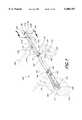
- FIG. 1is a perspective view of a vehicle employing a drive mechanism using linear tracks to provide a rear wheel drive.
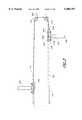
- FIG. 2is a cutaway rear elevational view along the lines 1--1 of the linear tracks shown in FIG. 1.
- FIG. 3is a top plan view of the linear tracks of the vehicle shown in FIG. 1.
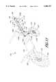
- FIG. 4is perspective view of an alternative embodiment of the invention wherein the vehicle can be ridden by a rider who is resting his chest on a chest rest.
- FIG. 5is a perspective view of an alternative embodiment of the invention wherein two linear tracks are attached to a vehicle at a 90 degree angle in reference to a ground plane.
- FIG. 6is a perspective view of an alternative embodiment of the invention wherein a vehicle is configured to provide a front wheel drive.
- FIG. 7is a front elevational view of a spring loaded pulley which is used in the embodiment of the invention shown in FIG. 6.
- FIG. 8is a perspective view of an alternative embodiment of the invention employing one rotatable driver to provide a rear wheel drive.
- FIG. 9is a cutaway elevational view of the rotatable driver shown in FIG. 8.
- FIG. 10is a side elevational view of the rotatable driver shown in FIG. 8.
- FIG. 11is a perspective view of an alternative embodiment of the invention employing one rotatable driver to a provide a front wheel drive.
- FIG. 1is a perspective view of the vehicle 100.
- the vehicle 100may generally include a frame 102, a drive wheel, such as a rear wheel 104, left and right pedals 105A, 105B, and two linear tracks 107.
- a bicycleis shown, it will be appreciated that, in its broadest form, the principles of the invention are applicable to other vehicles having a driven wheel, such as any vehicle having one or more driven wheels, and one, two, three, four or more total wheels.
- the frame 102may be constructed of suitable strong materials as are well-known in the bicycle art, such as aluminum or steel or their alloys or glass or carbon graphite fibers.
- One embodiment of the frame 102may generally include a front bearing or fork tube 118 in which is journaled a front fork assembly 120.
- the front fork assembly 120includes at its upper end a journal or steerer rotatably mounted in the fork tube 118.
- a front wheel 122is rotatably mounted, such as on a front axle 124, to the lower end of the front fork assembly 120.
- the frame 102includes at least one down tube member, such as down tubes 128, having at its rear end a wheel mount 130 for mounting a rear wheel axle and the rear wheel 104.
- down tubes 128having at its rear end a wheel mount 130 for mounting a rear wheel axle and the rear wheel 104.
- Other frame arrangementsincluding conventional-style bicycle or tricycle frames are also contemplated.
- the frame 102includes a seat 132 for comfortably supporting a rider.
- the seat 132is padded and easily adjustable to accommodate the rider.
- the seat 132can be mounted in front of the rear wheel 104, as illustrated, or may be more conventionally located above the wheels.
- the linear tracks 107are mounted in a desired location, such as on each side of a forward portion 109 of the frame 102.
- the forward portion 109 of the frame 102extends from a forward side of the fork tube 118.
- the linear tracks 107guide the left and right pedals 105A, 105B to travel in a rectilinear motion.
- the connections between the pedals 105A, 105B and the linear tracks 107are described in greater detail in reference to FIGS. 2 and 3.
- the embodiment of the invention disclosed in FIG. 1illustrates the linear tracks 107 in a substantially horizontal position in relation to a ground plane. However, as will be discussed in greater detail in reference to FIG. 5, other positions may be used.
- a flexible elongated linkage 116is connected at a first end 117A to the left pedal and at a second end 117B to the right pedal 105B.
- the linkage 116is routed around a first linkage pulley 134 and a second linkage pulley 136.
- the first and second linkage pulleys 134, 136are located on a first and second side of a forward end of the frame 102, respectively.
- the first and second linkage pulleysmay be substituted with a single pulley.
- the linkage 116may comprise a belt, a chain, or a cable. Further, if the linkage 116 is a belt, the belt may cogged. A cable is preferred.
- a power transmitter 110is provided to transmit power from the pedals to the drive wheel.
- the power transmitter 110can advantageously be a belt, a chain (such as a roller chain) or a cable.
- the beltcan be of any design capable of transmitting power, including a "V" belt and a cogged belt such as the belt material typically used for automotive timing chains.
- the power transmitter 110includes a drive portion and two pedal connection portions 112, 114. At the pedal connection portions 112, 114, the power transmitter 110 is mounted for reciprocating linear motion with respect to the frame 102.
- the drive portion and the at least two pedal connection portions 112, 114may constitute different portions of a single belt or may be two or more belts each connected to pedals 105A and 105B.
- each of the two pedal connection portions 112, 114are respectively located proximate to a first and second end 138, 140 of the power transmitter 110. Further, each of the pedal connection portions 112, 114 are located on the first and second side of the vehicle 100, respectively. From the left pedal 105A, the power transmitter 110 extends to a pulley 142 which is located proximate to the fork tube 118, and then across to a pulley 144 which is located underneath the seat 132. The pulley 144 guides the power transmitter 110 around the first rotatable driver 106 which is rotatably mounted to the wheel mount 130.
- the power transmitter 110From the first rotatable driver 106, the power transmitter 110 extends around a pulley 145 which is centrally positioned along the frame axis and directly in front of the rear wheel 104. The pulley 145 is used to guide the power transmitter 110 around the rear wheel 104. From the pulley 145, the power transmitter 110 extends around a second rotatable driver 108 on a second side of the vehicle. Similar to the first rotatable driver 108, the second rotatable driver 108 is rotatably mounted to the wheel mount 130. Each of the first and second rotatable drivers 106, 108 are rotatably engaged by the drive portion 111 of the power transmitter 110.
- the power transmitter 110From the second rotatable driver 106, the power transmitter 110 extends over a pulley 146 which is situated on a side of the frame 102 opposite the pulley 144 and underneath the seat 132. The power transmitter 110 then extends over a pulley 148 which sits on a side of the frame 102 opposite the pulley 142. The power transmitter 110 then connects to the right pedal 105A proximate to the second end 140 of the power transmitter 110. Together the power transmitter 110 and the linkage 116 provide a closed loop. It is noted, the power transmitter 110 and the linkage 116 may be separate or may together comprise a single member.
- the number and location of the pulleys used to guide the power transmitter 110may be varied. For example, a different pulley configuration may be used to route the power transmitter 110 across different parts of the vehicle 100 depending on the selected frame 102 of the vehicle 100. Exemplary, non-limiting alternative pulley configurations are described in reference to alternative embodiments of the invention, such as are shown in FIGS. 4, 5, 6, 8, and 11.
- the first rotatable driver 106 and the second rotatable driver 108may each include a pulley or sprocket which is rotatably mounted with respect to the frame 102.
- the first and second rotatable drivers 106, 108each engage the rear wheel 104.
- the first rotatable driver 106 and the second rotatable driver 108each include a one way clutch which rotationally couples its respective rotatable driver to the rear wheel 104.
- the first rotatable driver 106is adapted to engage when the power transmitter 110 moves in a first direction
- the second rotatable driver 108is adapted to engage when said power transmitter 110 moves in a second direction opposite to the first direction.
- the power transmitter 110connects pedals 105A and 105B to drive the first and second rotatable drivers 106, 108 such that rearward movement of the left pedal 105A activates or engages the second rotatable driver 108. while the linkage 116 moves the right pedal 105B forward. Similarly, the rearward movement of right pedal 105B rotates or activates the first rotatable driver 106, while the linkage 116 moves the left pedal 105A forward.
- each of the first rotatable driver and the second rotatable driversmay be switched, so the rearward movement of the right pedal 105B engages the second rotatable driver 108, and the rearward movement of the left pedal 105A engages the first rotatable driver 106.
- the first rotatable driver 106 and the second rotatable driver 108may optionally have teeth to engage the power transmitter 110, such as sprocket teeth or cogs that engage a roller chain or a cogged belt.
- FIG. 2is a rear elevational view of the right pedal 105B shown in FIG. 1.
- FIG. 3is a top plan view of the pedal assembly shown in FIG. 1.
- the illustrated pedal and track mechanismis exemplary only, and numerous mechanical equivalents and variations will be apparent to those of skill in the art.
- the right pedal 105Bmay be attached to one of the linear tracks 107 by multiple rollers 202A, 202B, and 202C.
- Each of the linear tracks 107can provide two guide rails 214, 216 (FIG. 2) to support the multiple rollers 202A, 202B, and 202C.
- each of the linear tracks 107houses four rollers. However, it is to be appreciated that fewer or more rollers may be used to engage each of the pedals 105A, 105B to the linear tracks 107.
- the right pedal 105Bis mounted on two posts 204 and 206.
- the two posts 204, 206are rotatably connected to a pedal support member 208 and extend orthogonal from a surface of the pedal support member 208 which is distal to the frame 102.
- the pedal support member 208has at least one aperture (not shown) for the purpose of receiving roller bolts 210A, 210B, and 210C.
- the roller bolts 210A, 210B, 210Crespectively connect the pedal support member 208 to one of multiple rollers 202A, 202B, 202C.
- the second end 117B of the linkage 116may be connected to the pedal support member 208.
- the linkage 116causes, upon the movement of one of the two pedals 105A, 105B in a first direction, the movement of the other pedal in an opposite direction.
- the power transmitter 110Also connected to the rear of pedal support member 208 is the power transmitter 110 (FIG. 3).
- the pedals 105A, 105Bmay use toe clips or may use a standard clipless mechanism (not shown) wherein the rider's standard cycling shoes snap into the pedal 105A, 105B.
- FIGS. 2 and 3also further illustrate that each of the linkage pulleys 134, 136 are rotatably mounted to the frame 102 by a pulley bolt 222 and a pulley nut 224.
- the vehicle 100includes a chest rest 402 for support the chest of a rider (not shown).
- the chest rest 402may be contoured to support the rider's chest. Further, as shown, the chest rest 402 may be in a fixed position on the frame 102 or, the chest rest 402 may be slidably mounted with a mount assembly (not shown) to the remainder of the frame 102. Similar to the embodiment illustrated in FIG. 1, the vehicle 100 has linear tracks 107 positioned at an approximately 45 degree angle in reference to a ground plane.
- Each of the ends 138, 140 of the power transmitter 110is connected to one of the pedals 105A, 105B. From the pedal 105A, the power transmitter 110 extends to the pulley 142. The pulley 142 guides the power transmitter 110 in a downward direction to a first rotatable driver 302 mounted on a bottom end of a rear wheel support member 404. From the first rotatable driver 302, the power transmitter 110 extends upward and around a pulley 306 which is mounted on a rear side of the rear wheel support member 404. The power transmitter 110 then extends downward to a second rotatable driver 308, the second rotatable driver 308 being mounted on the bottom end of the rear wheel support member 404. From the second rotatable driver 308, the power transmitter 110 extends around the pulley 148 and finally connects to the right pedal 105B.
- the first rotatable driver 302 and the second rotatable driver 308each include a one way clutch.
- the one way clutchmay be implemented by using a roller clutch, a pawl and ratchet, a freewheel, or any other conventional drive mechanism that engages in one rotational direction but not the other.
- the movement of the power transmitter 110 (FIG. 4) in the first directionengages the first rotatable driver 302 to drive the rear wheel 104 in a forward direction.
- the movement of the power transmitter 110 in the second directionengages the second rotatable driver 308 to drive the rear wheel 104 in a forward direction.
- each of the pedalsare linked such that the movement of one of the pedals 105A, 105B in one direction causes the other pedal to move in an opposite direction.
- FIG. 5a scooter using the linear tracks 107 of the present invention is illustrated.
- the linear tracks 107are mounted on the frame 102 in an approximately vertical position in relation to the ground plane.
- the vehicle 100 of FIG. 5does not include a seat since the rider propels the vehicle 100 from a standing position.
- each of the ends 138, 140 of the power transmitter 110are connected to one of the pedals 105A, 105B.
- the power transmitter 110extends to the pulley 142.
- the pulley 142guides the power transmitter 110 in a downward direction to a first rotatable driver 302 mounted on a bottom end of the rear wheel support member 404.
- the power transmitter 110extends upward and around the pulley 306 which is mounted on a front side of the rear wheel support member 404.
- the power transmitter 110then extends downward to a second rotatable driver 308, the second rotatable driver 308 being mounted on the bottom end of the rear wheel support member 404.
- the power transmitter 110extends around a pulley 148 and finally connects to the right pedal 105B.
- the handlebars 126may be configured to be adjustable to a height which is comfortable to a rider which is standing on the left and right pedals 105A, 105B. It is noted that in other embodiments of the invention, the linear tracks 107 may be mounted at an angle between 0 and 90 degrees in reference to the ground plane.
- FIG. 6illustrates an alternative embodiment of the invention which employs a front wheel drive. Similar to the embodiment illustrated in FIG. 1, the vehicle 100 has linear tracks 107 mounted on the frame 102 in an approximately horizontal position. For purposes of simplicity, only the differences between the embodiment of the invention shown in FIG. 1 are described.
- each of the ends 138, 140 of the power transmitter 110is connected to one of the pedals 105A, 105B.
- the power transmitter 10extends to the pulley 142.
- the pulley 142guides the power transmitter 110 in a downward direction to a first rotatable driver 302 mounted on a bottom end of the front fork assembly 120.
- the power transmitter 110extends upward and around the pulley 306 which is mounted on a front side of the fork tube 118.
- the power transmitter 110then extends downward to a second rotatable driver 308, the second rotatable driver 308 being mounted on the bottom end of the front fork assembly 120.
- the power transmitter 110extends around a pulley 148 and finally connects to the right pedal 105B.
- the first rotatable driver 302 driver and the second rotatable driver 308each include a one way clutch.
- the one way clutchmay be implemented by using a roller clutch, a pawl and ratchet, a freewheel, or any other conventional drive mechanism that engages in one rotational direction but not the other.
- each of the pedals 105A, 105Bare linked such that the movement of one of the pedals 105A, 105B in one direction causes the other pedal to move in an opposite direction.
- FIG. 7is a front elevational view of the spring loaded pulley 306 which is shown in FIG. 6.
- the spring loaded pulley 306generally includes a pulley 702, a pulley base 704 having an elongated aperture, and a spring 706.
- the spring 706is connected at an upper end to the fork tube 118 by a fastening device 708, such as a screw. Opposite to the connection to the fork tube 118, the spring 706 attaches to the pulley base 704.
- the pulley 702is slidingly engaged to the pulley base 704 via a slot 705 which is centrally positioned on the pulley base 704 so as to allow the pulley 702 to move in a vertical direction.
- the spring loaded pulley 306provides slack to the power transmitter 110 when the front fork assembly 120 is turned to the left or to the right.
- the pulley base 704is fastened to the fork tube by a second fastening device 710.
- FIG. 8another alternative embodiment of the invention which uses a rotatable driver 800 to drive a wheel in a forward motion upon the movement of the power transmitter 110 is disclosed. Similar to the embodiment illustrated in FIG. 1, the vehicle 100 has linear tracks 107 mounted on the frame 102 in an approximately horizontal position. (As discussed above, positions other than horizontal are also contemplated.) For purposes of simplicity, only the differences between the embodiment of the invention shown in FIG. 1 are described.
- the power transmitter 110extends over a pulley 802 which is situated in a horizontal position proximate to the rear of the seat 132. From the pulley 802, the power transmitter 110 extends around the rotatable driver 800 which is rotatably mounted on the wheel mount 130. The power transmitter 110 then extends over a pulley 804 which is mounted to the frame 102 proximate to the underside of the seat 132. From the pulley 804, the power transmitter 110 continues to extend to pulley 148.
- the operation of the left and right pedals 105A, 105B in relation to the linear tracks 106are identical to the embodiment of the invention described in reference to FIG. 1.
- the movement of the power transmitter 110 in each of the first and second directionscauses the rotatable driver 800 to drive the rear wheel 104 in a forward direction.
- the rotatable driver 800may be implemented using various engaging mechanisms, such as by using multiple roller clutches, conventional freewheels, or by using a pawl and ratchet system.
- FIGS. 9 and 10describe in further detail one such embodiment that implements the rotatable driver to include two one way roller clutches.
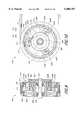
- FIGS. 9 and 10detailed views of the rotatable driver 800 are disclosed.
- FIG. 9shows a rear cut-away elevational view of the rotatable driver 800
- FIG. 10shows a cutaway side elevational view of the rotatable driver 800.
- the rotatable driver 800includes a pulley 902 which is engaged by the power transmitter 110.
- the rotatable driver 800includes two driving mechanisms to drive the wheel 104 (FIG. 8) upon the movement of the power transmitter 110 in a first direction 908 and a second direction 910.
- the first direction 908is generally directed toward a rear portion of the vehicle 100
- the second direction 910is generally directed toward a forward portion of the vehicle 100.
- An outer side of the pulley 902is coupled to a first one way roller clutch 912.
- the first one way roller clutch 912When the pulley 902 rotates in the second direction 910, the first one way roller clutch 912 is disengaged from powering the wheel 104 (FIG. 8). However, when the pulley 902 rotates in the first direction 908, the pulley 902 engages or activates the first one way roller clutch 912. When activated, the first one way roller clutch 912 engages a ring gear 914 having a plurality of teeth on an inner perimeter, the ring gear 914 being located proximate to an inner surface of the first one way roller clutch 912, the inner surface being opposite to the pulley 902.
- the ring gear 914is coupled with three large planet gears 916A, 916B, 916C.
- Each of the large planet gears 916A, 916B, 916Care spaced an equal distance apart from each other on an inner surface of the ring gear 914 which is opposite to the pulley 902.
- Each of the large planet gears 916A, 916B, 916Care fixedly coaxially attached to one of three small planet gears 918A, 918B, and 918C.
- the large planet gear 916A and the small planet gear 918Aare each rotationally engaged to a planet gear axle 920A.
- the large planet gear 916B and the small planet gear 918Bare rotationally engaged to a planet gear axle 920B.
- the large planet gear 916C and the small planet gear 918Care rotationally engaged to a planet gear axle 920C.
- the rotatable driver 800may be adapted to include more or less large and small planet gears.
- the planet gear axles 920A, 920B and 920Ceach extend at a ninety degree angle from a surface of a support disc 922.
- the support disc 922is fixed to an axle 926 or frame 102 and is non-rotational.
- Each of the three small planets gears 918A, 918B, 918Cengage a sun gear 928.
- the sun gear 928is fixedly attached to a rotating member 929 which drives the wheel 104 (FIG. 8).
- a plurality of ball bearings 930are used to facilitate the movement of the rotating member 929.
- a second one way roller clutch 940is coupled to the inner side of the pulley 902.
- the second one way roller clutch 940is adapted to be engaged by the movement of the pulley 902 when the pulley is moved in the second direction 910.
- the second one way roller clutch 940is engaged to an outer edge of an annular connecting member 942.
- the connecting member 942is fixedly attached to the rotating member 929.
- the power transmitter 110when the power transmitter 110 is moving in a first direction 908, the power transmitter 110 drives the pulley 902 in a similar direction, and thereby causes a counter-clockwise movement of the pulley 902.
- the movement of the pulley in a counter-clockwise movementengages the first roller clutch 912 to similarly move in a counter-clockwise direction.
- the movement of the first one way roller clutch 912 in the counter-clockwise directionengages the large planet gears 916A, 916B, 916C and the small planet gears 918A, 918B, and 918C to rotate in a counter-clockwise direction.
- each of the small planet gears 918A, 918B, and 918Cengages the sun gear 928 to rotate in a clock-wise direction.
- the sun gear 928engages the rotating member 929 to drive the wheel 104 (FIG. 8) in a forward motion.
- the second one way roller clutch 940when the power transmitter 110 is moving in a second direction 910, the second one way roller clutch 940 is engaged and rotates in a clockwise direction.
- the second one way roller clutch 940engages the connecting member 942 to similarly rotate in a clockwise direction.
- the rotation of the connecting member 942 in a clockwise directionalso causes the rotating member 929 to drive in a clockwise direction.
- the wheel 104(FIG. 8) is driven in a forward motion upon the movement of the power transmitter 110 in the first and second directions 908, 910.
- FIG. 11illustrates yet another embodiment of the invention using a front wheel drive.
- the power transmitter 110extends from the first end 138 to a pulley 1100 which is connected to the first side of the vehicle 100 proximate to the fork tube 118. From the pulley 1100, the power transmitter 110 extends to a pulley 1102 which is situated on a back side of the front fork assembly 120.
- the pulley 1102guides the power transmitter 110 to a rotatable driver 1104 which is mounted on the bottom end of the front fork assembly 120.
- the rotatable driver 1104may be configured similarly to the rotatable driver described in reference to FIGS. 9 and 10, or may alternatively employ a different driving mechanism.
- the power transmitter 10extends to a pulley 1106 which is situated on the forward portion 109 of the frame 102 proximate to the fork tube 118. From the pulley 1106, the power transmitter 110 extends to connect to the right pedal 105B.
- the rotatable driver 1104engages the front wheel 122 in a forward direction upon the motion of the power transmitter 110 in the first and second direction. Similar to the rotatable driver 800 of FIG. 8, the rotating member 1104 may be implemented by using two one way roller clutches, such as is described in reference to FIGS. 9 and 10. It is noted, the pulleys 1102 and 1106 may each be configured as a spring loaded pulley such as is shown in FIG. 7.
- the linear drive system of the inventionsolves several problems which are commonly associated with traditional drive solutions.
- the linear drive system of the inventionprovides a rider with the ability to power the vehicle upon the forward and backward stroke of the vehicle.
- the stroke of a rideris almost 100% efficient. This is to be contrasted with many rotary drive systems in which only a 30-50% efficiency is achieved.
- an adjustable length strokeis possible. For example, a rider may want to shorten and quicken the stroke when ascending a hill, and may want to lengthen the stroke when traveling downhill.
- the great leverage the rider is able to generate in all embodimentsproduces a faster vehicle with quicker acceleration.
- the linear drive systemutilizes more large leg muscles than rotary drives, activating the hamstrings and gluteals, further increasing speed and acceleration.
- the linear drive actionis more comfortable and less fatiguing than rotary powered systems.
Landscapes
- Engineering & Computer Science (AREA)
- Mechanical Engineering (AREA)
- General Engineering & Computer Science (AREA)
- Chemical & Material Sciences (AREA)
- Combustion & Propulsion (AREA)
- Transportation (AREA)
- Automatic Cycles, And Cycles In General (AREA)
Abstract
Description
Claims (36)
Priority Applications (8)
| Application Number | Priority Date | Filing Date | Title |
|---|---|---|---|
| US09/109,362US6000707A (en) | 1997-09-02 | 1998-07-02 | Linear driving apparatus |
| CA002305550ACA2305550A1 (en) | 1997-10-16 | 1998-10-14 | Linear driving apparatus |
| AU10869/99AAU1086999A (en) | 1997-10-16 | 1998-10-14 | Linear driving apparatus |
| KR1020007004086AKR20010031165A (en) | 1997-10-16 | 1998-10-14 | Linear driving apparatus |
| PCT/US1998/021726WO1999019202A1 (en) | 1997-10-16 | 1998-10-14 | Linear driving apparatus |
| JP2000515792AJP2001519288A (en) | 1997-10-16 | 1998-10-14 | Linear drive |
| EP98953519AEP1023217A1 (en) | 1997-10-16 | 1998-10-14 | Linear driving apparatus |
| CN98811829ACN1280539A (en) | 1997-10-16 | 1998-10-14 | Linear driving apparatus |
Applications Claiming Priority (4)
| Application Number | Priority Date | Filing Date | Title |
|---|---|---|---|
| US5604597P | 1997-09-02 | 1997-09-02 | |
| US6286097P | 1997-10-16 | 1997-10-16 | |
| US6262097P | 1997-10-22 | 1997-10-22 | |
| US09/109,362US6000707A (en) | 1997-09-02 | 1998-07-02 | Linear driving apparatus |
Publications (1)
| Publication Number | Publication Date |
|---|---|
| US6000707Atrue US6000707A (en) | 1999-12-14 |
Family
ID=27489775
Family Applications (1)
| Application Number | Title | Priority Date | Filing Date |
|---|---|---|---|
| US09/109,362Expired - LifetimeUS6000707A (en) | 1997-09-02 | 1998-07-02 | Linear driving apparatus |
Country Status (1)
| Country | Link |
|---|---|
| US (1) | US6000707A (en) |
Cited By (78)
| Publication number | Priority date | Publication date | Assignee | Title |
|---|---|---|---|---|
| US6155584A (en)* | 1996-06-28 | 2000-12-05 | Dallet; Etienne | Man-propelled vehicle, such as in particular a cycle |
| US6554309B2 (en) | 2000-09-22 | 2003-04-29 | Peter Thir | Bicycle pedaling power unit with leverage shifting |
| US6609724B1 (en)* | 1999-07-07 | 2003-08-26 | Emil Dzvonik | Human-powered cycle which is ridden while lying down |
| US20030176247A1 (en)* | 2002-03-15 | 2003-09-18 | Gottschalk Joseph Herbert | Human-powered drive system |
| US20030173755A1 (en)* | 2002-03-18 | 2003-09-18 | John Lachenmayer | Bicycle drive mechanism |
| EP1375333A1 (en)* | 2002-06-21 | 2004-01-02 | Jeng, Fu-shen | Vehicle with energy generating mechanism |
| US20050098977A1 (en)* | 2003-11-06 | 2005-05-12 | Stephane Paquette | Recumbent cycle with a single stroke linear pedaling system |
| US20050113210A1 (en)* | 1997-09-02 | 2005-05-26 | Miller Donald C. | Continuously variable transmission |
| US20050119092A1 (en)* | 2001-04-26 | 2005-06-02 | Miller Donald C. | Continuously variable transmission |
| US20060121842A1 (en)* | 2004-12-02 | 2006-06-08 | Worland Jeffrey L | Multi-sash fume hood drive system |
| US20060181050A1 (en)* | 2005-02-14 | 2006-08-17 | Moreno Jose A | Occupant Propelled Transportation Vehicle |
| US7114737B1 (en)* | 2004-04-02 | 2006-10-03 | C. Martin Rasmussen | Recumbent vehicle |
| US20060264281A1 (en)* | 2005-05-17 | 2006-11-23 | Chin-Chuo Chuo | Bicycle crank speed change sprocket module |
| US7166056B2 (en) | 2003-02-28 | 2007-01-23 | Fallbrook Technologies Inc. | Continuously variable transmission |
| US7166052B2 (en) | 2003-08-11 | 2007-01-23 | Fallbrook Technologies Inc. | Continuously variable planetary gear set |
| US20070049449A1 (en)* | 2005-03-18 | 2007-03-01 | James Klassen | Power transfer device |
| US20070084305A1 (en)* | 2005-10-18 | 2007-04-19 | Pal Anadish K | Pedal-wound step-conveying devices |
| US7214159B2 (en) | 2003-08-11 | 2007-05-08 | Fallbrook Technologies Inc. | Continuously variable planetary gear set |
| US20070245846A1 (en)* | 2006-01-30 | 2007-10-25 | Oronde Armstrong | System for manipulating a continuously variable transmission |
| ES2285962A1 (en)* | 2007-04-30 | 2007-11-16 | Iñigo Azkorra Elexpe | Transmission and conversion mechanism for alternating, opposed linear movement in two poles unidirectional turn and continuous load, has activating element generating vertical movement opposing other activating element |
| WO2007139297A1 (en)* | 2006-05-30 | 2007-12-06 | Keun Bong Hong | Driving apparatus for bicycle |
| US20070295301A1 (en)* | 2006-04-29 | 2007-12-27 | Klassen James B | Energy transfer machine with inner rotor |
| FR2906217A1 (en)* | 2006-09-27 | 2008-03-28 | Raymond Laurent | Vehicle e.g. cycle, has pedals constituted of lengthy and broad plates, and alternatively actuated by weight or muscular force of user, where downward movement of one pedal actuates rising movement of other pedal and vice-versa |
| US7455617B2 (en) | 2004-07-21 | 2008-11-25 | Fallbrook Technologies Inc. | Rolling traction planetary drive |
| US7600963B2 (en) | 2005-08-22 | 2009-10-13 | Viryd Technologies Inc. | Fluid energy converter |
| US7600771B2 (en) | 2006-05-11 | 2009-10-13 | Catadon Systems Llc | Continuously variable drivetrain |
| US7632203B2 (en) | 2005-10-28 | 2009-12-15 | Fallbrook Technologies Inc. | Electromotive drives |
| US7670243B2 (en) | 2005-08-24 | 2010-03-02 | Fallbrook Technologies, Inc. | Continuously variable transmission |
| US7762919B2 (en) | 2004-10-05 | 2010-07-27 | Fallbrook Technologies Inc. | Continuously variable transmission |
| WO2010143987A1 (en) | 2009-06-08 | 2010-12-16 | Universidade Do Porto | Device for propelling vehicles |
| US7871353B2 (en) | 2005-12-09 | 2011-01-18 | Fallbrook Technologies Inc. | Continuously variable transmission |
| US7914029B2 (en) | 2005-11-22 | 2011-03-29 | Fallbrook Technologies Inc. | Continuously variable transmission |
| US20110271777A1 (en)* | 2009-01-16 | 2011-11-10 | Brian Beard | Drive mechanism |
| GB2480233A (en)* | 2010-05-06 | 2011-11-16 | James Martin Terry-Short | Pedal powered power source |
| US8167759B2 (en) | 2008-10-14 | 2012-05-01 | Fallbrook Technologies Inc. | Continuously variable transmission |
| US8215654B1 (en)* | 2010-01-11 | 2012-07-10 | Leser Walter P | Linear to rotary drive system for bicycles and similar vehicles |
| US8313404B2 (en) | 2007-02-16 | 2012-11-20 | Fallbrook Intellectual Property Company Llc | Infinitely variable transmissions, continuously variable transmissions, methods, assemblies, subassemblies, and components therefor |
| US8313405B2 (en) | 2008-02-29 | 2012-11-20 | Fallbrook Intellectual Property Company Llc | Continuously and/or infinitely variable transmissions and methods therefor |
| US8321097B2 (en) | 2007-12-21 | 2012-11-27 | Fallbrook Intellectual Property Company Llc | Automatic transmissions and methods therefor |
| US8317651B2 (en) | 2008-05-07 | 2012-11-27 | Fallbrook Intellectual Property Company Llc | Assemblies and methods for clamping force generation |
| US8360917B2 (en) | 2009-04-16 | 2013-01-29 | Fallbrook Intellectual Property Company Llc | Continuously variable transmission |
| US8376903B2 (en) | 2006-11-08 | 2013-02-19 | Fallbrook Intellectual Property Company Llc | Clamping force generator |
| US8398518B2 (en) | 2008-06-23 | 2013-03-19 | Fallbrook Intellectual Property Company Llc | Continuously variable transmission |
| ES2405035A1 (en)* | 2011-11-14 | 2013-05-29 | Helíades MARTÍ BALLESTÉ | System for actuating human-powered vehicles and human-powered vehicle comprising said system |
| US8469856B2 (en) | 2008-08-26 | 2013-06-25 | Fallbrook Intellectual Property Company Llc | Continuously variable transmission |
| US8480529B2 (en) | 2006-06-26 | 2013-07-09 | Fallbrook Intellectual Property Company Llc | Continuously variable transmission |
| US8738255B2 (en) | 2007-02-01 | 2014-05-27 | Fallbrook Intellectual Property Company Llc | Systems and methods for control of transmission and/or prime mover |
| US8818661B2 (en) | 2008-08-05 | 2014-08-26 | Fallbrook Intellectual Property Company Llc | Methods for control of transmission and prime mover |
| US8845485B2 (en) | 2011-04-04 | 2014-09-30 | Fallbrook Intellectual Property Company Llc | Auxiliary power unit having a continuously variable transmission |
| US8888643B2 (en) | 2010-11-10 | 2014-11-18 | Fallbrook Intellectual Property Company Llc | Continuously variable transmission |
| US8900085B2 (en) | 2007-07-05 | 2014-12-02 | Fallbrook Intellectual Property Company Llc | Continuously variable transmission |
| US8996263B2 (en) | 2007-11-16 | 2015-03-31 | Fallbrook Intellectual Property Company Llc | Controller for variable transmission |
| US9273760B2 (en) | 2007-04-24 | 2016-03-01 | Fallbrook Intellectual Property Company Llc | Electric traction drives |
| US9360089B2 (en) | 2010-03-03 | 2016-06-07 | Fallbrook Intellectual Property Company Llc | Infinitely variable transmissions, continuously variable transmissions, methods, assemblies, subassemblies, and components therefor |
| US9359034B2 (en) | 2012-01-12 | 2016-06-07 | Recreation Systems, Inc. | Cycle and associated components |
| US9371894B2 (en) | 2007-02-12 | 2016-06-21 | Fallbrook Intellectual Property Company Llc | Continuously variable transmissions and methods therefor |
| WO2016130003A1 (en) | 2015-02-11 | 2016-08-18 | Conscious Development Company | A drive system for a human-powered machine |
| NL2014977B1 (en)* | 2015-02-11 | 2016-10-14 | Conscious Dev Company | A drive system for a human-powered machine. |
| WO2016198064A1 (en)* | 2015-06-12 | 2016-12-15 | Schaeffler Technologies AG & Co. KG | Pedal device having a pedal assembly for driving a vehicle, and vehicle having the pedal device |
| WO2016198057A1 (en)* | 2015-06-12 | 2016-12-15 | Schaeffler Technologies AG & Co. KG | Pedal device having a gearing assembly for driving a vehicle, and vehicle having the pedal device |
| WO2016198063A1 (en)* | 2015-06-12 | 2016-12-15 | Schaeffler Technologies AG & Co. KG | Pedal device having a gearing assembly for driving a vehicle, and vehicle having the pedal device |
| US9611921B2 (en) | 2012-01-23 | 2017-04-04 | Fallbrook Intellectual Property Company Llc | Infinitely variable transmissions, continuously variable transmissions, methods, assemblies, subassemblies, and components therefor |
| US9677650B2 (en) | 2013-04-19 | 2017-06-13 | Fallbrook Intellectual Property Company Llc | Continuously variable transmission |
| US9683638B2 (en) | 2005-12-30 | 2017-06-20 | Fallbrook Intellectual Property Company Llc | Continuously variable gear transmission |
| US9683640B2 (en) | 2008-06-06 | 2017-06-20 | Fallbrook Intellectual Property Company Llc | Infinitely variable transmissions, continuously variable transmissions, methods, assemblies, subassemblies, and components therefor |
| US9945456B2 (en) | 2007-06-11 | 2018-04-17 | Fallbrook Intellectual Property Company Llc | Continuously variable transmission |
| US10047861B2 (en) | 2016-01-15 | 2018-08-14 | Fallbrook Intellectual Property Company Llc | Systems and methods for controlling rollback in continuously variable transmissions |
| US10167046B2 (en) | 2016-01-29 | 2019-01-01 | Cyclazoom, LLC | Vehicle with weight-based drive mechanism |
| US10458526B2 (en) | 2016-03-18 | 2019-10-29 | Fallbrook Intellectual Property Company Llc | Continuously variable transmissions, systems and methods |
| US10858065B1 (en) | 2019-07-26 | 2020-12-08 | Cyclazoom Llc | Linearly actuated vehicle |
| US11174922B2 (en) | 2019-02-26 | 2021-11-16 | Fallbrook Intellectual Property Company Llc | Reversible variable drives and systems and methods for control in forward and reverse directions |
| US11215268B2 (en) | 2018-11-06 | 2022-01-04 | Fallbrook Intellectual Property Company Llc | Continuously variable transmissions, synchronous shifting, twin countershafts and methods for control of same |
| WO2022029296A1 (en)* | 2020-08-06 | 2022-02-10 | Volker Heise | Bicycle-type vehicle |
| US11286018B1 (en) | 2019-07-26 | 2022-03-29 | Cyclazoom, LLC | Linearly actuated vehicle providing increased force actuation |
| US11312448B1 (en) | 2019-07-26 | 2022-04-26 | Cyclazoom, LLC | Bicycle with force-increasing actuation system |
| US11333228B2 (en)* | 2019-07-01 | 2022-05-17 | Chun-Jong Chang | Reciprocating linear prime mover |
| US11667351B2 (en) | 2016-05-11 | 2023-06-06 | Fallbrook Intellectual Property Company Llc | Systems and methods for automatic configuration and automatic calibration of continuously variable transmissions and bicycles having continuously variable transmission |
| US12442434B2 (en) | 2024-06-04 | 2025-10-14 | Enviolo B.V. | Reversible variable drives and systems and methods for control in forward and reverse directions |
Citations (15)
| Publication number | Priority date | Publication date | Assignee | Title |
|---|---|---|---|---|
| US1500809A (en)* | 1922-12-29 | 1924-07-08 | Giufri Antony | Foot-propelled vehicle |
| US3661404A (en)* | 1969-05-13 | 1972-05-09 | Camille M Bossaer | Bicycle |
| US3891235A (en)* | 1974-07-02 | 1975-06-24 | Cordova James De | Bicycle wheel drive |
| US3954282A (en)* | 1974-07-15 | 1976-05-04 | Hege Advanced Systems Corporation | Variable speed reciprocating lever drive mechanism |
| US4169609A (en)* | 1978-01-26 | 1979-10-02 | Zampedro George P | Bicycle wheel drive |
| US4227712A (en)* | 1979-02-14 | 1980-10-14 | Timber Dick | Pedal driven vehicle |
| US4574649A (en)* | 1982-03-10 | 1986-03-11 | B. D. Yim | Propulsion and speed change mechanism for lever propelled bicycles |
| US4630539A (en)* | 1985-06-24 | 1986-12-23 | The United States Of America As Represented By The Secretary Of The Army | Device for flash suppression of a rocket motor |
| US5125677A (en)* | 1991-01-28 | 1992-06-30 | Ogilvie Frank R | Human powered machine and conveyance with reciprocating pedals |
| US5156412A (en)* | 1991-02-08 | 1992-10-20 | Ohannes Meguerditchian | Rectilinear pedal movement drive system |
| US5236211A (en)* | 1991-02-08 | 1993-08-17 | Ohannes Meguerditchian | Drive system |
| US5451070A (en)* | 1993-05-26 | 1995-09-19 | Lindsay; Stuart M. W. | Treadle drive system with positive engagement clutch |
| US5496051A (en)* | 1994-04-15 | 1996-03-05 | Farmos; George T. | Apparatus for propelling a manually-powered cycle |
| US5601301A (en)* | 1989-12-18 | 1997-02-11 | Liu; Qingshan | Drive system for muscle-powered equipment and vehicles, in particular bicycles |
| US5690346A (en)* | 1995-07-31 | 1997-11-25 | Keskitalo; Antti M. | Human powered drive-mechanism with versatile driving modes |
- 1998
- 1998-07-02USUS09/109,362patent/US6000707A/ennot_activeExpired - Lifetime
Patent Citations (15)
| Publication number | Priority date | Publication date | Assignee | Title |
|---|---|---|---|---|
| US1500809A (en)* | 1922-12-29 | 1924-07-08 | Giufri Antony | Foot-propelled vehicle |
| US3661404A (en)* | 1969-05-13 | 1972-05-09 | Camille M Bossaer | Bicycle |
| US3891235A (en)* | 1974-07-02 | 1975-06-24 | Cordova James De | Bicycle wheel drive |
| US3954282A (en)* | 1974-07-15 | 1976-05-04 | Hege Advanced Systems Corporation | Variable speed reciprocating lever drive mechanism |
| US4169609A (en)* | 1978-01-26 | 1979-10-02 | Zampedro George P | Bicycle wheel drive |
| US4227712A (en)* | 1979-02-14 | 1980-10-14 | Timber Dick | Pedal driven vehicle |
| US4574649A (en)* | 1982-03-10 | 1986-03-11 | B. D. Yim | Propulsion and speed change mechanism for lever propelled bicycles |
| US4630539A (en)* | 1985-06-24 | 1986-12-23 | The United States Of America As Represented By The Secretary Of The Army | Device for flash suppression of a rocket motor |
| US5601301A (en)* | 1989-12-18 | 1997-02-11 | Liu; Qingshan | Drive system for muscle-powered equipment and vehicles, in particular bicycles |
| US5125677A (en)* | 1991-01-28 | 1992-06-30 | Ogilvie Frank R | Human powered machine and conveyance with reciprocating pedals |
| US5156412A (en)* | 1991-02-08 | 1992-10-20 | Ohannes Meguerditchian | Rectilinear pedal movement drive system |
| US5236211A (en)* | 1991-02-08 | 1993-08-17 | Ohannes Meguerditchian | Drive system |
| US5451070A (en)* | 1993-05-26 | 1995-09-19 | Lindsay; Stuart M. W. | Treadle drive system with positive engagement clutch |
| US5496051A (en)* | 1994-04-15 | 1996-03-05 | Farmos; George T. | Apparatus for propelling a manually-powered cycle |
| US5690346A (en)* | 1995-07-31 | 1997-11-25 | Keskitalo; Antti M. | Human powered drive-mechanism with versatile driving modes |
Cited By (245)
| Publication number | Priority date | Publication date | Assignee | Title |
|---|---|---|---|---|
| US6155584A (en)* | 1996-06-28 | 2000-12-05 | Dallet; Etienne | Man-propelled vehicle, such as in particular a cycle |
| US7393302B2 (en) | 1997-09-02 | 2008-07-01 | Fallbrook Technologies Inc. | Continuously variable transmission |
| US7384370B2 (en) | 1997-09-02 | 2008-06-10 | Fallbrook Technologies Inc. | Continuously variable transmission |
| US7427253B2 (en) | 1997-09-02 | 2008-09-23 | Fallbrook Technologies Inc. | Continuously variable transmission |
| US7422541B2 (en) | 1997-09-02 | 2008-09-09 | Fallbrook Technologies Inc. | Continuously variable transmission |
| US7419451B2 (en) | 1997-09-02 | 2008-09-02 | Fallbrook Technologies Inc. | Continuously variable transmission |
| US7410443B2 (en) | 1997-09-02 | 2008-08-12 | Fallbrook Technologies Inc. | Continuously variable transmission |
| US7402122B2 (en) | 1997-09-02 | 2008-07-22 | Fallbrook Technologies Inc. | Continuously variable transmission |
| US20050113210A1 (en)* | 1997-09-02 | 2005-05-26 | Miller Donald C. | Continuously variable transmission |
| US7393303B2 (en) | 1997-09-02 | 2008-07-01 | Fallbrook Technologies Inc. | Continuously variable transmission |
| US7156770B2 (en) | 1997-09-02 | 2007-01-02 | Fallbrook Technologies Inc. | Continuously variable transmission |
| US20050209041A1 (en)* | 1997-09-02 | 2005-09-22 | Miller Donald C | Continuously variable transmission |
| US7320660B2 (en) | 1997-09-02 | 2008-01-22 | Fallbrook Technologies Inc. | Continuously variable transmission |
| US7217219B2 (en) | 1997-09-02 | 2007-05-15 | Fallbrook Technologies Inc. | Continuously variable transmission |
| US7160222B2 (en) | 1997-09-02 | 2007-01-09 | Fallbrook Technologies Inc. | Continuously variable transmission |
| US7163485B2 (en) | 1997-09-02 | 2007-01-16 | Fallbrook Technologies Inc. | Continuously variable transmission |
| US7175564B2 (en) | 1997-09-02 | 2007-02-13 | Fallbrook Technologies Inc. | Continuously variable transmission |
| US6609724B1 (en)* | 1999-07-07 | 2003-08-26 | Emil Dzvonik | Human-powered cycle which is ridden while lying down |
| US6554309B2 (en) | 2000-09-22 | 2003-04-29 | Peter Thir | Bicycle pedaling power unit with leverage shifting |
| US7147586B2 (en) | 2001-04-26 | 2006-12-12 | Fallbrook Technologies Inc. | Continuously variable transmission |
| US7175565B2 (en) | 2001-04-26 | 2007-02-13 | Fallbrook Technologies Inc. | Continuously variable transmission |
| US7510499B2 (en) | 2001-04-26 | 2009-03-31 | Fallbrook Technologies Inc. | Continuously variable transmission |
| US7883442B2 (en) | 2001-04-26 | 2011-02-08 | Fallbrook Technologies Inc. | Continuously variable transmission |
| US20050197231A1 (en)* | 2001-04-26 | 2005-09-08 | Miller Donald C. | Continuously variable transmission |
| US7163486B2 (en) | 2001-04-26 | 2007-01-16 | Fallbrook Technologies Inc. | Continuously variable transmission |
| US20050119092A1 (en)* | 2001-04-26 | 2005-06-02 | Miller Donald C. | Continuously variable transmission |
| US7166057B2 (en) | 2001-04-26 | 2007-01-23 | Fallbrook Technologies Inc. | Continuously variable transmission |
| US7462127B2 (en) | 2001-04-26 | 2008-12-09 | Fallbrook Technologies Inc. | Continuously variable transmission |
| US7192381B2 (en) | 2001-04-26 | 2007-03-20 | Fallbrook Technologies Inc. | Continuously variable transmission |
| US7131930B2 (en) | 2001-04-26 | 2006-11-07 | Fallbrook Technologies Inc. | Continuously variable transmission |
| US7172529B2 (en) | 2001-04-26 | 2007-02-06 | Fallbrook Technologies Inc. | Continuously variable transmission |
| US7175566B2 (en) | 2001-04-26 | 2007-02-13 | Fallbrook Technologies Inc. | Continuously variable transmission |
| US7153233B2 (en) | 2001-04-26 | 2006-12-26 | Fallbrook Technologies Inc. | Continuously variable transmission |
| US20030176247A1 (en)* | 2002-03-15 | 2003-09-18 | Gottschalk Joseph Herbert | Human-powered drive system |
| US20050051992A1 (en)* | 2002-03-18 | 2005-03-10 | John Lachenmayer | Bicycle drive mechanism |
| US20030173755A1 (en)* | 2002-03-18 | 2003-09-18 | John Lachenmayer | Bicycle drive mechanism |
| EP1375333A1 (en)* | 2002-06-21 | 2004-01-02 | Jeng, Fu-shen | Vehicle with energy generating mechanism |
| US7169076B2 (en) | 2003-02-28 | 2007-01-30 | Fallbrook Technologies Inc. | Continuously variable transmission |
| US10428939B2 (en) | 2003-02-28 | 2019-10-01 | Fallbrook Intellectual Property Company Llc | Continuously variable transmission |
| US7198585B2 (en) | 2003-02-28 | 2007-04-03 | Fallbrook Technologies Inc. | Continuously variable transmission |
| US7396209B2 (en) | 2003-02-28 | 2008-07-08 | Fallbrook Technologies Inc. | Continuously variable transmission |
| US8066614B2 (en) | 2003-02-28 | 2011-11-29 | Fallbrook Technologies, Inc. | Continuously variable transmission |
| US7166056B2 (en) | 2003-02-28 | 2007-01-23 | Fallbrook Technologies Inc. | Continuously variable transmission |
| US9732848B2 (en) | 2003-02-28 | 2017-08-15 | Fallbrook Intellectual Property Company Llc | Continuously variable transmission |
| US9046158B2 (en) | 2003-02-28 | 2015-06-02 | Fallbrook Intellectual Property Company Llc | Continuously variable transmission |
| US7686729B2 (en) | 2003-02-28 | 2010-03-30 | Fallbrook Technologies Inc. | Continuously variable transmission |
| US7731615B2 (en) | 2003-02-28 | 2010-06-08 | Fallbrook Technologies Inc. | Continuously variable transmission |
| US7322901B2 (en) | 2003-02-28 | 2008-01-29 | Fallbrook Technologies Inc. | Continuously variable transmission |
| US7232395B2 (en) | 2003-02-28 | 2007-06-19 | Fallbrook Technologies Inc. | Continuously variable transmission |
| US7235031B2 (en) | 2003-02-28 | 2007-06-26 | Fallbrook Technologies Inc. | Continuously variable transmission |
| US7238137B2 (en) | 2003-02-28 | 2007-07-03 | Fallbrook Technologies Inc. | Continuously variable transmission |
| US7238136B2 (en) | 2003-02-28 | 2007-07-03 | Fallbrook Technologies Inc. | Continuously variable transmission |
| US7238138B2 (en) | 2003-02-28 | 2007-07-03 | Fallbrook Technologies Inc. | Continuously variable transmission |
| US7250018B2 (en) | 2003-02-28 | 2007-07-31 | Fallbrook Technologies Inc. | Continuously variable transmission |
| US7727108B2 (en) | 2003-02-28 | 2010-06-01 | Fallbrook Technologies Inc. | Continuously variable transmission |
| US7651437B2 (en) | 2003-02-28 | 2010-01-26 | Fallbrook Technologies Inc. | Continuously variable transmission |
| US7288042B2 (en) | 2003-02-28 | 2007-10-30 | Fallbrook Technologies Inc. | Continuously variable transmission |
| US7198584B2 (en) | 2003-08-11 | 2007-04-03 | Fallbrook Technologies Inc. | Continuously variable planetary gear set |
| US7452297B2 (en) | 2003-08-11 | 2008-11-18 | Fallbrook Technologies Inc. | Continuously variable planetary gear set |
| US7727110B2 (en) | 2003-08-11 | 2010-06-01 | Fallbrook Technologies Inc. | Continuously variable planetary gear set |
| US7214159B2 (en) | 2003-08-11 | 2007-05-08 | Fallbrook Technologies Inc. | Continuously variable planetary gear set |
| US7217215B2 (en) | 2003-08-11 | 2007-05-15 | Miller Donald C | Continuously variable planetary gear set |
| US7204777B2 (en) | 2003-08-11 | 2007-04-17 | Fallbrook Technologies Inc. | Continuously variable planetary gear set |
| US7654928B2 (en) | 2003-08-11 | 2010-02-02 | Fallbrook Technologies Inc. | Continuously variable planetary gear set |
| US7481736B2 (en) | 2003-08-11 | 2009-01-27 | Fallbrook Technologies Inc. | Continuously variable planetary gear set |
| US7201693B2 (en) | 2003-08-11 | 2007-04-10 | Fallbrook Technologies Inc. | Continuously variable planetary gear set |
| US7393300B2 (en) | 2003-08-11 | 2008-07-01 | Fallbrook Technologies Inc. | Continuously variable planetary gear set |
| US7540818B2 (en) | 2003-08-11 | 2009-06-02 | Fallbrook Technologies Inc. | Continuously variable planetary gear set |
| US7201695B2 (en) | 2003-08-11 | 2007-04-10 | Fallbrook Technologies Inc. | Continuously variable planetary gear set |
| US7201694B2 (en) | 2003-08-11 | 2007-04-10 | Fallbrook Technologies Inc. | Continuously variable planetary gear set |
| US7395731B2 (en) | 2003-08-11 | 2008-07-08 | Fallbrook Technologies Inc. | Continuously variable planetary gear set |
| US7470210B2 (en) | 2003-08-11 | 2008-12-30 | Fallbrook Technologies Inc. | Continuously variable planetary gear set |
| US7166052B2 (en) | 2003-08-11 | 2007-01-23 | Fallbrook Technologies Inc. | Continuously variable planetary gear set |
| US7198583B2 (en) | 2003-08-11 | 2007-04-03 | Fallbrook Technologies Inc. | Continuously variable planetary gear set |
| US7198582B2 (en) | 2003-08-11 | 2007-04-03 | Fallbrook Technologies Inc. | Continuously variable planetary gear set |
| US7462123B2 (en) | 2003-08-11 | 2008-12-09 | Fallbrook Technologies Inc. | Continuously variable planetary gear set |
| US7422546B2 (en) | 2003-08-11 | 2008-09-09 | Fallbrook Technologies Inc. | Continuously variable planetary gear set |
| US7455611B2 (en) | 2003-08-11 | 2008-11-25 | Fallbrook Technologies Inc. | Continuously variable planetary gear set |
| US7431677B2 (en) | 2003-08-11 | 2008-10-07 | Fallbrook Technologies Inc. | Continuously variable planetary gear set |
| US7261663B2 (en) | 2003-08-11 | 2007-08-28 | Fallbrook Technologies Inc. | Continuously variable planetary gear set |
| US20050098977A1 (en)* | 2003-11-06 | 2005-05-12 | Stephane Paquette | Recumbent cycle with a single stroke linear pedaling system |
| US7048290B2 (en) | 2003-11-06 | 2006-05-23 | Paquette Stephane | Recumbent cycle with a single stroke linear pedaling system |
| US20070018423A1 (en)* | 2004-04-02 | 2007-01-25 | C. Rasmussen | Recumbent vehicle |
| US7114737B1 (en)* | 2004-04-02 | 2006-10-03 | C. Martin Rasmussen | Recumbent vehicle |
| US7401799B2 (en) | 2004-04-02 | 2008-07-22 | Rasmussen C Martin | Recumbent vehicle |
| US7354055B2 (en) | 2004-04-02 | 2008-04-08 | Rasmussen C Martin | Recumbent vehicle |
| US20060284395A1 (en)* | 2004-04-02 | 2006-12-21 | C. Rasmussen | Recumbent vehicle |
| US7455617B2 (en) | 2004-07-21 | 2008-11-25 | Fallbrook Technologies Inc. | Rolling traction planetary drive |
| US8133149B2 (en) | 2004-10-05 | 2012-03-13 | Fallbrook Technologies Inc. | Continuously variable transmission |
| US8920285B2 (en) | 2004-10-05 | 2014-12-30 | Fallbrook Intellectual Property Company Llc | Continuously variable transmission |
| US7963880B2 (en) | 2004-10-05 | 2011-06-21 | Fallbrook Technologies Inc. | Continuously variable transmission |
| US7967719B2 (en) | 2004-10-05 | 2011-06-28 | Fallbrook Technologies Inc. | Continuously variable transmission |
| US7976426B2 (en) | 2004-10-05 | 2011-07-12 | Fallbrook Technologies Inc. | Continuously variable transmission |
| US10036453B2 (en) | 2004-10-05 | 2018-07-31 | Fallbrook Intellectual Property Company Llc | Continuously variable transmission |
| US8171636B2 (en) | 2004-10-05 | 2012-05-08 | Fallbrook Technologies Inc. | Method of manufacturing a stator of a cage for a continuously variable transmission (CVT) |
| US8066613B2 (en) | 2004-10-05 | 2011-11-29 | Fallbrook Technologies Inc. | Continuously variable transmission |
| US7909727B2 (en) | 2004-10-05 | 2011-03-22 | Fallbrook Technologies Inc. | Continuously variable transmission |
| US7785228B2 (en) | 2004-10-05 | 2010-08-31 | Fallbrook Technologies Inc. | Torsion disc for use in a continuously variable transmission |
| US8123653B2 (en) | 2004-10-05 | 2012-02-28 | Fallbrook Technologies Inc. | Continuously variable transmission |
| US7762920B2 (en) | 2004-10-05 | 2010-07-27 | Fallbrook Technologies Inc. | Continuously variable transmission |
| US7762919B2 (en) | 2004-10-05 | 2010-07-27 | Fallbrook Technologies Inc. | Continuously variable transmission |
| US20060121842A1 (en)* | 2004-12-02 | 2006-06-08 | Worland Jeffrey L | Multi-sash fume hood drive system |
| US20060181050A1 (en)* | 2005-02-14 | 2006-08-17 | Moreno Jose A | Occupant Propelled Transportation Vehicle |
| US20070049449A1 (en)* | 2005-03-18 | 2007-03-01 | James Klassen | Power transfer device |
| US7344468B2 (en)* | 2005-05-17 | 2008-03-18 | Chin-Chuo Chuo | Bicycle crank speed change sprocket module |
| US20060264281A1 (en)* | 2005-05-17 | 2006-11-23 | Chin-Chuo Chuo | Bicycle crank speed change sprocket module |
| US7600963B2 (en) | 2005-08-22 | 2009-10-13 | Viryd Technologies Inc. | Fluid energy converter |
| US7670243B2 (en) | 2005-08-24 | 2010-03-02 | Fallbrook Technologies, Inc. | Continuously variable transmission |
| US20070084305A1 (en)* | 2005-10-18 | 2007-04-19 | Pal Anadish K | Pedal-wound step-conveying devices |
| US7828685B2 (en) | 2005-10-28 | 2010-11-09 | Fallbrook Technologies Inc. | Electromotive drives |
| US7727101B2 (en) | 2005-10-28 | 2010-06-01 | Fallbrook Technologies Inc. | Electromotive drives |
| US9506562B2 (en) | 2005-10-28 | 2016-11-29 | Fallbrook Intellectual Property Company Llc | Electromotive drives |
| US7632203B2 (en) | 2005-10-28 | 2009-12-15 | Fallbrook Technologies Inc. | Electromotive drives |
| US9950608B2 (en) | 2005-10-28 | 2018-04-24 | Fallbrook Intellectual Property Company Llc | Electromotive drives |
| US9022889B2 (en) | 2005-10-28 | 2015-05-05 | Fallbrook Intellectual Property Company Llc | Electromotive drives |
| US8070635B2 (en) | 2005-10-28 | 2011-12-06 | Fallbrook Technologies Inc. | Electromotive drives |
| US8708360B2 (en) | 2005-11-22 | 2014-04-29 | Fallbrook Intellectual Property Company Llc | Continuously variable transmission |
| US9341246B2 (en) | 2005-11-22 | 2016-05-17 | Fallbrook Intellectual Property Company Llc | Continuously variable transmission |
| US9709138B2 (en) | 2005-11-22 | 2017-07-18 | Fallbrook Intellectual Property Company Llc | Continuously variable transmission |
| US10711869B2 (en) | 2005-11-22 | 2020-07-14 | Fallbrook Intellectual Property Company Llc | Continuously variable transmission |
| US7914029B2 (en) | 2005-11-22 | 2011-03-29 | Fallbrook Technologies Inc. | Continuously variable transmission |
| US10208840B2 (en) | 2005-12-09 | 2019-02-19 | Fallbrook Intellectual Property Company Llc | Continuously variable transmission |
| US8317650B2 (en) | 2005-12-09 | 2012-11-27 | Fallbrook Intellectual Property Company Llc | Continuously variable transmission |
| US7959533B2 (en) | 2005-12-09 | 2011-06-14 | Fallbrook Technologies Inc. | Continuously variable transmission |
| US9121464B2 (en) | 2005-12-09 | 2015-09-01 | Fallbrook Intellectual Property Company Llc | Continuously variable transmission |
| US7871353B2 (en) | 2005-12-09 | 2011-01-18 | Fallbrook Technologies Inc. | Continuously variable transmission |
| US11454303B2 (en) | 2005-12-09 | 2022-09-27 | Fallbrook Intellectual Property Company Llc | Continuously variable transmission |
| US8262536B2 (en) | 2005-12-09 | 2012-09-11 | Fallbrook Intellectual Property Company Llc | Continuously variable transmission |
| US11598397B2 (en) | 2005-12-30 | 2023-03-07 | Fallbrook Intellectual Property Company Llc | Continuously variable gear transmission |
| US9683638B2 (en) | 2005-12-30 | 2017-06-20 | Fallbrook Intellectual Property Company Llc | Continuously variable gear transmission |
| US8776633B2 (en) | 2006-01-30 | 2014-07-15 | Fallbrook Intellectual Property Company Llc | System for manipulating a continuously variable transmission |
| US20070245846A1 (en)* | 2006-01-30 | 2007-10-25 | Oronde Armstrong | System for manipulating a continuously variable transmission |
| US7882762B2 (en) | 2006-01-30 | 2011-02-08 | Fallbrook Technologies Inc. | System for manipulating a continuously variable transmission |
| US20070295301A1 (en)* | 2006-04-29 | 2007-12-27 | Klassen James B | Energy transfer machine with inner rotor |
| US8011345B2 (en) | 2006-04-29 | 2011-09-06 | Klassen James B | Energy transfer machine with inner rotor |
| US7503307B2 (en) | 2006-04-29 | 2009-03-17 | Klassen James B | Energy transfer machine with inner rotor |
| US7600771B2 (en) | 2006-05-11 | 2009-10-13 | Catadon Systems Llc | Continuously variable drivetrain |
| WO2007139297A1 (en)* | 2006-05-30 | 2007-12-06 | Keun Bong Hong | Driving apparatus for bicycle |
| US8480529B2 (en) | 2006-06-26 | 2013-07-09 | Fallbrook Intellectual Property Company Llc | Continuously variable transmission |
| US9726282B2 (en) | 2006-06-26 | 2017-08-08 | Fallbrook Intellectual Property Company Llc | Continuously variable transmission |
| US9017207B2 (en) | 2006-06-26 | 2015-04-28 | Fallbrook Intellectual Property Company Llc | Continuously variable transmission |
| FR2906217A1 (en)* | 2006-09-27 | 2008-03-28 | Raymond Laurent | Vehicle e.g. cycle, has pedals constituted of lengthy and broad plates, and alternatively actuated by weight or muscular force of user, where downward movement of one pedal actuates rising movement of other pedal and vice-versa |
| US9086145B2 (en) | 2006-11-08 | 2015-07-21 | Fallbrook Intellectual Property Company Llc | Clamping force generator |
| US8376903B2 (en) | 2006-11-08 | 2013-02-19 | Fallbrook Intellectual Property Company Llc | Clamping force generator |
| US9878719B2 (en) | 2007-02-01 | 2018-01-30 | Fallbrook Intellectual Property Company Llc | Systems and methods for control of transmission and/or prime mover |
| US8738255B2 (en) | 2007-02-01 | 2014-05-27 | Fallbrook Intellectual Property Company Llc | Systems and methods for control of transmission and/or prime mover |
| US9328807B2 (en) | 2007-02-01 | 2016-05-03 | Fallbrook Intellectual Property Company Llc | Systems and methods for control of transmission and/or prime mover |
| US9676391B2 (en) | 2007-02-01 | 2017-06-13 | Fallbrook Intellectual Property Company Llc | Systems and methods for control of transmission and/or prime mover |
| US10703372B2 (en) | 2007-02-01 | 2020-07-07 | Fallbrook Intellectual Property Company Llc | Systems and methods for control of transmission and/or prime mover |
| US9371894B2 (en) | 2007-02-12 | 2016-06-21 | Fallbrook Intellectual Property Company Llc | Continuously variable transmissions and methods therefor |
| US10260607B2 (en) | 2007-02-12 | 2019-04-16 | Fallbrook Intellectual Property Company Llc | Continuously variable transmissions and methods therefor |
| US8313404B2 (en) | 2007-02-16 | 2012-11-20 | Fallbrook Intellectual Property Company Llc | Infinitely variable transmissions, continuously variable transmissions, methods, assemblies, subassemblies, and components therefor |
| US9239099B2 (en) | 2007-02-16 | 2016-01-19 | Fallbrook Intellectual Property Company Llc | Infinitely variable transmissions, continuously variable transmissions, methods, assemblies, subassemblies, and components therefor |
| US10094453B2 (en) | 2007-02-16 | 2018-10-09 | Fallbrook Intellectual Property Company Llc | Infinitely variable transmissions, continuously variable transmissions, methods, assemblies, subassemblies, and components therefor |
| US8585528B2 (en) | 2007-02-16 | 2013-11-19 | Fallbrook Intellectual Property Company Llc | Infinitely variable transmissions, continuously variable transmissions, methods, assemblies, subassemblies, and components therefor |
| US9574643B2 (en) | 2007-04-24 | 2017-02-21 | Fallbrook Intellectual Property Company Llc | Electric traction drives |
| US10056811B2 (en) | 2007-04-24 | 2018-08-21 | Fallbrook Intellectual Property Company Llc | Electric traction drives |
| US9273760B2 (en) | 2007-04-24 | 2016-03-01 | Fallbrook Intellectual Property Company Llc | Electric traction drives |
| ES2285962B1 (en)* | 2007-04-30 | 2009-04-01 | Iñigo Azkorra Elexpe | TRANSMISSION AND CONVERSION MECHANISM OF ALTERNATE AND INVESTED LINEAR MOVEMENT IN TWO-POLE MOVEMENTS OF UNIDIRECTIONAL TURN AND CONTINUOUS LOAD. |
| ES2285962A1 (en)* | 2007-04-30 | 2007-11-16 | Iñigo Azkorra Elexpe | Transmission and conversion mechanism for alternating, opposed linear movement in two poles unidirectional turn and continuous load, has activating element generating vertical movement opposing other activating element |
| US9945456B2 (en) | 2007-06-11 | 2018-04-17 | Fallbrook Intellectual Property Company Llc | Continuously variable transmission |
| US8900085B2 (en) | 2007-07-05 | 2014-12-02 | Fallbrook Intellectual Property Company Llc | Continuously variable transmission |
| US9869388B2 (en) | 2007-07-05 | 2018-01-16 | Fallbrook Intellectual Property Company Llc | Continuously variable transmission |
| US10260629B2 (en) | 2007-07-05 | 2019-04-16 | Fallbrook Intellectual Property Company Llc | Continuously variable transmission |
| US10100927B2 (en) | 2007-11-16 | 2018-10-16 | Fallbrook Intellectual Property Company Llc | Controller for variable transmission |
| US8996263B2 (en) | 2007-11-16 | 2015-03-31 | Fallbrook Intellectual Property Company Llc | Controller for variable transmission |
| US11125329B2 (en) | 2007-11-16 | 2021-09-21 | Fallbrook Intellectual Property Company Llc | Controller for variable transmission |
| US8626409B2 (en) | 2007-12-21 | 2014-01-07 | Fallbrook Intellectual Property Company Llc | Automatic transmissions and methods therefor |
| US9739375B2 (en) | 2007-12-21 | 2017-08-22 | Fallbrook Intellectual Property Company Llc | Automatic transmissions and methods therefor |
| US10704687B2 (en) | 2007-12-21 | 2020-07-07 | Fallbrook Intellectual Property Company Llc | Automatic transmissions and methods therefor |
| US9249880B2 (en) | 2007-12-21 | 2016-02-02 | Fallbrook Intellectual Property Company Llc | Automatic transmissions and methods therefor |
| US8321097B2 (en) | 2007-12-21 | 2012-11-27 | Fallbrook Intellectual Property Company Llc | Automatic transmissions and methods therefor |
| US9850993B2 (en) | 2008-02-29 | 2017-12-26 | Fallbrook Intellectual Property Company Llc | Continuously and/or infinitely variable transmissions and methods therefor |
| US9182018B2 (en) | 2008-02-29 | 2015-11-10 | Fallbrook Intellectual Property Company Llc | Continuously and/or infinitely variable transmissions and methods therefor |
| US8313405B2 (en) | 2008-02-29 | 2012-11-20 | Fallbrook Intellectual Property Company Llc | Continuously and/or infinitely variable transmissions and methods therefor |
| US8317651B2 (en) | 2008-05-07 | 2012-11-27 | Fallbrook Intellectual Property Company Llc | Assemblies and methods for clamping force generation |
| US9618100B2 (en) | 2008-05-07 | 2017-04-11 | Fallbrook Intellectual Property Company Llc | Assemblies and methods for clamping force generation |
| US9683640B2 (en) | 2008-06-06 | 2017-06-20 | Fallbrook Intellectual Property Company Llc | Infinitely variable transmissions, continuously variable transmissions, methods, assemblies, subassemblies, and components therefor |
| US10634224B2 (en) | 2008-06-06 | 2020-04-28 | Fallbrook Intellectual Property Company Llc | Infinitely variable transmissions, continuously variable transmissions, methods, assemblies, subassemblies, and components therefor |
| US8641572B2 (en) | 2008-06-23 | 2014-02-04 | Fallbrook Intellectual Property Company Llc | Continuously variable transmission |
| US9528561B2 (en) | 2008-06-23 | 2016-12-27 | Fallbrook Intellectual Property Company Llc | Continuously variable transmission |
| US10066713B2 (en) | 2008-06-23 | 2018-09-04 | Fallbrook Intellectual Property Company Llc | Continuously variable transmission |
| US9074674B2 (en) | 2008-06-23 | 2015-07-07 | Fallbrook Intellectual Property Company Llc | Continuously variable transmission |
| US8398518B2 (en) | 2008-06-23 | 2013-03-19 | Fallbrook Intellectual Property Company Llc | Continuously variable transmission |
| US9365203B2 (en) | 2008-08-05 | 2016-06-14 | Fallbrook Intellectual Property Company Llc | Systems and methods for control of transmission and/or prime mover |
| US9878717B2 (en) | 2008-08-05 | 2018-01-30 | Fallbrook Intellectual Property Company Llc | Systems and methods for control of transmission and/or prime mover |
| US8818661B2 (en) | 2008-08-05 | 2014-08-26 | Fallbrook Intellectual Property Company Llc | Methods for control of transmission and prime mover |
| US9903450B2 (en) | 2008-08-26 | 2018-02-27 | Fallbrook Intellectual Property Company Llc | Continuously variable transmission |
| US10704657B2 (en) | 2008-08-26 | 2020-07-07 | Fallbrook Intellectual Property Company Llc | Continuously variable transmission |
| US8852050B2 (en) | 2008-08-26 | 2014-10-07 | Fallbrook Intellectual Property Company Llc | Continuously variable transmission |
| US8469856B2 (en) | 2008-08-26 | 2013-06-25 | Fallbrook Intellectual Property Company Llc | Continuously variable transmission |
| US10253880B2 (en) | 2008-10-14 | 2019-04-09 | Fallbrook Intellectual Property Company Llc | Continuously variable transmission |
| US9574642B2 (en) | 2008-10-14 | 2017-02-21 | Fallbrook Intellectual Property Company Llc | Continuously variable transmission |
| US8167759B2 (en) | 2008-10-14 | 2012-05-01 | Fallbrook Technologies Inc. | Continuously variable transmission |
| US8870711B2 (en) | 2008-10-14 | 2014-10-28 | Fallbrook Intellectual Property Company Llc | Continuously variable transmission |
| US20110271777A1 (en)* | 2009-01-16 | 2011-11-10 | Brian Beard | Drive mechanism |
| US8967022B2 (en)* | 2009-01-16 | 2015-03-03 | Brian Beard | Drive mechanism |
| CN102282392A (en)* | 2009-01-16 | 2011-12-14 | 布赖恩·比尔德 | Exercise device with linear drive mechanism |
| US8360917B2 (en) | 2009-04-16 | 2013-01-29 | Fallbrook Intellectual Property Company Llc | Continuously variable transmission |
| US9920823B2 (en) | 2009-04-16 | 2018-03-20 | Fallbrook Intellectual Property Company Llc | Continuously variable transmission |
| US10746270B2 (en) | 2009-04-16 | 2020-08-18 | Fallbrook Intellectual Property Company Llc | Continuously variable transmission |
| US9279482B2 (en) | 2009-04-16 | 2016-03-08 | Fallbrook Intellectual Property Company Llc | Continuously variable transmission |
| US8663050B2 (en) | 2009-04-16 | 2014-03-04 | Fallbrook Intellectual Property Company Llc | Continuously variable transmission |
| WO2010143987A1 (en) | 2009-06-08 | 2010-12-16 | Universidade Do Porto | Device for propelling vehicles |
| US8215654B1 (en)* | 2010-01-11 | 2012-07-10 | Leser Walter P | Linear to rotary drive system for bicycles and similar vehicles |
| US10066712B2 (en) | 2010-03-03 | 2018-09-04 | Fallbrook Intellectual Property Company Llc | Infinitely variable transmissions, continuously variable transmissions, methods, assemblies, subassemblies, and components therefor |
| US9360089B2 (en) | 2010-03-03 | 2016-06-07 | Fallbrook Intellectual Property Company Llc | Infinitely variable transmissions, continuously variable transmissions, methods, assemblies, subassemblies, and components therefor |
| GB2480233A (en)* | 2010-05-06 | 2011-11-16 | James Martin Terry-Short | Pedal powered power source |
| US10197147B2 (en) | 2010-11-10 | 2019-02-05 | Fallbrook Intellectual Property Company Llc | Continuously variable transmission |
| US8888643B2 (en) | 2010-11-10 | 2014-11-18 | Fallbrook Intellectual Property Company Llc | Continuously variable transmission |
| US9291251B2 (en) | 2010-11-10 | 2016-03-22 | Fallbrook Intellectual Property Company Llc | Continuously variable transmission |
| US8845485B2 (en) | 2011-04-04 | 2014-09-30 | Fallbrook Intellectual Property Company Llc | Auxiliary power unit having a continuously variable transmission |
| ES2405035A1 (en)* | 2011-11-14 | 2013-05-29 | Helíades MARTÍ BALLESTÉ | System for actuating human-powered vehicles and human-powered vehicle comprising said system |
| US9359034B2 (en) | 2012-01-12 | 2016-06-07 | Recreation Systems, Inc. | Cycle and associated components |
| US10428915B2 (en) | 2012-01-23 | 2019-10-01 | Fallbrook Intellectual Property Company Llc | Infinitely variable transmissions, continuously variable transmissions, methods, assemblies, subassemblies, and components therefor |
| US9611921B2 (en) | 2012-01-23 | 2017-04-04 | Fallbrook Intellectual Property Company Llc | Infinitely variable transmissions, continuously variable transmissions, methods, assemblies, subassemblies, and components therefor |
| US10323732B2 (en) | 2013-04-19 | 2019-06-18 | Fallbrook Intellectual Property Company Llc | Continuously variable transmission |
| US9677650B2 (en) | 2013-04-19 | 2017-06-13 | Fallbrook Intellectual Property Company Llc | Continuously variable transmission |
| WO2016130003A1 (en) | 2015-02-11 | 2016-08-18 | Conscious Development Company | A drive system for a human-powered machine |
| NL2014977B1 (en)* | 2015-02-11 | 2016-10-14 | Conscious Dev Company | A drive system for a human-powered machine. |
| WO2016198064A1 (en)* | 2015-06-12 | 2016-12-15 | Schaeffler Technologies AG & Co. KG | Pedal device having a pedal assembly for driving a vehicle, and vehicle having the pedal device |
| WO2016198057A1 (en)* | 2015-06-12 | 2016-12-15 | Schaeffler Technologies AG & Co. KG | Pedal device having a gearing assembly for driving a vehicle, and vehicle having the pedal device |
| WO2016198063A1 (en)* | 2015-06-12 | 2016-12-15 | Schaeffler Technologies AG & Co. KG | Pedal device having a gearing assembly for driving a vehicle, and vehicle having the pedal device |
| US11306818B2 (en) | 2016-01-15 | 2022-04-19 | Fallbrook Intellectual Property Company Llc | Systems and methods for controlling rollback in continuously variable transmissions |
| US10047861B2 (en) | 2016-01-15 | 2018-08-14 | Fallbrook Intellectual Property Company Llc | Systems and methods for controlling rollback in continuously variable transmissions |
| US10920882B2 (en) | 2016-01-15 | 2021-02-16 | Fallbrook Intellectual Property Company Llc | Systems and methods for controlling rollback in continuously variable transmissions |
| US10167046B2 (en) | 2016-01-29 | 2019-01-01 | Cyclazoom, LLC | Vehicle with weight-based drive mechanism |
| US10875599B2 (en) | 2016-01-29 | 2020-12-29 | Cyclazoom, LLC | Vehicle with weight-based drive mechanism |
| US11718365B2 (en) | 2016-01-29 | 2023-08-08 | Cyclazoom, LLC | Vehicle with pedals movable along sliders |
| US10458526B2 (en) | 2016-03-18 | 2019-10-29 | Fallbrook Intellectual Property Company Llc | Continuously variable transmissions, systems and methods |
| US12145690B2 (en) | 2016-05-11 | 2024-11-19 | Enviolo B.V. | Systems and methods for automatic configuration and automatic calibration of continuously variable transmissions and bicycles having continuously variable transmissions |
| US11667351B2 (en) | 2016-05-11 | 2023-06-06 | Fallbrook Intellectual Property Company Llc | Systems and methods for automatic configuration and automatic calibration of continuously variable transmissions and bicycles having continuously variable transmission |
| US11215268B2 (en) | 2018-11-06 | 2022-01-04 | Fallbrook Intellectual Property Company Llc | Continuously variable transmissions, synchronous shifting, twin countershafts and methods for control of same |
| US12173778B2 (en) | 2018-11-06 | 2024-12-24 | Enviolo B.V. | Continuously variable transmissions, synchronous shifting, twin countershafts and methods for control of same |
| US11624432B2 (en) | 2018-11-06 | 2023-04-11 | Fallbrook Intellectual Property Company Llc | Continuously variable transmissions, synchronous shifting, twin countershafts and methods for control of same |
| US11174922B2 (en) | 2019-02-26 | 2021-11-16 | Fallbrook Intellectual Property Company Llc | Reversible variable drives and systems and methods for control in forward and reverse directions |
| US11530739B2 (en) | 2019-02-26 | 2022-12-20 | Fallbrook Intellectual Property Company Llc | Reversible variable drives and systems and methods for control in forward and reverse directions |
| US12000458B2 (en) | 2019-02-26 | 2024-06-04 | Fallbrook Intellectual Property Company Llc | Reversible variable drives and systems and methods for control in forward and reverse directions |
| US11333228B2 (en)* | 2019-07-01 | 2022-05-17 | Chun-Jong Chang | Reciprocating linear prime mover |
| US11440615B2 (en) | 2019-07-26 | 2022-09-13 | Cyclazoom, LLC | Linearly actuated vehicle with coiling power link |
| US11312448B1 (en) | 2019-07-26 | 2022-04-26 | Cyclazoom, LLC | Bicycle with force-increasing actuation system |
| US11286018B1 (en) | 2019-07-26 | 2022-03-29 | Cyclazoom, LLC | Linearly actuated vehicle providing increased force actuation |
| US10858065B1 (en) | 2019-07-26 | 2020-12-08 | Cyclazoom Llc | Linearly actuated vehicle |
| WO2022029296A1 (en)* | 2020-08-06 | 2022-02-10 | Volker Heise | Bicycle-type vehicle |
| US12442434B2 (en) | 2024-06-04 | 2025-10-14 | Enviolo B.V. | Reversible variable drives and systems and methods for control in forward and reverse directions |
Similar Documents
| Publication | Publication Date | Title |
|---|---|---|
| US6000707A (en) | Linear driving apparatus | |
| US4928986A (en) | Arm and leg powered cycle | |
| US8517405B2 (en) | Human powered vehicle with two reciprocal pedals | |
| AU747397B2 (en) | Improved pedaling mechanism for bicycles and the like | |
| US5236211A (en) | Drive system | |
| US5192089A (en) | Pedal-operated scooter | |
| US5280936A (en) | Human powered vehicle and drive system | |
| US7753386B2 (en) | Steering mechanism and method for a manually powered vehicle | |
| US20070228687A1 (en) | Bicycle propulsion mechanism | |
| US5067738A (en) | Child powered bicycle trailer | |
| WO1999019202A1 (en) | Linear driving apparatus | |
| US6554309B2 (en) | Bicycle pedaling power unit with leverage shifting | |
| US4270766A (en) | Arm and leg powered drive system for a vehicle | |
| US20030173755A1 (en) | Bicycle drive mechanism | |
| JP2016506890A (en) | Propulsion system for vehicles that move manually | |
| US20080106061A1 (en) | Drive apparatus | |
| US8632089B1 (en) | Mechanism for converting reciprocal motion to rotary motion | |
| KR100374294B1 (en) | Man powered vehicle with at least two wheels | |
| US5876053A (en) | Conveyer drive system | |
| US20080271551A1 (en) | Drive Apparatus | |
| US6749211B1 (en) | Bicycle with reciprocal pedal levers having shiftable pivot axis for transmission ratio change | |
| JPS5881882A (en) | Bicycle | |
| WO1994018059A1 (en) | Row bicycle apparatus | |
| WO2006110389A1 (en) | Common axis drive and shift system | |
| US11312448B1 (en) | Bicycle with force-increasing actuation system |
Legal Events
| Date | Code | Title | Description |
|---|---|---|---|
| AS | Assignment | Owner name:LINEAR BICYCLES, INC., CALIFORNIA Free format text:ASSIGNMENT OF ASSIGNORS INTEREST;ASSIGNOR:MILLER, DONALD C.;REEL/FRAME:009439/0855 Effective date:19980826 | |
| STCF | Information on status: patent grant | Free format text:PATENTED CASE | |
| AS | Assignment | Owner name:MOTION TECHNOLOGIES, LLC, CALIFORNIA Free format text:ASSIGNMENT OF ASSIGNORS INTEREST;ASSIGNOR:U.S. MOTION SYSTEMS, INC.;REEL/FRAME:011682/0344 Effective date:20010318 | |
| AS | Assignment | Owner name:MOTION TECHNOLOGIES, LLC, CALIFORNIA Free format text:ASSIGNMENT OF ASSIGNORS INTEREST;ASSIGNOR:MOTION SYSTEMS, INC.;REEL/FRAME:012722/0519 Effective date:20020315 | |
| FPAY | Fee payment | Year of fee payment:4 | |
| FEPP | Fee payment procedure | Free format text:PAT HOLDER NO LONGER CLAIMS SMALL ENTITY STATUS, ENTITY STATUS SET TO UNDISCOUNTED (ORIGINAL EVENT CODE: STOL); ENTITY STATUS OF PATENT OWNER: LARGE ENTITY | |
| REFU | Refund | Free format text:REFUND - PAYMENT OF MAINTENANCE FEE, 8TH YR, SMALL ENTITY (ORIGINAL EVENT CODE: R2552); ENTITY STATUS OF PATENT OWNER: LARGE ENTITY | |
| AS | Assignment | Owner name:FALLBROOK TECHNOLOGIES INC., CALIFORNIA Free format text:CONVERSION OF CA LLC TO DE INC.;ASSIGNOR:MOTION TECHNOLOGIES, LLC;REEL/FRAME:017458/0996 Effective date:20040413 | |
| FPAY | Fee payment | Year of fee payment:8 | |
| FPAY | Fee payment | Year of fee payment:12 | |
| AS | Assignment | Owner name:NGEN III, L.P., CALIFORNIA Free format text:SECURITY AGREEMENT;ASSIGNOR:FALLBROOK TECHNOLOGIES INC.;REEL/FRAME:027620/0783 Effective date:20120125 | |
| AS | Assignment | Owner name:SILICON VALLEY BANK, CALIFORNIA Free format text:SECURITY AGREEMENT;ASSIGNOR:FALLBROOK TECHNOLOGIES INC.;REEL/FRAME:027830/0217 Effective date:20120307 | |
| AS | Assignment | Owner name:FALLBROOK TECHNOLOGIES INC., CALIFORNIA Free format text:RELEASE BY SECURED PARTY;ASSIGNOR:NGEN III, L.P.;REEL/FRAME:028639/0872 Effective date:20120725 | |
| AS | Assignment | Owner name:FALLBROOK INTELLECTUAL PROPERTY COMPANY LLC, CALIF Free format text:ASSIGNMENT OF ASSIGNORS INTEREST;ASSIGNOR:FALLBROOK TECHNOLOGIES INC.;REEL/FRAME:028651/0085 Effective date:20120725 | |
| AS | Assignment | Owner name:FALLBROOK TECHNOLOGIES, INC., CALIFORNIA Free format text:RELEASE;ASSIGNOR:SILICON VALLEY BANK;REEL/FRAME:028796/0140 Effective date:20120726 | |
| AS | Assignment | Owner name:CONTI TEMIC MICROELECTRONIC GMBH, GERMANY Free format text:LICENSE;ASSIGNOR:FALLBROOK INTELLECTUAL PROPERTY COMPANY LLC.;REEL/FRAME:043837/0903 Effective date:20160823 | |
| AS | Assignment | Owner name:CONTI TEMIC MICROELECTRONIC GMBH, GERMANY Free format text:CORRECTIVE ASSIGNMENT TO CORRECT THE PATENT NUMBERS 8700214 AND 9239090 PREVIOUSLY RECORDED ON REEL 043837 FRAME 0903. ASSIGNOR(S) HEREBY CONFIRMS THE LICENSE;ASSIGNOR:FALLBROOK INTELLECTUAL PROPERTY COMPANY LLC.;REEL/FRAME:045059/0903 Effective date:20160823 | |
| AS | Assignment | Owner name:FALLBROOK INTELLECTUAL PROPERTY COMPANY LLC, TEXAS Free format text:LICENSE;ASSIGNOR:CONTI TEMIC MICROELECTRONIC GMBH;REEL/FRAME:059853/0560 Effective date:20200804 Owner name:FALLBROOK TECHNOLOGIES, INC., TEXAS Free format text:LICENSE;ASSIGNOR:CONTI TEMIC MICROELECTRONIC GMBH;REEL/FRAME:059853/0560 Effective date:20200804 | |
| AS | Assignment | Owner name:ENVIOLO INC., TEXAS Free format text:ASSIGNMENT OF ASSIGNORS INTEREST;ASSIGNOR:FALLBROOK INTELLECTUAL PROPERTY COMPANY LLC;REEL/FRAME:068511/0716 Effective date:20240401 Owner name:ENVIOLO INTERNATIONAL INC., TEXAS Free format text:ASSIGNMENT OF ASSIGNORS INTEREST;ASSIGNOR:ENVIOLO INC.;REEL/FRAME:068098/0023 Effective date:20240401 Owner name:ENVIOLO B.V., NETHERLANDS Free format text:ASSIGNMENT OF ASSIGNORS INTEREST;ASSIGNOR:ENVIOLO INTERNATIONAL INC.;REEL/FRAME:067964/0001 Effective date:20240401 |