US6000612A - Portable data collection device having optical character recognition - Google Patents
Portable data collection device having optical character recognitionDownload PDFInfo
- Publication number
- US6000612A US6000612AUS08/949,073US94907397AUS6000612AUS 6000612 AUS6000612 AUS 6000612AUS 94907397 AUS94907397 AUS 94907397AUS 6000612 AUS6000612 AUS 6000612A
- Authority
- US
- United States
- Prior art keywords
- image
- character
- dataform
- imaging
- assembly
- Prior art date
- Legal status (The legal status is an assumption and is not a legal conclusion. Google has not performed a legal analysis and makes no representation as to the accuracy of the status listed.)
- Expired - Lifetime
Links
Images


Classifications
- G—PHYSICS
- G06—COMPUTING OR CALCULATING; COUNTING
- G06K—GRAPHICAL DATA READING; PRESENTATION OF DATA; RECORD CARRIERS; HANDLING RECORD CARRIERS
- G06K7/00—Methods or arrangements for sensing record carriers, e.g. for reading patterns
- G06K7/10—Methods or arrangements for sensing record carriers, e.g. for reading patterns by electromagnetic radiation, e.g. optical sensing; by corpuscular radiation
- G06K7/10544—Methods or arrangements for sensing record carriers, e.g. for reading patterns by electromagnetic radiation, e.g. optical sensing; by corpuscular radiation by scanning of the records by radiation in the optical part of the electromagnetic spectrum
- G06K7/10712—Fixed beam scanning
- G06K7/10722—Photodetector array or CCD scanning
- G—PHYSICS
- G06—COMPUTING OR CALCULATING; COUNTING
- G06V—IMAGE OR VIDEO RECOGNITION OR UNDERSTANDING
- G06V30/00—Character recognition; Recognising digital ink; Document-oriented image-based pattern recognition
- G06V30/10—Character recognition
Definitions
- the present inventionrelates to a portable dataform reader capable of recognizing characters within an image capture area.
- Portable data collection devicesare widely used in manufacturing, service and package delivery industries to perform a variety of on-site data collection activities. Such portable data collection devices often include integrated bar code dataform readers adapted to read bar code dataforms affixed to products, product packaging and/or containers in warehouses, retail stores, shipping terminals, etc. for inventory control, tracking, production control and expediting, quality assurance and other purposes.
- Various bar code dataform readershave been proposed for portable data collection devices including laser scanners and one dimensional (1D) charge coupled device (CCD) imaging assemblies, both of which are capable of reading 1 D bar code dataforms, that is, bar codes consisting of a single row of contrasting black bars and white spaces of varying widths.
- Both laser scanners and CCD imaging assembliesare also capable of reading a "stacked" two dimensional (2D) bar code dataforms, such as PDF417, which is comprised of a plurality of adjacent rows of bar code data.
- the stacked 2D bar code PDF417includes row indicator patterns utilized by the dataform reader for vertical synchronization to permit reading successive rows of bar code data.
- a two dimensional (2D) imaging based dataform readerhas been proposed in U.S. application Ser. No. 08/544,618, filed Oct. 18, 1995 and entitled "Extended Working Range Dataform Reader Including Fuzzy Logic Image Control Circuitry".
- 08/544,618,which is assigned to the assignee of the present application, includes an imaging assembly having a two dimensional array of photosensors adapted to read 2D bar code dataforms (e.g., PDF417, SuperCode, etc.) with vertical synchronization row indicator patterns as well as matrix dataforms (e.g., MaxiCode, DataMatrix, etc.) which do not include vertical synchronization patterns.
- the individual photosensorscorrespond to image picture elements or pixels of the resulting image generated with the photosensors are read out after an exposure period or periods.
- the 2D dataform reader disclosed in application Ser. No. 08/544,618utilizes an open loop feedback control system including fuzzy logic circuitry to determine proper exposure time and gain parameters for a camera assembly.
- Application Ser. No. 08/544,618is incorporated in its entirety herein by reference.
- optical character recognition systemsoperate in conjunction with fixed station flat bed scanners.
- a documentis placed on the scanner and feed past a scanning head by a document handler.
- Such systemsoperate using fixed document illumination, fixed focusing, and a fixed platform for document handling.
- a fixed station optical character recognition systemmakes image segmentation, edge detection, and picture binarization easier to perform. Characters read by the scanner are less likely to be distorted and misoriented.
- Such a scanning systemincreases the inter-class variance, decreases the interior-class variance and increases the recognition accuracy.
- the present inventionrelates to non-touch hand-held optical character recognition systems. Such systems provide greater flexibility in use but at a cost of increased character recognition complexity.
- a hand-held scanner suitable for general optical character recognitionmust be able to recognize characters anywhere on a document or print media, in any orientation and in a variety of illumination settings.
- a portable data collection device constructed in accordance with the present inventionincludes a housing that defines an internal region and includes a user handle that allows a user to position the housing relative to an indicia carrying target.
- An imaging assemblyincludes a two dimensional imaging array supported within the internal region of the portable hand-held housing.
- the imaging assemblyincludes a capture circuit that generates a video signal representative of an image of a target zone.
- An optics assembly supported by the housingfocuses an image of the target area onto the photosensor array.
- a character recognition processing circuitreceives the video signal and categorizes the indicia on the target into a set of predefined characters.
- the character recognition processing circuitincludes a discriminator for identifying a text region of the target and identifying individual character regions within the text region and a categorizer for identifying a character from a set of possible characters for an individual character region. The categorizer performs one or more tests based on pixel data within the individual character region.
- a preferred classifieris built in the form of a tree classifier.
- a number of character feature testsare designed to discriminate between different character shapes.
- the values for the functional tests for known characatersare tabulated and then used to create thresholds used to evaluate an unknown character.
- By traversing the tree classifiera given character is identified and then the classifier moves to a next character for recognition. After an entire text region has been determined by classifying the characters the text in ascii form or a similar scheme can be transmitted from the hand held device to a remote location.
- one object of the inventionis an improved hand-held data gathering device for performing optical character recognition. This an other objects, advantages and features of the invention will become understood from a preferred embodiment of the invention which is described in conjunction with the accompanying drawings.
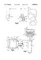
- FIG. 1is a perspective view of a portable data collection device of the present invention with a pivoting member of a viewing assembly in a folded down position;
- FIG. 2is a perspective view of the portable data collection device of FIG. 1 with the viewing assembly pivoting member in an upright position.
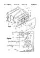
- FIG. 3is a sectional view of a portion of a housing of the portable data collection device of FIG. 1 and the viewing assembly pivoting member in the upright position;
- FIG. 4is a sectional view of a portion of a housing of the portable data collection device of FIG. 1 and the viewing assembly pivoting member in the folded down position;
- FIG. 5is a view partly in side elevation and partly in section showing use of the viewing assembly to aid in aiming the device
- FIG. 6is a top view of the portable data collection device of FIG. 1;
- FIG. 7is a front elevation view of the portable data collection device of FIG. 1 as seen from a plane indicated by the line 7--7 in FIG. 6;
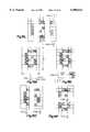
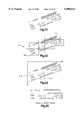
- FIG. 8is a perspective view of a modular camera assembly of an imaging assembly of the portable data collection device of the present invention, the modular portion shown imaging a target dataform affixed to a target item;
- FIG. 9is an exploded perspective view of the modular camera assembly of FIG. 8;
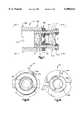
- FIG. 10is a schematic representation of a plurality of lens of an optic assembly of the modular camera assembly
- FIG. 11is a view, partially in side elevation and partially in section of the optic assembly of the modular camera assembly
- FIG. 12is a front elevation view of the optic assembly of the modular camera assembly as seen from a plane indicated by the line 12--12 in FIG. 11;
- FIG. 13is a rear elevation view of the optic assembly of the modular camera assembly as seen from a plane indicated by the line 13--13 in FIG. 11;
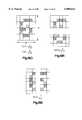
- FIG. 14is an exploded perspective view of an illumination assembly of the modular camera assembly of the imaging assembly of the present invention.
- FIG. 15is a representation of a crosshair illumination pattern generated by the illumination assembly of FIG. 18 superimposed on a target two dimensional bar code dataform;
- FIG. 15Ais an enlarged view of the FIG. 15 representation
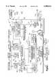
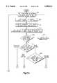
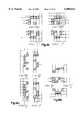
- FIG. 16Ais one portion of a block diagram of selected circuitry of the portable data collection device of the present invention.
- FIG. 16Bis a second portion of a block diagram of selected circuitry of the portable data collection device of the present invention, the second portion matching the first portion shown in FIG. 17A;
- FIGS. 17A and 17Bdepict a flow chart setting forth one operating embodiment of the portable data collection device of the present invention to decode a bar code dataform and capture an image of a target area;
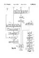
- FIG. 18is a flowchart of the steps performed by the portable data acquisition device in converting text regions of an image into file or a display of text characters;
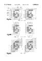
- FIGS. 19A-19Sare a series of character depictions that show test functions for classifying characters captured by the portable data collection device
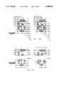
- FIGS. 20A-20Care tabulations for the ten digits of the values derived from the functions described in FIGS. 19A-19S;
- FIG. 21is a flowchart of a tree classifier for determining a character based upon the results of the tests performed by the depictions of FIGS. 19A-19S;
- FIGS. 22-25are different depictions of a text region of an image captured by the portable data collection device.
- the data collection device 10includes a housing 12 defining an interior region.
- the housing 12includes a gripping portion 14 sized to be grasped in the hand of an operator and enlarged head portion 16 extending from the gripping portion 14.
- the enlarged head portion 16includes an opening which exposes one end of a two dimensional (2D) photosensor array imaging assembly 18.
- the imaging assembly 18includes a modular camera assembly 20 and a control and decoder board 22 electrically coupled to electronic circuitry of the modular camera assembly.
- the control and decoder board 22is supported within the gripping portion 14 of the housing 12.
- a power source 24such as a rechargeable battery for supplying operating power to the portable data collection device 10.
- a dataform reading trigger switch or actuator 26extends through an opening in the gripping portion 14. Also extending through a rear opening in the gripping portion 14 is an imaging push button trigger switch or actuator 28.
- the dataform reading trigger 26is positioned to be depressed by an index finger of the operator while the gripping portion 14 of the housing 12 is held in the operator's hand.
- the imaging trigger 28is positioned to be depressed by a thumb of an operator while the gripping portion 14 of the housing 12 is held in the operator's hand.
- the gripping portion 14also includes a small opening that exposes an indicator light emitting diode (LED) 32.
- the indicator LED 32displays three different colors. A color green is displayed by the indicator LED 32 when the device 10 is on standby, ready for use. A color orange is displayed with the device 10 has successfully completed an operation such as decoding a target dataform or imaging a target area. A color red is displayed when the device 10 is not ready to perform an operation.
- the housing 12includes an opening exposing a portion of a microphone 34 mounted in the housing interior region and another opening through which a radio antenna 38 extends.
- a data output port 312also extend through openings in the gripping portion 14. The output port 312 is a serial data output port.
- the interior region of the housing 12supports the imaging assembly 18 and other electronic circuitry to be described below.
- FIGS. 8 and 9show perspective and exploded perspective views of the modular camera assembly 20 of the imaging assembly 18, it can be seen that the modular camera assembly 20 includes a housing 40 which supports an illumination assembly 42 and a board camera assembly 38.
- the board camera assembly 38includes 48 a color photosensor array mounted on a surface 56 of a printed circuit board 54.
- the printed circuit board 54 and another printed circuit board 52support board camera circuitry that, when actuated, generates a composite video signal 262 (FIG. 16B).
- the modular camera assembly 20includes an optic assembly 43 which focuses an image of a target area 44 onto a 2D photosensor array 48 (shown schematically in FIG. 14). Specifically, reflected light from the target area 44 is focused by the optic assembly 43 onto an outwardly facing, light receiving surface 48b of the photosensor array 48.
- the photosensor array 48is part of a surface mounted integrated circuit (IC) chip 48a.
- ICintegrated circuit
- the photosensor array light receiving surface 48bincludes an array of 584 rows by 752 columns of light sensitive photosensors for a total of 439,168 photosensors in the photosensor array.
- An image of the target area 44is focused on the light receiving surface 48b.
- Light incident on a photosensor during an exposure periodcharges the photosensor. Subsequent to the exposure period, the photosensor charge is read out or discharged.
- the charge magnitude or voltage read out from a photosensorrepresents an integration of the intensity of the reflected light focused on the photosensor over the exposure period.
- Each photosensor of the photosensor array 48corresponds to a picture element or pixel of a captured image field or frame.
- the photosensors of the photosensor array 48are read out in a frame mode interlaced format which means at a time t1, photosensors in every other row of the photosensor array are read out (e.g., rows 1, 3, 5, . . . , 581) to generate a first captured image field comprising 219,584 image pixels.
- photosensors in the other rowsare read out (e.g., rows 2, 4, 6, . . ., 582) to generate a second captured image field comprising 219,584 image pixels.
- the images represented in the first and second captured image fields, when appropriately interlaced row by row fashioncomprise a full captured image frame comprising 439,168 image pixels.
- the target area 44is defined by a field of view of the board camera assembly 38 and is represented in FIG. 8 by the dimensions labeled "H" (for height of target area 44) and "W" (for width of the target area 44).
- the illumination assembly 42includes four illumination optic portions 88a, 88b, 88c, 88d which project a uniform intensity distribution of illumination across the target area 44.
- the illumination assembly 42also includes a targeting arrangement including targeting LEDs 64a, 64b, which, when energized, project illumination through first and second targeting optics 72a, 72b thereby generating a crosshair targeting illumination pattern CR (FIG. 14) to aid in aiming the device 10. To avoid image distortion, the targeting pattern CR is turned off by the imaging assembly 18 when the image frames of the target area 44 are being captured.
- the imaging assembly 18is capable of decoding a target dataform 45 (FIG. 5) affixed to an object 46.
- the target dataform 45may be a one dimensional bar code dataform such as Codabar, Code 39, Code 93, Code 128, Interleaved 2 of 5, and UPC/EAN; a two dimensional bar code dataform such as PDF417 and SuperCode; or a matrix dataform such as MaxiCode and DataMatrix.
- the optic assembly 43 of the present inventionis specifically configured to permit reading by the imaging assembly of standard density dataforms having a minimum cell size of 6.6 mils (0.0066 in. or 0.167 mm.).
- the minimum cell size of a dataformis defined as the smallest dimension of a separately readable information conveying portion of the dataform.
- FIG. 15Ashows a DataMatix dataform at 47.
- DataMatrixis a binary symbology of International Data Matrix, Inc. of Clearwater, Fla. and is described in U.S. Pat. No. 5,473,151 to Priddy et al.
- the two visual squares labeled 48a, 48b, with 48a being a dark block and 48b being a light block labeledmay constitute a separately readable information conveying portion of the dataform 47, namely, the letter "B".
- the cell size of the letter “B”would be the horizontal and vertical dimensions labeled "x" and "y” in FIG. 15A.
- the vertical dimension "y”is one half the size of the horizontal dimension "x”.
- the minimum cell size for the letter "B”would be the vertical dimension "y”.
- the imaging assembly 18is capable of capturing an image of the two dimensional target area 44 (FIG. 8).
- the board camera assembly 38includes the rear printed circuit board 52 and the front printed circuit board 54.
- the photosensor array IC chip 48ais disposed on the front surface 56 (FIG. 9) of the front printed circuit board 54.
- the light receiving surface 48b of the photosensor array 48receives reflected illumination from the target area 44 focused through the optic assembly 43.
- the light receiving surface 48b of the photosensor array 48is overlaid by the filter 48c.
- the illumination assembly 42includes a printed circuit board 60, a lens array 62 and two targeting LEDs 64a, 64b.
- the lens array 62functions as the outer or front panel of the modular camera assembly 20.
- a plurality of exposure LEDs 66are disposed on the front surface of printed circuit board 60 to direct illumination through the lens array 62 towards the target area 44.
- the flexible printed circuit board 63which route power to the targeting LEDs 64a, 64b, is also electrically coupled to the circuit board 60.
- the flexible printed circuit board 63has a central unshaped cut out region 63c to provide clearance for the outer shroud 58a of the shroud assembly 57.
- the targeting LEDs 64a, 64bwhen energized, project targeting illumination through openings 68 in the circuit board 60 and through targeting optics of the lens array 62 to form the crosshairs light or illumination pattern CR which aids in aiming the device 10 at the target dataform 45 or target object 46.
- FIG. 10shows a cross section of the camera assembly 38 with the optic assembly 43 focusing an image of the target area 44 onto the photosensor array 48.
- the performance of the portable data collection device 10is enhanced by the optic assembly 43 which enables imaging and decoding of dataforms with a minimum cell size of 6.6 mil (0.168 mm.).
- the optic assembly 43includes a shroud assembly 57 (FIG. 11) and a lens assembly LA (FIG. 10).
- the lens assembly LAincludes lenses L1, L2, L3, L4 and a spacer member SP1 with a small central aperture A1 (1.17 mm. in diameter) all supported within an inner cylindrical shroud 57a (best seen in FIG. 9).
- the lens assembly LAalso includes a lens L5 which is supported by an upper surface of the photosensor array IC chip 48a.
- the shroud assembly 57also includes a lock nut 59a and the outer shroud 58a.
- the lock nut 59aincludes internal threads 59b which thread onto external threads 57b of the inner shroud 57a.
- the lock nut 59afacilitates precise positioning of the lenses L1, L2, L3, L4 of the lens assembly LA with respect to the longitudinal displacement of the lenses along an optical axis labeled A--A in FIG. 10.
- the precise positioning of the lenses L1, L2, L3, L4, L5 with respect to the photosensor array 48permits the sharpest possible image of the target dataform 45 to be directed on the center point CP of the light receiving surface 48b of the photosensor array 48.
- an O-ring 57cis disposed in a annular groove in the outer surface of the inner shroud 57a. The O-ring 57c seals against a central opening 61 of the lens array 62 to prevent external contaminants from entering the interior region 146 of the modular housing 140.
- FIG. 11based on the distance between the optic assembly 43 and the photosensor array 48, for a given dataform minimum cell size or dimension, there exists a best focus position S2 in front of the forward-most surface 90 of the lens L1 of the optic assembly 43 at which an image of the target dataform 45 in the target area 44 will be focused sharpest on a center point CP of the light receiving surface 48b of the photosensor array 48.
- the image sharpnessgradually degrades as the target dataform 45 is moved from the best focus position inwardly towards a near field cut off distance S1 or away toward a far field cut off distance S3.
- the target dataform 45 having the specified minimum cell sizeis still capable of being decoded.
- the imaging assembly 18will no longer be able to decode the target dataform 45.
- the horizontal and vertical angular field of view of optic assembly 43is 32° (horizontal) ⁇ 24° (vertical). This corresponds to a 40° diagonal field of view.
- the horizontal angular field of viewis shown schematically as an angle labeled with reference number 47 in FIG. 14.
- Near field and far field cut off distances S1 and S3are set forth below for a number of different dataform minimum cell sizes. At the S1 and S3 distances, a dataform having the specified minimum cell size can still be decoded by the imaging assembly 18. For a minimum cell size of 15 mil, the S2 best focus working distance is 140 mm. (5.5 in.).
- the preferred optic assembly 43includes four lenses L1, L2, L3, L4 and the plastic spacer member SP1 separating lenses L2 and L3.
- the lenses L1, L2, L3, L4 and the spacer member SP1are supported in the inner shroud 57a of the shroud assembly 57.
- a flat lens L5is mounted on an upper surface of the photosensor array IC chip 48a and overlies the light receiving surface 48b of the photosensor array 48.
- the illumination assembly 42must provide adequate illumination of the target area 44 during the exposure period so that enough reflected light is absorbed by the photosensor array 48 to generate a suitably bright image.
- the exposure periodis normally limited to 0.01 seconds or less to minimize the smear effect of an operator's hand jittering during a dataform reading session. Therefore, the illumination assembly 42 must provide adequate illumination to accommodate the large F# and short exposure time.
- the printed circuit board assembly 60includes a plurality of surface mount exposure illumination LEDs 66.
- a single piece acrylic or polycarbonate lens array 62preferably fabricated of PMMA (polymethyl methacrylate), is positioned between the printed circuit board assembly 60 and the target area 44 (FIGS. 8 and 9) for directing the illumination from the exposure LEDs 66 towards the target area 44.
- the illumination LEDs 66which are set out in four banks of four LEDs, emit a red color light to illuminate the target area 44.
- Suitable red surface mount LEDsare available as Part No. MTSM735K-UR or MTSM745KA-UR from MarkTech Corporation of Latham, N.Y.
- the printed circuit board assembly 60includes printed conductors and conductive leads 196 including a power lead operative for supplying power to the illumination LEDs 66.
- Each illumination LED 66provides illuminosity of 285 milli candela (mcd) over an angular illumination field of about 68 degrees.
- the small footprint of each illumination LED 66enables four LEDs to be placed in a row measuring less than 14 mm.
- the printed circuit board assembly 60includes four banks of four illumination LEDs 66 totaling sixteen illumination LEDs providing at least 4560 mcd of uniform illumination over the target area 44 at the best focus distance S2.
- a central opening 67 in the printed circuit board assembly 60provides an opening for the shroud assembly 58 to extend through.
- the illumination optic portions 88a, 88b, 88c, 88ddirect a 68 degree angular illumination field from each illumination LED 66 into a uniform field having an angular field of view horizontally and vertically which substantially corresponds to the angular field of view horizontally and vertically of the optic assembly 43 which defines the target area 44.
- the targeting LEDs 64a, 64bare turned off by the imaging assembly circuitry 18 during capture of an image frame to reduce possible image distortion caused by glare from the targeting LEDs reflecting off the target object 46.
- the four banks of illumination LEDs 66may be sequentially energized instead of being simultaneously energized to further reduce glare from the target object 46 in the target area 44 of the optic assembly 43. That is at any given point in time, only one bank of illumination LEDs would be energized. After a short predetermined time period, the presently energized bank would be turned off and another bank would be energized for the predetermined time period.
- each bankwould be energized sequentially, being energized 1/4 of the time and off 3/4 of the time.
- Sequential illumination of the four banks of two illumination LEDs 66will have the effect of reducing the overall level of illumination of the target area 44 while still providing for uniformity in illumination throughout the target area.
- sequence of energizationmay be varied so that at any point in time more than one LED bank is energized, for example, sequencing of energization of the LED banks could be altered such that two or three banks of LEDs are energized at any given point in time.
- the color 2D photosensor array 48is part of the board camera assembly 38 and is commercially available from such Sony of Japan.
- the board camera assembly 38when activated in either the dataform reading or imaging mode, generates a composite video signal 262.
- the board camera assembly 38includes a clock generator 256, synchronization signal circuitry 258 and analog signal processing circuitry 260 for reading illumination intensity values out of each photosensor of the photosensor array 48 and generating the composite video signal 262.
- the intensity of light incident on individual photosensors of the photosensor array 48varies somewhat uniformly from very bright (whitest areas of the image of the target area 44) to very dark (darkest areas of the image of the target area 44).
- the preferred photosensor array 48comprises an interlaced 752 by 582 matrix array of photodiode photosensors that define a total of 437,664 pixels.
- the clock generator 256is coupled to a crystal oscillator and generates asynchronous clocking signals to read out charges accumulating on individual photosensors over an exposure period. The charges on the photosensors are read out through CCD elements adjacent the photosensor array photosensors. The charges are converted to a voltage signal 250 (FIG.
- the board camera assembly 38generates the composite analog video signal 262 corresponding to consecutive fields of the image incident on the photosensor array 48.
- the video signal 262is termed "composite” because it includes synchronization signals generated by the synchronization signal circuitry 258 which correlate portions of the video signal to particular photosensor locations, interspersed among image signal portions wherein the signal magnitude represents charges on individual photosensors read out from a given row of the photosensor array 48.
- the board camera assembly 38also includes gain control circuitry 252 for controlling amplification of an image signal 253 and exposure period control circuitry 254 for controlling a duration of an exposure period of the photosensors. Both the exposure period control circuitry 254 and the gain control circuitry 252 are controlled by fuzzy logic exposure parameter control circuitry.
- the synchronization signals 268 generated by synchronization signal circuitry 258, the clock signal 270 generated by the clock generator 256, and the composite video signal 262are output to signal processing circuitry 264 on a control and decoder board 22. Under the control of a microprocessor 266 mounted on the control and decoder board 22, the composite video signal 262 is input to the signal processing circuitry 264 along with the clocking signals 268 and the synchronization signals 270.
- the signal processing circuitry 264includes synchronization extractor circuitry which receives the clocking signals 268 and the synchronization signals 270 and generates signals which are coupled to analog to digital converter circuitry (A/D converter circuitry) 272 causing the A/D converter circuitry to periodically digitize the video signal 262.
- A/D converter circuitryanalog to digital converter circuitry
- the A/D converter circuitry 272includes an A/D converter generating an 8 bit gray scale value for each photosensor read out.
- the 8 bit gray scale illumination value corresponding to a given photosensoris a surrogate measure of the illumination incident on the photosensor over the exposure period prior to the reading out of the photosensor.
- the magnitude of gray valuesranges from 0 (low charge read out from photosensor corresponding to a low illumination level incident on photosensor over the exposure period) to 127 (high charge read out from photosensor corresponding to a high illumination level incident on photosensor over the exposure period).
- Direct memory access (DMA) control circuitry 275receives the synchronization signals 270 and clock signals 268 and generates address signals 276a coupled to a frame buffer memory 274 to indicate a storage location for each value generated by the A/D converter circuitry 272.
- Data signals 276 representing the gray scale values generated by the A/D converter circuitry 272are coupled to the frame buffer memory 274.
- the dataform read trigger circuit 26aWhen an operator institutes a dataform reading session (dataform reading mode) by depressing the dataform reading trigger 26, the dataform read trigger circuit 26a sends a signal to the control and selection circuitry 284 causing the control and selection circuitry to control operation of an image processing circuit 285.
- the image processing circuit 285performs steps outlined below and it is appreciated that many of these steps could also be performed directly by the microprocessor 266.
- the image processing circuitry 285includes binarization circuitry 288 and image processing and decoder circuitry 290 to adjust the magnitudes of selected gray scale values stored in the frame buffer memory 274 and decode the adjusted selected gray scale values.
- the image capture trigger circuit 28acaptures an image.
- the control and selection circuitry 284causes the selection circuitry to identify text regions and actuate a binarization circuit 289 that converts the gray scale values corresponding to a captured image into binarized digital data and stores the binarized data back into the memory 274.
- the binarized digital data for each characteris an array of pixels surrounded by white space. This data (including the bounding white space pixels) is extracted from the frame buffer memory 274 and evaluated to determine what character those pixels represent.
- the characteris typically chosen from a set of characters such as the ascii character set.
- the character data 300is processed by serial output circuitry 296 and made available as a serial stream of data 310 through the serial output port 312 and/or a radio module 314. Note, the optical character recognition that is provided compresses many pixels in an array into a single ascii byte and therefore no data compression is needed.
- control and selection circuitry 284may be appropriately programmed to route the data (either compressed or uncompressed) representing the captured frame directly to the serial output circuitry 296 and the radio module 314.
- the portable data collection device 10is also capable of capturing a verbal message from the operator.
- the control and decoder board 22also includes a voice capture module 304 for capturing and digitizing an operator's verbal message and voice compression circuitry 306 for compressing the captured verbal message.
- the voice capture module 304is coupled to the microphone 34 and is operable by the control and selection circuitry 284 to capture and digitize audio input.
- the voice compression circuitry 306compresses a digitized voice signal.
- Data 308 representing the compressed digitized voice signalis coupled to the serial output circuitry 296.
- Decoded data 298(from either a dataform or decoded character data), compressed image data 300 and compressed digitized voice data 308 are routed to the serial output circuitry 296 which assembles output data 310 for serial output through the serial output port 312 or the radio module 314.
- the serial output port 312is coupled to an input port of a radio module 314 mounted on the control and decoder board 22 (shown schematically in FIG. 14).
- the radio module 314modulates and transmits the output data 310 to a remote device (not shown) where the transmitted data is demodulated.
- the demodulated output datamay be used to update inventory, and/or accounting records, update production control expediting or product tracking files, permit supervisory corrective action to remove/repair damaged items, etc.
- the control and decoder board 22further includes exposure parameters control circuitry 316 which outputs control signals 318, 320 to the exposure period control circuitry 254 and the gain control circuitry 252 of the camera assembly 38 and a signal 322 embodying an appropriate set of reference voltages for operating the A/D converter 272 within the signal processing circuit 264.
- the exposure parameters control circuitry 316includes fuzzy logic circuitry 334 which analyzes captured frames of data accessed from the frame buffer memory 274.
- the fuzzy logic circuitry 324analyzes a captured frame to determines if the current exposure period of the 2D photosensor array 48, the current amplification of the video signal 250 by the gain control circuitry 252 and the reference voltages used by the A/D converter circuitry 272 are resulting in an "acceptable" captured image frame.
- control signal 318is changed to adjust the exposure period of the 2D photosensor array 48 and/or the control signal 320 is changed to adjust the amplification of the video signal 250 and/or the signal 322 is changed to adjust the operation of the A/D converter circuitry 272.
- another captured frameis analyzed by the fuzzy logic circuitry 324 and, if necessary, further adjustments are made in an iterative fashion until the camera assembly 38 produces an "acceptable" captured image.
- a suitable exposure parameter control circuit including fuzzy logic control circuitryis disclosed in U.S. patent application Ser. No. 08/544,618, filed Oct. 18, 1995, entitled “Extended Working Range Dataform Reader Including Fuzzy Logic Image Control Circuitry.” The contents of U.S. Ser. No. 08/544,618 are incorporated in its entirety by reference.
- the power source 24is coupled to the control and decoder board 22 to provide operating power to the microprocessor 266 and other circuitry mounted on the board and the radio module 314.
- Power circuitry 336 under the control of the microprocessor 266is coupled through a lead 338 to the illumination assembly 42 and the board camera assembly 38 to supply power to these components of the imaging assembly 18.
- the flow chart shown in FIGS. 17A and 17Billustrates the operation of the imaging assembly 18 in a dataform decoding mode and an imaging mode.
- a single frame of the image in the target area 44is captured, compressed and output when the operator depressed the imaging trigger 28.
- the flow chart shown in FIG. 32illustrates the operation of the imaging assembly 18 in the dataform decoding mode and in an imaging mode.
- the imaging assembly 18waits for a signal representing either actuation of the imaging trigger 28 or the dataform reading trigger 26 to commence either an image capture session or a dataform reading session.
- the signalmay be generated by the image capture trigger circuit 28a, the dataform reading trigger circuit 26a or by a signal generated by customer specific application software.
- a composite video signalis generated 402, converted to a grey scale image 404 and stored 406 in the frame buffer memory 274.
- the fuzzy logic circuitry 334determines if the captured image frame is acceptable, that is, the image is within predetermined acceptable ranges for brightness and the magnitude of charges on the photosensors of the 2D photosensor array 48. If the fuzzy logic circuitry 334 determines the captured frame is not acceptable, one or more of the operating parameters of the board camera assembly 38 and the A/D converter circuitry 272 are modified as shown at step 410 and the steps 400, 402, and 404 are repeated.
- control and selection circuitry 284determines whether the dataform or image capture input has been activated. If the activation signal is from the dataform reading trigger 26 requiring a dataform decode, at step 414 the gray scale values representing the imaged dataform in the target area 44 are binarized and a dataform image area is identified. The image processing and decoder circuitry 285 reconstructs the image of the dataform via cell extraction 416 and the decoding 418 of the dataform image. At step 420, a determination is made if the decoding was successful.
- the extracted decoded datais output 422 to the serial output circuitry 296 and at step 424, the orange color of the LED indicator 32 is energized for a predetermined time to signal the operator that the dataform 45 in the target area 44 has been successfully read. Subsequently, the imaging assembly 18 is turned off. If at step 420, the decoding was not successful, the process returns to capture another image. The user knows that another image capture is needed since he or she is not given the feedback of the orange color LED indicator.
- control and selection circuitry 284determines that the activation signal is from the imaging trigger 28, at step 426 a determination is made whether the activation is for normal imaging or optical character recognition. If optical character recognition is required, the image is binarized and a character region is identified 428. The optical character recognition is performed 430 and the data is output 432. If full image capture and transmission is needed the image is either binarized and compressed or merely compressed and transmitted. In either event, the LED indicator 32 is energized 424 to display the color orange to signal the operator that the image in the target area 44 has been successfully captured.
- the imaging assembly 18includes the camera board assembly 38 of the modular camera assembly 20 which is electrically coupled to the control and decoder board 22.
- the control and decoder board 22includes the microprocessor 266 and associated circuitry.
- the circuitry of the imaging assembly 18may by embodied in software resident in one or more RAM or ROM memory chips 430 (FIG. 5) mounted on the control and decoder board 22 and operated by the microprocessor 266. Alternately, the circuitry of the imaging assembly 18 may comprise separate application-specific integrated circuitry (ASIC) mounted on the control and decoder board 22.
- ASICapplication-specific integrated circuitry
- the textIn order to extract the text from an image that has been imaged by the portable data collection device 10, certain requirements must be met.
- the textmust be located in a central position of a captured image and there should be blank or white space surrounding all the text.
- a number of processesare performed to provide text area zoning, binarization, rotation and feature selection as well as the actual optical character recognition.
- the flow chart of FIG. 18provides an overview of the process.
- a text area zoning step 510an image is received which is a grey scale image.
- a text area in which all characters to be determined by OCR techniquesis a key area for consideration.
- background regions and regions with graphicsare unnecessary areas which are excluded from consideration.
- the imageis broken up into i rows and j columns of windows. If the size of the windows in pixels is NX*NY, then each window has a size of (NX/I)*(NY/j).
- a text thresholdis computed from a histogram of all values of windows contrast.
- Max[p][q]maximum ⁇ g[i][j]: (i,j) within W[p][q] ⁇
- Min[p][q]minimum ⁇ g[i][j]; (i,j) within W[p][q] ⁇
- g[i][j]are pixels from the original greyscale image.
- the windowis a candidate for text and where the contrast C[p][q] is less than the threshold PA the window is not a candidate for text.
- Each of the windows that partition the text imageis next binarized 512, i.e. the greyscale of the text windows is converted to either one of two values, black or white. Binarization of the grey scale image is implemented in both the text and non-text windows and the non-text windows are all set to white.
- a text window set TWis defined to be the set of all text windows.
- An adaptive threshold techniqueis used during the binarization step 512.
- An arrayis defined based on the greyscale content of the windows in the text window set.
- Th[p][q](Max[p][q]+Min[p][q])/2; If(p,q) is within TW.
- Th[p][q]0; If(p,q) is not within TW.
- the Max and Min valuesare the greyscale maximum and minimum values for a given window. Once the threshold is determined for a given window, all pixels for a given window are binarized. A pixel is black if its greyscan value is greater than the threshold and it is white if it is less than or equal to the threshold. The result of this binarization is shown in FIG. 22.
- the text derived from the imagecan be orientated at an angle based on the orientation at which the hand held data capture device 10 is held.
- a text rotation step 514is implemented for the set TW of text windows. To begin the process an estimation is performed of the orientation of the text.
- FIG. 23shows the binary text area 515 and the set of text windows TW that make up this area.
- LBWfor lowest bound window
- For each window in the set LBWthe co-ordinates of the lowest black pixel (extrema) are determined. Assume for example window (1,1) was part of the set LBW. Then the extreme or lowest point for that window is designated as the co-ordinate (EI1,EJ1).
- a set of such coordinatesis generated for the LBW windows.
- a line 517 that intersects these co-ordinates EI, EJis indicated in FIG. 24.
- EAis an estimation of the slope of the line 517 connecting the EI, EJ points in FIG. 24 and EB is the intercept estimation with the y co-ordinate axis 519. This information is sufficient to reorient the TW windows and store the reoriented data as is depicted in FIG. 25.
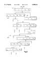
- character segmentationis performed by examining an upper left hand corner of the text region and examining pixels (that have been binarized) to find a white border around a region of black pixels. In order to make sense to a reader the text must consist of dark pixels that make up the character bounded by whitespace of at least a minimal width.
- FIGS. 19A-19Sdepict a sequence of functional tests that are performed on character identified regions.
- the testsare performed on any array of binarized pixels of any width and height (in pixels).
- the character "6"is chosen for uniformity in illustration and the height and width in pixels is chosen to be small to make the illustration easier. In practice a character would be depicted using more than the number of pixels shown in FIGS. 19A-19S.
- FIGS. 19A-19Seach character depiction has been identified with a function.
- the FIG. 19A depictionis identified as functional test f(0) and is assigned a value of 9/6 or 1.5.
- the value 9/6is derived from a scan of the pixel rows that make up the character.
- FIG. 21is a depiction of a tree classifier 530 for digits in the range of 0-9. A similar classification scheme is used for letters of the alphabet.
- a first decision step 532is used to begin a traversal of the tree. This decision is based upon five functional tests that are designated f(0), f(3), f(4), f(14), and f(33).
- the test f(0)(FIG. 19A) is performed by beginning at a right edge of the character occupied region and scanning across each row while keeping track of transitions from white space pixels to black pixels.
- a first transitionoccurs at point between two pixels 542, 544.
- two transitionsoccur, one at an interface between the two pixels 552, 554 and a second between the two pixels 556, 558.
- a sum for the characteris determined. In the illustrated example this sum is ⁇ 9 ⁇ and is calculated from the sum of transitions for the rows that include black pixels.
- a next stepis performed by scanning the character as follows: when scanning lines pass through the boundaries of the character, always assign a one ⁇ 1 ⁇ value regardless of the number of intersections with black pixels that are encountered.
- the result of this second tabulationis the number ⁇ 6 ⁇ and is depicted to the right in FIG. 19A.
- the result for the functional test f(0)is determined as the quotient of these two determinations. Although a small number of pixels are shown for representation purposes, an actual image would include more pixels for the character.
- a similar test to the test of FIG. 19Ais performed for the character depicted in FIGS. 19B, 19C, and 19D except that the scan direction is changed.
- the tests of FIGS. 19F, 19G, and 19Halso involve partitioning and scanning of the character as captured by the imaging.
- test f(10), f(11), f(12) and f(13) depicted in FIG. 19Iinvolve a scanning of partitioned character regions. Instead of transitions, the scanning determines a depth, in pixels from a character boundary before the scan reaches a black pixel.
- Test f(10)is a top half scan from the left
- test f(11)is a bottom half scan from the left
- test f(12)is a top half scan from the right
- test f(13)is a bottom half scan from the left.
- FIG. 19Jdepicts a vertical scan for four tests f(14), f(15), f(16), and f(17). These four tests also monitor the depth into the character to which one must scan before reaching a black pixel. Test f(14) is from the bottom for the left hand side of the character, f(15) is from the bottom for the right hand side of the character, f(16) is from the top for the left hand side and f(17) is for the top and the right hand side.
- FIG. 19Kdepicts the tests for functions f(18) and f(19). This is a scan into the character of the middle third from the left and the right respectively.
- FIG. 19Lis a scan of the middle third from the top to define f(21) and from the bottom to define f(20).
- FIGS. 19M-19Pdefine tests f(22), f(26), f(27), f(30) that are based on the area of the character pixels (in square pixels) as a denominator and the number of black pixels as a numerator.
- the tests in FIGS. 19Q-19Sare tests that are based on the perimeter of the bounding character region and the number of black pixels that define the character within that region.
- a first or root decision step 532contains five functional tests. Two branches based on the first decision step 532 lead to two tree nodes 534, 536 at a second level of the tree.
- the results of the various tests f(0), f(1) . . . for a given footare tabulated in FIGS. 20A-20C for the ten digits 0-9.
- test f(0) for the digit ⁇ 0 ⁇ for this fontis calculated to be 1.81.
- f i [k]where i is the ith test and k is the kth digit. Using this notation f 0 [0] is 1.81.
- the five features or functions found in the first decision step 532are determined. Refer to these tests as f 0 [?], f 3 [?], f 4 [?], f 14 [?], f 33 [?].
- the decision tree at step 532involves the calculation of the summation of differences:
- the descision at the node 532branches in one or two directions based upon the following test:
- dif(1) [node 534] and dif(7) [node 534]can be calculated. If dif(1) ⁇ dif(7), then the unknown input character is a one ⁇ 1 ⁇ since a leaf in the decision tree has been reached. Otherwise the character is a seven ⁇ 7 ⁇ .
- the decision treeis a complete classification system for the digits 0-9.
- the maximum number of nodes that need be traveled for each unknown characteris 8 (to discriminate between a 6 and an 8) and the minimum number of nodes that have to be traversed is two (to discriminate between a 1 and a 7).
Landscapes
- Physics & Mathematics (AREA)
- Electromagnetism (AREA)
- Engineering & Computer Science (AREA)
- Health & Medical Sciences (AREA)
- General Health & Medical Sciences (AREA)
- Toxicology (AREA)
- Artificial Intelligence (AREA)
- Computer Vision & Pattern Recognition (AREA)
- General Physics & Mathematics (AREA)
- Theoretical Computer Science (AREA)
- Image Input (AREA)
Abstract
Description
dif(a,b)=Σabs(m(x)[a,b]-f(x)[?]).
Claims (15)
Priority Applications (1)
| Application Number | Priority Date | Filing Date | Title |
|---|---|---|---|
| US08/949,073US6000612A (en) | 1997-10-10 | 1997-10-10 | Portable data collection device having optical character recognition |
Applications Claiming Priority (1)
| Application Number | Priority Date | Filing Date | Title |
|---|---|---|---|
| US08/949,073US6000612A (en) | 1997-10-10 | 1997-10-10 | Portable data collection device having optical character recognition |
Publications (1)
| Publication Number | Publication Date |
|---|---|
| US6000612Atrue US6000612A (en) | 1999-12-14 |
Family
ID=25488565
Family Applications (1)
| Application Number | Title | Priority Date | Filing Date |
|---|---|---|---|
| US08/949,073Expired - LifetimeUS6000612A (en) | 1997-10-10 | 1997-10-10 | Portable data collection device having optical character recognition |
Country Status (1)
| Country | Link |
|---|---|
| US (1) | US6000612A (en) |
Cited By (88)
| Publication number | Priority date | Publication date | Assignee | Title |
|---|---|---|---|---|
| WO2000065526A1 (en)* | 1999-04-28 | 2000-11-02 | Peripheral Dynamics Inc. | Apparatus and methods for scanning documents including omr, bar-code, and image data |
| WO2002049344A1 (en)* | 2000-12-15 | 2002-06-20 | Leonard Reiffel | Imaged coded data source tracking product |
| EP1223536A1 (en)* | 2001-01-11 | 2002-07-17 | Pace Micro Technology PLC | Data reader and method of use thereof |
| US6457645B1 (en)* | 1999-04-13 | 2002-10-01 | Hewlett-Packard Company | Optical assembly having lens offset from optical axis |
| US20020158136A1 (en)* | 2000-03-04 | 2002-10-31 | Daniel Christopher J | Probe signalling |
| US20020181805A1 (en)* | 1999-06-22 | 2002-12-05 | Loeb Helen S. | Apparatus and methods for image scanning of variable sized documents having variable orientations |
| US6502754B1 (en)* | 1999-03-01 | 2003-01-07 | Symbol Technologies, Inc. | Data acquisition device |
| US20030019934A1 (en)* | 1998-07-08 | 2003-01-30 | Hand Held Products, Inc. | Optical reader aiming assembly comprising aperture |
| US20030034395A1 (en)* | 1999-06-07 | 2003-02-20 | Metrologic Instruments, Inc. | Planar light illumination and imaging (PLIIM) based system having a linear image detection chip mounting assembly with means for preventing misalignment between the field of view (FOV) of said linear image detection chip and the co-planar laser illumination beam (PLIB) produced by said PLIIM based system, in response to thermal expansion and/or contraction within said PLIIM based system |
| US20030085284A1 (en)* | 2000-02-28 | 2003-05-08 | Psc Scanning, Inc. | Multi-format bar code reader |
| US20030102376A1 (en)* | 2001-07-31 | 2003-06-05 | Hand Held Products, Inc. | Image device having indicia-controlled image parsing mode |
| WO2002080520A3 (en)* | 2001-03-30 | 2003-08-07 | Siemens Dematic Postal Automat | Method and system for image processing |
| US20030152293A1 (en)* | 2002-01-24 | 2003-08-14 | Joel Bresler | Method and system for locating position in printed texts and delivering multimedia information |
| US20030184121A1 (en)* | 2002-04-30 | 2003-10-02 | L&L Products, Inc. | Reinforcement system utilizing a hollow carrier |
| US20040041027A1 (en)* | 2000-12-15 | 2004-03-04 | Leonard Reiffel | Imaged coded data source transducer product |
| US20040125224A1 (en)* | 2000-08-18 | 2004-07-01 | Leonard Reiffel | Annotating imaged data product |
| US6832725B2 (en) | 1999-10-04 | 2004-12-21 | Hand Held Products, Inc. | Optical reader comprising multiple color illumination |
| US20050102332A1 (en)* | 2000-12-15 | 2005-05-12 | Leonard Reiffel | Multi-imager multi-source multi-use coded data source data iInput product |
| US6942151B2 (en) | 2001-05-15 | 2005-09-13 | Welch Allyn Data Collection, Inc. | Optical reader having decoding and image capturing functionality |
| US20060027657A1 (en)* | 2004-08-04 | 2006-02-09 | Laurens Ninnink | Method and apparatus for high resolution decoding of encoded symbols |
| US7000840B2 (en) | 2000-05-03 | 2006-02-21 | Leonard Reiffel | Dual mode data imaging product |
| US20060043186A1 (en)* | 2004-08-30 | 2006-03-02 | Nadabar Sateesha G | Methods and apparatus for reading bar code identifications |
| US20060062460A1 (en)* | 2004-08-10 | 2006-03-23 | Fujitsu Limited | Character recognition apparatus and method for recognizing characters in an image |
| US20060082557A1 (en)* | 2000-04-05 | 2006-04-20 | Anoto Ip Lic Hb | Combined detection of position-coding pattern and bar codes |
| US7034803B1 (en) | 2000-08-18 | 2006-04-25 | Leonard Reiffel | Cursor display privacy product |
| US7111787B2 (en) | 2001-05-15 | 2006-09-26 | Hand Held Products, Inc. | Multimode image capturing and decoding optical reader |
| US20060213999A1 (en)* | 2005-03-24 | 2006-09-28 | Wang Ynjiun P | Synthesis decoding and methods of use thereof |
| US7137711B1 (en) | 2000-03-21 | 2006-11-21 | Leonard Reiffel | Multi-user retro reflector data input |
| US7181066B1 (en) | 2002-12-26 | 2007-02-20 | Cognex Technology And Investment Corporation | Method for locating bar codes and symbols in an image |
| US20070187506A1 (en)* | 2001-04-19 | 2007-08-16 | Leonard Reiffel | Combined imaging coded data source data acquisition |
| US7270274B2 (en) | 1999-10-04 | 2007-09-18 | Hand Held Products, Inc. | Imaging module comprising support post for optical reader |
| US7287697B2 (en) | 2001-07-13 | 2007-10-30 | Hand Held Products, Inc. | Optical reader having a color imager |
| US7293712B2 (en) | 2004-10-05 | 2007-11-13 | Hand Held Products, Inc. | System and method to automatically discriminate between a signature and a dataform |
| US20070285698A1 (en)* | 2006-06-09 | 2007-12-13 | Wang Ynjiun P | Indicia reading apparatus having reduced trigger-to-read time |
| US20070290042A1 (en)* | 2004-05-06 | 2007-12-20 | United States Postal Service | Mailing label having a signature section and method of using same |
| US20080004822A1 (en)* | 2006-06-29 | 2008-01-03 | Sateesha Nadabar | Method and Apparatus for Verifying Two Dimensional Mark Quality |
| US7346184B1 (en) | 2000-05-02 | 2008-03-18 | Digimarc Corporation | Processing methods combining multiple frames of image data |
| US7347374B2 (en) | 2003-11-13 | 2008-03-25 | Metrologic Instruments, Inc. | Hand-supportable digital imaging-based bar code symbol reader employing an event-driven system control subsystem, automatic IR-based object detection, and trigger-switch activated image capture and processing subsystem |
| US7357325B2 (en) | 2003-11-13 | 2008-04-15 | Metrologic Instruments, Inc. | Hand-supportable imaging-based bar code symbol reader employing a CMOS-type image sensor using global exposure techniques |
| US20080142602A1 (en)* | 2000-11-24 | 2008-06-19 | Knowles C Harry | Laser illumination beam generation system employing despeckling of the laser beam using high-frequency modulation of the laser diode current and optical multiplexing of the component laser beams |
| US7464877B2 (en) | 2003-11-13 | 2008-12-16 | Metrologic Instruments, Inc. | Digital imaging-based bar code symbol reading system employing image cropping pattern generator and automatic cropped image processor |
| US7500614B2 (en) | 1999-10-04 | 2009-03-10 | Hand Held Products, Inc. | Imaging module for optical reader |
| US7513428B2 (en) | 2001-11-21 | 2009-04-07 | Metrologic Instruments, Inc. | Planar laser illumination and imaging device employing laser current modulation to generate spectral components and reduce temporal coherence of laser beam, so as to achieve a reduction in speckle-pattern noise during time-averaged detection of images of objects illuminated thereby during imaging operations |
| US7516898B2 (en) | 2000-11-24 | 2009-04-14 | Metrologic Instruments, Inc. | Digital image capturing and processing system for producing and projecting a complex of coplanar illumination and imaging planes into a 3D imaging volume and controlling illumination control parameters in said system using the detected motion and velocity of object |
| US7523863B2 (en) | 1999-06-07 | 2009-04-28 | Metrologic Instruments, Inc. | Hand-supportable LED-based planar illumination and imaging system |
| US7527202B2 (en) | 2000-06-07 | 2009-05-05 | Metrologic Instruments, Inc. | Hand-supportable planar linear illumination and imaging (PLIIM) based code symbol reading system |
| US7581681B2 (en) | 1998-03-24 | 2009-09-01 | Metrologic Instruments, Inc. | Tunnel-type digital imaging system for use within retail shopping environments such as supermarkets |
| US7594609B2 (en) | 2003-11-13 | 2009-09-29 | Metrologic Instruments, Inc. | Automatic digital video image capture and processing system supporting image-processing based code symbol reading during a pass-through mode of system operation at a retail point of sale (POS) station |
| US7600689B2 (en) | 1999-06-07 | 2009-10-13 | Metrologic Instruments, Inc. | Tunnel-based object identification and dimensioning system |
| US7607581B2 (en) | 2003-11-13 | 2009-10-27 | Metrologic Instruments, Inc. | Digital imaging-based code symbol reading system permitting modification of system features and functionalities |
| US7637430B2 (en) | 2003-05-12 | 2009-12-29 | Hand Held Products, Inc. | Picture taking optical reader |
| US20100044436A1 (en)* | 2008-08-19 | 2010-02-25 | The Code Corporation | Graphical code readers that provide sequenced illumination for glare reduction |
| US7708205B2 (en) | 2003-11-13 | 2010-05-04 | Metrologic Instruments, Inc. | Digital image capture and processing system employing multi-layer software-based system architecture permitting modification and/or extension of system features and functions by way of third party code plug-ins |
| US20100147948A1 (en)* | 2008-12-12 | 2010-06-17 | George Powell | Graphical code readers that are configured for glare reduction |
| US7784696B2 (en) | 2006-06-09 | 2010-08-31 | Hand Held Products, Inc. | Indicia reading apparatus having image sensing and processing circuit |
| US7841533B2 (en) | 2003-11-13 | 2010-11-30 | Metrologic Instruments, Inc. | Method of capturing and processing digital images of an object within the field of view (FOV) of a hand-supportable digitial image capture and processing system |
| US20100316302A1 (en)* | 2005-09-22 | 2010-12-16 | Google, Inc., A Delaware Corporation | Adaptive Image Maps |
| US7954719B2 (en) | 2000-11-24 | 2011-06-07 | Metrologic Instruments, Inc. | Tunnel-type digital imaging-based self-checkout system for use in retail point-of-sale environments |
| US7963448B2 (en) | 2004-12-22 | 2011-06-21 | Cognex Technology And Investment Corporation | Hand held machine vision method and apparatus |
| US20110214441A1 (en)* | 2010-03-05 | 2011-09-08 | Whirlpool Corporation | Select-fill dispensing system |
| WO2011111079A1 (en)* | 2010-03-11 | 2011-09-15 | Datalogic Scanning Group Sr.L. | Image capturing device |
| US8169478B2 (en) | 2006-12-14 | 2012-05-01 | Cognex Corporation | Method and apparatus for calibrating a mark verifier |
| US20120153022A1 (en)* | 2002-06-04 | 2012-06-21 | Hand Held Products, Inc. | Apparatus operative for capture of image data |
| US20130027573A1 (en)* | 2011-07-26 | 2013-01-31 | Symbol Technologies, Inc. | Method and apparatus for auto-detecting orientation of free-form document using ocr |
| US20130107036A1 (en)* | 2011-10-28 | 2013-05-02 | General Electric Company | Inspection system and method for correlating data from sensors and visual displays |
| US20130134220A1 (en)* | 2011-11-29 | 2013-05-30 | Symbol Technologies, Inc. | Apparatus for and method of uniformly illuminating fields of view in a point-of-transaction workstation |
| US8657200B2 (en) | 2011-06-20 | 2014-02-25 | Metrologic Instruments, Inc. | Indicia reading terminal with color frame processing |
| US8682077B1 (en) | 2000-11-28 | 2014-03-25 | Hand Held Products, Inc. | Method for omnidirectional processing of 2D images including recognizable characters |
| US8873892B2 (en) | 2012-08-21 | 2014-10-28 | Cognex Corporation | Trainable handheld optical character recognition systems and methods |
| US8998090B1 (en) | 2013-03-15 | 2015-04-07 | Cognex Corporation | Standoff for optical imaging system |
| US20160267305A1 (en)* | 2008-12-12 | 2016-09-15 | The Code Corporation | Graphical barcode readers that are configured for glare reduction |
| US9454707B1 (en)* | 2015-10-29 | 2016-09-27 | Roger Tracy | System and method for reading a tire code and obtaining tire-related information |
| US9552506B1 (en) | 2004-12-23 | 2017-01-24 | Cognex Technology And Investment Llc | Method and apparatus for industrial identification mark verification |
| USD779491S1 (en)* | 2014-03-10 | 2017-02-21 | Datalogic Ip Tech S.R.L. | Optical module |
| US20180075269A1 (en)* | 2016-09-15 | 2018-03-15 | Datalogic IP Tech, S.r.l. | Machine-readable symbol reader with distributed illumination and/or image capture |
| US10068153B2 (en) | 2012-08-21 | 2018-09-04 | Cognex Corporation | Trainable handheld optical character recognition systems and methods |
| USD830362S1 (en)* | 2015-05-07 | 2018-10-09 | Datalogic Ip Tech S.R.L. | Barcode reading module |
| US10140741B2 (en) | 2015-12-14 | 2018-11-27 | General Electric Company | Collection and validation of data from visual displays |
| WO2018225100A1 (en)* | 2017-06-07 | 2018-12-13 | Datalogic IP Tech S.r.I. | Data collection systems and methods to capture images of and decode information from machine-readable symbols |
| US10192127B1 (en) | 2017-07-24 | 2019-01-29 | Bank Of America Corporation | System for dynamic optical character recognition tuning |
| US10198647B2 (en) | 2015-09-25 | 2019-02-05 | Datalogic IP Tech, S.r.l. | Compact imaging module with range finder |
| US10210365B2 (en) | 2011-09-30 | 2019-02-19 | Hand Held Products, Inc. | Devices and methods employing dual target auto exposure |
| US10346702B2 (en) | 2017-07-24 | 2019-07-09 | Bank Of America Corporation | Image data capture and conversion |
| US10592715B2 (en) | 2007-11-13 | 2020-03-17 | Cognex Corporation | System and method for reading patterns using multiple image frames |
| CN112183525A (en)* | 2020-09-15 | 2021-01-05 | 中保车服科技服务股份有限公司 | Text recognition model construction method and device and text recognition method and device |
| US11176311B1 (en)* | 2020-07-09 | 2021-11-16 | International Business Machines Corporation | Enhanced section detection using a combination of object detection with heuristics |
| US20220057617A1 (en)* | 2020-08-20 | 2022-02-24 | Carl Zeiss Microscopy Gmbh | System and method for monitoring of states of components of a microscop |
| US20240406424A1 (en)* | 2022-02-17 | 2024-12-05 | Op Solutions Llc | Systems and methods for video coding for machines using an autoencoder |
Citations (47)
| Publication number | Priority date | Publication date | Assignee | Title |
|---|---|---|---|---|
| US4409470A (en)* | 1982-01-25 | 1983-10-11 | Symbol Technologies, Inc. | Narrow-bodied, single-and twin-windowed portable laser scanning head for reading bar code symbols |
| JPS6367692A (en)* | 1986-09-09 | 1988-03-26 | Nippon Denso Co Ltd | Optical information reader |
| JPS6383886A (en)* | 1986-09-29 | 1988-04-14 | Matsushita Electric Ind Co Ltd | Bar code detector |
| US4766300A (en)* | 1984-08-06 | 1988-08-23 | Norand Corporation | Instant portable bar code reader |
| JPH02264383A (en)* | 1989-04-05 | 1990-10-29 | Matsushita Electric Ind Co Ltd | barcode reader |
| US5010580A (en)* | 1989-08-25 | 1991-04-23 | Hewlett-Packard Company | Method and apparatus for extracting information from forms |
| US5019699A (en)* | 1988-08-31 | 1991-05-28 | Norand Corporation | Hand-held optical character reader with means for instantaneously reading information from a predetermined area at an optical sensing area |
| US5038392A (en)* | 1990-02-12 | 1991-08-06 | International Business Machines Corporation | Method and apparatus for adaptive image processing by recognizing a characterizing indicium in a captured image of a document |
| JPH03198175A (en)* | 1989-12-27 | 1991-08-29 | Fujikura Ltd | barcode reader |
| US5077809A (en)* | 1989-05-30 | 1991-12-31 | Farshad Ghazizadeh | Optical character recognition |
| US5080456A (en)* | 1990-02-26 | 1992-01-14 | Symbol Technologies, Inc. | Laser scanners with extended working range |
| US5131053A (en)* | 1988-08-10 | 1992-07-14 | Caere Corporation | Optical character recognition method and apparatus |
| US5130520A (en)* | 1982-01-25 | 1992-07-14 | Symbol Technologies, Inc. | Narrow-bodied, single- and twin-windowed portable laser scanning head for reading bar code symbols |
| US5168149A (en)* | 1989-10-30 | 1992-12-01 | Symbol Technologies, Inc. | Scan pattern generators for bar code symbol readers |
| US5187356A (en)* | 1981-12-28 | 1993-02-16 | Norand Corporation | Instant portable bar code reader |
| US5200597A (en)* | 1991-02-07 | 1993-04-06 | Psc, Inc. | Digitally controlled system for scanning and reading bar codes |
| US5210398A (en)* | 1991-06-14 | 1993-05-11 | Symbol Technologies, Inc. | Optical scanner with extended depth of focus |
| JPH05242287A (en)* | 1992-02-27 | 1993-09-21 | Olympus Optical Co Ltd | Color bar code recording and reproducing device |
| US5258604A (en)* | 1992-01-28 | 1993-11-02 | Psc, Inc. | Bar code scanner |
| US5262871A (en)* | 1989-11-13 | 1993-11-16 | Rutgers, The State University | Multiple resolution image sensor |
| US5278397A (en)* | 1991-07-25 | 1994-01-11 | Symbol Technologies, Inc. | Multi-resolution bar code reader |
| US5296690A (en)* | 1991-03-28 | 1994-03-22 | Omniplanar, Inc. | System for locating and determining the orientation of bar codes in a two-dimensional image |
| US5308966A (en)* | 1986-08-08 | 1994-05-03 | Norand Corporation | Hand-held instant bar code reader having automatic focus control for operation over a range of distances |
| US5309243A (en)* | 1992-06-10 | 1994-05-03 | Eastman Kodak Company | Method and apparatus for extending the dynamic range of an electronic imaging system |
| JPH06129891A (en)* | 1992-10-19 | 1994-05-13 | Sony Corp | Vibration detecting method and apparatus thereof |
| US5314631A (en)* | 1989-10-25 | 1994-05-24 | Fujitsu Limited | Stationary bar code reader which can be detected and separated into a hand-held bar code reader |
| JPH06162247A (en)* | 1992-11-25 | 1994-06-10 | Matsushita Electric Ind Co Ltd | Bar code reader for reading 2D codes |
| US5331143A (en)* | 1992-08-28 | 1994-07-19 | Symbol Technologies, Inc. | Optical scanner using an axicon and an aperture to aspherically form the scanning beam |
| US5340973A (en)* | 1990-09-17 | 1994-08-23 | Metrologic Instruments, Inc. | Automatic laser scanning system and method of reading bar code symbols using same |
| US5349172A (en)* | 1992-02-27 | 1994-09-20 | Alex Roustaei | Optical scanning head |
| US5354977A (en)* | 1992-02-27 | 1994-10-11 | Alex Roustaei | Optical scanning head |
| US5406063A (en)* | 1993-05-07 | 1995-04-11 | Telxon Corporation | Hand-held data scanner having adjustable keyboard panel |
| US5414251A (en)* | 1992-03-12 | 1995-05-09 | Norand Corporation | Reader for decoding two-dimensional optical information |
| US5418357A (en)* | 1992-06-22 | 1995-05-23 | Matsushita Electric Industrial Co., Ltd. | Bar-code reader permitting selective use of a whole or a part of an image sensor |
| US5420943A (en)* | 1992-04-13 | 1995-05-30 | Mak; Stephen M. | Universal computer input device |
| US5468947A (en)* | 1986-08-08 | 1995-11-21 | Norand Corporation | Pocket size data capture unit with processor and shell modules |
| US5478997A (en)* | 1988-10-21 | 1995-12-26 | Symbol Technologies, Inc. | Symbol scanning system and method having adaptive pattern generation |
| US5486688A (en)* | 1991-06-26 | 1996-01-23 | Asahi Kogaku Kogyo Kabushiki Kaisha | Non-scanning type optical reading apparatus having illuminating equalization filter |
| US5496992A (en)* | 1994-06-21 | 1996-03-05 | Lxe, Inc. | Dual trigger multiplexed data entry terminal |
| US5504316A (en)* | 1990-05-08 | 1996-04-02 | Symbol Technologies, Inc. | Laser scanning system and scanning method for reading 1-D and 2-D barcode symbols |
| US5512739A (en)* | 1990-03-28 | 1996-04-30 | Omniplanar, Inc. | Dual processor omnidirectional bar code reader with dual memory for bar code location and orientation |
| US5581635A (en)* | 1995-07-25 | 1996-12-03 | United Parcel Service Of America, Inc. | Method and system for fast rotation of run-length encoded images |
| US5691773A (en)* | 1995-09-12 | 1997-11-25 | Metanetics Corporation | Anti-hand-jittering dataform readers and methods |
| US5703349A (en)* | 1995-06-26 | 1997-12-30 | Metanetics Corporation | Portable data collection device with two dimensional imaging assembly |
| US5714745A (en)* | 1995-12-20 | 1998-02-03 | Metanetics Corporation | Portable data collection device with color imaging assembly |
| US5754684A (en)* | 1994-06-30 | 1998-05-19 | Samsung Electronics Co., Ltd. | Image area discrimination apparatus |
| US5841121A (en)* | 1988-08-31 | 1998-11-24 | Norand Technology Corporation | Hand-held optically readable character set reader having automatic focus control for operation over a range of distances |
- 1997
- 1997-10-10USUS08/949,073patent/US6000612A/ennot_activeExpired - Lifetime
Patent Citations (47)
| Publication number | Priority date | Publication date | Assignee | Title |
|---|---|---|---|---|
| US5187356A (en)* | 1981-12-28 | 1993-02-16 | Norand Corporation | Instant portable bar code reader |
| US4409470A (en)* | 1982-01-25 | 1983-10-11 | Symbol Technologies, Inc. | Narrow-bodied, single-and twin-windowed portable laser scanning head for reading bar code symbols |
| US5130520A (en)* | 1982-01-25 | 1992-07-14 | Symbol Technologies, Inc. | Narrow-bodied, single- and twin-windowed portable laser scanning head for reading bar code symbols |
| US4766300A (en)* | 1984-08-06 | 1988-08-23 | Norand Corporation | Instant portable bar code reader |
| US5468947A (en)* | 1986-08-08 | 1995-11-21 | Norand Corporation | Pocket size data capture unit with processor and shell modules |
| US5308966A (en)* | 1986-08-08 | 1994-05-03 | Norand Corporation | Hand-held instant bar code reader having automatic focus control for operation over a range of distances |
| JPS6367692A (en)* | 1986-09-09 | 1988-03-26 | Nippon Denso Co Ltd | Optical information reader |
| JPS6383886A (en)* | 1986-09-29 | 1988-04-14 | Matsushita Electric Ind Co Ltd | Bar code detector |
| US5131053A (en)* | 1988-08-10 | 1992-07-14 | Caere Corporation | Optical character recognition method and apparatus |
| US5841121A (en)* | 1988-08-31 | 1998-11-24 | Norand Technology Corporation | Hand-held optically readable character set reader having automatic focus control for operation over a range of distances |
| US5019699A (en)* | 1988-08-31 | 1991-05-28 | Norand Corporation | Hand-held optical character reader with means for instantaneously reading information from a predetermined area at an optical sensing area |
| US5478997A (en)* | 1988-10-21 | 1995-12-26 | Symbol Technologies, Inc. | Symbol scanning system and method having adaptive pattern generation |
| JPH02264383A (en)* | 1989-04-05 | 1990-10-29 | Matsushita Electric Ind Co Ltd | barcode reader |
| US5077809A (en)* | 1989-05-30 | 1991-12-31 | Farshad Ghazizadeh | Optical character recognition |
| US5010580A (en)* | 1989-08-25 | 1991-04-23 | Hewlett-Packard Company | Method and apparatus for extracting information from forms |
| US5314631A (en)* | 1989-10-25 | 1994-05-24 | Fujitsu Limited | Stationary bar code reader which can be detected and separated into a hand-held bar code reader |
| US5168149A (en)* | 1989-10-30 | 1992-12-01 | Symbol Technologies, Inc. | Scan pattern generators for bar code symbol readers |
| US5262871A (en)* | 1989-11-13 | 1993-11-16 | Rutgers, The State University | Multiple resolution image sensor |
| JPH03198175A (en)* | 1989-12-27 | 1991-08-29 | Fujikura Ltd | barcode reader |
| US5038392A (en)* | 1990-02-12 | 1991-08-06 | International Business Machines Corporation | Method and apparatus for adaptive image processing by recognizing a characterizing indicium in a captured image of a document |
| US5080456A (en)* | 1990-02-26 | 1992-01-14 | Symbol Technologies, Inc. | Laser scanners with extended working range |
| US5512739A (en)* | 1990-03-28 | 1996-04-30 | Omniplanar, Inc. | Dual processor omnidirectional bar code reader with dual memory for bar code location and orientation |
| US5504316A (en)* | 1990-05-08 | 1996-04-02 | Symbol Technologies, Inc. | Laser scanning system and scanning method for reading 1-D and 2-D barcode symbols |
| US5340973A (en)* | 1990-09-17 | 1994-08-23 | Metrologic Instruments, Inc. | Automatic laser scanning system and method of reading bar code symbols using same |
| US5200597A (en)* | 1991-02-07 | 1993-04-06 | Psc, Inc. | Digitally controlled system for scanning and reading bar codes |
| US5296690A (en)* | 1991-03-28 | 1994-03-22 | Omniplanar, Inc. | System for locating and determining the orientation of bar codes in a two-dimensional image |
| US5210398A (en)* | 1991-06-14 | 1993-05-11 | Symbol Technologies, Inc. | Optical scanner with extended depth of focus |
| US5486688A (en)* | 1991-06-26 | 1996-01-23 | Asahi Kogaku Kogyo Kabushiki Kaisha | Non-scanning type optical reading apparatus having illuminating equalization filter |
| US5278397A (en)* | 1991-07-25 | 1994-01-11 | Symbol Technologies, Inc. | Multi-resolution bar code reader |
| US5258604A (en)* | 1992-01-28 | 1993-11-02 | Psc, Inc. | Bar code scanner |
| JPH05242287A (en)* | 1992-02-27 | 1993-09-21 | Olympus Optical Co Ltd | Color bar code recording and reproducing device |
| US5349172A (en)* | 1992-02-27 | 1994-09-20 | Alex Roustaei | Optical scanning head |
| US5354977A (en)* | 1992-02-27 | 1994-10-11 | Alex Roustaei | Optical scanning head |
| US5414251A (en)* | 1992-03-12 | 1995-05-09 | Norand Corporation | Reader for decoding two-dimensional optical information |
| US5420943A (en)* | 1992-04-13 | 1995-05-30 | Mak; Stephen M. | Universal computer input device |
| US5309243A (en)* | 1992-06-10 | 1994-05-03 | Eastman Kodak Company | Method and apparatus for extending the dynamic range of an electronic imaging system |
| US5418357A (en)* | 1992-06-22 | 1995-05-23 | Matsushita Electric Industrial Co., Ltd. | Bar-code reader permitting selective use of a whole or a part of an image sensor |
| US5331143A (en)* | 1992-08-28 | 1994-07-19 | Symbol Technologies, Inc. | Optical scanner using an axicon and an aperture to aspherically form the scanning beam |
| JPH06129891A (en)* | 1992-10-19 | 1994-05-13 | Sony Corp | Vibration detecting method and apparatus thereof |
| JPH06162247A (en)* | 1992-11-25 | 1994-06-10 | Matsushita Electric Ind Co Ltd | Bar code reader for reading 2D codes |
| US5406063A (en)* | 1993-05-07 | 1995-04-11 | Telxon Corporation | Hand-held data scanner having adjustable keyboard panel |
| US5496992A (en)* | 1994-06-21 | 1996-03-05 | Lxe, Inc. | Dual trigger multiplexed data entry terminal |
| US5754684A (en)* | 1994-06-30 | 1998-05-19 | Samsung Electronics Co., Ltd. | Image area discrimination apparatus |
| US5703349A (en)* | 1995-06-26 | 1997-12-30 | Metanetics Corporation | Portable data collection device with two dimensional imaging assembly |
| US5581635A (en)* | 1995-07-25 | 1996-12-03 | United Parcel Service Of America, Inc. | Method and system for fast rotation of run-length encoded images |
| US5691773A (en)* | 1995-09-12 | 1997-11-25 | Metanetics Corporation | Anti-hand-jittering dataform readers and methods |
| US5714745A (en)* | 1995-12-20 | 1998-02-03 | Metanetics Corporation | Portable data collection device with color imaging assembly |
Cited By (286)
| Publication number | Priority date | Publication date | Assignee | Title |
|---|---|---|---|---|
| US7523866B2 (en) | 1997-10-17 | 2009-04-28 | Hand Held Products, Inc. | Bar code reading device having image processing mode |
| US7841532B2 (en) | 1997-10-17 | 2010-11-30 | Hand Held Products, Inc. | Bar code reading device having image processing mode |
| US8282006B2 (en) | 1997-10-17 | 2012-10-09 | Hand Held Products, Inc. | Imaging device operative for image processing |
| US7222789B2 (en) | 1997-10-17 | 2007-05-29 | Hand Held Products, Inc. | Bar code reading device having image processing mode |
| US7527200B2 (en) | 1998-03-24 | 2009-05-05 | Metrologic Instruments, Inc. | Planar laser illumination and imaging (PLIIM) systems with integrated despeckling mechanisms provided therein |
| US7581681B2 (en) | 1998-03-24 | 2009-09-01 | Metrologic Instruments, Inc. | Tunnel-type digital imaging system for use within retail shopping environments such as supermarkets |
| US7584893B2 (en) | 1998-03-24 | 2009-09-08 | Metrologic Instruments, Inc. | Tunnel-type digital imaging system for use within retail shopping environments such as supermarkets |
| US7832643B2 (en) | 1998-03-24 | 2010-11-16 | Metrologic Instruments, Inc. | Hand-supported planar laser illumination and imaging (PLIIM) based systems with laser despeckling mechanisms integrated therein |
| US7673803B2 (en) | 1998-03-24 | 2010-03-09 | Metrologic Instruments, Inc. | Planar laser illumination and imaging (PLIIM) based engine |
| US20030019934A1 (en)* | 1998-07-08 | 2003-01-30 | Hand Held Products, Inc. | Optical reader aiming assembly comprising aperture |
| US6502754B1 (en)* | 1999-03-01 | 2003-01-07 | Symbol Technologies, Inc. | Data acquisition device |
| US6457645B1 (en)* | 1999-04-13 | 2002-10-01 | Hewlett-Packard Company | Optical assembly having lens offset from optical axis |
| US6357658B1 (en) | 1999-04-28 | 2002-03-19 | Peripheral Dynamics, Inc. | Apparatus and methods for scanning documents including OMR, bar-code, and image data |
| WO2000065526A1 (en)* | 1999-04-28 | 2000-11-02 | Peripheral Dynamics Inc. | Apparatus and methods for scanning documents including omr, bar-code, and image data |
| US6978935B2 (en)* | 1999-06-07 | 2005-12-27 | Metrologic Instruments, Inc. | Planar light illumination and imaging (pliim) based system having a linear image detection chip mounting assembly with means for preventing misalignment between the field of view (fov) of said linear image detection chip and the co-planar laser illumination beam (plib) produced by said pliim based system, in response to thermal expansion and/or contraction within said pliim based system |
| US7533821B2 (en) | 1999-06-07 | 2009-05-19 | Metrologic Instruments, Inc. | Hand-supportable planar laser illumination and imaging (PLIIM) device for producing a planar laser illumination beam (PLIB) coplanar with the field of view (FOV) of a linear image detection array |
| US7523863B2 (en) | 1999-06-07 | 2009-04-28 | Metrologic Instruments, Inc. | Hand-supportable LED-based planar illumination and imaging system |
| US20030034395A1 (en)* | 1999-06-07 | 2003-02-20 | Metrologic Instruments, Inc. | Planar light illumination and imaging (PLIIM) based system having a linear image detection chip mounting assembly with means for preventing misalignment between the field of view (FOV) of said linear image detection chip and the co-planar laser illumination beam (PLIB) produced by said PLIIM based system, in response to thermal expansion and/or contraction within said PLIIM based system |
| US7644866B2 (en) | 1999-06-07 | 2010-01-12 | Metrologic Instruments, Inc. | Hand-supportable code symbol reader employing coplanar laser illumination and linear imaging |
| US7621455B2 (en) | 1999-06-07 | 2009-11-24 | Metrologic Instruments, Inc. | Hand-supportable code symbol reader employing coplanar laser illumination and linear imaging |
| US7600689B2 (en) | 1999-06-07 | 2009-10-13 | Metrologic Instruments, Inc. | Tunnel-based object identification and dimensioning system |
| US20020181805A1 (en)* | 1999-06-22 | 2002-12-05 | Loeb Helen S. | Apparatus and methods for image scanning of variable sized documents having variable orientations |
| US7533824B2 (en) | 1999-10-04 | 2009-05-19 | Hand Held Products, Inc. | Image sensor based optical reader |
| US6832725B2 (en) | 1999-10-04 | 2004-12-21 | Hand Held Products, Inc. | Optical reader comprising multiple color illumination |
| US8474722B2 (en) | 1999-10-04 | 2013-07-02 | Hand Held Products, Inc. | Image sensor based optical reader |
| US7270274B2 (en) | 1999-10-04 | 2007-09-18 | Hand Held Products, Inc. | Imaging module comprising support post for optical reader |
| US7878403B2 (en) | 1999-10-04 | 2011-02-01 | Hand Held Products, Inc. | Image sensor based optical reader |
| US9076054B2 (en) | 1999-10-04 | 2015-07-07 | Hand Held Products, Inc. | Image sensor based optical reader |
| US7500614B2 (en) | 1999-10-04 | 2009-03-10 | Hand Held Products, Inc. | Imaging module for optical reader |
| US20030085284A1 (en)* | 2000-02-28 | 2003-05-08 | Psc Scanning, Inc. | Multi-format bar code reader |
| US20070001014A1 (en)* | 2000-02-28 | 2007-01-04 | Psc Scanning, Inc. | Multi-format bar code reader |
| US7527203B2 (en) | 2000-02-28 | 2009-05-05 | Datalogic Scanning, Inc. | Multi-format bar code reader |
| US7137555B2 (en)* | 2000-02-28 | 2006-11-21 | Psc Scanning, Inc. | Multi-format bar code reader |
| US7246747B2 (en) | 2000-02-28 | 2007-07-24 | Datalogic Scanning, Inc. | Multi-format bar code reader |
| US20080011856A1 (en)* | 2000-02-28 | 2008-01-17 | Datalogic Scanning, Inc. | Multi-format bar code reader |
| US20020158136A1 (en)* | 2000-03-04 | 2002-10-31 | Daniel Christopher J | Probe signalling |
| US7441707B2 (en) | 2000-03-04 | 2008-10-28 | Renishaw Plc | Probe signalling |
| US20090130987A1 (en)* | 2000-03-04 | 2009-05-21 | Renishaw Plc | Probe signalling |
| US6776344B2 (en)* | 2000-03-04 | 2004-08-17 | Renishaw Plc | Probe signalling |
| US20040219886A1 (en)* | 2000-03-04 | 2004-11-04 | Renishaw Plc | Probe signalling |
| US7137711B1 (en) | 2000-03-21 | 2006-11-21 | Leonard Reiffel | Multi-user retro reflector data input |
| US20060082557A1 (en)* | 2000-04-05 | 2006-04-20 | Anoto Ip Lic Hb | Combined detection of position-coding pattern and bar codes |
| US8126272B2 (en) | 2000-05-02 | 2012-02-28 | Digimarc Corporation | Methods combining multiple frames of image data |
| US7346184B1 (en) | 2000-05-02 | 2008-03-18 | Digimarc Corporation | Processing methods combining multiple frames of image data |
| US7000840B2 (en) | 2000-05-03 | 2006-02-21 | Leonard Reiffel | Dual mode data imaging product |
| US7527202B2 (en) | 2000-06-07 | 2009-05-05 | Metrologic Instruments, Inc. | Hand-supportable planar linear illumination and imaging (PLIIM) based code symbol reading system |
| US7161581B2 (en) | 2000-08-18 | 2007-01-09 | Leonard Reiffel | Annotating imaged data product |
| US20040125224A1 (en)* | 2000-08-18 | 2004-07-01 | Leonard Reiffel | Annotating imaged data product |
| US7034803B1 (en) | 2000-08-18 | 2006-04-25 | Leonard Reiffel | Cursor display privacy product |
| US7775436B2 (en) | 2000-11-24 | 2010-08-17 | Metrologic Instruments, Inc. | Method of driving a plurality of visible and invisible LEDs so as to produce an illumination beam having a dynamically managed ratio of visible to invisible (IR) spectral energy/power during object illumination and imaging operations |
| US7578442B2 (en) | 2000-11-24 | 2009-08-25 | Metrologic Instruments, Inc. | Method of and apparatus for identifying consumer products in a retail environment when bar code symbols on the products are not readable or have been removed from packaging |
| US7658330B2 (en) | 2000-11-24 | 2010-02-09 | Metrologic Instruments, Inc. | Automatic POS-based digital image capturing and processing system employing object motion controlled area-type illumination and imaging operations |
| US7661597B2 (en) | 2000-11-24 | 2010-02-16 | Metrologic Instruments, Inc. | Coplanar laser illumination and imaging subsystem employing spectral-mixing and despeckling of laser illumination |
| US7661595B2 (en) | 2000-11-24 | 2010-02-16 | Metrologic Instruments, Inc. | Digital image capturing and processing system employing a plurality of area-type illuminating and imaging stations projecting a plurality of coextensive area-type illumination and imaging zones into a 3D imaging volume, and controlling operations therewithin using |
| US7614560B2 (en) | 2000-11-24 | 2009-11-10 | Metrologic Instruments, Inc. | Method of illuminating objects at a point of sale (POS) station by adaptively controlling the spectral composition of the wide-area illumination beam produced from an illumination subsystem within an automatic digital image capture and processing system |
| US7665665B2 (en) | 2000-11-24 | 2010-02-23 | Metrologic Instruments, Inc. | Digital illumination and imaging subsystem employing despeckling mechanism employing high-frequency modulation of laser diode drive current and optical beam multiplexing techniques |
| US7611062B2 (en) | 2000-11-24 | 2009-11-03 | Metrologic Instruments, Inc. | Omni-directional digital image capturing and processing system employing coplanar illumination and imaging planes and area-type illumination and imaging zones with the horizontal and vertical sections of the system housing |
| US20080142602A1 (en)* | 2000-11-24 | 2008-06-19 | Knowles C Harry | Laser illumination beam generation system employing despeckling of the laser beam using high-frequency modulation of the laser diode current and optical multiplexing of the component laser beams |
| US7673802B2 (en) | 2000-11-24 | 2010-03-09 | Metrologic Instruments, Inc. | Automatic POS-based digital image capturing and processing system employing a plurality of area-type illumination and imaging zones intersecting within the 3D imaging volume of the system |
| US7594608B2 (en) | 2000-11-24 | 2009-09-29 | Metrologic Instruments, Inc. | Automatic omnidirectional bar code symbol reading system employing linear-type and area-type bar code symbol reading stations within the system housing |
| US8172141B2 (en) | 2000-11-24 | 2012-05-08 | Metrologic Instruments, Inc. | Laser beam despeckling devices |
| US7588188B2 (en) | 2000-11-24 | 2009-09-15 | Metrologic Instruments, Inc. | Pos-based digital image capturing and processing system using automatic object detection, spectral-mixing based illumination and linear imaging techniques |
| US7584892B2 (en) | 2000-11-24 | 2009-09-08 | Metrologic Instruments, Inc. | Digital-imaging based code symbol reading system employing a plurality of coplanar illumination and imaging subsystems, each having a local object motion detection subsystem for automatic detecting objects within the 3D imaging volume, and a local control subsystem for transmitting object detection state data to a global control subsystem for managing the state of operation of said coplanar illumination and imaging subsystems |
| US7581680B2 (en) | 2000-11-24 | 2009-09-01 | Metrologic Instruments, Inc. | Omni-directional digital image capturing and processing system employing coplanar illumination and imaging stations in horizontal and vertical housing sections of the system |
| US8042740B2 (en) | 2000-11-24 | 2011-10-25 | Metrologic Instruments, Inc. | Method of reading bar code symbols on objects at a point-of-sale station by passing said objects through a complex of stationary coplanar illumination and imaging planes projected into a 3D imaging volume |
| US7954719B2 (en) | 2000-11-24 | 2011-06-07 | Metrologic Instruments, Inc. | Tunnel-type digital imaging-based self-checkout system for use in retail point-of-sale environments |
| US7905413B2 (en) | 2000-11-24 | 2011-03-15 | Metrologic Instruments, Inc. | Digital image capturing and processing system employing a plurality of coplanar illumination and imaging subsystems for digitally imaging objects in a 3D imaging volume, and a globally-deployed object motion detection subsystem for automatically detecting and analyzing the motion of objects passing through said 3-D imaging volume |
| US7578445B2 (en) | 2000-11-24 | 2009-08-25 | Metrologic Instruments, Inc. | Automatic POS-based digital image capturing and processing system employing object motion controlled area-type illumination and imaging operations |
| US7878407B2 (en) | 2000-11-24 | 2011-02-01 | Metrologic Instruments, Inc. | POS-based digital image capturing and processing system employing automatic object motion detection and spectral-mixing based illumination techniques |
| US7575169B2 (en) | 2000-11-24 | 2009-08-18 | Metrologic Instruments, Inc. | Digital image capturing and processing system for producing and projecting a plurality of coextensive area-type illumination and imaging zones into a 3D imaging volume and controlling illumination control parameters in said system using the detected motion of objects present therewithin |
| US7575170B2 (en) | 2000-11-24 | 2009-08-18 | Metrologic Instruments, Inc. | POS-based digital image capturing and processing system using automatic object detection, spectral-mixing based illumination and linear imaging techniques |
| US7731091B2 (en) | 2000-11-24 | 2010-06-08 | Metrologic Instruments, Inc. | Digital image capturing and processing system employing automatic object detection and spectral-mixing based illumination techniques |
| US7819326B2 (en) | 2000-11-24 | 2010-10-26 | Metrologic Instruments, Inc. | Network of digital image capturing systems installed at retail POS-based stations and serviced by a remote image processing server in communication therewith |
| US7815113B2 (en) | 2000-11-24 | 2010-10-19 | Metrologic Instruments, Inc. | Method of and system for returning a consumer product in a retail environment so as to prevent or reduce employee theft, as well as provide greater accountability for returned merchandise in retail store environments |
| US7806335B2 (en) | 2000-11-24 | 2010-10-05 | Metrologic Instruments, Inc. | Digital image capturing and processing system for automatically recognizing objects in a POS environment |
| US7571858B2 (en) | 2000-11-24 | 2009-08-11 | Metrologic Instruemtns, Inc. | POS-based digital image capturing and processing system using automatic object detection, spectral-mixing based illumination and linear imaging techniques |
| US7516898B2 (en) | 2000-11-24 | 2009-04-14 | Metrologic Instruments, Inc. | Digital image capturing and processing system for producing and projecting a complex of coplanar illumination and imaging planes into a 3D imaging volume and controlling illumination control parameters in said system using the detected motion and velocity of object |
| US7520433B2 (en) | 2000-11-24 | 2009-04-21 | Metrologic Instruments, Inc. | Method for intelligently controlling the illumination and imagine of objects as they are moved through the 3D imaging volume of a digital image capturing and processing system |
| US7571859B2 (en) | 2000-11-24 | 2009-08-11 | Metrologic Instruments, Inc. | Digital-imaging based code symbol reading system employing a plurality of coplanar illumination and imaging subsystems, global object motion detection subsystem for automatically detecting objects within its 3D imaging volume, and global control subsystem for managing the state of operation of said coplanar illumination and imaging substems |
| US7762465B2 (en) | 2000-11-24 | 2010-07-27 | Metrologic Instruments, Inc. | Device for optically multiplexing a laser beam |
| US7527204B2 (en) | 2000-11-24 | 2009-05-05 | Metrologic Instruments, Inc. | Omni-directional digital image capturing and processing system comprising coplanar illumination and imaging stations automatically detecting object motion and velocity and adjusting exposure and/or illumination control parameters therewithin |
| US7568626B2 (en) | 2000-11-24 | 2009-08-04 | Metrologic Instruments, Inc. | Automatic POS-based digital image capturing and processing system employing a plurality of area-type illumination and imaging zones intersecting within the 3D imaging volume of the system |
| US7770796B2 (en) | 2000-11-24 | 2010-08-10 | Metrologic Instruments, Inc. | Device for producing a laser beam of reduced coherency using high-frequency modulation of the laser diode current and optical multiplexing of the output laser beam |
| US7559474B2 (en) | 2000-11-24 | 2009-07-14 | Metrologic Instruments, Inc. | Automatic omnidirectional bar code symbol reading system employing linear-type and area-type bar code symbol reading stations within the system housing |
| US7806336B2 (en) | 2000-11-24 | 2010-10-05 | Metrologic Instruments, Inc. | Laser beam generation system employing a laser diode and high-frequency modulation circuitry mounted on a flexible circuit |
| US7530497B2 (en) | 2000-11-24 | 2009-05-12 | Metrologic Instruments, Inc. | Digital image capturing and processing system employing an image capturing and processing module and an integrated electronic weigh scale module having a load cell centrally located with respect to said image capturing and processing module |
| US7533823B2 (en) | 2000-11-24 | 2009-05-19 | Metrologic Instruments, Inc. | Digital image capturing and processing system employing a plurality of coplanar illuminating and imaging stations projecting a plurality of coplanar illumination and imaging planes into a 3D imaging volume, and controlling operations therewithin using control data derived from motion data collected from the automated detection of objects passing through said 3D imaging volume |
| US7556199B2 (en) | 2000-11-24 | 2009-07-07 | Metrologic Instruments, Inc. | Digital image capturing and processing system employing a plurality of coplanar illuminating and imaging stations projecting a complex of coplanar illumination and imaging planes into a 3D imaging volume so as to support pass-through and presentation modes of digital imaging at a point of sale (POS) environment |
| US7651028B2 (en) | 2000-11-24 | 2010-01-26 | Metrologic Instruments, Inc. | Intelligent system for automatically recognizing objects at a point of sale (POS) station by omni-directional imaging of the objects using a complex of coplanar illumination and imaging subsystems |
| US7533820B2 (en) | 2000-11-24 | 2009-05-19 | Metrologic Instruments, Inc. | Digital image capturing and processing system employing coplanar illumination and imaging stations which generate coplanar illumination and imaging planes only when and where an object is being moved within the 3D imaging volume |
| US7546952B2 (en) | 2000-11-24 | 2009-06-16 | Metrologic Instruments, Inc. | Method of illuminating objects during digital image capture operations by mixing visible and invisible spectral illumination energy at point of sale (POS) environments |
| US7537165B2 (en) | 2000-11-24 | 2009-05-26 | Metrologic Instruments, Inc. | Omni-directional digital image capturing and processing system employing coplanar illumination and imaging planes and area-type illumination and imaging zones within the system housing |
| US7793841B2 (en) | 2000-11-24 | 2010-09-14 | Metrologic Instruments, Inc. | Laser illumination beam generation system employing despeckling of the laser beam using high-frequency modulation of the laser diode current and optical multiplexing of the component laser beams |
| US7540424B2 (en) | 2000-11-24 | 2009-06-02 | Metrologic Instruments, Inc. | Compact bar code symbol reading system employing a complex of coplanar illumination and imaging stations for omni-directional imaging of objects within a 3D imaging volume |
| US7540422B2 (en) | 2000-11-24 | 2009-06-02 | Metrologic Instruments, Inc. | Digital image capturing and processing system employing imaging window protection plate having an aperture pattern and being disposed over said imaging window and beneath which resides a plurality of coplanar illumination and imaging stations |
| US7784695B2 (en) | 2000-11-24 | 2010-08-31 | Metrologic Instruments, Inc. | Planar laser illumination module (PLIM) employing high-frequency modulation (HFM) of the laser drive currents and optical multplexing of the output laser beams |
| US7543749B2 (en) | 2000-11-24 | 2009-06-09 | Metrologic Instruments, Inc. | Digital image capturing and processing system having a plurality of coplanar illumination and imaging subsystems, each employing a dual-type coplanar linear illumination and imaging engine that supports image-processing based object motion and velocity detection, and automatic image formation and detection along the coplanar illumination and imaging plane produced thereby |
| US8682077B1 (en) | 2000-11-28 | 2014-03-25 | Hand Held Products, Inc. | Method for omnidirectional processing of 2D images including recognizable characters |
| US20040027455A1 (en)* | 2000-12-15 | 2004-02-12 | Leonard Reiffel | Imaged coded data source tracking product |
| US20040041027A1 (en)* | 2000-12-15 | 2004-03-04 | Leonard Reiffel | Imaged coded data source transducer product |
| WO2002049344A1 (en)* | 2000-12-15 | 2002-06-20 | Leonard Reiffel | Imaged coded data source tracking product |
| US6945460B2 (en) | 2000-12-15 | 2005-09-20 | Leonard Reiffel | Imaged coded data source transducer product |
| US7184075B2 (en) | 2000-12-15 | 2007-02-27 | Leonard Reiffel | Imaged coded data source tracking product |
| US7099070B2 (en) | 2000-12-15 | 2006-08-29 | Leonard Reiffel | Multi-imager multi-source multi-use coded data source data input product |
| US20050102332A1 (en)* | 2000-12-15 | 2005-05-12 | Leonard Reiffel | Multi-imager multi-source multi-use coded data source data iInput product |
| EP1223536A1 (en)* | 2001-01-11 | 2002-07-17 | Pace Micro Technology PLC | Data reader and method of use thereof |
| WO2002080520A3 (en)* | 2001-03-30 | 2003-08-07 | Siemens Dematic Postal Automat | Method and system for image processing |
| US7377438B2 (en) | 2001-04-19 | 2008-05-27 | Leonard Reiffel | Combined imaging coded data source data acquisition |
| US20070187506A1 (en)* | 2001-04-19 | 2007-08-16 | Leonard Reiffel | Combined imaging coded data source data acquisition |
| US8794522B2 (en) | 2001-05-15 | 2014-08-05 | Hand Held Products, Inc. | Image capture apparatus and method |
| US7111787B2 (en) | 2001-05-15 | 2006-09-26 | Hand Held Products, Inc. | Multimode image capturing and decoding optical reader |
| US6942151B2 (en) | 2001-05-15 | 2005-09-13 | Welch Allyn Data Collection, Inc. | Optical reader having decoding and image capturing functionality |
| US8439262B2 (en) | 2001-05-15 | 2013-05-14 | Hand Held Products, Inc. | Image capture apparatus and method |
| US7543747B2 (en) | 2001-05-15 | 2009-06-09 | Hand Held Products, Inc. | Image capture apparatus and method |
| US8528818B2 (en) | 2001-07-13 | 2013-09-10 | Hand Held Products, Inc. | Optical reader having an imager |
| US7686222B2 (en) | 2001-07-13 | 2010-03-30 | Hand Held Products, Inc. | Optical reader having a color imager |
| US7287697B2 (en) | 2001-07-13 | 2007-10-30 | Hand Held Products, Inc. | Optical reader having a color imager |
| US8292180B2 (en) | 2001-07-13 | 2012-10-23 | Hand Held Products, Inc. | Optical reader having an imager |
| US7413127B2 (en) | 2001-07-13 | 2008-08-19 | Hand Held Products, Inc. | Optical reader for classifying an image |
| US20030102376A1 (en)* | 2001-07-31 | 2003-06-05 | Hand Held Products, Inc. | Image device having indicia-controlled image parsing mode |
| US7513428B2 (en) | 2001-11-21 | 2009-04-07 | Metrologic Instruments, Inc. | Planar laser illumination and imaging device employing laser current modulation to generate spectral components and reduce temporal coherence of laser beam, so as to achieve a reduction in speckle-pattern noise during time-averaged detection of images of objects illuminated thereby during imaging operations |
| US20030152293A1 (en)* | 2002-01-24 | 2003-08-14 | Joel Bresler | Method and system for locating position in printed texts and delivering multimedia information |
| US7239747B2 (en)* | 2002-01-24 | 2007-07-03 | Chatterbox Systems, Inc. | Method and system for locating position in printed texts and delivering multimedia information |
| US20030184121A1 (en)* | 2002-04-30 | 2003-10-02 | L&L Products, Inc. | Reinforcement system utilizing a hollow carrier |
| US7077460B2 (en) | 2002-04-30 | 2006-07-18 | L&L Products, Inc. | Reinforcement system utilizing a hollow carrier |
| US20120153022A1 (en)* | 2002-06-04 | 2012-06-21 | Hand Held Products, Inc. | Apparatus operative for capture of image data |
| US9224023B2 (en) | 2002-06-04 | 2015-12-29 | Hand Held Products, Inc. | Apparatus operative for capture of image data |
| US8596542B2 (en)* | 2002-06-04 | 2013-12-03 | Hand Held Products, Inc. | Apparatus operative for capture of image data |
| US7181066B1 (en) | 2002-12-26 | 2007-02-20 | Cognex Technology And Investment Corporation | Method for locating bar codes and symbols in an image |
| US8789758B2 (en) | 2003-05-12 | 2014-07-29 | Hand Held Products, Inc. | Picture taking reading apparatus |
| US7637430B2 (en) | 2003-05-12 | 2009-12-29 | Hand Held Products, Inc. | Picture taking optical reader |
| US8104686B2 (en) | 2003-05-12 | 2012-01-31 | Hand Held Products, Inc. | Apparatus comprising image sensor |
| US7681799B2 (en) | 2003-11-13 | 2010-03-23 | Metrologic Instruments, Inc. | Method of reading code symbols using a digital image capturing and processing system employing a micro-computing platform with an event-driven multi-tier software architecture |
| US7347374B2 (en) | 2003-11-13 | 2008-03-25 | Metrologic Instruments, Inc. | Hand-supportable digital imaging-based bar code symbol reader employing an event-driven system control subsystem, automatic IR-based object detection, and trigger-switch activated image capture and processing subsystem |
| US7637433B1 (en) | 2003-11-13 | 2009-12-29 | Metrologic Instruments, Inc. | Digital image capture and processing system employing a micro-computing platform with an event-driven multi-tier modular software architecture and supporting an image-processing based illumination metering program for automatically adjusting illumination during object illumination and imaging operations |
| US7637432B2 (en) | 2003-11-13 | 2009-12-29 | Metrologic Instruments, Inc. | Automatic point-of-sale based code symbol reading system employing automatic object motion detection and illumination control, and digital video image capturing and processing techniques |
| US7624926B2 (en) | 2003-11-13 | 2009-12-01 | Metrologic Instruments, Inc. | Method of automatically reading code symbols on objects present within the field of view (FOV) of a hand-supportable digital-imaging based code symbol reader, by simultaneously projecting an image cropping zone (ICZ) framing pattern and a field of illumination within the FOV during object illumination and imaging operations |
| US7611064B2 (en) | 2003-11-13 | 2009-11-03 | Metrologic Instruments, Inc. | Digital image capture and processing system having automatic illumination measurement and control capabilities realized using a photodetector operating independently of the image sensing array, and an image-processing based illumination metering program for automatically adjusting the illumination duration of the system during object illumination and imaging operations |
| US9785811B2 (en) | 2003-11-13 | 2017-10-10 | Metrologic Instruments, Inc. | Image capture and processing system supporting a multi-tier modular software architecture |
| US7607581B2 (en) | 2003-11-13 | 2009-10-27 | Metrologic Instruments, Inc. | Digital imaging-based code symbol reading system permitting modification of system features and functionalities |
| US7604175B2 (en) | 2003-11-13 | 2009-10-20 | Metrologic Instruments, Inc. | Method of reading bar code symbols using a digital-imaging based code symbol reading system employing an event-driven multi-tier modular software architecture and supporting automatic operating system login and loading of bar code symbol reading application |
| US7594609B2 (en) | 2003-11-13 | 2009-09-29 | Metrologic Instruments, Inc. | Automatic digital video image capture and processing system supporting image-processing based code symbol reading during a pass-through mode of system operation at a retail point of sale (POS) station |
| US7588190B2 (en) | 2003-11-13 | 2009-09-15 | Metrologic Instruments, Inc. | Digital-imaging code symbol reading system supporting automatic programming of system parameters for automatic configuration of said system in hands-on and hands-free modes of operation |
| US7708205B2 (en) | 2003-11-13 | 2010-05-04 | Metrologic Instruments, Inc. | Digital image capture and processing system employing multi-layer software-based system architecture permitting modification and/or extension of system features and functions by way of third party code plug-ins |
| US7712666B2 (en) | 2003-11-13 | 2010-05-11 | Metrologic Instruments, Inc. | Automatically-triggered digital video-imaging based code symbol reading system supporting dynamically controlled object illumination and digital video-imaging operations |
| US7575167B2 (en) | 2003-11-13 | 2009-08-18 | Metrologic Instruments, Inc. | Method of dynamically managing system control parameters in a digital image capture and processing system |
| US7735737B2 (en) | 2003-11-13 | 2010-06-15 | Metrologic Instruments, Inc. | Automatically-triggered digital video-imaging based code symbol reading system supporting ambient illumination mode automatically selected by adaptive control process |
| US9355288B2 (en) | 2003-11-13 | 2016-05-31 | Metrologic Instruments, Inc. | Image capture and processing system supporting a multi-tier modular software architecture |
| US9104930B2 (en) | 2003-11-13 | 2015-08-11 | Metrologic Instruments, Inc. | Code symbol reading system |
| US7568625B2 (en) | 2003-11-13 | 2009-08-04 | Metpologic Instruments, Inc. | Hand-supportable digital image-processing based bar code symbol reading system employing image cropping zone (ICZ) framing and post-image capture cropping |
| US7770798B2 (en) | 2003-11-13 | 2010-08-10 | Metrologic Instruments, Inc. | Automatically-triggered digital video-imaging based code symbol reading system for use in a point-of-sale (POS) environment |
| US7559475B2 (en) | 2003-11-13 | 2009-07-14 | Metrologic Instruments, Inc. | Automatic digital-imaging based bar code symbol reading system supporting a pass-through mode of system operation using automatic object direction detection and illumination control, and video image capture and processing techniques |
| US7546951B2 (en) | 2003-11-13 | 2009-06-16 | Meterologic Instruments, Inc. | Digital image capture and processing system employing real-time analysis of image exposure quality and the reconfiguration of system control parameters based on the results of such exposure quality analysis |
| US7543752B2 (en) | 2003-11-13 | 2009-06-09 | Metrologic Instruments, Inc. | Digital image capture and processing system employing a multi-mode illumination subsystem adaptable to ambient illumination levels |
| US8844822B2 (en) | 2003-11-13 | 2014-09-30 | Metrologic Instruments, Inc. | Image capture and processing system supporting a multi-tier modular software architecture |
| US7789309B2 (en) | 2003-11-13 | 2010-09-07 | Metrologic Instruments, Inc. | Automatic digital video-imaging based code symbol reading system employing illumination and imaging subsystems controlled within a control loop maintained as long as a code symbol has not been successfully read and the object is detected in the field of view of the system |
| US7540425B2 (en) | 2003-11-13 | 2009-06-02 | Metrologic Instruments, Inc. | Method of dynamically controlling illumination and image capturing operations in a digital image capture and processing system |
| US7527206B2 (en) | 2003-11-13 | 2009-05-05 | Metrologic Instruments, Inc. | Method of setting the time duration of illumination from an LED-based illumination array employed in a digital imaging-based code symbol reader, using an image-processing based illumination metering program executed therewithin |
| US7513430B2 (en) | 2003-11-13 | 2009-04-07 | Metrologic Instruments, Inc. | Digital image capturing and processing system employing an area-type image sensing array exposed to narrow-band illumination from a narrow-band illumination subsystem for a time duration controlled using a photodetector operated independently from said area-type image sensing array |
| US7510122B2 (en) | 2003-11-13 | 2009-03-31 | Metrologic Instruments, Inc. | Portable digital image capturing and processing system employing an area-type image sensing array exposed to illumination produced from an LED-based illumination array and measured using a photodector operated independently from said area-type image sensing array |
| US7815121B2 (en) | 2003-11-13 | 2010-10-19 | Metrologic Instruments, Inc. | Method of modifying and/or extending the standard features and functions of a digital image capture and processing system |
| US7503499B2 (en) | 2003-11-13 | 2009-03-17 | Metrologic Instruments, Inc. | Digital image capturing and processing system producing narrow-band illumination when image sensor elements in a state of integration, and simultaneously detecting narrow-band illumination using an area-type image sensor and independently-operated photo-detector |
| US7503498B2 (en) | 2003-11-13 | 2009-03-17 | Metrologic Instruments, Inc. | Hand-supportable digital image capturing and processing system employing an area-type image sensing array exposed to illumination from an LED-based illumination array only when all sensor elements in said image-sensing array are activated and in a state of integration |
| US7841533B2 (en) | 2003-11-13 | 2010-11-30 | Metrologic Instruments, Inc. | Method of capturing and processing digital images of an object within the field of view (FOV) of a hand-supportable digitial image capture and processing system |
| US7494063B2 (en) | 2003-11-13 | 2009-02-24 | Metrologic Instruments, Inc. | Automatic imaging-based code symbol reading system supporting a multi-tier modular software architecture, automatic illumination control, and video image capture and processing techniques |
| US7845563B2 (en) | 2003-11-13 | 2010-12-07 | Metrologic Instruments, Inc. | Digital image capture and processing system employing an illumination subassembly mounted about a light transmission aperture, and a field of view folding mirror disposed beneath the light transmission aperture |
| US7845561B2 (en) | 2003-11-13 | 2010-12-07 | Metrologic Instruments, Inc. | Digital image capture and processing system supporting a periodic snapshot mode of operation wherein during each image acquisition cycle, the rows of image detection elements in the image detection array are exposed simultaneously to illumination |
| US7845559B2 (en) | 2003-11-13 | 2010-12-07 | Metrologic Instruments, Inc. | Hand-supportable digital image capture and processing system employing visible targeting illumination beam projected from an array of visible light sources on the rear surface of a printed circuit (PC) board having a light transmission aperture, and reflected off multiple folding mirrors and projected through the light transmission aperture into a central portion of the field of view of said system |
| US8479992B2 (en) | 2003-11-13 | 2013-07-09 | Metrologic Instruments, Inc. | Optical code symbol reading system employing an acoustic-waveguide structure for coupling sonic energy, produced from an electro-transducer, to sound wave ports formed in the system housing |
| US7854384B2 (en) | 2003-11-13 | 2010-12-21 | Metrologic Instruments, Inc. | Digital image capture and processing engine employing optical waveguide technology for collecting and guiding LED-based illumination during object illumination and image capture modes of operation |
| US7861936B2 (en) | 2003-11-13 | 2011-01-04 | Metrologic Instruments, Inc. | digital image capturing and processing system allowing third-parties to extend the features and functions of said system, and modify the standard behavior thereof without permanently modifying the standard features and functions thereof |
| US7490774B2 (en) | 2003-11-13 | 2009-02-17 | Metrologic Instruments, Inc. | Hand-supportable imaging based bar code symbol reader employing automatic light exposure measurement and illumination control subsystem integrated therein |
| US7490778B2 (en) | 2003-11-13 | 2009-02-17 | Metrologic Instruments, Inc. | Method of reading code symbols using a hand-supportable digital image capturing and processing device employing a micro-computing platform supporting an event-driven multi-tier modular software architecture |
| US7900839B2 (en) | 2003-11-13 | 2011-03-08 | Metrologic Instruments, Inc. | Hand-supportable digital image capture and processing system having a printed circuit board with a light transmission aperture, through which the field of view (FOV) of the image detection array and visible targeting illumination beam are projected using a FOV-folding mirror |
| US7487917B2 (en) | 2003-11-13 | 2009-02-10 | Metrologic Instruments, Inc. | Automatic digital-imaging based code symbol reading system supporting pass-through and presentation modes of system operation using automatic object direction detection, narrow-area and wide-area illumination control, and narrow-area and wide-area video image capture and processing techniques |
| US8366005B2 (en) | 2003-11-13 | 2013-02-05 | Metrologic Instruments, Inc. | Hand-supportable digital image capture and processing system supporting a multi-tier modular software architecture |
| US7922089B2 (en) | 2003-11-13 | 2011-04-12 | Metrologic Instruments, Inc. | Hand-supportable digital image capture and processing system employing automatic object presence detection to control automatic generation of a linear targeting illumination beam within the field of view (FOV), and manual trigger switching to initiate illumination |
| US7950583B2 (en) | 2003-11-13 | 2011-05-31 | Metrologic Instruments, Inc | Automatic digital video imaging based code symbol reading system employing an automatic object motion controlled illumination subsystem |
| US7484666B2 (en) | 2003-11-13 | 2009-02-03 | Metrologic Instruments, Inc. | Automatic digital-imaging based bar code symbol reading system supporting pass-through and presentation modes of system operation using automatic object direction detection and illumination control, and video image capture and processing techniques |
| US8317105B2 (en) | 2003-11-13 | 2012-11-27 | Metrologic Instruments, Inc. | Optical scanning system having an extended programming mode and method of unlocking restricted extended classes of features and functionalities embodied therewithin |
| US7967209B2 (en) | 2003-11-13 | 2011-06-28 | Metrologic Instruments, Inc. | Method of blocking a portion of illumination rays generated by a countertop-supported digital imaging system, and preventing illumination rays from striking the eyes of the system operator or nearby consumers during operation of said countertop-supported digital image capture and processing system installed at a retail point of sale (POS) station |
| US7980471B2 (en) | 2003-11-13 | 2011-07-19 | Metrologic Instruments, Inc. | Method of unlocking restricted extended classes of features and functionalities embodied within a digital image capture and processing system by reading feature/functionality-unlocking type code symbols |
| US7654461B2 (en) | 2003-11-13 | 2010-02-02 | Metrologic Instruments, Inc, | Automatically-triggered digital video imaging based code symbol reading system employing illumination and imaging subsystems controlled in response to real-time image quality analysis |
| US7988053B2 (en) | 2003-11-13 | 2011-08-02 | Metrologic Instruments, Inc. | Digital image capture and processing system employing an image formation and detection subsystem having image formation optics providing a field of view (FOV) on an area-type image detection array, and a multi-mode illumination subsystem having near and far field LED-based illumination arrays for illuminating near and far field portions of said FOV |
| US7997489B2 (en) | 2003-11-13 | 2011-08-16 | Metrologic Instruments, Inc. | Countertop-based digital image capture and processing system having an illumination subsystem employing a single array of LEDs disposed behind an illumination focusing lens structure integrated within the imaging window, for generating a field of visible illumination highly confined below the field |
| US8011585B2 (en) | 2003-11-13 | 2011-09-06 | Metrologic Instruments, Inc. | Digital image capture and processing system employing a linear LED-based illumination array mounted behind an illumination-focusing lens component integrated within the imaging window of the system |
| US7357325B2 (en) | 2003-11-13 | 2008-04-15 | Metrologic Instruments, Inc. | Hand-supportable imaging-based bar code symbol reader employing a CMOS-type image sensor using global exposure techniques |
| US7407109B2 (en) | 2003-11-13 | 2008-08-05 | Metrologic Instruments, Inc. | Digital-imaging based code symbol reading system employing a micro-computing platform supporting an event-driven multi-tier modular software architecture |
| US8157174B2 (en) | 2003-11-13 | 2012-04-17 | Metrologic Instruments, Inc. | Digital image capture and processing system employing an image formation and detection system having an area-type image detection array supporting single snap-shot and periodic snap-shot modes of image acquisition during object illumination and imaging operations |
| US8157175B2 (en) | 2003-11-13 | 2012-04-17 | Metrologic Instruments, Inc. | Digital image capture and processing system supporting a presentation mode of system operation which employs a combination of video and snapshot modes of image detection array operation during a single cycle of system operation |
| US8132731B2 (en) | 2003-11-13 | 2012-03-13 | Metrologic Instruments, Inc. | Digital image capture and processing system having a printed circuit (PC) board with a light transmission aperture, wherein an image detection array is mounted on the rear side of said PC board, and a linear array of light emitting diodes (LEDS) is mounted on the front surface of said PC board, and aligned with an illumination-focusing lens structure integrated within said imaging window |
| US7469835B2 (en) | 2003-11-13 | 2008-12-30 | Metrologic Instruments, Inc. | Digital-imaging based code symbol reading system employing an event-driven multi-tier modular software architecture and supporting automatic operating system login and loading of code symbol reading application |
| US8047438B2 (en) | 2003-11-13 | 2011-11-01 | Metrologic Instruments, Inc. | Digital image capture and processing system employing an image formation and detection subsystem having an area-type image detection array supporting periodic occurrance of snap-shot type image acquisition cycles at a high-repetition rate during object illumination |
| US8052057B2 (en) | 2003-11-13 | 2011-11-08 | Metrologic Instruments, Inc. | Method of programming the system configuration parameters of a digital image capture and processing system during the implementation of its communication interface with a host system without reading programming-type bar code symbols |
| US7464877B2 (en) | 2003-11-13 | 2008-12-16 | Metrologic Instruments, Inc. | Digital imaging-based bar code symbol reading system employing image cropping pattern generator and automatic cropped image processor |
| US8087588B2 (en) | 2003-11-13 | 2012-01-03 | Metrologic Instruments, Inc. | Digital image capture and processing system having a single printed circuit (PC) board with a light transmission aperture, wherein a first linear array of visible light emitting diodes (LEDs) are mounted on the rear side of the PC board for producing a linear targeting illumination beam, and wherein a second linear array of visible LEDs are mounted on the front side of said PC board for producing a field of visible illumination within the field of view (FOV) of the system |
| US8100331B2 (en) | 2003-11-13 | 2012-01-24 | Metrologic Instruments, Inc. | Digital image capture and processing system having a printed circuit (PC) board with light transmission aperture, wherein first and second field of view (FOV) folding mirrors project the FOV of a digital image detection array on the rear surface of said PC board, through said light transmission aperture |
| US20070290042A1 (en)* | 2004-05-06 | 2007-12-20 | United States Postal Service | Mailing label having a signature section and method of using same |
| US20060027657A1 (en)* | 2004-08-04 | 2006-02-09 | Laurens Ninnink | Method and apparatus for high resolution decoding of encoded symbols |
| US8265404B2 (en) | 2004-08-04 | 2012-09-11 | Cognex Technology And Investment Corporation | Method and apparatus for high resolution decoding of encoded symbols |
| US9036929B2 (en) | 2004-08-04 | 2015-05-19 | Cognex Technology And Investment Llc | Method and apparatus for high resolution decoding of encoded symbols |
| US20060062460A1 (en)* | 2004-08-10 | 2006-03-23 | Fujitsu Limited | Character recognition apparatus and method for recognizing characters in an image |
| US7427028B2 (en) | 2004-08-30 | 2008-09-23 | Cognex Corporation | Methods and apparatus for reading bar code identifications |
| US20060043186A1 (en)* | 2004-08-30 | 2006-03-02 | Nadabar Sateesha G | Methods and apparatus for reading bar code identifications |
| US7175090B2 (en) | 2004-08-30 | 2007-02-13 | Cognex Technology And Investment Corporation | Methods and apparatus for reading bar code identifications |
| US7293712B2 (en) | 2004-10-05 | 2007-11-13 | Hand Held Products, Inc. | System and method to automatically discriminate between a signature and a dataform |
| US8196842B2 (en) | 2004-10-05 | 2012-06-12 | Hand Held Products, Inc. | System and method to automatically discriminate between different data types |
| US9317763B2 (en) | 2004-10-05 | 2016-04-19 | Hand Held Products, Inc. | System and method to automatically discriminate between different data types |
| US8636224B2 (en) | 2004-10-05 | 2014-01-28 | Hand Held Products, Inc. | System and method to automatically discriminate between different data types |
| US7922088B2 (en) | 2004-10-05 | 2011-04-12 | Hand Held Products, Inc. | System and method to automatically discriminate between different data types |
| US9798910B2 (en) | 2004-12-22 | 2017-10-24 | Cognex Corporation | Mobile hand held machine vision method and apparatus using data from multiple images to perform processes |
| US7963448B2 (en) | 2004-12-22 | 2011-06-21 | Cognex Technology And Investment Corporation | Hand held machine vision method and apparatus |
| US9552506B1 (en) | 2004-12-23 | 2017-01-24 | Cognex Technology And Investment Llc | Method and apparatus for industrial identification mark verification |
| US10061946B2 (en) | 2004-12-23 | 2018-08-28 | Cognex Technology And Investment Llc | Method and apparatus for industrial identification mark verification |
| US20060213999A1 (en)* | 2005-03-24 | 2006-09-28 | Wang Ynjiun P | Synthesis decoding and methods of use thereof |
| US7416125B2 (en) | 2005-03-24 | 2008-08-26 | Hand Held Products, Inc. | Synthesis decoding and methods of use thereof |
| US20100316302A1 (en)* | 2005-09-22 | 2010-12-16 | Google, Inc., A Delaware Corporation | Adaptive Image Maps |
| US8064727B2 (en)* | 2005-09-22 | 2011-11-22 | Google Inc. | Adaptive image maps |
| US8727223B2 (en) | 2006-06-09 | 2014-05-20 | Hand Held Products, Inc. | Indicia reading apparatus having image sensor array |
| US20070285698A1 (en)* | 2006-06-09 | 2007-12-13 | Wang Ynjiun P | Indicia reading apparatus having reduced trigger-to-read time |
| US7784696B2 (en) | 2006-06-09 | 2010-08-31 | Hand Held Products, Inc. | Indicia reading apparatus having image sensing and processing circuit |
| US8186595B2 (en) | 2006-06-09 | 2012-05-29 | Hand Held Products, Inc. | Indicia reading apparatus having image sensing integrated circuit |
| US8348167B2 (en) | 2006-06-09 | 2013-01-08 | Hand Held Products, Inc. | Indicia reading apparatus having image sensor array |
| US8025232B2 (en)* | 2006-06-09 | 2011-09-27 | Hand Held Products, Inc. | Indicia reading apparatus having image sensing and processing circuit |
| US7984855B2 (en) | 2006-06-09 | 2011-07-26 | Hand Held Products, Inc. | Indicia reading apparatus having image sensing and processing circuit |
| US7740176B2 (en) | 2006-06-09 | 2010-06-22 | Hand Held Products, Inc. | Indicia reading apparatus having reduced trigger-to-read time |
| US8027802B1 (en) | 2006-06-29 | 2011-09-27 | Cognex Corporation | Method and apparatus for verifying two dimensional mark quality |
| US20080004822A1 (en)* | 2006-06-29 | 2008-01-03 | Sateesha Nadabar | Method and Apparatus for Verifying Two Dimensional Mark Quality |
| US8108176B2 (en) | 2006-06-29 | 2012-01-31 | Cognex Corporation | Method and apparatus for verifying two dimensional mark quality |
| US9465962B2 (en) | 2006-06-29 | 2016-10-11 | Cognex Corporation | Method and apparatus for verifying two dimensional mark quality |
| US8169478B2 (en) | 2006-12-14 | 2012-05-01 | Cognex Corporation | Method and apparatus for calibrating a mark verifier |
| US10592715B2 (en) | 2007-11-13 | 2020-03-17 | Cognex Corporation | System and method for reading patterns using multiple image frames |
| US8336778B2 (en)* | 2008-08-19 | 2012-12-25 | The Code Corporation | Graphical code readers that provide sequenced illumination for glare reduction |
| US20100044436A1 (en)* | 2008-08-19 | 2010-02-25 | The Code Corporation | Graphical code readers that provide sequenced illumination for glare reduction |
| US8448862B2 (en)* | 2008-12-12 | 2013-05-28 | The Code Corporation | Graphical code readers that are configured for glare reduction |
| US20140166756A1 (en)* | 2008-12-12 | 2014-06-19 | The Code Corporation | Graphical code readers that are configured for glare reduction |
| US10503945B2 (en)* | 2008-12-12 | 2019-12-10 | The Code Corporation | Graphical barcode readers that are configured for glare reduction |
| US20100147948A1 (en)* | 2008-12-12 | 2010-06-17 | George Powell | Graphical code readers that are configured for glare reduction |
| US10007822B2 (en)* | 2008-12-12 | 2018-06-26 | The Code Corporation | Graphical barcode readers that are configured for glare reduction |
| US9027835B2 (en)* | 2008-12-12 | 2015-05-12 | The Code Corporation | Graphical code readers that are configured for glare reduction |
| US8011584B2 (en)* | 2008-12-12 | 2011-09-06 | The Code Corporation | Graphical code readers that are configured for glare reduction |
| US9411998B2 (en)* | 2008-12-12 | 2016-08-09 | The Code Corporation | Graphical code readers that are configured for glare reduction |
| US20160267305A1 (en)* | 2008-12-12 | 2016-09-15 | The Code Corporation | Graphical barcode readers that are configured for glare reduction |
| US20150242670A1 (en)* | 2008-12-12 | 2015-08-27 | The Code Corporation | Graphical code readers that are configured for glare reduction |
| US20170220834A1 (en)* | 2008-12-12 | 2017-08-03 | The Code Corporation | Graphical barcode readers that are configured for glare reduction |
| US9639727B2 (en)* | 2008-12-12 | 2017-05-02 | The Code Corporation | Graphical barcode readers that are configured for glare reduction |
| US8322384B2 (en)* | 2010-03-05 | 2012-12-04 | Whirlpool Corporation | Select-fill dispensing system |
| US20110214441A1 (en)* | 2010-03-05 | 2011-09-08 | Whirlpool Corporation | Select-fill dispensing system |
| EP2793163B1 (en) | 2010-03-11 | 2016-05-18 | Datalogic IP TECH S.r.l. | Image capturing device |
| EP2545491A1 (en)* | 2010-03-11 | 2013-01-16 | Datalogic IP TECH S.r.l. | Image capturing device |
| US9373016B2 (en) | 2010-03-11 | 2016-06-21 | Datalogic Ip Tech S.R.L. | Image capturing device |
| EP2545491B1 (en) | 2010-03-11 | 2015-05-06 | Datalogic IP TECH S.r.l. | Image capturing device |
| WO2011111079A1 (en)* | 2010-03-11 | 2011-09-15 | Datalogic Scanning Group Sr.L. | Image capturing device |
| US9852321B2 (en) | 2010-03-11 | 2017-12-26 | Datalogic Ip Tech S.R.L. | Image capturing device |
| US8657200B2 (en) | 2011-06-20 | 2014-02-25 | Metrologic Instruments, Inc. | Indicia reading terminal with color frame processing |
| US8910875B2 (en) | 2011-06-20 | 2014-12-16 | Metrologic Instruments, Inc. | Indicia reading terminal with color frame processing |
| US20130027573A1 (en)* | 2011-07-26 | 2013-01-31 | Symbol Technologies, Inc. | Method and apparatus for auto-detecting orientation of free-form document using ocr |
| US10210365B2 (en) | 2011-09-30 | 2019-02-19 | Hand Held Products, Inc. | Devices and methods employing dual target auto exposure |
| US20130107036A1 (en)* | 2011-10-28 | 2013-05-02 | General Electric Company | Inspection system and method for correlating data from sensors and visual displays |
| US9016575B2 (en)* | 2011-11-29 | 2015-04-28 | Symbol Technologies, Inc. | Apparatus for and method of uniformly illuminating fields of view in a point-of-transaction workstation |
| US20130134220A1 (en)* | 2011-11-29 | 2013-05-30 | Symbol Technologies, Inc. | Apparatus for and method of uniformly illuminating fields of view in a point-of-transaction workstation |
| US8873892B2 (en) | 2012-08-21 | 2014-10-28 | Cognex Corporation | Trainable handheld optical character recognition systems and methods |
| US9767384B2 (en) | 2012-08-21 | 2017-09-19 | Cognex Corporation | Trainable handheld optical character recognition systems and methods |
| US10068153B2 (en) | 2012-08-21 | 2018-09-04 | Cognex Corporation | Trainable handheld optical character recognition systems and methods |
| US8998090B1 (en) | 2013-03-15 | 2015-04-07 | Cognex Corporation | Standoff for optical imaging system |
| USD779491S1 (en)* | 2014-03-10 | 2017-02-21 | Datalogic Ip Tech S.R.L. | Optical module |
| USD830362S1 (en)* | 2015-05-07 | 2018-10-09 | Datalogic Ip Tech S.R.L. | Barcode reading module |
| US10198647B2 (en) | 2015-09-25 | 2019-02-05 | Datalogic IP Tech, S.r.l. | Compact imaging module with range finder |
| WO2017074759A1 (en)* | 2015-10-29 | 2017-05-04 | Roger Tracy | System and method for reading a tire code and obtaining tire-related information |
| US9454707B1 (en)* | 2015-10-29 | 2016-09-27 | Roger Tracy | System and method for reading a tire code and obtaining tire-related information |
| US10140741B2 (en) | 2015-12-14 | 2018-11-27 | General Electric Company | Collection and validation of data from visual displays |
| US10878607B2 (en) | 2015-12-14 | 2020-12-29 | General Electric Company | Collection and validation of data from visual displays |
| US10452881B2 (en)* | 2016-09-15 | 2019-10-22 | Datalogic IP Tech, S.r.l. | Machine-readable symbol reader with distributed illumination and/or image capture |
| US20180075269A1 (en)* | 2016-09-15 | 2018-03-15 | Datalogic IP Tech, S.r.l. | Machine-readable symbol reader with distributed illumination and/or image capture |
| WO2018225100A1 (en)* | 2017-06-07 | 2018-12-13 | Datalogic IP Tech S.r.I. | Data collection systems and methods to capture images of and decode information from machine-readable symbols |
| US10970502B2 (en) | 2017-06-07 | 2021-04-06 | Datalogic IP Tech, S.r.l. | Data collection systems and methods to capture images of and decode information from machine-readable symbols |
| US10346702B2 (en) | 2017-07-24 | 2019-07-09 | Bank Of America Corporation | Image data capture and conversion |
| US10192127B1 (en) | 2017-07-24 | 2019-01-29 | Bank Of America Corporation | System for dynamic optical character recognition tuning |
| US11176311B1 (en)* | 2020-07-09 | 2021-11-16 | International Business Machines Corporation | Enhanced section detection using a combination of object detection with heuristics |
| US20220057617A1 (en)* | 2020-08-20 | 2022-02-24 | Carl Zeiss Microscopy Gmbh | System and method for monitoring of states of components of a microscop |
| US11852797B2 (en)* | 2020-08-20 | 2023-12-26 | Carl Zeiss Microscopy Gmbh | System and method for monitoring of states of components of a microscope |
| US20240061230A1 (en)* | 2020-08-20 | 2024-02-22 | Carl Zeiss Microscopy Gmbh | System and method for monitoring of states of components of a microscope |
| US12379581B2 (en)* | 2020-08-20 | 2025-08-05 | Carl Zeiss Microscopy Gmbh | System and method for monitoring of states of components of a microscope |
| CN112183525A (en)* | 2020-09-15 | 2021-01-05 | 中保车服科技服务股份有限公司 | Text recognition model construction method and device and text recognition method and device |
| CN112183525B (en)* | 2020-09-15 | 2023-11-24 | 中保车服科技服务股份有限公司 | Method and device for constructing text recognition model and text recognition method and device |
| US20240406424A1 (en)* | 2022-02-17 | 2024-12-05 | Op Solutions Llc | Systems and methods for video coding for machines using an autoencoder |
Similar Documents
| Publication | Publication Date | Title |
|---|---|---|
| US6000612A (en) | Portable data collection device having optical character recognition | |
| US5992753A (en) | Hand held dataform reader utilizing binarization process for dataform and signature area capture | |
| US5783811A (en) | Portable data collection device with LED targeting and illumination assembly | |
| US5920061A (en) | Portable data collection device including imaging assembly with modular high density dataform reader assembly | |
| US6019286A (en) | Portable data collection device with dataform decoding and image capture capability | |
| US5714745A (en) | Portable data collection device with color imaging assembly | |
| US5949057A (en) | Portable data collection device with crosshair targeting illumination assembly | |
| US6062475A (en) | Portable data collection device including color imaging dataform reader assembly | |
| US6669093B1 (en) | Hand-held dataform reader having multiple target area illumination sources for independent reading of superimposed dataforms | |
| US5814827A (en) | Optical scanner with extended depth of focus | |
| US5818028A (en) | Portable data collection device with two dimensional imaging assembly | |
| US6318637B1 (en) | Multi-focal length imaging based portable dataform reader | |
| US6123261A (en) | Optical scanner and image reader for reading images and decoding optical information including one and two dimensional symbologies at variable depth of field | |
| US6179208B1 (en) | Portable data collection device with variable focusing module for optic assembly | |
| US5627366A (en) | Optical scanner with extended depth of focus | |
| CA2172510C (en) | Automatic exposure single frame imaging systems | |
| US6318635B1 (en) | Multi-focal length imaging based portable dataform reader | |
| AU761512B2 (en) | Imaging engine and method for code readers | |
| US6176429B1 (en) | Optical reader with selectable processing characteristics for reading data in multiple formats | |
| US6585159B1 (en) | Indicia sensor system for optical reader | |
| US6860428B1 (en) | Optical symbologies imager | |
| EP0576220B1 (en) | Bar-code reader device | |
| EP1916557B1 (en) | Optical scanner and image reader for reading images and decoding optical information including one and two dimensional symbologies at variable depth of field | |
| CA2353168A1 (en) | Optical scanner and image reader for reading images and decoding optical information including one and two dimensional symbologies at variable depth of field | |
| CA2577235A1 (en) | Optical scanner and image reader for reading images and decoding optical information including one and two dimensional symbologies at variable depth of field |
Legal Events
| Date | Code | Title | Description |
|---|---|---|---|
| AS | Assignment | Owner name:METANETICS CORPORATION, FLORIDA Free format text:ASSIGNMENT OF ASSIGNORS INTEREST;ASSIGNOR:XU, JIANHUA;REEL/FRAME:008852/0526 Effective date:19971009 | |
| AS | Assignment | Owner name:BANK OF NEW YORK, THE, NEW YORK Free format text:SECURITY INTEREST;ASSIGNOR:TELXON CORPORATION;REEL/FRAME:009817/0901 Effective date:19990326 | |
| AS | Assignment | Owner name:BANK ONE, NA, OHIO Free format text:ASSIGNMENT OF ASSIGNORS INTEREST;ASSIGNOR:TELXON CORPORATION, A DELAWARE CORPORATION;REEL/FRAME:009866/0723 Effective date:19990326 | |
| AS | Assignment | Owner name:FOOTHILL CAPITAL CORPORATION AS AGENT, CALIFORNIA Free format text:SECURITY INTEREST;ASSIGNOR:TELXON CORPORATION;REEL/FRAME:010216/0081 Effective date:19990826 Owner name:TELXON CORPORATION, OHIO Free format text:RELEASE BY SECURED PARTY;ASSIGNOR:THE BANK OF NEW YORK, AS AGENT;REEL/FRAME:010216/0776 Effective date:19990830 Owner name:TELXON CORPORATION, OHIO Free format text:RELEASE OF SECURITY INTEREST;ASSIGNOR:BANK ONE, NA;REEL/FRAME:010216/0050 Effective date:19990830 | |
| STCF | Information on status: patent grant | Free format text:PATENTED CASE | |
| AS | Assignment | Owner name:META HOLDING CORPORATION, TEXAS Free format text:ASSIGNMENT OF ASSIGNORS INTEREST;ASSIGNOR:METANETICS CORPORATION;REEL/FRAME:010710/0286 Effective date:20000218 | |
| AS | Assignment | Owner name:SYMBOL TECHNOLOGIES, INC., NEW YORK Free format text:ASSIGNMENT OF ASSIGNORS INTEREST;ASSIGNOR:TELXON CORPORATION;REEL/FRAME:012795/0070 Effective date:20020327 | |
| FPAY | Fee payment | Year of fee payment:4 | |
| AS | Assignment | Owner name:TELXON CORPORATION, OHIO Free format text:MERGER;ASSIGNOR:META HOLDING CORPORATION;REEL/FRAME:015478/0168 Effective date:20000218 | |
| AS | Assignment | Owner name:JPMORGAN CHASE BANK, N.A., NEW YORK Free format text:SECURITY INTEREST;ASSIGNOR:SYMBOL TECHNOLOGIES, INC.;REEL/FRAME:016116/0203 Effective date:20041229 | |
| AS | Assignment | Owner name:TELXON CORPORATION, OHIO Free format text:RELEASE OF SECURITY AGREEMENT;ASSIGNOR:WELLS FARGO FOOTHILL, INC. (FORMERLY FOOTHILL CAPITAL CORPORATION);REEL/FRAME:016621/0303 Effective date:20050716 | |
| FPAY | Fee payment | Year of fee payment:8 | |
| AS | Assignment | Owner name:SYMBOL TECHNOLOGIES, INC., NEW YORK Free format text:RELEASE BY SECURED PARTY;ASSIGNOR:JPMORGANCHASE BANK, N.A.;REEL/FRAME:025441/0228 Effective date:20060901 | |
| FPAY | Fee payment | Year of fee payment:12 | |
| AS | Assignment | Owner name:MORGAN STANLEY SENIOR FUNDING, INC. AS THE COLLATERAL AGENT, MARYLAND Free format text:SECURITY AGREEMENT;ASSIGNORS:ZIH CORP.;LASER BAND, LLC;ZEBRA ENTERPRISE SOLUTIONS CORP.;AND OTHERS;REEL/FRAME:034114/0270 Effective date:20141027 Owner name:MORGAN STANLEY SENIOR FUNDING, INC. AS THE COLLATE Free format text:SECURITY AGREEMENT;ASSIGNORS:ZIH CORP.;LASER BAND, LLC;ZEBRA ENTERPRISE SOLUTIONS CORP.;AND OTHERS;REEL/FRAME:034114/0270 Effective date:20141027 | |
| AS | Assignment | Owner name:SYMBOL TECHNOLOGIES, LLC, NEW YORK Free format text:CHANGE OF NAME;ASSIGNOR:SYMBOL TECHNOLOGIES, INC.;REEL/FRAME:036083/0640 Effective date:20150410 | |
| AS | Assignment | Owner name:SYMBOL TECHNOLOGIES, INC., NEW YORK Free format text:RELEASE BY SECURED PARTY;ASSIGNOR:MORGAN STANLEY SENIOR FUNDING, INC.;REEL/FRAME:036371/0738 Effective date:20150721 |