US6000438A - Phase change insulation for subsea flowlines - Google Patents
Phase change insulation for subsea flowlinesDownload PDFInfo
- Publication number
- US6000438A US6000438AUS09/023,733US2373398AUS6000438AUS 6000438 AUS6000438 AUS 6000438AUS 2373398 AUS2373398 AUS 2373398AUS 6000438 AUS6000438 AUS 6000438A
- Authority
- US
- United States
- Prior art keywords
- phase change
- change material
- thermally insulated
- flowline
- pipe
- Prior art date
- Legal status (The legal status is an assumption and is not a legal conclusion. Google has not performed a legal analysis and makes no representation as to the accuracy of the status listed.)
- Expired - Lifetime
Links
Images


Classifications
- F—MECHANICAL ENGINEERING; LIGHTING; HEATING; WEAPONS; BLASTING
- F16—ENGINEERING ELEMENTS AND UNITS; GENERAL MEASURES FOR PRODUCING AND MAINTAINING EFFECTIVE FUNCTIONING OF MACHINES OR INSTALLATIONS; THERMAL INSULATION IN GENERAL
- F16L—PIPES; JOINTS OR FITTINGS FOR PIPES; SUPPORTS FOR PIPES, CABLES OR PROTECTIVE TUBING; MEANS FOR THERMAL INSULATION IN GENERAL
- F16L59/00—Thermal insulation in general
- F16L59/14—Arrangements for the insulation of pipes or pipe systems
- F16L59/143—Pre-insulated pipes
- E—FIXED CONSTRUCTIONS
- E21—EARTH OR ROCK DRILLING; MINING
- E21B—EARTH OR ROCK DRILLING; OBTAINING OIL, GAS, WATER, SOLUBLE OR MELTABLE MATERIALS OR A SLURRY OF MINERALS FROM WELLS
- E21B17/00—Drilling rods or pipes; Flexible drill strings; Kellies; Drill collars; Sucker rods; Cables; Casings; Tubings
- E21B17/01—Risers
- F—MECHANICAL ENGINEERING; LIGHTING; HEATING; WEAPONS; BLASTING
- F16—ENGINEERING ELEMENTS AND UNITS; GENERAL MEASURES FOR PRODUCING AND MAINTAINING EFFECTIVE FUNCTIONING OF MACHINES OR INSTALLATIONS; THERMAL INSULATION IN GENERAL
- F16L—PIPES; JOINTS OR FITTINGS FOR PIPES; SUPPORTS FOR PIPES, CABLES OR PROTECTIVE TUBING; MEANS FOR THERMAL INSULATION IN GENERAL
- F16L59/00—Thermal insulation in general
- F16L59/14—Arrangements for the insulation of pipes or pipe systems
- F16L59/16—Arrangements specially adapted to local requirements at flanges, junctions, valves or the like
- F16L59/18—Arrangements specially adapted to local requirements at flanges, junctions, valves or the like adapted for joints
- F16L59/20—Arrangements specially adapted to local requirements at flanges, junctions, valves or the like adapted for joints for non-disconnectable joints
- F—MECHANICAL ENGINEERING; LIGHTING; HEATING; WEAPONS; BLASTING
- F16—ENGINEERING ELEMENTS AND UNITS; GENERAL MEASURES FOR PRODUCING AND MAINTAINING EFFECTIVE FUNCTIONING OF MACHINES OR INSTALLATIONS; THERMAL INSULATION IN GENERAL
- F16L—PIPES; JOINTS OR FITTINGS FOR PIPES; SUPPORTS FOR PIPES, CABLES OR PROTECTIVE TUBING; MEANS FOR THERMAL INSULATION IN GENERAL
- F16L9/00—Rigid pipes
- F16L9/22—Pipes composed of a plurality of segments
- F—MECHANICAL ENGINEERING; LIGHTING; HEATING; WEAPONS; BLASTING
- F28—HEAT EXCHANGE IN GENERAL
- F28D—HEAT-EXCHANGE APPARATUS, NOT PROVIDED FOR IN ANOTHER SUBCLASS, IN WHICH THE HEAT-EXCHANGE MEDIA DO NOT COME INTO DIRECT CONTACT
- F28D20/00—Heat storage plants or apparatus in general; Regenerative heat-exchange apparatus not covered by groups F28D17/00 or F28D19/00
- F28D20/02—Heat storage plants or apparatus in general; Regenerative heat-exchange apparatus not covered by groups F28D17/00 or F28D19/00 using latent heat
- F28D20/023—Heat storage plants or apparatus in general; Regenerative heat-exchange apparatus not covered by groups F28D17/00 or F28D19/00 using latent heat the latent heat storage material being enclosed in granular particles or dispersed in a porous, fibrous or cellular structure
- F—MECHANICAL ENGINEERING; LIGHTING; HEATING; WEAPONS; BLASTING
- F28—HEAT EXCHANGE IN GENERAL
- F28F—DETAILS OF HEAT-EXCHANGE AND HEAT-TRANSFER APPARATUS, OF GENERAL APPLICATION
- F28F2270/00—Thermal insulation; Thermal decoupling
- Y—GENERAL TAGGING OF NEW TECHNOLOGICAL DEVELOPMENTS; GENERAL TAGGING OF CROSS-SECTIONAL TECHNOLOGIES SPANNING OVER SEVERAL SECTIONS OF THE IPC; TECHNICAL SUBJECTS COVERED BY FORMER USPC CROSS-REFERENCE ART COLLECTIONS [XRACs] AND DIGESTS
- Y02—TECHNOLOGIES OR APPLICATIONS FOR MITIGATION OR ADAPTATION AGAINST CLIMATE CHANGE
- Y02E—REDUCTION OF GREENHOUSE GAS [GHG] EMISSIONS, RELATED TO ENERGY GENERATION, TRANSMISSION OR DISTRIBUTION
- Y02E60/00—Enabling technologies; Technologies with a potential or indirect contribution to GHG emissions mitigation
- Y02E60/14—Thermal energy storage
Definitions
- the present inventionrelates generally to the field of subsea pipelines or flowlines for conveying produced or processed hydrocarbon fluid mixtures and, in particular, to a new and improved thermal insulation construction for such flowlines which employs phase change materials (PCMs) either alone or in combination with other conventional insulation materials to prevent blockages from forming due to cooling during shut-in periods. While the present invention is suitable for use as an improved thermal insulation anywhere along the length of such subsea flowlines, it is particularly suited for use as an improved thermal insulation construction at the joints between interconnected lengths of pipe-in-pipe subsea flowlines.
- PCMsphase change materials
- Subsea flowlinesare used to transport fluids produced at offshore gas/oil wells to a production platform located some distance (offset) away from the wells.
- the flowlinestypically contain a mixture of oil, natural gas, and water. The mixture is at a relatively warm temperature when it is first extracted from the subterranean reservoir, but it cools as it moves through the flowline from the wells to the production platform. Indeed, the cooling rate becomes quite rapid if the production flow stops, and this occurrence is termed in the industry as "shut-in.”
- Hydratescan begin to form at sufficiently low temperatures when natural gas and water combine into an ice-like structure. Wax deposition on the flowline walls begins when the flowline pipe walls cool below the cloud point of the oil.
- Non-jacketed insulationsare coated directly on the exterior of a pipe.
- Pipe-in-pipe insulation systemshave an insulating medium contained within an annular region between an inner pipe (the fluid carrier) and an outer pipe (the jacket).
- Conventional insulation used as the insulating mediumprolongs the cooling time for the pipe contents during a shut-in condition by both reducing the heat loss rate to the ambient seawater and by providing some additional sensible thermal storage capacity.
- the sensible heat storage capacity of conventional insulationis not very large.
- the joints between pipe-in-pipe flowline sectionsare particularly susceptible to releasing heat from the flowline contents during shut-in conditions.
- the jointsrepresent a small fraction of the total surface that the flowline contents contact.
- the fluid mixture of components adjacent the jointcool much faster than those in the rest of the flowline pipe.
- phase change materialshave been studied for many years, with research reaching a peak in the 1970's and 1980's. It is well known that all materials exhibit phase changes in their physical form as they pass from solid to liquid, and from liquid to gas, as heat energy is added. At their phase change temperatures, all materials absorb (or release) energy while remaining at a relatively constant temperature. The heat energy absorbed or released during phase changes is called the latent heat of the material.
- the latent heatcan be used as a thermal energy storage for maintaining a warm or cool temperature in the region adjacent the phase change material.
- phase change materialis used to insulate flowline pipe joints, pipe sections, or extended portions of flowlines which convey produced or processed hydrocarbon fluid mixtures to greatly extend the cooldown time of the mixture being transported through the flowline during shut-in conditions.
- the phase change materialsurrounds a carrier pipe of the flowline pipe joint, pipe section, or flowline.
- the phase change materialmay be either dispersed within or encapsulated by standard insulation. Additional insulation and/or a jacket pipe surrounds the phase change material and holds it against the carrier pipe.
- the phase change materialcan be of a micro-encapsulated type; alternatively, a bulk-encapsulation approach can be employed.
- FIG. 1is a cross-sectional end view of a section of flowline pipe insulated according to a first embodiment of the invention
- FIG. 2is a cross-sectional end view of a section of flowline pipe insulated according to a second embodiment of the invention
- FIG. 3is a sectional side view of a pipeline joint section joining two sections of flowline pipe insulated according to a third embodiment of the invention.
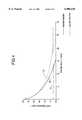
- FIG. 4is a graph plotting the joint cooldown profile temperature of a pipeline joint section joining two sections of flowline pipe, in degrees Fahrenheit against time in hours, which compares temperature loss through a conventionally insulated pipeline joint section against a pipeline joint section flowline insulated according to the invention (i.e., according to the embodiment of FIG. 3, supra).
- FIG. 1shows a cross-section of a flowline pipe 10 of the pipe-in-pipe type having a carrier pipe 12 surrounded by jacket pipe 14.
- Carrier pipe 12is used to transport a produced or processed hydrocarbon fluid mixture 16, typically comprising a mixture of oil, natural gas, and water in varying amounts depending on the wellhead fluid reservoir's characteristics.
- PCMphase change material
- a solid sleeve of PCM materialwould achieve the desired effect and could be produced, for example, by a bulk-encapsulation approach.
- the PCM materialIn a bulk-encapsulation approach, the PCM material would be heated to a temperature above its transition temperature and then poured into the annular region between the carrier pipe 12 and the jacket pipe 14.
- the present inventionalso contemplates use of micro-encapsulated PCM dispersed within conventional insulation material.
- conventional pipe joint insulation materialis cast around a pipe joint using a mold which is removed once the material cures.
- this dispersioncould thus be accomplished by blending the PCM into or along with conventional pipe joint insulation material, and then casting it around a flowline pipe as described. The blending of the PCM material in with the conventional insulation material during such a process should not prove to be difficult.
- FIG. 2shows such an alternate configuration for a flowline pipe, generally designated 20, in which a discrete layer of micro-encapsulated phase change material (PCM) 22 is placed around the carrier pipe 12 and then surrounded by an outer layer of conventional pipeline insulation 24.
- PCMphase change material
- FIGS. 1 and 2disclose a jacket pipe 14, either encasing the insulation 18 having the micro-encapsulated PCM disposed therein (FIG. 1), as well as the embodiment wherein a layer of conventional insulation 24 surrounds the discrete layer of micro-encapsulated PCM, it will be understood that the jacket pipe 14 may be optional in either embodiment of the flowline pipe 10 or 20 according to the present invention.
- a PCMshould be selected with a transition temperature as close as possible to the critical temperature of the produced or processed hydrocarbon fluid mixture 16 (that is, the temperature at which wax or hydrates begin to form) so that the maximum benefit of the PCM is obtained.
- the critical temperature of the produced or processed hydrocarbon fluid mixture 16that is, the temperature at which wax or hydrates begin to form
- the smaller the difference between the PCM transition temperature and the ambient temperaturethe more effective the PCM is to extend the cool down time. The slower the heat loss rate, the longer the stored energy lasts.
- phase change materialis preferably a micro-encapsulated type, such as that made by Frisby Technologies or Phase Change Laboratories.
- phase change materialsare paraffin type and have operating temperatures of between 22-143° F. and -30-220° F., respectively. They are available in a dry powder form.
- Phase change materials available from these two companiesinclude N-Octadecane, N-Heptadecane, N-Hexadecane and pure Hexadecane. These are all examples of what may generally be referred to as paraffinic hydrocarbons.
- phase change materialswhich must be separately encapsulated are available from Shape Energy Resources. These phase change materials include salt hydrate and paraffin based materials and have operating temperatures of between 32-243° F.
- PCMswhich are contemplated for use in the present invention include: alkyl hydrocarbon/silica dry powders; salt-hydrates; and polyethylene glycol.
- AQUATHERMa trademarked material made from resin or thermoplastic available from DynaMonitoring, Incorporated, of Houston, Tex.
- polypropylene foamsyntactic foam
- solid polyurethenesolid polyurethene
- polyurethane foam materiala trademarked material made from resin or thermoplastic available from DynaMonitoring, Incorporated, of Houston, Tex.
- FIG. 3illustrates a third embodiment of the present invention, particularly drawn to a thermally insulated pipe joint, generally designated 100, for joining together two sections of a pipe-in-pipe flowline.
- a thermally insulated pipe jointgenerally designated 100
- Two sections of flowline pipeare shown being joined together by joint 100, and these two flowline pipe sections may be conventionally insulated according to the well-known approaches described above, or they may be insulated flowline pipes manufactured according to the embodiments of FIGS. 1 and 2 (i.e., flowline pipes 10 or 20).
- the thermally insulated pipe joint 100 illustrated in FIG. 3joins two flowline pipe sections generally designated 110 and 120, connected together by a circumferential weld 130.
- Each pipe section 110, 120is comprised of an inner carrier pipe 140 surrounded by an outer jacket pipe 150.
- An annular region 160is defined between inner carrier pipe 140 and outer jacket pipe 150, and this region 160 may be filled with insulation material or evacuated for the same purpose.
- the ends of each pipe section 110, 120are provided with a specially prepared end portion 170 which is welded at one end to the inner carrier pipe 140. The other end is welded at circumferential weld 130 to fluidically interconnect the two pipe sections 110, 120.
- the outer jacket pipe 150 of each pipe section 110, 120is also welded to the end portion 170 at 190.
- a layer of PCM 200Surrounding the central portion of the thermally insulated pipe joint 100, and on the outside surface of the outer jacket pipe 150 is a layer of PCM 200 which, in turn, is surrounded by an outer layer of conventional insulation 210.
- the outer insulation layer 210extends along the axial length of the pipe sections 110, 120 beyond the extremities of the PCM insulation 200.
- the letter designations in FIG. 3denote dimensions of the analyzed pipe joint 100 configuration, and are set forth in Table 1 below:
- the main parameters which would vary as the invention is applied to different diameter pipe or flowline casesinvolves the insulation thickness H, and the required length E of the insulation "sleeve" 210.
- the required length E of the insulation sleeve 210 around the pipe joint 100is related to the thickness H of the insulation and can be determined using standard heat transfer techniques. Considering the outer jacket pipe 150 wall as an insulated fin connected at the tip to an infinite fin, the optimum length E of the insulation sleeve 210 can be found by iterating the length of the insulation sleeve 210 until a minimum heat loss is achieved. For the case examined and studied, the following approximate length to thickness ratios were determined:
- the thickness and length of the inner layer of PCM 200is determined through 2-dimensional heat transfer analysis techniques. To ensure that the PCM 200 is used as efficiently as possible, the PCM 200 is preferably located primarily in regions which will reach temperatures above the transition temperature of the PCM 200 during steady-state operation.
- the produced or processed hydrocarbon fluid mixtures 16 as extracted from subsea subterranean reservoirsare at temperatures of 120° F. or greater. Hydrate formation temperature is pressure dependent. At about 1800 psi, for example, hydrates will form in a light hydrocarbon/water mixture at a temperature of 65° F. In deep waters, where insulation is required, the ambient sea water temperature can be as low as 40° F. or less.
- FIG. 4graphically illustrates a joint cooldown profile temperature of a pipeline joint section joining two pipe-in-pipe flowline sections, in degrees Fahrenheit against time in hours, which compares temperature loss through a conventionally insulated pipeline joint section (curve 60) against a pipeline joint section flowline insulated according to the invention (curve 50) - i.e., made generally according to the embodiment of FIG. 3, supra.
- the cooling characteristics of a flowline joint with standard subsea insulationis shown by curve 60.
- the insulation in the standard flowlinewas two inches thick and extended 30 inches in each direction from the flowline pipe joint, and the thermal conductivity of the insulation was 0.095 Btu/hr-ft-° F.
- the cooling characteristics of a flowline joint insulated according to the inventionis shown by curve 50.
- the flowline according to the inventionhad the same thickness and length of insulation as the standard flowline joint, but a one inch thick layer of phase change material consisting of micro-encapsulated N-Hexadecane was included within the insulation sleeve against the carrier pipe.
- phase change materialin the insulating layer around flowline pipe joints increases the time before the produced or processed hydrocarbon fluid mixture 16 in the carrier pipe 12 reaches the point where hydrates form (65° F.--line 70) during a shut-in condition.
- the initial temperature of the produced or processed hydrocarbon fluid mixture 16 in both pipeswas 120° F. and the ambient seawater temperature was 40° F.
- the time for the produced or processed hydrocarbon fluid mixture 16 contained in the standard insulation flowline joint to reach hydrate formation temperaturewas 12 hours, while the flowline insulated according to the invention maintained the produced or processed hydrocarbon fluid mixture 16 temperature above 65° F. for about 20 hours, or 75% longer.
- the primary advantages of the present inventionare several. First, prolonged cooldown times are provided. Second, the PCM is a passive energy storage system; nothing is required to activate the system, provided that a steady-state temperature above the transition temperature of the fluid contents being conveyed through the flowlines has been previously achieved. Third, human operator intervention is not required for some minimum time after a shut-in, and no chemical injection or electrical power heating is required to prevent wax or hydrates. Finally, the present invention can be manufactured using similar techniques already in use for standard insulation designs for such flowlines.
- thermal energy storage concept according to the present inventionmay be used to insulate a pipe joint, a pipe section, or a portion of an extended flowline.
- flowlines and/or pipe joints for samewhich are assembled from relatively short, discrete pipe sections assembled together with pipe joints therebetween, as well as to flowlines which are made by known pipe reeling techniques where extremely long lengths of continuous pipe are un-reeled off of spools (on land or over water) to make the fowline with a reduced number of pipe joints therebetween.
- flowlineincludes those flowlines made by shorter, interconnected pipe sections, as well as those flowlines made of longer, interconnected sections of pipe laid by pipe reeling or other similar methods, which are connected together. Certain features of the invention may thus be used without a corresponding use of other features, but all such variations and embodiments fall within the scope and equivalents of the following claims.
Landscapes
- Engineering & Computer Science (AREA)
- General Engineering & Computer Science (AREA)
- Mechanical Engineering (AREA)
- Geology (AREA)
- Physics & Mathematics (AREA)
- Life Sciences & Earth Sciences (AREA)
- Mining & Mineral Resources (AREA)
- Fluid Mechanics (AREA)
- Environmental & Geological Engineering (AREA)
- General Life Sciences & Earth Sciences (AREA)
- Geochemistry & Mineralogy (AREA)
- Chemical & Material Sciences (AREA)
- Dispersion Chemistry (AREA)
- Thermal Sciences (AREA)
- Thermal Insulation (AREA)
Abstract
Description
TABLE 1 ______________________________________ Item Dimension (in.) Description ______________________________________ A 8.63 jacket pipe outer diameter B 7.51 jacket pipe inside diameter C 7.00 carrier pipe outside diameter D 6.00 carrier pipe inside diameter E 48-72 total length of the insulation sleeve F 2.0 stub length between welds (as analyzed) G 1.25 weld length H 1-3 insulation thickness ______________________________________
Claims (26)
Priority Applications (1)
| Application Number | Priority Date | Filing Date | Title |
|---|---|---|---|
| US09/023,733US6000438A (en) | 1998-02-13 | 1998-02-13 | Phase change insulation for subsea flowlines |
Applications Claiming Priority (1)
| Application Number | Priority Date | Filing Date | Title |
|---|---|---|---|
| US09/023,733US6000438A (en) | 1998-02-13 | 1998-02-13 | Phase change insulation for subsea flowlines |
Publications (1)
| Publication Number | Publication Date |
|---|---|
| US6000438Atrue US6000438A (en) | 1999-12-14 |
Family
ID=21816895
Family Applications (1)
| Application Number | Title | Priority Date | Filing Date |
|---|---|---|---|
| US09/023,733Expired - LifetimeUS6000438A (en) | 1998-02-13 | 1998-02-13 | Phase change insulation for subsea flowlines |
Country Status (1)
| Country | Link |
|---|---|
| US (1) | US6000438A (en) |
Cited By (85)
| Publication number | Priority date | Publication date | Assignee | Title |
|---|---|---|---|---|
| US6116290A (en)* | 1999-03-16 | 2000-09-12 | J. Ray Mcdermott, S.A. | Internally insulated, corrosion resistant pipeline |
| US6176269B1 (en)* | 1995-12-12 | 2001-01-23 | Uponor Innovation Ab | Co-extruder multilayer plastic pipe, method for producing the same, and device therefor |
| US6179610B1 (en)* | 1999-12-30 | 2001-01-30 | Paul V. Suey | Composite refractory tile for metallurgical furnace members |
| US6305482B1 (en) | 1998-07-29 | 2001-10-23 | James T. Aumann | Method and apparatus for transferring core sample from core retrieval chamber under pressure for transport |
| WO2001088057A1 (en)* | 2000-05-19 | 2001-11-22 | Institut Francais Du Petrole | Method for making a quasi-incompressible phase-change material with low thermal conductivity, and resulting product |
| WO2002012776A1 (en)* | 2000-08-03 | 2002-02-14 | Stolt Offshore Sa | Thermally insulated pipeline bundle |
| WO2002016733A1 (en)* | 2000-08-23 | 2002-02-28 | Fmc Corporation | Hydrate formation prevention in subsea equipment with phase change material |
| US6382259B1 (en)* | 1998-06-22 | 2002-05-07 | Corus Uk Limited | Insulated pipework systems |
| US6517648B1 (en) | 2001-11-02 | 2003-02-11 | Appleton Papers Inc. | Process for preparing a non-woven fibrous web |
| US20030035911A1 (en)* | 2001-07-25 | 2003-02-20 | Dieter Krist | Multi-layer insulating material |
| WO2003024685A1 (en)* | 2001-09-18 | 2003-03-27 | Woon-Yong Park | Plastic pipe of triple layers using plastic salvage and its manufacturing method and apparatus |
| US6575738B1 (en) | 2002-08-16 | 2003-06-10 | Carole S. Nguyen | Composite refractory insulating tile |
| FR2840314A1 (en)* | 2002-06-03 | 2003-12-05 | Inst Francais Du Petrole | THERMAL INSULATION METHOD, METHOD OF PREPARING AN INSULATING GEL AND INSULATING GEL OBTAINED |
| FR2841632A1 (en)* | 2002-07-01 | 2004-01-02 | Bouygues Offshore | "DEVICE FOR THERMAL INSULATION OF AT LEAST ONE SUBSEA PIPE COMPRISING AN INSULATING MATERIAL WITH CONFINED PHASE CHANGE IN POCKETS" |
| US6686745B2 (en) | 2001-07-20 | 2004-02-03 | Shell Oil Company | Apparatus and method for electrical testing of electrically heated pipe-in-pipe pipeline |
| US6688900B2 (en) | 2002-06-25 | 2004-02-10 | Shell Oil Company | Insulating joint for electrically heated pipeline |
| US6714018B2 (en) | 2001-07-20 | 2004-03-30 | Shell Oil Company | Method of commissioning and operating an electrically heated pipe-in-pipe subsea pipeline |
| US20040060693A1 (en)* | 2001-07-20 | 2004-04-01 | Bass Ronald Marshall | Annulus for electrically heated pipe-in-pipe subsea pipeline |
| US20040092626A1 (en)* | 2001-02-07 | 2004-05-13 | Angele Chomard | Method for making a quasi-incompressible phase-change material, shear-thinned and with low heat conductivity |
| US6739803B2 (en)* | 2001-07-20 | 2004-05-25 | Shell Oil Company | Method of installation of electrically heated pipe-in-pipe subsea pipeline |
| US20040100273A1 (en)* | 2002-11-08 | 2004-05-27 | Liney David J. | Testing electrical integrity of electrically heated subsea pipelines |
| DE10256550A1 (en)* | 2002-12-04 | 2004-06-24 | Abb Research Ltd. | Oil or gas feed connection for seabed has cylindrical core with outer and inner insulation layers and phase change heat storage material within core bore |
| DE10256551A1 (en)* | 2002-12-04 | 2004-06-24 | Abb Research Ltd. | Thermal insulation, for insulating pipelines for conveying crude oil and natural gas, comprises heat insulation having connecting components with polymer in structure matrix, in which phase-changing material is embedded |
| DE10256553A1 (en)* | 2002-12-04 | 2004-06-24 | Abb Research Ltd. | Thermal insulation, for insulating pipelines for conveying crude oil and natural gas, comprises matrix made from microporous material based on silicate or polymer containing hollow spheres and additive |
| US20040141539A1 (en)* | 2003-01-07 | 2004-07-22 | Adon Delgado | Phase-change heat exchanger |
| US20040170806A1 (en)* | 2003-02-28 | 2004-09-02 | University Of Colorado Research Foundation | Tile structures having phase change material (PCM) component for use in flooring and ceilings |
| DE10308801A1 (en)* | 2003-02-27 | 2004-09-09 | Abb Research Ltd. | Thermal insulation jacket, for sub-surface marine oil or gas pipeline, is assembled from laminated modules clamped together and encased in water-impermeable foil |
| US20050236061A1 (en)* | 2002-07-30 | 2005-10-27 | Coppe/Ufrj - Coordenacao Dos Programas De Pos Graduacao De Engenharia Do Universidade | Sandwich pipes for ultra-deep waters |
| WO2005113631A1 (en)* | 2004-05-18 | 2005-12-01 | Basf Aktiengesellschaft | Syntactic polyurethanes and the use thereof of for off-shore shore damping |
| US6978825B1 (en) | 1998-12-31 | 2005-12-27 | Bouygues Offshore | Device and process for the heat insulation of at least one underwater pipe at great depth |
| US20060037756A1 (en)* | 2004-08-20 | 2006-02-23 | Sonsub Inc. | Method and apparatus for installing subsea insulation |
| US20060131027A1 (en)* | 2003-03-18 | 2006-06-22 | Giovanni Chiesa | Device for heating and thermally insulating at least one undersea pipeline |
| WO2006106406A1 (en)* | 2005-04-05 | 2006-10-12 | Vetco Gray Scandinavia As | An arrangement and a method for heat transport and use in connection with subsea equipment |
| US20070100027A1 (en)* | 2003-12-11 | 2007-05-03 | Basf Aktiengesellschaft | Syntactic polyurethanes and their utilization for off-shore insulation |
| US20070247063A1 (en)* | 2004-05-21 | 2007-10-25 | Toray Industries Inc. | Light-Emitting Device Material and Light-Emitting Device |
| US20080023092A1 (en)* | 2006-07-31 | 2008-01-31 | Assaf Klar | Method For Designing And Implementing Improved Longitudinal Flexibility Multilayered Pipeline |
| EP1857725A3 (en)* | 2006-05-18 | 2008-07-02 | Corus UK Limited | Insulation of pipe-in-pipe systems |
| US20090050328A1 (en)* | 2004-08-20 | 2009-02-26 | Bath William R | Method and system for installing subsea insulation |
| US20100154917A1 (en)* | 2006-08-10 | 2010-06-24 | Shawcor Ltd. | Thermally insulated pipe for use at very high temperatures |
| WO2010076118A1 (en)* | 2008-12-17 | 2010-07-08 | Basf Se | Laminar component made from composite material |
| WO2010079371A1 (en) | 2009-01-06 | 2010-07-15 | Fodor Andras | Storage cabinet for storing flat batches of male hygienic wipes |
| WO2010093400A1 (en)* | 2009-02-11 | 2010-08-19 | Exxonmobil Upstream Research Company | Methods and systems of regenerative heat exchange |
| WO2010099509A2 (en) | 2009-02-28 | 2010-09-02 | Martin Mittelmark | System and method for using recyclables for thermal storage |
| CN101832108A (en)* | 2010-05-07 | 2010-09-15 | 湖北贵族真空科技股份有限公司 | Vacuum oil tubing coupling |
| US20100260551A1 (en)* | 2007-10-02 | 2010-10-14 | Logstor A/S | Bendable Pre-Insulated Pipeline Assembly |
| US20110186169A1 (en)* | 2008-10-29 | 2011-08-04 | Pionetti Francois-Regis | Coaxial Pipe Assembly Including a Thermalloy Insulating Sleeve |
| WO2011161472A1 (en)* | 2010-06-26 | 2011-12-29 | Trellborg Offshore Uk Limited | Passive thermal management system for liquid pipelines |
| US20120152558A1 (en)* | 2009-05-26 | 2012-06-21 | Framo Engineering As | Heat transport dead leg |
| CN102536164A (en)* | 2010-12-21 | 2012-07-04 | 熊斌辉 | Ultrahigh-temperature well completion technology |
| US20120261019A1 (en)* | 2009-12-28 | 2012-10-18 | National Oilwell Varco Denmark I/S | unbonded, flexible pipe |
| US20130092389A1 (en)* | 2011-08-29 | 2013-04-18 | Quangen Du | Piping system having an insulated annulus |
| WO2013110947A1 (en)* | 2012-01-25 | 2013-08-01 | Subsea 7 Limited | Connections for subsea pipe-in-pipe structures |
| EP2712893A1 (en) | 2012-10-01 | 2014-04-02 | Basf Se | Pipeline with heat storage properties |
| EP1784608A4 (en)* | 2004-03-26 | 2014-04-30 | Fluor Tech Corp | Cryogenic pipeline configurations and methods |
| CN103850653A (en)* | 2014-02-17 | 2014-06-11 | 胜利油田孚瑞特石油装备有限责任公司 | Heat-insulating oil sleeve and manufacturing method thereof |
| EP2743285A1 (en) | 2012-12-13 | 2014-06-18 | Basf Se | Hydrolysis-stable polyurethane for use in offshore applications |
| EP2743284A1 (en) | 2012-12-13 | 2014-06-18 | Basf Se | Hydrolysis-stable polyurethane for the coating of elements in marine applications |
| CN104818852A (en)* | 2015-04-02 | 2015-08-05 | 张鑫浩 | Conveying pipe sleeve for pumping concrete construction |
| WO2016142452A1 (en) | 2015-03-11 | 2016-09-15 | Basf Se | Method for producing compact polyurethanes with improved hydrolytic stability |
| US9506307B2 (en) | 2011-03-16 | 2016-11-29 | Corpro Technologies Canada Ltd. | High pressure coring assembly and method |
| US20170059079A1 (en)* | 2015-08-31 | 2017-03-02 | General Electric Company | Insulated fluid conduit |
| US20170059080A1 (en)* | 2015-08-31 | 2017-03-02 | General Electric Company | Insulated fluid conduit |
| US20170067582A1 (en)* | 2015-09-08 | 2017-03-09 | Itp Sa | Method of manufacturing a pipe segment |
| US20170067326A1 (en)* | 2015-09-08 | 2017-03-09 | Itp Sa | Method and apparatus for producing hydrocarbons from one subsea well |
| US20170122487A1 (en)* | 2015-10-30 | 2017-05-04 | Platinum Insulating Services Ltd. | Encapsulation System and Kit for a Length of Pipe Disposed Underground |
| CN106703707A (en)* | 2015-11-16 | 2017-05-24 | 胜利油田胜机石油装备有限公司 | Composite-structure heat-insulating oil pipe |
| CN106761440A (en)* | 2015-11-24 | 2017-05-31 | 中国石油化工股份有限公司 | Aerogel heat-proof oil pipe |
| US9714374B2 (en) | 2011-07-15 | 2017-07-25 | Exxonmobil Upstream Research Company | Protecting a fluid stream from fouling |
| US9851157B2 (en)* | 2011-06-22 | 2017-12-26 | Ge Oil & Gas Uk Limited | Method and apparatus for maintaining a minimum temperature in a fluid |
| CN107527873A (en)* | 2016-06-15 | 2017-12-29 | Abb瑞士股份有限公司 | High-voltage power electronic module for subsea use |
| US9890895B2 (en) | 2012-10-01 | 2018-02-13 | Basf Se | Pipeline with heat-storing properties |
| US9938799B2 (en)* | 2015-09-03 | 2018-04-10 | Fmc Technologies, Inc. | High temperature insulation system and method |
| WO2018138241A1 (en) | 2017-01-30 | 2018-08-02 | Swisspor Management Ag | Method for maintaining the temperature of fluid media |
| CN108558281A (en)* | 2018-01-19 | 2018-09-21 | 中国石油大学(北京) | A kind of seabed Sandwich pipeline and its special phase-change microcapsule |
| US10330393B2 (en) | 2014-02-26 | 2019-06-25 | Uchicago Argonne, Llc | Modular latent heat thermal energy storage systems |
| US10442885B2 (en) | 2012-12-13 | 2019-10-15 | Basf Se | Hydrolysis-stable polyurethane for coating elements in maritime applications |
| CN110345317A (en)* | 2018-04-08 | 2019-10-18 | 上海纳川核能新材料技术有限公司 | A kind of preparation method and products thereof of anti-freezing type polyethylene reinforced composite pipe |
| US10487986B2 (en) | 2017-06-16 | 2019-11-26 | Exxonmobil Upstream Research Company | Protecting a fluid stream from fouling |
| US20200041216A1 (en)* | 2017-07-12 | 2020-02-06 | Uchicago Argonne, Llc | Method for buffering latent heat thermal energy |
| US10590742B2 (en) | 2011-07-15 | 2020-03-17 | Exxonmobil Upstream Research Company | Protecting a fluid stream from fouling using a phase change material |
| CN111454694A (en)* | 2020-04-03 | 2020-07-28 | 中国石油大学(北京) | Phase change thermal insulation material, preparation method and application thereof |
| WO2021142304A1 (en)* | 2020-01-10 | 2021-07-15 | Phase Change Energy Solutions, Inc. | Systems and methods for district heating and cooling |
| US11473717B2 (en)* | 2019-12-20 | 2022-10-18 | Shinda (Tangshan) Creative Oil & Gas Equipment Co., Ltd. | Ultra-long thermally insulated pipeline and forming method thereof |
| GB2615545A (en)* | 2022-02-10 | 2023-08-16 | Baker Hughes Energy Technology UK Ltd | Subsea installation with PCM heat storing member |
| US20240344649A1 (en)* | 2021-08-02 | 2024-10-17 | Xgs Energy, Inc. | Insulated Welded Joint for Pipe-in-Pipe systems |
Citations (31)
| Publication number | Priority date | Publication date | Assignee | Title |
|---|---|---|---|---|
| US23545A (en)* | 1859-04-12 | Fkancis h | ||
| USRE23545E (en) | 1952-09-09 | Concentric pipe insulator and spacer | ||
| US2963045A (en)* | 1958-03-25 | 1960-12-06 | Exxon Research Engineering Co | Coated pipeline and method of coating metal article to protect it against corrosion |
| US3151633A (en)* | 1961-03-29 | 1964-10-06 | Owens Corning Fiberglass Corp | Shaped thermal insulation for pipe |
| US3480493A (en)* | 1965-08-27 | 1969-11-25 | Exxon Research Engineering Co | Method and apparatus for spray foam insulating a pipe |
| US3543804A (en)* | 1965-09-13 | 1970-12-01 | Thermal Conduits Inc | Insulating structure for underground pipes |
| US3626987A (en)* | 1968-10-03 | 1971-12-14 | Kabelund Metallwerke Ag | Coaxial pipe system with thermal insulation |
| US4000760A (en)* | 1973-11-05 | 1977-01-04 | William C. Heller, Jr. | Plastic hose having embedded reinforcing braid |
| US4028785A (en)* | 1973-06-06 | 1977-06-14 | Yorkshire Imperial Metals Limited | Tubular products |
| US4104171A (en)* | 1976-12-30 | 1978-08-01 | Union Oil Company Of California | Method for transporting waxy oils by pipeline |
| US4162093A (en)* | 1976-06-14 | 1979-07-24 | Frantisek Sigmund | Heat-insulated pipe-lines |
| US4287245A (en)* | 1978-04-28 | 1981-09-01 | Nippon Asbestos Co., Ltd. | Heat insulator for pipe lines |
| US4294078A (en)* | 1977-04-26 | 1981-10-13 | Calmac Manufacturing Corporation | Method and system for the compact storage of heat and coolness by phase change materials |
| US4346739A (en)* | 1979-10-24 | 1982-08-31 | Usui Kokusai Sangyo Kabushiki Kaisha | Composite metal tubing |
| US4348243A (en)* | 1977-10-24 | 1982-09-07 | Wacker-Chemie Gmbh | Thermal insulation, a process for preparing said insulation and a pipe insulated therewith |
| US4367768A (en)* | 1979-02-24 | 1983-01-11 | Heraeus Quarzschmelze Gmbh | Refractory protective tube for the heat treatment of semiconductor components |
| US4403645A (en)* | 1978-07-12 | 1983-09-13 | Calmac Manufacturing Corporation | Compact storage of seat and coolness by phase change materials while preventing stratification |
| US4421661A (en)* | 1981-06-19 | 1983-12-20 | Institute Of Gas Technology | High-temperature direct-contact thermal energy storage using phase-change media |
| US4512388A (en)* | 1981-06-19 | 1985-04-23 | Institute Of Gas Technology | High-temperature direct-contact thermal energy storage using phase-change media |
| US4606378A (en)* | 1981-04-07 | 1986-08-19 | Meyer Erik B | Weightcoated subsea pipeline section |
| WO1987004768A1 (en)* | 1986-02-06 | 1987-08-13 | Norsk Hydro A.S. | Insulation and weight coating for subsea pipelines and method for production of the same |
| US4798769A (en)* | 1983-06-17 | 1989-01-17 | Mitsubishi Denki Kabushiki Kaisha | Electrode supporting conduit tube for electrical heating of underground hydrocarbon resources |
| US4824705A (en)* | 1985-09-04 | 1989-04-25 | Skega Ab | Insulated pipe |
| US4995427A (en)* | 1988-06-30 | 1991-02-26 | Metalpraecis Berchem & Schaberg Gesellschaft Fur Metallformgebung Mit Beschrankter Haftung | Pipe section, especially for abrasive and/or corrosive material pipelines |
| US5307842A (en)* | 1990-12-21 | 1994-05-03 | Coflexip | Flexible conduit with improved thermal protection comprising cork |
| US5380571A (en)* | 1992-06-19 | 1995-01-10 | The Yokohama Rubber Co., Ltd. | Thermoplastic elastomer hose having excellent flexibility |
| US5390705A (en)* | 1992-01-29 | 1995-02-21 | Technoflow Tube-Systems Gmbh | Cold-resistant fuel-line hose |
| US5458441A (en)* | 1991-04-23 | 1995-10-17 | Shell Oil Company | Pipe section for installation into a subsea pipeline |
| US5476343A (en)* | 1992-11-30 | 1995-12-19 | Sumner; Glen R. | Offshore pipeline insulated with a cementitious coating |
| US5525155A (en)* | 1994-05-05 | 1996-06-11 | Union Oil Company Of California | Superplasticizer-concrete composition and method of preparation |
| US5654060A (en)* | 1995-06-16 | 1997-08-05 | The Boeing Company | High temperature insulation system |
- 1998
- 1998-02-13USUS09/023,733patent/US6000438A/ennot_activeExpired - Lifetime
Patent Citations (31)
| Publication number | Priority date | Publication date | Assignee | Title |
|---|---|---|---|---|
| USRE23545E (en) | 1952-09-09 | Concentric pipe insulator and spacer | ||
| US23545A (en)* | 1859-04-12 | Fkancis h | ||
| US2963045A (en)* | 1958-03-25 | 1960-12-06 | Exxon Research Engineering Co | Coated pipeline and method of coating metal article to protect it against corrosion |
| US3151633A (en)* | 1961-03-29 | 1964-10-06 | Owens Corning Fiberglass Corp | Shaped thermal insulation for pipe |
| US3480493A (en)* | 1965-08-27 | 1969-11-25 | Exxon Research Engineering Co | Method and apparatus for spray foam insulating a pipe |
| US3543804A (en)* | 1965-09-13 | 1970-12-01 | Thermal Conduits Inc | Insulating structure for underground pipes |
| US3626987A (en)* | 1968-10-03 | 1971-12-14 | Kabelund Metallwerke Ag | Coaxial pipe system with thermal insulation |
| US4028785A (en)* | 1973-06-06 | 1977-06-14 | Yorkshire Imperial Metals Limited | Tubular products |
| US4000760A (en)* | 1973-11-05 | 1977-01-04 | William C. Heller, Jr. | Plastic hose having embedded reinforcing braid |
| US4162093A (en)* | 1976-06-14 | 1979-07-24 | Frantisek Sigmund | Heat-insulated pipe-lines |
| US4104171A (en)* | 1976-12-30 | 1978-08-01 | Union Oil Company Of California | Method for transporting waxy oils by pipeline |
| US4294078A (en)* | 1977-04-26 | 1981-10-13 | Calmac Manufacturing Corporation | Method and system for the compact storage of heat and coolness by phase change materials |
| US4348243A (en)* | 1977-10-24 | 1982-09-07 | Wacker-Chemie Gmbh | Thermal insulation, a process for preparing said insulation and a pipe insulated therewith |
| US4287245A (en)* | 1978-04-28 | 1981-09-01 | Nippon Asbestos Co., Ltd. | Heat insulator for pipe lines |
| US4403645A (en)* | 1978-07-12 | 1983-09-13 | Calmac Manufacturing Corporation | Compact storage of seat and coolness by phase change materials while preventing stratification |
| US4367768A (en)* | 1979-02-24 | 1983-01-11 | Heraeus Quarzschmelze Gmbh | Refractory protective tube for the heat treatment of semiconductor components |
| US4346739A (en)* | 1979-10-24 | 1982-08-31 | Usui Kokusai Sangyo Kabushiki Kaisha | Composite metal tubing |
| US4606378A (en)* | 1981-04-07 | 1986-08-19 | Meyer Erik B | Weightcoated subsea pipeline section |
| US4421661A (en)* | 1981-06-19 | 1983-12-20 | Institute Of Gas Technology | High-temperature direct-contact thermal energy storage using phase-change media |
| US4512388A (en)* | 1981-06-19 | 1985-04-23 | Institute Of Gas Technology | High-temperature direct-contact thermal energy storage using phase-change media |
| US4798769A (en)* | 1983-06-17 | 1989-01-17 | Mitsubishi Denki Kabushiki Kaisha | Electrode supporting conduit tube for electrical heating of underground hydrocarbon resources |
| US4824705A (en)* | 1985-09-04 | 1989-04-25 | Skega Ab | Insulated pipe |
| WO1987004768A1 (en)* | 1986-02-06 | 1987-08-13 | Norsk Hydro A.S. | Insulation and weight coating for subsea pipelines and method for production of the same |
| US4995427A (en)* | 1988-06-30 | 1991-02-26 | Metalpraecis Berchem & Schaberg Gesellschaft Fur Metallformgebung Mit Beschrankter Haftung | Pipe section, especially for abrasive and/or corrosive material pipelines |
| US5307842A (en)* | 1990-12-21 | 1994-05-03 | Coflexip | Flexible conduit with improved thermal protection comprising cork |
| US5458441A (en)* | 1991-04-23 | 1995-10-17 | Shell Oil Company | Pipe section for installation into a subsea pipeline |
| US5390705A (en)* | 1992-01-29 | 1995-02-21 | Technoflow Tube-Systems Gmbh | Cold-resistant fuel-line hose |
| US5380571A (en)* | 1992-06-19 | 1995-01-10 | The Yokohama Rubber Co., Ltd. | Thermoplastic elastomer hose having excellent flexibility |
| US5476343A (en)* | 1992-11-30 | 1995-12-19 | Sumner; Glen R. | Offshore pipeline insulated with a cementitious coating |
| US5525155A (en)* | 1994-05-05 | 1996-06-11 | Union Oil Company Of California | Superplasticizer-concrete composition and method of preparation |
| US5654060A (en)* | 1995-06-16 | 1997-08-05 | The Boeing Company | High temperature insulation system |
Non-Patent Citations (2)
| Title |
|---|
| Excerpt from an internal, proprietary, McDermott Technology, Inc. Report dated Jul. 24, 1997 comprising an Appendix of Vendor Supplied Information provided via personal communications to inventor Ohrn from Frisby Technologies and UDRI Phase Change Laboratories, pp. 16 63.* |
| Excerpt from an internal, proprietary, McDermott Technology, Inc. Report dated Jul. 24, 1997 comprising an Appendix of Vendor Supplied Information provided via personal communications to inventor Ohrn from Frisby Technologies and UDRI-Phase Change Laboratories, pp. 16-63. |
Cited By (150)
| Publication number | Priority date | Publication date | Assignee | Title |
|---|---|---|---|---|
| US6176269B1 (en)* | 1995-12-12 | 2001-01-23 | Uponor Innovation Ab | Co-extruder multilayer plastic pipe, method for producing the same, and device therefor |
| US6382259B1 (en)* | 1998-06-22 | 2002-05-07 | Corus Uk Limited | Insulated pipework systems |
| US6305482B1 (en) | 1998-07-29 | 2001-10-23 | James T. Aumann | Method and apparatus for transferring core sample from core retrieval chamber under pressure for transport |
| US6378631B1 (en)* | 1998-07-29 | 2002-04-30 | James T. Aumann | Apparatus for recovering core samples at in situ conditions |
| US6659204B2 (en) | 1998-07-29 | 2003-12-09 | Japan National Oil Corporation | Method and apparatus for recovering core samples under pressure |
| US6978825B1 (en) | 1998-12-31 | 2005-12-27 | Bouygues Offshore | Device and process for the heat insulation of at least one underwater pipe at great depth |
| US6116290A (en)* | 1999-03-16 | 2000-09-12 | J. Ray Mcdermott, S.A. | Internally insulated, corrosion resistant pipeline |
| US6179610B1 (en)* | 1999-12-30 | 2001-01-30 | Paul V. Suey | Composite refractory tile for metallurgical furnace members |
| WO2001088057A1 (en)* | 2000-05-19 | 2001-11-22 | Institut Francais Du Petrole | Method for making a quasi-incompressible phase-change material with low thermal conductivity, and resulting product |
| FR2809115A1 (en)* | 2000-05-19 | 2001-11-23 | Bouygues Offshore | Quasi-incompressible phase-change material production, used for thermal insulating containers and ducts, comprises combining phase change material and thickener |
| US20040030016A1 (en)* | 2000-05-19 | 2004-02-12 | Angele Chomard | Method for making a quasi-incompressible phase-change material with low thermal conductivity, and resulting product |
| US7105104B2 (en) | 2000-05-19 | 2006-09-12 | Bouygues Offshore | Method for making a quasi-incompressible phase-change material with low thermal conductivity, and resulting product |
| CN1295294C (en)* | 2000-05-19 | 2007-01-17 | 法国石油研究所 | Method for making quasi-incompressible phase-change material with low thermal conductivity, and resulting product |
| WO2002012776A1 (en)* | 2000-08-03 | 2002-02-14 | Stolt Offshore Sa | Thermally insulated pipeline bundle |
| WO2002016733A1 (en)* | 2000-08-23 | 2002-02-28 | Fmc Corporation | Hydrate formation prevention in subsea equipment with phase change material |
| US6415868B1 (en)* | 2000-08-23 | 2002-07-09 | Fmc Corporation | Method and apparatus for preventing the formation of alkane hydrates in subsea equipment |
| GB2383815A (en)* | 2000-08-23 | 2003-07-09 | Fmc Corp | Hydrate formation prevention in subsea equipment with phase change material |
| GB2383815B (en)* | 2000-08-23 | 2004-12-29 | Fmc Corp | Hydrate formation prevention in subsea equipment with phase change material |
| US7320770B2 (en)* | 2001-02-07 | 2008-01-22 | Saipem S.A. | Method for making a quasi-incompressible phase-change material, shear-thinned and with low heat conductivity |
| US20040092626A1 (en)* | 2001-02-07 | 2004-05-13 | Angele Chomard | Method for making a quasi-incompressible phase-change material, shear-thinned and with low heat conductivity |
| US6814146B2 (en) | 2001-07-20 | 2004-11-09 | Shell Oil Company | Annulus for electrically heated pipe-in-pipe subsea pipeline |
| US6686745B2 (en) | 2001-07-20 | 2004-02-03 | Shell Oil Company | Apparatus and method for electrical testing of electrically heated pipe-in-pipe pipeline |
| US6714018B2 (en) | 2001-07-20 | 2004-03-30 | Shell Oil Company | Method of commissioning and operating an electrically heated pipe-in-pipe subsea pipeline |
| US20040060693A1 (en)* | 2001-07-20 | 2004-04-01 | Bass Ronald Marshall | Annulus for electrically heated pipe-in-pipe subsea pipeline |
| US6739803B2 (en)* | 2001-07-20 | 2004-05-25 | Shell Oil Company | Method of installation of electrically heated pipe-in-pipe subsea pipeline |
| US20030035911A1 (en)* | 2001-07-25 | 2003-02-20 | Dieter Krist | Multi-layer insulating material |
| WO2003024685A1 (en)* | 2001-09-18 | 2003-03-27 | Woon-Yong Park | Plastic pipe of triple layers using plastic salvage and its manufacturing method and apparatus |
| US6517648B1 (en) | 2001-11-02 | 2003-02-11 | Appleton Papers Inc. | Process for preparing a non-woven fibrous web |
| US6843871B2 (en) | 2001-11-02 | 2005-01-18 | Appleton Papers Inc. | Process for preparing a non-woven fibrous web |
| US20030087058A1 (en)* | 2001-11-02 | 2003-05-08 | Appleton Papers Inc. | Process for preparing a non-woven fibrous web |
| FR2840314A1 (en)* | 2002-06-03 | 2003-12-05 | Inst Francais Du Petrole | THERMAL INSULATION METHOD, METHOD OF PREPARING AN INSULATING GEL AND INSULATING GEL OBTAINED |
| WO2003102105A1 (en)* | 2002-06-03 | 2003-12-11 | Institut Francais Du Petrole | Method for thermal insulation, method for preparation of an insulating gel and insulating gel produced thus |
| US20050214547A1 (en)* | 2002-06-03 | 2005-09-29 | David Pasquier | Method for thermal insulation, method for preparation of an insulating gel and insulating gel produced thus |
| US6688900B2 (en) | 2002-06-25 | 2004-02-10 | Shell Oil Company | Insulating joint for electrically heated pipeline |
| FR2841632A1 (en)* | 2002-07-01 | 2004-01-02 | Bouygues Offshore | "DEVICE FOR THERMAL INSULATION OF AT LEAST ONE SUBSEA PIPE COMPRISING AN INSULATING MATERIAL WITH CONFINED PHASE CHANGE IN POCKETS" |
| US7896033B2 (en) | 2002-07-01 | 2011-03-01 | Saipem S.A. | Device for thermal insulation of at least a submarine pipeline comprising a phase-change material confined in jackets |
| WO2004003424A1 (en)* | 2002-07-01 | 2004-01-08 | Saipem S.A. | Device for thermal insulation of at least a submarine pipeline comprising a phase-change material confined in jackets |
| US20050241717A1 (en)* | 2002-07-01 | 2005-11-03 | Raymond Hallot | Device for thermal insulation of at least a submarine pipeline comprising a phase-change material confined in jackets |
| US20050236061A1 (en)* | 2002-07-30 | 2005-10-27 | Coppe/Ufrj - Coordenacao Dos Programas De Pos Graduacao De Engenharia Do Universidade | Sandwich pipes for ultra-deep waters |
| US6575738B1 (en) | 2002-08-16 | 2003-06-10 | Carole S. Nguyen | Composite refractory insulating tile |
| US20040100273A1 (en)* | 2002-11-08 | 2004-05-27 | Liney David J. | Testing electrical integrity of electrically heated subsea pipelines |
| US6937030B2 (en) | 2002-11-08 | 2005-08-30 | Shell Oil Company | Testing electrical integrity of electrically heated subsea pipelines |
| DE10256551A1 (en)* | 2002-12-04 | 2004-06-24 | Abb Research Ltd. | Thermal insulation, for insulating pipelines for conveying crude oil and natural gas, comprises heat insulation having connecting components with polymer in structure matrix, in which phase-changing material is embedded |
| DE10256550A1 (en)* | 2002-12-04 | 2004-06-24 | Abb Research Ltd. | Oil or gas feed connection for seabed has cylindrical core with outer and inner insulation layers and phase change heat storage material within core bore |
| DE10256553A1 (en)* | 2002-12-04 | 2004-06-24 | Abb Research Ltd. | Thermal insulation, for insulating pipelines for conveying crude oil and natural gas, comprises matrix made from microporous material based on silicate or polymer containing hollow spheres and additive |
| US7106777B2 (en) | 2003-01-07 | 2006-09-12 | The Boeing Company | Phase-change heat exchanger |
| US20040141539A1 (en)* | 2003-01-07 | 2004-07-22 | Adon Delgado | Phase-change heat exchanger |
| DE10308801A1 (en)* | 2003-02-27 | 2004-09-09 | Abb Research Ltd. | Thermal insulation jacket, for sub-surface marine oil or gas pipeline, is assembled from laminated modules clamped together and encased in water-impermeable foil |
| US20040170806A1 (en)* | 2003-02-28 | 2004-09-02 | University Of Colorado Research Foundation | Tile structures having phase change material (PCM) component for use in flooring and ceilings |
| US20090223160A1 (en)* | 2003-02-28 | 2009-09-10 | Colorado State University Research Foundation (Csurf) | Tile structures having phase change material (PCM) component for use in floorings and ceilings |
| US20060131027A1 (en)* | 2003-03-18 | 2006-06-22 | Giovanni Chiesa | Device for heating and thermally insulating at least one undersea pipeline |
| US7367398B2 (en)* | 2003-03-18 | 2008-05-06 | Saipem S.A. | Device for heating and thermally insulating at least one undersea pipeline |
| WO2005057119A1 (en)* | 2003-12-08 | 2005-06-23 | The Boeing Company | Phase-change heat exchanger |
| US20110023989A1 (en)* | 2003-12-11 | 2011-02-03 | Basf Aktiengesellschaft | Syntactic polyurethanes and their utilization for off-shore insulation |
| US20070100027A1 (en)* | 2003-12-11 | 2007-05-03 | Basf Aktiengesellschaft | Syntactic polyurethanes and their utilization for off-shore insulation |
| EP1784608A4 (en)* | 2004-03-26 | 2014-04-30 | Fluor Tech Corp | Cryogenic pipeline configurations and methods |
| US8998267B2 (en) | 2004-03-26 | 2015-04-07 | Fluor Technologies Corporation | Cryogenic pipeline configurations and methods |
| NO342698B1 (en)* | 2004-03-26 | 2018-07-09 | Fluor Tech Corp | Cryogenic pipeline designs and methods |
| US20070240781A1 (en)* | 2004-05-18 | 2007-10-18 | Basf Aktiengesellschaft | Syntactic Polyurethanes and the Use Thereof of for Off-Shore Shore Damping |
| WO2005113631A1 (en)* | 2004-05-18 | 2005-12-01 | Basf Aktiengesellschaft | Syntactic polyurethanes and the use thereof of for off-shore shore damping |
| US20070247063A1 (en)* | 2004-05-21 | 2007-10-25 | Toray Industries Inc. | Light-Emitting Device Material and Light-Emitting Device |
| US20090050328A1 (en)* | 2004-08-20 | 2009-02-26 | Bath William R | Method and system for installing subsea insulation |
| US8006763B2 (en)* | 2004-08-20 | 2011-08-30 | Saipem America Inc. | Method and system for installing subsea insulation |
| US20060037756A1 (en)* | 2004-08-20 | 2006-02-23 | Sonsub Inc. | Method and apparatus for installing subsea insulation |
| WO2006106406A1 (en)* | 2005-04-05 | 2006-10-12 | Vetco Gray Scandinavia As | An arrangement and a method for heat transport and use in connection with subsea equipment |
| US20090090500A1 (en)* | 2005-04-05 | 2009-04-09 | Vetco Gray Scandinavia As | Arrangement and a Method for Heat Transport and Use in Connection With Subsea Equipment |
| GB2439026B (en)* | 2005-04-05 | 2009-10-28 | Vetco Gray Scandinavia As | An arrangement for heat transport or cooling |
| GB2439026A (en)* | 2005-04-05 | 2007-12-12 | Vecto Gray Scandinavia As | An arrangement and a method for heat transport and use in connection with subsea equipment |
| US8267166B2 (en) | 2005-04-05 | 2012-09-18 | Vetco Gray Scandinavia As | Arrangement and method for heat transport |
| EP1857725A3 (en)* | 2006-05-18 | 2008-07-02 | Corus UK Limited | Insulation of pipe-in-pipe systems |
| US20080023092A1 (en)* | 2006-07-31 | 2008-01-31 | Assaf Klar | Method For Designing And Implementing Improved Longitudinal Flexibility Multilayered Pipeline |
| US20100154917A1 (en)* | 2006-08-10 | 2010-06-24 | Shawcor Ltd. | Thermally insulated pipe for use at very high temperatures |
| US20100260551A1 (en)* | 2007-10-02 | 2010-10-14 | Logstor A/S | Bendable Pre-Insulated Pipeline Assembly |
| US8651148B2 (en)* | 2007-10-02 | 2014-02-18 | Logstor A/S | Bendable pre-insulated pipeline assembly |
| US20110186169A1 (en)* | 2008-10-29 | 2011-08-04 | Pionetti Francois-Regis | Coaxial Pipe Assembly Including a Thermalloy Insulating Sleeve |
| US9267637B2 (en)* | 2008-10-29 | 2016-02-23 | Saipem S.A. | Coaxial pipe assembly including a thermally insulating sleeve |
| CN102317073A (en)* | 2008-12-17 | 2012-01-11 | 巴斯夫欧洲公司 | Laminar component made from composite material |
| JP2012512063A (en)* | 2008-12-17 | 2012-05-31 | ビーエーエスエフ ソシエタス・ヨーロピア | Planar component made of composite material |
| CN102317073B (en)* | 2008-12-17 | 2014-07-16 | 巴斯夫欧洲公司 | Laminar component made from composite material |
| WO2010076118A1 (en)* | 2008-12-17 | 2010-07-08 | Basf Se | Laminar component made from composite material |
| RU2531347C2 (en)* | 2008-12-17 | 2014-10-20 | Басф Се | Sheet construction element from composite material |
| US8491992B2 (en) | 2008-12-17 | 2013-07-23 | Basf Se | Laminar component made from composite material |
| WO2010079371A1 (en) | 2009-01-06 | 2010-07-15 | Fodor Andras | Storage cabinet for storing flat batches of male hygienic wipes |
| WO2010093400A1 (en)* | 2009-02-11 | 2010-08-19 | Exxonmobil Upstream Research Company | Methods and systems of regenerative heat exchange |
| WO2010099509A2 (en) | 2009-02-28 | 2010-09-02 | Martin Mittelmark | System and method for using recyclables for thermal storage |
| US20120152558A1 (en)* | 2009-05-26 | 2012-06-21 | Framo Engineering As | Heat transport dead leg |
| US9328586B2 (en)* | 2009-05-26 | 2016-05-03 | Framo Engineering As | Heat transport dead leg |
| US9057465B2 (en)* | 2009-12-28 | 2015-06-16 | National Oilwell Varco Denmark I/S | Unbonded, flexible pipe |
| US20120261019A1 (en)* | 2009-12-28 | 2012-10-18 | National Oilwell Varco Denmark I/S | unbonded, flexible pipe |
| EP2519764A4 (en)* | 2009-12-28 | 2017-04-26 | National Oilwell Varco Denmark I/S | An unbonded, flexible pipe |
| CN101832108B (en)* | 2010-05-07 | 2013-02-27 | 湖北贵族真空科技股份有限公司 | Vacuum oil tubing coupling |
| CN101832108A (en)* | 2010-05-07 | 2010-09-15 | 湖北贵族真空科技股份有限公司 | Vacuum oil tubing coupling |
| WO2011161472A1 (en)* | 2010-06-26 | 2011-12-29 | Trellborg Offshore Uk Limited | Passive thermal management system for liquid pipelines |
| CN102536164A (en)* | 2010-12-21 | 2012-07-04 | 熊斌辉 | Ultrahigh-temperature well completion technology |
| US9506307B2 (en) | 2011-03-16 | 2016-11-29 | Corpro Technologies Canada Ltd. | High pressure coring assembly and method |
| US9851157B2 (en)* | 2011-06-22 | 2017-12-26 | Ge Oil & Gas Uk Limited | Method and apparatus for maintaining a minimum temperature in a fluid |
| US10197339B2 (en) | 2011-06-22 | 2019-02-05 | Ge Oil & Gas Uk Limited | Method and apparatus for maintaining a minimum temperature in a fluid |
| US10590742B2 (en) | 2011-07-15 | 2020-03-17 | Exxonmobil Upstream Research Company | Protecting a fluid stream from fouling using a phase change material |
| US9714374B2 (en) | 2011-07-15 | 2017-07-25 | Exxonmobil Upstream Research Company | Protecting a fluid stream from fouling |
| US9243478B2 (en)* | 2011-08-29 | 2016-01-26 | Schlumberger Technology Corporation | Piping system having an insulated annulus |
| US20130092389A1 (en)* | 2011-08-29 | 2013-04-18 | Quangen Du | Piping system having an insulated annulus |
| US9857011B2 (en) | 2012-01-25 | 2018-01-02 | Subsea 7 Limited | Connections for subsea pipe-in-pipe structures |
| WO2013110947A1 (en)* | 2012-01-25 | 2013-08-01 | Subsea 7 Limited | Connections for subsea pipe-in-pipe structures |
| GB2498740B (en)* | 2012-01-25 | 2014-09-10 | Subsea 7 Ltd | Connections for subsea pipe-in-pipe structures |
| EP2712893A1 (en) | 2012-10-01 | 2014-04-02 | Basf Se | Pipeline with heat storage properties |
| US9890895B2 (en) | 2012-10-01 | 2018-02-13 | Basf Se | Pipeline with heat-storing properties |
| WO2014090673A1 (en) | 2012-12-13 | 2014-06-19 | Basf Se | Hydrolysis-stable polyurethane for use in the off-shore realm |
| US10442885B2 (en) | 2012-12-13 | 2019-10-15 | Basf Se | Hydrolysis-stable polyurethane for coating elements in maritime applications |
| WO2014090627A1 (en) | 2012-12-13 | 2014-06-19 | Basf Se | Hydrolysis-stable polyurethane for coating elements in maritime applications |
| EP2743284A1 (en) | 2012-12-13 | 2014-06-18 | Basf Se | Hydrolysis-stable polyurethane for the coating of elements in marine applications |
| EP2743285A1 (en) | 2012-12-13 | 2014-06-18 | Basf Se | Hydrolysis-stable polyurethane for use in offshore applications |
| CN103850653B (en)* | 2014-02-17 | 2016-04-20 | 胜利油田孚瑞特石油装备有限责任公司 | The manufacture method of insulation oil sleeve pipe |
| CN103850653A (en)* | 2014-02-17 | 2014-06-11 | 胜利油田孚瑞特石油装备有限责任公司 | Heat-insulating oil sleeve and manufacturing method thereof |
| US10330393B2 (en) | 2014-02-26 | 2019-06-25 | Uchicago Argonne, Llc | Modular latent heat thermal energy storage systems |
| US10822519B2 (en) | 2015-03-11 | 2020-11-03 | Basf Se | Method for producing compact polyurethanes with improved hydrolytic stability |
| WO2016142452A1 (en) | 2015-03-11 | 2016-09-15 | Basf Se | Method for producing compact polyurethanes with improved hydrolytic stability |
| CN104818852A (en)* | 2015-04-02 | 2015-08-05 | 张鑫浩 | Conveying pipe sleeve for pumping concrete construction |
| US20170059080A1 (en)* | 2015-08-31 | 2017-03-02 | General Electric Company | Insulated fluid conduit |
| US10281079B2 (en)* | 2015-08-31 | 2019-05-07 | General Electric Company | Insulated fluid conduit |
| AU2016315591B2 (en)* | 2015-08-31 | 2020-03-19 | General Electric Company | Insulated fluid conduit |
| US9903525B2 (en)* | 2015-08-31 | 2018-02-27 | General Electronic Company | Insulated fluid conduit |
| US20170059079A1 (en)* | 2015-08-31 | 2017-03-02 | General Electric Company | Insulated fluid conduit |
| US9938799B2 (en)* | 2015-09-03 | 2018-04-10 | Fmc Technologies, Inc. | High temperature insulation system and method |
| US20170067582A1 (en)* | 2015-09-08 | 2017-03-09 | Itp Sa | Method of manufacturing a pipe segment |
| US9732596B2 (en)* | 2015-09-08 | 2017-08-15 | Itp Sa | Method and apparatus for producing hydrocarbons from one subsea well |
| US10393292B2 (en)* | 2015-09-08 | 2019-08-27 | Itp Sa | Method of manufacturing a pipe segment |
| US20170067326A1 (en)* | 2015-09-08 | 2017-03-09 | Itp Sa | Method and apparatus for producing hydrocarbons from one subsea well |
| US20170122487A1 (en)* | 2015-10-30 | 2017-05-04 | Platinum Insulating Services Ltd. | Encapsulation System and Kit for a Length of Pipe Disposed Underground |
| US10107442B2 (en)* | 2015-10-30 | 2018-10-23 | Platinum Insulating Services Ltd. | Encapsulation system and kit for a length of pipe disposed underground |
| CN106703707A (en)* | 2015-11-16 | 2017-05-24 | 胜利油田胜机石油装备有限公司 | Composite-structure heat-insulating oil pipe |
| CN106761440A (en)* | 2015-11-24 | 2017-05-31 | 中国石油化工股份有限公司 | Aerogel heat-proof oil pipe |
| CN107527873B (en)* | 2016-06-15 | 2020-04-10 | Abb瑞士股份有限公司 | High voltage power electronic module for subsea applications |
| CN107527873A (en)* | 2016-06-15 | 2017-12-29 | Abb瑞士股份有限公司 | High-voltage power electronic module for subsea use |
| WO2018138241A1 (en) | 2017-01-30 | 2018-08-02 | Swisspor Management Ag | Method for maintaining the temperature of fluid media |
| RU2762610C2 (en)* | 2017-01-30 | 2021-12-21 | Свисспор Менеджмент Аг | Method for maintaining temperature of fluids |
| US11585542B2 (en) | 2017-01-30 | 2023-02-21 | Swisspor Management Ag | Method for maintaining the temperature of fluid media |
| JP2020509304A (en)* | 2017-01-30 | 2020-03-26 | スイスポア マネージメント エージー | Method for maintaining the temperature of a fluid medium |
| EP4227570A1 (en) | 2017-01-30 | 2023-08-16 | swisspor Management AG | Method for maintaining the temperature of fluids and device |
| US10487986B2 (en) | 2017-06-16 | 2019-11-26 | Exxonmobil Upstream Research Company | Protecting a fluid stream from fouling |
| US20200041216A1 (en)* | 2017-07-12 | 2020-02-06 | Uchicago Argonne, Llc | Method for buffering latent heat thermal energy |
| US12287155B2 (en)* | 2017-07-12 | 2025-04-29 | Uchicago Argonne, Llc | Method for buffering latent heat thermal energy |
| CN108558281B (en)* | 2018-01-19 | 2020-09-15 | 中国石油大学(北京) | Seabed interlayer pipeline and special phase change microcapsule thereof |
| CN108558281A (en)* | 2018-01-19 | 2018-09-21 | 中国石油大学(北京) | A kind of seabed Sandwich pipeline and its special phase-change microcapsule |
| CN110345317A (en)* | 2018-04-08 | 2019-10-18 | 上海纳川核能新材料技术有限公司 | A kind of preparation method and products thereof of anti-freezing type polyethylene reinforced composite pipe |
| US11473717B2 (en)* | 2019-12-20 | 2022-10-18 | Shinda (Tangshan) Creative Oil & Gas Equipment Co., Ltd. | Ultra-long thermally insulated pipeline and forming method thereof |
| WO2021142304A1 (en)* | 2020-01-10 | 2021-07-15 | Phase Change Energy Solutions, Inc. | Systems and methods for district heating and cooling |
| CN111454694A (en)* | 2020-04-03 | 2020-07-28 | 中国石油大学(北京) | Phase change thermal insulation material, preparation method and application thereof |
| US20240344649A1 (en)* | 2021-08-02 | 2024-10-17 | Xgs Energy, Inc. | Insulated Welded Joint for Pipe-in-Pipe systems |
| GB2615545A (en)* | 2022-02-10 | 2023-08-16 | Baker Hughes Energy Technology UK Ltd | Subsea installation with PCM heat storing member |
| WO2023151863A1 (en)* | 2022-02-10 | 2023-08-17 | Baker Hughes Energy Technology UK Limited | Subsea installation with pcm heat storing member |
Similar Documents
| Publication | Publication Date | Title |
|---|---|---|
| US6000438A (en) | Phase change insulation for subsea flowlines | |
| US6116290A (en) | Internally insulated, corrosion resistant pipeline | |
| EP1620669B1 (en) | Load-bearing, lightweight, and compact insulation system | |
| US7896033B2 (en) | Device for thermal insulation of at least a submarine pipeline comprising a phase-change material confined in jackets | |
| US9267637B2 (en) | Coaxial pipe assembly including a thermally insulating sleeve | |
| EP1200766B1 (en) | Thermally insulated pipelines | |
| US10260666B2 (en) | Submarine or buried piping and pipelines insulated with liquids | |
| US6955221B2 (en) | Active heating of thermally insulated flowlines | |
| BR112013033085B1 (en) | FLEXIBLE TUBE BODY, FLEXIBLE AND JUMPER TUBE, ASCENDING TUBE (RISER) OR FLOWLINE (FLOWLINE), METHOD OF MANUFACTURING THE REFERRED FLEXIBLE TUBE BODY, METHOD TO PREVENT OR DELAY A SUBDUBBLE FLUIN IN A TUBE TUBE BODY OR TUBE AND TAPE ELEMENT | |
| EP0521582B1 (en) | Insulated flowline system | |
| US20060207673A1 (en) | Vacuum insulated assured flow piping | |
| US5896896A (en) | Method of transporting a fluid in a pipeline having a porous structure | |
| Sadafule et al. | Study on effect of insulation design on thermal-hydraulic analysis: an important aspect in subsea pipeline designing | |
| EP2352946A1 (en) | Underwater elbow connection pipe including heat insulation | |
| US4396031A (en) | Method for restricting uncontrolled fluid flow through a pipe | |
| Golczynski et al. | Thermal behavior during restart of ultradeepwater flowlines | |
| Fleyfel et al. | Evaluation of pipeline configurations with active heating for export of waxy crude oil | |
| Brown et al. | Application of a transient heat transfer model for bundled, multiphase pipelines | |
| Zhang et al. | Thermal analysis and design of hot water heated production flowline bundles | |
| Bunton | Vacuum jacketed tubing: past, present, and future | |
| GB2325292A (en) | Hot water heat tracing pipe | |
| Aarseth | Use of electrical power in control of wax and hydrates | |
| Duan | Subsea Pipeline Hybrid Thermal Insulation with Phase Change Material and Aerogel–Analysis and Experiments | |
| Patil | Study on Effect of Insulation Design on Thermal-Hydraulic Analysis: An Important Aspect in Subsea Pipeline... | |
| Zulkefli et al. | Optimum Thermal Insulation Design for Subsea Pipeline Flow Assurance |
Legal Events
| Date | Code | Title | Description |
|---|---|---|---|
| AS | Assignment | Owner name:MCDERMOTT TECHNOLOGY, INC., LOUISIANA Free format text:ASSIGNMENT OF ASSIGNORS INTEREST;ASSIGNOR:OHRN, THEODORE R.;REEL/FRAME:009240/0319 Effective date:19980519 | |
| STCF | Information on status: patent grant | Free format text:PATENTED CASE | |
| FEPP | Fee payment procedure | Free format text:PAYOR NUMBER ASSIGNED (ORIGINAL EVENT CODE: ASPN); ENTITY STATUS OF PATENT OWNER: LARGE ENTITY | |
| AS | Assignment | Owner name:J. RAY MCDERMOTT S.A., LOUISIANA Free format text:ASSIGNMENT OF ASSIGNORS INTEREST;ASSIGNOR:MCDERMOTT TECHNOLOGY, INC.;REEL/FRAME:013269/0821 Effective date:20021114 | |
| FPAY | Fee payment | Year of fee payment:4 | |
| AS | Assignment | Owner name:CREDIT SUISSE, CAYMAN ISLANDS BRANCH, AS COLLATERA Free format text:SECURITY AGREEMENT;ASSIGNOR:J. RAY MCDERMOTT, S.A.;REEL/FRAME:017776/0074 Effective date:20060606 | |
| FPAY | Fee payment | Year of fee payment:8 | |
| AS | Assignment | Owner name:J. RAY MCDERMOTT, S.A.,TEXAS Free format text:RELEASE BY SECURED PARTY;ASSIGNOR:CREDIT SUISSE AG, CAYMAN ISLANDS BRANCH;REEL/FRAME:024329/0139 Effective date:20100503 Owner name:MCDERMOTT MARINE CONSTRUCTION LIMITED,TEXAS Free format text:RELEASE BY SECURED PARTY;ASSIGNOR:CREDIT SUISSE AG, CAYMAN ISLANDS BRANCH;REEL/FRAME:024329/0139 Effective date:20100503 Owner name:MENTOR SUBSEA TECHNOLOGY SERVICES, INC.,TEXAS Free format text:RELEASE BY SECURED PARTY;ASSIGNOR:CREDIT SUISSE AG, CAYMAN ISLANDS BRANCH;REEL/FRAME:024329/0139 Effective date:20100503 Owner name:SPARTEC, INC.,TEXAS Free format text:RELEASE BY SECURED PARTY;ASSIGNOR:CREDIT SUISSE AG, CAYMAN ISLANDS BRANCH;REEL/FRAME:024329/0139 Effective date:20100503 Owner name:MCDERMOTT SERVICOS DE CONSTRUCAO, LTDA.,BRAZIL Free format text:RELEASE BY SECURED PARTY;ASSIGNOR:CREDIT SUISSE AG, CAYMAN ISLANDS BRANCH;REEL/FRAME:024329/0139 Effective date:20100503 Owner name:J. RAY MCDERMOTT, S.A., TEXAS Free format text:RELEASE BY SECURED PARTY;ASSIGNOR:CREDIT SUISSE AG, CAYMAN ISLANDS BRANCH;REEL/FRAME:024329/0139 Effective date:20100503 Owner name:MCDERMOTT MARINE CONSTRUCTION LIMITED, TEXAS Free format text:RELEASE BY SECURED PARTY;ASSIGNOR:CREDIT SUISSE AG, CAYMAN ISLANDS BRANCH;REEL/FRAME:024329/0139 Effective date:20100503 Owner name:MENTOR SUBSEA TECHNOLOGY SERVICES, INC., TEXAS Free format text:RELEASE BY SECURED PARTY;ASSIGNOR:CREDIT SUISSE AG, CAYMAN ISLANDS BRANCH;REEL/FRAME:024329/0139 Effective date:20100503 Owner name:SPARTEC, INC., TEXAS Free format text:RELEASE BY SECURED PARTY;ASSIGNOR:CREDIT SUISSE AG, CAYMAN ISLANDS BRANCH;REEL/FRAME:024329/0139 Effective date:20100503 Owner name:MCDERMOTT SERVICOS DE CONSTRUCAO, LTDA., BRAZIL Free format text:RELEASE BY SECURED PARTY;ASSIGNOR:CREDIT SUISSE AG, CAYMAN ISLANDS BRANCH;REEL/FRAME:024329/0139 Effective date:20100503 | |
| AS | Assignment | Owner name:CREDIT AGRICOLE CORPORATE AND INVESTMENT BANK, AS Free format text:SECURITY AGREEMENT;ASSIGNOR:J. RAY MCDERMOTT, S.A.;REEL/FRAME:024337/0604 Effective date:20100503 | |
| FPAY | Fee payment | Year of fee payment:12 | |
| AS | Assignment | Owner name:CREDIT AGRICOLE CORPORATE AND INVESTMENT BANK, AS Free format text:SECURITY INTEREST;ASSIGNORS:MCDERMOTT INTERNATIONAL, INC.;MCDERMOTT, INC.;J. RAY MCDERMOTT, S.A.;AND OTHERS;REEL/FRAME:032700/0001 Effective date:20140416 Owner name:WELLS FARGO BANK, NATIONAL ASSOCIATION, AS COLLATE Free format text:SECURITY INTEREST;ASSIGNORS:MCDERMOTT INTERNATIONAL, INC.;MCDERMOTT, INC.;J. RAY MCDERMOTT, S.A.;AND OTHERS;REEL/FRAME:032700/0142 Effective date:20140416 Owner name:J. RAY MCDERMOTT, S.A, TEXAS Free format text:RELEASE OF INTELLECTUAL PROPERTY SECURITY AGREEMENT FOR PATENT, RECORDED ON REEL 024337, FRAME 0604;ASSIGNOR:CREDIT AGRICOLE CORPORATE AND INVESTMENT BANK;REEL/FRAME:032705/0288 Effective date:20140416 | |
| AS | Assignment | Owner name:MCDERMOTT MARINE CONSTRUCTION LIMITED, GREAT BRITA Free format text:RELEASE BY SECURED PARTY;ASSIGNOR:CREDIT AGRICOLE CORPORATE AND INVESTMENT BANK;REEL/FRAME:046144/0475 Effective date:20180510 Owner name:MCDERMOTT INTERNATIONAL, INC., TEXAS Free format text:RELEASE BY SECURED PARTY;ASSIGNOR:WELLS FARGO BANK, NATIONAL ASSOCIATION;REEL/FRAME:046144/0628 Effective date:20180510 Owner name:MCDERMOTT, INC., TEXAS Free format text:RELEASE BY SECURED PARTY;ASSIGNOR:CREDIT AGRICOLE CORPORATE AND INVESTMENT BANK;REEL/FRAME:046144/0475 Effective date:20180510 Owner name:MCDERMOTT SUBSEA ENGINEERING, INC., TEXAS Free format text:RELEASE BY SECURED PARTY;ASSIGNOR:CREDIT AGRICOLE CORPORATE AND INVESTMENT BANK;REEL/FRAME:046144/0475 Effective date:20180510 Owner name:SPARTEC, INC., TEXAS Free format text:RELEASE BY SECURED PARTY;ASSIGNOR:CREDIT AGRICOLE CORPORATE AND INVESTMENT BANK;REEL/FRAME:046144/0475 Effective date:20180510 Owner name:MCDERMOTT MARINE CONSTRUCTION LIMITED, GREAT BRITA Free format text:RELEASE BY SECURED PARTY;ASSIGNOR:WELLS FARGO BANK, NATIONAL ASSOCIATION;REEL/FRAME:046144/0628 Effective date:20180510 Owner name:MCDERMOTT INTERNATIONAL, INC., TEXAS Free format text:RELEASE BY SECURED PARTY;ASSIGNOR:CREDIT AGRICOLE CORPORATE AND INVESTMENT BANK;REEL/FRAME:046144/0475 Effective date:20180510 Owner name:MCDERMOTT SUBSEA ENGINEERING, INC., TEXAS Free format text:RELEASE BY SECURED PARTY;ASSIGNOR:WELLS FARGO BANK, NATIONAL ASSOCIATION;REEL/FRAME:046144/0628 Effective date:20180510 Owner name:J. RAY MCDERMOTT, S.A., TEXAS Free format text:RELEASE BY SECURED PARTY;ASSIGNOR:WELLS FARGO BANK, NATIONAL ASSOCIATION;REEL/FRAME:046144/0628 Effective date:20180510 Owner name:MCDERMOTT, INC., TEXAS Free format text:RELEASE BY SECURED PARTY;ASSIGNOR:WELLS FARGO BANK, NATIONAL ASSOCIATION;REEL/FRAME:046144/0628 Effective date:20180510 Owner name:SPARTEC, INC., TEXAS Free format text:RELEASE BY SECURED PARTY;ASSIGNOR:WELLS FARGO BANK, NATIONAL ASSOCIATION;REEL/FRAME:046144/0628 Effective date:20180510 Owner name:J. RAY MCDERMOTT, S.A., TEXAS Free format text:RELEASE BY SECURED PARTY;ASSIGNOR:CREDIT AGRICOLE CORPORATE AND INVESTMENT BANK;REEL/FRAME:046144/0475 Effective date:20180510 |