US5999878A - System and method for acquiring geographic data for forming a digital database of road geometry in a geographic region - Google Patents
System and method for acquiring geographic data for forming a digital database of road geometry in a geographic regionDownload PDFInfo
- Publication number
- US5999878A US5999878AUS08/834,652US83465297AUS5999878AUS 5999878 AUS5999878 AUS 5999878AUS 83465297 AUS83465297 AUS 83465297AUS 5999878 AUS5999878 AUS 5999878A
- Authority
- US
- United States
- Prior art keywords
- dgps
- data
- gps
- demodulator
- vehicle
- Prior art date
- Legal status (The legal status is an assumption and is not a legal conclusion. Google has not performed a legal analysis and makes no representation as to the accuracy of the status listed.)
- Expired - Lifetime
Links
Images


Classifications
- G—PHYSICS
- G01—MEASURING; TESTING
- G01S—RADIO DIRECTION-FINDING; RADIO NAVIGATION; DETERMINING DISTANCE OR VELOCITY BY USE OF RADIO WAVES; LOCATING OR PRESENCE-DETECTING BY USE OF THE REFLECTION OR RERADIATION OF RADIO WAVES; ANALOGOUS ARRANGEMENTS USING OTHER WAVES
- G01S19/00—Satellite radio beacon positioning systems; Determining position, velocity or attitude using signals transmitted by such systems
- G01S19/38—Determining a navigation solution using signals transmitted by a satellite radio beacon positioning system
- G01S19/39—Determining a navigation solution using signals transmitted by a satellite radio beacon positioning system the satellite radio beacon positioning system transmitting time-stamped messages, e.g. GPS [Global Positioning System], GLONASS [Global Orbiting Navigation Satellite System] or GALILEO
- G01S19/40—Correcting position, velocity or attitude
- G01S19/41—Differential correction, e.g. DGPS [differential GPS]
- G—PHYSICS
- G01—MEASURING; TESTING
- G01C—MEASURING DISTANCES, LEVELS OR BEARINGS; SURVEYING; NAVIGATION; GYROSCOPIC INSTRUMENTS; PHOTOGRAMMETRY OR VIDEOGRAMMETRY
- G01C15/00—Surveying instruments or accessories not provided for in groups G01C1/00 - G01C13/00
- G—PHYSICS
- G01—MEASURING; TESTING
- G01C—MEASURING DISTANCES, LEVELS OR BEARINGS; SURVEYING; NAVIGATION; GYROSCOPIC INSTRUMENTS; PHOTOGRAMMETRY OR VIDEOGRAMMETRY
- G01C7/00—Tracing profiles
- G01C7/02—Tracing profiles of land surfaces
- G01C7/04—Tracing profiles of land surfaces involving a vehicle which moves along the profile to be traced
Definitions
- the present inventionrelates to digital databases useful in navigation systems and, in particular, the present invention relates to a system and method for acquiring differentially corrected GPS data for forming a digital database of road geometry in a geographic region.
- Computer-based navigation systems for use on landhave become available in a variety of forms and provide a variety of useful features.
- One exemplary type of navigation systemuses (1) a detailed data set of one or more geographic areas or regions, (2) a navigation application program, (3) appropriate computer hardware, such as a microprocessor, memory, and storage, and optionally, (4) a positioning system.
- the detailed geographic data set portion of the navigation systemis in the form of one or more detailed, organized data files or databases.
- the detailed geographic data setmay include information about the positions of roads and intersections in or related to one or more specific geographic regional areas, and may also include information about one-way streets, turn restrictions, street addresses, alternative routes, hotels, restaurants, museums, stadiums, offices, automobile dealerships, auto repair shops, etc.
- the positioning systemmay employ any of several well-known technologies to determine or approximate one's physical location in a geographic regional area.
- the positioning systemmay employ a GPS-type system (global positioning system), a "dead reckoning"-type system, or combinations of these, or other systems, all of which are well-known in the art.
- the navigation application program portion of the navigation systemis a software program that uses the detailed geographic data set and the positioning system (when employed).
- the navigation application programmay provide the user with a graphical display (e.g. a "map") of the user's specific location in the geographic area.
- the navigation application programmay also provide the user with specific directions to locations in the geographic area from wherever the user is located.
- Some navigation systemscombine the navigation application program, geographic data set, and optionally, the positioning system in a single unit. Such single unit systems can be installed in vehicles or carried by persons. Alternatively, navigation application programs and geographic datasets may be provided as software products that are sold or licensed to users to load in their own personal computers. In further alternatives, the navigation system may be centrally or regionally located and accessible to multiple users on an "as needed" basis, or alternatively, on-line via a network or communications link. Personal computer-based systems may be stand-alone systems or may utilize a communication link to a central or regional or distributed system. Also, users may access a navigation system over an online service such as the Internet, or over private dial-up services, such as CompuServe, Prodigy, and America Online. In-vehicle navigation systems may use wireless communication connections. Navigation systems may also be used by operators of vehicle fleets such as trucking companies, package delivery services, and so on. Navigation systems may also be used by entities concerned with traffic control or traffic monitoring.
- Computer-based navigation systemshold the promise of providing high levels of navigation assistance to users.
- Navigation systemscan provide detailed instructions for traveling to desired destinations, thereby reducing travel times and expenses.
- Navigation systemsalso can provide enhanced navigation features such as helping commuters and travelers avoid construction delays and finding the quickest routes to desired destinations.
- Navigation systemscan also be used to incorporate real-time traffic information.
- One known way to generate a digital database of road geometry in a geographic regionis to obtain an aerial photograph of the geographic region.
- a technicianusing a digitizing pad or other suitable input device, selects points from the aerial photograph to create "nodes."
- Two nodesare connected by a segment where the segment represents the portion of the road between two nodes. Nodes may be positioned at intersections or at the ends of a roadway, for example.
- a disadvantage with this methodis the relatively high cost of obtaining aerial photographs especially in geographic regions where there is not much road geometry.
- a further disadvantageis the cost of labor and equipment to digitize the aerial photographs.
- GPSGlobal Positioning System
- the Global Positioning Systemwas developed by the U.S. Government in order for the military to have a precise form of worldwide positioning for maneuvering, navigation, targeting, and so on.
- the GPSis now used for many non-military purposes including navigation on land, sea, and in the air.
- a GPS receiveracquires GPS signals sent from a plurality (e.g., "a constellation") of satellites. GPS uses the satellites in space as reference points for locations on earth. The basis of GPS is triangulation from a plurality of satellites. By accurately measuring the receiver's distance from each satellite in the constellation, one can triangulate the receiver's position anywhere on earth. To triangulate, a GPS receiver located on earth measures the distance of the receiver from each of the satellites of a constellation using the travel times of radio signals from each of the satellites.
- SAselective availability
- differential correctionIn order to correct for the error induced by SA, a process called differential correction was developed.
- differential correction or DGPSis based upon the principal that if standard GPS signals indicate where one is within 100 meters and one knows there is a random, dynamic error induced in the GPS signals received, the first step to solving this algebraic unknown is to establish a base or a known position. For example if a surveyed site has the coordinates (N. 39 00' 00" W. 120 00' 00") and a standard GPS signal is recorded at that surveyed site and has the coordinates (N. 39 00' 02" W 120 00' 00"), a difference of 2" (about 202 feet or 67 meters) to the north exists between the true location and the detected location. If one were receiving the same GPS signal at the same time at a different relatively nearby site, a correction of the coordinates 67 meters to the south removes the induced error and provides a corrected geographic position.
- An automobile equipped with a GPS receiver and antennacan be used to collect geographic data in a geographic region. As the vehicle is driven on a roadway in the geographic region, the GPS receiver is operated. The GPS signals are stored as standard GPS data in memory and later transmitted to a remote site where the standard GPS data is further processed. Correction data may be provided by a reference GPS receiver located at a known, surveyed site, i.e., a base station. The roving GPS receiver, i.e., the GPS receiver in the vehicle, records all of the GPS signals it receives and the time each signal is received. The base station calculates and stores correction data for the GPS signals the base station receives and creates a correction data file. The standard GPS data are post processed with the correction data to obtain corrected GPS data.
- a reference GPS receiverlocated at a known, surveyed site, i.e., a base station.
- the roving GPS receiveri.e., the GPS receiver in the vehicle, records all of the GPS signals it receives and the time each signal is received.
- a system for acquiring data for forming a digital database of road geometry in a geographic regionincludes a land-based vehicle for traveling on roads, a receiver mounted in the land-based vehicle, and a demodulator mounted in the land-based vehicle and coupled to the receiver.
- the receiverwhen operated during a data gathering sequence, acquires Global Position System (GPS) signals transmitted from a plurality of satellites.
- GPSGlobal Position System
- the demodulatorreceives differential global position system (DGPS) signals from a differential global position system when the demodulator is operated during the data gathering sequence, so that each GPS signal is corrected by a DGPS signal to create differentially corrected GPS data.
- a memorystores each of the corrected GPS data.
- the systemincludes means for receiving a differential global position system (DGPS) signal located in the land-based vehicle, means for correcting the GPS signal with the DGPS signal to provide corrected geographic position data, and a storage device for continuously storing the corrected geographic position data.
- DGPSdifferential global position system
- a system for acquiring data for forming a digital database of pathway geometry in a geographic regionincludes a vehicle for traveling along pathways in the geographic region of interest, a receiver mounted in the vehicle wherein the receiver, when operated during a data gathering sequence, acquires Global Position System (GPS) signals transmitted from a plurality of satellites, a demodulator mounted in the vehicle and coupled to the receiver wherein the demodulator receives a differential global position system (DGPS) signal from a differential global position system when the demodulator is operated during the data gathering sequence, wherein each GPS signal is corrected by a DGPS signal to generate differentially corrected GPS data, and a memory that stores each of the differentially corrected GPS data.
- GPSGlobal Position System
- DGPSdifferential global position system
- a method for acquiring data for forming a digital database of road geometry in a geographic regionincludes the steps of providing a GPS receiver and a DGPS demodulator coupled to the GPS receiver onboard a land-based vehicle, driving the vehicle on a road in the geographic region; and operating the GPS receiver and DGPS demodulator while traversing the road in the geographic region with the vehicle.
- a method of acquiring data for developing a digital database of roadway geometry for roadways and intersections in a selected geographic regionincludes the steps of moving a portable DGPS unit to at least one position in said selected geographic region, operating said portable DGPS unit in conjunction with at least one standard GPS unit to acquire first data indicative of a precise position of said portable DGPS unit in said selected geographic region during a first period of time, driving a mobile vehicle on roadways in said selected geographic region, during a second period of time, operating a standard GPS unit located in said mobile vehicle to obtain second data indicative of positions of said mobile vehicle on the roadways during said step of driving, using said first data to correct said second data to obtain third data indicative of precise positions of said mobile vehicle on said roadways, whereby said third data are used to develop a digital database of roadway geometry including roadways and intersections for said selected geographic region.
- a system for acquiring geographic data for forming a digital database of road geometry in a geographic regionincludes a land-based vehicle for traveling on roads, a receiver mounted in the land-based vehicle wherein the receiver, when operated during a data gathering sequence, acquires Global Position System (GPS) signals transmitted from a plurality of satellites, a demodulator for receiving at least one differential global position system (DGPS) signal from a differential global position system wherein each GPS signal is corrected by the at least one DGPS signal to create differentially corrected GPS data, a memory that stores each of the corrected GPS data, and a computer for generating the digital database from the corrected GPS data.
- GPSGlobal Position System
- DGPSdifferential global position system
- a method for acquiring data for forming a digital database of road geometry in a geographic regionincludes the steps of receiving at least one Differential Global Position (DGPS) signal with a demodulator, receiving a plurality of Global Position System (GPS) signals with a receiver, generating differentially corrected GPS data by correcting the received GPS signals with the at least one DGPS signal, storing the corrected GPS data in memory, and using the stored corrected GPS data to create the digital database.
- DGPSDifferential Global Position
- GPSGlobal Position System
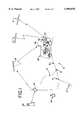
- FIG. 1is a schematic illustration of a method and system according to an embodiment of the present invention.
- FIG. 2illustrates an example of the differentially corrected GPS data stored in a file.
- FIG. 3illustrates schematically the electrical connections between the DGPS demodulator, the GPS receiver and the indicator.
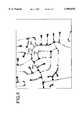
- FIG. 4illustrates the graphical representation of the differentially corrected GPS data.
- FIG. 5illustrates the graphical representation of nodes, segments and shape points.
- FIG. 6is a schematic illustration of a method and system according to an embodiment of the present invention.
- FIG. 7is a schematic illustration of a method and system according to an embodiment of the present invention.
- FIG. 1is a schematic illustration of a method and system according to an embodiment of the present invention for acquiring differentially corrected GPS data in real-time for forming a digital database of road geometry in a geographic region.
- a geographic region 10includes a plurality of roads 12 and intersections 14.
- the region 10is located such that it is possible to obtain standard GPS signals at most places in the region 10 from a constellation of GPS satellites 16. Further, in at least some and preferably most places in the region 10 it is possible to obtain DGPS correction signals from a DGPS satellite 18.
- the DGPS correction signalsmay be obtained from conventional, commercially-available sources. In one present embodiment John E. Chance & Associates, Inc. of Houston, Tex. commercially provides DGPS correction signals with its OmnistarTM DGPS.
- the OmnistarTM systemhas base stations 20 scattered at known sites on the coastal edge of the U.S. and a private geostationary satellite 18.
- the base stations 20provide DGPS correction signals to satellite 18 through an uplink 22 and the satellite 18 transmits the DGPS correction signals to earth.
- an on-road land-based vehicle 26such as an automobile is located in the geographic region 10 and is equipped with a receiver 28 for receiving GPS signals ("a GPS receiver”), a GPS antenna 34, a demodulator 32 for receiving differentially corrected GPS signals (“a DGPS demodulator”) and a DGPS antenna 30.
- the vehicleis also provided with an indicator 36 coupled to the demodulator 32 and a suitable computer readable medium 38 coupled to the receiver 28.
- the GPS receiver 28 and DGPS demodulator 32are coupled together so that each may communicate with the other.
- the land-based vehicle 26, equipped as shown,is used to acquire GPS data which will be differentially corrected in real-time and used to create a digital database of road geometry as the vehicle 26 is driven on road 12 in the geographic region 10.
- the GPS receiver 28 and DGPS demodulator 32are turned on so that the GPS receiver 28 receives GPS signals from the GPS satellites 16 through antenna 34 and the DGPS demodulator 32 receives DGPS signals from satellite 18 through antenna 30.
- the vehicle 26may be equipped with a GPS ProXL system available from Trimble Navigation Limited of Sunnyvale, Calif., and a DGPS demodulator, OmnistarTM Model 6300A available from John E. Chance & Associates, Inc. of Houston, Tex. While the GPS receiver 28 and DGPS demodulator 32 are illustrated as separate units, they may alternatively be combined as one unit, for example, by using Omnistar's Model 6300A-G which includes its own GPS receiver.
- the receiver 28 and the demodulator 32are both operated while the vehicle 26 is driven on roads 12 in the region 10.
- the GPS receiver 28obtains standard GPS data as it receives the GPS signals from satellite 16.
- the standard GPS dataindicates geographic locations of the vehicle 26 on the roads 12 (and also indicative of the locations of the roads 12 since the vehicle 26 is driven on the roads as the data is collected) as the vehicle 26 is driven in the geographic region 10.
- the standard GPS datais not indicative of the precise geographic position of the vehicle 26 because of the random errors that are intentionally induced in standard GPS signals.
- the receiver 28communicates its position, i.e.
- FIG. 2illustrates an example of the differentially corrected GPS data stored in file 42.
- a computer 33such as a laptop, is also provided in the vehicle 26 and the corrected GPS data stored in file 42 can be downloaded to the laptop's memory and stored therein until further processing as will be described hereinafter.
- the GPS receiver and DGPS demodulatorare preferably mounted in the trunk of the vehicle along with separate power supplies.
- the Omnistar DGPS demodulatorhas a display on the face of the unit that indicates that DGPS information is being received.
- indicator displayis out of view.
- indicator 36preferably in the form of an LED may be provided on the dashboard of the vehicle. The indicator 36 illuminates whenever the DGPS demodulator 32 is receiving DGPS signals. This allows the driver to keep his or her eyes forward on the road while visually confirming the reception of DGPS signals.
- two switchesare provided on the dashboard for the driver to turn on and off the GPS receiver 28 and DGPS demodulator 32 respectively without having to access the receiver and demodulator in the trunk.
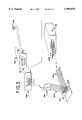
- FIG. 3illustrates schematically the electrical connections between the DGPS demodulator 32, the GPS receiver 28 and the indicator 36 located on the dashboard of the vehicle.
- a Y adapter 300having a 9 pin female connector 302 and two 9 conductor ribbon cables 304 attached thereto are connected to the RTCM OUT port located on the back panel of the DGPS demodulator 32.
- One ribbon cable 304is terminated by a 9 pin male connector 306 connected to the RTCM OUT port located on the back of the GPS receiver 28.
- the other ribbon cable 304terminates in a 9 pin male connector 308 connected to a 9 pin female connector 310.
- conductor 312 and 314are soldered to pins 2 and 5 of the female connector 310 and connected to the indicator 36 mounted on the dashboard of the vehicle.
- conductor 312carries the signal that DGPS signals are being received by the DGPS demodulator and conductor 314 carries signal ground.
- the differentially corrected GPS data stored in file 42are transmitted to a remote site where the data is further processed.
- the stored differentially corrected GPS dataare transferred to a remote site preferably using a file transfer protocol (FTP) software which compresses the data and allows it to be transmitted quickly.
- FTPfile transfer protocol
- the datamay alternatively be sent to the remote site by e-mail or on a floppy disk, for example.
- the datais converted to an ARC/INFO format using Environmental Systems Research Institute's software program. Once the conversion to ARC/INFO has been made, a data-technician can call up a graphical representation of the data on a workstation.
- FIG. 4illustrates the graphical representation of the differentially corrected GPS data displaying the portion of region 10 covered by the vehicle.
- a plurality of circles 400represent the differentially corrected GPS data collected.
- the datapoints 400are connected by lines according to the time each signal was received. From this graphical representation the data technician selects points on the display shown in FIG. 4 which will be designated as nodes which will become part of the digital database.
- nodesAs mentioned above, in a digital database of roadway geometry, a node represents a geographic endpoint of a segment. A segment, in turn, represents a portion of road between two nodes. Thus, each segment has a node at each end.
- the usercan also designate shape points 504 (see FIG. 5).
- Shape points 504are used to approximate the curvature of a segment between two nodes by requiring the segment to intersect the shape points as it extends between its endpoint nodes, as illustrated at segment 502 (FIG. 5).
- FIG. 5illustrates the display of the digital database where the nodes are indicated as square boxes 500, the segments are lines 502 and the shape points are circles 504.
- An advantage of using the OmnistarTM DGPS as part of the process of acquiring DGPS data,is that it provides extensive coverage (all 48 states, half of Canada, Mexico, Alaska along with portions of Caribbean and Guatemala). Also, the DGPS correction signals are real time, thereby eliminating post processing of the GPS data and the delay associated therewith.
- FIG. 6Another embodiment of the invention is illustrated in FIG. 6. Portions of this embodiment are similar to the first embodiment and like components are represented by the same numerals.
- a geographic area 110includes roads 112 and intersections 114.
- the base station 118includes a receiver that is adapted to receive GPS signals from a constellation of satellites 16.
- the base station 118is at a known surveyed site so that its precise position is known.
- an appropriate computing means 120compares the actual known position of the base station 118 to a position of the base station derived from the GPS signals received from the constellation of satellites. Since the signals from the constellation of satellites include induced errors, the induced errors can be determined by the computing means by a comparison of the actual position of the base station to its calculated position. Corrections can then be calculated.
- the correctionsare continuously calculated and values for the calculated corrections (Pseudo Range Corrections) are then continuously transmitted via a broadcast transmitter 122.
- the transmitter 122is an FM transmitter.
- a vehicle 26is driven on the roads 112 in the geographic area 100.
- the vehicleis equipped with a GPS receiver 28, as in the first embodiment.
- the vehicle 26is also equipped with a receiver 130, which is adapted to receive the signals broadcast from the transmitter 122.
- corrected positions for the vehicle 26 as it is being driven on the roads 112 in the region 100can be determined as in the first embodiment.
- a digital database of the roadway geometry in the regioncan be determined.
- This embodimentcan be used in a geographic areas in which an established base station broadcasts DGPS correction signals on a relatively continuous basis.
- the size of the geographic area that can be mapped in this manneris limited by the range of transmission of the FM transmitter.
- the distance from vehicle to the base stationbe limited so that the constellation of satellites for which the corrections are being broadcast by the transmitter 122 includes the same constellation of satellites used by the GPS receiver 28 in the vehicle 26.
- DCIDifferential Corrections, Inc.
- Cupertino, Calif.is a provider of DGPS corrections.
- DCIbroadcasts data over a network of FM radio stations.
- An advantage of DCI's systemis the cost for their service (about $600 a year).
- FIG. 7Another embodiment is shown in FIG. 7.
- a geographic region 400includes a plurality of roads 402 and intersections 403.
- the geographic region 400has a size such that a radius from approximately the center of the region 400 to an outer edge is less than approximately 100 miles.
- the region 400is located such that it is possible to obtain standard GPS signals at most places in the region 400.
- at least some places 404 in the region 400and in particular in at least portions of the region not more than approximately 100 miles from all other places in the region 400, it is possible to obtain DGPS correction signals.
- some or all of the region 400may be more than approximately 100 miles from an existing DGPS base station.
- a DGPS unit 410is moved into the region 400.
- the DGPS unit 410is moved to a location 405 which is one of the places 404 in the region where it is possible to obtain DGPS correction signals.
- the DGPS unit 410is a portable unit and is temporarily moved into the location 405 in the region 400.
- Located with the DGPS unit 410is a first standard GPS unit 416.
- the DGPS unit 410 and the first standard GPS unit 416are coupled together, in the manner described above, so that the geographic position of the location 405 can be obtained with relatively high precision.
- the geographic position of the location 405is determined within no more than approximately ⁇ 15 meters and, more preferably, the position can be determined within approximately ⁇ 5 meters, and most preferably within approximately ⁇ 3 meters.
- the DGPS unit 410 and the first standard GPS unit 416are located in a relatively secure location, such as a vehicle or a motel room.
- the DGPS unit 410may be removed or shut off, and then the first standard GPS unit 416 is continued to be operated at the location 405 for a period of time to obtain first standard GPS data 418.
- the period of timemay be any suitable period of time, such as continuously for 10 hours.
- the first standard GPS data 418indicate the geographic position of the location 405; however, these data 418 are not indicative of the precise geographic position of the location 405 because of the random errors that are intentionally induced in standard GPS signals.
- the first GPS unit 416may be operated automatically, i.e. without manual intervention.
- the standard GPS data 418 obtained by the first CPS unit 416 during the period of timeare stored in a suitable computer readable file 420 on a suitable computer readable medium 422 coupled to the first GPS unit 416.
- a second GPS unit 430is located in a mobile vehicle, such as an automobile 432.
- the mobile vehicleis of a type that can travel on the roadways 402 in the geographic area 400.
- the second GPS unit 430is operated to collect second data 440.
- the automobile 432is driven on the roadways 402 during at least some of the time that the second GPS unit 430 is collecting data.
- the data 440 obtained by the second CPS unit 430 in the vehicle 432 as the vehicle 432 is being driven on roadways 402 in the region 400are indicative of the locations of the vehicle 432 at various times during the period that the second GPS unit 430 is operating.
- the second data 440 collected by the second GPS unit 430are standard GPS data.
- the second GPS data 440 obtained by the second GPS unit 430 during the period of timeare stored in a second suitable computer readable file 442 on a second suitable computer readable medium 444 coupled to the second GPS unit 430.
- the first standard GPS data 418can be used to correct the second standard GPS data 440. Since the position of the first GPS unit 416 is known with precision (due to the initial use of the DGPS unit 410), the errors generated in the standard GPS data 418 can be precisely determined for all readings in the first data 418 during the period of time, using the known precise location 405 of the GPS unit 416 as a point of reference. Then, once the errors are determined, they can be used to generate corrections for the second GPS data 440 acquired during the same period of time by the second GPS unit 430 as it was being driven on the roadways 402.
- DGPS unit 410was only required to determine the corrected position of the GPS unit 416, it can thereafter be relocated to a second geographic region 400 and used in the same manner described above to allow the collection and correction of data in that other region using a GPS unit simultaneously with the data collection efforts in the first region 400.
- the first GPS unit 416 and the DGPS unit 410can be relocated after the precise location of the positions of the roadways 402 in the geographic region 400 are obtained.
- the first GPS unit 416 and the DGPS unit 410can be relocated to another geographic region and the positions of the roadways in the new geographic region can be obtained in a similar manner, as described above.
- An advantage of this embodimentis that cost of establishing a permanent DGPS base station is avoided.
- Another advantage of this embodimentis that it is suitable for use in regions where it is difficult to obtain continuous DGPS signals. For example, in mountainous regions or regions with many trees and other obstructions, it may be difficult to obtain a DGPS signal continuously from a satellite at many locations while the automobile is being driven on the roadways. In such locations, the present embodiment allows reliable, precise data to be obtained using only one DGPS signal obtained within a radius of approximately 100 miles.
Landscapes
- Engineering & Computer Science (AREA)
- Radar, Positioning & Navigation (AREA)
- Remote Sensing (AREA)
- Physics & Mathematics (AREA)
- General Physics & Mathematics (AREA)
- Computer Networks & Wireless Communication (AREA)
- Multimedia (AREA)
- Navigation (AREA)
- Position Fixing By Use Of Radio Waves (AREA)
Abstract
Description
Claims (43)
Priority Applications (1)
| Application Number | Priority Date | Filing Date | Title |
|---|---|---|---|
| US08/834,652US5999878A (en) | 1997-04-11 | 1997-04-11 | System and method for acquiring geographic data for forming a digital database of road geometry in a geographic region |
Applications Claiming Priority (1)
| Application Number | Priority Date | Filing Date | Title |
|---|---|---|---|
| US08/834,652US5999878A (en) | 1997-04-11 | 1997-04-11 | System and method for acquiring geographic data for forming a digital database of road geometry in a geographic region |
Publications (1)
| Publication Number | Publication Date |
|---|---|
| US5999878Atrue US5999878A (en) | 1999-12-07 |
Family
ID=25267462
Family Applications (1)
| Application Number | Title | Priority Date | Filing Date |
|---|---|---|---|
| US08/834,652Expired - LifetimeUS5999878A (en) | 1997-04-11 | 1997-04-11 | System and method for acquiring geographic data for forming a digital database of road geometry in a geographic region |
Country Status (1)
| Country | Link |
|---|---|
| US (1) | US5999878A (en) |
Cited By (53)
| Publication number | Priority date | Publication date | Assignee | Title |
|---|---|---|---|---|
| US6131069A (en)* | 1997-09-26 | 2000-10-10 | Claas Selbstfahrende Erntemaschinen Gmbh | Method for computer-aided mapping |
| US6169958B1 (en)* | 1999-04-09 | 2001-01-02 | Vsis, Inc. | Ionospheric correction for single frequency GPS receivers using three satellites |
| EP1046924A3 (en)* | 1999-04-19 | 2001-01-24 | Silicon Systems (UK) Limited | Positioning system |
| US6184821B1 (en)* | 1999-01-19 | 2001-02-06 | Ford Global Technologies, Inc. | On-board GPS sensors systems |
| US6208289B1 (en)* | 1999-05-14 | 2001-03-27 | Rockwell Collins, Inc. | System and method for monitoring and reporting GPS pseudo range correction data |
| US20010026270A1 (en)* | 2000-03-29 | 2001-10-04 | Higgins Darin Wayne | System and method for synchronizing raster and vector map images |
| US20010033290A1 (en)* | 2000-03-29 | 2001-10-25 | Scott Dan Martin | System and method for georeferencing digial raster maps |
| EP1162433A1 (en)* | 2000-06-08 | 2001-12-12 | Navigation Technologies Corporation | Method and system for obtaining user feedback regarding geographic data |
| WO2002001157A1 (en)* | 2000-06-23 | 2002-01-03 | Sportvision, Inc. | Locating an object using gps with additional data |
| US20020004701A1 (en)* | 2000-07-06 | 2002-01-10 | Pioneer Corporation And Increment P Corporation | Server, method and program for updating road information in map information providing system, and recording medium with program recording |
| US6385539B1 (en)* | 1999-08-13 | 2002-05-07 | Daimlerchrysler Ag | Method and system for autonomously developing or augmenting geographical databases by mining uncoordinated probe data |
| US6438491B1 (en) | 1999-08-06 | 2002-08-20 | Telanon, Inc. | Methods and apparatus for stationary object detection |
| US20020184236A1 (en)* | 2000-07-18 | 2002-12-05 | Max Donath | Real time high accuracy geospatial database for onboard intelligent vehicle applications |
| US6501501B1 (en)* | 1999-04-28 | 2002-12-31 | Aizudoken Co. Ltd. | Construction and civil engineering database generator and display |
| US6505106B1 (en)* | 1999-05-06 | 2003-01-07 | International Business Machines Corporation | Analysis and profiling of vehicle fleet data |
| US20030023614A1 (en)* | 2001-07-18 | 2003-01-30 | Newstrom Bryan J. | Populating geospatial database for onboard intelligent vehicle applications |
| US6550151B2 (en) | 2001-01-19 | 2003-04-22 | Donald R. Airey | Contour measuring device and method |
| KR20030067618A (en)* | 2003-07-21 | 2003-08-14 | 차기만 | A system for police-crime prevention cooperation investigation capable of a wireless, equipped with gps |
| US20030158667A1 (en)* | 2002-02-15 | 2003-08-21 | International Business Machines Corporation | Programmatically deriving street geometry from address data |
| US20040066376A1 (en)* | 2000-07-18 | 2004-04-08 | Max Donath | Mobility assist device |
| US6725553B2 (en) | 2001-01-19 | 2004-04-27 | Donald R. Airey | Contour measuring device and method |
| US20040139049A1 (en)* | 1996-08-22 | 2004-07-15 | Wgrs Licensing Company, Llc | Unified geographic database and method of creating, maintaining and using the same |
| EP1309878A4 (en)* | 2000-06-23 | 2005-01-05 | Sportvision Inc | Track model constraint for gps position |
| US6850841B1 (en) | 2003-05-15 | 2005-02-01 | Navtech North American, Llc | Method and system for obtaining lane data |
| US20050149251A1 (en)* | 2000-07-18 | 2005-07-07 | University Of Minnesota | Real time high accuracy geospatial database for onboard intelligent vehicle applications |
| US20050149259A1 (en)* | 1997-10-16 | 2005-07-07 | Kevin Cherveny | System and method for updating, enhancing, or refining a geographic database using feedback |
| US20050174257A1 (en)* | 2002-03-05 | 2005-08-11 | The University Of Minnesota | Intersection assistance system and method |
| US7038681B2 (en) | 2000-03-29 | 2006-05-02 | Sourceprose Corporation | System and method for georeferencing maps |
| US20060178793A1 (en)* | 2003-07-16 | 2006-08-10 | Carfax | System and method for generating vehicle history information |
| KR100730286B1 (en) | 2005-08-03 | 2007-06-19 | 가부시키가이샤 덴소 | Road map management system |
| EP1167924A3 (en)* | 2000-06-23 | 2008-05-14 | Navteq North America, LLC | Navigation system with feature for reporting errors |
| US20090222587A1 (en)* | 2008-02-28 | 2009-09-03 | Point-I Co., Ltd. | Providing location path |
| US20100106415A1 (en)* | 2008-10-28 | 2010-04-29 | Caterpillar Inc. | System and method for analyzing a route location |
| WO2010102681A1 (en)* | 2009-03-13 | 2010-09-16 | Nordnav Technologies Ab | Gnss receiver design testing |
| US20120179358A1 (en)* | 2007-09-07 | 2012-07-12 | On Time Systems, Inc. | System and method for automated updating of map information |
| US8340894B2 (en) | 2009-10-08 | 2012-12-25 | Honda Motor Co., Ltd. | Method of dynamic intersection mapping |
| US8369967B2 (en) | 1999-02-01 | 2013-02-05 | Hoffberg Steven M | Alarm system controller and a method for controlling an alarm system |
| US8618952B2 (en) | 2011-01-21 | 2013-12-31 | Honda Motor Co., Ltd. | Method of intersection identification for collision warning system |
| US8618951B2 (en) | 2010-09-17 | 2013-12-31 | Honda Motor Co., Ltd. | Traffic control database and distribution system |
| US20140074393A1 (en)* | 2011-03-03 | 2014-03-13 | Kabushiki Kaisha Toyota Chuo Kenkyusho | Local map generating device, local map generating system, global map generating device, global map generating system, and program |
| US8699800B1 (en)* | 2011-07-19 | 2014-04-15 | Google Inc. | User correction of pose for street-level images |
| US8725584B1 (en) | 2008-06-06 | 2014-05-13 | Carfax, Inc. | Tool for selling and purchasing vehicle history reports |
| US8818641B2 (en) | 2009-12-18 | 2014-08-26 | Honda Motor Co., Ltd. | Method of intersection estimation for a vehicle safety system |
| US8823556B2 (en) | 2010-09-02 | 2014-09-02 | Honda Motor Co., Ltd. | Method of estimating intersection control |
| US8892495B2 (en) | 1991-12-23 | 2014-11-18 | Blanding Hovenweep, Llc | Adaptive pattern recognition based controller apparatus and method and human-interface therefore |
| US9528834B2 (en) | 2013-11-01 | 2016-12-27 | Intelligent Technologies International, Inc. | Mapping techniques using probe vehicles |
| JP2017156108A (en)* | 2016-02-29 | 2017-09-07 | 株式会社神戸製鋼所 | Land form information collection system and land form information collection method |
| US20170350712A1 (en)* | 2016-06-03 | 2017-12-07 | Denso Corporation | Apparatus for identifying position of own vehicle and method for identifying position of own vehicle |
| US10083607B2 (en) | 2007-09-07 | 2018-09-25 | Green Driver, Inc. | Driver safety enhancement using intelligent traffic signals and GPS |
| US10198942B2 (en) | 2009-08-11 | 2019-02-05 | Connected Signals, Inc. | Traffic routing display system with multiple signal lookahead |
| US10311724B2 (en) | 2007-09-07 | 2019-06-04 | Connected Signals, Inc. | Network security system with application for driver safety system |
| US10361802B1 (en) | 1999-02-01 | 2019-07-23 | Blanding Hovenweep, Llc | Adaptive pattern recognition based control system and method |
| USD959552S1 (en) | 2021-07-21 | 2022-08-02 | Speedfind, Inc | Display sign |
Citations (35)
| Publication number | Priority date | Publication date | Assignee | Title |
|---|---|---|---|---|
| US32357A (en)* | 1861-05-21 | Device for hlviwa bees | ||
| US4428057A (en)* | 1981-06-09 | 1984-01-24 | Texas Instruments Incorporated | Electronic chart system |
| US4584646A (en)* | 1983-06-29 | 1986-04-22 | Harris Corporation | System for correlation and recognition of terrain elevation |
| US4590569A (en)* | 1983-10-14 | 1986-05-20 | Navigation Sciences Inc. | Navigation system including an integrated electronic chart display |
| USRE32357E (en) | 1979-04-27 | 1987-02-17 | Furuno Electric Co., Ltd. | Moving body track indicator system |
| US4731613A (en)* | 1984-12-07 | 1988-03-15 | Nissan Motor Company, Limited | Positioning system for a vehicle |
| US4743913A (en)* | 1986-02-19 | 1988-05-10 | Nissan Motor Company, Limited | Hybrid navigation system for determining a relative position and direction of a vehicle and method therefor |
| US4751512A (en)* | 1986-01-21 | 1988-06-14 | Oceanonics, Inc. | Differential navigation system for remote mobile users |
| US4791572A (en)* | 1985-11-20 | 1988-12-13 | Mets, Inc. | Method for accurately displaying positional information on a map |
| US4796190A (en)* | 1986-06-04 | 1989-01-03 | Cummings Elihu C | Navigation system |
| US4814711A (en)* | 1984-04-05 | 1989-03-21 | Deseret Research, Inc. | Survey system and method for real time collection and processing of geophysicals data using signals from a global positioning satellite network |
| US4815012A (en)* | 1986-02-05 | 1989-03-21 | Allied-Signal Inc. | Apparatus and method for real time reconstruction of digital map data |
| US4891761A (en)* | 1988-03-31 | 1990-01-02 | Mets, Inc. | Method for accurately updating positional information provided on a digital map |
| US4982332A (en)* | 1988-06-27 | 1991-01-01 | Pioneer Electronic Corporation | Road data generating method for use in an on-board navigation system |
| US4994974A (en)* | 1986-06-04 | 1991-02-19 | Cummings Elihu C | Touch sensitive navigation system |
| US5214757A (en)* | 1990-08-07 | 1993-05-25 | Georesearch, Inc. | Interactive automated mapping system |
| US5467282A (en)* | 1991-09-20 | 1995-11-14 | Dennis; Arthur R. | GPS and satellite navigation system |
| US5470233A (en)* | 1994-03-17 | 1995-11-28 | Arkenstone, Inc. | System and method for tracking a pedestrian |
| US5510798A (en)* | 1993-04-02 | 1996-04-23 | Bauer; William D. | Multiple-accuracy GPS system |
| US5517419A (en)* | 1993-07-22 | 1996-05-14 | Synectics Corporation | Advanced terrain mapping system |
| US5523761A (en)* | 1993-01-12 | 1996-06-04 | Trimble Navigation Limited | Differential GPS smart antenna device |
| US5528518A (en)* | 1994-10-25 | 1996-06-18 | Laser Technology, Inc. | System and method for collecting data used to form a geographic information system database |
| US5539645A (en)* | 1993-11-19 | 1996-07-23 | Philips Electronics North America Corporation | Traffic monitoring system with reduced communications requirements |
| US5557524A (en)* | 1991-10-18 | 1996-09-17 | Maki; Stanley C. | GPS/GLONASS travel recorder |
| US5563786A (en)* | 1994-02-16 | 1996-10-08 | Fuji Jukogyo Kabushiki Kaisha | Autonomous running control system for vehicle and the method thereof |
| US5563607A (en)* | 1994-05-26 | 1996-10-08 | Trimble Navigation Limited | Time and/or location tagging of an event |
| US5587715A (en)* | 1993-03-19 | 1996-12-24 | Gps Mobile, Inc. | Method and apparatus for tracking a moving object |
| US5589835A (en)* | 1994-12-20 | 1996-12-31 | Trimble Navigation Limited | Differential GPS receiver system linked by infrared signals |
| US5680140A (en)* | 1994-07-19 | 1997-10-21 | Trimble Navigation Limited | Post-processing of inverse differential corrections for SATPS mobile stations |
| US5699244A (en)* | 1994-03-07 | 1997-12-16 | Monsanto Company | Hand-held GUI PDA with GPS/DGPS receiver for collecting agronomic and GPS position data |
| US5760742A (en)* | 1995-05-12 | 1998-06-02 | Trimble Navigation Limited | Integrated mobile GIS/GPS/AVL with wireless messaging capability |
| US5764184A (en)* | 1997-03-10 | 1998-06-09 | Deere & Company | Method and system for post-processing differential global positioning system satellite positional data |
| US5852790A (en)* | 1996-04-22 | 1998-12-22 | Westinghouse Savannah River Company | Global positioning system recorder and method government rights |
| US5870689A (en)* | 1996-11-22 | 1999-02-09 | Case Corporation | Scouting system for an agricultural field |
| US5928306A (en)* | 1996-08-22 | 1999-07-27 | Trimble Navigation Limited | Method and apparatus for automated differential GPS processing |
- 1997
- 1997-04-11USUS08/834,652patent/US5999878A/ennot_activeExpired - Lifetime
Patent Citations (35)
| Publication number | Priority date | Publication date | Assignee | Title |
|---|---|---|---|---|
| US32357A (en)* | 1861-05-21 | Device for hlviwa bees | ||
| USRE32357E (en) | 1979-04-27 | 1987-02-17 | Furuno Electric Co., Ltd. | Moving body track indicator system |
| US4428057A (en)* | 1981-06-09 | 1984-01-24 | Texas Instruments Incorporated | Electronic chart system |
| US4584646A (en)* | 1983-06-29 | 1986-04-22 | Harris Corporation | System for correlation and recognition of terrain elevation |
| US4590569A (en)* | 1983-10-14 | 1986-05-20 | Navigation Sciences Inc. | Navigation system including an integrated electronic chart display |
| US4814711A (en)* | 1984-04-05 | 1989-03-21 | Deseret Research, Inc. | Survey system and method for real time collection and processing of geophysicals data using signals from a global positioning satellite network |
| US4731613A (en)* | 1984-12-07 | 1988-03-15 | Nissan Motor Company, Limited | Positioning system for a vehicle |
| US4791572A (en)* | 1985-11-20 | 1988-12-13 | Mets, Inc. | Method for accurately displaying positional information on a map |
| US4751512A (en)* | 1986-01-21 | 1988-06-14 | Oceanonics, Inc. | Differential navigation system for remote mobile users |
| US4815012A (en)* | 1986-02-05 | 1989-03-21 | Allied-Signal Inc. | Apparatus and method for real time reconstruction of digital map data |
| US4743913A (en)* | 1986-02-19 | 1988-05-10 | Nissan Motor Company, Limited | Hybrid navigation system for determining a relative position and direction of a vehicle and method therefor |
| US4796190A (en)* | 1986-06-04 | 1989-01-03 | Cummings Elihu C | Navigation system |
| US4994974A (en)* | 1986-06-04 | 1991-02-19 | Cummings Elihu C | Touch sensitive navigation system |
| US4891761A (en)* | 1988-03-31 | 1990-01-02 | Mets, Inc. | Method for accurately updating positional information provided on a digital map |
| US4982332A (en)* | 1988-06-27 | 1991-01-01 | Pioneer Electronic Corporation | Road data generating method for use in an on-board navigation system |
| US5214757A (en)* | 1990-08-07 | 1993-05-25 | Georesearch, Inc. | Interactive automated mapping system |
| US5467282A (en)* | 1991-09-20 | 1995-11-14 | Dennis; Arthur R. | GPS and satellite navigation system |
| US5557524A (en)* | 1991-10-18 | 1996-09-17 | Maki; Stanley C. | GPS/GLONASS travel recorder |
| US5523761A (en)* | 1993-01-12 | 1996-06-04 | Trimble Navigation Limited | Differential GPS smart antenna device |
| US5587715A (en)* | 1993-03-19 | 1996-12-24 | Gps Mobile, Inc. | Method and apparatus for tracking a moving object |
| US5510798A (en)* | 1993-04-02 | 1996-04-23 | Bauer; William D. | Multiple-accuracy GPS system |
| US5517419A (en)* | 1993-07-22 | 1996-05-14 | Synectics Corporation | Advanced terrain mapping system |
| US5539645A (en)* | 1993-11-19 | 1996-07-23 | Philips Electronics North America Corporation | Traffic monitoring system with reduced communications requirements |
| US5563786A (en)* | 1994-02-16 | 1996-10-08 | Fuji Jukogyo Kabushiki Kaisha | Autonomous running control system for vehicle and the method thereof |
| US5699244A (en)* | 1994-03-07 | 1997-12-16 | Monsanto Company | Hand-held GUI PDA with GPS/DGPS receiver for collecting agronomic and GPS position data |
| US5470233A (en)* | 1994-03-17 | 1995-11-28 | Arkenstone, Inc. | System and method for tracking a pedestrian |
| US5563607A (en)* | 1994-05-26 | 1996-10-08 | Trimble Navigation Limited | Time and/or location tagging of an event |
| US5680140A (en)* | 1994-07-19 | 1997-10-21 | Trimble Navigation Limited | Post-processing of inverse differential corrections for SATPS mobile stations |
| US5528518A (en)* | 1994-10-25 | 1996-06-18 | Laser Technology, Inc. | System and method for collecting data used to form a geographic information system database |
| US5589835A (en)* | 1994-12-20 | 1996-12-31 | Trimble Navigation Limited | Differential GPS receiver system linked by infrared signals |
| US5760742A (en)* | 1995-05-12 | 1998-06-02 | Trimble Navigation Limited | Integrated mobile GIS/GPS/AVL with wireless messaging capability |
| US5852790A (en)* | 1996-04-22 | 1998-12-22 | Westinghouse Savannah River Company | Global positioning system recorder and method government rights |
| US5928306A (en)* | 1996-08-22 | 1999-07-27 | Trimble Navigation Limited | Method and apparatus for automated differential GPS processing |
| US5870689A (en)* | 1996-11-22 | 1999-02-09 | Case Corporation | Scouting system for an agricultural field |
| US5764184A (en)* | 1997-03-10 | 1998-06-09 | Deere & Company | Method and system for post-processing differential global positioning system satellite positional data |
Non-Patent Citations (8)
| Title |
|---|
| "3-D Real Time Scanning," ARC News, p. 33, Winter, 1989. |
| "Precision Farming's `Garden` Grows in Midwest," GPS World, two pages, Apr., 1995. |
| 3 D Real Time Scanning, ARC News, p. 33, Winter, 1989.* |
| GEO Info Systems, pp. 25 26, Feb., 1997.* |
| GEO Info Systems, pp. 25-26, Feb., 1997. |
| Precision Farming s Garden Grows in Midwest, GPS World, two pages, Apr., 1995.* |
| W. Booth, "Weed-Whacking," Wired, pp. 160-164 and 215-216, Oct., 1996. |
| W. Booth, Weed Whacking, Wired, pp. 160 164 and 215 216, Oct., 1996.* |
Cited By (87)
| Publication number | Priority date | Publication date | Assignee | Title |
|---|---|---|---|---|
| US8892495B2 (en) | 1991-12-23 | 2014-11-18 | Blanding Hovenweep, Llc | Adaptive pattern recognition based controller apparatus and method and human-interface therefore |
| US20090077100A1 (en)* | 1996-08-22 | 2009-03-19 | Hancock S Lee | Unified geograhic database and methods of creating, maintaining and using the same |
| US20040139049A1 (en)* | 1996-08-22 | 2004-07-15 | Wgrs Licensing Company, Llc | Unified geographic database and method of creating, maintaining and using the same |
| US8935220B2 (en) | 1996-08-22 | 2015-01-13 | WGRS Licensing, LLC | Unified geographic database and method of creating, maintaining and using the same |
| US8112419B2 (en) | 1996-08-22 | 2012-02-07 | Wgrs Licensing Company, Llc | Unified geographic database and method of creating, maintaining and using the same |
| US6131069A (en)* | 1997-09-26 | 2000-10-10 | Claas Selbstfahrende Erntemaschinen Gmbh | Method for computer-aided mapping |
| US20050149259A1 (en)* | 1997-10-16 | 2005-07-07 | Kevin Cherveny | System and method for updating, enhancing, or refining a geographic database using feedback |
| US6184821B1 (en)* | 1999-01-19 | 2001-02-06 | Ford Global Technologies, Inc. | On-board GPS sensors systems |
| US8369967B2 (en) | 1999-02-01 | 2013-02-05 | Hoffberg Steven M | Alarm system controller and a method for controlling an alarm system |
| US10361802B1 (en) | 1999-02-01 | 2019-07-23 | Blanding Hovenweep, Llc | Adaptive pattern recognition based control system and method |
| US9535563B2 (en) | 1999-02-01 | 2017-01-03 | Blanding Hovenweep, Llc | Internet appliance system and method |
| US6169958B1 (en)* | 1999-04-09 | 2001-01-02 | Vsis, Inc. | Ionospheric correction for single frequency GPS receivers using three satellites |
| EP1046924A3 (en)* | 1999-04-19 | 2001-01-24 | Silicon Systems (UK) Limited | Positioning system |
| US6501501B1 (en)* | 1999-04-28 | 2002-12-31 | Aizudoken Co. Ltd. | Construction and civil engineering database generator and display |
| US6505106B1 (en)* | 1999-05-06 | 2003-01-07 | International Business Machines Corporation | Analysis and profiling of vehicle fleet data |
| US6208289B1 (en)* | 1999-05-14 | 2001-03-27 | Rockwell Collins, Inc. | System and method for monitoring and reporting GPS pseudo range correction data |
| US6832156B2 (en)* | 1999-08-06 | 2004-12-14 | Telanon, Inc. | Methods and apparatus for stationary object detection |
| US6438491B1 (en) | 1999-08-06 | 2002-08-20 | Telanon, Inc. | Methods and apparatus for stationary object detection |
| US6385539B1 (en)* | 1999-08-13 | 2002-05-07 | Daimlerchrysler Ag | Method and system for autonomously developing or augmenting geographical databases by mining uncoordinated probe data |
| US7038681B2 (en) | 2000-03-29 | 2006-05-02 | Sourceprose Corporation | System and method for georeferencing maps |
| US20010033290A1 (en)* | 2000-03-29 | 2001-10-25 | Scott Dan Martin | System and method for georeferencing digial raster maps |
| US7190377B2 (en) | 2000-03-29 | 2007-03-13 | Sourceprose Corporation | System and method for georeferencing digital raster maps with resistance to potential errors |
| US7167187B2 (en) | 2000-03-29 | 2007-01-23 | Sourceprose Corporation | System and method for georeferencing digital raster maps using a georeferencing function |
| US7161604B2 (en) | 2000-03-29 | 2007-01-09 | Sourceprose Corporation | System and method for synchronizing raster and vector map images |
| US7148898B1 (en) | 2000-03-29 | 2006-12-12 | Sourceprose Corporation | System and method for synchronizing raster and vector map images |
| US7142217B2 (en) | 2000-03-29 | 2006-11-28 | Sourceprose Corporation | System and method for synchronizing raster and vector map images |
| US20010026270A1 (en)* | 2000-03-29 | 2001-10-04 | Higgins Darin Wayne | System and method for synchronizing raster and vector map images |
| US20040186661A1 (en)* | 2000-06-08 | 2004-09-23 | Mark Barton | Method and system for obtaining user feedback regarding geographic data |
| EP1162433A1 (en)* | 2000-06-08 | 2001-12-12 | Navigation Technologies Corporation | Method and system for obtaining user feedback regarding geographic data |
| US6853905B2 (en) | 2000-06-08 | 2005-02-08 | Navteq North America, Llc | Method and system for obtaining user feedback regarding geographic data |
| EP2040038A1 (en) | 2000-06-08 | 2009-03-25 | Navteq North America, LLC | Method and system for obtaining user feedback regarding geographic data |
| US6718258B1 (en) | 2000-06-08 | 2004-04-06 | Navigation Technologies Corp | Method and system for obtaining user feedback regarding geographic data |
| EP1309878A4 (en)* | 2000-06-23 | 2005-01-05 | Sportvision Inc | Track model constraint for gps position |
| EP1167924A3 (en)* | 2000-06-23 | 2008-05-14 | Navteq North America, LLC | Navigation system with feature for reporting errors |
| US6657584B2 (en) | 2000-06-23 | 2003-12-02 | Sportvision, Inc. | Locating an object using GPS with additional data |
| WO2002001157A1 (en)* | 2000-06-23 | 2002-01-03 | Sportvision, Inc. | Locating an object using gps with additional data |
| US20020004701A1 (en)* | 2000-07-06 | 2002-01-10 | Pioneer Corporation And Increment P Corporation | Server, method and program for updating road information in map information providing system, and recording medium with program recording |
| EP1172632A1 (en) | 2000-07-06 | 2002-01-16 | Pioneer Corporation | Server, method and program for updating road information in map information providing system, and recording medium with program recorded |
| US7072764B2 (en) | 2000-07-18 | 2006-07-04 | University Of Minnesota | Real time high accuracy geospatial database for onboard intelligent vehicle applications |
| US20040066376A1 (en)* | 2000-07-18 | 2004-04-08 | Max Donath | Mobility assist device |
| US6977630B1 (en) | 2000-07-18 | 2005-12-20 | University Of Minnesota | Mobility assist device |
| US20020184236A1 (en)* | 2000-07-18 | 2002-12-05 | Max Donath | Real time high accuracy geospatial database for onboard intelligent vehicle applications |
| US20050149251A1 (en)* | 2000-07-18 | 2005-07-07 | University Of Minnesota | Real time high accuracy geospatial database for onboard intelligent vehicle applications |
| US6725553B2 (en) | 2001-01-19 | 2004-04-27 | Donald R. Airey | Contour measuring device and method |
| US6550151B2 (en) | 2001-01-19 | 2003-04-22 | Donald R. Airey | Contour measuring device and method |
| US20030023614A1 (en)* | 2001-07-18 | 2003-01-30 | Newstrom Bryan J. | Populating geospatial database for onboard intelligent vehicle applications |
| US7552008B2 (en) | 2001-07-18 | 2009-06-23 | Regents Of The University Of Minnesota | Populating geospatial database for onboard intelligent vehicle applications |
| US20030128182A1 (en)* | 2001-10-01 | 2003-07-10 | Max Donath | Virtual mirror |
| US7375728B2 (en) | 2001-10-01 | 2008-05-20 | University Of Minnesota | Virtual mirror |
| US20030158667A1 (en)* | 2002-02-15 | 2003-08-21 | International Business Machines Corporation | Programmatically deriving street geometry from address data |
| US6658356B2 (en)* | 2002-02-15 | 2003-12-02 | International Business Machines Corporation | Programmatically deriving street geometry from address data |
| US7209051B2 (en) | 2002-03-05 | 2007-04-24 | University Of Minnesota | Intersection assistance system and method |
| US20050174257A1 (en)* | 2002-03-05 | 2005-08-11 | The University Of Minnesota | Intersection assistance system and method |
| US6850841B1 (en) | 2003-05-15 | 2005-02-01 | Navtech North American, Llc | Method and system for obtaining lane data |
| US20060178793A1 (en)* | 2003-07-16 | 2006-08-10 | Carfax | System and method for generating vehicle history information |
| US7113853B2 (en)* | 2003-07-16 | 2006-09-26 | Carfax, Inc. | System and method for generating vehicle history information |
| KR20030067618A (en)* | 2003-07-21 | 2003-08-14 | 차기만 | A system for police-crime prevention cooperation investigation capable of a wireless, equipped with gps |
| KR100730286B1 (en) | 2005-08-03 | 2007-06-19 | 가부시키가이샤 덴소 | Road map management system |
| US10083607B2 (en) | 2007-09-07 | 2018-09-25 | Green Driver, Inc. | Driver safety enhancement using intelligent traffic signals and GPS |
| US20120179358A1 (en)* | 2007-09-07 | 2012-07-12 | On Time Systems, Inc. | System and method for automated updating of map information |
| US10311724B2 (en) | 2007-09-07 | 2019-06-04 | Connected Signals, Inc. | Network security system with application for driver safety system |
| US9043138B2 (en) | 2007-09-07 | 2015-05-26 | Green Driver, Inc. | System and method for automated updating of map information |
| US20090222587A1 (en)* | 2008-02-28 | 2009-09-03 | Point-I Co., Ltd. | Providing location path |
| US9741066B2 (en) | 2008-06-06 | 2017-08-22 | Carfax, Inc. | Tool for selling and purchasing vehicle history reports |
| US8725584B1 (en) | 2008-06-06 | 2014-05-13 | Carfax, Inc. | Tool for selling and purchasing vehicle history reports |
| US9646308B1 (en) | 2008-06-06 | 2017-05-09 | Carfax, Inc. | Tool for selling and purchasing vehicle history reports |
| US20100106415A1 (en)* | 2008-10-28 | 2010-04-29 | Caterpillar Inc. | System and method for analyzing a route location |
| US9360558B2 (en) | 2009-03-13 | 2016-06-07 | Alexander Mitelman | GNSS receiver design testing |
| WO2010102681A1 (en)* | 2009-03-13 | 2010-09-16 | Nordnav Technologies Ab | Gnss receiver design testing |
| US10198942B2 (en) | 2009-08-11 | 2019-02-05 | Connected Signals, Inc. | Traffic routing display system with multiple signal lookahead |
| US8340894B2 (en) | 2009-10-08 | 2012-12-25 | Honda Motor Co., Ltd. | Method of dynamic intersection mapping |
| US8903639B2 (en) | 2009-10-08 | 2014-12-02 | Honda Motor Co., Ltd. | Method of dynamic intersection mapping |
| US8818641B2 (en) | 2009-12-18 | 2014-08-26 | Honda Motor Co., Ltd. | Method of intersection estimation for a vehicle safety system |
| US9111448B2 (en) | 2010-09-02 | 2015-08-18 | Honda Motor Co., Ltd. | Warning system for a motor vehicle determining an estimated intersection control |
| US8823556B2 (en) | 2010-09-02 | 2014-09-02 | Honda Motor Co., Ltd. | Method of estimating intersection control |
| US8618951B2 (en) | 2010-09-17 | 2013-12-31 | Honda Motor Co., Ltd. | Traffic control database and distribution system |
| US8618952B2 (en) | 2011-01-21 | 2013-12-31 | Honda Motor Co., Ltd. | Method of intersection identification for collision warning system |
| US9103680B2 (en)* | 2011-03-03 | 2015-08-11 | Kabushiki Kaisha Toyota Chuo Kenkyusho | Local map generating device, local map generating system, global map generating device, global map generating system, and program |
| US20140074393A1 (en)* | 2011-03-03 | 2014-03-13 | Kabushiki Kaisha Toyota Chuo Kenkyusho | Local map generating device, local map generating system, global map generating device, global map generating system, and program |
| US8965040B1 (en) | 2011-07-19 | 2015-02-24 | Google Inc. | User correction of pose for street-level images |
| US8699800B1 (en)* | 2011-07-19 | 2014-04-15 | Google Inc. | User correction of pose for street-level images |
| US9528834B2 (en) | 2013-11-01 | 2016-12-27 | Intelligent Technologies International, Inc. | Mapping techniques using probe vehicles |
| JP2017156108A (en)* | 2016-02-29 | 2017-09-07 | 株式会社神戸製鋼所 | Land form information collection system and land form information collection method |
| US20170350712A1 (en)* | 2016-06-03 | 2017-12-07 | Denso Corporation | Apparatus for identifying position of own vehicle and method for identifying position of own vehicle |
| US10480949B2 (en)* | 2016-06-03 | 2019-11-19 | Denso Corporation | Apparatus for identifying position of own vehicle and method for identifying position of own vehicle |
| USD959552S1 (en) | 2021-07-21 | 2022-08-02 | Speedfind, Inc | Display sign |
| USD1013783S1 (en) | 2021-07-21 | 2024-02-06 | Speedfind, Inc. | Display sign |
Similar Documents
| Publication | Publication Date | Title |
|---|---|---|
| US5999878A (en) | System and method for acquiring geographic data for forming a digital database of road geometry in a geographic region | |
| US5689252A (en) | Navigation system for an automotive vehicle | |
| Zito et al. | Global positioning systems in the time domain: How useful a tool for intelligent vehicle-highway systems? | |
| Wolf et al. | Accuracy issues with route choice data collection by using global positioning system | |
| US6333703B1 (en) | Automated traffic mapping using sampling and analysis | |
| JP4938172B2 (en) | Method and system for using altitude information in a satellite positioning system | |
| US20210199437A1 (en) | Vehicular component control using maps | |
| JP3572161B2 (en) | Man location system and current position estimation method | |
| EP1357358A1 (en) | Navigation device with central server | |
| JP2001509883A (en) | Navigation system using GPS data | |
| Du et al. | Lane-level positioning for in-vehicle navigation and automated vehicle location (AVL) systems | |
| US20030083810A1 (en) | Method of providing vehicle instructions to a non-navigable point of interest | |
| JP2000348297A (en) | Mobile terminal device, service center, and position information detection display system | |
| US6324468B1 (en) | Process for transmitting route information which concerns a route of a vehicle in a road network between a traffic information center and a terminal in a vehicle, traffic information center and terminal | |
| JP4652097B2 (en) | Altitude calculation device and navigation device | |
| KR20220019641A (en) | Proximity-based navigation method | |
| US12072431B2 (en) | Position specifying system for mobile object and mobile object used for the position specifying system | |
| Fix et al. | Global positioning system: an effective way to map a small area or catchment | |
| WO2011160731A1 (en) | An electronic map creation process | |
| CN113727434B (en) | Vehicle-road cooperative auxiliary positioning system and method based on edge computing gateway | |
| Meng et al. | Development of satellite based positioning and navigation facilities for precise ITS applications | |
| JP3719185B2 (en) | Road mapping apparatus and program | |
| KR100547623B1 (en) | Precise positioning device and method using location information of radio frequency recognition system | |
| Dailey et al. | Automatic Transit Location System | |
| Lloret | Inertial+ total station+ GPS for high productivity surveying |
Legal Events
| Date | Code | Title | Description |
|---|---|---|---|
| AS | Assignment | Owner name:NAVIGATION TECHNOLOGIES NORTH AMERICA, INC., CALIF Free format text:ASSIGNMENT OF ASSIGNORS INTEREST;ASSIGNORS:HANSON, JOHN L.;SHOTZ, ROBERT H.;REEL/FRAME:009042/0089;SIGNING DATES FROM 19980303 TO 19980310 | |
| AS | Assignment | Owner name:NAVIGATION TECHNOLOGIES CORPORATION, ILLINOIS Free format text:ASSIGNMENT OF ASSIGNORS INTEREST;ASSIGNOR:NAVIGATION TECHNOLOGIES NORTH AMERICA, INC.;REEL/FRAME:009126/0783 Effective date:19980331 | |
| STCF | Information on status: patent grant | Free format text:PATENTED CASE | |
| FPAY | Fee payment | Year of fee payment:4 | |
| AS | Assignment | Owner name:NAVTEQ CORPORATION, ILLINOIS Free format text:ASSIGNMENT OF ASSIGNORS INTEREST;ASSIGNOR:NAVIGATION TECHNOLOGIES CORPORATION;REEL/FRAME:015293/0400 Effective date:20040203 Owner name:NAVTEQ NORTH AMERICA LLC, ILLINOIS Free format text:ASSIGNMENT OF ASSIGNORS INTEREST;ASSIGNOR:NAVTEQ CORPORATION;REEL/FRAME:015286/0504 Effective date:20040510 Owner name:NAVTEQ NORTH AMERICA LLC,ILLINOIS Free format text:ASSIGNMENT OF ASSIGNORS INTEREST;ASSIGNOR:NAVTEQ CORPORATION;REEL/FRAME:015286/0504 Effective date:20040510 Owner name:NAVTEQ CORPORATION,ILLINOIS Free format text:ASSIGNMENT OF ASSIGNORS INTEREST;ASSIGNOR:NAVIGATION TECHNOLOGIES CORPORATION;REEL/FRAME:015293/0400 Effective date:20040203 | |
| FPAY | Fee payment | Year of fee payment:8 | |
| FPAY | Fee payment | Year of fee payment:12 | |
| AS | Assignment | Owner name:NAVTEQ B.V., NETHERLANDS Free format text:ASSIGNMENT OF ASSIGNORS INTEREST;ASSIGNOR:NAVTEQ NORTH AMERICA, LLC;REEL/FRAME:027588/0051 Effective date:20111229 | |
| AS | Assignment | Owner name:HERE GLOBAL B.V., NETHERLANDS Free format text:CHANGE OF NAME;ASSIGNOR:NAVTEQ B.V.;REEL/FRAME:033830/0681 Effective date:20130423 |