US5999837A - Localizing and orienting probe for view devices - Google Patents
Localizing and orienting probe for view devicesDownload PDFInfo
- Publication number
- US5999837A US5999837AUS08/938,209US93820997AUS5999837AUS 5999837 AUS5999837 AUS 5999837AUS 93820997 AUS93820997 AUS 93820997AUS 5999837 AUS5999837 AUS 5999837A
- Authority
- US
- United States
- Prior art keywords
- target
- microscope
- signaling devices
- handle
- surgical
- Prior art date
- Legal status (The legal status is an assumption and is not a legal conclusion. Google has not performed a legal analysis and makes no representation as to the accuracy of the status listed.)
- Expired - Lifetime
Links
Images


Classifications
- G—PHYSICS
- G02—OPTICS
- G02B—OPTICAL ELEMENTS, SYSTEMS OR APPARATUS
- G02B21/00—Microscopes
- G02B21/0004—Microscopes specially adapted for specific applications
- G02B21/0012—Surgical microscopes
- A—HUMAN NECESSITIES
- A61—MEDICAL OR VETERINARY SCIENCE; HYGIENE
- A61B—DIAGNOSIS; SURGERY; IDENTIFICATION
- A61B90/00—Instruments, implements or accessories specially adapted for surgery or diagnosis and not covered by any of the groups A61B1/00 - A61B50/00, e.g. for luxation treatment or for protecting wound edges
- A61B90/20—Surgical microscopes characterised by non-optical aspects
- A—HUMAN NECESSITIES
- A61—MEDICAL OR VETERINARY SCIENCE; HYGIENE
- A61B—DIAGNOSIS; SURGERY; IDENTIFICATION
- A61B90/00—Instruments, implements or accessories specially adapted for surgery or diagnosis and not covered by any of the groups A61B1/00 - A61B50/00, e.g. for luxation treatment or for protecting wound edges
- A61B90/39—Markers, e.g. radio-opaque or breast lesions markers
- A61B2090/3937—Visible markers
- A61B2090/3945—Active visible markers, e.g. light emitting diodes
- A—HUMAN NECESSITIES
- A61—MEDICAL OR VETERINARY SCIENCE; HYGIENE
- A61B—DIAGNOSIS; SURGERY; IDENTIFICATION
- A61B90/00—Instruments, implements or accessories specially adapted for surgery or diagnosis and not covered by any of the groups A61B1/00 - A61B50/00, e.g. for luxation treatment or for protecting wound edges
- A61B90/39—Markers, e.g. radio-opaque or breast lesions markers
- A61B2090/3983—Reference marker arrangements for use with image guided surgery
Definitions
- the present inventionrelates to the medical diagnostic and surgical arts. More particularly the present invention relates to a microscope calibrator probe for calibrating and verifying calibration of a microscope used in conjunction with various medical procedures including neurosurgery, neurobiopsy, CT-table needle body biopsy, breast biopsy, endoscopic procedures, orthopedic surgery, and the like.
- Three-dimensional diagnostic images of the brain, spinal cord, and other body portionsare produced by diagnostic imaging equipment such as CT scanners, magnetic resonance imagers, and the like. These imaging modalities often provide structural detail with a resolution of a millimeter or better.
- Image guided surgery systemshave been developed to utilize this data to assist the surgeon in presurgical planning and in accurately locating a region of interest within the body of a patient.
- the image guided surgery systemsare used to display position and orientation of a surgical tool in its correct location with respect to the images of the patient.
- One example of an image guided surgery systemis U.S. Pat. No. 5,517,990, Stereotaxy Wand and Tool Guide, to Kalfas et al. issued May 21, 1996, incorporated by reference herein.
- a high powered surgical microscopeis often utilized.
- a microscopemay, for instance, be used to see blood vessels or other microscopic details within the patient.
- the microscopeis supported by a movable electronic support structure which may be rolled along the ground or mounted to a ceiling or a wall, for example. Controls adjacent the microscope on the support structure allow the surgeon to manually or electronically position the microscope over the patient's body at a desired location.
- a series of position signaling devicessuch as infrared emitters or reflectors are typically secured to the microscope at some location.
- the position signaling devicesare tracked by a localizer located within the surgical room capable of sensing the position signaling devices.
- the image guided surgery systemuses this data to provide the surgeon with an indication of the position and orientation of the microscope with respect to patient data and images.
- calibrating views seen through a microscope with respect to images displayed on a monitoris often a nuisance. For instance, often times a surgeon is able to find a region of interest without aid of a monitor tracking the position of the microscope and thus the surgeon would prefer if he or she were able to simply verify a location and orientation of the microscope once the region of interest is sighted. Further, in situations where a microscope is not tracked by virtue of position signaling devices, determining the precise positioning of an object in view with respect to images shown on the monitor becomes extemely difficult.
- the present inventionprovides a new and improved method and apparatus for calibrating and verifying calibration of a surgical microscope which addresses the above-referenced matters, and others.
- a microscope calibrator probeincludes a handle, a tool head connected to the handle, a viewable target connected to an end of the tool head opposite the handle, and three or more position signaling devices disposed on the handle for tracking the probe in an image guided surgery system.
- the handleincludes three or more position signaling devices on each of a front side and rear side of the handle to accommodate both right and left handed users.
- the tool headincludes a bend of approximately 90 degrees to provide easy placement of the viewable target on an object being viewed below a microscope. Other angles for the bend are also acceptable.
- a precise location of the object being viewedis determined by sensing a location the three or more position signaling devices disposed on the handle with respect to the operating room and knowing an offset between the position signaling devices and a bottom surface of the viewable target in contact with the object.
- the viewable targetalso includes a viewing aperture for calibrating a line of sight of the microscope. More specifically, by aligning the microscope with an axis of the viewable aperture such that a clear, unobstructed view through the viewable aperture is achieved, a position of the probe can be sensed and translated to a current line of sight of the microscope. Additionally, the viewable target also may include a means for indicating a rotational sense of the viewable target.
- the means for indicatingmay be a marking on a top face of the viewable target.
- the means for indicating the rotational senseis aligned with a view through the microscope to allow a surgeon to set a desired rotational sense of the microscope with respect to images shown on monitors.
- An apparatus for determining an attribute of a microscopeincluding a target alignable along a focal axis of the microscope, and a plurality of position signaling devices having a known relationship to the target.
- a system for determining an attribute of a microscopeincluding a tool, a means for tracking the plurality of position signaling devices, and a means for processing information tracked by the means for tracking.
- the toolincludes a tool head, a means for supporting the tool head, a viewable target coupled to an end of the tool head, and a plurality of position signaling devices having a known relationship to the viewable target.
- a method of determining an attribute of a microscopeincludes the steps of focusing the microscope on an object in a field of view of the microscope, positioning a target on the object in the field of view, and sensing the position of the target in relation to the microscope.
- a method of determining an attribute of a microscope in an image guided surgery systemincludes the steps of focusing the microscope on a viewable target which has a means for indicating a rotational sense of the viewable target, positioning the viewable target such that the means for indicating the rotational sense of the viewable target is aligned with a desired rotational sense of the microscope, and using the image guided surgery system to determine a position of the position signaling device.
- FIG. 1is a perspective view of an operating room in which the present invention is deployed
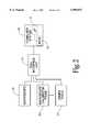
- FIG. 2is a block diagram of a system according to the present invention.
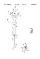
- FIG. 3is a front view of a microscope calibrator probe of the present invention.
- FIG. 4is a back view of the microscope calibrator probe of FIG. 3.
- a patient(not shown) is received on an operating table or other subject support 10 and appropriately positioned within an operating or surgical room 12.
- a securing meanssuch as a head clamp 16 securely positions a portion of the patient or subject under consideration.
- a locating device 20such as an infrared localizer determines the location and orientation of at least one surgical tool. Tools refers to any instrument or apparatus in the surgical room which is tracked by the locating device 20.
- the locating device 20is an infrared localizer such as the PolarisTM localizer system supplied by Northern Digital, Inc. of Waterloo, Ontario, Canada.
- the localizer systemincludes two spaced apart infrared cameras 22 mounted on a sensor head 24.
- the sensor head 24is in turn mounted in a fixed position within the operating room 12, for example on a stand 26 resting on the floor.
- the cameras 22may be mounted in another known position in the operating room 12, such as to the ceiling or wall or to the subject support 10.
- other locating devicessuch as ultrasonic, optical, RF, or electromagnetic localizers, may be used.
- the surgical toolmay also be mounted to an articulated arm, the arm functioning as the locating device.
- a surgical microscope 35aids a surgeon in viewing microscopic images of the patient while conducting a procedure or surgery.
- the surgeonviews the images through a viewing piece 52 of the microscope 35.
- the viewing piece 52may include cross hairs or other markings to aid the surgeon with calibrating a rotational sense of the microscope 35 with respect to images shown on monitors such as overhead monitors 31.
- the microscope 35is supported by a microscope support structure 37 which is situated on the floor.
- the microscope support structure 37includes several movable joints 38 which may be manually or electronically controlled to position the microscope 35 in a desired location. For instance, control buttons 39 attached to a handle 41 of the microscope 35 may be used to accurately and precisely locate the microscope 35 in the operating room 12.
- a reference frame target(not shown) including three or more position signaling device is rigidly attached to the microscope 35.
- the position signaling devicesmay, for instance, be infrared emitters, sonic emitters, RF emitters, or reflectors depending on the type of locating device 20 in the operating room 12.
- the reference frame targetprovides a means for the locating device 20 to accurately track a positioning of the microscope 35 with respect to the operating room 12.
- the microscope support structure 37is shown to be situated on the ground, it will be appreciated that the microscope support structure could alternatively be attached to the ceiling or to a wall. Of course, the microscope 35 could be supported by any other suitable mechanism.
- the microscope 35may be designed to have a fixed or variable focal distance. In the event the focal distance is fixed, the microscope 35 must be physically positioned by the surgeon to focus in on an object of interest.
- the surgeonmay be able to keep the microscope 35 fixed in a physical location, while varying the focusing distance of a microscope lens to a desired distance.
- the focusing distance of the microscope 35may be precalibrated and the microscope 35 may come equipped with a signaling device or other means for indicating to the surgeon the current focusing distance of the microscope lens.
- a surgical microscope calibrator probe 50is located in the operating room 12. As will be discussed in more detail below, the microscope calibrator probe 50 provides a means for rapidly and accurately calibrating and verifying the calibration of the microscope 35.
- an operator console 28supports a computer system 30.
- the computer system 30can be remotely located and connected with the operator console 28 by cabling.
- the computer system 30includes a processor 32 and a data memory 34 coupled to the processor 32.
- the data memory 34contains data indicative of a three-dimensional image of the patient or subject. Because the data can be visualized as a three-dimensional rectangular grid, selectable orthogonal and other oblique planes of the data can be readily withdrawn from the data memory 34 using conventional technology. Such data may be displayed on the overhead monitor 31 in the operating room 12 for convenient viewing by the surgeon.
- the microscope 35, the microscope calibrator probe 50, and other tools 49are coupled to the computer system 30 through a tool interface unit 53.
- the tool interface unit 53serves to interface the computer system 30 with all the tools in the operating room 12.
- Each tool in the operating roompasses along information related to its local reference frame to the tool interface unit 53.
- the local reference frame for the microscope calibrator probe 50may be defined such that an origin is at some desirable location associated with the microscope calibrator probe 50.
- the location and orientation of the microscope calibrator probe 50 and hence the local reference frame with respect to the cameras 22 and hence the operating room reference frameare determined.
- the relationship between the local reference frames of the other tools and the operating room reference framemay be determined.
- transforms between the patient, tools and operating room reference framescan readily be calculated.
- a transformis accomplished by determining an offset x offset , y offset , z offset between the reference frames to be transformed. These values of x offset , y offset , z offset are added to or subtracted from the coordinates of one of the reference frames as required to translate between the two. The coordinate systems are then rotated relative to each other about their origins by angles ⁇ , ⁇ , ⁇ so that their respective x, y and z axes coincide.
- the microscope calibrator probe 50includes a handle 55 and a tool head which in the present embodiment is shaft 60.
- An end of the shaft 60 closest the handle 55includes a threaded connector 64 and screw head 65 for securing the shaft 60 to the handle 55.
- the screw head 65is shaped with a two or more flat sides 68 to allow a wrench or other tool to aid in securing the threaded connector 64 to the handle 55.
- An end of the handle 55 closest the shaft 60includes a corresponding threaded aperture 72 for receiving the screw head 64.
- the threaded aperture 72is sized to ensure a secure threaded fit is made with the threaded connector 64. Glue or other adhesive material may be provided within the threaded aperture 72 to aid in securing the shaft 60 to the handle 55 in a desirable position.
- the handle 55includes a series of position signaling devices 75a, 75b, 75c, collectively referred to as position signaling devices 75, disposed on a front side 77 of the probe 50 as shown in FIG. 3.
- the handle 55also includes a series of position signaling devices 80a, 80b, 80c, collectively referred to as position signaling devices 80, disposed on a rear side 82 of the probe 50 as shown in FIG. 4.
- the location of position signaling devices 75 and position signaling devices 80are such that planes defined by each of the respective position signaling devices 75, 80 are substantially parallel to one another.
- the position signaling devices 75, 80 of the preferred embodimentare infrared emitters such as light emitting diodes.
- position signaling devicessuch as reflectors, sonic emitters, and RF emitters could alternatively be used. It will also be appreciated that additional position signaling devices could be used to serve as a backup in the event one or more of the existing position signaling devices 75,80 fail or become out of sight or range of the cameras 22.
- the shaft 60includes a bend 85 and a viewable target 90 connected to an end of the shaft 60 furthest from the handle 55.
- the bend 85 in the present embodimentis shown to be at a 90 degree angle, although any suitable angle, or no angle at all, could be selected.
- the target 90includes an aperture 92 for receiving and rigidly securing to the shaft 60. More specifically, a diameter of the aperture 92 is such that the shaft 60 frictionally press fits within the aperture thereby providing a non-rotating, rigid connection between the shaft 60 and the target 90.
- the targetis shown to be rectangular in shape and has dimensions of a height H, width W and length L.
- the length L and width W of the target 90are sized so that the target can readily be inserted into relatively small areas being viewed within the patient through the microscope 25.
- the length Lis 8 mm and the width W is 6 mm.
- the height H of the target 90is also relatively small in size so as to fit within small regions being viewed, however is tall enough to ensure that a line of sight of the microscope 35 may be properly calibrated as is discussed in more detail below.
- the heightis 6 mm.
- the target 90 of the present embodimentis rectangular in shape, the target 90 could take any shape.
- the target 90could be spherical, triangular, hexagonal, cylindrical, oval, etc.
- the target 90is shown to include a viewing aperture 95 which defines a viewing axis A1.
- the viewing axis A1 (FIG. 4) of the viewing aperture 95is substantially parallel to the planes formed by the position signaling devices 75 and the position signaling devices 80.
- the viewing aperture 95 of the present embodimenthas a diameter of 2 mm, however any suitable size aperture may be selected as is discussed in more detail below.
- the targetfurther includes a top surface 108 and a bottom surface 110. Planes defined by both the top surface 108 and bottom surface 110 are substantially orthogonal to the axis A1 and to the planes defined by the position signaling devices 75, 80, respectively.
- the target 90includes a means for indicating a rotational sense of the target 90.
- the means for indicating the rotational sense of the targetis an indicator mark 112 drawn on the top surface 108 of the target 90.
- Other means for indicating a rotational sensesuch as placing a notch on the top surface 108 of the target 90 or shaping the target 90 to have a pointed edge, etc. could also be used.
- the targetis made of stainless steel, however, it will be appreciated that any other durable material including, but not limited to, plastic, wood, rubber, and other metals could be used.
- a memory 100 disposed in the handle 53couples to the tool interface unit 55 via a seven pin female connector 102 and cord 104.
- the memory 100stores and supplies the tool interface unit 53 with information related to the positioning of the position signaling devices 75, 80 with respect to the local reference frame of the probe. Further, the memory 100 stores and supplies to the tool interface unit 53 a three dimensional offset between the plane defined by a bottom surface 108 of the target 90 and a selected point with respect to each of the position signaling devices 75, 80.
- the selected points of the present embodimentare points B and C located at a center of position signaling devices 75a, 80a, respectively (see FIGS. 3 and 4). It will be appreciated, however, that any point could have been selected.
- the memory 100stores in the memory 100 a location of a top surface 108 of the target with respect to points B and C. As can be seen, once a location of either the top surface 108 or bottom surface 108 is known, the location of the other can be readily calculated based on knowing the height H of the target 90.
- the memory 100also stores offset values between points B and C and the axis A1 of the viewing aperture 95.
- Determining attributes of the microscope 35includes calibrating or determining a focusing distance of the microscope lens such that a center of a depth of field can be determined, calibrating or determining a rotational sense of the microscope such that images seen at the top, bottom, left and right of the microscope viewing field correspond to the orientation of an image on the viewable monitor, and calibrating or determining a line of sight or barrel sight of the microscope with respect to the surgical room.
- the microscope calibrator probe 50 of the present inventionis able to calibrate, determine and verify calibration of the microscope 35 with respect to any and all of the above in a simple and easy manner.
- a surgeoninitially situates the microscope 35 above a region to be viewed and focuses the microscope on an object of interest. Often times the surgeon is able to locate the object of interest with the microscope without aid of the image guided surgery system. Thus, precalibrating the microscope 35 using a known calibration method is not always necessary.
- the surgeonplaces the bottom surface 108 of the target 90 of the microscope calibrator probe 50 on top of the object. As the shaft 60 of the probe 50 includes bend 85, the surgeon is typically able to reach the object without obstructing a view from the microscope 35 or otherwise needing to reorient the microscope 35 with respect to the object.
- the shaft 60did not include the bend 85, it would likely be difficult to position the target 90 to the desired location as the handle 55 of the probe 50 would not easily fit underneath the microscope 35 while still being able to focus the microscope 35 on the object.
- the surgeonis able to calibrate the focusing distance of the microscope 35. More specifically, by entering a calibrate command to the computer system 30, the cameras 22 sense a location of the probe 50 through position signaling devices 75 or 80, whichever is in a line of sight with the camera 22. Next, using stored offset information between the position signaling devices 78 and 80 as stored in memory 100, the computer system 30 determines the location of the bottom surface 110 of the target 90 with respect to the operating room.
- a distance between a point intersecting axis A1 on the bottom surface 110 of the target 90 and a sensed location of the microscope 35is determined. Based on this information, an approximate location in which the microscope 35 is currently focused is determined and the focusing distance of the microscope 35 is calibrated. If an exact location in which the microscope 35 is currently focused is desired, the user must ensure that the object of interest underneath the target 90 is also intersected by the axis A1 of the viewing aperture 95. This may, for instance, be accomplished by viewing the object through the aperture 95 with the microscope 35 prior to calibrating the location of the object.
- the surgeonmay optionally calibrate or verify a line of sight of the microscope 35. Calibration of the line of sight is accomplished by viewing the object through the viewing aperture 95 of target 90. More specifically, the surgeon positions the probe 50 until he or she is able to see directly down the axis A1 of the viewing aperture 95. The surgeon is able to determine if alignment of the microscope 35 and the viewing aperture 95 is properly made by determining whether any part of an inner wall of the viewing aperture 95 is seen through the microscope 35. If portions of the inner wall of the viewing aperture 95 are seen, the surgeon must realign the probe 35 until a clear, unobstructed view of the object through the viewing aperture 95 is visible.
- the surgeon or other individualinputs a command to the computer system 30 to calibrate the line of sight of the microscope 35. Based on the sensed position of the microscope 35 and the probe 50, the current line of sight of the microscope 35 is calibrated.
- a diameter of the viewing aperture 95 and height of the targetshould be sized to accommodate the magnification power of microscope 35 being calibrated. If, for instance, very slight movements of the target cause complete loss of view through the viewing aperture, the diameter of the viewing aperture 95 should be increased or height H of the target 90 should be reduced to accommodate such slight human movements in handling the probe 50.
- the microscope 35may not include position signaling devices attached thereto and thus is not tracked in the operating room.
- the present inventionnevertheless provides a manner in which both the exact focusing distance of the microscope and the line of sight of the microscope may be calibrated at any given location.
- a rotational sense of the microscope 35may also be optionally calibrated or verified with use of the probe 50.
- the surgeonaligns the indicator mark 112 on target 90 with a desired marking (such as a top cross hair) seen through the viewing piece 52 (FIG. 1) of the microscope 35.
- a desired markingsuch as a top cross hair
- the surgeon or other individualinputs a command to the computer system 30 indicating that a rotational sense of the microscope 35 is being calibrated.
- the direction in which the indicator mark 112 is pointing with respect to the operating room 12is taken to be a top direction for an image displayed on a monitor such as overhead monitors 31.
- the displayed imagesmay later be rotated in conjunction with sensed movements of the microscope 35 in the operating room 12.
- the probe 50may also be used independent of the microscope 35 to indicate to the computer system 30 which portion of an image the surgeon prefers to have at the top of the viewable monitors 31. For instance, if a patients head is currently displayed on the monitors 31 with a top portion of the head situated at the top of the viewable monitor 31, the surgeon may point the top indicator mark 112 of the probe 50 to the left or right of the patient's body and enter a command to the computer system 30 to rotate the image on the screen by 90 degrees. It is, of course, possible to do some or all of the above calibrations simultaneously and enter a single command to the computer system 30.
- position and orientation of the position signaling devices 75, 80 of the present inventionserve several purposes.
- One reason for providing position signaling devices 75, 80 on both the front side 77 and back side 82 of the probeis to accommodate both left and right handed individuals.
- having position signaling devices 75, 80 on both sides of the probe 50allows more flexibility in using the probe 50 without worry of losing a line of sight between the probe 50 and cameras 22. Because the planes defined by each of the position signaling devices 75, 80 are substantially parallel and the position signaling devices 75,80 are facing opposite directions, the cameras 22 tracking the probe 50 only sense one of the two position signaling devices 75,80 at any given time.
- the planes defined by the position signaling device 75, 80are substantially parallel to the viewing axis A1 and, in the preferred embodiment, substantially orthogonal to the planes defined by the top surface 108 and bottom surface 110 of the target 90, it is likely that a line of sight between one of the position signaling devices 75 or 80 and the cameras 22 is not obstructed when the target 90 is on the object being viewed through the microscope 35. If for instance, the planes defined by the position signaling devices 75 and 80 were rotated such that they were orthogonal to the viewing axis A1, then in most circumstances when the target 90 is placed on the object one set of the position signaling devices 75 or 80 would face the ceiling while the other set of the position signaling devices 78 or 80 would face downward towards the object of interest. Unfortunately, as the cameras 22 are not typically located on the ceiling or directly above the object being viewed by the microscope 35 but rather at some location surrounding the patient, it is preferable to not to have the position signaling devices orientated in this manner.
Landscapes
- Health & Medical Sciences (AREA)
- Surgery (AREA)
- Physics & Mathematics (AREA)
- General Health & Medical Sciences (AREA)
- Life Sciences & Earth Sciences (AREA)
- Pathology (AREA)
- Heart & Thoracic Surgery (AREA)
- Optics & Photonics (AREA)
- Nuclear Medicine, Radiotherapy & Molecular Imaging (AREA)
- Oral & Maxillofacial Surgery (AREA)
- Analytical Chemistry (AREA)
- Chemical & Material Sciences (AREA)
- Engineering & Computer Science (AREA)
- Biomedical Technology (AREA)
- General Physics & Mathematics (AREA)
- Medical Informatics (AREA)
- Molecular Biology (AREA)
- Animal Behavior & Ethology (AREA)
- Public Health (AREA)
- Veterinary Medicine (AREA)
- Microscoopes, Condenser (AREA)
- Surgical Instruments (AREA)
- Endoscopes (AREA)
Abstract
Description
Claims (30)
Priority Applications (3)
| Application Number | Priority Date | Filing Date | Title |
|---|---|---|---|
| US08/938,209US5999837A (en) | 1997-09-26 | 1997-09-26 | Localizing and orienting probe for view devices |
| EP98307430AEP0911668A3 (en) | 1997-09-26 | 1998-09-14 | Microscope calibration |
| JP10271276AJPH11151249A (en) | 1997-09-26 | 1998-09-25 | Microscope calibration device |
Applications Claiming Priority (1)
| Application Number | Priority Date | Filing Date | Title |
|---|---|---|---|
| US08/938,209US5999837A (en) | 1997-09-26 | 1997-09-26 | Localizing and orienting probe for view devices |
Publications (1)
| Publication Number | Publication Date |
|---|---|
| US5999837Atrue US5999837A (en) | 1999-12-07 |
Family
ID=25471105
Family Applications (1)
| Application Number | Title | Priority Date | Filing Date |
|---|---|---|---|
| US08/938,209Expired - LifetimeUS5999837A (en) | 1997-09-26 | 1997-09-26 | Localizing and orienting probe for view devices |
Country Status (3)
| Country | Link |
|---|---|
| US (1) | US5999837A (en) |
| EP (1) | EP0911668A3 (en) |
| JP (1) | JPH11151249A (en) |
Cited By (105)
| Publication number | Priority date | Publication date | Assignee | Title |
|---|---|---|---|---|
| US6235038B1 (en) | 1999-10-28 | 2001-05-22 | Medtronic Surgical Navigation Technologies | System for translation of electromagnetic and optical localization systems |
| US20020040190A1 (en)* | 2000-09-30 | 2002-04-04 | Ulrich Nagele | Surgical microscope arrangement |
| US6381485B1 (en) | 1999-10-28 | 2002-04-30 | Surgical Navigation Technologies, Inc. | Registration of human anatomy integrated for electromagnetic localization |
| US20020107659A1 (en)* | 2001-02-05 | 2002-08-08 | Vann Charles S. | Orientation and position sensor |
| US6499488B1 (en) | 1999-10-28 | 2002-12-31 | Winchester Development Associates | Surgical sensor |
| US6527443B1 (en) | 1999-04-20 | 2003-03-04 | Brainlab Ag | Process and apparatus for image guided treatment with an integration of X-ray detection and navigation system |
| US6535756B1 (en) | 2000-04-07 | 2003-03-18 | Surgical Navigation Technologies, Inc. | Trajectory storage apparatus and method for surgical navigation system |
| US6724922B1 (en) | 1998-10-22 | 2004-04-20 | Brainlab Ag | Verification of positions in camera images |
| US6725080B2 (en) | 2000-03-01 | 2004-04-20 | Surgical Navigation Technologies, Inc. | Multiple cannula image guided tool for image guided procedures |
| US6892090B2 (en) | 2002-08-19 | 2005-05-10 | Surgical Navigation Technologies, Inc. | Method and apparatus for virtual endoscopy |
| US20050131426A1 (en)* | 2003-12-10 | 2005-06-16 | Moctezuma De La Barrera Jose L. | Adapter for surgical navigation trackers |
| US6947786B2 (en) | 2002-02-28 | 2005-09-20 | Surgical Navigation Technologies, Inc. | Method and apparatus for perspective inversion |
| US20050215888A1 (en)* | 2004-03-05 | 2005-09-29 | Grimm James E | Universal support arm and tracking array |
| US20050222493A1 (en)* | 2004-03-31 | 2005-10-06 | Shinichi Kohno | Endoscope |
| US20050228257A1 (en)* | 2004-03-31 | 2005-10-13 | Tomonori Ishikawa | Imaging and displaying system with imaging unit and display unit which are supported by movable arm |
| US20050245821A1 (en)* | 2004-03-05 | 2005-11-03 | Assaf Govari | Position sensing system for orthopedic applications |
| US6968224B2 (en) | 1999-10-28 | 2005-11-22 | Surgical Navigation Technologies, Inc. | Method of detecting organ matter shift in a patient |
| US20050281465A1 (en)* | 2004-02-04 | 2005-12-22 | Joel Marquart | Method and apparatus for computer assistance with total hip replacement procedure |
| US20050288575A1 (en)* | 2003-12-10 | 2005-12-29 | De La Barrera Jose Luis M | Surgical navigation tracker, system and method |
| US6990368B2 (en) | 2002-04-04 | 2006-01-24 | Surgical Navigation Technologies, Inc. | Method and apparatus for virtual digital subtraction angiography |
| US20060122495A1 (en)* | 2002-11-14 | 2006-06-08 | Kienzle Thomas C Iii | Interchangeable localizing devices for use with tracking systems |
| US20060161059A1 (en)* | 2005-01-20 | 2006-07-20 | Zimmer Technology, Inc. | Variable geometry reference array |
| US7085400B1 (en) | 2000-06-14 | 2006-08-01 | Surgical Navigation Technologies, Inc. | System and method for image based sensor calibration |
| US7130676B2 (en) | 1998-08-20 | 2006-10-31 | Sofamor Danek Holdings, Inc. | Fluoroscopic image guided orthopaedic surgery system with intraoperative registration |
| US20070016009A1 (en)* | 2005-06-27 | 2007-01-18 | Lakin Ryan C | Image guided tracking array and method |
| US7166114B2 (en) | 2002-09-18 | 2007-01-23 | Stryker Leibinger Gmbh & Co Kg | Method and system for calibrating a surgical tool and adapter thereof |
| US7174202B2 (en) | 1992-08-14 | 2007-02-06 | British Telecommunications | Medical navigation apparatus |
| US20070038059A1 (en)* | 2005-07-07 | 2007-02-15 | Garrett Sheffer | Implant and instrument morphing |
| US7217276B2 (en) | 1999-04-20 | 2007-05-15 | Surgical Navigational Technologies, Inc. | Instrument guidance method and system for image guided surgery |
| US7237556B2 (en) | 2002-02-11 | 2007-07-03 | Smith & Nephew, Inc. | Image-guided fracture reduction |
| US20070244488A1 (en)* | 2006-03-03 | 2007-10-18 | Robert Metzger | Tensor for use in surgical navigation |
| US7313430B2 (en) | 2003-08-28 | 2007-12-25 | Medtronic Navigation, Inc. | Method and apparatus for performing stereotactic surgery |
| US7366562B2 (en) | 2003-10-17 | 2008-04-29 | Medtronic Navigation, Inc. | Method and apparatus for surgical navigation |
| US20080312529A1 (en)* | 2007-06-15 | 2008-12-18 | Louis-Philippe Amiot | Computer-assisted surgery system and method |
| US7477926B2 (en) | 2004-03-31 | 2009-01-13 | Smith & Nephew, Inc. | Methods and apparatuses for providing a reference array input device |
| US7542791B2 (en) | 2003-01-30 | 2009-06-02 | Medtronic Navigation, Inc. | Method and apparatus for preplanning a surgical procedure |
| US7547307B2 (en) | 2001-02-27 | 2009-06-16 | Smith & Nephew, Inc. | Computer assisted knee arthroplasty instrumentation, systems, and processes |
| USRE40852E1 (en) | 1995-06-14 | 2009-07-14 | Medtronic Navigation, Inc. | Method and system for navigating a catheter probe |
| US7567834B2 (en) | 2004-05-03 | 2009-07-28 | Medtronic Navigation, Inc. | Method and apparatus for implantation between two vertebral bodies |
| US7570791B2 (en) | 2003-04-25 | 2009-08-04 | Medtronic Navigation, Inc. | Method and apparatus for performing 2D to 3D registration |
| US7599730B2 (en) | 2002-11-19 | 2009-10-06 | Medtronic Navigation, Inc. | Navigation system for cardiac therapies |
| US7606613B2 (en) | 1999-03-23 | 2009-10-20 | Medtronic Navigation, Inc. | Navigational guidance via computer-assisted fluoroscopic imaging |
| US7636595B2 (en) | 2004-10-28 | 2009-12-22 | Medtronic Navigation, Inc. | Method and apparatus for calibrating non-linear instruments |
| US7641660B2 (en) | 2004-03-08 | 2010-01-05 | Biomet Manufacturing Corporation | Method, apparatus, and system for image guided bone cutting |
| US7643862B2 (en) | 2005-09-15 | 2010-01-05 | Biomet Manufacturing Corporation | Virtual mouse for use in surgical navigation |
| US7660623B2 (en) | 2003-01-30 | 2010-02-09 | Medtronic Navigation, Inc. | Six degree of freedom alignment display for medical procedures |
| US7697972B2 (en) | 2002-11-19 | 2010-04-13 | Medtronic Navigation, Inc. | Navigation system for cardiac therapies |
| US7764985B2 (en) | 2003-10-20 | 2010-07-27 | Smith & Nephew, Inc. | Surgical navigation system component fault interfaces and related processes |
| US7763035B2 (en) | 1997-12-12 | 2010-07-27 | Medtronic Navigation, Inc. | Image guided spinal surgery guide, system and method for use thereof |
| US7794467B2 (en) | 2003-11-14 | 2010-09-14 | Smith & Nephew, Inc. | Adjustable surgical cutting systems |
| US7797032B2 (en) | 1999-10-28 | 2010-09-14 | Medtronic Navigation, Inc. | Method and system for navigating a catheter probe in the presence of field-influencing objects |
| US7835778B2 (en) | 2003-10-16 | 2010-11-16 | Medtronic Navigation, Inc. | Method and apparatus for surgical navigation of a multiple piece construct for implantation |
| US7835784B2 (en) | 2005-09-21 | 2010-11-16 | Medtronic Navigation, Inc. | Method and apparatus for positioning a reference frame |
| US7840253B2 (en) | 2003-10-17 | 2010-11-23 | Medtronic Navigation, Inc. | Method and apparatus for surgical navigation |
| US7862570B2 (en) | 2003-10-03 | 2011-01-04 | Smith & Nephew, Inc. | Surgical positioners |
| USRE42194E1 (en) | 1997-09-24 | 2011-03-01 | Medtronic Navigation, Inc. | Percutaneous registration apparatus and method for use in computer-assisted surgical navigation |
| US20110166420A1 (en)* | 2009-04-08 | 2011-07-07 | Hans-Joachim Miesner | Imaging method and apparatus |
| US7998062B2 (en) | 2004-03-29 | 2011-08-16 | Superdimension, Ltd. | Endoscope structures and techniques for navigating to a target in branched structure |
| US8074662B2 (en) | 1999-10-28 | 2011-12-13 | Medtronic Navigation, Inc. | Surgical communication and power system |
| US8112292B2 (en) | 2006-04-21 | 2012-02-07 | Medtronic Navigation, Inc. | Method and apparatus for optimizing a therapy |
| US8109942B2 (en) | 2004-04-21 | 2012-02-07 | Smith & Nephew, Inc. | Computer-aided methods, systems, and apparatuses for shoulder arthroplasty |
| US8165658B2 (en) | 2008-09-26 | 2012-04-24 | Medtronic, Inc. | Method and apparatus for positioning a guide relative to a base |
| USRE43328E1 (en) | 1997-11-20 | 2012-04-24 | Medtronic Navigation, Inc | Image guided awl/tap/screwdriver |
| US8175681B2 (en) | 2008-12-16 | 2012-05-08 | Medtronic Navigation Inc. | Combination of electromagnetic and electropotential localization |
| US8177788B2 (en) | 2005-02-22 | 2012-05-15 | Smith & Nephew, Inc. | In-line milling system |
| US8239001B2 (en) | 2003-10-17 | 2012-08-07 | Medtronic Navigation, Inc. | Method and apparatus for surgical navigation |
| USRE43952E1 (en) | 1989-10-05 | 2013-01-29 | Medtronic Navigation, Inc. | Interactive system for local intervention inside a non-homogeneous structure |
| US8452068B2 (en) | 2008-06-06 | 2013-05-28 | Covidien Lp | Hybrid registration method |
| US8473026B2 (en) | 1994-09-15 | 2013-06-25 | Ge Medical Systems Global Technology Company | System for monitoring a position of a medical instrument with respect to a patient's body |
| US8473032B2 (en) | 2008-06-03 | 2013-06-25 | Superdimension, Ltd. | Feature-based registration method |
| US8494614B2 (en) | 2009-08-31 | 2013-07-23 | Regents Of The University Of Minnesota | Combination localization system |
| US8494613B2 (en) | 2009-08-31 | 2013-07-23 | Medtronic, Inc. | Combination localization system |
| US8571637B2 (en) | 2008-01-21 | 2013-10-29 | Biomet Manufacturing, Llc | Patella tracking method and apparatus for use in surgical navigation |
| US8611984B2 (en) | 2009-04-08 | 2013-12-17 | Covidien Lp | Locatable catheter |
| US8644907B2 (en) | 1999-10-28 | 2014-02-04 | Medtronic Navigaton, Inc. | Method and apparatus for surgical navigation |
| US8660635B2 (en) | 2006-09-29 | 2014-02-25 | Medtronic, Inc. | Method and apparatus for optimizing a computer assisted surgical procedure |
| US8663088B2 (en) | 2003-09-15 | 2014-03-04 | Covidien Lp | System of accessories for use with bronchoscopes |
| US8764725B2 (en) | 2004-02-09 | 2014-07-01 | Covidien Lp | Directional anchoring mechanism, method and applications thereof |
| US8905920B2 (en) | 2007-09-27 | 2014-12-09 | Covidien Lp | Bronchoscope adapter and method |
| US8932207B2 (en) | 2008-07-10 | 2015-01-13 | Covidien Lp | Integrated multi-functional endoscopic tool |
| US8934961B2 (en) | 2007-05-18 | 2015-01-13 | Biomet Manufacturing, Llc | Trackable diagnostic scope apparatus and methods of use |
| US9055881B2 (en) | 2004-04-26 | 2015-06-16 | Super Dimension Ltd. | System and method for image-based alignment of an endoscope |
| US9168102B2 (en) | 2006-01-18 | 2015-10-27 | Medtronic Navigation, Inc. | Method and apparatus for providing a container to a sterile environment |
| US9575140B2 (en) | 2008-04-03 | 2017-02-21 | Covidien Lp | Magnetic interference detection system and method |
| US9675424B2 (en) | 2001-06-04 | 2017-06-13 | Surgical Navigation Technologies, Inc. | Method for calibrating a navigation system |
| US10418705B2 (en) | 2016-10-28 | 2019-09-17 | Covidien Lp | Electromagnetic navigation antenna assembly and electromagnetic navigation system including the same |
| US10426555B2 (en) | 2015-06-03 | 2019-10-01 | Covidien Lp | Medical instrument with sensor for use in a system and method for electromagnetic navigation |
| US10446931B2 (en) | 2016-10-28 | 2019-10-15 | Covidien Lp | Electromagnetic navigation antenna assembly and electromagnetic navigation system including the same |
| US10478254B2 (en) | 2016-05-16 | 2019-11-19 | Covidien Lp | System and method to access lung tissue |
| US10517505B2 (en) | 2016-10-28 | 2019-12-31 | Covidien Lp | Systems, methods, and computer-readable media for optimizing an electromagnetic navigation system |
| US10531927B2 (en)* | 2012-06-21 | 2020-01-14 | Globus Medical, Inc. | Methods for performing invasive medical procedures using a surgical robot |
| US10582834B2 (en) | 2010-06-15 | 2020-03-10 | Covidien Lp | Locatable expandable working channel and method |
| WO2020055335A1 (en)* | 2018-09-12 | 2020-03-19 | Techssisted Surgical Pte Ltd | System and method for monitoring a device |
| US10615500B2 (en) | 2016-10-28 | 2020-04-07 | Covidien Lp | System and method for designing electromagnetic navigation antenna assemblies |
| US10638952B2 (en) | 2016-10-28 | 2020-05-05 | Covidien Lp | Methods, systems, and computer-readable media for calibrating an electromagnetic navigation system |
| US10722311B2 (en) | 2016-10-28 | 2020-07-28 | Covidien Lp | System and method for identifying a location and/or an orientation of an electromagnetic sensor based on a map |
| US10751126B2 (en) | 2016-10-28 | 2020-08-25 | Covidien Lp | System and method for generating a map for electromagnetic navigation |
| US10792106B2 (en) | 2016-10-28 | 2020-10-06 | Covidien Lp | System for calibrating an electromagnetic navigation system |
| US10952593B2 (en) | 2014-06-10 | 2021-03-23 | Covidien Lp | Bronchoscope adapter |
| US11006914B2 (en) | 2015-10-28 | 2021-05-18 | Medtronic Navigation, Inc. | Apparatus and method for maintaining image quality while minimizing x-ray dosage of a patient |
| US11219489B2 (en) | 2017-10-31 | 2022-01-11 | Covidien Lp | Devices and systems for providing sensors in parallel with medical tools |
| US11331150B2 (en) | 1999-10-28 | 2022-05-17 | Medtronic Navigation, Inc. | Method and apparatus for surgical navigation |
| US11426141B2 (en)* | 2012-12-31 | 2022-08-30 | Intuitive Surgical Operations, Inc. | Systems and methods for interventional procedure planning |
| US20230260158A1 (en)* | 2020-08-10 | 2023-08-17 | Brainlab Ag | Microscope camera calibration |
| US12089902B2 (en) | 2019-07-30 | 2024-09-17 | Coviden Lp | Cone beam and 3D fluoroscope lung navigation |
Families Citing this family (4)
| Publication number | Priority date | Publication date | Assignee | Title |
|---|---|---|---|---|
| JP2003534035A (en)* | 2000-03-15 | 2003-11-18 | オーソソフト インコーポレイテッド | Automatic calibration system for computer assisted surgical instruments |
| GB0320787D0 (en) | 2003-09-05 | 2003-10-08 | Depuy Int Ltd | Flexible image guided surgery marker |
| DE502008001252D1 (en) | 2008-02-28 | 2010-10-14 | Brainlab Ag | Adjustable tracking reference with hardenable bonding compound |
| EP3936080A1 (en)* | 2020-07-09 | 2022-01-12 | Koninklijke Philips N.V. | Navigated medical imaging |
Citations (7)
| Publication number | Priority date | Publication date | Assignee | Title |
|---|---|---|---|---|
| US4722056A (en)* | 1986-02-18 | 1988-01-26 | Trustees Of Dartmouth College | Reference display systems for superimposing a tomagraphic image onto the focal plane of an operating microscope |
| US5162641A (en)* | 1991-02-19 | 1992-11-10 | Phoenix Laser Systems, Inc. | System and method for detecting, correcting and measuring depth movement of target tissue in a laser surgical system |
| US5383454A (en)* | 1990-10-19 | 1995-01-24 | St. Louis University | System for indicating the position of a surgical probe within a head on an image of the head |
| US5513005A (en)* | 1991-10-18 | 1996-04-30 | Carl-Zeiss-Stiftung | Method of operating a surgical microscope arrangement for computer-supported stereotactic microsurgery on a patient |
| US5517990A (en)* | 1992-11-30 | 1996-05-21 | The Cleveland Clinic Foundation | Stereotaxy wand and tool guide |
| US5867308A (en)* | 1994-10-26 | 1999-02-02 | Leica Mikroskopie Systeme Ag | Microscope, in particular for surgical operations |
| US5904691A (en)* | 1996-09-30 | 1999-05-18 | Picker International, Inc. | Trackable guide block |
Family Cites Families (4)
| Publication number | Priority date | Publication date | Assignee | Title |
|---|---|---|---|---|
| US4609814A (en)* | 1983-06-20 | 1986-09-02 | Tokyo Kogaku Kikai Kabushiki Kaisha | Control for operation microscopes |
| US5662111A (en)* | 1991-01-28 | 1997-09-02 | Cosman; Eric R. | Process of stereotactic optical navigation |
| US5999840A (en)* | 1994-09-01 | 1999-12-07 | Massachusetts Institute Of Technology | System and method of registration of three-dimensional data sets |
| ATE228338T1 (en)* | 1994-10-07 | 2002-12-15 | Univ St Louis | SURGICAL NAVIGATION ARRANGEMENT INCLUDING REFERENCE AND LOCATION SYSTEMS |
- 1997
- 1997-09-26USUS08/938,209patent/US5999837A/ennot_activeExpired - Lifetime
- 1998
- 1998-09-14EPEP98307430Apatent/EP0911668A3/ennot_activeWithdrawn
- 1998-09-25JPJP10271276Apatent/JPH11151249A/enactivePending
Patent Citations (9)
| Publication number | Priority date | Publication date | Assignee | Title |
|---|---|---|---|---|
| US4722056A (en)* | 1986-02-18 | 1988-01-26 | Trustees Of Dartmouth College | Reference display systems for superimposing a tomagraphic image onto the focal plane of an operating microscope |
| US5383454A (en)* | 1990-10-19 | 1995-01-24 | St. Louis University | System for indicating the position of a surgical probe within a head on an image of the head |
| US5383454B1 (en)* | 1990-10-19 | 1996-12-31 | Univ St Louis | System for indicating the position of a surgical probe within a head on an image of the head |
| US5162641A (en)* | 1991-02-19 | 1992-11-10 | Phoenix Laser Systems, Inc. | System and method for detecting, correcting and measuring depth movement of target tissue in a laser surgical system |
| US5286964A (en)* | 1991-02-19 | 1994-02-15 | Phoenix Laser Systems, Inc. | System for detecting, correcting and measuring depth movement of a target |
| US5513005A (en)* | 1991-10-18 | 1996-04-30 | Carl-Zeiss-Stiftung | Method of operating a surgical microscope arrangement for computer-supported stereotactic microsurgery on a patient |
| US5517990A (en)* | 1992-11-30 | 1996-05-21 | The Cleveland Clinic Foundation | Stereotaxy wand and tool guide |
| US5867308A (en)* | 1994-10-26 | 1999-02-02 | Leica Mikroskopie Systeme Ag | Microscope, in particular for surgical operations |
| US5904691A (en)* | 1996-09-30 | 1999-05-18 | Picker International, Inc. | Trackable guide block |
Non-Patent Citations (4)
| Title |
|---|
| "A frameless stereotaxic integration of computerized tomographic imaging and the operating microscope", David W. Roberts, M.D., et al.; J. Neurosurg, vol. 65; Oct. 1986; pp. 545-549. |
| "A Frameless Stereotaxic Operating Microscope for Neurosurgery", Eric M. Friets, et al.; IEEE Transactions on Biomedical Engineering, vol. 36, No. 6, Jun. 1989 pp. 608-617. |
| A frameless stereotaxic integration of computerized tomographic imaging and the operating microscope , David W. Roberts, M.D., et al.; J. Neurosurg, vol. 65; Oct. 1986; pp. 545 549.* |
| A Frameless Stereotaxic Operating Microscope for Neurosurgery , Eric M. Friets, et al.; IEEE Transactions on Biomedical Engineering, vol. 36, No. 6, Jun. 1989 pp. 608 617.* |
Cited By (213)
| Publication number | Priority date | Publication date | Assignee | Title |
|---|---|---|---|---|
| USRE43952E1 (en) | 1989-10-05 | 2013-01-29 | Medtronic Navigation, Inc. | Interactive system for local intervention inside a non-homogeneous structure |
| US8200314B2 (en) | 1992-08-14 | 2012-06-12 | British Telecommunications Public Limited Company | Surgical navigation |
| US7174202B2 (en) | 1992-08-14 | 2007-02-06 | British Telecommunications | Medical navigation apparatus |
| US8473026B2 (en) | 1994-09-15 | 2013-06-25 | Ge Medical Systems Global Technology Company | System for monitoring a position of a medical instrument with respect to a patient's body |
| USRE43750E1 (en) | 1995-06-14 | 2012-10-16 | Medtronic Navigation, Inc. | Method for navigating a catheter probe |
| USRE41066E1 (en) | 1995-06-14 | 2009-12-29 | Metronic Navigation, Inc. | Method and system for navigating a catheter probe |
| USRE40852E1 (en) | 1995-06-14 | 2009-07-14 | Medtronic Navigation, Inc. | Method and system for navigating a catheter probe |
| USRE42194E1 (en) | 1997-09-24 | 2011-03-01 | Medtronic Navigation, Inc. | Percutaneous registration apparatus and method for use in computer-assisted surgical navigation |
| USRE44305E1 (en) | 1997-09-24 | 2013-06-18 | Medtronic Navigation, Inc. | Percutaneous registration apparatus and method for use in computer-assisted surgical navigation |
| USRE42226E1 (en) | 1997-09-24 | 2011-03-15 | Medtronic Navigation, Inc. | Percutaneous registration apparatus and method for use in computer-assisted surgical navigation |
| USRE43328E1 (en) | 1997-11-20 | 2012-04-24 | Medtronic Navigation, Inc | Image guided awl/tap/screwdriver |
| USRE46422E1 (en) | 1997-11-20 | 2017-06-06 | Medtronic Navigation, Inc. | Image guided awl/tap/screwdriver |
| USRE46409E1 (en) | 1997-11-20 | 2017-05-23 | Medtronic Navigation, Inc. | Image guided awl/tap/screwdriver |
| US7763035B2 (en) | 1997-12-12 | 2010-07-27 | Medtronic Navigation, Inc. | Image guided spinal surgery guide, system and method for use thereof |
| US8105339B2 (en) | 1997-12-12 | 2012-01-31 | Sofamor Danek Holdings, Inc. | Image guided spinal surgery guide system and method for use thereof |
| US7130676B2 (en) | 1998-08-20 | 2006-10-31 | Sofamor Danek Holdings, Inc. | Fluoroscopic image guided orthopaedic surgery system with intraoperative registration |
| US8768437B2 (en) | 1998-08-20 | 2014-07-01 | Sofamor Danek Holdings, Inc. | Fluoroscopic image guided surgery system with intraoperative registration |
| US6724922B1 (en) | 1998-10-22 | 2004-04-20 | Brainlab Ag | Verification of positions in camera images |
| US7996064B2 (en) | 1999-03-23 | 2011-08-09 | Medtronic Navigation, Inc. | System and method for placing and determining an appropriately sized surgical implant |
| US7606613B2 (en) | 1999-03-23 | 2009-10-20 | Medtronic Navigation, Inc. | Navigational guidance via computer-assisted fluoroscopic imaging |
| US6527443B1 (en) | 1999-04-20 | 2003-03-04 | Brainlab Ag | Process and apparatus for image guided treatment with an integration of X-ray detection and navigation system |
| US7217276B2 (en) | 1999-04-20 | 2007-05-15 | Surgical Navigational Technologies, Inc. | Instrument guidance method and system for image guided surgery |
| US8845655B2 (en) | 1999-04-20 | 2014-09-30 | Medtronic Navigation, Inc. | Instrument guide system |
| US6499488B1 (en) | 1999-10-28 | 2002-12-31 | Winchester Development Associates | Surgical sensor |
| US6402762B2 (en) | 1999-10-28 | 2002-06-11 | Surgical Navigation Technologies, Inc. | System for translation of electromagnetic and optical localization systems |
| US6381485B1 (en) | 1999-10-28 | 2002-04-30 | Surgical Navigation Technologies, Inc. | Registration of human anatomy integrated for electromagnetic localization |
| US8644907B2 (en) | 1999-10-28 | 2014-02-04 | Medtronic Navigaton, Inc. | Method and apparatus for surgical navigation |
| US9504530B2 (en) | 1999-10-28 | 2016-11-29 | Medtronic Navigation, Inc. | Method and apparatus for surgical navigation |
| US8057407B2 (en) | 1999-10-28 | 2011-11-15 | Medtronic Navigation, Inc. | Surgical sensor |
| US11331150B2 (en) | 1999-10-28 | 2022-05-17 | Medtronic Navigation, Inc. | Method and apparatus for surgical navigation |
| US7007699B2 (en) | 1999-10-28 | 2006-03-07 | Surgical Navigation Technologies, Inc. | Surgical sensor |
| US8074662B2 (en) | 1999-10-28 | 2011-12-13 | Medtronic Navigation, Inc. | Surgical communication and power system |
| US8548565B2 (en) | 1999-10-28 | 2013-10-01 | Medtronic Navigation, Inc. | Registration of human anatomy integrated for electromagnetic localization |
| US7797032B2 (en) | 1999-10-28 | 2010-09-14 | Medtronic Navigation, Inc. | Method and system for navigating a catheter probe in the presence of field-influencing objects |
| US6968224B2 (en) | 1999-10-28 | 2005-11-22 | Surgical Navigation Technologies, Inc. | Method of detecting organ matter shift in a patient |
| US8290572B2 (en) | 1999-10-28 | 2012-10-16 | Medtronic Navigation, Inc. | Method and system for navigating a catheter probe in the presence of field-influencing objects |
| US6235038B1 (en) | 1999-10-28 | 2001-05-22 | Medtronic Surgical Navigation Technologies | System for translation of electromagnetic and optical localization systems |
| US7657300B2 (en) | 1999-10-28 | 2010-02-02 | Medtronic Navigation, Inc. | Registration of human anatomy integrated for electromagnetic localization |
| US10898153B2 (en) | 2000-03-01 | 2021-01-26 | Medtronic Navigation, Inc. | Multiple cannula image guided tool for image guided procedures |
| US6725080B2 (en) | 2000-03-01 | 2004-04-20 | Surgical Navigation Technologies, Inc. | Multiple cannula image guided tool for image guided procedures |
| US7881770B2 (en) | 2000-03-01 | 2011-02-01 | Medtronic Navigation, Inc. | Multiple cannula image guided tool for image guided procedures |
| US6535756B1 (en) | 2000-04-07 | 2003-03-18 | Surgical Navigation Technologies, Inc. | Trajectory storage apparatus and method for surgical navigation system |
| US8634897B2 (en) | 2000-04-07 | 2014-01-21 | Medtronic Navigation, Inc. | Trajectory storage apparatus and method for surgical navigation systems |
| US7853305B2 (en) | 2000-04-07 | 2010-12-14 | Medtronic Navigation, Inc. | Trajectory storage apparatus and method for surgical navigation systems |
| US6920347B2 (en) | 2000-04-07 | 2005-07-19 | Surgical Navigation Technologies, Inc. | Trajectory storage apparatus and method for surgical navigation systems |
| US7831082B2 (en) | 2000-06-14 | 2010-11-09 | Medtronic Navigation, Inc. | System and method for image based sensor calibration |
| US7085400B1 (en) | 2000-06-14 | 2006-08-01 | Surgical Navigation Technologies, Inc. | System and method for image based sensor calibration |
| US8320653B2 (en) | 2000-06-14 | 2012-11-27 | Medtronic Navigation, Inc. | System and method for image based sensor calibration |
| US20020040190A1 (en)* | 2000-09-30 | 2002-04-04 | Ulrich Nagele | Surgical microscope arrangement |
| US20020107659A1 (en)* | 2001-02-05 | 2002-08-08 | Vann Charles S. | Orientation and position sensor |
| US7547307B2 (en) | 2001-02-27 | 2009-06-16 | Smith & Nephew, Inc. | Computer assisted knee arthroplasty instrumentation, systems, and processes |
| US9675424B2 (en) | 2001-06-04 | 2017-06-13 | Surgical Navigation Technologies, Inc. | Method for calibrating a navigation system |
| US7237556B2 (en) | 2002-02-11 | 2007-07-03 | Smith & Nephew, Inc. | Image-guided fracture reduction |
| US9757087B2 (en) | 2002-02-28 | 2017-09-12 | Medtronic Navigation, Inc. | Method and apparatus for perspective inversion |
| US7630753B2 (en) | 2002-02-28 | 2009-12-08 | Medtronic Navigation, Inc. | Method and apparatus for perspective inversion |
| US6947786B2 (en) | 2002-02-28 | 2005-09-20 | Surgical Navigation Technologies, Inc. | Method and apparatus for perspective inversion |
| US8838199B2 (en) | 2002-04-04 | 2014-09-16 | Medtronic Navigation, Inc. | Method and apparatus for virtual digital subtraction angiography |
| US6990368B2 (en) | 2002-04-04 | 2006-01-24 | Surgical Navigation Technologies, Inc. | Method and apparatus for virtual digital subtraction angiography |
| US9642514B2 (en) | 2002-04-17 | 2017-05-09 | Covidien Lp | Endoscope structures and techniques for navigating to a target in a branched structure |
| US8696548B2 (en) | 2002-04-17 | 2014-04-15 | Covidien Lp | Endoscope structures and techniques for navigating to a target in branched structure |
| US8696685B2 (en) | 2002-04-17 | 2014-04-15 | Covidien Lp | Endoscope structures and techniques for navigating to a target in branched structure |
| US10743748B2 (en) | 2002-04-17 | 2020-08-18 | Covidien Lp | Endoscope structures and techniques for navigating to a target in branched structure |
| US6892090B2 (en) | 2002-08-19 | 2005-05-10 | Surgical Navigation Technologies, Inc. | Method and apparatus for virtual endoscopy |
| US7166114B2 (en) | 2002-09-18 | 2007-01-23 | Stryker Leibinger Gmbh & Co Kg | Method and system for calibrating a surgical tool and adapter thereof |
| US20070173790A1 (en)* | 2002-09-18 | 2007-07-26 | Stryker Leibinger Gmbh & Co. Kg | Method and system for calibrating a surgical tool and adapter therefor |
| US20070175489A1 (en)* | 2002-09-18 | 2007-08-02 | Stryker Leibinger Gmbh & Co. Kg | Method and system for calibrating a surgical tool and adapter therefor |
| US8781556B2 (en) | 2002-11-14 | 2014-07-15 | General Electric Company | Interchangeable localizing devices for use with tracking systems |
| US20110087092A1 (en)* | 2002-11-14 | 2011-04-14 | General Electric Company | Interchangeable Localizing Devices For Use With Tracking Systems |
| US20060122495A1 (en)* | 2002-11-14 | 2006-06-08 | Kienzle Thomas C Iii | Interchangeable localizing devices for use with tracking systems |
| US7933640B2 (en)* | 2002-11-14 | 2011-04-26 | General Electric Company | Interchangeable localizing devices for use with tracking systems |
| US8401616B2 (en) | 2002-11-19 | 2013-03-19 | Medtronic Navigation, Inc. | Navigation system for cardiac therapies |
| US8467853B2 (en) | 2002-11-19 | 2013-06-18 | Medtronic Navigation, Inc. | Navigation system for cardiac therapies |
| US8060185B2 (en) | 2002-11-19 | 2011-11-15 | Medtronic Navigation, Inc. | Navigation system for cardiac therapies |
| US7599730B2 (en) | 2002-11-19 | 2009-10-06 | Medtronic Navigation, Inc. | Navigation system for cardiac therapies |
| US8046052B2 (en) | 2002-11-19 | 2011-10-25 | Medtronic Navigation, Inc. | Navigation system for cardiac therapies |
| US7697972B2 (en) | 2002-11-19 | 2010-04-13 | Medtronic Navigation, Inc. | Navigation system for cardiac therapies |
| US7660623B2 (en) | 2003-01-30 | 2010-02-09 | Medtronic Navigation, Inc. | Six degree of freedom alignment display for medical procedures |
| US7542791B2 (en) | 2003-01-30 | 2009-06-02 | Medtronic Navigation, Inc. | Method and apparatus for preplanning a surgical procedure |
| US7974677B2 (en) | 2003-01-30 | 2011-07-05 | Medtronic Navigation, Inc. | Method and apparatus for preplanning a surgical procedure |
| US9867721B2 (en) | 2003-01-30 | 2018-01-16 | Medtronic Navigation, Inc. | Method and apparatus for post-operative tuning of a spinal implant |
| US11684491B2 (en) | 2003-01-30 | 2023-06-27 | Medtronic Navigation, Inc. | Method and apparatus for post-operative tuning of a spinal implant |
| US11707363B2 (en) | 2003-01-30 | 2023-07-25 | Medtronic Navigation, Inc. | Method and apparatus for post-operative tuning of a spinal implant |
| US7570791B2 (en) | 2003-04-25 | 2009-08-04 | Medtronic Navigation, Inc. | Method and apparatus for performing 2D to 3D registration |
| US7313430B2 (en) | 2003-08-28 | 2007-12-25 | Medtronic Navigation, Inc. | Method and apparatus for performing stereotactic surgery |
| US7925328B2 (en) | 2003-08-28 | 2011-04-12 | Medtronic Navigation, Inc. | Method and apparatus for performing stereotactic surgery |
| US9089261B2 (en) | 2003-09-15 | 2015-07-28 | Covidien Lp | System of accessories for use with bronchoscopes |
| US8663088B2 (en) | 2003-09-15 | 2014-03-04 | Covidien Lp | System of accessories for use with bronchoscopes |
| US10383509B2 (en) | 2003-09-15 | 2019-08-20 | Covidien Lp | System of accessories for use with bronchoscopes |
| US8491597B2 (en) | 2003-10-03 | 2013-07-23 | Smith & Nephew, Inc. (partial interest) | Surgical positioners |
| US7862570B2 (en) | 2003-10-03 | 2011-01-04 | Smith & Nephew, Inc. | Surgical positioners |
| US8706185B2 (en) | 2003-10-16 | 2014-04-22 | Medtronic Navigation, Inc. | Method and apparatus for surgical navigation of a multiple piece construct for implantation |
| US7835778B2 (en) | 2003-10-16 | 2010-11-16 | Medtronic Navigation, Inc. | Method and apparatus for surgical navigation of a multiple piece construct for implantation |
| US8271069B2 (en) | 2003-10-17 | 2012-09-18 | Medtronic Navigation, Inc. | Method and apparatus for surgical navigation |
| US8549732B2 (en) | 2003-10-17 | 2013-10-08 | Medtronic Navigation, Inc. | Method of forming an electromagnetic sensing coil in a medical instrument |
| US7818044B2 (en) | 2003-10-17 | 2010-10-19 | Medtronic Navigation, Inc. | Method and apparatus for surgical navigation |
| US7366562B2 (en) | 2003-10-17 | 2008-04-29 | Medtronic Navigation, Inc. | Method and apparatus for surgical navigation |
| US7840253B2 (en) | 2003-10-17 | 2010-11-23 | Medtronic Navigation, Inc. | Method and apparatus for surgical navigation |
| US7971341B2 (en) | 2003-10-17 | 2011-07-05 | Medtronic Navigation, Inc. | Method of forming an electromagnetic sensing coil in a medical instrument for a surgical navigation system |
| US8239001B2 (en) | 2003-10-17 | 2012-08-07 | Medtronic Navigation, Inc. | Method and apparatus for surgical navigation |
| US7751865B2 (en) | 2003-10-17 | 2010-07-06 | Medtronic Navigation, Inc. | Method and apparatus for surgical navigation |
| US8359730B2 (en) | 2003-10-17 | 2013-01-29 | Medtronic Navigation, Inc. | Method of forming an electromagnetic sensing coil in a medical instrument |
| US7764985B2 (en) | 2003-10-20 | 2010-07-27 | Smith & Nephew, Inc. | Surgical navigation system component fault interfaces and related processes |
| US7794467B2 (en) | 2003-11-14 | 2010-09-14 | Smith & Nephew, Inc. | Adjustable surgical cutting systems |
| US7873400B2 (en) | 2003-12-10 | 2011-01-18 | Stryker Leibinger Gmbh & Co. Kg. | Adapter for surgical navigation trackers |
| US20050288575A1 (en)* | 2003-12-10 | 2005-12-29 | De La Barrera Jose Luis M | Surgical navigation tracker, system and method |
| US7771436B2 (en) | 2003-12-10 | 2010-08-10 | Stryker Leibinger Gmbh & Co. Kg. | Surgical navigation tracker, system and method |
| US20090088630A1 (en)* | 2003-12-10 | 2009-04-02 | Skryker Leibinger Gmbh & Co., Kg | Surgical navigation tracker, system and method |
| US20050131426A1 (en)* | 2003-12-10 | 2005-06-16 | Moctezuma De La Barrera Jose L. | Adapter for surgical navigation trackers |
| US20050281465A1 (en)* | 2004-02-04 | 2005-12-22 | Joel Marquart | Method and apparatus for computer assistance with total hip replacement procedure |
| US8764725B2 (en) | 2004-02-09 | 2014-07-01 | Covidien Lp | Directional anchoring mechanism, method and applications thereof |
| US8046050B2 (en)* | 2004-03-05 | 2011-10-25 | Biosense Webster, Inc. | Position sensing system for orthopedic applications |
| US20050215888A1 (en)* | 2004-03-05 | 2005-09-29 | Grimm James E | Universal support arm and tracking array |
| US20050245821A1 (en)* | 2004-03-05 | 2005-11-03 | Assaf Govari | Position sensing system for orthopedic applications |
| AU2005200900B2 (en)* | 2004-03-05 | 2011-10-20 | Biosense Webster, Inc. | Position sensing system for orthopedic applications |
| US7641660B2 (en) | 2004-03-08 | 2010-01-05 | Biomet Manufacturing Corporation | Method, apparatus, and system for image guided bone cutting |
| US7998062B2 (en) | 2004-03-29 | 2011-08-16 | Superdimension, Ltd. | Endoscope structures and techniques for navigating to a target in branched structure |
| US20050228257A1 (en)* | 2004-03-31 | 2005-10-13 | Tomonori Ishikawa | Imaging and displaying system with imaging unit and display unit which are supported by movable arm |
| US20050222493A1 (en)* | 2004-03-31 | 2005-10-06 | Shinichi Kohno | Endoscope |
| US7477926B2 (en) | 2004-03-31 | 2009-01-13 | Smith & Nephew, Inc. | Methods and apparatuses for providing a reference array input device |
| US7771349B2 (en)* | 2004-03-31 | 2010-08-10 | Fujinon Corporation | Endoscope |
| US8265734B2 (en)* | 2004-03-31 | 2012-09-11 | Olympus Corporation | Imaging and displaying system with imaging unit and display unit which are supported by movable arm |
| US8109942B2 (en) | 2004-04-21 | 2012-02-07 | Smith & Nephew, Inc. | Computer-aided methods, systems, and apparatuses for shoulder arthroplasty |
| US9055881B2 (en) | 2004-04-26 | 2015-06-16 | Super Dimension Ltd. | System and method for image-based alignment of an endoscope |
| US10321803B2 (en) | 2004-04-26 | 2019-06-18 | Covidien Lp | System and method for image-based alignment of an endoscope |
| US7953471B2 (en) | 2004-05-03 | 2011-05-31 | Medtronic Navigation, Inc. | Method and apparatus for implantation between two vertebral bodies |
| US7567834B2 (en) | 2004-05-03 | 2009-07-28 | Medtronic Navigation, Inc. | Method and apparatus for implantation between two vertebral bodies |
| US7636595B2 (en) | 2004-10-28 | 2009-12-22 | Medtronic Navigation, Inc. | Method and apparatus for calibrating non-linear instruments |
| US20060161059A1 (en)* | 2005-01-20 | 2006-07-20 | Zimmer Technology, Inc. | Variable geometry reference array |
| US8177788B2 (en) | 2005-02-22 | 2012-05-15 | Smith & Nephew, Inc. | In-line milling system |
| US7840256B2 (en) | 2005-06-27 | 2010-11-23 | Biomet Manufacturing Corporation | Image guided tracking array and method |
| US20070016009A1 (en)* | 2005-06-27 | 2007-01-18 | Lakin Ryan C | Image guided tracking array and method |
| US20070038059A1 (en)* | 2005-07-07 | 2007-02-15 | Garrett Sheffer | Implant and instrument morphing |
| US7643862B2 (en) | 2005-09-15 | 2010-01-05 | Biomet Manufacturing Corporation | Virtual mouse for use in surgical navigation |
| US7835784B2 (en) | 2005-09-21 | 2010-11-16 | Medtronic Navigation, Inc. | Method and apparatus for positioning a reference frame |
| US8467851B2 (en) | 2005-09-21 | 2013-06-18 | Medtronic Navigation, Inc. | Method and apparatus for positioning a reference frame |
| US9168102B2 (en) | 2006-01-18 | 2015-10-27 | Medtronic Navigation, Inc. | Method and apparatus for providing a container to a sterile environment |
| US10597178B2 (en) | 2006-01-18 | 2020-03-24 | Medtronic Navigation, Inc. | Method and apparatus for providing a container to a sterile environment |
| US20070244488A1 (en)* | 2006-03-03 | 2007-10-18 | Robert Metzger | Tensor for use in surgical navigation |
| US8323290B2 (en) | 2006-03-03 | 2012-12-04 | Biomet Manufacturing Corp. | Tensor for use in surgical navigation |
| US8112292B2 (en) | 2006-04-21 | 2012-02-07 | Medtronic Navigation, Inc. | Method and apparatus for optimizing a therapy |
| US9597154B2 (en) | 2006-09-29 | 2017-03-21 | Medtronic, Inc. | Method and apparatus for optimizing a computer assisted surgical procedure |
| US8660635B2 (en) | 2006-09-29 | 2014-02-25 | Medtronic, Inc. | Method and apparatus for optimizing a computer assisted surgical procedure |
| US8934961B2 (en) | 2007-05-18 | 2015-01-13 | Biomet Manufacturing, Llc | Trackable diagnostic scope apparatus and methods of use |
| US20170119477A1 (en)* | 2007-06-15 | 2017-05-04 | Orthosoft Inc. | Computer-assisted surgery system and method |
| US11116577B2 (en)* | 2007-06-15 | 2021-09-14 | Orthosoft Ulc | Computer-assisted surgery system and method |
| US20080312529A1 (en)* | 2007-06-15 | 2008-12-18 | Louis-Philippe Amiot | Computer-assisted surgery system and method |
| US11771502B2 (en)* | 2007-06-15 | 2023-10-03 | Orthosoft Ulc | Computer-assisted surgery system and method |
| US9532848B2 (en)* | 2007-06-15 | 2017-01-03 | Othosoft, Inc. | Computer-assisted surgery system and method |
| US20210378761A1 (en)* | 2007-06-15 | 2021-12-09 | Orthosoft Inc. | Computer-assisted surgery system and method |
| US10980400B2 (en) | 2007-09-27 | 2021-04-20 | Covidien Lp | Bronchoscope adapter and method |
| US10390686B2 (en) | 2007-09-27 | 2019-08-27 | Covidien Lp | Bronchoscope adapter and method |
| US9668639B2 (en) | 2007-09-27 | 2017-06-06 | Covidien Lp | Bronchoscope adapter and method |
| US8905920B2 (en) | 2007-09-27 | 2014-12-09 | Covidien Lp | Bronchoscope adapter and method |
| US9986895B2 (en) | 2007-09-27 | 2018-06-05 | Covidien Lp | Bronchoscope adapter and method |
| US8571637B2 (en) | 2008-01-21 | 2013-10-29 | Biomet Manufacturing, Llc | Patella tracking method and apparatus for use in surgical navigation |
| US9575140B2 (en) | 2008-04-03 | 2017-02-21 | Covidien Lp | Magnetic interference detection system and method |
| US11074702B2 (en) | 2008-06-03 | 2021-07-27 | Covidien Lp | Feature-based registration method |
| US9659374B2 (en) | 2008-06-03 | 2017-05-23 | Covidien Lp | Feature-based registration method |
| US8473032B2 (en) | 2008-06-03 | 2013-06-25 | Superdimension, Ltd. | Feature-based registration method |
| US9117258B2 (en) | 2008-06-03 | 2015-08-25 | Covidien Lp | Feature-based registration method |
| US11783498B2 (en) | 2008-06-03 | 2023-10-10 | Covidien Lp | Feature-based registration method |
| US10096126B2 (en) | 2008-06-03 | 2018-10-09 | Covidien Lp | Feature-based registration method |
| US9271803B2 (en) | 2008-06-06 | 2016-03-01 | Covidien Lp | Hybrid registration method |
| US10285623B2 (en) | 2008-06-06 | 2019-05-14 | Covidien Lp | Hybrid registration method |
| US10674936B2 (en) | 2008-06-06 | 2020-06-09 | Covidien Lp | Hybrid registration method |
| US11931141B2 (en) | 2008-06-06 | 2024-03-19 | Covidien Lp | Hybrid registration method |
| US10478092B2 (en) | 2008-06-06 | 2019-11-19 | Covidien Lp | Hybrid registration method |
| US8452068B2 (en) | 2008-06-06 | 2013-05-28 | Covidien Lp | Hybrid registration method |
| US8467589B2 (en) | 2008-06-06 | 2013-06-18 | Covidien Lp | Hybrid registration method |
| US8932207B2 (en) | 2008-07-10 | 2015-01-13 | Covidien Lp | Integrated multi-functional endoscopic tool |
| US10070801B2 (en) | 2008-07-10 | 2018-09-11 | Covidien Lp | Integrated multi-functional endoscopic tool |
| US10912487B2 (en) | 2008-07-10 | 2021-02-09 | Covidien Lp | Integrated multi-function endoscopic tool |
| US11234611B2 (en) | 2008-07-10 | 2022-02-01 | Covidien Lp | Integrated multi-functional endoscopic tool |
| US11241164B2 (en) | 2008-07-10 | 2022-02-08 | Covidien Lp | Integrated multi-functional endoscopic tool |
| US8165658B2 (en) | 2008-09-26 | 2012-04-24 | Medtronic, Inc. | Method and apparatus for positioning a guide relative to a base |
| US8175681B2 (en) | 2008-12-16 | 2012-05-08 | Medtronic Navigation Inc. | Combination of electromagnetic and electropotential localization |
| US8731641B2 (en) | 2008-12-16 | 2014-05-20 | Medtronic Navigation, Inc. | Combination of electromagnetic and electropotential localization |
| US20110166420A1 (en)* | 2009-04-08 | 2011-07-07 | Hans-Joachim Miesner | Imaging method and apparatus |
| US9113813B2 (en) | 2009-04-08 | 2015-08-25 | Covidien Lp | Locatable catheter |
| US20150073270A1 (en)* | 2009-04-08 | 2015-03-12 | Optiscan Pty Ltd. | Imaging method and apparatus |
| US8611984B2 (en) | 2009-04-08 | 2013-12-17 | Covidien Lp | Locatable catheter |
| US9510730B2 (en)* | 2009-04-08 | 2016-12-06 | Optiscan Pty Ltd. | Imaging method and apparatus |
| US10154798B2 (en) | 2009-04-08 | 2018-12-18 | Covidien Lp | Locatable catheter |
| US8494614B2 (en) | 2009-08-31 | 2013-07-23 | Regents Of The University Of Minnesota | Combination localization system |
| US8494613B2 (en) | 2009-08-31 | 2013-07-23 | Medtronic, Inc. | Combination localization system |
| US10582834B2 (en) | 2010-06-15 | 2020-03-10 | Covidien Lp | Locatable expandable working channel and method |
| US10531927B2 (en)* | 2012-06-21 | 2020-01-14 | Globus Medical, Inc. | Methods for performing invasive medical procedures using a surgical robot |
| US11426141B2 (en)* | 2012-12-31 | 2022-08-30 | Intuitive Surgical Operations, Inc. | Systems and methods for interventional procedure planning |
| US12408891B2 (en) | 2012-12-31 | 2025-09-09 | Intuitive Surgical Operations, Inc. | Systems and methods for interventional procedure planning |
| US11871898B2 (en) | 2012-12-31 | 2024-01-16 | Intuitive Surgical Operations, Inc. | Systems and methods for interventional procedure planning |
| US10952593B2 (en) | 2014-06-10 | 2021-03-23 | Covidien Lp | Bronchoscope adapter |
| US10426555B2 (en) | 2015-06-03 | 2019-10-01 | Covidien Lp | Medical instrument with sensor for use in a system and method for electromagnetic navigation |
| US11006914B2 (en) | 2015-10-28 | 2021-05-18 | Medtronic Navigation, Inc. | Apparatus and method for maintaining image quality while minimizing x-ray dosage of a patient |
| US11801024B2 (en) | 2015-10-28 | 2023-10-31 | Medtronic Navigation, Inc. | Apparatus and method for maintaining image quality while minimizing x-ray dosage of a patient |
| US11160617B2 (en) | 2016-05-16 | 2021-11-02 | Covidien Lp | System and method to access lung tissue |
| US11786317B2 (en) | 2016-05-16 | 2023-10-17 | Covidien Lp | System and method to access lung tissue |
| US10478254B2 (en) | 2016-05-16 | 2019-11-19 | Covidien Lp | System and method to access lung tissue |
| US10638952B2 (en) | 2016-10-28 | 2020-05-05 | Covidien Lp | Methods, systems, and computer-readable media for calibrating an electromagnetic navigation system |
| US10722311B2 (en) | 2016-10-28 | 2020-07-28 | Covidien Lp | System and method for identifying a location and/or an orientation of an electromagnetic sensor based on a map |
| US10517505B2 (en) | 2016-10-28 | 2019-12-31 | Covidien Lp | Systems, methods, and computer-readable media for optimizing an electromagnetic navigation system |
| US10792106B2 (en) | 2016-10-28 | 2020-10-06 | Covidien Lp | System for calibrating an electromagnetic navigation system |
| US10418705B2 (en) | 2016-10-28 | 2019-09-17 | Covidien Lp | Electromagnetic navigation antenna assembly and electromagnetic navigation system including the same |
| US11759264B2 (en) | 2016-10-28 | 2023-09-19 | Covidien Lp | System and method for identifying a location and/or an orientation of an electromagnetic sensor based on a map |
| US10446931B2 (en) | 2016-10-28 | 2019-10-15 | Covidien Lp | Electromagnetic navigation antenna assembly and electromagnetic navigation system including the same |
| US10615500B2 (en) | 2016-10-28 | 2020-04-07 | Covidien Lp | System and method for designing electromagnetic navigation antenna assemblies |
| US10751126B2 (en) | 2016-10-28 | 2020-08-25 | Covidien Lp | System and method for generating a map for electromagnetic navigation |
| US11786314B2 (en) | 2016-10-28 | 2023-10-17 | Covidien Lp | System for calibrating an electromagnetic navigation system |
| US11672604B2 (en) | 2016-10-28 | 2023-06-13 | Covidien Lp | System and method for generating a map for electromagnetic navigation |
| US11219489B2 (en) | 2017-10-31 | 2022-01-11 | Covidien Lp | Devices and systems for providing sensors in parallel with medical tools |
| WO2020055335A1 (en)* | 2018-09-12 | 2020-03-19 | Techssisted Surgical Pte Ltd | System and method for monitoring a device |
| US12089902B2 (en) | 2019-07-30 | 2024-09-17 | Coviden Lp | Cone beam and 3D fluoroscope lung navigation |
| US20230260158A1 (en)* | 2020-08-10 | 2023-08-17 | Brainlab Ag | Microscope camera calibration |
| US12406396B2 (en)* | 2020-08-10 | 2025-09-02 | Brainlab Ag | Microscope camera calibration |
Also Published As
| Publication number | Publication date |
|---|---|
| JPH11151249A (en) | 1999-06-08 |
| EP0911668A3 (en) | 1999-11-17 |
| EP0911668A2 (en) | 1999-04-28 |
Similar Documents
| Publication | Publication Date | Title |
|---|---|---|
| US5999837A (en) | Localizing and orienting probe for view devices | |
| EP0905538B1 (en) | Microscope calibration | |
| US5987960A (en) | Tool calibrator | |
| EP0950379B1 (en) | Device for use with a surgical navigation system | |
| EP1219259B1 (en) | System for locating relative positions of objects | |
| US5732703A (en) | Stereotaxy wand and tool guide | |
| US6351661B1 (en) | Optically coupled frameless stereotactic space probe | |
| US6187018B1 (en) | Auto positioner | |
| US7302288B1 (en) | Tool position indicator | |
| US20010044578A1 (en) | X-ray guided surgical location system with extended mapping volume | |
| JP2013508103A (en) | Automatic registration of images for image guided surgery | |
| US20030114876A1 (en) | Device for use by brain operations | |
| JP2018051306A (en) | Robotic fluoroscopic navigation | |
| JP7029932B2 (en) | Systems and methods for measuring the depth of instruments | |
| EP4169470B1 (en) | Apparatus and method for positioning a patient's body and tracking the patient's position during surgery | |
| Vilsmeier et al. | Introduction of the Passive Marker Neuronavigation System VectorVision | |
| HK40029958A (en) | System for robotic trajectory guidance for navigated biopsy needle | |
| HK1254284B (en) | System for measuring depth of instrumentation |
Legal Events
| Date | Code | Title | Description |
|---|---|---|---|
| AS | Assignment | Owner name:PICKER INTERNATIONAL, INC., OHIO Free format text:ASSIGNMENT OF ASSIGNORS INTEREST;ASSIGNORS:MESSNER, DALE A.;SCHELLENBERG, JOHN D.;DAYTON, PATRICK A.;REEL/FRAME:008741/0065 Effective date:19970925 | |
| STCF | Information on status: patent grant | Free format text:PATENTED CASE | |
| FPAY | Fee payment | Year of fee payment:4 | |
| REMI | Maintenance fee reminder mailed | ||
| AS | Assignment | Owner name:REVLON CONSUMER PRODUCTS CORPORATION, NEW YORK Free format text:ASSIGNMENT OF ASSIGNORS INTEREST;ASSIGNOR:WILMINGTON TRUST COMPANY;REEL/FRAME:015167/0668 Effective date:20040709 | |
| FEPP | Fee payment procedure | Free format text:PAYOR NUMBER ASSIGNED (ORIGINAL EVENT CODE: ASPN); ENTITY STATUS OF PATENT OWNER: LARGE ENTITY | |
| FPAY | Fee payment | Year of fee payment:8 | |
| AS | Assignment | Owner name:Z-KAT, INC.,FLORIDA Free format text:ASSIGNMENT OF ASSIGNORS INTEREST;ASSIGNOR:MARCONI MEDICAL SYSTEMS, INC. (F/K/A PICKER INTERNATIONAL, INC.);REEL/FRAME:024358/0538 Effective date:20000907 | |
| AS | Assignment | Owner name:MAKO SURGICAL CORP.,FLORIDA Free format text:ASSIGNMENT OF ASSIGNORS INTEREST;ASSIGNOR:Z-KAT, INC.;REEL/FRAME:024411/0052 Effective date:20100225 | |
| FPAY | Fee payment | Year of fee payment:12 | |
| SULP | Surcharge for late payment | Year of fee payment:11 |