US5999795A - RF GPS long cable driver - Google Patents
RF GPS long cable driverDownload PDFInfo
- Publication number
- US5999795A US5999795AUS08/926,900US92690097AUS5999795AUS 5999795 AUS5999795 AUS 5999795AUS 92690097 AUS92690097 AUS 92690097AUS 5999795 AUS5999795 AUS 5999795A
- Authority
- US
- United States
- Prior art keywords
- signal
- cable
- frequency
- reference signal
- converter
- Prior art date
- Legal status (The legal status is an assumption and is not a legal conclusion. Google has not performed a legal analysis and makes no representation as to the accuracy of the status listed.)
- Expired - Fee Related
Links
Images


Classifications
- G—PHYSICS
- G01—MEASURING; TESTING
- G01S—RADIO DIRECTION-FINDING; RADIO NAVIGATION; DETERMINING DISTANCE OR VELOCITY BY USE OF RADIO WAVES; LOCATING OR PRESENCE-DETECTING BY USE OF THE REFLECTION OR RERADIATION OF RADIO WAVES; ANALOGOUS ARRANGEMENTS USING OTHER WAVES
- G01S19/00—Satellite radio beacon positioning systems; Determining position, velocity or attitude using signals transmitted by such systems
- G01S19/01—Satellite radio beacon positioning systems transmitting time-stamped messages, e.g. GPS [Global Positioning System], GLONASS [Global Orbiting Navigation Satellite System] or GALILEO
- G01S19/13—Receivers
- G01S19/35—Constructional details or hardware or software details of the signal processing chain
- G01S19/36—Constructional details or hardware or software details of the signal processing chain relating to the receiver frond end
- H—ELECTRICITY
- H04—ELECTRIC COMMUNICATION TECHNIQUE
- H04B—TRANSMISSION
- H04B3/00—Line transmission systems
- H04B3/02—Details
- H04B3/36—Repeater circuits
- H04B3/38—Repeater circuits for signals in two different frequency ranges transmitted in opposite directions over the same transmission path
Definitions
- the present inventionrelates to a long cable synchronous signal transmission system.
- GPSGlobal Positioning System
- This application of GPS timing receiversmay require the antenna to be placed atop a large office building and routing a coaxial cable through the building to the telephone network control room where the GPS receiver is located.
- the losses in standard low cost coaxial cablewill be between 10 dB and 30 dB per 100 feet at 1.57542 GHz. It is well known that losses in coaxial cable increase with frequency.
- RG58C coaxial cableis listed in Buchsbaum's Handbook of Practical Electronics as having 1.6 dB of loss per 100 feet at 10 MHz and 24 dB per 100 feet at 1 GHz.
- Coaxial cable losseshave been dealt with in the past in one of two ways.
- the first approachinvolves the placement of a Low Noise Amplifier (LNA) at the antenna with enough gain to overcome the cable losses.
- LNALow Noise Amplifier
- LNBLow Noise Block
- the present inventionseeks to deal with coaxial cable losses in a third way by using a down-converter section at the antenna and an up-converter section at the receiver to convert the signal back to the original frequency received at the antenna.
- a reference signalis transmitted along the cable and is used in both the up-conversion and down-conversion processes.
- a received signal at a frequency too high to be transmitted along a length of cable without appreciable loss in amplitudeis down-converted to a lower frequency.
- the down-conversion processcomprises mixing the received signal with a local oscillator signal to produce an intermediate frequency.
- the intermediate frequencyis transmitted down the length of cable.
- the intermediate frequencyis selected to be much lower than the frequency of the received signal.
- the intermediate signalis up-converted to a higher frequency output signal.
- the up-conversion processis accomplished by mixing the intermediate signal with a local oscillator signal.
- the local oscillator signals in both the up-converter and down-converterare derived from the same reference signal.
- a GPS signal at a frequency of 1.57542 GHzis received by an antenna and enters a converter where it is subtracted from 1.6368 GHz to yield a 61.38 MHz intermediate frequency.
- the intermediate frequencyis amplified and enters a diplexer.
- the diplexeris an arrangement of a two-way power-splitter and filters that isolate the 61.38 MHz intermediate frequency and the 16.368 MHz reference frequency, thus allowing the coaxial cable to transfer both signals simultaneously.
- the intermediate frequencyarrives at the diplexer on the receiving end of the coaxial cable and is directed to a converter where it is mixed with the 1.6368 GHz local oscillator (LO) signal to reproduce the signal at 1.57542 GHz.
- LOlocal oscillator
- the output of the converteris then filtered and attenuated to a signal level that is representative of a signal received by an active GPS antenna with a gain of 30 dB.
- the GPS receiver connected to the output of the up-convertersees the signal as if it were connected to a standard active GPS antenna.
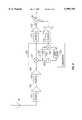
- FIG. 1is a block diagram of an embodiment of the present invention
- FIG. 2is a diagram of a preferred embodiment of a down-converter section
- FIG. 3is diagram of a preferred embodiment of an up-converter section
- FIG. 4is a block diagram of an alternative embodiment of the invention.
- FIG. 1A block diagram of a preferred embodiment of the present invention is shown in FIG. 1 as a down-converter section 15 and an up-converter section 35 connected by a length of cable 25.
- a reference oscillator 40generates a reference signal which is conducted to cable 25 by a diplexer 30.
- Another diplexer 20receives the reference signal from cable 25 and conducts it to a converter 100.
- Converter 100generates a local oscillator (LO) signal from the reference signal and mixes the LO signal with the received signal at a high frequency to produce an intermediate signal at a lower frequency.
- the intermediate signalis conducted by diplexer 20 to cable 25.
- the intermediate signalis received from cable 25 by diplexer 30.
- Diplexer 30conducts the intermediate signal to another converter 200.
- LOlocal oscillator
- Converter 200generates a LO signal from the reference signal received from reference oscillator 40 and mixes the LO signal with the intermediate signal to produce an output signal at a frequency equal to the frequency of the signal received by converter 100.
- the frequency of the reference signal from reference oscillator 40is chosen to be sufficiently low to be transmitted on cable 25 with low loss.
- the LO signal generated by converter 100is such as to produce an intermediate signal at a frequency sufficiently low to be transmitted on cable 25 with low loss.
- FIG. 2A detailed diagram of a preferred embodiment of down-converter section 15 is shown in FIG. 2 in conjunction with an antenna 10 for receiving a GPS signal at 1.57542 GHz.
- the signal from antenna 10will typically be filtered and amplified before being input to converter 100.
- the first filter 101reduces the probability of overloading the preamplifier 102 with out-of-band signals such as cellular radio emissions.
- a suitable device for implementing the functions of filter 101is a Murata DFC21R57.
- the output of filter 101is input to preamplifier 102 which is desirably a low noise amplifier such as a Motorola MMRF1501.
- the output of amplifier 102is then filtered by a filter 103 to further avoid interference.
- the signalthen enters a second low noise amplifier 104 to further increase the gain before frequency conversion and thus reduce noise in the conversion process.
- the total gain before conversionis approximately 30 dB.
- the signalthen enters converter 100 where sum and difference frequencies are generated.
- Means for implementing converter 100are well known in the art.
- converter 100may be implemented using an NEC UPB1004GS.
- the reference signal frequencyis chosen to be 16.368 MHz.
- a LO signal at a frequency of 1.6368 GHzis generated in converter 100 by a voltage controlled oscillator (VCO) 122.
- VCOvoltage controlled oscillator
- VCO 122effectively multiplies the 16.368 MHz reference signal frequency from reference oscillator 40 by a factor of 100 using a standard technique of dividing the LO frequency by 100 and then comparing this frequency with the reference frequency of 16.368 MHz in a phase detector. This is a well known method for generating frequencies that are exact multiples of a reference frequency.
- a functional diagram of converter 100is shown in FIG. 2.
- the reference signalis received from cable 25 by diplexer 20.
- the signalis amplified by an amplifier 114 and is filtered by a filter 113.
- the output of VCO 122is divided by a factor of 100 in a frequency divider 124 and mixed with the reference signal in mixer 123.
- the output of a mixer 123is filtered by a loop filter 125 and input to VCO 122.
- a phase locked loopis implemented to drive the output of VCO 122 to a frequency of 1.6368 GHz.
- the LO signal output by VCO 122is mixed with the received signal in a mixer 121 to produce an intermediate signal at a frequency of 61.38 MHz.
- the intermediate signalis selected by passing the output of mixer 121 through a filter 111 which is tuned to 61.38 MHz.
- This signalis then amplified by an amplifier 112 so that the overall gain is 90 dB in down-converter section 15.
- the intermediate signal from amplifier 112then enters diplexer 20, which is a two-way power splitter.
- the ports of diplexer 20are labelled a, b and c.
- the diplexer employed in a preferred embodimentcomprises Mini-Circuits LRPS 2-1. This device provides 30 dB of isolation between ports b and c, but only 3 dB of attenuation between ports a and b and between ports a and c.
- diplexer 20could be implemented by using passive inductive and capacitive elements. Filter 113 provides additional isolation of the reference signal.
- FIG. 3is a diagram of up-converter section 35.
- the intermediate signal from port a of diplexer 20travels along cable 25 and is received by port a of diplexer 30.
- the operation of diplexer 30is similar to the operation of diplexer 20, and, in fact, may be implemented using identical components.
- the reference signal from reference oscillator 40is amplified by a buffer amplifier 204 and conducted from port c to port a of diplexer 30 to cable 25.
- the intermediate signalis conducted from port a to port b of diplexer 30 to a filter 201. Filter 201 provides additional isolation of the intermediate signal.
- AGCAutomatic Gain Controlled
- AGC amplifier 202comprises an RF Micro Devices RF 2604. After leaving AGC amplifier 202, the signal enters converter 200. The operation and implementation of converter 200 is similar to that of converter 100.
- the local oscillator signal output by the VCO 222is 1.6368 GHz, which is 100 times the frequency of the reference signal received by converter 200 from reference oscillator 40.
- the output of the mixer 221is a signal of frequency equal to 1.57542 GHz.
- the signalis filtered by a filter 211 to select the 1.57542 GHz product of the converter.
- the signalis then attenuated by an attenuator 212 to a level representative of the signal from an active GPS antenna which is what the low cost GPS receiver expects an input signal.
- DC power to down-converter section 15is, as a matter of practical convenience, conducted to down-converter section 15 by cable 25. A separate power source or separate cable could be provided for this purpose.
- reference oscillator 40is located in up-converter section 35, which is typically located in a controlled environment.
- reference oscillator 40could be placed in down-converter section 15. This embodiment is shown in FIG. 4.
- Diplexers 22 and 32are similar in characteristics to diplexers 20 and 30 described above. The essential difference is that the direction of the reference signal through the diplexers and cable is reversed. The implementation of this alternative embodiment would be apparent to one of ordinary skill in the art given the disclosure herein.
Landscapes
- Engineering & Computer Science (AREA)
- Computer Networks & Wireless Communication (AREA)
- Signal Processing (AREA)
- Radar, Positioning & Navigation (AREA)
- Remote Sensing (AREA)
- Physics & Mathematics (AREA)
- General Physics & Mathematics (AREA)
- Position Fixing By Use Of Radio Waves (AREA)
- Circuits Of Receivers In General (AREA)
- Input Circuits Of Receivers And Coupling Of Receivers And Audio Equipment (AREA)
Abstract
Description
The present invention relates to a long cable synchronous signal transmission system.
There are applications for Global Positioning System (GPS) receivers that require the receiver to be placed a thousand feet or more from the antenna. The largest of these applications at the present time is the use of GPS timing receivers for time synchronization and frequency control in telephone networks. This application of GPS timing receivers may require the antenna to be placed atop a large office building and routing a coaxial cable through the building to the telephone network control room where the GPS receiver is located. The losses in standard low cost coaxial cable will be between 10 dB and 30 dB per 100 feet at 1.57542 GHz. It is well known that losses in coaxial cable increase with frequency. For example, RG58C coaxial cable is listed in Buchsbaum's Handbook of Practical Electronics as having 1.6 dB of loss per 100 feet at 10 MHz and 24 dB per 100 feet at 1 GHz. Coaxial cable losses have been dealt with in the past in one of two ways. The first approach involves the placement of a Low Noise Amplifier (LNA) at the antenna with enough gain to overcome the cable losses. However at GPS frequencies, this approach is useful only for cable lengths up to about 200 feet. The second approach utilizes Low Noise Block (LNB) down conversion to a lower frequency at the antenna and transferring the signal at a lower frequency over a coaxial cable to a receiver designed to accept the lower frequency. This approach is not suitable for GPS receivers which are designed to receive the 1.57542 GHz signal. Nor is it a cost-effective solution to redesign the GPS receiver to accept a lower frequency signal. Thus, a need exists for a method and apparatus for transmitting a signal received at a high frequency down a long length of cable with relatively low loss to be received by a receiver designed to accept a high frequency signal.
The present invention seeks to deal with coaxial cable losses in a third way by using a down-converter section at the antenna and an up-converter section at the receiver to convert the signal back to the original frequency received at the antenna. To prevent the introduction of frequency errors, a reference signal is transmitted along the cable and is used in both the up-conversion and down-conversion processes. In summary, a received signal at a frequency too high to be transmitted along a length of cable without appreciable loss in amplitude is down-converted to a lower frequency. The down-conversion process comprises mixing the received signal with a local oscillator signal to produce an intermediate frequency. The intermediate frequency is transmitted down the length of cable. The intermediate frequency is selected to be much lower than the frequency of the received signal. Since signal attenuation along the cable decreases as frequency decreases, the lower frequency intermediate signal will experience lower loss than would the higher frequency received signal. At the opposite end of the cable, the intermediate signal is up-converted to a higher frequency output signal. The up-conversion process is accomplished by mixing the intermediate signal with a local oscillator signal. The local oscillator signals in both the up-converter and down-converter are derived from the same reference signal. For GPS applications, a GPS signal at a frequency of 1.57542 GHz is received by an antenna and enters a converter where it is subtracted from 1.6368 GHz to yield a 61.38 MHz intermediate frequency. The intermediate frequency is amplified and enters a diplexer. The diplexer is an arrangement of a two-way power-splitter and filters that isolate the 61.38 MHz intermediate frequency and the 16.368 MHz reference frequency, thus allowing the coaxial cable to transfer both signals simultaneously. The intermediate frequency arrives at the diplexer on the receiving end of the coaxial cable and is directed to a converter where it is mixed with the 1.6368 GHz local oscillator (LO) signal to reproduce the signal at 1.57542 GHz. The output of the converter is then filtered and attenuated to a signal level that is representative of a signal received by an active GPS antenna with a gain of 30 dB. The GPS receiver connected to the output of the up-converter sees the signal as if it were connected to a standard active GPS antenna. Other frequencies can be used for the local oscillator signals and reference signal to produce any desired intermediate signal frequency, and still achieve the objects of the present invention. The need for this invention stems from the fact that hundreds of thousands of GPS receivers are being manufactured to receive 1.57542 GHz because the overwhelming use for GPS is in positioning and navigation applications, which do not require long coaxial cables. The high volume production of these receivers has driven the price below the cost at which special purpose receivers capable of driving long coaxial cables can be produced. This invention will enable the use of the lower cost GPS receivers in applications requiring cables longer than 100 feet. Timing and frequency control applications are examples of this requirement. However, the principles of the invention may be applied to any received signal to be transmitted over cable for reception by a device designed to receive a signal higher in frequency than what can be efficiently transmitted over a long length of cable.
These and other features, aspects, and advantages of the present invention will become better understood with reference to the following description, appended claims and drawings.
FIG. 1 is a block diagram of an embodiment of the present invention;
FIG. 2 is a diagram of a preferred embodiment of a down-converter section;
FIG. 3 is diagram of a preferred embodiment of an up-converter section; and
FIG. 4 is a block diagram of an alternative embodiment of the invention.
A block diagram of a preferred embodiment of the present invention is shown in FIG. 1 as a down-converter section 15 and an up-converter section 35 connected by a length ofcable 25. Areference oscillator 40 generates a reference signal which is conducted tocable 25 by adiplexer 30. Anotherdiplexer 20 receives the reference signal fromcable 25 and conducts it to aconverter 100.Converter 100 generates a local oscillator (LO) signal from the reference signal and mixes the LO signal with the received signal at a high frequency to produce an intermediate signal at a lower frequency. The intermediate signal is conducted bydiplexer 20 tocable 25. The intermediate signal is received fromcable 25 bydiplexer 30.Diplexer 30 conducts the intermediate signal to anotherconverter 200.Converter 200 generates a LO signal from the reference signal received fromreference oscillator 40 and mixes the LO signal with the intermediate signal to produce an output signal at a frequency equal to the frequency of the signal received byconverter 100. The frequency of the reference signal fromreference oscillator 40 is chosen to be sufficiently low to be transmitted oncable 25 with low loss. Similarly, the LO signal generated byconverter 100 is such as to produce an intermediate signal at a frequency sufficiently low to be transmitted oncable 25 with low loss.
A detailed diagram of a preferred embodiment of down-converter section 15 is shown in FIG. 2 in conjunction with anantenna 10 for receiving a GPS signal at 1.57542 GHz. The signal fromantenna 10 will typically be filtered and amplified before being input to converter 100. Thefirst filter 101, reduces the probability of overloading thepreamplifier 102 with out-of-band signals such as cellular radio emissions. A suitable device for implementing the functions offilter 101 is a Murata DFC21R57. The output offilter 101 is input topreamplifier 102 which is desirably a low noise amplifier such as a Motorola MMRF1501. The output ofamplifier 102 is then filtered by afilter 103 to further avoid interference. The signal then enters a secondlow noise amplifier 104 to further increase the gain before frequency conversion and thus reduce noise in the conversion process. The total gain before conversion is approximately 30 dB. The signal then entersconverter 100 where sum and difference frequencies are generated. Means for implementingconverter 100 are well known in the art. In particular,converter 100 may be implemented using an NEC UPB1004GS. The reference signal frequency is chosen to be 16.368 MHz. A LO signal at a frequency of 1.6368 GHz is generated inconverter 100 by a voltage controlled oscillator (VCO) 122.VCO 122 effectively multiplies the 16.368 MHz reference signal frequency fromreference oscillator 40 by a factor of 100 using a standard technique of dividing the LO frequency by 100 and then comparing this frequency with the reference frequency of 16.368 MHz in a phase detector. This is a well known method for generating frequencies that are exact multiples of a reference frequency. A functional diagram ofconverter 100 is shown in FIG. 2. The reference signal is received fromcable 25 bydiplexer 20. The signal is amplified by anamplifier 114 and is filtered by afilter 113. The output ofVCO 122 is divided by a factor of 100 in afrequency divider 124 and mixed with the reference signal inmixer 123. The output of amixer 123 is filtered by aloop filter 125 and input toVCO 122. Thus, a phase locked loop is implemented to drive the output ofVCO 122 to a frequency of 1.6368 GHz. The LO signal output byVCO 122 is mixed with the received signal in amixer 121 to produce an intermediate signal at a frequency of 61.38 MHz. The intermediate signal is selected by passing the output ofmixer 121 through afilter 111 which is tuned to 61.38 MHz. This signal is then amplified by anamplifier 112 so that the overall gain is 90 dB in down-converter section 15. The intermediate signal fromamplifier 112 then entersdiplexer 20, which is a two-way power splitter. For ease of reference, the ports ofdiplexer 20 are labelled a, b and c. The diplexer employed in a preferred embodiment comprises Mini-Circuits LRPS 2-1. This device provides 30 dB of isolation between ports b and c, but only 3 dB of attenuation between ports a and b and between ports a and c. Alternatively,diplexer 20 could be implemented by using passive inductive and capacitive elements.Filter 113 provides additional isolation of the reference signal.
FIG. 3 is a diagram of up-converter section 35. The intermediate signal from port a ofdiplexer 20 travels alongcable 25 and is received by port a ofdiplexer 30. The operation ofdiplexer 30 is similar to the operation ofdiplexer 20, and, in fact, may be implemented using identical components. The reference signal fromreference oscillator 40 is amplified by abuffer amplifier 204 and conducted from port c to port a ofdiplexer 30 tocable 25. The intermediate signal is conducted from port a to port b ofdiplexer 30 to afilter 201.Filter 201 provides additional isolation of the intermediate signal. The intermediate signal then enters an Automatic Gain Controlled (AGC)amplifier 202 where the losses in the coaxial cable at 61.38 MHz are normalized so that overall gain from the antenna to the output ofAGC amplifier 202 is 80 dB independent of the cable length. The AGC function is necessary to allow any cable length to be used without gain adjustment at installation because 1000 feet of standard coaxial cable such as RG58 will have up to 40 dB of loss at 61.38 MHz where as 100 feet would have only 4 dB of loss. Means for implementation of automatic gain control are well known in the art. Preferably,AGC amplifier 202 comprises an RF Micro Devices RF 2604. After leavingAGC amplifier 202, the signal entersconverter 200. The operation and implementation ofconverter 200 is similar to that ofconverter 100. The local oscillator signal output by theVCO 222 is 1.6368 GHz, which is 100 times the frequency of the reference signal received byconverter 200 fromreference oscillator 40. Thus, the output of themixer 221 is a signal of frequency equal to 1.57542 GHz. After leaving the converter, the signal is filtered by afilter 211 to select the 1.57542 GHz product of the converter. The signal is then attenuated by anattenuator 212 to a level representative of the signal from an active GPS antenna which is what the low cost GPS receiver expects an input signal. Note that DC power to down-converter section 15 is, as a matter of practical convenience, conducted to down-converter section 15 bycable 25. A separate power source or separate cable could be provided for this purpose. In a preferred embodiment,reference oscillator 40 is located in up-converter section 35, which is typically located in a controlled environment. In an alternative embodiment,reference oscillator 40 could be placed in down-converter section 15. This embodiment is shown in FIG. 4. Diplexers 22 and 32 are similar in characteristics to diplexers 20 and 30 described above. The essential difference is that the direction of the reference signal through the diplexers and cable is reversed. The implementation of this alternative embodiment would be apparent to one of ordinary skill in the art given the disclosure herein.
Further, a person of ordinary skill in the art would readily recognize that other values for the local oscillator frequencies and reference frequency described herein could be selected to achieve the objectives of the present invention.
Clearly, changes can be made in the above-described details without departing from the underlying principles of the present invention. A description of a particular embodiment does not determine the scope of an invention. Rather, the scope of the present invention is determined by the following claims.
Claims (7)
1. A long-cable synchronous signal transmission system, comprising:
a reference oscillator for generating a reference signal;
a first converter for mixing a received signal with a first local oscillator signal generated from said reference signal to produce an intermediate signal;
a cable with a first end and a second end;
a first diplexer for conducting said intermediate signal to said first end of said cable and for receiving said reference signal from said first end of said cable;
a second diplexer for conducting said reference signal to said second end of said cable and for receiving said intermediate signal from said second end of said cable; and
a second converter for mixing said intermediate signal with a second local oscillator signal generated from said reference signal to produce an output signal wherein the reference signal and intermediate signal derived therefrom are of frequencies chosen to be operably detectable after transmission through the cable without amplification between the ends of said cable.
2. The system of claim 1, further comprising an automatic gain controller to provide an intermediate signal level that is independent of the length of the cable.
3. The system of claim 1, further comprising an attenuator for attenuating the output signal.
4. A long-cable synchronous signal transmission system, comprising:
a reference oscillator for generating a reference signal;
a first converter for mixing a received signal with first local oscillator signal generated from said reference signal to produce an intermediate signal;
a cable with a first end and a second end;
a first diplexer for conducting said intermediate signal to said first end of said cable and for conducting said reference signal to said first end of said cable;
a second diplexer for receiving said reference signal from said second end of said cable and for receiving said intermediate signal from said second end of said cable; and
a second converter for mixing said intermediate signal with a second local oscillator signal generated from said reference signal to produce an output signal wherein the reference signal and intermediate signal derived therefrom are of frequencies chosen to be operably detectable after transmission through the cable without amplification between the ends of said cable.
5. A method for transmitting a received signal along a long length of cable comprising the steps of:
generating a reference signal;
transmitting said reference signal along the cable;
generating a first local oscillator signal from said reference signal;
mixing said first local oscillator signal with the received signal to produce an intermediate signal;
transmitting said intermediate signal along the cable;
generating a second local oscillator signal from said reference signal;
mixing said second local oscillator signal with said intermediate signal to produce an output signal wherein the reference signal and intermediate signal derived therefrom are of frequencies chosen to be operably detectable after transmission through the cable without amplification between the ends of said cable.
6. The method of claim 5, further comprising the step of automatically controlling the gain of the intermediate signal to provide an intermediate signal level that is independent of the length of the cable.
7. The method of claim 5, further comprising the step of attenuating the output signal.
Priority Applications (1)
| Application Number | Priority Date | Filing Date | Title |
|---|---|---|---|
| US08/926,900US5999795A (en) | 1997-09-10 | 1997-09-10 | RF GPS long cable driver |
Applications Claiming Priority (1)
| Application Number | Priority Date | Filing Date | Title |
|---|---|---|---|
| US08/926,900US5999795A (en) | 1997-09-10 | 1997-09-10 | RF GPS long cable driver |
Publications (1)
| Publication Number | Publication Date |
|---|---|
| US5999795Atrue US5999795A (en) | 1999-12-07 |
Family
ID=25453859
Family Applications (1)
| Application Number | Title | Priority Date | Filing Date |
|---|---|---|---|
| US08/926,900Expired - Fee RelatedUS5999795A (en) | 1997-09-10 | 1997-09-10 | RF GPS long cable driver |
Country Status (1)
| Country | Link |
|---|---|
| US (1) | US5999795A (en) |
Cited By (9)
| Publication number | Priority date | Publication date | Assignee | Title |
|---|---|---|---|---|
| US20060055594A1 (en)* | 2000-08-10 | 2006-03-16 | Mcconnell Richard J | Method and apparatus for reducing GPS receiver jamming during transmission in a wireless receiver |
| US7205939B2 (en) | 2004-07-30 | 2007-04-17 | Novariant, Inc. | Land-based transmitter position determination |
| US7271766B2 (en) | 2004-07-30 | 2007-09-18 | Novariant, Inc. | Satellite and local system position determination |
| US7315278B1 (en) | 2004-07-30 | 2008-01-01 | Novariant, Inc. | Multiple frequency antenna structures and methods for receiving navigation or ranging signals |
| US7339525B2 (en) | 2004-07-30 | 2008-03-04 | Novariant, Inc. | Land-based local ranging signal methods and systems |
| US7339526B2 (en) | 2004-07-30 | 2008-03-04 | Novariant, Inc. | Synchronizing ranging signals in an asynchronous ranging or position system |
| US7339524B2 (en) | 2004-07-30 | 2008-03-04 | Novariant, Inc. | Analog decorrelation of ranging signals |
| US7342538B2 (en) | 2004-07-30 | 2008-03-11 | Novariant, Inc. | Asynchronous local position determination system and method |
| US7532160B1 (en)* | 2004-07-30 | 2009-05-12 | Novariant, Inc. | Distributed radio frequency ranging signal receiver for navigation or position determination |
Citations (8)
| Publication number | Priority date | Publication date | Assignee | Title |
|---|---|---|---|---|
| US5276918A (en)* | 1990-11-16 | 1994-01-04 | Orbitel Mobile Communications Limited | Mobile radio telephone with booster unit |
| US5535441A (en)* | 1994-09-30 | 1996-07-09 | Hughes Electronics Corp. | Method and device for canceling frequency offsets |
| US5600364A (en)* | 1992-12-09 | 1997-02-04 | Discovery Communications, Inc. | Network controller for cable television delivery systems |
| US5682195A (en)* | 1992-12-09 | 1997-10-28 | Discovery Communications, Inc. | Digital cable headend for cable television delivery system |
| US5748049A (en)* | 1994-11-23 | 1998-05-05 | Anadigics, Inc. | Multi-frequency local oscillators |
| US5784683A (en)* | 1995-05-16 | 1998-07-21 | Bell Atlantic Network Services, Inc. | Shared use video processing systems for distributing program signals from multiplexed digitized information signals |
| US5805975A (en)* | 1995-02-22 | 1998-09-08 | Green, Sr.; James A. | Satellite broadcast receiving and distribution system |
| US5898455A (en)* | 1997-12-23 | 1999-04-27 | California Amplifier, Inc. | Interface modules and methods for coupling combined communication signals to communication receivers |
- 1997
- 1997-09-10USUS08/926,900patent/US5999795A/ennot_activeExpired - Fee Related
Patent Citations (8)
| Publication number | Priority date | Publication date | Assignee | Title |
|---|---|---|---|---|
| US5276918A (en)* | 1990-11-16 | 1994-01-04 | Orbitel Mobile Communications Limited | Mobile radio telephone with booster unit |
| US5600364A (en)* | 1992-12-09 | 1997-02-04 | Discovery Communications, Inc. | Network controller for cable television delivery systems |
| US5682195A (en)* | 1992-12-09 | 1997-10-28 | Discovery Communications, Inc. | Digital cable headend for cable television delivery system |
| US5535441A (en)* | 1994-09-30 | 1996-07-09 | Hughes Electronics Corp. | Method and device for canceling frequency offsets |
| US5748049A (en)* | 1994-11-23 | 1998-05-05 | Anadigics, Inc. | Multi-frequency local oscillators |
| US5805975A (en)* | 1995-02-22 | 1998-09-08 | Green, Sr.; James A. | Satellite broadcast receiving and distribution system |
| US5784683A (en)* | 1995-05-16 | 1998-07-21 | Bell Atlantic Network Services, Inc. | Shared use video processing systems for distributing program signals from multiplexed digitized information signals |
| US5898455A (en)* | 1997-12-23 | 1999-04-27 | California Amplifier, Inc. | Interface modules and methods for coupling combined communication signals to communication receivers |
Cited By (11)
| Publication number | Priority date | Publication date | Assignee | Title |
|---|---|---|---|---|
| US20060055594A1 (en)* | 2000-08-10 | 2006-03-16 | Mcconnell Richard J | Method and apparatus for reducing GPS receiver jamming during transmission in a wireless receiver |
| US7205939B2 (en) | 2004-07-30 | 2007-04-17 | Novariant, Inc. | Land-based transmitter position determination |
| US7271766B2 (en) | 2004-07-30 | 2007-09-18 | Novariant, Inc. | Satellite and local system position determination |
| US7315278B1 (en) | 2004-07-30 | 2008-01-01 | Novariant, Inc. | Multiple frequency antenna structures and methods for receiving navigation or ranging signals |
| US7339525B2 (en) | 2004-07-30 | 2008-03-04 | Novariant, Inc. | Land-based local ranging signal methods and systems |
| US7339526B2 (en) | 2004-07-30 | 2008-03-04 | Novariant, Inc. | Synchronizing ranging signals in an asynchronous ranging or position system |
| US7339524B2 (en) | 2004-07-30 | 2008-03-04 | Novariant, Inc. | Analog decorrelation of ranging signals |
| US7342538B2 (en) | 2004-07-30 | 2008-03-11 | Novariant, Inc. | Asynchronous local position determination system and method |
| US7345627B2 (en) | 2004-07-30 | 2008-03-18 | Novariant, Inc. | Land-based local ranging signal methods and systems |
| US7382318B2 (en) | 2004-07-30 | 2008-06-03 | Novariant Inc. | Land-based local ranging signal methods and systems |
| US7532160B1 (en)* | 2004-07-30 | 2009-05-12 | Novariant, Inc. | Distributed radio frequency ranging signal receiver for navigation or position determination |
Similar Documents
| Publication | Publication Date | Title |
|---|---|---|
| US5530929A (en) | Homodyne receiver minimizing oscillator leakage | |
| US5444865A (en) | Generating transmit injection from receiver first and second injections | |
| EP0978167B1 (en) | Dual band radio receiver | |
| US6510317B1 (en) | Satellite digital audio radio service tuner architecture for reception of satellite and terrestrial signals | |
| US6704549B1 (en) | Multi-mode, multi-band communication system | |
| EP1224821B1 (en) | In-building radio-frequency coverage | |
| US7123648B2 (en) | Radio relay apparatus | |
| US7649493B2 (en) | System for transmitting a signal for positioning and method for producing the system | |
| US20030069036A1 (en) | GPS receiver system and method | |
| JPH08111658A (en) | Low-speed data dedicated satellite communication terminal Earth station up-converter High-power amplifier | |
| KR20010051356A (en) | A method and apparatus for transmitting radio frequency signals to and from a pager | |
| US6513163B1 (en) | Embedded forward reference and control | |
| US20010031623A1 (en) | Channel booster amplifier | |
| US5999795A (en) | RF GPS long cable driver | |
| AU748309B2 (en) | Radio transmitter/receiver | |
| JP4663087B2 (en) | Gap filler for digital terrestrial broadcasting | |
| KR100260252B1 (en) | A rf transmittrer and receiver in lmcs | |
| KR100438556B1 (en) | Apparatus and method for processing radio frequency signal in tri-mode mobile terminal | |
| CN219372427U (en) | Transceiver and communication device | |
| US20250007540A1 (en) | Very small aperture terminal for satellite communication with direct conversion and electronic polarization orientation control | |
| JP4074807B2 (en) | Millimeter-wave transmission / reception system, transmission device, and reception device | |
| JP2002271224A (en) | Converter for satellite broadcasting reception | |
| JP2003152586A (en) | Radio communications equipment, radio equipment, and radio communication system | |
| KR100497940B1 (en) | Wireless LAN transmitter | |
| GB2282298A (en) | A cell enhancer for simulcast radio transmission |
Legal Events
| Date | Code | Title | Description |
|---|---|---|---|
| AS | Assignment | Owner name:STARLINK, INC., TEXAS Free format text:ASSIGNMENT OF ASSIGNORS INTEREST;ASSIGNORS:FOWLER, CLARENCE W.;VACCARO, LOUIS J., JR.;HINDMAN, DAVID L.;AND OTHERS;REEL/FRAME:008707/0280 Effective date:19970908 | |
| AS | Assignment | Owner name:STARLINK SPECIAL ASSETS, INC., TEXAS Free format text:ASSIGNMENT OF ASSIGNORS INTEREST;ASSIGNOR:STARLINK, INC.;REEL/FRAME:012621/0696 Effective date:20011203 | |
| AS | Assignment | Owner name:RAVEN INDUSTRIES, INC., SOUTH DAKOTA Free format text:ASSIGNMENT OF ASSIGNORS INTEREST;ASSIGNOR:STARLINK SPECIAL ASSETS, INC.;REEL/FRAME:012631/0163 Effective date:20011205 | |
| FPAY | Fee payment | Year of fee payment:4 | |
| REMI | Maintenance fee reminder mailed | ||
| LAPS | Lapse for failure to pay maintenance fees | ||
| STCH | Information on status: patent discontinuation | Free format text:PATENT EXPIRED DUE TO NONPAYMENT OF MAINTENANCE FEES UNDER 37 CFR 1.362 | |
| FP | Lapsed due to failure to pay maintenance fee | Effective date:20071207 |