US5999518A - Distributed telecommunications switching system and method - Google Patents
Distributed telecommunications switching system and methodDownload PDFInfo
- Publication number
- US5999518A US5999518AUS08/985,386US98538697AUS5999518AUS 5999518 AUS5999518 AUS 5999518AUS 98538697 AUS98538697 AUS 98538697AUS 5999518 AUS5999518 AUS 5999518A
- Authority
- US
- United States
- Prior art keywords
- cell
- channel bank
- queue
- data packet
- switching
- Prior art date
- Legal status (The legal status is an assumption and is not a legal conclusion. Google has not performed a legal analysis and makes no representation as to the accuracy of the status listed.)
- Expired - Lifetime
Links
Images


Classifications
- H—ELECTRICITY
- H04—ELECTRIC COMMUNICATION TECHNIQUE
- H04L—TRANSMISSION OF DIGITAL INFORMATION, e.g. TELEGRAPHIC COMMUNICATION
- H04L49/00—Packet switching elements
- H04L49/50—Overload detection or protection within a single switching element
- H04L49/505—Corrective measures
- H—ELECTRICITY
- H04—ELECTRIC COMMUNICATION TECHNIQUE
- H04L—TRANSMISSION OF DIGITAL INFORMATION, e.g. TELEGRAPHIC COMMUNICATION
- H04L49/00—Packet switching elements
- H04L49/10—Packet switching elements characterised by the switching fabric construction
- H04L49/103—Packet switching elements characterised by the switching fabric construction using a shared central buffer; using a shared memory
- H—ELECTRICITY
- H04—ELECTRIC COMMUNICATION TECHNIQUE
- H04L—TRANSMISSION OF DIGITAL INFORMATION, e.g. TELEGRAPHIC COMMUNICATION
- H04L49/00—Packet switching elements
- H04L49/10—Packet switching elements characterised by the switching fabric construction
- H04L49/104—Asynchronous transfer mode [ATM] switching fabrics
- H04L49/105—ATM switching elements
- H04L49/108—ATM switching elements using shared central buffer
- H—ELECTRICITY
- H04—ELECTRIC COMMUNICATION TECHNIQUE
- H04L—TRANSMISSION OF DIGITAL INFORMATION, e.g. TELEGRAPHIC COMMUNICATION
- H04L49/00—Packet switching elements
- H04L49/15—Interconnection of switching modules
- H04L49/1553—Interconnection of ATM switching modules, e.g. ATM switching fabrics
- H—ELECTRICITY
- H04—ELECTRIC COMMUNICATION TECHNIQUE
- H04L—TRANSMISSION OF DIGITAL INFORMATION, e.g. TELEGRAPHIC COMMUNICATION
- H04L49/00—Packet switching elements
- H04L49/20—Support for services
- H04L49/205—Quality of Service based
- H—ELECTRICITY
- H04—ELECTRIC COMMUNICATION TECHNIQUE
- H04L—TRANSMISSION OF DIGITAL INFORMATION, e.g. TELEGRAPHIC COMMUNICATION
- H04L49/00—Packet switching elements
- H04L49/25—Routing or path finding in a switch fabric
- H04L49/256—Routing or path finding in ATM switching fabrics
- H—ELECTRICITY
- H04—ELECTRIC COMMUNICATION TECHNIQUE
- H04L—TRANSMISSION OF DIGITAL INFORMATION, e.g. TELEGRAPHIC COMMUNICATION
- H04L49/00—Packet switching elements
- H04L49/30—Peripheral units, e.g. input or output ports
- H04L49/3009—Header conversion, routing tables or routing tags
- H—ELECTRICITY
- H04—ELECTRIC COMMUNICATION TECHNIQUE
- H04L—TRANSMISSION OF DIGITAL INFORMATION, e.g. TELEGRAPHIC COMMUNICATION
- H04L49/00—Packet switching elements
- H04L49/30—Peripheral units, e.g. input or output ports
- H04L49/3081—ATM peripheral units, e.g. policing, insertion or extraction
- H—ELECTRICITY
- H04—ELECTRIC COMMUNICATION TECHNIQUE
- H04L—TRANSMISSION OF DIGITAL INFORMATION, e.g. TELEGRAPHIC COMMUNICATION
- H04L49/00—Packet switching elements
- H04L49/30—Peripheral units, e.g. input or output ports
- H04L49/3081—ATM peripheral units, e.g. policing, insertion or extraction
- H04L49/309—Header conversion, routing tables or routing tags
- H—ELECTRICITY
- H04—ELECTRIC COMMUNICATION TECHNIQUE
- H04L—TRANSMISSION OF DIGITAL INFORMATION, e.g. TELEGRAPHIC COMMUNICATION
- H04L49/00—Packet switching elements
- H04L49/40—Constructional details, e.g. power supply, mechanical construction or backplane
- H04L49/405—Physical details, e.g. power supply, mechanical construction or backplane of ATM switches
- H—ELECTRICITY
- H04—ELECTRIC COMMUNICATION TECHNIQUE
- H04L—TRANSMISSION OF DIGITAL INFORMATION, e.g. TELEGRAPHIC COMMUNICATION
- H04L49/00—Packet switching elements
- H04L49/50—Overload detection or protection within a single switching element
- H04L49/501—Overload detection
- H04L49/503—Policing
- H—ELECTRICITY
- H04—ELECTRIC COMMUNICATION TECHNIQUE
- H04Q—SELECTING
- H04Q11/00—Selecting arrangements for multiplex systems
- H04Q11/04—Selecting arrangements for multiplex systems for time-division multiplexing
- H04Q11/0428—Integrated services digital network, i.e. systems for transmission of different types of digitised signals, e.g. speech, data, telecentral, television signals
- H04Q11/0478—Provisions for broadband connections
- H—ELECTRICITY
- H04—ELECTRIC COMMUNICATION TECHNIQUE
- H04L—TRANSMISSION OF DIGITAL INFORMATION, e.g. TELEGRAPHIC COMMUNICATION
- H04L12/00—Data switching networks
- H04L12/54—Store-and-forward switching systems
- H04L12/56—Packet switching systems
- H04L12/5601—Transfer mode dependent, e.g. ATM
- H04L2012/5603—Access techniques
- H04L2012/5604—Medium of transmission, e.g. fibre, cable, radio
- H04L2012/5605—Fibre
- H—ELECTRICITY
- H04—ELECTRIC COMMUNICATION TECHNIQUE
- H04L—TRANSMISSION OF DIGITAL INFORMATION, e.g. TELEGRAPHIC COMMUNICATION
- H04L12/00—Data switching networks
- H04L12/54—Store-and-forward switching systems
- H04L12/56—Packet switching systems
- H04L12/5601—Transfer mode dependent, e.g. ATM
- H04L2012/5603—Access techniques
- H04L2012/5604—Medium of transmission, e.g. fibre, cable, radio
- H04L2012/5606—Metallic
- H—ELECTRICITY
- H04—ELECTRIC COMMUNICATION TECHNIQUE
- H04L—TRANSMISSION OF DIGITAL INFORMATION, e.g. TELEGRAPHIC COMMUNICATION
- H04L12/00—Data switching networks
- H04L12/54—Store-and-forward switching systems
- H04L12/56—Packet switching systems
- H04L12/5601—Transfer mode dependent, e.g. ATM
- H04L2012/5603—Access techniques
- H04L2012/5609—Topology
- H04L2012/561—Star, e.g. cross-connect, concentrator, subscriber group equipment, remote electronics
- H—ELECTRICITY
- H04—ELECTRIC COMMUNICATION TECHNIQUE
- H04L—TRANSMISSION OF DIGITAL INFORMATION, e.g. TELEGRAPHIC COMMUNICATION
- H04L12/00—Data switching networks
- H04L12/54—Store-and-forward switching systems
- H04L12/56—Packet switching systems
- H04L12/5601—Transfer mode dependent, e.g. ATM
- H04L2012/5619—Network Node Interface, e.g. tandem connections, transit switching
- H04L2012/562—Routing
- H—ELECTRICITY
- H04—ELECTRIC COMMUNICATION TECHNIQUE
- H04L—TRANSMISSION OF DIGITAL INFORMATION, e.g. TELEGRAPHIC COMMUNICATION
- H04L12/00—Data switching networks
- H04L12/54—Store-and-forward switching systems
- H04L12/56—Packet switching systems
- H04L12/5601—Transfer mode dependent, e.g. ATM
- H04L2012/5625—Operations, administration and maintenance [OAM]
- H—ELECTRICITY
- H04—ELECTRIC COMMUNICATION TECHNIQUE
- H04L—TRANSMISSION OF DIGITAL INFORMATION, e.g. TELEGRAPHIC COMMUNICATION
- H04L12/00—Data switching networks
- H04L12/54—Store-and-forward switching systems
- H04L12/56—Packet switching systems
- H04L12/5601—Transfer mode dependent, e.g. ATM
- H04L2012/5638—Services, e.g. multimedia, GOS, QOS
- H04L2012/5646—Cell characteristics, e.g. loss, delay, jitter, sequence integrity
- H04L2012/5647—Cell loss
- H04L2012/5648—Packet discarding, e.g. EPD, PTD
- H—ELECTRICITY
- H04—ELECTRIC COMMUNICATION TECHNIQUE
- H04L—TRANSMISSION OF DIGITAL INFORMATION, e.g. TELEGRAPHIC COMMUNICATION
- H04L12/00—Data switching networks
- H04L12/54—Store-and-forward switching systems
- H04L12/56—Packet switching systems
- H04L12/5601—Transfer mode dependent, e.g. ATM
- H04L2012/5678—Traffic aspects, e.g. arbitration, load balancing, smoothing, buffer management
- H04L2012/5679—Arbitration or scheduling
- H—ELECTRICITY
- H04—ELECTRIC COMMUNICATION TECHNIQUE
- H04L—TRANSMISSION OF DIGITAL INFORMATION, e.g. TELEGRAPHIC COMMUNICATION
- H04L49/00—Packet switching elements
- H04L49/30—Peripheral units, e.g. input or output ports
- H—ELECTRICITY
- H04—ELECTRIC COMMUNICATION TECHNIQUE
- H04L—TRANSMISSION OF DIGITAL INFORMATION, e.g. TELEGRAPHIC COMMUNICATION
- H04L49/00—Packet switching elements
- H04L49/55—Prevention, detection or correction of errors
- H04L49/555—Error detection
Definitions
- This inventionrelates generally to the field of telecommunications switching and more particularly to a distributed telecommunications switching system and method.
- CPEcustomer premises equipment
- central officeis connected to several switching units, which are each connected to several smaller switching units, and so on along the "branches" of the tree.
- switching unitsAt the lowest level of switching units, each unit is connected to one or more CPE units.
- the central officedetermines which branch of the tree services the CPE unit in question. The data is then passed to the switching system for that branch, which in turn passes the data on to the next lower level in the switching hierarchy, and so on, until the data reaches the CPE unit.
- This routing schemerequires that each switching system at each level in the hierarchy must store address and routing information for all of the CPE units serviced by it. If the customer base is expanded to include additional CPE units, then all switching systems routing traffic to the new CPE units must be reprogrammed to store the new address and routing information. Therefore, it is desirable to avoid establishing, maintaining, and updating address and routing information storage for the entire network at each switching system therein.
- a needhas arisen for a telecommunications switching system that only maintains addressing and routing information for only the customer premises equipment that it services. Further, a need has arisen for a telecommunications network that avoids the tree structure approach of conventional telecommunications network.
- a distributed telecommunications system and methodare provided which substantially eliminate or reduce disadvantages and problems associated with conventional telecommunications systems.
- a distributed telecommunications switching subsystemthat includes a plurality of switching subsystems or channel banks.
- Each channel bankhas a stored list of addresses.
- a channel bankreceives a data packet, it compares the address of the data packet to its stored list of addresses, and transmits the data packet to another channel bank if the address of the data packet does not correspond to any of the addresses in its stored list of addresses.
- each channel bankonly stores a limited number of addresses pertaining to customers directly serviced by the channel bank and is effectively independent of the other channel banks in the system.
- Another technical advantageis that the modularity of the system allows expansion of service with minimal modification to the existing structure.
- a further technical advantageis that the channel banks may be located remotely from one another without significant degradation in service, allowing customers in different areas to be located "close to the switch,” to decrease access times and improve service for the customers.
- the present inventionmay be advantageously used to facilitate access to asynchronous transfer mode ("ATM”) networks and environments.
- ATMasynchronous transfer mode
- the present inventionprovides for a technique and system that can be employed to interface with, and provide access to, an ATM network.
- the present inventionmay be employed to interface with an ATM network, such as central offices of a public switched telephone network or wide area networks that operate through the transmission of optical signals in ATM format, and to route information between the ATM network and designated subscriber interfaces.
- the present inventionmay be interposed between a wide area network having an ATM backbone and customer premise equipment.
- Such placementallows for the present invention to provide different functions on behalf of the wide area network (such as a "policing" function, which regulates the traffic flow to wide area networks), as well as on behalf of the customer premise equipment (such as a rate adoption function for local area networks).
- Multiple interconnected unitsare preferably used to implement the present invention.
- the multiple unitsmay be physically located in a common place or in remote locations from one another.
- Each unitis associated with a plurality of subscriber interfaces, and performs distinct functions and procedures to the traffic deriving from the ATM network or subscriber interfaces.
- the cumulative effect of the multiple unitsis to form a technique and system that, among other things, routes and controls the ATM traffic amongst the various subscriber interfaces.
- the present inventioncan be considered as a series of distributed ATM switches or nodes that collectively function as a single switching or multiplexing entity.
- the unitsare serially connected to one another (i.e., daisy-chained) such that any one unit is connected to one or two other units.
- the first and last unitsare connected to only one other unit, while the intermediate units between the first and last units are connected to two other units.
- FIG. 1illustrates a block diagram of a telecommunications network
- FIG. 2illustrates a block diagram of a portion of a switching subsystem within the telecommunications network
- FIG. 3illustrates a block diagram of a channel bank unit within the switching subsystem
- FIG. 4illustrates another block diagram of the channel bank
- FIG. 5illustrates a block diagram of a top level memory fabric of the switching subsystem
- FIG. 6illustrates a block diagram of the fabric controls of the switching subsystem
- FIG. 7illustrates a block diagram of the memory management within the switching subsystem
- FIG. 8illustrates a block diagram of a logical queue structure within the switching subsystem
- FIG. 9is a block diagram of a distributed telecommunications switching subsystem
- FIG. 10is a block diagram of a controller for use in the distributed switching subsystem
- FIG. 11is an expanded block diagram of an ingress queue system for use in the distributed switching subsystem
- FIG. 12is a block diagram of a terminating controller for use in the distributed switching subsystem
- FIG. 13is a block diagram illustrating a first upstream flow control system for the distributed switching subsystem.
- FIG. 14is a block diagram illustrating a second upstream flow control system for the distributed switching subsystem.
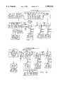
- FIG. 1is a block diagram of a telecommunications network 10.
- Telecommunications network 10includes a central office 11, an asynchronous transfer mode (ATM) switch 12, a time division multiplex (TDM) switch 13, a central digital loop carrier system 14, a remote digital loop carrier system 15, one or more remote terminal 16, and a switching subsystem 100.
- central office 11may receive time division multiplex traffic from TDM switch 13 at any of a plurality of channel banks 17.
- the TDM trafficis received by a line card 18, appropriately processed, and transferred to a common control shelf 19 where the TDM traffic can be passed to an appropriate central digital loop carrier system 14.
- Digital loop carrier system 14may also receive ATM traffic from ATM switch 12.
- Digital loop carrier system 14integrates the TDM traffic with the ATM traffic for transfer, preferably over an optical fiber link 20 to a remote digital loop carrier system 15.
- the remote digital loop carrier system 15may partition the integrated TDM and ATM traffic received over optical fiber link 20 into separate TDM and ATM traffic streams.
- the partitioned TDM traffic streammay be provided to a remote terminal 16 according to its appropriate destination.
- Digital loop carrier system 15may also provide the partitioned ATM stream to switching system 100 that appropriately sends the ATM stream to its appropriate user destination. While FIG. 1 shows switching subsystem 100 as only receiving an ATM stream, switching subsystem 100 may also receive and process TDM streams from telecommunications network 10.
- FIG. 1illustrates a switching subsystem 100, also known as an ATM service access multiplexer, in accordance with a preferred embodiment of the present invention.
- switching subsystem 100may communicate to an ATM switch 12, as commonly found in a central office 14, through a shared communication link 110.
- Switching subsystem 100includes a first switching unit 104a, a last switching unit 104n, and one or more intermediate switching units 104i interposed between the first switching unit 104a and the last switching unit 104n.
- Such switching units 104are connected to one another through bidirectional connections 108, which collectively can be considered to provide for a control loop 112.
- Such connections 108preferably transmit optical signals, such as OC-3 optical signals.
- the switching units 104are each associated to certain subscriber interfaces, specifically, the first switching unit 104a is associated with certain subscriber interfaces by link 106a, the intermediate switching units 104i are associated with other subscriber interfaces by link 106i, and the last switching unit 104n is associated with still other subscriber interfaces by link 106n.
- Bi-directional connections 108 between the unitsallow for the transmission of control and routing information to be transferred between the units.
- the transmission of informationmay be in the downstream direction, such as from the first switching unit 104a to the intermediate switching unit 104i that it is directly connected to.
- informationmay be transmitted in the upstream direction, such as from the last switching unit 104a to the intermediate switching unit 104i that it is directly connected to.
- Various levels of controlmay be provided by the switching subsystem 100, such as the following:
- instantaneous controlsincluding controlling the routing of ATM cells, the discarding of selective ATM cells, the signaling of ATM cell mapping, statistics gathering concerning ATM cells, and the marking of ATM cells;
- ATM cellsinclude information such as virtual path (“VP") and virtual circuit (“VC”) routing information, and information concerning their termination (“terminating information”).
- Each switching unit 104analyzes and evaluates the information included with each ATM cell. If the ATM cell identifies VP or VC routing information that is associated with a particular switching unit 104 analyzing the cell, then the cell is forwarded by that particular switching unit to the appropriate destination. Similarly, if the ATM 104 cell includes terminating information that is associated with the particular switching unit 104 evaluating the cell, then the cell is terminated by that particular switching unit 104. In the absence of matching routing or terminating information between the ATM cell and the evaluating switching unit 104, then the evaluating unit passes the cell downstream to the next switching unit 104. That switching unit 104 will then undertake similar analyses and evaluations.
- VPvirtual path
- VCvirtual circuit
- certain switching units 104are operable to forward or terminate certain ATM cells. However, when the multiple switching units 104 are considered collectively, they are able to either forward or terminate all of the ATM cells. As such, the switching subsystem 100 provides for a distributed switching technique.
- a conformant stream of informationis preferably transmitted between the switching units 104. Such conformant stream is established by the imposition of control procedures through the use of the control loop 112.
- a fairness analysis and credit-based schememay, for example, be established through the control loop 112 to control upstream congestion between the switching units 104.
- the first switching unit 104apreferably generates a command cell in the downstream direction.
- the command cellincludes information that defines the credits to be awarded to each unit switching 104, in accordance with the fairness analysis and assessment, and effects the downstream serial transmission of that cell to the other units.
- the last switching unit 104nIn response to reception of the command cell, the last switching unit 104n generates a feedback status cell, which includes feedback status information, such as the congestion status and behavioral attributes of a given shelf.
- the feedback status cellis, however, passed upstream and the feedback information therein is modified by the intermediate switching units 104i.
- each intermediate switching unit 104ipreferably supplements the information already included in the feedback status cell, which concerns other units, with feedback information concerning that particular unit.
- Using the information provided for in the command cell, together with the feedback status cellallows for a credit-based scheme to take place whereby each switching unit 104 is informed of the number of credits it is awarded.
- the number of creditsrelates to the number of ATM cells that a switching unit 104 can pass upstream in a given period of time.
- a particular switching unit 104may start to launch ATM cells into the upstream connection 108 until its credits are exhausted.
- the above-described fairness analysis and credit-based schemeis preferably implemented by designating one of the switching units 104 as a master, and the other units as slaves.
- the master switching unit 104preferably the first switching unit 104a, should be operable to compute the credits awarded to each slave unit switching 104 based on the command and feedback status cells, and to inform each slave switching unit of its allotted number of credits.
- the connections 108 between the switching units 104are regulated such that upstream congestion (i.e., a bottleneck) is avoided.
- FIG. 2is a block diagram of switching unit 104.
- Switching unit 104includes an asynchronous transfer mode bank channel unit (ABCU) card 22 and a plurality of asynchronous digital subscriber line (ADSL) line cards 24. While ADSL line cards 24 are to be described preferably with respect to the asynchronous digital subscriber loop protocol, ADSL line cards 24 may be implemented with other appropriate transmission protocols.
- switching unit 104receives asynchronous transfer mode cells at an ATM cell multiplexer add/drop unit 25. Add/drop unit 25 determines whether each ATM cell received has the appropriate destination and addressing information for a user serviced by ADSL line cards 24 associated with ABCU card 22. If not, then the ATM cell is passed to the next switching unit 104 within switching subsystem 100.
- add/drop unit 25identifies an ATM cell with the correct addressing and destination information
- the ATM cellis forwarded to an appropriate bus interface 26 for transfer to an appropriate ADSL line card 24.
- the appropriate ADSL line cardincludes a bus interface 27 to extract the ATM cell and provide it to a transceiver 28 where the ATM cell is placed into the appropriate ADSL transmission format for transmission to a remote unit 29.
- Remote unit 29processes the ADSL transmission received from ADSL line card 24 through a transceiver 30, physical layer unit 31, segmentation and resegmentation unit 32 or other appropriate device and a user interface 33 for transmission to an end user.
- ABCU card 22may receive TDM traffic over a timeslot interchange cable 34 from TDM switch 13 through a switching device such as digital loop carrier system 15.
- ABCU card 22includes a timeslot assigner 35 that places the TDM traffic into a subscriber bus interface (SBI) protocol format.
- SBIsubscriber bus interface
- the TDM traffic in the SBI protocol formatis provided to an SBI selector 36 and sent to the appropriate ADSL line card 24 for transmission to the end user.
- ADSL line card 24receives an ADSL transmission from remote unit 29 and places the ADSL transmission into an appropriate ATM or TDM traffic stream at bus interface 27.
- the ATM and TDM traffic streamsare transferred to a corresponding SBI selector 36 in order to provide the TDM traffic to timeslot assignment 35 and the ATM traffic to add/drop unit 25.
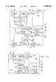
- FIG. 3is a simplified block diagram of ABCU card 22.
- ABCU card 22receives asynchronous transfer mode cells from ATM switch 12 at a physical layer interface 40.
- a downstream virtual path (VP) lookup table 42 and a downstream virtual circuit (VC) lookup table 44are used in determining whether the ATM cell is destined for this ABCU card 22.
- a comparisonis done at downstream VP lookup table 42 to determine whether there is a match in the VP addressing. If a match occurs, the ATM cell is placed into an appropriate queue 46 and is scheduled for transmission to associated ADSL line card 24. If a match did not occur at downstream VP lookup table 42, a comparison is done at downstream VC lookup table 44.
- downstream VC lookup table 44If a match occurs at downstream VC lookup table 44, then the ATM cell is sent to queue 46. If a match still has not occurred, a downstream CPU lookup table 48 is consulted to determine if the ATM cell is a control cell to be processed by the CPU on the ABCU card 22. If a match occurs at the downstream CPU lookup table 48, the ATM cell is passed to the CPU of ABCU card 22. If there is still no match, then the ATM cell is not destined for this ABCU card 22. The ATM cell is then passed to the next switching unit 104 within switching subsystem 100. The next switching unit 104 performs a similar lookup process described above. ATM cells provided to ADSL line card 24 are placed into a buffer 50, processed by a transmission convergence layer 52, and sent to the remote unit 29 through a physical layer interface 54.
- ADSL line card 24receives an ADSL transmission from remote unit 29 and physical layer interface 54.
- the ADSL transmissionis processed by TC layer 52 and the resulting traffic is placed into a buffer 56.
- the resulting trafficis sent from buffer 56 to a holding queue 58 on ABCU card 22.
- Comparisonsare done on the traffic cell at upstream VP lookup table 60 and upstream VC lookup table 62. If no match is found, the traffic cell is sent to the CPU of ABCU card 22 for further processing. If an appropriate match occurs, the traffic cell is placed into an upstream queue 64 where it awaits scheduling for transmission by a credit scheduler 66.
- ABCU card 22also receives ATM cells from another switching unit 104.
- ATM cells received from another switching unit 104are processed by an upstream CPU lookup table 68 determined whether the receive cell is a control cell. If so, the ATM cell received from another switching unit 104 is passed to the CPU of ABCU card 22 for further processing. If it is not a control cell, the ATM cell received from another switching unit 104 is placed into a hop queue 70.
- a selector 72determines which of the cells in the hop queue 70 and the cells identified by the credit scheduler 66 from the upstream queue 64 are to be transmitted through a physical layer interface 74 to ATM switch 12.
- FIG. 4provides a more detailed view of ABCU card 22.
- ABCU card 22may have a switch controller 80 that performs the VP and VC lookup of ATM cells received from ATM switch 12. If a VC or VP match occurs a controller 80, the ATM cells passed to queue 46 are sent to an appropriate ADSL line card 24 as determined by a scheduler 82. A rate adapter transfers the ATM cell from queue 46 over the cell bus to ADSL line card 24 at the appropriate rate as determined by an adapter controller 86. If a lookup match does not occur at controller 80, the ATM cells are placed into a CPU queue if determined to be a control cell, or a bypass queue area 88 for transfer to the next switching unit 104. Transfer from the bypass/CPU queue 88 is determined by a scheduler 90. ATM cells within bypass queue 88 are transferred to a TC layer 92 and a physical layer interface 93 to the next switching unit 104.
- Switch controller 80identifies the destination for the ATM cell received from switching unit 104 and places it into the appropriate queue area 94 for external transfer or one of the other queues for internal transfer.
- Switch controller 80also may receive cells from ADSL line cards 24 through buffer unit 58 as loaded by a recovery unit 96. Cells not in an appropriate ATM cell format are placed into a queue 97 and processed into the proper format by a segmentation and resegmentation (SAR) unit 98.
- SARsegmentation and resegmentation
- Other types of processingmay be performed on ATM cells analyzed by switch controller 80 through a per VC accounting unit 81, a cell discard unit 83, and a usage parameter control policing unit 85.
- Switch controller 80may also interface with TDM traffic received from TSI cable 34 through a custom TC layer 87 and a physical layer interface 89. Switch controller 80 may also provide cells for conversion to TDM format to a buffer queue 75. Cells in buffer queue 75 are transferred to a TDM cell layer 77 as determined by a scheduler 79 and then sent over TSI cable 34 through a physical layer interface 73. Switch controller 80 is capable of processing ATM cells and TDM traffic for internal and/or external routing and rerouting of traffic from any place of origination to any place of destination.
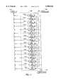
- Switching subsystem 100provides daisy chaining of multiple units or shelves.
- the present inventionis described as having nine switching units concurrently, however, any number of intermediate shelves 104i may be implemented.
- all the switching unitscooperate to implement a distributed switch process and distributed real time control processes including fairness.
- the daisy chaining queue (bypass) methodtakes priority over all local queues.
- each switching unitgenerates a conformant cell stream where the sum of all the rates from the multiple switching units equal the OC-3 rate.
- the resultant behavior of the nine switching unitsis equivalent to a single ATM switching node.
- Switching subsystem 100implements advanced functions that are generally transparent to the data path traffic.
- a control loop 112 between the switching units 104permits the switching units 104 to cooperate on the various system functions.
- the switching units 104are classified as first, intermediate or last.
- the first, intermediate, and last switching units 104generally run similar software, but each of the switching units 104 may have its own unique processes.
- Switching subsystem 100is capable of both VP and VC cell routing with support for up to eight or more traffic classes.
- the control levels provided by the switching subsystem 100can be grouped into five categories, although other control levels are possible. The five exemplary categories are:
- Switching units 104cooperate to implement a distributed ATM switch. These switching units 104 can be either co-located or remotely dispersed.
- These switching units 104cooperate to implement a single ATM switch node. Different procedures are required in the three types of shelves (first, intermediate, last) to implement the distributed switch functions.
- an asynchronous transfer mode bank channel unit (ABCU) card 22 resident within each switching unitprovides the functionality for the distributed MegaSLAM switch.
- the nine switching units 104are daisy chained via their corresponding ABCU cards and may reside in different locations.
- the logic resident on the ABCU card 22implements the cell routing function for any ingress cells from either the network OC-3c, the daisy chain OC-3c or the Upstream time division multiplexed (TDM) bus stream.
- the virtual circuit validation processis a two stage process.
- the first stage logic on the ABCU card 22checks to see if a virtual path (VP) connection is provisioned for this ingress cell.
- Each ingress interfacecan be provisioned to support either user to network interface (UNI) or network to network (NNI) interfaces.
- the virtual path lookupis preferably a linear table where the 8/12 VP bits point to a VP -- descriptor. Thus, a table with 256 byte or 4 Kbytes VP -- descriptor entries may be used.
- the VP -- descriptorcontains the required connection information. If the virtual path lookup is successful, then the cell level processing is implemented by the ABCU card 22 and the cell is forwarded to the appropriate subscriber interface destination.
- Use of the linear lookupprovides for a fast return of a VP -- lookup -- failure indication in the event of a virtual path look up failure. Preferably this indication will be provided to the next stage within two clock cycles.
- a virtual circuit (VC) lookup sequenceis triggered by the VP -- lookup -- failure indication from the previous state.
- the virtual circuit lookupis preferably implemented in hardware by a sorted list that supports a maximum of 2K virtual paths. The process starts near the middle of the list and tests to see if the current 24/28 bit virtual circuit bit pattern is equal to, greater than or less than the pattern from the VP -- descriptor entry. This hardware test preferably requires 2 clock cycles, or less, to complete. At 50 MHZ, this would permit 25 iterations each requiring 40 ns before the 1.0 ⁇ s deadline.
- This designmay be used in OC-3, OC-12, or other applications. This design further may support applications having 64,000 virtual circuits or more.
- the cellis tested by a third stage that evaluates the cell against 8 registers sets that preferably identify CPU terminated cells. If a match condition is found, the cell is passed to the ABCU card 22 resident CPU.
- These registerscan be programmed to strip operation, administration, and maintenance (OAM) cell, resource management(RM) cells, and other cells, out of the cell streams.
- the cellmay be passed via a separate FIFO to the next switching unit 104 in the daisy chain.
- each switching unit 104is programmed to terminate a subset of the virtual circuits for the downstream path. But as a whole all the switching units 104 terminate all the downstream virtual circuits.
- the last switching unit 104nimplements the mis-inserted cell processing function as a proxy for all the daisy chained switching units 104. Thus, the last switching unit 104n acts as a proxy for all exception events for the distributed switch fabric.
- the nine distributed switching units 104cooperate to produce a conformant stream that not only fits into the communication link bandwidth, but at the same time provides fairness to the class of service that is oversubscribing the shared communication link to the CO resident ATM switch.
- a control loop initiated by the first switching unit 104apreferably provides the primitives necessary to implement the distributed fairness process.
- the feedback control loopis initiated by the last switching unit 104n and the cell is modified by the intermediate switching units 104.
- a credit based schemeis implemented and the first switching unit 104a tells all other switching units 104 how many cells they can send for the given control period.
- the fairness analysis in the first switching unit 104ais undertaken to compute the credits that each switching unit 104 gets for a given control period.
- the fairness algorithmwill generate conformant streams in each switching unit 104.
- Each switching unit 104 in the daisy chaintreats the upstream daisy chain as the highest priority stream and queues the cell in the Bypass queue.
- the locally conformant streamis derived from the output side of the Ingress -- queue -- [7.. 0].
- the queuesare serviced on a priority basis with a credit based algorithm.
- the logic on the ABCU card 22generates the conformant stream by launching the permitted number of cells during the current control period. Assuming the control period is in fact equal to 128 cell times on the OC-3c, then each switching unit 104 is permitted to launch its portion of the 128 cell budget.
- the credit based schemeguarantees that the physical OC-3 pipe never becomes a bottleneck in any of the daisy chained links.
- the fairness algorithm, and its associated credit based control function, for the multiple switching units 104should be based on a control interval fast enough such that the ingress cell exposure does not consume more than a small fraction of the total buffer resources (say 5% max). It is believed that a stable (non-oscillating) algorithm is possible if the rate of change of the aggregate cell buffers is limited to a small number ⁇ 5%.
- the planned aggregate cell bufferis 8K cells. Thus, five percent exposure would be about 400 cells. If the ingress rate is worst case 1.0 us per cell then the control process should be faster than 400 us.
- the basic mechanism that permits that upstream algorithm to operate in a distributed manner over the daisy chained switching units 104is the credit based scheduler in each switching unit 104.
- the credit based schedulercooperates with the controller in the first switching unit 104a.
- the communication of the controlling primitivesis accomplished with out of band control cells.
- One point to multipoint cellis sent in the down stream direction from the first switching unit 104a of all subordinate switching units 104.
- This downstream cellcontains the primitive that defines the credit granted to each switching unit 104.
- the last switching unit 104ninitiates a feedback status cell that each switching unit 104 modifies which is eventually terminated on the first switching unit 104a.
- the feedback cellcontains one or more primitives that define the congestion status and or queue behavioral attributes of the given switching unit 104.
- the upstream buffer resourcesare organized into a free list of buffers.
- the size of the buffersis a provisioned parameter but during system run time one fixed size may be used is 64 byte aligned. The size may be 64, 128, 256 or 512 bytes.
- the cellsare mapped into the buffers as 52 bytes.
- the free list of buffershas three trigger levels plus one normal level they are;
- level zeroIf no levels are triggered (i.e. level zero), then all ingress cells are enqueued in the eight queues as a function of the VC -- descriptor queue parameter.
- the eight queuescan be serviced with any algorithm with one being a priority algorithm.
- the cellsare then mapped into the OC-3 PHY layer. If level one is triggered, then CLP marking and EFCI marking is implemented on the programmed number of cell streams destined to some of the queues. If level two is also triggered, then level one procedures remain in effect. This is possible because packet level discard will occur before the cells are queued into the respective queue.
- the EPD procedureoperates on ingress cells with port granularity. The total number of EPD circuits implemented are shared among the ingress ports.
- Each ingress cellis associated with a VC -- descriptor and the target queue is defined in the VC -- descriptor.
- the aggregate of all upstream VCI/VPIare evaluated against the active EPD logic elements that are shared with all the ports. These EPD logic elements store the context of the in-progress packet discards. If there is a match, then the EPD or PPD procedure is implemented by the hardware. In other words the cell is not queued in one of the 8 queues.
- a pipelined implementationis envisioned where the VC -- descriptor lookup occurs and a primitive is appended to identify the target queue and source port. The next state in the pipeline evaluates the cell to match it for a discard VCI/VPI in progress for the given port.
- TBD packets destined for one of eight queuescan all be in the discard mode until the end of message (EOM) marker state.
- EOMend of message
- the action of writing the EPD -- cntl[ ] resistersets a go command flag.
- the initialization of the EPD -- cntl[ ] registersis implemented by a write cycle to the register.
- each switching unit 104manages its own congestion state and discard procedures to enforce fairness. Any locally computed status primitives can be encoded and placed into the upstream status cell that is part of the control loop.
- the 10 upstream queuesare serviced by a controller that launches a predetermined number of cells during the current control period.
- the two queues serviced with the priority algorithmare the Bypass queue and the CPU queue.
- Each queueis serviced by a scheduler and one provided scheme may be to read each queue until empty before advancing to the next queue.
- the controllerblindly launches all cells from the Bypass queue and the CPU queue since it is assumed that these streams are already conformant and have been previously scheduled by another shelf.
- the CPU cellsare important for real time controls but are considered negligible from a system load point of view. The cells from these two queues are not counted by the controller.
- the controlleris granted a fixed number of credits for the local ingress queue[7. .0] for the current control period. As the controller services these queues, the credit counter is decrement until it reaches zero. At this point, the controller stops and waits for the next control period before launching any more cells. Due to boundary conditions the controller may not reach zero before the end of the control period. The controller, when reinitialized for the next control period, remembers the remainder from the previous period. The controller, during the current period, may first exhaust the counter from the previous period before decrementing the counter for the current period.
- the boundary conditionsimpact the accuracy of the fairness algorithm. It is expected that the delay of remote daisy chained switching units 104 may cause short term bursts from these switching units 104 that appear to be in excess of the allocated credits.
- the deadline for feed time controlsare about two or three orders of magnitude slower than the per cell deadline. These controls are all implemented by a RISC CPU on the ABCU. The CPU is expected for cooperate with the peer CPUs in other shelves that may exist in a daisy chained configuration.
- the cellsare fanned out to their target switching units 104 via the VC/VP descriptor lookup in each switching unit.
- the cellsare enqueued into either a high priority or a low priority queue that is associated with each drop (or port).
- the ABCU card 22is capable of 22 sets of these dual priority queues.
- Each queueuses a real time buffer attached to the queue from the free list.
- the cellsare conditionally EFCI marked and some low priority traffic classes may be CLP marked.
- mapping cells over the shared downstream cell busis implemented with a provisioned rate adaptation procedures.
- Feedback over the TDM busprovides the mechanism to ensure that the small FIFO on the line channel card 24 does not overflow or underflow.
- Each switching unit 104implements the congestion policies and thus each switching unit 104 may be at a different congestion level. It is felt that if sufficient buffer resources are allocated to the downstream path, then interference generated by the upstream path consuming buffer resources can be minimal.
- All the slave switching units 104participate in generating a feedback status cell that is sent to the first switching unit 104a.
- This cellcontains the congestion state, the free list size and future primitives for the downstream direction.
- the 16 bit control word for each of the slave switching units 104has the following format, i.e., credit
- the first switching unit 104aruns an algorithm that computes the credits as a proxy for all first switching units 104.
- the first switching unit 104aoperates on a fixed control period. A reasonable fixed period may be 128 cell time intervals on an OC-3 link. This period is about 350 ⁇ s.
- the first switching unit 104acomputes the credits for each of the other switching units 104a. The sum of all credits will be 128 this would include the credits for the first switching unit 104a. The sum of all credits is always equal to the controlling cell internal period.
- the congestion stateis L0 or L1 then all switching units 104 are granted credits such that the queue occupancy stays near zero. Since the bursty nature of the ingress traffic is unpredictable at any instance in time, any one switching unit 104 may be getting more credits than another switching unit 104. The goal being that while the system as a whole is in the L0 or L1 state, the algorithm permits large bursts from any switching unit 104.
- the creditsare modulated in a manner such that the switching units 104 get enough credits to empty their queues. For example, it does not make sense to give credits to a switching unit 104 if it is not going to use them. The first switching unit 104a would know this from the free list feedback control word.
- each slave switching unit 104Upon receiving the credits, each slave switching unit 104 starts to launch cells into the upstream OC-3c link until its credits are exhausted. The slave switching unit 104 simply remains inactive until the next downstream control cell grants more credits. During the inactive state, the PHY device will insert idle cells into the OC-3c when necessary.
- the slave switching unit 104 generated feedback control cellis initiated in the last switching unit 104n excluding the fields of the intermediate switching units 104i which are all 1's.
- Hardware in the intermediate switching units 104iORs in its 32 bit feedback word, recalculates the CRC-10 and then sends the control cell to the next switching unit 104.
- This hardware processshall be completed within less than two cell time intervals.
- the softwareis only required to write the 16 bit feedback word at the control interval rate (i.e. for the 128 cell interval this is about 350 us).
- Slave switching unit 104 generated status cellsare mapped into a following standard OAM format
- the 32 bit status word for each of the slave switching units 104has the following format, i.e. shelf -- status[7..0].
- Switching subsystem 100may be either a deterministic ingress traffic multiplexer that may be distributed over a number of switching units 104 or a statistical ingress traffic multiplexer that also supports a distribution of multiplexer functions over a number of switching units 104. Switching subsystem 100 may also include advanced queuing and congestion avoidance policies. In the downstream direction, switching subsystem 100 support oversubscription with queuing and congestion avoidance policies and is permanent virtual circuit (PVC) based. Switching subsystem 100 uses a centralized shared memory ATM switch fabric. Switching subsystem 100 is preferably capable of supporting an aggregate downstream cell rate of 370,000 cells per second and an upstream burst aggregate cell rate of 222,000 cells/sec for each of nine switching units 104. The aggregate ingress rate for switching subsystem 100 is therefore 2,000,000 cells/sec. The downstream rate supports one full OC-3c.
- the upstream ratesupports over-subscription of the OC-3c by a factor of 5.4.
- the burst upstream ratecan be sustained until switching subsystem 100 enters into a congestion imminent state.
- Cell bufferspreferably provide sufficient buffer resources for queuing up to 2 ⁇ 1500 byte packets from the 22 ingress ports per shelf simultaneously.
- the architecturepreferably supports 22 physical ATM ports in each shelf (i.e. two per slot).
- the downstream directionalso supports oversubscription. For the most part this is handled by the ATM network including the CO resident ATM switch which is delivering the OC-3c to switching subsystem 100.
- Switching subsystem 100supports bursts that exceed the egress bottleneck pipe capacity.
- two queuesare provided in the downstream direction. One of these queues is intended for step function stream (i.e. UBR etc.) that may be oversubscribed. The other queue would be used for streams that require a guaranteed QoS (i.e. CBR, VBR etc.).
- the buffersare sized to support up to 1 ⁇ 1500 byte packet per egress port.
- the ingress architecture of switching subsystem 100may be implemented as ingress streams or implemented in preferably 16 queues that can be assigned to up to 16 traffic classes with over-subscription.
- the traffic classesare organized from highest to lowest priority.
- Each traffic classcan be further subdivided into multiple groups, however, each group preferably requires its own queue.
- Mixed mode scheduler operationis supported in order to provide MCR>0 for some of the lower priority queues.
- An example configuration, which utilizes 16 queues,could be four traffic classes where each traffic class has four groups.
- Switching subsystem 100may provide a tiered congestion hierarchy and each class of service may be at a different congestion state. When switching subsystem 100 is oversubscribed, the lowest priority traffic class will enter the congestion imminent state.
- Switching system 100then implements packet discard policies including early packet discard (EPD) or partial packet discard (PPD).
- packet level discard algorithmsoperate on ATM adaptation layer five (AAL5) traffic streams. If the load offered from the remaining higher priority traffic classes remains within the OC-3 limit, then these traffic classes would not enter the EPD state.
- AAL5ATM adaptation layer five
- the access networkwill deliver nearly ideal quality of service (QoS) parameters (cell delay variation (CDV), CTD etc.) for the higher priority classes.
- QoSquality of service
- CDVcell delay variation
- the EPD/PPD processworks in conjunction with the fairness process.
- the group members of the traffic classare proportionally affected by packet level discards.
- multiple groupscan be provisioned each with a different level of performance. This is achieved by setting up one queue for each group.
- the congestion policiesare applied to the groups that belong to a class of service.
- provisioned parameterspermit the performance to vary between the groups.
- the architecturesupports per virtual circuit assignment to a traffic class and to a group within that traffic class.
- Switching system 100provides daisy chaining for a plurality of switching units 104.
- the processesapply nine switching units 104 concurrently, although other numbers of switching units 104 are possible.
- the switching units 104cooperate to implement the fairness process.
- the daisy chaining queue (bypass) processtakes priority over local queues.
- each switching unit 104generates a conformant cell stream where the sum of the rates from the multiple switching units 104 equal the OC-3 rate. This results in nearly identical queuing delays for the switching units 104.
- Switching subsystem 100is flexible and may be characterized to support a downstream rate of 8.192 Mbps and an upstream rate of 2.048 Mbps for each residence or other drop.
- the specific physical interface to the home, in many cases,will have less bandwidth, and thus switching subsystem 100 is flexible to accommodate the low end rates of 128 Kbps downstream and 128 Kbps upstream.
- Data rates specified hereinare merely exemplary, however, and other data rates may be used as well.
- Switching system 100can support classes A, B and C.
- the ATM Forumhas defined traffic types that map into the ITU classes, which are CBR, rtVBR, VBR, ABR and UBR.
- Switching system 100may provide 16 queues that can be assigned to the traffic classes traversing through the access network. Thus, one or more queues could be used by a particular class of service. The queues are organized from highest to lowest priority.
- connection admission controlThe mapping of any of these traffic classes through switching subsystem 100 is achieved by a connection admission control (CAC) process.
- CACconnection admission control
- the CAC processshould provision the channels, with their associated attributes, only when the QoS can be guaranteed to the user.
- the behavior of switching subsystem 100depends on the CAC process.
- Switching subsystem 100provides features and enhancements not required by the GR-2842-CORE.
- the enhancementsinclude statistical multiplexing and virtual path/circuit switching capabilities.
- the ATM switcheswill use the Virtual UNI functions.
- CACConnection Admission Control
- the ATM switchterminates the signaling streams as defined in GR-2842-CORE and acts as a proxy Connection Admission Control (CAC) entity for switching subsystem 100.
- CACConnection Admission Control
- the ATM switchshould provide a Usage Parameter Control (UPC) (policing) function for the virtual UNI drops resident in the switching subsystem 100.
- UPCUsage Parameter Control
- Switching subsystem 100implements advanced functions that are generally transparent to the data path traffic.
- a control channel between switching units 104permits the switching units 104 to cooperate on the various system functions.
- the switching units 104are classified as first, intermediate or last.
- the first, intermediate, and last shelf classesgenerally run similar software, but each of the classes may have its own unique processes.
- the architectureis capable of both VP and VC cell routing with support for up to eight or more traffic classes.
- the control levels provided by the MegaSLAMcan be grouped into five categories although other control levels are possible. The five exemplary categories are:
- the downstream interface between the ATM switch 12 and switching subsystem 100is implemented over an OC-3c pipe.
- This pipecan be over-subscribed by a back end ATM network associated with the ATM switch 12 and its associated Connection Admission Control process (CAC).
- CACConnection Admission Control process
- the CAC process running in the ATM switch 12would be able to grant bandwidth resources on this OC-3c substantially in excess of the OC-3c pipe capacity.
- the processwould preferably rely on statistical methods to define the upper limit of its bandwidth assignment.
- the CAC processmay provision 200 user channels, each with a PCR of 1.5 Mbps, which would result in a worst case bandwidth load of 300 Mbps.
- the actual normal offered load on the OC-3cmay be in the 100 Mbps range or less. In this case, no cell discards would occur in the CO resident ATM switch 12.
- the user sourcesmay attempt to load the backbone ATM network to 200 Mbps or more.
- the TCP/IP protocol with its inherent rate reduction algorithmswould slow down the user sources until a reasonable ratio of successful packets are getting though telecommunications network 10.
- the user sources in this embodimentwould slow down to an aggregate rate that is approximately equal to the bottleneck rate (in this case the OC-3c pipe). Therefore, the downstream direction can be greatly oversubscribed while still delivering acceptable level of performance to each user port.
- the backbone ATM networksupports advanced discard policies (e.g. EPD), then the system throughput would be maximized. This is due to the one for one relationship between the discarded AAL5 packet and the TCP/IP layer packet retransmit.
- Switching subsystem 100sees the oversubscribed load (from the 200 user sources) offered on the downstream OC-3c pipe.
- the ATM switch 12would fill the OC-3c, and any cells in excess of the 150 Mbps rate would be discarded by the ATM switch 12 when its buffers overflow.
- the ATM traffic classescan be grouped into two types of streams.
- the predictable, traffic-shaped streamse.g., CBR, VBR
- unpredictable, fast-rate-of-change streamse.g., UBR, ABR
- the MegaSLAMdelivers the predictable traffic-shaped streams in a deterministic manner, which guarantees delivery of these cells over the bottleneck PHY.
- the CAC processpreferably ensures that the traffic-shaped streams remain within the bandwidth bounds of the bottleneck link.
- the remaining unpredictable, fast-rate-of-change cell streamswhich frequently are step function rate of change streams, are lower priority.
- Sufficient buffer capacityis preferably provided to absorb packet size bursts, but when the buffer resources are exhausted then these streams will invoke the congestion policies such as cell discard. This approach protects the traffic-shaped stream from the unpredictable behavior of the fast-rate-of change streams.
- the peak cell rate (PCR) parameter for step function streamscan be set at any value including values that exceed the bottleneck PHY port rate.
- the 64 "goodput,” or actual throughput for the application, achieved over the PHY portwould be a function of the traffic pattern, buffer resources, and congestion policy.
- a system usermay empirically tune the system parameters relating to buffer size, traffic pattern, and congestion policy.
- the systemis preferably optimized using EPD/PPD, with the system goodput preferably being in the range of 70% to 100%.
- Over-subscriptionis desirable for the downstream circuits due to the largely client server architectures that most applications require.
- high-bandwidth, content-rich Web pagesare downloaded to the client in response to low-bandwidth upstream requests.
- a typical Internet applicationmight have an optimal ratio of downstream to upstream bandwidth of about 10:1.
- statistical multiplexing in the upstream directionwould generally not be required, because the upstream link would be partially filled.
- a ratio of downstream to upstream bandwidthmay vary down to a 1:1 ratio.
- These applicationsmay be web servers that are serving a web page to a remote client.
- switching subsystem 100preferably supports both upstream and downstream over-subscription, addressing both asymmetric or symmetric bandwidth applications. Switching subsystem 100 is intended to provide maximum flexibility. Therefore, switching subsystem 100 can evolve to address future applications.
- Over-subscription in the upstream directionhas been conceived to support up to 16 different types of traffic streams.
- the streamscould be assigned to different traffic classes or groups within a traffic class. This provides the network provider the flexibility to tariff customized services. For example two of these streams could be used for a VBR service each providing a different guaranteed minimum cell rate when the network gets congested.
- a distributed (daisy chained) fairness processcontrols the behavior of the multiple switching units 104. The process enforces the fairness and ensures that the upstream flows are compliant with the OC-3c bottleneck rate.
- Switching subsystem 100may provide the following capabilities
- upstream bandwidthof approximately 222,000 cells/sec for each shelf (uncongested state), which equates to an aggregate bandwidth of approximately 2,000,000 cells/sec for a 9 shelf system.
- the statesare: normal, congestion signaling, congestion avoidance with fairness, aggressive congestion avoidance.
- Switching subsystem 100 interface to the ATM switch 12is capable of both UNI and NNI cell formats.
- the modeis selected via a provisioning parameter.
- the daisy chain interface between switching units 104is capable of both UNI and NNI cell formats.
- the modeis selected via a provisioning parameter.
- the switching subsystem 100 interface to the ports within each switching subsystem 100supports UNI cell format.
- the ABCU card 22 interface to the Cell Busprovides a routing scheme that supports 60 slots with approximately four ports per slot or more. One code is reserved for broadcasting to the cards (i.e. OFFH) and is intended for embedded functions like software download.
- the SBI interface 36 to the SBI bus on the ABCU card 22will support either Cell granularity payload or SBI with DS-O granularity payload (i.e., legacy TDM traffic).
- the ABCU card 22will provision each upstream point-to-point TDM bus with one of these modes.
- logicwill be provided on the ABCU card 22 that maps cells into SBI granularity streams that are mapped over the time slot interchange (TSI) cable to the existing digital loop carrier system 20.
- TSItime slot interchange
- the DS-1 payloadcan be transported to a customer premises equipment (CPE) through the existing TDM infrastructure.
- CPEcustomer premises equipment
- the transport of the ATM cellsis transparent to the existing digital loop carrier 20 equipment and the CPE equipment is used to terminate the ATM protocol stack.
- the ABCU card 22will provide the capability to source downstream SBI-rate cell streams over the existing SBI bus. Then, both the SBI upstream and downstream bus can be used to transport a T1-cell-mapped payload over an existing TDM network to remote CPE equipment, which then terminates the T1 cell compatible payload.
- the existing T1 line cardsare reused to support communications protocols including ESF format and B8ZS line code.
- Implementation of the designsmay be through any combination of ASIC (Application Specific Integrated Circuits), PAL (Programmable Array Logic), PLAs (Programmable Logic Arrays), decoders, memories, non-software based processors, or other circuitry, or digital computers including microprocessors and microcomputers of any architecture, or combinations thereof.
- ASICApplication Specific Integrated Circuits
- PALProgrammable Array Logic
- PLAProgrammable Logic Arrays
- decodersmemories
- non-software based processorsor other circuitry
- One embodimentpreferably has a single upstream queue and a single, provisionable, fixed-rate scheduler that launches cells into the OC-3 trunk.
- the data structuresleave room for future expansion.
- the congestion buffer management policy for this directionis preferably a two state policy, where the two states are normal (uncongested) and congested.
- the cell arriving from the ATM switch 12is evaluated against the 2000-virtual-circuit database resident on the ABCU card 22 in the first switching unit 104a. If a match is found, then the cell is forwarded to the appropriate port on the current switching unit 104a. If no match is found, the cell is forwarded to the daisy chain OC-3c link.
- This approachreduces the cell rate on each hop in the daisy chain. Some of this free bandwidth may be used by control cells on the peer-to-peer inter-switching unit signaling channel. The interleaving of these control cells is expected to be about one control cell every 128 cells. Thus, a control cell is sent every 350 ⁇ s.
- a byte-wide hardware registerpreferably supports provisioning of the control cell rate in the range of 32 cells to 2048 cells with 8 cell granularity.
- Switching subsystem 100expects that the scheduler in the ATM switch will queue cells on the OC-3c with reasonable time domain characteristics.
- Important ATM WAN network parametersare cell delay variation (CDV) and cell clumping characteristics. These parameters will limit the buffer requirements for the two ABCU card 22 resident queues for each egress link.
- CDVcell delay variation
- the average rate for the downstream VCshould normally be constrained by a given peak cell rate. Thus, the average downstream cell rate should not exceed the capacity of the physical medium.
- real-time cell arrival variationsare preferably accommodated by FIFO queues resident on the ABCU card 22, two for each egress port.
- the egress line cardswill also provide a single FIFO buffer on each port to accommodate the inter-arrival time variations resulting from the shared downstream cell bus and the feedback state signaling over the TDM cell bus (about 8 cells).
- the large centralized queuesare implemented on the ABCU card 22 and the smaller FIFOs on the ADSL line card 24 are tightly coupled with the ABCU card 22 to guarantee the bus level cell transfer behavior.
- Cell clumping for ATM switched networksis not well understood by the industry. It is a function of switch loading and number of switches in the path of the VC.
- the large difference between the ingress and egress link ratemaximizes the problem. For example, with two orders of magnitude difference between OC-3 ingress and T1 egress it would be possible to receive multiple cells from the OC-3 link during one T1 link cell time (about 275 us).
- the severity of this cell clumpingis not well understood, but if near zero cell loss ratio (CLR) is a goal, then the buffer sizing should accommodate the worst case scenario.
- CLRnear zero cell loss ratio
- these classes of servicerequire a separate queue. In effect each downstream port has a high priority and a low priority queue.
- ATM switch 12may produce on the order of ⁇ 3 ms worth of cell clumping, which means the cells may arrive 3 ms ahead or behind the ideal cell position. This suggests that 6 ms worth of cells can arrive at nearly the same time on the OC-3c.
- the conforming streamswill be queued into the high priority queue.
- the following buffer sizesare preferred in this embodiment, although other buffer sizes are possible:
- buffersmay be shared between ports based upon a statistical allocation, resulting in a significant memory savings.
- the high priority bufferis preferably used for conformant (i.e. traffic shaped) streams. Examples would include CBR and VBR.
- the low priority bufferis used preferably for step function streams like UBR (or flow controlled streams like ABR). A buffer of 32 cells is sufficient for 3 ⁇ 500 byte packets or one 1500 byte packet (64 cells provides double the number of packets). The high priority buffers may never overflow, thus a discard policy may not be for this queue.
- the low priority buffersmay be implemented with a dynamic buffer sharing process having, for example, a total downstream buffer size of 8000 cells. The high and low priority buffers for the ports share this pool dynamically.
- the maximum buffer occupancy of the high priority streamsis approximately equal to the worst case cell clumping event.
- the normal buffer occupancy for the high priority streamswould preferably be low. Thus, the bulk of the 8000 cell buffer would be available for the step function UBR streams or flow controlled ABR streams.
- the discard policy in the downstream direction for the low priority buffersmay be early packet discard (EPD) or partial packet discard (PPD).
- EPDearly packet discard
- PPDpartial packet discard
- the PPD processmonitors the downstream low priority buffer and implements a random cell discard for a cell that is in the discard eligible state but saves the context.
- the PPD logicsearches for other cells that belong to the same packet and discards each of them through to the end of the packet.
- a number of Discard logic circuitsmay be shared between the virtual circuits.
- a centralized pool of discard logic blockscan then be allocated to perform PPD discards for a large number of egress virtual circuits.
- the EPD processis similar to the PPD process but it searches for a packet boundary before starting to discard the next packet. This packet boundary for AAL5 is indicated by the EOM cell.
- Discarding traffic at the network egressis an undesirable network characteristic.
- Most networksshould be engineered by the carriers such that statistical multiplexing and other procedures at the network ingress discards the necessary traffic. Due to the desire to maximize the efficiency of networks, avoiding the egress network discards may not be possible.
- the egress bottleneckmay be oversubscribed by step function streams such that the sum of the PCR exceeds the capacity of the downstream pipe. (e.g., 6 Mbps ADSL pipe shared among 10 UBR virtual circuits each with a PCR of 1 Mbps)
- each downstream dropmay be in a different congestion state as a function of the load offered by the network.
- the memory management processmay use a shared cell buffer pool. However, in order to prevent one drop from using more than its fair share of buffer resources, an upper limit will be enforced on the queue size for each of the drops.
- the downstream cellis not decoded by the ABCU local lookup procedures, then it is by default bypassed to the daisy chained OC-3 port. All ingress cells in the downstream directory are evaluated by the ABCU card 22 validation lookup procedure, and if it is a valid cell destined for one of the local ports then the per VC accounting policy may be enabled. This policy may supersede any discard procedure in order for MCR to be greater than 0. The EPD or PPD discard process is implemented before the current cell gets to a queue. Thus, for MCR to be greater than 0 for a given virtual circuit, the discarding of a given VC should not be permitted until its minimum throughput level has been reached. After this point, discards on the VC is permitted.
- the cell arriving from each portis evaluated against the 2000 virtual circuit database resident in the switching unit 104. If a match is found, then the cell is queued for eventual forwarding on the OC-3c port on the current switching unit 104. If no match is found, the cell is discarded, but these discard events are logged.
- the supported number of ingress portsis preferably 22.
- the ingress burst cell rategenerally is limited by the slotted SBI bus rate. For the 60 busses, this rate is 222,000 cells/sec. Therefore, the cell processing time is about 4.5 ⁇ s.
- the rate that the cells are launched into the OC-3cis a function of the fairness process. Multiple switching units 104 share the upstream OC-3c to the ATM switch, and as such each shelf generates a conforming cell stream.
- the sum of the conforming cell streams, one from each shelf, when summedwill be less than or equal to the OC-3c rate. Thus, daisy chained OC-3's are partially filled. Some of this free bandwidth may be used by the upstream peer-to-peer inter-switching unit signaling channel for transfer of control cells.
- the interleaving of these control cellsis about one cell every 128 cell slots. Thus, a control cell is sent every 350 ⁇ s.
- the upstream feedback cellis only generated in response to the downstream command cell sent from the first switching unit 104a in switching subsystem 100.
- the congestion buffer management policymay be a four state policy that implements an effective congestion avoidance process.
- Another congestion policymay be a single state policy implemented without congestion avoidance processes. Thus, when the buffer resources are exhausted the ingress cells are discarded.
- the buffer managementwill preferably be statically (rather than dynamically) provisioned for an aggregate ingress buffer size. However, within this aggregate buffer, the ports can share this pool. The static provisioning prevents interaction between the upstream and downstream directions.
- the buffer managementis preferably fully dynamic where the buffer resources are shared between upstream, downstream and bypass ports.
- the cell arriving from the plural portsare first recovered from the TDM bus by a double buffered cell FIFO. As soon as a complete cell is recovered from the TDM bus, a cell available state is indicated by the logic. A round robin scanner then queues the ingress TDM-recovered cells for VP -- descriptor processing. This logic checks that the VC is valid, translates the ATM header, adds one or more additional control fields, and forwards the cell to one of the queues.
- ABC card 22may use a single upstream queue and a single, provisionable, fixed-rate scheduler that launches cells into the upstream OC-3.
- the fixed-rate scheduler for each switching unit 104should be provisioned to consume a subset of the upstream OC-3, which represents the particular switching unit 104 portion of the total upstream bandwidth. For example, if the total upstream bandwidth for a four switching unit 104 is limited to 50%, then the fixed-rate scheduler in each switching unit 104 should be provisioned for 12.5%. Bursts, for a given switching unit 104 in excess of the 12.5% would thus be absorbed by the single queue in each switching unit 104. However, the burst duration should be small due to the QoS impact in the composite single queue. This approach enforces an open loop fairness scheme where a limited amount of oversubscription can be tolerated.
- the switching units 104still share the 50% bandwidth, although, any one switching unit 104 may burst up to 50%. This may be achieved for example by a counter mechanism where each switching unit 104 is responsible to monitor the upstream traffic from the downstream switching unit 104. Any one switching unit 104 can only fill the upstream pipe to the maximum provisioned. The behavior in this case would be less fair if the available upstream bandwidth (in this example 50%) is oversubscribed. A limited amount of oversubscription would tend to favor the last switching unit 104n in the daisy chain.
- the single queue in the upstream directionis always virtually empty.
- the last shelfempties its queue by injecting its cells into the upstream slots. Unused slots would be filled with idle cells.
- the next switching unit 104 in the daisy chainempties its queue by injecting its cells starting after the last occupied cell slot until its queue is empty (these are the idle cell slots). This process continues until the switching units 104 are done.
- the delay of the data path cellsis not a function of the number of daisy chain hops.
- the delayis primarily a function of the conformant stream generation logic in each switching unit 104. This delay is incurred once per data path (i.e. virtual circuit). The resultant delay is therefore nearly identical regardless of switching unit 104 location in the daisy chain configuration.
- queue 8 & 9are used to support two different UBR groups. Both groups are always in the same congestion state. When the system is in the uncongested state (normal state) both groups operate identically. However, when oversubscribing, both UBR groups would frequently be in the congestion imminent state with the early packet discard (EPD) process active. The two groups can then be provisioned with different discard rates.
- EPDearly packet discard
- FIG. 5provides a block diagram of memory queuing fabric of switching subsystem 100.
- the fairness processwill generate conformant streams in each switching unit 104.
- Each switching unit 104 in the daisy chaintreats the upstream daisy chain ingress stream as the highest priority stream and queues the cell in the Bypass -- queue.
- the locally generated conformant streamis derived from the output side of the Ingress -- queue--[15..0].
- a credit based processdefines the number of cell slots that a given shelf may use, and the scheduler determines which queues get serviced.
- the logic on the ABCU card 22generates the conformant stream by launching the permitted number of cells during the current control period. Assuming the control period is equal to 128 cell times on the OC-3c, then each shelf is permitted to launch its portion of the 128 cell budget.
- the credit based schemekeeps the physical OC3 pipe from becoming a bottleneck in any of the daisy chained links.
- the fairness process, and its associated credit based control function, for the multiple switching units 104should be based on a control interval fast enough such that ingress cell exposure does not consume more than a small fraction such as approximately 5% of the total buffer resources. It is believed that a stable (non-oscillating) process is possible if the rate of change of the aggregate cell buffers is limited to a small number i.e. ⁇ 5%.
- the planned aggregate cell buffer sizeis 8K cells. Thus, five percent exposure would be about 400 cells. If the ingress rate is worst case 1.0 us per cell then the control process should be faster than 400 us.
- the implementationmay be based on free list size (buffers available).
- a more advanced processmay include a free list rate-of-change parameter.
- the processcould also be based on individual queue occupancy.
- the overall goal of the processshould be to provide satisfactory fairness between the multiple switching units 104. In some embodiments an error ratio of ⁇ 5 percent may be acceptable.
- Ingress cells in the downstream directoryare evaluated by the ABCU card 22 circuit validation lookup procedure, and if there is a valid cell destined for one of the local ports then the per VC accounting policy may be enabled.
- This policymay supersede any discard procedure in order for MCR to be greater than 0.
- the EPD or PPD discard processis implemented before the current cell gets to a queue.
- MCRto be greater than 0 for a given virtual circuit, the discarding of a given VC should not be permitted until its minimum throughput level has been reached. After this point, discards on the VC is permitted.
- instantaneous cell control proceduresthat are applied on a cell-by-cell basis. Examples would include decisions as a function of the ATM cell header. Also, instantaneous memory management decision fall under this category. This would include taking a buffer from the free list and appending it to a queue.
- the signaling VCs from each of the end userscan be tunneled through switching subsystem 100 to the CO resident ATM switch 12.
- the schememay support up to four interfaces per card or more.
- the mapping function for the signaling streamsis implemented by the VCI/VPI header translation logic for the supported 2000 virtual circuits. Thus, each port consumes a single virtual circuit translation resource for the signaling channel mapping to the UNI on the CO-resident ATM switch 12.
- the ILMI channel from each UNI portare also tunneled through switching subsystem 100 to the CO-resident switch.
- switching subsystem 100is provisioned for the required number of PVCs.
- the mapping scheme described abovecould also be used to provide SVC capabilities. This is referred to as VPI tunneling, and each user port is mapped to the ATM switch 12. This scheme uses the VPI address bits to uniquely identify each user. If a virtual path connection is provisioned in the VP -- descriptor, then only the VPI bits are used to route the cells between each user and the ATM switch 12. The remaining VCI bits are available for SVC/PVC connections to the user end points.
- the virtual path connectionsare unique and no virtual circuit connections will reside with the VP address range (i.e., the VP -- descriptors are mutually exclusive).
- the CAC processruns in the ATM switch 12 and provisions circuits, PVC or SVC, using the VCI field.
- the mapping function for the signaling cell routingis implemented by a hardware VC-descriptor sorted list lookup on the ABCU card 22.
- the ABCU card 22 resident CPUmaintains a database that provisions the VC -- descriptor of the ingress streams from the I/O cards and a second VP -- descriptor for the egress cell stream from the ATM switch 12. This database can be provisioned in cooperation with the virtual UNI resident in the ATM switch 12. The virtual UNI in the ATM switch 12 terminates the Q.2931 signaling streams.
- the interface to the ATM switch 12 portcan be provisioned to support the NNI cell header format.
- the mapping scheme defined aboveis extended to support more VPs per shelf and N daisy chained shelves.
- Switching subsystem 100preferably provides a conformant cell stream (i.e., a cell stream within characterized bounds) for the downstream and upstream data path for each end user (UNI).
- Switching subsystem 100uses the mappings in support of the virtual UNI within the ATM switch 12.
- the switching subsystem 100 policies and processesprovide the control necessary to achieve the conformant behavior. Also, a percentage of nonconforming ingress traffic from one or more user(s) can be tolerated without affecting the QoS of conforming users.
- the ATM switch 12 and switching subsystem 100are expected to cooperate via the NMS so that both entities have the access to the required database of information.
- the logic resident on the ABCU card 22implements the cell routing function for any ingress cells from the network OC-3c, the daisy chain OC-3c, or the Upstream TDM bus stream.
- Virtual circuit validationis a two stage process.
- the first stage logic of the virtual circuit validation processchecks to see if a VP connection is provisioned for this ingress cell.
- Each ingress interfacemay be provisioned to support either UNI or NNI interfaces.
- the virtual path lookupis preferably a linear table where the 8/12 VP bits point to the VC-descriptor. Thus, a table with 256 byte or 4000 byte VC -- descriptor entries would be used.
- the VP -- descriptorcontains the required connection information. If the virtual path lookup is successful, then the cell level processing is implemented, and the cell is forwarded to the appropriate destination. This linear lookup is fast and VP -- lookup -- failure indication preferably should be signaled to the next stage within a few clocks.
- the virtual circuit lookup sequenceis triggered by the VP -- lookup failure indication from the previous state.
- the virtual circuit lookupis preferably implemented in hardware by a sorted list that supports 4000 or more virtual paths. The process starts near the middle of the list and tests to see if the current 24/28 bit virtual circuit bit pattern is equal to, greater than, or less than the pattern from in the VC -- descriptor entry. This hardware test is fast, preferably producing a result within 2 clock cycles. At 50 MHZ, this rate permits 25 iterations of 40 ns per iteration within the 1.0 us deadline.
- the virtual circuit and virtual path lookup procedurepreferably utilizes the same database structure named VP -- descriptor.
- the ingress cell arriving from any portis evaluated by the VP lookup sequence first, and then a VC lookup is performed.
- the first successful eventhalts the process.
- Successful eventsinvoke the header translation procedure on the permitted number of bits and the enqueuing procedure for the target queue.
- Any VC that falls within the reserved rangei.e. the first 32 VCs
- One approachwould be to terminate these VCs in the main (or first) switching unit 104a, which could act as a proxy for the other switching units 104 in the switching subsystem 100.
- any inband cellthat has special attributes defined in one of the control fields can cause this cell to be stripped out of the data path. Examples for this case are an ABR RM cell or an end-to-end OAM cell.
- the current cellis not decoded by a given switching unit 104, then it is passed via a separate FIFO to the next switching unit 104 in the daisy chain. If, however, a current cell is not decoded in the last switching unit 104n, then this state is preferably flagged and the miss-inserted cell is passed via a separate FIFO to the CPU of switching subsystem 100.
- the logicUpon finding a valid VP or VC cell, the logic preferably writes the cell to one of the target queues.
- the target queue addressis provided by the VCD.
- Each queueis built from a linked list of buffers, which are anchored by the queue descriptor. In memory, the cell consists of 52 octets, excluding the HEC octet.
- a buffer descriptormay be used to create the linked list for each of the queue descriptors.
- Each ADSL line card 24preferably provides one register set for each port on the ADSL line card 24.
- the registermay be used to determine whether or not the port needs to capture the cell on the downstream bus.
- the word coding schemeis set out in the control word format.
- a second registeris provided for system specific communication (e.g., software download).
- a third default valuemay be implemented on each port card. This third default value is preferably reserved for system specific broadcast communication.
- the queue structure in the ABCU card 22supports a backplane flow control scheme between the FIFOs on the ABCU card 22 and the ADSL line cards 24.
- the FIFO size on the ADSL line cards 24is minimized such that these control cards can be implemented in ASIC.
- Most Utopia devicesprovide a two or a four cell FIFO; thus, the deadline for service in the preferred embodiment is one cell time for the PHY devices.
- the feedback scheme from the ADSL line cards 24is implemented over the upstream point to point slotted TDM cell bus.
- the worst-case cell rate in the downstream directionis a function of the rate adaptation circuit.
- the rate of the feedback schemedetermines the optimal size of the local cell buffer.
- the design goalis to minimize the local cell buffer size, preferably keeping it within 4 or 8 cells without compromising performance).
- the downstream buffer resourcesare preferably organized into a free list of buffers.
- the size of the buffersis a provisioned parameter, but during system run-time a single fixed size would be used.
- the sizemay, for example, be 64, 128, 256 or 512 bytes.
- the cellsare mapped into the buffers, for example, as 52 bytes.
- the free list of buffershas three trigger levels plus one normal level, which are set out in the table below.
- level zeroL0
- the ingress cellsare enqueued in the queues as a function of the VC-descriptor queue parameter.
- the queuesare serviced by a scheduler, which may provide service policies.
- CLPmarks the cell.
- the per connection accounting processing functionis done in conjunction with the VC/VP lookup for the current cell.
- level oneis triggered, then EFCI marking is implemented on the programmed number of virtual circuits destined to the low priority queues.
- level one (L1)is triggered, then the EPD/PPD procedure operates on an ingress cells for the low priority queue. The total number of EPD/PPD circuits implemented are shared among the egress ports.
- Each egress cellis associated with a VP -- descriptor and the target queue control function is defined in the Q -- descriptor (QD).
- the aggregate of the upstream VCI/VPIare evaluated against the active EPD logic elements that are shared with the ports. These EPD logic elements store the context of the in-progress packet discards. If there is a match, then the EPD or PPD procedure is implemented. In other words, the cell is not queued in the target low priority queue.
- a pipelined implementationis preferably used wherein the VC-descriptor lookup occurs and a primitive is appended to identify the target queue and source port.
- the next state in the pipelineevaluates the cell to match it for a discard VCI/VPI in progress for the given port. TBD packets destined for one of the queues thus can be in the discard mode until the end of message (EOM) marker state.
- the EOM cellitself may or may not be discarded.
- the action of writing the EPD -- cnt[ ] registersets a go command flag.
- the initialization of the EPD -- cnt[ ] registersis implemented by a write cycle to the register.
- the drop PHY port queuemay be at a different state. Therefore a second level of congestion, namely the port congestion, exists in the downstream direction.
- the free listis fairly managed in a manner that gives the two downstream queues access to system resources during the uncongested system state.
- Each queueis preferably limited in the buffer resources that it can consume. In the event the queue runs out of buffer resources, then the queue preferably defaults to cell level discard at the queue ingress.
- Switching subsystem 100supports both VP and VC connections.
- the EPD/PPD discard strategyis preferably used when the streams are encoded using AAL5 or a similar scheme. Otherwise, the system preferably performs cell level discards only when that stream exceeds its permitted rate.
- the VP connectionsconsist of unknown VCs and provide a statistically multiplexed traffic stream that remains within some bandwidth limit. Thus, it is reasonable to discard cells if the VP stream exceeds these limits.
- the systemmay be provisioned with the AAL attribute when the PVC connection is established. Therefore, only the AAL5 (or similar) encoded streams are candidates for the EPD and PPD discard strategy.
- Other VC streamsare preferably managed with cell level discards.
- FIG. 6shows a block diagram of the fabric controls for ABCU card 22.
- the ABCU card 22preferably provides a programmable timer based rate adaptation circuit to traffic-shape the flows to the ADSL line cards 22.
- the purpose of the circuitis to rate adapt the switch fabric cell rate to the port cell rate.
- a set of registersis provided on the ABCU card 22 to provision the scheduler rate for each of, for example, 60 ADSL line cards 24 ( ⁇ 2 for the number of ports per card).
- Two bitsare preferably used to control the rate adaptation circuit for each port.
- the two bitsmay be encoded as follows;
- ADSL line cards 24 with different PHY capabilitiesmay be used and depending on the ADSL line card's 24 throughput and FIFO resources, software may be used to provision the cell rate for each PHY drop. For example, an ADSL line card 24 that has a single ADSL interface which runs at 6 Mbps downstream would use the 8.192 Mbps cell rate. An ADSL line card 24 that has two HDSL interfaces running at 1.544 Mbps would use the two separate traffic shaped streams running at 2.048 Mbps rate.
- the timers for the rate adaptation circuitare preferably designed such that they are not all expiring at the same time.
- multiple reset (or parallel load) phasesmay be implemented, possibly four or eight phases.
- Timersmay be split between these phases.
- the rate adaptation circuitsignals the scheduler for each port with the state of the port buffer on each module.
- the scheduler for each portcan then provide a cell to the port as a function of its provisioned criteria. If a cell is not delivered to the PHY port before the pipeline starves, then the ABCU card 22 TC layer function will insert an idle cell on the port. This is normal behavior when, for example, a portion of the bandwidth of the port is being utilized.
- the downstream 150 Mbps broadcast cell busmay be queued up to 22 cells simultaneously for the cell bus.
- the last cellwould observe a 333 us delay and this may underflow the small FIFOs on the ADSL line cards 24.
- the queuing systempreferably self-corrects in this condition; however, the cell bus is preferably faster than OC-3 and should be about 450,000 cells/sec. This should provide sufficient capacity above the 370,000 cell/sec OC-3c rate. Modeling can be done to ensure that the shared cell bus achieves the time domain characteristics necessary to maintain 100% port efficiency.
- the two queues for each of the up to 120 portsare controlled by a basic scheduler.
- the scheduling methodis preferably selectable for two modes.
- Mode 1is a simple priority, where the high priority queue always gets serviced first if a cell exists in this queue.
- Mode 2is a modified simple priority, where the high priority queue normally gets serviced, first, however, the scheduler can periodically force that a cell gets serviced from the low priority queue.
- the rateis based on a timer which resets when one cell gets removed from the low priority queue and when it expires then the low the priority queue is permitted to send one cell downstream.
- the MCRis greater than 0 for the aggregate streams in the low priority queue.
- the rate scheduler granularityis preferably N ⁇ 8 Kbps.
- the scope of the rate control functionapplies to the L1 congestion state.
- Each schedulercounts the number of cells sent to its port.
- the softwaremay read this register and the CPU read cycle will clear the register to zero.
- the datamay be used by the discard PPD/EPD engine to evaluate whether or not the queue should be discard eligible.
- the ingress cells arriving from any port on the ABCU card 22are preferably converted to a 56 byte format shown in the following table. This format only has meaning while the cell is in the pipeline and is being evaluated for a routing decision. After being evaluated, the cell is then written to memory and the format within the memory may be different. The VP and VC lookup uses that format to evaluate the current ingress cell. The HEC code has been stripped out of the stream. It is the responsibility of the PHY layers on each interface card to recalculate and insert the HEC field at every egress port.
- This encapsulated cell formatis generally used on the ABCU card 22 for cell flows.
- the upstream TDM flowwhich contains a basic routing tag identifying the source port, is converted to this format.
- the slot numberis not encoded since the dedicated point to point SBI bus is sufficient to define the source slot.
- the downstream shared bususes this format. Ingress cells from the two OC-3 ports are also converted to this format.
- the VP and VC lookup circuit(s)generally use between 8 and 28 bits from the ATM header and 8 bits from the control word when evaluating the current cell.
- the VP lookuphas a maximum of 20 bits and the VC lookup has a maximum of 32 bits. The 32 bits are sufficient since the ports are restricted to UNI capability. (i.e. 24+8)
- the cell assembler logic that is recovering the cell from the SBI busprovides an overhead byte (or multiple bytes) that provides the source port and slot number.
- the VC and VP lookupuses this information to evaluate the current ingress cell.
- These cellsare then forwarded to the OC-3 toward the CO resident ATM switch 12. This switch can then uniquely identify the signaling channel from each of the ports of switching subsystem 100.
- An exemplary set-up using a single overhead byteis set out in the table below.
- the memory subsystemmay, by way of example, be implemented in a 32 bit or 64 bit wide memory subsystem.
- the encapsulated cell formatmay be selected to easily map into either (or another) memory width.
- a 64-bit-wide single memory subsystemis preferred.
- this approachmay fit into one or two standard cache line(s) depending on the line size of the cache microprocessor. Therefore this approach advantageously utilizes the memory access efficiency.
- the upstream and downstream flowsare unified such that future local switching between the flows is possible.
- the ATM layercould crossconnect two ports on the ABCU card 22.
- the downstream and upstream flowsmay be kept separate.
- the ATM switch 12 behind switching subsystem 100would preferably perform the aforementioned switching task.
- the preferred embodimentis to use switching subsystem 100 as a switching platform wherein switching subsystem 100 behaves as an ATM switch.
- the interface to the TSI cablecan source up to eight T1, ATM-formatted streams. These streams may be transported over the digital loop carrier 20 TDM infrastructure to new CPE equipment that terminates the ATM protocol.
- the TDM network and any cross-connects in the pathgenerally comply with these rules:
- 1--T1'sare in clear channel, i.e. 8 bits in every DS-0 available.
- 2--drop T1'sare in ESF format with B8ZS line code.
- 3--cross-connectsare implemented such that the differential delay for the 24 DS-0's is the same.
- the TDM networkcan be provisioned to transport ATM. If, however, the legacy T1 card is resident in switching subsystem 100, then the digital loop carrier 20 TSI TDM switch cross-connects the 24 DS-0's and routes them back to the switching subsystem 100 resident T1 card. In this mode of operation, the SBI bus in switching subsystem 100 operates in a TDM framed mode.
- the 8 T1 ATM interface circuits on the ABCU card 22generate the ATM compliant payload for the 24 DS-0 channels without the framing bit.
- the ATM interface circuitsmap cells into the TDM frame structure, HEC CRC generation, and idle cell insertion. They may also implement some ATM layer OAM policies, such as the 1.610 and AF-xxxx policies. This may include loopbacks, alarm signaling etc.
- the ATM HEC framerwill comply with 1.432 policy.
- the ADSL line cards 24 in the upstream directionreceive ATM cells from the PHY layer device and queue two cells for mapping over the TDM bus.
- One cellis assembled in memory while the other is sent over the TDM bus to the ABCU card 22.
- the TDM bus in this embodimentruns slightly faster than T1 rates, thus, it will take about 240 ⁇ s to transfer one cell over the TDM bus.
- the extra overheadif sufficient, can be used for circuit emulation service (CES) encapsulation of a T1 stream.
- CEScircuit emulation service
- the ABCU card 22will receive up to, for example, 60 concurrent cells over the TDM slotted bus.
- An ID tagis also transferred over the TDM bus to indicate which port the cell came from. This ID tag is also used when more than one port is implemented on an ADSL line card 24.
- the next logic stagevalidates the cell and provides any translation before the cell is forwarded to one of the 16 queues for eventual relaying on the OC-3c link.
- the FIFO logic on the ABCU card 22 that buffers the 60 distinct cell streamsalso shares a common FIFO that terminates on the local CPU bus.
- This FIFOis used to queue OAM cells, signaling cells, and other cells to be terminated by the local CPU. Encoded with the exemplary 52 byte cell is additional overhead, including, for example, the port number the cell was received from.
- the VCD lookup processis also required to scan the 60 TDM cell assembly buffers for valid overhead cells that require removal from the cell stream.
- the queue intended to pass these cells to the CPUshould be large (e.g., 32 cells). Even though the control/signaling cell rate is slow, it is possible that multiple control cells arrive simultaneously from many ports.
- the data path logic in the upstream protocolimplements a two stage routing decision. First the VP routing stage is invoked, followed by the VC routing function in the event the VP stage failed. In the event non-provisioned cells are contained within any upstream path, they can be forwarded to the local CPU via a separate queue.
- the routing function on the ADSL line cards 24may be encoded as a single byte upstream control field which may be appended, for example, to the 52 byte ATM cell.
- the HEC codeis preferably not transported over the TDM bus.
- the upstream control bitsmay, for example, be mapped as follows;
- the cell assembly unit on the ABCU card 22 for the upstream pathswill append the geographic address field and other information to conform with the encapsulated cell format.
- the ADSL line carditself generates the port address field.
- the VP and VC routing decision for the data pathmay be made as a function of the relevant VCI/VPI bits from the cell header.
- the headeralone does not normally ensure the cell came from a unique port.
- the geographic address and the port ID informationis used to uniquely identify the source of the cell.
- the VCI/VPI field in the cell headerdoes not guarantee that each UNI will use different values (e.g., ports might use the same signaling channel VPI/VCI). These control or signaling cells may be stripped out of the stream and presented to the CPU.
- the ADSL line card 24will inject data cells onto the TDM slotted bus, but when its FIFOs are empty then idle cells will be sent.
- the ABCU card 22performs a proprietary scheme to ensure cell delineation over the TDM bus. This scheme will discard any idle cells that are mapped onto the TDM bus for rate adaptation purposes.
- the implementation goal on the ADSL line card 24is to utilize a small buffer for the cells and to optimize throughput over the TDM slotted bus. Preferably, these functions will be implemented in an ASIC on the ADSL line cards 24, although other hardware, software, and firmware implementations are possible.
- Most Utopia devicesprovide a two or a four cell FIFO.
- the PHYsshould preferably be serviced within one cell time.
- the upstream buffer resourcesare organized into a free list of buffers.
- the size of the bufferis a provisioned parameter, but during system run time one fixed size may be used, which is preferably 64 byte aligned.
- the sizemay, for example, be 64, 128, 256 or 512 bytes which equates to 1, 2, 3 or 4 cells.
- the cellsare mapped into the buffers as 52 bytes.
- the system level congestion stateis primarily a fraction of the free list of buffer.
- the free list of bufferspreferably has three trigger levels plus one normal level, according to the below table.
- ingress cellsare enqueued in the 16 queues as a function of the VP -- descriptor queue parameter.
- the 16 queuesare serviced as a function of the scheduler process.
- the cellsare then mapped into the OC-3 PHY layer (consult the conformant stream generation section). If the cell stream exceeds its VC accounting limit, then the cell may be CLP marked. If level one is triggered, then EFCI marking is implemented on the programmed number of cell streams destined to some of the queues. If the VC or VP exceeds its VC accounting limit, then CLP marking may be implemented. If level two is also triggered, then level one procedures remain in effect.
- a pipelined implementationmay be used wherein the VC-descriptor lookup occurs and a primitive is appended to identify the target queue and source port.
- the next state in the pipelineevaluates the cell to match it for a discard VCI/VPI in progress for the given port. This means TBD packets destined for one of the queues can be in the discard mode until the end of message (EOM) marker state.
- the EOM cellcan be provisioned or discarded.
- the action of writing the EPD-cntl[ ] registersets a go command flag.
- the initialization of the EPD-cntl[ ] registersis implemented by a write cycle to the register.
- each of the upstream queues of the OC3 PHY portmay be at a different congestion state. Therefore, a second level of congestion exists in the upstream direction, namely the OC-3 port congestion.
- the free listpreferably is fairly managed in a manner that gives active queues access to system resources during the L1 and L2 system congestion state. However, each queue will have a limit on the buffer resources that it can consume. In the event the queue runs out of buffer resources, then the queue will default to cell level discard at its ingress.
- Switching subsystem 100supports both VP and VC connections.
- the EPD/PPD discard strategyis preferably used when the streams are encoded using AAL5 or a similar scheme. Otherwise, the system preferably performs cell level discards only when that stream exceeds its permitted rate.
- the VP connectionsconsists of unknown VCs and provide a statistically multiplexed traffic stream that remains within some bandwidth limit. Thus, it is reasonable to discard cells if the VP stream exceeds these limits.
- the systemmay be provisioned with the AALx attribute when the PVC connection is established. Therefore, only the AAL5 (or similar) encoded streams are candidates for the EPD and PPD discard strategy.
- Other VC streamsare preferably managed with cell level discards.
- the state machine behavior for the four congestion levelsis:
- EFCImark egress cells going to queues that are programmed with EFCI enable in the VP -- descriptor.
- CLPmark egress cells going to queues that are programmed with CLP enable in the VC -- descriptor end;
- EFCImark egress cells going to queues that are programmed with EFCI enable in the VC -- descriptor.
- ingress cellis a current EPD or PPD candidate then discard Else queue cell end; end;
- EFCImark egress cells going to queues that are programmed with EFCI enable in the VC -- descriptor.
- EPD state machinespreferably operate in parallel. Only one of these EPD state machines will find a match. Software should never program two EPD state machines for the same VC or VP. For ingress streams, only one state machine can be assigned to any one ingress TDM slotted cell stream. This helps to ensure that when the state machine on its own initiative finds a EPD candidate that no contention problem exists with another EPD state machine.
- the EPD/PPD state machinecan be assigned to any one of the (preferably 22) sets of egress queues.
- the upstream queuesare serviced by a controller that launches a predetermined number of cells during the current control period.
- the upstream controller for the outbound OC3cservices the upstream queues using a priority algorithm. Each queue is read until empty before advancing to the next queue.
- the controllerblindly launches cells from the bypass -- queue, and the CPU -- queue since it is assumed that these streams are already conformant and have been previously scheduled by another shelf.
- the CPU cellsare important for real time controls but are of little importance from a system load point of view.
- the cells from these two queuesare not counted by the controller.
- the controlleris granted a fixed number of credits for the local ingress -- queue[7..0] for the current control period. As it services these queues, the credit counter is decremented until it reaches zero.
- the controllerstops and waits for the next control period before launching any more cells. Due to boundary conditions, the controller may not reach zero before the end of the control period.
- the controllerwhen re-initialized for the next control period, remembers the remainder from the previous period.
- the controller during the current periodmay first exhaust the counter from the previous period before decrementing the counter for the current period.
- Schedulerscount the number of cells sent to the port. The software will read this register and the CPU read cycle will clear the register to zero. The data may be used by the discard PPD/EPD engine to evaluate whether or not the queue should be discard-eligible.
- the single data path queue, the bypass queue, and CPU queueare serviced by the scheduler.
- the scheduleruses a simple priority process where the CPU queue gets the highest priority, the bypass queue gets the second highest priority, and the single data path queue gets the lowest priority.
- the data path queues plus the bypass and CPU queueare serviced by the scheduler.
- the schedulermay be selectable for modes which may include, for example, a first mode having a simple priority, where the highest priority queues are serviced first if a cell exists in this queue. In this mode, low priority queues may not get serviced if the higher priority stream consumes the bandwidth resources.
- a second movemay be a mixed mode, where simple priority is used for N of the highest priority queues. And after these N queues are empty, round robin select for the remaining queues.
- a third modemay be a mixed mode, where simple priority is used for N of the highest priority queues, but a timer interrupt for any of the lower priority queues may force that these queues get a turn.
- the rate scheduleris based on a timer, which resets when one cell gets removed from the low priority queue. If the timer expires, then a low priority queue is permitted to send one cell downstream. This scheme helps ensure that MCR>0 for the aggregate streams in the low priority queue.
- the rate scheduler granularityis N ⁇ 32 Kbps.
- the scope of the rate control functionapplies to the L2 congestion state. At the D congestion state, the scheduler can be disabled or can remain active.
- the upstream ADSL line card 24 buffersare preferably designed to minimize delay. This is especially important for the low rate upstream rates (e.g., 128 Kbps). Thus, buffering 4 or 8 cells will preferably not be used.
- a preferred approachis to buffer one cell and to start the transfer over the TDM bus at the next cell slot opportunity.
- a standard Utopia interfaceis preferably not used if it results in 2 or more cell queuing delays.
- the transfer of a cell over the TDM slotted busis started before the whole cell has arrived in the local buffer. This can the thought of as a pipeline.
- the interface to the TSI cablecan preferably sink up to eight or more T1, ATM formatted streams. These streams may be transported over the digital loop carrier TDM infrastructure to the switching subsystem 100 that terminates the ATM protocol.
- the TDM network and any cross-connects in the pathpreferably comply with the following rules:
- 1--Tlsare clear channel, i.e., 8 bits in every DSO available.
- 2--drop Tlsare ESF format with B8ZS line code.
- the TDM networkcan be provisioned to transport ATM. If, however. the legacy TI card is resident in switching subsystem 100, then the TDM payload is preferably first routed to the digital loop carrier TSI TDM switch. This TSI switch cross-connects the 24 DS-0's and routes them back to the ABCU card 22. This mode of operation requires that the SBI bus in MegaSLAM operates in a TDM framed mode.
- the 8 T1 ATM interface circuits on the ABCU card 22terminate the ATM-compliant payload for the 24 DS-0 channels, not including the T1 framing bit.
- the main functionsare framing on ATM cells, checking HEC, and idle cell extraction. It may also be necessary to implement some ATM layer OAM policies. (see 1.610 and AF-xxxx) This may include loopback detection and alarm signaling detection.
- the ATM HEC framerwill comply with 1.432.
- Switching subsystem 100has per VC accounting to optimize throughput during the congestion imminent state.
- switching subsystem 100will provide the following policing process selectable on a per VC or VP basis:
- UPCe.g., policing, GCRA, fixed rate and time varying rate also an aggregate per port rate.
- the following subsectionsdefine the data structures shared by the upstream and downstream flows. These data structures provide the key primitives by which the architecture performs real time tasks that have very short deadlines. In many cases, the deadlines are less than 1.0 ⁇ s.
- the real time software(or alternatively firmware or hardware) provides various services to the data structures.
- the tasksare real time, but the deadlines are generally more relaxed by two orders of magnitude or more over a cell time which is 2.76 ⁇ s for an OC-3. Deadlines in the range of 300 ⁇ s to 1.0 ms will be normal for the software tasks.
- a unified data structureis defined for virtual circuit and virtual path connection control.
- This data structureis called the Virtual Circuit Descriptor (VCD).
- VCDVirtual Circuit Descriptor
- This architecturedefines a two stage look up strategy where first the ingress cell is evaluated for a VP connection and then for a VC connection.
- the MegaSLAM switch fabricappends an overhead field that guarantees uniqueness, even if the address in the ATM cell header does not. Therefore ports can freely utilize any VP or VC address.
- the virtual circuit cell routing processrequires the implementation of a database.
- the data structure used for this routing decisionis the Virtual Circuit Descriptor (VC descriptor, VCD).
- VCI descriptorVCD
- VCDVirtual Circuit Descriptor
- the routing defining in VCDpreferably supports any target queue on a given shelf. Therefore this approach supports fully functional switch fabric. This means any ingress cell can be sent to any queue including the local CPU. Local switching will be required in some embodiments, but in others cell routing will be limited to the upstream and downstream directions. Also, the ABCU itself may be a single shared memory subsystem that combines the upstream and downstream cell flows. Therefore it possible in some embodiments to forward any cell to any port (i.e. local switching).
- Per VC accounting and per VC queuing controlis preferably implemented with the VC-cell -- cnt[ ] field in the VC descriptor.
- the purpose of these controlsare to provide means to support MCR>0 for a given VC when the system enters the congestion imminent state (L2for Release Two upstream or L1 for downstream).
- the fieldis incremented for each cell that is successfully enqueued.
- a background software taskmodifies the Time-stamp[ ] field when necessary to prevent roll over errors for each of the 2000 virtual circuits.
- the system time base counterincrements at double the system frame rate or preferably 250 ⁇ s. This rate represents roughly a 9 cell exposure at the OC-3 rate. For this time base rate, rollover events for the 14 bit counter occur approximately every 4.1 seconds.
- VC -- limit[ ]defines the number of cells that are to be enqueued per unit time interval before the given virtual circuit become eligible for discard policies. If the VC -- limit[ ] field is programmed to zero, then the cells are eligible for discard policies.
- a global control bit VC -- discardwhen set, enables discards for a given virtual circuit. Assuming the port rate is 8 Mbps, then the 8 bit counter will overflow in 13.2 ⁇ s. This time period is sufficiently long, since the entire 8000 cell buffer can transition from the empty to full state in about 22 ⁇ s. Per VC accounting provides a means to enable discards, thus the real time control process is preferably at least an order of magnitude faster than the range of the resource the process is attempting to control. Assuming a 2000 cell buffer storage range for the congestion imminent state (L2), then the control process should run at 5.5 ms/10 or about 550 ⁇ s.
- One embodimentis to treat all VC streams that reside in the VP address range as one class of service.
- One approachwould be to use four VPs per drop, one for each class of service.
- Another approachis to provision two VPs per drop, one containing the predictable streams and the other containing the step function streams.
- a single VP per dropposes some difficulty, since oversubscription of the step function streams (UBR, ABR) causes the QoS of the traffic shaped streams to be degraded.
- each portis preferably restricted such that any provisioned VP is mutually exclusive to all VC's on the same port.
- the virtual path circuitsmay be oversubscribed, however the switch fabric preferably will prevent these streams from monopolizing the buffer resources.
- the softwaremay set arbitrary upper limits on each VP stream.
- the per VC accounting controllermay be used to limit a VP stream to a maximum throughput per unit time.
- the trafficis preferably not discarded while the fabric is in the congestion state. If, however, the VP exceeds its rate, then cell level discards will preferably be implemented on these streams. Discard policies for VP's are generally cell based. Since the fabric generally does not have VC visibility, the EPD/PPD AAL5 discards are probably not useful.
- the ABCUprovides centralized queues that are allocated buffer resources.
- the buffer resourcespreferably are fixed granularity memory blocks of provisionable size of 64, 128, 256 or 512 bytes.
- the cellis mapped into these blocks as, for example, a 52 byte entity. Each cell consumes a 64 byte block leaving 12 bytes unused.
- the overheadis 4 bytes for the header. Note the HEC octet has been removed at the TC layer on each port.
- Each queueis implemented as a simple FIFO queue.
- the queueconsists of a linked list of buffer descriptors.
- the bufferscould be either pre-allocated or allocated when the cell arrives.
- the decision as to which approach to takeis a function of the cell rate and the available CPU MIPS.
- the memory management address rangepreferably supports at least a 4 Mbyte total address range. This is sufficient for up to 64K cells (ignoring data structures), providing flexibility for future enhancements.
- the emulation of the large number of queueswill be preferably implemented with SRAM or pipelined burst mode SRAM. These devices are currently available at 32K ⁇ 32 which is 128K bytes. Ignoring data structures, one of such devices is capable of storing 2000 cells.
- FIG. 7shows a block diagram of the exemplary memory management performed within ABCU card 22.
- FIG. 8shows a block diagram of the logical queue structure within ABCU card 22.
- the switch fabric memoryis managed by the software as linked lists. Two types of linked lists are simultaneously supported. The buffer size for each type of list is provisionable during system initialization. The names of the two lists are small -- buf and large -- buf. The supported buffer sizes are 1, 2, 4 or 8 cells per buffer. Due to the relatively slow rate of the bulk of the queues in the system, small -- buf should normally be provisioned at 1 cell size per buffer. Large -- buf is probably provisioned for either 4 or 8 cell size. The free list for both small -- buf and large -- buf is maintained by the software. When the hardware is finished with a buffer then, via a high performance CPU interface, hardware returns the buffer to the CPU.
- the CPUmay elect to return the buffer to the either the same free list or the other free list.
- the CPUmay keep a small pool of buffers in reserve. Obviously the goal is to ensure that sufficient free list entries exist for both the small -- buf and large -- buf linked lists.
- the MegaSLAM systemconsists of in excess of 280 queues, each of which has a queue descriptor to provide a reference data structure for each queue.
- Each hardware queue -- descriptoris provisioned as to which free list to use.
- When the hardware needs a bufferit preferably goes to the tail of the associated free list and takes the buffer.
- Hardwarethen appends the buffer to the head of its linked list of buffer descriptors (BFD).
- BFDbuffer descriptors
- approach oneis used.
- approach twomay be used.
- Each Queue Descriptorhas a defined memory location.
- the locationswill be memory mapped in a linear address space such that the associated scheduler can easily evaluate its list of queues.
- the linear mappingis implemented to permit the scheduler to perform cache line reads for checking the status of its queues.
- the basic ideais that cells are added to the head of the linked list, and buffers are added to the head when needed. Simultaneously, cells are removed from the tail by the scheduler. When a buffer is added at the head or a buffer is returned to the CPU at the tail, then the necessary pointers (QD & BFD) are updated. In addition, software may limit the length of the queue to prevent one queue from consuming excessive buffer resources; this is achieved by the queue -- size[ ] field in the QD. When the scheduler returns a buffer to the CPU at the tail of the linked list, then a decrement pulse is generated to decrease the value of queue size[ ].
- the single pointer to the payload scheme defined in the BFDdoes not support the boundary conditions when only one buffer is attached to the QD with size >1 and simultaneously the scheduler wants to read a cell while the VCD wants to write a cell to the same buffer.
- the schedulerpreferably waits until the head of the queue advances to the next buffer.
- One queue descriptoris preferably associated with each queue on the ABCU. This data structure provides the reference point for the linked list of buffers that implements the simple FIFO queue.
- the name of QD -- namecan be any of the queues (i.e. ingress -- queue[0] -- port[12] etc.).
- the encoding of this namemay be the same as the encoding scheme used in the VCD. In excess of 280 queues may be active in every shelf.
- Each schedulerhas its own subset of queues that it services based on the provisioned scheduler process.
- the queuesare preferably simple FIFO implementations; as such, adding a cell to the queue is done at the tail, and removing a cell from the queue is done at the head of the queue.
- the queuemay consist of multiple buffer descriptors chained together in a linked list. Thus, each buffer descriptor provides the pointer to the next buffer descriptor in the linked list.
- the buffer descriptor(BFD) is the data structure that points to a buffer.
- the BFDscan be linked together to form a queue.
- VCDprovides queue address.
- VCDprovides queue address.
- the buffers on the ABCU card 22are preferably managed as 64 byte entities, and are aligned with the natural address boundaries (6 low order bits are zero). Starting at the low order address, the first 4 bytes are the ATM 4 byte header. The next 48 bytes contain the ATM payload. The HEC code has been stripped out of the stream. It is the responsibility of the PHY layers on each ADSL line card 24 to recalculate and insert the HEC field at every egress port.
- cell bufferscan be grouped together to provide larger buffers. For example, when a four cell buffer is constructed, then 256 bytes are utilized in a linear address space. Four 64 byte fields, within this 256 byte address field, contain one cell each as mapped by the table defined above. In this embodiment, 12 bytes are wasted for each of the 64 byte fields.
- the access system bandwidth resourcesare provisioned using a user definable scheme for the active VCI/VPI channels.
- Switching subsystem 100provides traffic policing and PCR limit enforcement.
- the ingress upstream ratesare less than 2.048 Mbps. As such, the load that any one end point can inject is low. Traffic contract violations can thus be tolerated without greatly affecting the QoS of the remaining user population (a small amount of switching subsystem 100 resources will be reserved for this case).
- Switching subsystem 100can be oversubscribed in both the upstream and downstream directions, however, the CAC process in the switch should be aware of the switching subsystem resources and bottlenecks when a new circuit is being provisioned.
- the queue behavioris preferably simple FIFO for the upstream and downstream paths.
- a schedulerdetermines which TDM upstream and Cell bus downstream queue to service.
- Drop port queuesare the preferred egress queue structure for the ports (e.g., 120 ports) supported on switching subsystem 100.
- the CPU queueis preferably a logical queue only. In other words, one centralized CPU queue is shared across 120 ports.
- the encoded routing tagis used to differentiate the ports, since the CPU-generated cell traffic is not heavy.
- Bypass port queuesare the preferred egress queue structure for the daisy chained bypass port supported on switching subsystem 100.
- the Bypass queueis a physical queue.
- the following two tablesdefine the queue structures for a multiple ingress queue structure and a single ingress queue structure.
- the CPU -- queuegets the highest priority and the Bypass -- queue gets second highest priority for both queue configurations.
- the CPU -- queuecarries a smaller number of cells; thus from the data path perspective the Bypass -- queue has the highest priority.
- This queueis only active on the main shelf, which is the first shelf in the daisy chain.
- the behavior of this queueis preferably identical to the per port drop queue.
- a total of 8 of such queuesmay be implemented to support up to 8 remote ATM CPEs.
- the TDM networkprovides, for example, transport and cross connect for these 8 streams.
- the EPD/PPD control registers for the centralized (TBD) number of discard logic blockseach have the following format:
- the "go" commandcauses the hardware to search for an EOM cell from a given port that has the correct target queue primitive attached to it. Next, the hardware starts discarding COM cells through to the end of the packet. The hardware then decrements the packet discard counter and, if zero, sets the done flag. Otherwise, the hardware continues and repeats the process.
- the timeris enabled by the "go" command and cleared by any received cell from the given port that matches the EPD criteria programmed in the EPD-cntl[ ] register.
- the "go" commandcauses the hardware to search for a COM cell from a given port that has the correct target queue primitive attached to it.
- the hardwarediscards this cell and subsequent cells through to the end of the packet as signaled by an EOM cell.
- the hardwarethen decrements the packet discard counter and, if zero, sets the done flag. Otherwise the hardware continues and repeats the process.
- the timeris enabled by the "go" command and cleared by any received cell from the given port that matches the PPD criteria programmed in the EPD -- cntl[ ] register
- the total number of PPD/EPD logic blocksmay be shared among the ingress and egress ports. As needed, their logic blocks may be assigned to a port to discard one or more packet(s).
- the hardwarealso may have, for example, an embedded 28-bit register that is not readable by the software. This register is used to store the context of the VCI/VPI that is in the discard mode.
- VC discard granularitymay be used. This would permit discarding multiple VCs going to the same port.
- One approachis to use a sorted list that supports >64 concurrent discards. The list itself stores the VCs that are in the discard mode and a pointer to the register set that is assigned to this VC. Thus, if it is implemented in the VC pipeline, then a 1.0 us deadline permit a single discard engine for servicing the >64 discard events. With this approach, we may as well increase the limit to 256 concurrent discards.
- the two bit values required for the rate control of the rate adaptation circuit for the 120 queuesare mapped into eight 32 bit registers;
- registersinclude a scheduler cell counter register, a BFD-to-free-list FIFO, and others.
- the deadline for real time controlsare about two or three orders of magnitude greater than the per cell deadline.
- These controlsmay be implemented by a RISC CPU on the ABCU card 22.
- the CPUcooperates with the peer CPUs in other switching units 104 that may exist in a daisy chained configuration.
- the control loopmay span a maximum distance of 30 Km or more, thus this limit is observed over the sequence of switching units 104.
- the control loophas significance for upstream flows only.
- the cellsare fanned out to their target switching units 104 via the VC descriptor lookup in each switching unit 104.
- the cellsare enqueued into either a high priority or a low priority queue associated with each drop (or port).
- the ABCU card 22is capable of up to 120 sets or more of these dual priority queues.
- Each queueimplements a real time buffer to attach to the queue from the free list.
- Hardwarepreferably will perform the buffer attach
- softwarewill preferably manage the free list including the congestion states.
- the overall congestion stateis primary a function of the free list size.
- the per drop congestion stateis a function of the allocated resources to the two queues and the characteristics of the cell streams. Naturally, more advanced procedures are possible.
- the software memory management functionpreferably manages in excess of 280 queues.
- the hardwareacquires buffers from one of two free lists.
- the softwareprovides safeguards to prevent one queue from consuming more that its fair share of system resources. For example, if the overall system is in the normal state (uncongested), then it is probably reasonable to permit a queue to use significant buffer resources. An upper limit could still be defined, but this upper limit could be lowered as the system declares the progressively higher congestion levels. When the system is in the LI congested state, then the active queues should tend to get proportionally the same amount of buffer resources. (i.e.
- a 6 Mbps portgets three times the buffers when compared to a 2 Mbps port).
- a queue that is limited to an upper bound and reaches that upper boundmay not necessarily cause the system to increase its congestion state. However, N of these queues in this state may cause the system congestion state to increase one level.
- the upstreamis a single queue.
- the customersmay elect to oversubscribe this upstream queue.
- the downstream queuesshould utilize more than 50% of the buffer resources. It is preferable, when network traffic must be discarded, for the discarding to be at the network ingress, because a cell that has made it through multiple switches to almost the final port has consumed expensive network resources. In an asymmetric environment, it may be preferable to let the downstream direction consume 90% of the buffer resources. Alternatively, some carriers will use this system for symmetric application, and in this case approximately 75% of the buffer resources should preferably be used for the downstream direction.
- An example congestion processcould be:
- the softwareWhen the software computes a new congestion state, it preferably informs the hardware as to this new state. This may be implemented by registers. The hardware can then use the state to make real-time, cell-level decisions. For example, CLP marking would be done during VCD processing before the cell gets enqueued.
- the real-time software task that computes the congestion stateshould do so while the state is still relevant. In other words, if the software is too slow, the real congestion state may be different then the declared state. Thus, the impact of the false congestion state may be negative. It could in some cases cause the system to oscillate.
- a rough guideline for the software computation of the congestion statecan be calculated using the following approach:
- a delta 5% change of buffer resourcesis the maximum acceptable change. This number is small because carriers won't get the most out of an ATM system when its heavily loaded.
- An example of a heavily loaded systemhas 75% of its buffer resources consumed by the 280+queues. Then, the 5% change could bring the system buffer occupancy to between 70 and 80%. If the consumed buffers are going up, then only 20% headroom remains; thus, the system should more aggressively perform packet level discards to try to free up more buffers.
- a pool of PPD/EPD discard enginesmay be used to control the queue occupancy. If the L1 congestion state covers a 30% buffer occupancy range (e.g., from 70 to 100% buffer occupancy), then the goal for the discard process should be to operate around the middle of this range (e.g., 85%) as long as the overload condition persists.
- the rate of discardsis preferably a graduating scale from the 70 to 100% queue occupancy range (i.e., a discard rate increasing with buffer occupancy). However, as a function of the system load, the software will periodically adjust this graduating scale; otherwise it would tend not to remain in the middle of this range.
- the deadline for this adjustmentis about 2 to 3 times longer then the deadline for the congestion state declaration, or about 2 ms.
- the controlling softwaredrives these discard engines to fairly discard the active low priority queues in the system.
- the discardsshould be proportional to the rate that each virtual circuit is provisioned for. If, however, some VCs have guaranteed minimum throughput, then the VC accounting hardware should prevent discards for these VCs until after their minimum throughput is enqueued.
- the EPD/PPD discard enginescan be assigned to a queue, but if the engine does not find a candidate AAL5 packet to discard, then the queue may revert to cell level discard for the ingress cells.
- the softwarecan also read a register associated with each scheduler that provides the number of cells that this scheduler has sent to its port since the last time the register was read. This is an indication of the aggregate cell rate through the queue.
- the controlling softwarecan use this data to decide which queue to target for EPD/PPD discards.
- Some VCs or queuesmay offer only marginal loads to the system. If these loads are low relative to the maximum, then these queues are entitled to less aggressive discards or not to be elevated to discard status until the system gets into high end of the L1 range say 90-95%. Thus, not only could the discard rate be graduated through the range but also the discard population (i.e., candidate queues & VCs) could increase towards the high end of the range.
- Some queuesmay reach their cell occupancy limit and, in this case, these queues would enter the cell discard mode.
- the EPD/PPD enginesmay still be performing packet level discards, but not at a fast enough rate for these queues. Thus, if a cell level discard is invoked, then the buffer attach to the queue does not occur.
- each switching unit 104may be at a different system level congestion state.
- the downstream direction bottleneckis the drop port.
- each portmay be at a different congestion state.
- the controlling softwaremay compute the congestion state for each port or may manage the system wide traffic flows to ensure that each port gets its fair share of system buffer resources. Since each port only has two queues, the congestion state relationships can be fixed. In this embodiment, two types of congestion states exist: one for each port, and one for the system as a whole. Preferably, when the system enters a congestion state, it reduces the allocation of buffers to the lower priority queues in the system. (as shown earlier in a table).
- the congestion behavior for the two queue modelis:
- Switching subsystem 100supports both VP and VC connections.
- the EPD/PPD discard strategyis preferably used when the streams are encoded using AAL5 or a similar scheme. Otherwise, the system preferably performs cell level discards only when that stream exceeds its permitted rate.
- the VP connectionsconsists of unknown VCs and provide a statistically multiplexed traffic stream that remains within some bandwidth limit. Thus, it is reasonable to discard cells if the VP stream exceeds these limits.
- the systemmay be provisioned with the AALx attribute when the PVC connection is established. Therefore, only the AAL5 (or similar) encoded streams are candidates for the EPD and PPD discard strategy.
- Other VC streamsare preferably managed with cell-level discards. Therefore, the controlling software programs cell-level discards into the VCD for the streams that cannot be controlled with the EPD/PPD discard approach.
- mapping cells over the shared downstream cell busmay be implemented with a provisioned rate adaptation procedure. Feedback over the TDM bus providing the mechanism to keep the small FIFO on the ADSL line card 24 from overflowing or underflowing.
- each switching unit 104on its own initiative, implements the congestion policies, thus each shelf may be at a different congestion level. If sufficient buffer resources are allocated to the downstream path, then interference generated by the upstream path consuming buffer resources can be minimal.
- the slave switching unitsare generally required to participate in generating a feedback status cell that is sent to the master shelf.
- This cellcontains the congestion state and the free list size for the downstream direction.
- control cellsTwo types exist in this embodiment: one initiated by the first switching unit 104a (control cell) and sent to the other daisy chained switching units 104; and another generated by the slave switching units 104 (status feedback cell) and terminated on the first switching unit 104a.
- a master generated downstream control cellmay be mapped into an exemplary OAM format as shown in the following table:
- the first switching unit 104aruns a process that computes the congestion state as a proxy for the other switching units 104.
- the first switching unit 104apreferably operates on a fixed control period, which, for example, may be 128 cell time intervals on an OC-3c link, of about 350 us.
- the first switching unit 104acomputes the credits for each slave switching unit 104.
- the sum of the creditswill be 128, including the credits for the first switching unit 104a.
- the switching units 104are granted credits such that the queue occupancy stays near zero. Since the bursty nature of the ingress traffic is unpredictable, at any instance in time any one switching unit 104 may be getting more credits than another switching unit 104. Preferably, while the system as a whole is in the L0 state, the process permits large bursts from any switching unit 104.
- the creditsare preferably modulated in a manner such that the switching units 104 get enough credits to empty their queues.
- the first switching unit 104amay monitor the free list feedback control word to minimize the possibility that a switching unit 104 is given credits that it does not need and would not use.
- the congestion state of a switching subsystem 100may span multiple classes of service. As such, the lowest priority class of service may be in one congestion state (for example UBR at L3), while the next class of service is at a lower congestion state (for example VBR at L2). This may typically occur in the upstream direction.
- each slave switching unit 104Upon receiving the credits, each slave switching unit 104 starts to launch cells into the upstream OC-3c link until its credits are exhausted. The slave switching unit 104 then remains inactive until the next downstream control cell grants more credits. During the inactive state, the PHY device will insert idle cells into the OC-3c when necessary.
- the slave generated control cellis initiated in the last switching unit 104n, excluding the fields of the intermediate switching units 104i, which are 1's.
- Hardware in the intermediate switching units 104iORs in its 16 bit feedback word, recalculates the CRC-10, and then sends the control cell to the next switching unit 104.
- This hardware processshall preferably be completed within two cell time intervals.
- the softwarepreferably only writes the 16 bit feedback word at the control interval rate (e.g., for the 128 cell interval this is about 350 us).
- the last switching unit 104nmonitors the status of the bypass queue for entry into the status feedback cell. This data will be used by the first switching unit 104a to determine if excess cell slot grants are to be issued to the switching units 104. This may occur when switching units 104 are not using the upstream cell slots. Thus, switching subsystem 100 can take advantage of these unused cell slots.
- the first switching unit 104a or last switching unit 104n in the daisy chainmay be used to terminate F4 segment OAM flows.
- CPE equipment used with switching subsystem 100will support EFCI flow control.
- Switching subsystem 100preferably is a PVC ATM system. Static provisioning of switching subsystem 100 be done via the operator console or via remote schemes as supported by a digital loop carrier. The network operator may gather statistics from the system and utilize this data to determined whether nor not to admit a new PVC connection.
- the CAC process running in that switchcould provision SVC circuits that are tunneled through switching subsystem 100.
- the CAC processshould, however, be aware of the switching subsystem 100 resources when attempting to determine how much to oversubscribe a given port.
- the CAC processmay act on behalf of the LNI ports resident within the access network. This is sometimes called a virtual LNI interface.
- the CAC function resident in the ATM switch 12preferably implements the process utilizing a switching subsystem 100 multiplexer data base.
- the knowledge of the system and PHY bandwidth attributes in switching system 100is supplied to the CAC process in order for it to determine if the QoS of the connections can be maintained. (e.g., when a new connection is being admitted)
- Switching subsystem 100When implementing CAC-based oversubscription, a policing function in switching subsystem 100 is probably needed to deal with the non-conforming streams. Switching subsystem 100 should (via the NMS) disconnect these sources. This procedure may take a few minutes, and in the mean time the QoS of the conforming users should not be degraded. In the event the network administrator decides on a different network policy, which may be acceptable depending on the traffic statistics, then other procedures could be implemented.
- Embodiments of switching subsystem 100may provide SVC and CAC capabilities.
- the policing functionwill be included, but may be used to aid in discarding traffic non-conformant stream.
- the virtual circuit itselfwill remain active.
- some switching subsystem 100 embodimentsare PVC-provisioned systems. Some embodiments include the Q.2931 signaling stack and the connection admission control (CAC) process for SVC automatic controls.
- CACconnection admission control
- Switching subsystem 100preferably gathers the required PHY layer and ATM layer statistics for the two layers. In addition, local system specific statistics will be gathered such as statistics for the following events: queue trigger levels, queue occupancy events, cell level discard events, cell mis-inserted events, and events that relate to the accuracy of the fairness process. Switching subsystem 100 can provide ATM switching functions such as cell routing such that cell mis-inserted events will be logged by the system. The mis-inserted cells will be discarded. Switching subsystem 100 also logs physical layer events such as HEC CRC errors, OAM CRC errors, and loss of cell delineation.
- Switching subsystem 100may gather and report the statistics at periodic intervals as required by the PHY or at other intervals.
- An embedded statistic accumulation functionsmay be implemented to save the results in non-volatile memory (serial EPROM or EEPROM). This might include aggregate cell counts per unit time and queue occupancy statistics (e.g., congestion event counts and cell loss counts).
- the system designprovides large centralized per port egress queues and small queues for the rate adaptation function between the various interface line rates.
- switching subsystem 100 demultiplexing processis deterministic, therefore cells are extremely unlikely to be lost as a result of this process. If, however, this event occurs, it will be logged.
- congestion trigger levelsmay be logged by the system.
- a history filepreferably will reside within the available non-volatile memory.
- the CPU software/hardware interfacecan provide the ability to inject and remove cells from any link.
- the hardwareprovides the primitives to detect, for example, eight virtual circuit addresses for the cell receive function. This can be implemented with 32 bit registers and a mask function for each of the 8 addresses. This will permit unique or linear range VCI/VPI address detection or Payload Type (PT) detection.
- Some well known cell VCI/VPI valuesare:
- VC addressis 1 (for UNI I/F) meta-signaling
- VC addressis 3 (for UNI I/F) for segment F4 OAM cell flows (segment VP flow);
- VC addressis 4 (for UNI I/F) for segment F4 OAM cell flows (end to end VP flow) Not needed in MegaSLAM but is required in CPE;
- the 8 circuitscan operate in parallel and cells may be subjected to the match test to determine whether or not the cell should be stripped out of the stream. Preferably, this function is required for composite ingress streams on the ABCU card 22. In the case of the ingress stream from PHY ports, a routing tag is appended to the cell to identify the port the cell came from.
- Each of the addresses supported by the MegaSLAMare preferably programmed to support any combination of 32 bits. For example, five of these registers could be provisioned for the five VC addresses listed herein, leaving three unused registers, which, for example, could be used for a peer-to-peer link communication protocol or VCC F5 OAM flows.
- One of the circuitspreferably provides an additional feature to evaluate the content of an OAM cell type and function (TBD) field and, based on the content of these fields, forward the cell to the daisy chained link. At the same time, this circuit can forward the same cell to the local CPU.
- TBDOAM cell type and function
- Switching subsystem 100is preferably considered a single network segment. Segment flows are terminated only in the last switching unit 104n. Switching subsystem 100 will generate and terminate F4 OAM cell flows. Hardware VCI/VPI address mapping function will strip these OAM cells out of the cell stream and pass them to the local CPU. The hardware also checks the CRC-10 and provide CRC -- indication to the CPU. A hardware interface primitive Enable -- F4 -- flows preferably performs the following function: when true, the hardware strips F4 flows out of the cell stream.
- the CPU cell TX -- Fifocan, under software control, at any time queue a cell for transmission on any outbound composite link (or bus), therefore no primitive is needed to support sending F4 OAM cells.
- An injection FIFOis provided for each of the composite egress streams on the ABCU card 22.
- This FIFOprovides at least double buffering for two cells that can be injected into a composite stream. This FIFO takes priority over other streams.
- a software schedulercontrols the rate of CPU injected cells. The CPU software will provide the drivers required to service these cell streams.
- the systemdoes not interfere with the in band F5 flows.
- the F5 flowswill transparently pass through the switching subsystem 100. They are expected to be terminated in the CPE device.
- VC or VP OAM flowsmay be generated as a proxy for the CPE as a provisioning option.
- Switching subsystem 100preferably provides both traditional physical layer procedures and ATM cell layer procedures. In some cases, both procedures may not be required and a simpler, more cost effective solution results.
- Loopbacksmay be provided for the full payload (PHY level), the virtual path payload, and maybe the virtual circuit payload. In addition, it may make sense to inject a small amount of overhead into the stream to do a continuous performance monitoring function. This overhead in the cell domain could be looped back at the CPE.
- Switching subsystem 100provides ATM performance monitoring procedures at external interfaces and the connection between the ABCU card 22 and the daisy chained ABCU card 22. For the drops, it is performed by the drop PHY and for the ABCU card 22 interfaces. The following parameters, for example, may be measured:
- FIGS. 9-14provide functional operation perspective of switching subsystem 1100.
- Switching subsystem 1100comprises a plurality of switching units 1102, 1104, and 1106, referred to as channel banks.
- Each channel bankprovides data and/or voice communication services to a plurality of customer premises equipment (CPE) units 1108.
- CPEcustomer premises equipment
- a primary channel bank 1102communicates with a data packet switch 1110, such as an asynchronous transfer mode (ATM) switch 1110, which in turn communicates with a telecommunications network 1112.
- ATM switch 1110may, for example, be located at a telephone company central office one or more intermediate channel banks 1104 may be positioned between primary channel bank 1102 and a terminating channel bank 1106.
- ATMasynchronous transfer mode
- switching subsystem 1100the primary function of switching subsystem 1100 is to route data packets in the well known ATM cell format from ATM switch 1110 to individual CPE units 1108 and to carry ATM cells from CPE units 1108 to ATM switch 1110.
- ATM switch 1110 and switching subsystem 1100provide communication paths between CPE units 1108 and one or more destinations in telecommunications network 1112.
- the distributed telecommunications switching subsystem and method described hereinmay also be employed to route digital or analog information encoded in other formats, such as Transmission Control Protocol/Internet Protocol data packets.
- ATM cells being sent from ATM switch 1110 through switching units 1102, 1104, and 1106 to CPE units 1108, or any other destination in switching subsystem 1100will be referred to as traveling in the downstream direction.
- Any cells sent from CPE units 1108 through switching units 1102, 1104, and 1106 to ATM switch 1110will be referred to as traveling in the upstream direction.
- Primary channel bank 1102communicates with ATM switch 1110 by means of communication line 1114 which carries ATM cells downstream from ATM switch 1110 to primary channel bank 1102.
- Primary channel bank 1102also communicates with ATM switch 1110 by means of communication line 1116 which carries cells upstream from primary channel bank 1102 to ATM switch 1110.
- communication lines 1114 and 1116are fiber optic cables capable of carrying data at a standard OC-3 data rate.
- Primary channel bank 1102comprises a controller 1118 referred to as an ATM bank controller unit (ABCU) and a plurality of subscriber interface cards 1120 referred to as asymmetric digital subscriber line (ADSL) cards.
- Controller 1118transmits cells downstream to subscriber interface cards 1120 on a shared high speed cell bus 1126.
- Subscriber interface cards 1120, 1122 and 1124transmit cells upstream to controller 1118 via serial bus interface (SBI) lines 1128, 1130, and 1132, respectively.
- SBIserial bus interface
- Controller 1118sends cells downstream to intermediate channel bank 1104 via communication line 1134, and receives cells traveling upstream via communication line 1136.
- Communication lines 1134 and 1136are preferably fiber optic cables capable of carrying data at the standard OC-3 data rate.
- Downstream intermediate channel banks 1104 and terminating channel bank 1106are similar in structure to primary channel bank 1102, each having a controller 1138 and 1140, respectively, and a plurality of subscriber interface cards 1120. Some differences in functionality among the channel banks will become apparent from the description to follow.
- Intermediate channel bank 1104may be directly coupled to terminating channel bank 1106 by communication lines 1142 and 1144.
- one or more channel banksmay be situated between intermediate channel bank 1104 and terminating channel bank 1106 in a "daisy chain" arrangement, with each channel bank being connected to the previous one by communication lines, as shown.
- Switching subsystem 1100preferably comprises up to nine channel banks. Regardless of the number of channel banks in switching subsystem 1100, terminating channel bank 1106 is the last channel bank in the chain.
- Each channel bank 1102, 1104, 1106may include up to 60 subscriber interface cards 1120, with each subscriber interface card 1120 communicating with up to four separate CPE units 1108.
- the communication with CPE units 1108is asymmetric, with an exemplary data rate of six million bits per second (6 Mbps) supplied to the customer and 640 Kbps received from the customer.
- the type of service provided to the customermay be plain old telephone service (POTS), data service, or any other telecommunications service, and may or may not include a minimum cell rate (MCR) guaranteed for the customer's upstream data communications.
- POTSplain old telephone service
- MCRminimum cell rate
- switching subsystem 1100will be oversubscribed in the upstream direction, meaning that the cumulative peak cell rate (PCR) which may be transmitted by the customers exceeds the maximum rate at which switching subsystem 1100 may transmit cells to ATM switch 1110. Control methods that allow switching subsystem 1100 to provide adequate service to oversubscribed customers will be discussed more fully below.
- PCRcumulative peak cell rate
- Controller 1150may be implemented in switching subsystem 1100 as controller 1118 or 1138, or as a controller for another intermediate channel bank situated between intermediate channel bank 1104 and terminating channel bank 1106.
- Controller 1150receives cells traveling downstream from ATM switch 1110 or another controller in an upstream channel bank via fiber optic cable 1152 and send cells upstream from a downstream channel bank via fiber optic cable 1154. Controller 1150 sends cells downstream to another channel bank via fiber optic cable 1156 and receives cells upstream from a downstream channel bank via fiber optic cable 1158.
- Controller 1150transmits appropriate cells downstream to subscriber interface cards 1120 on a shared high speed cell bus 1160.
- high speed cell bus 1160may comprise a plurality of separate lines, each carrying the same high speed signal to a separate set of subscriber interface cards 1120.
- high speed cell bus 1160may comprise three separate lines, each connected to 20 subscriber interface cards 1120, but each carrying cells addressed to all of the subscriber interface cards 1120.
- Each subscriber interface card 1120sends cells upstream to controller 1150 via a separate subscriber bus interface line 1162, 1164, or 1166.
- subscriber bus interface lines 1162, 1164, and 1166may also carry telephone traffic from POTS subscribers.
- the POTS trafficmay be separated out from the ATM traffic and processed by other equipment not shown. This separation occurs before the processing of ATM cells described herein.
- the downstream communication of POTS traffic to subscriber interface cards 1120may occur on lines other than high speed cell bus 1160.
- Buffers 1168, 1170 and 1172receive ATM signals on subscriber bus interface lines 1162, 1164 and 1166, respectively, and store the received data until one or more complete cells are received. The cells are then passed on to an internal switching controller 1174, which comprises an address storage system 1176, a processor 1178, and a switch 1180.
- Address storage system 1176stores a list of addresses corresponding to the CPE units 1108 serviced by controller 1150.
- each addressidentifies a virtual path and virtual circuit for a CPE unit 1108 in an addressing format well known to those skilled in the art of ATM communications.
- other addressing systemssuch as Internet Protocol addressing, may be used to identify cell destinations both within and outside switching subsystem 1100.
- Incoming signals on fiber optic cables 1152 and 1158are converted to electrical signals by fiber optic couplers 1182 and 1184, respectively.
- the converted signalsare transmitted to internal switching controller 1174.
- Internal switching controller 1174transmits cells downstream to a downstream channel bank via fiber optic cable 1156. To accomplish this, cells are transmitted to a plurality of first in first out (FIFO) buffers or queues 1186 and 1188 controlled by a scheduler 1190. When triggered by scheduler 1190, each queue 1186 or 1188 dequeues one or more cells, transmitting the cells to a fiber optic coupler 1192 which converts the data signals to optical signals for transmission over fiber optic cable 1156.
- FIFOfirst in first out
- internal switching controller 1174transmits cells upstream to an upstream channel bank or ATM switch 1110 via fiber optic cable 1154.
- cellsare transmitted to a plurality of FIFO queues 1194, 1196 and 1198 controlled by a scheduler 1200.
- scheduler 1200each queue 1194, 1196, or 1198 dequeues one or more cells, transmitting the cells to a fiber optic coupler 1202 which converts the data signals to optical signals for transmission over fiber optic cable 1154.
- controller 1150receives downstream ATM cells from an upstream channel bank or ATM switch 1110 on fiber optic cable 1152.
- Processor 1178compares the address portion of a received cell to the list of addresses stored in address storage system 1176. If a match is found, then switch 1180 transmits the cell to the subscriber interface cards 1120 associated with controller 1150 on shared high speed cell bus 1160.
- All of the subscriber interface cards 1120 associated with controller 1150check the address of the transmitted cell carried over high speed cell bus 1160 and compare it to their internal address lists. Only the subscriber interface card 1120 servicing the CPE unit 1108 to which the cell is addressed reacts to receipt of the cell. All other subscriber interface cards ignore the cell.
- processor 1178compares the address of the cell to a processor address to determine whether the cell is a control cell addressed to processor 1178. If the address matches the processor address, then the control cell is processed by processor 1178 in a manner to be described below.
- bypass queue 1186receives a cell, it sends a ready signal to scheduler 1190 which coordinates transmissions over fiber optic cable 1156 to a next downstream channel bank.
- scheduler 1190sends a transmit signal to bypass queue 1186, the cell is transmitted to coupler 1192 and onto fiber optic cable 1156.
- Processor 1178may also generate control cells for transmission to downstream channel banks, as will be described more fully below.
- processor 1178When processor 1178 generates such a cell, the cell is passed by switch 1180 to CPU queue 1188, which transmits a ready signal to scheduler 1190.
- Scheduler 1190preferably controls both bypass queue 1186 and CPU queue 1188 to ensure that CPU queue 1188 receives higher priority than bypass queue 1186.
- This priority schememay be implemented in a variety of ways. For example, bypass queue 1186 may be allowed to dequeue a cell only when CPU queue 1188 is empty. Because the frequency of control cells is low, this priority scheme does not significantly impede downstream traffic.
- controller 1150differs from that of a telecommunications switching system arranged in a tree structure. Rather than storing addresses for all customers located downstream of controller 1150, address storage system 1176 only stores addresses corresponding to the customers directly serviced by controller 1150. Any cell having an unrecognized address is passed downstream to another controller for processing. This allows for a smaller address storage system 1176 and faster address processing in controller 1150.
- controller 1150receives ATM cells from downstream channel banks on fiber optic cable 1158.
- Processor 1178compares the address portion of a received cell to its own address to determine whether the cell is a control cell addressed to processor 1178. If the address matches the processor address, then the control cell is processed by processor 1178 in a manner to be described below.
- bypass queue 1194receives a cell, it sends a ready signal to scheduler 1200, which coordinates transmissions over fiber optic cable 1154.
- scheduler 1200sends a transmit signal to bypass queue 1194, the cell is transmitted to coupler 1202 and onto fiber optic cable 1154.
- controller 1150is implemented in a downstream channel bank, i.e. a channel bank other than primary channel bank 1102, then processor 1178 may also generate control cells for transmission to upstream channel banks, as will be described more fully below.
- processor 1178When processor 1178 generates such a cell, the cell is passed by switch 1180 to a CPU queue 1196, which transmits a ready signal to scheduler 1200.
- scheduler 1200sends a transmit signal to CPU queue 1196, the control cell is transmitted to coupler 1202 and on to fiber optic cable 1154.
- Cellsare received from the local CPE units 1108 serviced by controller 1150 on subscriber bus interface lines 1162, 1164, and 1166. As previously noted, controller 1150 may receive cells from up to 60 subscriber bus interface lines. Processor 1178 checks the address portion of each cell to determine whether the cell is addressed to processor 1178 itself or to a valid upstream destination.
- the subscriber interface cards 1120 controlled by controller 1150may, for example, send status feedback cells to processor 1178 indicating whether traffic congestion is occurring in the subscriber interface cards 1120.
- Processor 1178processes these status feedback cells accordingly.
- Scheduler 1200controls bypass queue 1194, CPU queue 1196, and ingress queue 1198 to implement a selected priority scheme.
- CPU queue 1196receives the highest priority
- bypass queue 1194receives the next priority
- ingress queue 1198receives the lowest priority.
- this priority schememay be implemented in a variety of ways. For example, ingress queue 1198 may be allowed to dequeue a cell only when CPU queue 1196 and bypass queue 1104 are both empty. Because the frequency of control cells is low, this priority scheme does not significantly impede upstream traffic.
- ingress queue 1198actually comprises 16 separate ingress queues, as shown in FIG. 11. Each ingress queue 1198a-1198p is assigned a separate priority. As in the previous embodiment, a priority scheme is enforced by scheduler 1200.
- each ingress queuemay receive cells belonging to one of the well-known ATM cell traffic classes, as illustrated in FIG. 11.
- ingress queues 1198a through 1198hare spare queues
- ingress queue 1198ireceives unspecified bit rate (UBR) traffic with fair performance
- ingress queue 1198jreceives UBR traffic with good performance
- ingress queues 1198k, 1198l and 1198mreceive variable bit rate (VBR) traffic with guaranteed minimum cell rates of 64 Kbps, 128 Kbps and 256 Kbps, respectively
- ingress queue 1198nreceives VBR traffic with guaranteed 100% cell throughput
- ingress queue 1198oreceives real-time variable bit rate (VBR) traffic
- ingress queue 1198preceives constant bit rate (CBR) traffic.
- UBRunspecified bit rate
- VBRvariable bit rate
- internal switching controller 1174assigns cells to different ingress queues according to the origin of each cell. Customers serviced by switching subsystem 1100 select in advance a class of service they would like to receive, with higher priority traffic classes and guaranteed minimum throughputs being more expensive than low priority and/or oversubscribed service. Each customer's cells are then sent by internal switching controller 1174 to the appropriate ingress queue 1198a through 1198p.
- Scheduler 1200 and processor 1178are programmed to dequeue upstream queues 1194, 1196 and 1198 according to a predetermined priority scheme.
- the optimal priority scheme to implementdepends on a number of situation-specific factors, such as the number of ingress queues, the classes of service offered, the oversubscription ratio, and predicted traffic load statistics. However, certain guidelines must be followed. For example, ingress queue 1198k must be allowed to dequeue cells often enough to achieve the minimum throughput of 64 Kbps.
- the priority scheme implemented by scheduler 1200 and processor 1178may vary with the level of traffic congestion in controller 1150. For example, any ingress queues 1198a through 1198p that are not empty may be dequeued in a round robin fashion unless the traffic congestion in controller 1150 reaches a threshold level, at which point the minimum cell rate guarantees for some ingress queues require a preferential dequeuing process to be implemented.
- controller 1150generally perform data storage and signal processing functions, and may therefore be implemented as hardware, firmware, software, or some combination thereof.
- Controller 1140is similar in structure to controller 1150 described above in connection with FIG. 10. However, because controller 1140 controls terminating channel bank 1106 in switching subsystem 1100, controller 1140 does not receive or transmit cells to any downstream channel banks. For the purposes of this description only, it will be assumed that switching subsystem 1100 comprises only three channel banks and that controller 1140 therefore communicates directly with controller 1138.
- Signals traveling downstream on fiber optic cable 1142are converted to electrical signals by fiber optic coupler 1204.
- the converted signalsare transmitted to internal switching controller 1206.
- Internal switching controller 1206transmits cells to controller 1138 via fiber optic cable 1144. To accomplish this, cells are transmitted to a plurality of FIFO queues 1220 and 1222 controlled by a scheduler 1224. When triggered by scheduler 1224, each queue 1220 or 1222 dequeues one or more cells, transmitting the cells to a fiber optic coupler 1226 which converts the data signals to optical signals for transmission over fiber optic cable 1144.
- controller 1140receives ATM cells from upstream channel bank 1104 on fiber optic cable 1142.
- a processor 1208 of internal switching controller 1206compares the address portion of a received cell to the list of addresses stored in address storage system 1210. If a match is found, then a switch 1212 transmits the cells to the subscriber interface cards 1120 associated with controller 1140 on shared high speed cell bus 1214.
- processor 1208compares the address of the cell to its own address to determine whether the cell is a control cell addressed to processor 1208. If the address matches the processor address, then the control cell is processed by processor 1208 in a manner to be described below.
- mis-inserted cellsmay, for example, indicate that an unauthorized party is attempting to receive service from switching subsystem 1100.
- cellsare received from the local CPE units 1108 serviced by controller 1140 on subscriber bus interface lines 1215, 1216, and 1218.
- controller 1140may receive cells from up to 60 subscriber bus interface lines.
- Processor 1208checks the address portion of each cell to determine whether the cell is addressed to processor 1208 itself or to a valid upstream destination.
- Processor 1208may also generate control cells for transmission to upstream channel banks, as will be described more fully below. When processor 1208 generates such a cell, the cell is passed by switch 1212 to a CPU queue 1222.
- a scheduler 1224controls CPU queue 1222 and ingress queue 1220 to implement the selected priority scheme as previously described.
- CPU queue 1222receives higher priority than ingress queue 1220. Because the frequency of control cells is low, this priority scheme does not significantly impede upstream traffic.
- switching subsystem 1100provides distributed telecommunications switching which features several advantages over a traditional tree structure.
- Each channel bankonly stores a limited number of addresses pertaining to customers directly serviced by the channel bank, and is effectively independent of the other channel banks in the system.
- the modularity of the systemallows expansion of service with minimal modification to the existing structure.
- a new channel bankmay be added into switching subsystem 1100.
- the new channel bankmay be programmed with the addresses of the new customers, while the cell processing methods and address storage for other channel banks remain unaffected.
- the channel banks in switching subsystem 1100may also be located remotely from one another without significant degradation in service. This allows customers in different locations to be “close to the switch,” decreasing access times for the customers and improving service.
- switching subsystem 1100is oversubscribed in the upstream direction, some control system must be implemented to ensure uniformity in quality of service for customers throughout switching subsystem 1100. For example, if upstream bypass queue 1194 in controller 1118 receives higher priority than ingress queue 1198, then CPE units 1108 serviced by channel bank 1102 may be effectively blocked from access to ATM switch 1110 due to heavy upstream traffic. An upstream flow control system must be implemented to ensure fairness throughout switching subsystem 1100.
- controller 1118 in channel bank 1102periodically initiates a control loop by generating a control cell 1230.
- the control cellperforms two functions: providing control information to each channel bank in switching subsystem 1100 and triggering a status feedback cell 1232 that provides information to controller 1118 concerning the cell traffic congestion at each channel bank.
- the control cellis preferably generated only when controller 1118 is not experiencing high traffic congestion levels in the upstream direction so that the returning status feedback cell 1232 will not contribute to upstream traffic congestion.
- control cell 1230An exemplary format for control cell 1230 is shown in Table A. This cell follows a standard ATM Organization, Administration and Maintenance (OAM) cell format. Thus, octets 1 through 5 include standard ATM header information and octet 6 includes OAM and function type information, which identifies the cell as a control cell.
- OAMATM Organization, Administration and Maintenance
- Octets 7 and 8contain a control command word which sets the length or interval of a control cycle, expressed as a number of cells. Thus, if the control command word has a value of 128, then a control cycle will be deemed to constitute an interval of 128 cells in the upstream flow. Every 128 cells then constitutes a separate control cycle.
- Octets 9 through 24contain up to eight credit allowance words of 16 bits each.
- One credit allowance wordis included for each downstream channel bank in switching subsystem 1100.
- octets 9 through 12would contain one credit allowance word each for channel banks 1104 and 1106, while octets 13 through 24 will remain empty. Since the credit allowance control cell is generated by controller 1118 of primary channel bank 1102, the credit allowance for primary channel bank 1102 is processed directly by its processor 1178 and need not be placed within the credit allowance control cell.
- the credit allowance word for a channel bankindicates the number of cells in a control cycle that are allotted to that channel bank for transmission upstream. For example, if the control cycle length is 128 cells, and the credit allowance word for channel bank 1104 has a value of 43, then controller 1138 may transmit 43 cells upstream on fiber optic cable 1136 during the next 128-cell interval.
- processor 1178This credit-based upstream flow control is implemented by processor 1178 shown in FIG. 10.
- processor 1178maintains a counter (not explicitly shown) which is decremented by one every time processor 1178 through scheduler 1200 dequeues a cell from ingress queue 1198. When the counter reaches zero, no more cells are dequeued from ingress queue 1198 until the next control cycle.
- Octets 25 through 46 of the control cellare unused.
- Octets 47 and 48include 10 bits used for a cyclical redundancy check (CRC) of the control cell while the other six bits remain unused.
- CRCcyclical redundancy check
- controller 1118When a control cell is generated by controller 1118, the control cell is passed to CPU queue 1188 for transmission downstream to controller 1138. Controller 1138 receives the control cell and reads octets 7 through 10 to determine the length of the control cycle and the credit allowance for channel bank 1104. Controller 1138 then passes the control cell downstream, unmodified.
- each controller downstreamreceives the control cell, reads its own credit allowance, and passes the control cell further downstream, as illustrated in FIG. 13. Controller 1140 in channel bank 1106 discards the control cell after reading it.
- Controller 1140is programmed to respond to the receipt of a control cell by generating a status feedback cell 1232. This cell is passed upstream, with cell traffic congestion information being written into the status feedback cell by each controller in switching subsystem 1100. When the cell reaches controller 1118 in channel bank 1102, the status feedback information is read and the cell is discarded.
- status feedback cell 1232An exemplary format for status feedback cell 1232 is shown in Table B. Like control cell 1230 described above, the status feedback cell follows the standard OAM format. Thus, octets 1 through 5 include standard ATM header information and octet 6 includes OAM and function type information which identifies the cell as a status feedback cell.
- Octets 7 through 22contain up to eight status feedback words of 16 bits each.
- One status feedback wordappears for each channel bank in switching subsystem 1100.
- octets 7 through 10will contain one credit allowance word each for channel banks 1104 and 1106, while octets 11 through 22 will remain empty.
- the feedback status for primary channel bank 1102is directly handled by its processor 1178 and thus does not be inserted into the status feedback control cell.
- the status feedback word for each channel bankidentifies the current traffic congestion level at the channel bank. It will be appreciated that various formats may be used to identify traffic congestion levels. In the preferred embodiment, one of four traffic congestion levels is ascribed to ingress queue 1198.
- ingress queue 1198comprises 16 separate ingress queues, each with its own priority level
- a separate traffic congestion levelis ascribed to each priority level group of ingress queues.
- the status feedback word format for this embodimentis illustrated in Table C.
- the traffic congestion level for a queueis determined by reference to the buffer space allotted for the queue. The higher the amount of allotted buffer space being utilized by the queue, the higher the traffic congestion level for the queue.
- the threshold congestion levelswhich quantitatively define the four traffic congestion levels vary from queue to queue according to variables such as queue size, free buffer space, anticipated queue traffic patterns, and in some cases the rate of decrease of free buffer space.
- Level 0represents a normal or uncongested state
- Level 1represents a near congestion state
- Level 2represents a congestion imminent state
- Level 3represents a congested state.
- congestion levelsmay be used not only to provide feedback to controller 1118, but also to regulate cell processing within a downstream controller 1150. For example, at Level 0, cell handling may proceed normally. At Level 1, processor 1178 may begin implementing congestion control measures such as early packet discard (EPD), partial packet discard (PPD) and/or restricting the cell flow rate to ingress queues 1198a through 1198p on a queue-by-queue basis. At Levels 2 and 3, these congestion control measures may be implemented in a progressively severe manner.
- EPDearly packet discard
- PPDpartial packet discard
- these congestion control measuresmay be implemented in a progressively severe manner.
- bits 0 through 9 of the status feedback wordgive the total free buffer space available for the ingress queues.
- Bits 10 and 11give the traffic congestion level for the lowest priority group of queues, which may be, for example, queues 1198i and 1198j.
- Bits 12 and 13give the traffic congestion level for the second lowest priority group of queues, which may be, for example, queues 1198k through 1198n.
- Bits 14 and 15give the traffic congestion level for the third lowest priority group of queues, which may be, for example, queues 1198o and 1198p.
- Controller 1140and more particularly processor 1208 therein, originally generates status feedback cell 1232, with octets 7 and 8 containing the status feedback word for channel bank 1106.
- the status feedback cellis then passed upstream from controller to controller, as illustrated in FIG. 13, with each controller writing its own status feedback word into the appropriate two octets of the status feedback cell.
- controller 1118 in channel bank 1102receives status feedback cell 1232, the cell is routed to processor 1178, which utilizes the traffic congestion information contained in status feedback cell 1232, as well as traffic congestion information from controller 1118 itself, to determine an appropriate credit distribution to be included in the next control cell 1230.
- Each control cell 1230 generated by processor 1178includes a credit distribution for the downstream channel banks based upon information from the previous status feedback cell 1232. Processor 1178 also assigns credits for controller 1118, but this information remains internal to controller 1118 and is not included in control cell 1230.
- controller 1140 in channel bank 1106launches cells upstream at will from CPU queue 1222, and utilizes its assigned credits to launch cells from ingress queue 1220. During intervals when CPU queue 1222 and ingress queue 1220 are either empty or not allowed to launch cells upstream, controller 1140 launches a steady stream of empty or unassigned cells. Each upstream controller receives the stream of empty cells and replaces empty cells with cells from its own queues in accordance with its priority scheme and credit allowance.
- controller 1118may be programmed to dequeue cells from its ingress queues in excess of its credit allowance. This flexibility ensures maximum utilization of upstream bandwidth resources.
- bandwidth on the upstream fiber optic cablesis pre-assigned according to class of service or queue priority. This differs from the first embodiment, in which bandwidth is assigned for each channel bank, with a local scheduler in each controller making dequeuing decisions to allocate bandwidth for queues with different priorities. In the second embodiment, queues having the same priority, regardless of the channel bank in which they are located, may compete for the bandwidth assigned to that queue class.
- controller 1140 in channel bank 1106generates a continuous stream of cells 1234, some or all of which are marked as reserved for particular queue classes. This marking occurs in the cell header in the location that usually contains address information. More specifically, the virtual path indicator is replaced with a unique code identifying the cell as reserved. The virtual circuit indicator is replaced with an identification of the queue class for which the cell is reserved.
- a queue classmay be a simple priority or traffic class designation.
- a CPU queuesuch as queue 1188 in each controller in switching subsystem 1100 may be designated as Queue Class One.
- a Queue Class One reserved cell sent upstream from controller 1140will be used by the first controller that has a non-empty CPU queue 1188.
- Queue classesmay also provide further subdivision of queues. For example, if switching subsystem 1100 comprises nine channel banks, Queue Class One may be used to designate CPU queues in the lower three channel banks, Queue Class Two may be used to designate CPU queues in the middle three channel banks, and Queue Class Three may be used to designate CPU queues in the upper three channel banks. Likewise, a queue class may be used to designate a selected queue or set of queues in one particular channel bank.
- Queue classesmay also designate groups of queues servicing different traffic classes. For example, one queue class may be used to designated all queues carrying "concentrated” or oversubscribed cell traffic, such as ABR and UBR queues, while another queue class may be used to designate all queues carrying non-concentrated traffic, such as VBR and CBR queues.
- internal switching controller 1174is programmed with the queue class designations of each upstream queue 1194, 1196 and 1198.
- processor 1178cooperates with scheduler 1200 to ensure that, if a non-empty queue belonging to that queue class exists in controller 1150, then a cell is dequeued from the non-empty queue. Otherwise, the reserved cell is passed upstream without modification.
- reserved cellIf the reserved cell reaches controller 1118, it must be replaced with a queued cell or an unassigned cell. This is because the non-standard format used to designate reserved cells will not be recognized by ATM switch 1110. Reserved cells must therefore be removed from the stream before reaching ATM switch 1110.
- controller 1140 of terminating channel bank 1106generates a repeating sequence 1234 of 1000 cells.
- 50 of the cells, represented by cell 1234aare reserved for concentrated traffic
- 100 cells, represented by cell 1234eare reserved for non-concentrated (CBR and VBR) traffic.
- the remaining cellsare generally unassigned, i.e. empty and not reserved, as illustrated by cells 1234b and 1234c.
- Channel bank 1106not only creates the reserved cell distribution, but also takes part in the cell reservation system as a "consumer" of upstream bandwidth.
- controller 1140dequeues cells from its queues 1220 and 1222 in place of some of the unassigned cells and/or reserved cells before launching the cells upstream, as illustrated by cell 1234d in FIG. 14.
- processor 1178 and scheduler 1200implement an internal priority scheme that gives non-concentrated traffic queues priority over concentrated traffic queues. However, five percent of the cells received are marked as reserved for concentrated traffic, ensuring that concentrated traffic queues are allowed to dequeue a minimum number of cells even when non-concentrated traffic is heavy.
- channel bank 1105freceives the cell stream 1234 and dequeues a cell 1234f from a concentrated traffic queue to take the place of reserved cell 1234a.
- Channel bank 1105edequeues two cells 1234g and 1234h from non-concentrated traffic queues to replace unassigned cell 1234b and reserved cell 1234e, respectively.
- scheduler 1200 and/or processor 1178 in each controllermay be programmed to limit the rate at which any particular queue or group of queues may dequeue cells upstream.
- Another method for ensuring fairnessis to implement a queue class system in which queues in the upstream channel banks such as primary channel bank 1102 and intermediate channel banks 1104 may be designated separately from the downstream channel bank queues as previously described. Then, controller 1140 in channel bank 1106 may reserve a minimum number of cells specifically for the queues in specific upstream channel banks.
- microcomputeris used in some contexts to mean that microcomputer requires a memory and "microprocessor” does not.
- processing circuitryor "control circuitry” comprehends ASICs (Application Specific Integrated Circuits), PAL (Programmable Array Logic), PLAs (Programmable Logic Arrays), decoders, memories, non-software based processors, or other circuitry, or digital computers including microprocessors and microcomputers of any architecture, or combinations thereof.
- Memory devicesinclude SAM (Static Random Access Memory), DRAM (Dynamic Random Access Memory), pseudo-static RAM, latches, EEPROM (Electrically-Erasable Programmable Read-Only Memory), EPROM (Erasable Programmable Read-Only Memory), registers, or any other memory device known in the art. Words of inclusion are to be interpreted as nonexhaustive in considering the scope of the invention.
Landscapes
- Engineering & Computer Science (AREA)
- Computer Networks & Wireless Communication (AREA)
- Signal Processing (AREA)
- Quality & Reliability (AREA)
- Data Exchanges In Wide-Area Networks (AREA)
Abstract
Description
______________________________________ Congestion Level Level Intent Functions ______________________________________ Level zero (L0) Normal State All cell streams are queued and forwarded to target spots Level one (L1) Trigger status CLP marking EFCI marking Future ABR procedures or credit based flow control procedures Level two (L2) Congestion Imminent discards policies on a selective basis early packet discard partial packet discard fairness algorithm with per class or per group granularity Future enhancements per class or per group differentiated procedures Level three (L3) Congestion aggressive discard policies cell level discards per group or class granularity Goal: at all cost protect the highest priority QoS guaranteed streams. ______________________________________
______________________________________ Octet Function ______________________________________ 1 . . . 5 standard ATM header 6 -4 bits OAM type -4 bits Function type coding TBD 7 . . . 8 Control command word, TBD many contain length of control cycle in cell times etc. 9 . . . 24 credit.sub.-- cntl [7 . . . 0] 8 words of 16 bits contain the credit allowance for each of the 8 daisy chained shelves. octets #9&10 are for the first subordinate shelf etc. octets #23&24 is for thelast shelf 25 . . . 46 spare - for future primitives 47-48 6 bits reserved 10 bits for CFC-10 ______________________________________
______________________________________ Bit Function ______________________________________ 0 . . . 9 number of cell granularity credits granted bymaster shelf 10 . . . 15 reserved for future primitives; ______________________________________
______________________________________ Octet Function ______________________________________ 1 . . . 5standard ATM header 4bits OAM type 4 bits Function type coding TBD 7 . . . 39 shelf.sub.-- status [7 . . . 0] 8 words of 32 bits contain the status for each of the 8 daisy chained shelves octets #7 to 10 are for the first subordinate shelf etc.octets # 36 to 39 is for thelast shelf 4 . . . 46 spare 47-48 6 bit reserved 10 bits for CRC-10 ______________________________________
______________________________________ Bit Function ______________________________________ 0 . . . 9 free list size; units are soft configurable i.e. 256 bytes perunit 10 . . . 11 congestive state; 0 =0, 1 = level 1, 2 = level 2, 3 = level 3, 12 . . . 31 reserved for future use; ______________________________________ level
______________________________________ Line Code Downstream Upstream ______________________________________ ADSL 6 Mbps 0.64 Mbps HDSL 1.536 Mbps 1.536 Mbps ______________________________________
______________________________________ Class A Class B Class C Class D ______________________________________ ATM Forum defined CBR rtVBR VBR, ABR, nil traffic types UBR timing relation required not required between source and destination bit rate constant variable connection mode Connection oriented connectionless ______________________________________
______________________________________ High priority Buffer Low priority Buffer Size for 6 ms Size for step function Downstream Line Rate clumping PCR Burst ______________________________________ 6.0Mbps 84cells 64 cells 1.536Mbps 22cells 32 cells 256 Kbps 4cells 32 cells ______________________________________
______________________________________ Ingress.sub.-- queue .sub.-- 0 to 7 spare queues Ingress.sub.-- queue.sub.-- 8 UBR with fair performance Ingress.sub.-- queue.sub.-- 9 UBR with good performance Ingress.sub.-- queue.sub.-- 10 VBR with MCR = 64 Kbps Ingress.sub.-- queue.sub.-- 11 VBR with MCR = 128 Kbps Ingress.sub.-- queue.sub.-- 12 VBR with MCR = 256 Kbps Ingress.sub.-- queue.sub.-- 13 VBR with guaranteed 100% throughput Ingress.sub.-- queue.sub.-- 14 real time VBR Ingress.sub.-- queue.sub.-- 15 CBR ______________________________________
______________________________________ Congestion level Level Intent Functions ______________________________________ Level zero (L0) Normal state All cell streams are queued and forwarded to target ports Level one (L1) Trigger status CLP marketing signaling EFCI marking Future BAR procedures or credit based flow control procedures Level two (L2) Congestion discards policies on a selective Imminent basis early packet discard partial packet discard fairness process with per class or per group granularity Future enhancements per class or per group differentiated procedures Level one (L1) Congestion EFCI marking State Discards policies on a selective basis early packet discard partial pa granularity packet discard with per class or per group granularity discard CLP marked cells Level three (L3) Congestion aggressive discard policies cell level discards per group or class granularity. Goal: at all cost protect the highest priority QoS guaranteed streams. ______________________________________
______________________________________ traffic shaper Cell Repetition bit.sub.-- value[1..0] rate (Mbps) rate (us) ______________________________________ 3 16.384 26 2 8.192 52 1 4.096 104 0 2.048 208 ______________________________________
______________________________________ Address (Hex) Description ______________________________________ 00-03 Control word 04-07 ATM header 08-37ATM 48 byte payload ______________________________________
______________________________________ Bit Description ______________________________________ 0-7 source.sub.-- port[]; 0-119 is shelf local port address 120-239 - reserved for shelf ports 240 - CPU address 241-247 - spare 248-250 - reserved for trunk ports 251 - trunk port (upstream daisy chain, OC-3) 252-254 - reserved for bypass ports 255 - bypass port (downstream daisy chain, OC-3) 8-31 spare ______________________________________
______________________________________ Upstream control Byte (bits) Description ______________________________________ 6..7 spare one bit for each fifo.sub.-- status[] channel card FIFO, when bit = 1 then room for a cell when bit = 0 then nobit 2 forchannel 1,bit 3 forchannel 2,bit 4 forchannel 3, bit 5 for4, 0..1 port.sub.-- addr[] (i.e. max. 4 PHY I/Fee Statements per cards) ______________________________________ channel
______________________________________ Congestion level Level Intent Functions ______________________________________ Level zero (L0) Normal state All cell streams are queued and forwarded to target ports CLP marking - f(x) of VC.sub.-- accounting Level one (L1) Trigger status EFCI marking signaling ABR procedures or credit based flow control procedures Level two (L2) Congestion discards policies on a Imminent selective basis early packet discard partial packet discard fairness process with per class or per group granularity discard CLP marked cells Level three (L3) Congestion aggressive discard policies cell level discards per group or class granularity. Goal: protect the highest priority QoS guaranteed streams. ______________________________________
______________________________________ Do for Ingress Cell Do Case - Go command Case Search If last cell = COM and current cell = EOM then declare start.sub.-- packet reset timer else declare *** end Case Discard If current cell = match parameters then discard cell increment cell counter reset timer If current cell is EOM then declare end- Packet end end End Case; If timer expired halt and report to CPU If end.sub.-- packet then report status word to CPU end; ______________________________________
______________________________________ Bit position Function ______________________________________bit 0..5 target.sub.-- queue[]; downstream (16 - low priority queue, 17 - high priority queue) upstream (0 - ingress.sub.-- queue[0] . . . 15 - ingress.sub.-- queue [15]) CPU (30 - pass cell to CPU) bypass = 31 bit 6..12 spare - enough address space for perVC queuing bit 13..20 target.sub.-- port[];*** add TSI port address to map *** 0-119 is shelf local port address 120-239 - reserved for shelf ports 240 - primary CPU address 241 - secondary CPU address (delivery not guaranteed) 242-247 - spare 248-250 - reserved for trunk ports 251 - trunk port (upstream daisy chain, OC-3) 252-254 - reserved for bypass ports 255 - bypass ports (downstream daisy chain, OC-3) bit 21..24 traffic.sub.-- class[]; 0-15, user definable scheme switch fabric uses these bits to select the congestion state for the up to 16 traffic classes.bit 25 aa15 - when 1 then stream consists of AAL5 type1 when 0 then unknown type.bit 26 en.sub.-- oam - enable terminating of inband OAM cell when 1bit 27 en.sub.-- clp - enable CLP marking when 1bit 28 en.sub.-- efci - enable EFCI marking when 1bit 29 vc.sub.-- mode - when 1 then VC mode, when cleared to 0 thenVP mode bit 30 nni.sub.-- mode - when 1 then NNI mode, when 0 thenUNI mode bit 31 conn.sub.-- valid - connection is valid when = 1 when 0 then h/w ignores cell but bypasses trunk cells to daisy chain. Others are passed to CPU queue. ______________________________________
______________________________________ BitsFunction ______________________________________ bit 0 en.sub.-- EOM.sub.-- discard, when 1 then signal EOM discard state to packet discard engines. when 0 then signal do not discard EOM cells to packet discard engines.bit 1..3spare bit 4..31 the header translation value of the VPI/VCI field ______________________________________
______________________________________ BitsFunction ______________________________________ bit 0..3spare bit 4..31 header translation mask value of the VPI/VCI field 1's mask translation and forces setting of bit ______________________________________
______________________________________ Bits Function ______________________________________ counts the number of cells enqueued] perunit time bit 8..15 defines the limit after which the cells become discard eligible.bit 16..29 defines the last time a cell was processed h/w updates when cell processed s/w task prevents roll over errors bit 30 Force.sub.-- discard - when 1, discards [all] cells when VC.sub.-- limit is exceeded. When 0, [all] cells are forwarded to next stage.bit 31 en.sub.-- VC.sub.-- discard - when set to 1, then enables discards. This VC can enter the discard eligible state. When 0, this VC is always in the discard ineligible state. ______________________________________
______________________________________ QD.sub.-- name[]bits,word 0 Function ______________________________________ 0..21 queue.sub.-- head.sub.-- ptr[], pointer to head BFD of queue list, 22..27 queue limit[], 0 = no limit IF queue.sub.-- limit[] > queue.sub.-- size[] (6 MSB) then disable buffer attach at head ofqueue 28 spare 29 buf.sub.-- present, when 1 = yes, when 0 = no 30 buf.sub.-- type, when 1 = large, when 0 = small 31 en.sub.-- queue, when 1 = enabled, when 0 = disabled ______________________________________ QD.sub.-- name[]bits,word 1 Function ______________________________________ 0..21 queue.sub.-- tail.sub.-- ptr[], pointer to tail BFD of queue list, 22..31 queue.sub.-- size[], in buffer granularity ______________________________________ units
______________________________________ BFD[] bit,word 0 Function ______________________________________ 0..21 buf.sub.-- ptr[], i.e. pointer topayload 22..28 spare 29..30 buf.sub.-- size[] 00 = 1 cell 01 = 2 cells 02 = 4 cells 03 = 8cells 31 Next.sub.-- BFD, 1 = yes, 0 = no (i.e. last BFD) Note; when Next.sub.-- BFD = 0 scheduler cannot access buffer ______________________________________ BFD[]bit, word Function ______________________________________ 0..21 BFD.sub.-- ptr[], pointer to next BFD (direction from tail to head) 22..31 spare ______________________________________
______________________________________ Do case add.sub.-- function to queue; For the given QD.sub.-- address, read BFD buf.sub.-- ptr[] (indirect read f(x) of QD queue.sub.-- head.sub.-- ptr) Write cell to BFD buf.sub.-- ptr[] location (burst of 7 × 64 bit words) BFD buf.sub.-- ptr[] = BFD buf.sub.-- ptr[] + 1 cell slot If BFD buf.sub.-- ptr[] offset = buf size[] then buffer is full /* add new BFD to head of list and update */ QD queue.sub.-- head.sub.-- ptr[] = new BFD location new BFD.sub.-- ptr[] = old BFD location end end ______________________________________
______________________________________ Do case remove.sub.-- cell from queue; For the given QD.sub.-- address, read BFD buf.sub.-- ptr (indirect read f(x) of QD queue.sub.-- tail.sub.-- ptr) Read cell from BFD buf.sub.-- ptr[] location BFD buf.sub.-- ptr[] = BFD buf ptr[]-1 cell slot If BFD buf.sub.-- ptr = empty (f(x)LSB bits = 0) then /* buffer is empty */ /* return empty buffer to CPU by writing */ pointer of returned BFD to FIFO (readable by CPU) QD queue.sub.-- tail.sub.-- ptr[] = next BFD in linked list update new BFD with Next-BFD = 0 end end ______________________________________
______________________________________ Address (Hex) Description ______________________________________ 00-03 ATM header 04-33ATM 46 byte payload 34-3F spare ______________________________________
______________________________________Priority Queue Name 0 = lowest Description ______________________________________ Egress.sub.-- queue.sub.-- 0 0 used for unpredictable step function streams, discard this stream when congested Egress.sub.-- queue.sub.-- 1 1 used for traffic shaped predictable streams CPU.sub.--queue 2 this queue is for the egress CPU cells ______________________________________
______________________________________Priority Queue Name 0 = lowest Description ______________________________________ Bypass.sub.-- queue.sub.-- 0 0 bypass unknown cells to next shelf, last shelf monitor mis-inserted cell rate. CPU.sub.--queue 1 this queue is for the egress CPU cells ______________________________________
______________________________________ Priority Queue Name 0 = lowest Description ______________________________________ Ingress.sub.-- queue.sub.-- 0 0 general purpose queue for ingress streams Ingress.sub.-- queue.sub.-- 1 1 general purpose queue for ingress streams Ingress.sub.-- queue.sub.-- 2 2 general purpose queue for ingress streams Ingress.sub.-- queue.sub.-- 3 3 general purpose queue for ingress streams Ingress.sub.-- queue.sub.-- 4 4 general purpose queue for ingress streams Ingress.sub.-- queue.sub.-- 5 5 general purpose queue for ingress streams Ingress.sub.-- queue.sub.-- 6 6 general purpose queue for ingress streams Ingress.sub.-- queue.sub.-- 7 7 general purpose queue for ingress streams Ingress.sub.-- queue.sub.-- 8 8 general purpose queue for ingress streams Ingress.sub.-- queue.sub.-- 9 9 general purpose queue for ingress streams Ingress.sub.-- queue.sub.-- A 10 general purpose queue for ingress streams Ingress.sub.-- queue.sub.-- B 11 general purpose queue for ingress streams Ingress.sub.-- queue.sub.-- C 12 general purpose queue for ingress streams Ingress.sub.-- queue.sub.-- D 13 general purpose queue for ingress streams Ingress.sub.-- queue.sub.-- E 14 general purpose queue for ingress streams Ingress.sub.-- queue.sub.-- F 15 general purpose queue for ingress streams Bypass.sub.-- queue 16 for the ingress daisy chain stream CPU.sub.-- queue 17 for the ingress CPU cells ______________________________________
______________________________________Priority Queue Name 0 = lowest Description ______________________________________ Ingress.sub.-- queue.sub.-- 0 0 general purpose queue for ingress streams Bypass.sub.--queue 1 for the ingress daisy chain stream CPU.sub.--queue 2 for the ingress CPU cells ______________________________________
______________________________________Priority Queue Name 0 = lowest Description ______________________________________ Egress.sub.-- queue.sub.-- 0 0 used for unpredictable step function streams, discard this stream when congested Egress.sub.-- queue.sub.-- 1 1 used for traffic shaped predictable streams CPU.sub.--queue 2 this queue is for the egress CPU cells ______________________________________
______________________________________ EPD.sub.-- cnt1[ ]bits Function ______________________________________ 31 . . . 24 port.sub.-- addr[ ]; encoded as per VCD 23 . . . 19 queue.sub.-- address[ ]; encoded as perVCD 18 . . . 16 pkt.sub.-- timeout[ ]; time-out for packet discard; 0 = 333ms 1 = 100ms 2 = 33.3ms 3 = 10ms 4 = 3.3. ms 5 = 1.0 ms 6 = 0.33 ms 7 = disable time-out 15 . . . 14 mode[ ]; discard mode; 0 - PPD, 1 - EPD, 2 - cell 3 - reserved 13 . . . 10 spare 9 . . . 0 discard.sub.-- length[ ] defines the number of cell/packets to discard 0 = 1 packet orcells 1 = 2 packets orcells 2 = 3 packet orcells 3 = 4 packets orcells 4 to 1K = cells ______________________________________
______________________________________ EPD.sub.-- status[ ]bits Function ______________________________________ 15 done - 1 when done, 0 when inprogress 14 error - when 1 command failed due to time-out 13 . . . 0 cell.sub.-- cntr[ ] total number of cells discarded for current command ______________________________________
______________________________________ reg.sub.-- port[7 . . . 0] bits Associated slot ______________________________________ 30 . . . 31 16 + 16 × reg.sub.-- port[x] 28 . . . 29 15 + 16 × reg.sub.-- port[x] 26 . . . 27 14 + 16 × reg.sub.-- port[x] 24 . . . 25 13 + 16 × reg.sub.-- port[x] 22 . . . 23 12 + 16 × reg.sub.-- port[x] 20 . . . 21 11 + 16 × reg.sub.-- port[x] 18 . . . 19 10 + 16 × reg.sub.-- port[x] 16 . . . 17 9 + 16 × reg.sub.-- port[x] 14 . . . 15 8 + 16 × reg.sub.-- port[x] 12 . . . 13 7 + 16 × reg.sub.-- port[x] 10 . . . 11 6 + 16 × reg.sub.-- port[x] 8 . . . 9 5 + 16 × reg.sub.-- port[x] 6 . . . 7 4 + 16 × reg.sub.-- port[x] 4 . . . 5 3 + 16 × reg.sub.-- port[x] 2 . . . 3 2 + 16 × reg.sub.-- port[x] 0 . . . 1 1 + 16 × reg.sub.-- port[x] ______________________________________
______________________________________ System Congestion Level Level Intent Queue Size ______________________________________ Level zero (L0) Normal state 2x to 4x the proportional queue size Level one (L1) Congestion 0.5x to 1x the proportional queue size (for no QoS guaranteed streams) recovered queues are given to the QoS guaranteed streams (i.e. high priority) ______________________________________
______________________________________ Congestion level High priority queue Low priority queue ______________________________________ Level zero (L0) enqueue cells enqueue cells Level one (L1) enqueue cells PPD/EPD with potential cell discards.f(x) of queue occupancy and graduated scale in L1 range. ______________________________________
______________________________________ Octet Function ______________________________________ 1 . . . 5 standard ATM header 6 4bits OAM type 4 bits Function type 7 . . . 8 Control command word, contain length of control cycle in cell times etc. 9 . . . 24 credit.sub.-- cntl[7 . . . 0] 8 words of 16 bits contain the credit allowance for each of the 8 daisy chained shelves. octets #9 & 10 are for the first subordinate shelf etc. octets #23 & 24 is for thelast shelf 25 . . . 46 spare 47-48 6 bits reserved 10 bits for CRC-10 ______________________________________
______________________________________ Bit Function ______________________________________ 0 . . . 9 number of cell granularity credits granted bymaster shelf 10 . . . 15 reserved for future use; ______________________________________
______________________________________ Octet Function ______________________________________ 1 . . . 5 standard ATM header 6 4bits OAM type 4 bits Function type 7 . . . 22 shelf.sub.-- status[7 . . . 0] 8 words of 16 bits contain the status for each of the 8 daisy chained shelves. octets #7 & 8 are for the first subordinate shelf etc. octets #21 & 22 for the last shelf 23 . . . 44 spare 45 . . . 46 Number of cells in upstream bypass queue of last Release Two shelf 47 . . . 48 6 bit reserved 10 bits for CRC-10 ______________________________________
______________________________________ Bit Function ______________________________________ 0 . . . 9 free.sub.-- list[ ] units are soft configurable i.e. 4 cells perunit 10 . . . 11 for lowest priority group of[ ] queues; 0 =0, 1 = level 1, 2 = level 2, 3 = level 3, 12 . . . 13 for 2nd to lowest priority group of queues; 0 = level 0, 1 = level 1, 2 = level 2, 3 = level 3, 14 . . . 15 for 3rd to lowest priority group of queues; 0 = level 0, 1 = level 1, 2 = level 2, 3 = level level 3, ______________________________________
TABLE A ______________________________________ Octet Function ______________________________________ 1-5 standard ATM header 6 4bits OAM type 4 bits Function type 7-8 Control command word - contains length of control cycle in cell times 9-24 8 words of 16 bits contain the credit allowance for each of the 8 daisy chainedchannel banks octets 9 and 10 are for the firstchannel bank octets 23 and 24 are for the last channel bank 25-46 spare 47-48 6 bits reserved 10 bits for CRC-10 ______________________________________
TABLE B ______________________________________ Octet Function ______________________________________ 1-5 standard ATM header 6 4bits OAM type 4 bits Function type 7-22 8 words of 16 bits contain the status for each of the 8 daisy chainedchannel banks octets 7 and 8 are for the firstchannel bank octets 21 and 22 are for the last channel bank 23-44 spare 45-46 Number of cells in upstream bypass queue of last Release Two shelf 47-48 6 bits reserved 10 bits for CRC-10 ______________________________________
TABLE C ______________________________________ Bit Function ______________________________________ 0-9 free list 10-11 congestion state for lowest priority group ofqueues 0 =level 0 1 =level 1 2 =level 2 3 =level 3 12-13 congestion state for second to lowest priority group ofqueues 0 =level 0 1 =level 1 2 =level 2 3 =level 3 14-15 congestion state for third to lowest priority group ofqueues 0 =level 0 1 =level 1 2 =level 2 3 =level 3 ______________________________________
______________________________________ 4. Acronyms ______________________________________ AAL ATM Adaptation Layer ABR Available Bit Rate ADSL Asymmetrical Digital Subscriber Line AM Amplitude Modulation ATM Asynchronous Transfer Mode BB Broadband BCS Broadcast Channel Selection BCST Broadcast BFB Broadband Fiber Bank BFD Buffer descriptor BORSHT Battery, Overvoltage, Ringing, Supervision, Hybrid, Test: the functions of a POTS line circuit BPS Bank Power Supply BPT Central Control of Narrowband ONU CAC Connection Admission Control CBR Constant Bit Rate CDV Cell Delay Variation CES Circuit Emulation Service CLP Cell Loss Priority CLR Cell Loss Ratio CO Central Office COM Continuation of Message COT CO Terminal CPE Customer Premises Equipment CRU Cell routing Unit CTTH Coax To The Home DCS Digital Cross-connect System DHN Digital Home Network DS Delivery System DVB Digital Video Broadcast EFCI Explicit Forward Congestion Indication EOM End Of Message EPD Early Packet Discard ESC End Service Consumer ESF Extended Super Frame ESP End Service Provider FBIU Fiber Bank Interface Unit FTTH Fiber To The Home GCRA Generic Cell Rate Process HAN Home Access Network HDT Host Digital Terminal HEC Header Error Check HFC Hybrid Fiber Coax IOF Inter-Office Facilities ISP Internet Service Provider L1GW Level 1 Gateway L2GW Level 2 Gateway LDS Local Digital Switch LSB Least Significant Bit LSBB Litespan Broadband LTM Litespan Broadband Traffic Management MOD Movie On Demand MSB Most Significant Bit NIU Network Interface Unit NNI Network to Network Interface NMS Network Management System NOD Network Ownership Decoupling NT Network Termination NTM Network side Traffic Management O/E Opto-Electrical conversion OA&M Operations, Administration and Maintenance OAM Operation and Maintenance Cell OC-n Optical Carrier hierarchy OLU Optical Line Unit ONU Optical Network Unit ORM Optical Receiver Module PDU Packet Data Unit PHS Per Home Scheduler PHY Physical Layer (ATM protocol stack) POTS Plain Old Telephone Service PPD Partial Packet Discard PPV Pay Per View PRI Priority - arbiter or scheduler PWR Power QD Queue Descriptor QoS Quality of Service RM Resource Management Cell RRS Round Robin Select - arbiter or scheduler RSU Remote Switching Unit SAM Service Access Mux SDV Switched Digital Video SPS Service Provider System STB Set-Top Box STU Set-Top Unit TC Transmission Convergence (ATM protocol stack layer) TDM Time Division Multiplex TP Twisted Pair TPTTH Twisted Pair To The Home TSI Time Slot Interchange TTD Transmission Technology Decoupling UNI User Network Interface UPC Usage Parameter Control, (i.e. policing) UPI User Premises Interface VASP Value Added Service Provider VBR Variable Bit Rate VC Virtual Channel VCD Virtual Circuit Descriptor VCI Virtual Channel Identifier VF Voice Frequency VIP Video Information Provider VIU Video Information User VOD Video On Demand VP Virtual Path VPI Virtual Path Identifier ______________________________________
Claims (24)
Priority Applications (2)
| Application Number | Priority Date | Filing Date | Title |
|---|---|---|---|
| US08/985,386US5999518A (en) | 1996-12-04 | 1997-12-04 | Distributed telecommunications switching system and method |
| US09/359,969US6754206B1 (en) | 1997-12-04 | 1999-07-23 | Distributed telecommunications switching system and method |
Applications Claiming Priority (2)
| Application Number | Priority Date | Filing Date | Title |
|---|---|---|---|
| US3260996P | 1996-12-04 | 1996-12-04 | |
| US08/985,386US5999518A (en) | 1996-12-04 | 1997-12-04 | Distributed telecommunications switching system and method |
Related Child Applications (1)
| Application Number | Title | Priority Date | Filing Date |
|---|---|---|---|
| US09/359,969ContinuationUS6754206B1 (en) | 1997-12-04 | 1999-07-23 | Distributed telecommunications switching system and method |
Publications (1)
| Publication Number | Publication Date |
|---|---|
| US5999518Atrue US5999518A (en) | 1999-12-07 |
Family
ID=21865839
Family Applications (2)
| Application Number | Title | Priority Date | Filing Date |
|---|---|---|---|
| US08/985,386Expired - LifetimeUS5999518A (en) | 1996-12-04 | 1997-12-04 | Distributed telecommunications switching system and method |
| US08/984,791Expired - LifetimeUS5953318A (en) | 1996-12-04 | 1997-12-04 | Distributed telecommunications switching system and method |
Family Applications After (1)
| Application Number | Title | Priority Date | Filing Date |
|---|---|---|---|
| US08/984,791Expired - LifetimeUS5953318A (en) | 1996-12-04 | 1997-12-04 | Distributed telecommunications switching system and method |
Country Status (5)
| Country | Link |
|---|---|
| US (2) | US5999518A (en) |
| EP (1) | EP0944976A2 (en) |
| AU (1) | AU7627798A (en) |
| CA (1) | CA2273997A1 (en) |
| WO (1) | WO1998025382A2 (en) |
Cited By (176)
| Publication number | Priority date | Publication date | Assignee | Title |
|---|---|---|---|---|
| US6201813B1 (en)* | 1997-06-30 | 2001-03-13 | Cisco Technology, Inc. | Method and apparatus for using ATM queues for segmentation and reassembly of data frames |
| US6343077B1 (en)* | 1999-08-03 | 2002-01-29 | Institute For Information Industry | Stackable UTOPIA switching apparatus for a broadband switching system |
| US20020024954A1 (en)* | 2000-08-08 | 2002-02-28 | Sbc Technology Resources, Inc. | Controller based call control for ATM SVC signaling |
| US20020062415A1 (en)* | 2000-09-29 | 2002-05-23 | Zarlink Semiconductor N.V. Inc. | Slotted memory access method |
| US6396837B1 (en)* | 2000-03-03 | 2002-05-28 | 3Com Corporation | Method and system for mapping virtual connections to asymmetric digital subscriber line latency paths |
| US6411617B1 (en)* | 1998-12-10 | 2002-06-25 | Nokia Telecommunications, Oy | System and method for managing data traffic associated with various quality of service principles using a conventional network node switch |
| US6424657B1 (en)* | 2000-08-10 | 2002-07-23 | Verizon Communications Inc. | Traffic queueing for remote terminal DSLAMs |
| US20020097674A1 (en)* | 2000-09-22 | 2002-07-25 | Narad Networks, Inc. | System and method for call admission control |
| US6430191B1 (en) | 1997-06-30 | 2002-08-06 | Cisco Technology, Inc. | Multi-stage queuing discipline |
| WO2002073899A1 (en)* | 2001-03-14 | 2002-09-19 | Occam Networks | Atm utopia bus snooper switch |
| US20020141425A1 (en)* | 2001-03-30 | 2002-10-03 | Lalit Merani | Method and apparatus for improved queuing |
| US20020141416A1 (en)* | 2001-03-30 | 2002-10-03 | Lalit Merani | Method and apparatus for improved scheduling technique |
| US20020145975A1 (en)* | 2000-12-11 | 2002-10-10 | Melampy Patrick J. | System and method for assisting in controlling real-time transport protocol flow through multiple networks via use of a cluster of session routers |
| US20020150047A1 (en)* | 2001-04-17 | 2002-10-17 | Globespanvirata Incorporated | System and method for scheduling transmission of asynchronous transfer mode cells |
| US20020169887A1 (en)* | 2000-12-11 | 2002-11-14 | Melampy Patrick J. | System and method for assisting in controlling real-time transport protocol flow through multiple networks via screening |
| US6487202B1 (en) | 1997-06-30 | 2002-11-26 | Cisco Technology, Inc. | Method and apparatus for maximizing memory throughput |
| US20020176368A1 (en)* | 2001-05-22 | 2002-11-28 | Ajit Reddy | Spectrum and bin reassignment protocol for ADSL |
| US6507871B1 (en)* | 1997-12-29 | 2003-01-14 | Samsung Electronics Co., Ltd. | Terminal system having both ATM terminal function and ATM-based-ADSL terminal function and method therefor |
| US6516436B1 (en)* | 1999-03-04 | 2003-02-04 | Lucent Technologies Inc. | Error control coding for transmission equipment protection |
| US6526060B1 (en) | 1997-12-05 | 2003-02-25 | Cisco Technology, Inc. | Dynamic rate-based, weighted fair scheduler with explicit rate feedback option |
| WO2003019881A1 (en)* | 2001-08-22 | 2003-03-06 | Spatial Communication Technologies, Inc. | Method and system for processing load distribution for a packetized telecommunication network entity |
| US20030051021A1 (en)* | 2001-09-05 | 2003-03-13 | Hirschfeld Robert A. | Virtualized logical server cloud |
| US6535484B1 (en) | 1996-05-15 | 2003-03-18 | Cisco Technology, Inc. | Method and apparatus for per traffic flow buffer management |
| US6542465B1 (en) | 1999-05-28 | 2003-04-01 | 3Com Corporation | Method for flow control in asymmetric digital subscriber line devices |
| US6553027B1 (en)* | 1999-05-21 | 2003-04-22 | Advanced Micro Devices, Inc. | Apparatus and method for cascading multiple network switch devices |
| WO2003041316A1 (en) | 2001-11-09 | 2003-05-15 | Adc Dsl Systems, Inc. | Concurrent transmission of traffic from multiple communication interfaces |
| US20030120861A1 (en)* | 2001-12-21 | 2003-06-26 | Mauricio Calle | Multi-bank scheduling to improve performance on tree accesses in a DRAM based random access memory subsystem |
| US6594701B1 (en)* | 1998-08-04 | 2003-07-15 | Microsoft Corporation | Credit-based methods and systems for controlling data flow between a sender and a receiver with reduced copying of data |
| US6597698B1 (en)* | 1997-12-19 | 2003-07-22 | Telefonaktiebolaget Lm Ericsson (Publ) | Coordinated cell discharge from ATM queue |
| US20030169752A1 (en)* | 2000-01-31 | 2003-09-11 | Aeptec Microsystems, Inc. | Broadband communications access device |
| US20030177176A1 (en)* | 2002-03-18 | 2003-09-18 | Hirschfeld Robert A. | Near on-line servers |
| US6629229B1 (en)* | 2001-05-24 | 2003-09-30 | Lsi Logic Corporation | Message index descriptor |
| US6628610B1 (en) | 1999-06-28 | 2003-09-30 | Cisco Technology, Inc. | Methods and apparatus for managing a flow of packets using change and reply signals |
| US6639919B2 (en) | 2001-05-01 | 2003-10-28 | Adc Dsl Systems, Inc. | Bit-level control for dynamic bandwidth allocation |
| US6643288B1 (en)* | 1998-08-21 | 2003-11-04 | Marconi Communications, Inc. | System and method for establishing SPVx connections |
| US6647021B1 (en)* | 1998-11-30 | 2003-11-11 | Alcatel Usa Sourcing, L.P. | Asymmetrical digital subscriber line (ADSL) upstream subscriber bus interface (SBI) protocol |
| US20030223444A1 (en)* | 2002-05-31 | 2003-12-04 | International Business Machines Corporation | Method and apparatus for implementing multiple credit levels over multiple queues |
| US20030223458A1 (en)* | 2002-06-04 | 2003-12-04 | Mathews Gregory S. | Using reassembly queue sets for packet reassembly |
| US20030235188A1 (en)* | 2002-03-25 | 2003-12-25 | Anujan Varma | Caching queue status updates |
| US20040017825A1 (en)* | 2002-07-26 | 2004-01-29 | Kenneth Stanwood | Scheduling method and system for communication systems that offer multiple classes of service |
| US6687254B1 (en)* | 1998-11-10 | 2004-02-03 | Alcatel Canada Inc. | Flexible threshold based buffering system for use in digital communication devices |
| US6693887B2 (en)* | 2001-02-15 | 2004-02-17 | Ensemble Communications, Inc. | Method for allocating fractional bandwidth in a fixed-frame communication system |
| US20040032875A1 (en)* | 2002-08-19 | 2004-02-19 | Bly Keith Michael | Bandwidth allocation systems and methods |
| US20040032830A1 (en)* | 2002-08-19 | 2004-02-19 | Bly Keith Michael | System and method for shaping traffic from a plurality of data streams using hierarchical queuing |
| US20040042399A1 (en)* | 2002-08-29 | 2004-03-04 | Bly Keith Michael | Systems and methods for grouping of bandwidth allocations |
| US6704794B1 (en) | 2000-03-03 | 2004-03-09 | Nokia Intelligent Edge Routers Inc. | Cell reassembly for packet based networks |
| US20040085904A1 (en)* | 2002-10-31 | 2004-05-06 | Bordogna Mark A. | Method for flow control of packets aggregated from multiple logical ports over a transport link |
| US20040085969A1 (en)* | 2002-11-04 | 2004-05-06 | Sbc Properties, L.P. | Client server SVC-based DSL service |
| US20040095949A1 (en)* | 2002-10-18 | 2004-05-20 | Uri Elzur | System and method for receive queue provisioning |
| WO2004043004A1 (en)* | 2002-09-28 | 2004-05-21 | Kt Corporation | Communication system for home automation using advanced adsl |
| US6754206B1 (en)* | 1997-12-04 | 2004-06-22 | Alcatel Usa Sourcing, L.P. | Distributed telecommunications switching system and method |
| US6757249B1 (en) | 1999-10-14 | 2004-06-29 | Nokia Inc. | Method and apparatus for output rate regulation and control associated with a packet pipeline |
| US6760334B1 (en)* | 2000-06-13 | 2004-07-06 | Cisco Technology, Inc. | Method and apparatus for oversubscription of permanent virtual circuits |
| US6775268B1 (en) | 2000-03-03 | 2004-08-10 | 3Com Corporation | Method and system for mapping packet service categories to asymmetric digital subscriber line latency paths |
| US6775292B1 (en) | 2000-01-24 | 2004-08-10 | Cisco Technology, Inc. | Method for servicing of multiple queues carrying voice over virtual circuits based on history |
| US6775280B1 (en) | 1999-04-29 | 2004-08-10 | Cisco Technology, Inc. | Methods and apparatus for routing packets using policy and network efficiency information |
| US20040165592A1 (en)* | 2003-02-21 | 2004-08-26 | Sbc Properties, L.P. | Extended virtual user-to-network interface with ATM network |
| US6788703B2 (en)* | 1998-12-30 | 2004-09-07 | Nortel Networks Limited | DS0 on ATM, mapping and handling |
| US6791999B1 (en)* | 1999-01-28 | 2004-09-14 | Cisco Technology, Inc. | System and method for providing dynamic switching functionality in a static switching environment |
| US6804242B1 (en)* | 1999-09-28 | 2004-10-12 | Advanced Mircro Devices, Inc. | Method and apparatus for the channelization of cell or packet traffic over standard PC buses |
| US20040208183A1 (en)* | 2003-04-15 | 2004-10-21 | Krishna Balachandran | Scheduler and method for scheduling transmissions in a communication network |
| US20040208125A1 (en)* | 2003-04-16 | 2004-10-21 | International Business Machines Corporation | Method and system for oversubscribing bandwidth in a communications network |
| US6810031B1 (en)* | 2000-02-29 | 2004-10-26 | Celox Networks, Inc. | Method and device for distributing bandwidth |
| US20040213222A1 (en)* | 2001-01-22 | 2004-10-28 | Eyal Assa | Buffer for use in electronic device including asynchronous transfer mode (ATM) switching capabilities or including interior fixed length packet/cell processing |
| US6826187B1 (en)* | 1999-05-07 | 2004-11-30 | Cisco Technology, Inc. | Interfacing between a physical layer and a bus |
| US6829250B2 (en)* | 2000-08-10 | 2004-12-07 | Verizon Communications Inc. | Automatic programming of customer premises equipment for vertical services integration |
| US6829246B2 (en) | 2001-03-23 | 2004-12-07 | Rad Data Communications Ltd. | System and method for extending the range of xDSL services |
| US20040264377A1 (en)* | 2001-11-23 | 2004-12-30 | Kalevi Kilkki | Method and system for handling network congestion |
| US20050022030A1 (en)* | 1996-10-17 | 2005-01-27 | Wesinger Ralph E. | Virtual host for channel processing traffic traversing between a source and destination |
| WO2005008976A1 (en)* | 2003-07-15 | 2005-01-27 | Eci Telecom Ltd. | Method of handling of atm cells at the vp layer |
| US20050030950A1 (en)* | 1999-07-12 | 2005-02-10 | Jackson Martin K. | QOS aware expansion mechanism |
| US20050049733A1 (en)* | 2003-09-03 | 2005-03-03 | Chiu-Hsiung Liu | Dual-use audio signal player for analogue record and digital CD |
| US6865637B1 (en)* | 2001-06-26 | 2005-03-08 | Alcatel | Memory card and system for updating distributed memory |
| US6870837B2 (en)* | 1999-08-19 | 2005-03-22 | Nokia Corporation | Circuit emulation service over an internet protocol network |
| US20050074010A1 (en)* | 2003-02-18 | 2005-04-07 | Kil-Lyeon Kim | Method and apparatus for exchanging routing information in distributed router system |
| US6879593B1 (en)* | 1999-12-20 | 2005-04-12 | Intel Corporation | Connections of nodes on different networks |
| US6882642B1 (en) | 1999-10-14 | 2005-04-19 | Nokia, Inc. | Method and apparatus for input rate regulation associated with a packet processing pipeline |
| US20050083958A1 (en)* | 2003-10-17 | 2005-04-21 | Adc Telecommunications Israel Ltd. | Managing a queue in a shared memory |
| US20050089052A1 (en)* | 2000-01-31 | 2005-04-28 | 3E Technologies International, Inc. | Broadband communications access device |
| US20050100024A1 (en)* | 2003-11-12 | 2005-05-12 | Sbc Knowledge Ventures, L.P. | Layer 2/layer 3 interworking via internal virtual UNI |
| US20050108444A1 (en)* | 2003-11-19 | 2005-05-19 | Flauaus Gary R. | Method of detecting and monitoring fabric congestion |
| US20050108407A1 (en)* | 2003-09-26 | 2005-05-19 | Surgient, Inc. | Network abstraction and isolation layer for masquerading machine identity of a computer |
| US20050111374A1 (en)* | 2003-11-24 | 2005-05-26 | Sbc Knowledge Ventures, L.P. | Layer 2/layer 3 interworking via physical loopback |
| US20050147120A1 (en)* | 2003-09-26 | 2005-07-07 | Willman Charles A. | Network abstraction and isolation layer rules-based federation and masquerading |
| US6934250B1 (en)* | 1999-10-14 | 2005-08-23 | Nokia, Inc. | Method and apparatus for an output packet organizer |
| US6934280B1 (en) | 2000-05-04 | 2005-08-23 | Nokia, Inc. | Multiple services emulation over a single network service |
| US20050226242A1 (en)* | 2004-03-30 | 2005-10-13 | Parker David K | Pipelined packet processor |
| US20050235346A1 (en)* | 1996-02-06 | 2005-10-20 | Coley Christopher D | Method for transparently forming a connection to an element of a private network over an IP-compliant network |
| US20050243732A1 (en)* | 2004-05-03 | 2005-11-03 | Bitar Nabil N | Organization and maintenance loopback cell processing in ATM networks |
| US20060029077A1 (en)* | 1998-05-29 | 2006-02-09 | Siemens Aktiengesellschaft | Method for removal of ATM cells from an ATM communications device |
| US7023879B1 (en) | 2001-03-09 | 2006-04-04 | Cisco Technology, Inc. | Dynamic multi-hop ingress to egress L2TP tunnel mapping |
| US7028092B2 (en) | 2000-12-11 | 2006-04-11 | Acme Packet, Inc. | System and method for assisting in controlling real-time transport protocol flow through multiple networks via media flow routing |
| US20060077898A1 (en)* | 2003-07-18 | 2006-04-13 | Tomoyuki Yamaguchi | Transmission base flow control device |
| US20060098577A1 (en)* | 2000-12-11 | 2006-05-11 | Acme Packet, Inc. | System and method for assisting in controlling real-time transport protocol flow through multiple networks |
| US7050423B2 (en) | 2000-08-07 | 2006-05-23 | Sbc Technology Resources, Inc. | Multiservice use of network connection capability |
| US7068668B2 (en)* | 2000-01-07 | 2006-06-27 | Feuer Donald S | Method and apparatus for interfacing a public switched telephone network and an internet protocol network for multi-media communication |
| US20060187927A1 (en)* | 2001-07-23 | 2006-08-24 | Melampy Patrick J | System and method for providing rapid rerouting of real-time multi-media flows |
| US7120153B1 (en)* | 2001-05-07 | 2006-10-10 | Genband, Inc. | System and method for cross connecting an ATM network and a telecommunication switch |
| US7136386B2 (en) | 2001-07-19 | 2006-11-14 | Sbc Technology Resources, Inc. | Virtual private network over asynchronous transfer mode |
| US7139276B1 (en) | 2001-02-27 | 2006-11-21 | Cisco Technology, Inc. | Load sharing between L2TP tunnels |
| US7142558B1 (en) | 2000-04-17 | 2006-11-28 | Cisco Technology, Inc. | Dynamic queuing control for variable throughput communication channels |
| US7170856B1 (en) | 1999-08-19 | 2007-01-30 | Nokia Inc. | Jitter buffer for a circuit emulation service over an internet protocol network |
| US20070041392A1 (en)* | 2005-08-22 | 2007-02-22 | Aaron Kunze | Adaptive message buffering |
| US7187678B2 (en) | 2001-08-13 | 2007-03-06 | At&T Labs, Inc. | Authentication for use of high speed network resources |
| US7213087B1 (en)* | 2000-08-31 | 2007-05-01 | Hewlett-Packard Development Company, L.P. | Mechanism to control the allocation of an N-source shared buffer |
| US7216175B1 (en)* | 2000-01-20 | 2007-05-08 | Cisco Systems, Inc. | System and method for determining subscriber information |
| US20070104105A1 (en)* | 2001-07-23 | 2007-05-10 | Melampy Patrick J | System and Method for Determining Flow Quality Statistics for Real-Time Transport Protocol Data Flows |
| US20070140201A1 (en)* | 2000-09-20 | 2007-06-21 | Juniper Networks, Inc. | Base station modulator/demodulator and atm cell send/receive method |
| US20070153808A1 (en)* | 2005-12-30 | 2007-07-05 | Parker David K | Method of providing virtual router functionality |
| US7249186B1 (en)* | 2000-01-20 | 2007-07-24 | Cisco Technology, Inc. | System and method for identifying a subscriber for connection to a communication network |
| US7257584B2 (en) | 2002-03-18 | 2007-08-14 | Surgient, Inc. | Server file management |
| US7269180B2 (en) | 2002-11-04 | 2007-09-11 | World Wide Packets, Inc. | System and method for prioritizing and queuing traffic |
| US7307574B2 (en) | 2005-02-02 | 2007-12-11 | Sbc Knowledge Ventures, Lp | Remote control, apparatus, system and methods of using the same |
| US7310807B2 (en) | 2003-10-29 | 2007-12-18 | Sbc Knowledge Ventures, L.P. | System and method for local video distribution |
| US7325058B1 (en) | 2000-11-13 | 2008-01-29 | Cisco Technology, Inc. | Method and system for controlling subscriber access in a network capable of establishing connections with a plurality of domain sites |
| US7436346B2 (en) | 2005-01-20 | 2008-10-14 | At&T Intellectual Property I, L.P. | System, method and interface for controlling multiple electronic devices of a home entertainment system via a single control device |
| US20080275989A1 (en)* | 2003-12-05 | 2008-11-06 | Ebersole Dwayne E | Optimizing virtual interface architecture (via) on multiprocessor servers and physically independent consolidated nics |
| US7474359B2 (en) | 2004-12-06 | 2009-01-06 | At&T Intellectual Properties I, L.P. | System and method of displaying a video stream |
| US20090036159A1 (en)* | 2000-01-31 | 2009-02-05 | 3E Technologies International, Inc. | Broadband communications access device |
| US20090070829A1 (en)* | 2007-09-11 | 2009-03-12 | The Directv Group, Inc. | Receiving circuit module for receiving and encoding channel signals and method for operating the same |
| US20090070838A1 (en)* | 2007-09-11 | 2009-03-12 | The Directv Group, Inc. | Method and system for communicating between a local collection facility and a remote facility |
| US20090067433A1 (en)* | 2007-09-12 | 2009-03-12 | The Directv Group, Inc. | Method and system for controlling a back-up network adapter in a local collection facility from a remote facility |
| US20090068959A1 (en)* | 2007-09-11 | 2009-03-12 | The Directv Group, Inc. | Method and system for operating a receiving circuit for multiple types of input channel signals |
| US20090070822A1 (en)* | 2007-09-11 | 2009-03-12 | The Directv Group, Inc. | Method and System for Monitoring and Simultaneously Displaying a Plurality of Signal Channels in a Communication System |
| US20090109883A1 (en)* | 2007-10-31 | 2009-04-30 | Wasden Mitchell B | Method and system for monitoring and encoding signals in a local facility and communicating the signals between a local collection facility and a remote facility using an ip network |
| US20090110052A1 (en)* | 2007-10-30 | 2009-04-30 | Wasden Mitchell B | Method and system for monitoring and controlling a back-up receiver in local collection facility from a remote facility using an ip network |
| US20090113490A1 (en)* | 2007-10-30 | 2009-04-30 | Wasden Mitchell B | Method and system for monitoring and controlling a local collection facility from a remote facility through an ip network |
| US7529832B2 (en) | 2000-11-13 | 2009-05-05 | Cisco Technology, Inc. | PPP domain name and L2TP tunnel selection configuration override |
| US7574496B2 (en) | 2001-11-30 | 2009-08-11 | Surgient, Inc. | Virtual server cloud interfacing |
| US7593394B2 (en) | 2000-04-18 | 2009-09-22 | Mosaid Technologies Incorporated | Telephone communication system over a single telephone line |
| US7602788B2 (en) | 2002-11-04 | 2009-10-13 | At&T Intellectual Property I, L.P. | Peer to peer SVC-based DSL service |
| US7633966B2 (en) | 2000-04-19 | 2009-12-15 | Mosaid Technologies Incorporated | Network combining wired and non-wired segments |
| US7680255B2 (en) | 2001-07-05 | 2010-03-16 | Mosaid Technologies Incorporated | Telephone outlet with packet telephony adaptor, and a network using same |
| US7686653B2 (en) | 2003-09-07 | 2010-03-30 | Mosaid Technologies Incorporated | Modular outlet |
| US7702095B2 (en) | 2003-01-30 | 2010-04-20 | Mosaid Technologies Incorporated | Method and system for providing DC power on local telephone lines |
| US20100115561A1 (en)* | 2008-11-04 | 2010-05-06 | The Directv Group, Inc. | Method and system for operating a receiving circuit for multiple types of input channel signals |
| US7715534B2 (en) | 2000-03-20 | 2010-05-11 | Mosaid Technologies Incorporated | Telephone outlet for implementing a local area network over telephone lines and a local area network using such outlets |
| US7716714B2 (en) | 2004-12-01 | 2010-05-11 | At&T Intellectual Property I, L.P. | System and method for recording television content at a set top box |
| US7746905B2 (en) | 2003-03-13 | 2010-06-29 | Mosaid Technologies Incorporated | Private telephone network connected to more than one public network |
| US7817633B1 (en) | 2005-12-30 | 2010-10-19 | Extreme Networks, Inc. | Method of providing virtual router functionality through abstracted virtual identifiers |
| US7822033B1 (en) | 2005-12-30 | 2010-10-26 | Extreme Networks, Inc. | MAC address detection device for virtual routers |
| US7873102B2 (en) | 2005-07-27 | 2011-01-18 | At&T Intellectual Property I, Lp | Video quality testing by encoding aggregated clips |
| US7889750B1 (en)* | 2004-04-28 | 2011-02-15 | Extreme Networks, Inc. | Method of extending default fixed number of processing cycles in pipelined packet processor architecture |
| US7908627B2 (en) | 2005-06-22 | 2011-03-15 | At&T Intellectual Property I, L.P. | System and method to provide a unified video signal for diverse receiving platforms |
| US20110069619A1 (en)* | 2000-08-10 | 2011-03-24 | Voit Eric A | Congestion and thru-put visibility and isolation |
| US7965735B2 (en) | 1998-07-28 | 2011-06-21 | Mosaid Technologies Incorporated | Local area network of serial intelligent cells |
| US7990908B2 (en) | 2002-11-13 | 2011-08-02 | Mosaid Technologies Incorporated | Addressable outlet, and a network using the same |
| US8054849B2 (en) | 2005-05-27 | 2011-11-08 | At&T Intellectual Property I, L.P. | System and method of managing video content streams |
| US8078728B1 (en) | 2006-03-31 | 2011-12-13 | Quest Software, Inc. | Capacity pooling for application reservation and delivery |
| US8086261B2 (en) | 2004-10-07 | 2011-12-27 | At&T Intellectual Property I, L.P. | System and method for providing digital network access and digital broadcast services using combined channels on a single physical medium to the customer premises |
| US8190688B2 (en) | 2005-07-11 | 2012-05-29 | At&T Intellectual Property I, Lp | System and method of transmitting photographs from a set top box |
| US8194674B1 (en) | 2007-12-20 | 2012-06-05 | Quest Software, Inc. | System and method for aggregating communications and for translating between overlapping internal network addresses and unique external network addresses |
| US8214859B2 (en) | 2005-02-14 | 2012-07-03 | At&T Intellectual Property I, L.P. | Automatic switching between high definition and standard definition IP television signals |
| US20120170587A1 (en)* | 2010-12-31 | 2012-07-05 | Stmicroelectronics Pvt. Ltd. | Generic bus de-multiplexer/port expander with inherent bus signals as selectors |
| US8238240B2 (en) | 2000-07-28 | 2012-08-07 | Paranthaman Narendran | System and method for routing internet traffic over internet links |
| US8282476B2 (en) | 2005-06-24 | 2012-10-09 | At&T Intellectual Property I, L.P. | Multimedia-based video game distribution |
| US8345701B1 (en)* | 2003-08-26 | 2013-01-01 | F5 Networks, Inc. | Memory system for controlling distribution of packet data across a switch |
| US8351582B2 (en) | 1999-07-20 | 2013-01-08 | Mosaid Technologies Incorporated | Network for telephony and data communication |
| US8365218B2 (en) | 2005-06-24 | 2013-01-29 | At&T Intellectual Property I, L.P. | Networked television and method thereof |
| US8370622B1 (en)* | 2007-12-31 | 2013-02-05 | Rockstar Consortium Us Lp | Method and apparatus for increasing the output of a cryptographic system |
| US8434116B2 (en) | 2004-12-01 | 2013-04-30 | At&T Intellectual Property I, L.P. | Device, system, and method for managing television tuners |
| US8582598B2 (en) | 1999-07-07 | 2013-11-12 | Mosaid Technologies Incorporated | Local area network for distributing data communication, sensing and control signals |
| US8584257B2 (en) | 2004-08-10 | 2013-11-12 | At&T Intellectual Property I, L.P. | Method and interface for video content acquisition security on a set-top box |
| US8595478B2 (en) | 2000-07-10 | 2013-11-26 | AlterWAN Inc. | Wide area network with high quality of service |
| US8605732B2 (en) | 2011-02-15 | 2013-12-10 | Extreme Networks, Inc. | Method of providing virtual router functionality |
| US8611528B2 (en) | 2004-02-16 | 2013-12-17 | Mosaid Technologies Incorporated | Outlet add-on module |
| US8635659B2 (en) | 2005-06-24 | 2014-01-21 | At&T Intellectual Property I, L.P. | Audio receiver modular card and method thereof |
| US8893199B2 (en) | 2005-06-22 | 2014-11-18 | At&T Intellectual Property I, L.P. | System and method of managing video content delivery |
| US8904458B2 (en) | 2004-07-29 | 2014-12-02 | At&T Intellectual Property I, L.P. | System and method for pre-caching a first portion of a video file on a set-top box |
| US8988986B2 (en) | 2007-09-12 | 2015-03-24 | The Directv Group, Inc. | Method and system for controlling a back-up multiplexer in a local collection facility from a remote facility |
| US9313457B2 (en) | 2007-09-11 | 2016-04-12 | The Directv Group, Inc. | Method and system for monitoring a receiving circuit module and controlling switching to a back-up receiving circuit module at a local collection facility from a remote facility |
| US9831971B1 (en) | 2011-04-05 | 2017-11-28 | The Directv Group, Inc. | Method and system for operating a communication system encoded into multiple independently communicated encoding formats |
| CN109039822A (en)* | 2018-08-23 | 2018-12-18 | 烽火通信科技股份有限公司 | A kind of BFD protocol massages filter method and system |
| US10404698B1 (en) | 2016-01-15 | 2019-09-03 | F5 Networks, Inc. | Methods for adaptive organization of web application access points in webtops and devices thereof |
| US10834065B1 (en) | 2015-03-31 | 2020-11-10 | F5 Networks, Inc. | Methods for SSL protected NTLM re-authentication and devices thereof |
| US10986164B2 (en) | 2004-01-13 | 2021-04-20 | May Patents Ltd. | Information device |
Families Citing this family (117)
| Publication number | Priority date | Publication date | Assignee | Title |
|---|---|---|---|---|
| JP2001500338A (en)* | 1996-12-06 | 2001-01-09 | フジツウ ネットワーク コミュニケーションズ,インコーポレイテッド | Method for controlling flow of ATM traffic |
| US6570886B1 (en)* | 1997-06-19 | 2003-05-27 | Alcatel | Time slot management method and a main station and substation realizing such a method |
| US6229886B1 (en)* | 1997-01-22 | 2001-05-08 | Ciena Corporation | Method and apparatus for providing 56K modem technology for public switched telephone networks |
| US6101194A (en)* | 1997-06-09 | 2000-08-08 | International Business Machines Corporation | Conflict resolution in multi-node communication network |
| JP3000966B2 (en)* | 1997-07-03 | 2000-01-17 | 日本電気株式会社 | Online line monitoring system |
| US6052375A (en)* | 1997-11-26 | 2000-04-18 | International Business Machines Corporation | High speed internetworking traffic scaler and shaper |
| US6208664B1 (en)* | 1998-01-27 | 2001-03-27 | Alcatel Usa Source L.P. | HDSL modules for telecommunications channel unit cards |
| US6473436B1 (en) | 1998-01-27 | 2002-10-29 | Alcatel Usa Sourcing, L.P. | Digital loop carrier |
| EP0935367B1 (en)* | 1998-02-05 | 2008-12-10 | Alcatel Lucent | Cell discard method |
| US6512769B1 (en)* | 1998-06-03 | 2003-01-28 | Cisco Technology, Inc. | Method and apparatus for rate-based cell traffic arbitration in a switch |
| US6483850B1 (en) | 1998-06-03 | 2002-11-19 | Cisco Technology, Inc. | Method and apparatus for routing cells having different formats among service modules of a switch platform |
| US6438102B1 (en) | 1998-06-03 | 2002-08-20 | Cisco Technology, Inc. | Method and apparatus for providing asynchronous memory functions for bi-directional traffic in a switch platform |
| US6463485B1 (en) | 1998-06-03 | 2002-10-08 | Cisco Technology, Inc. | System for providing cell bus management in a switch platform including a write port cell count in each of a plurality of unidirectional FIFO for indicating which FIFO be able to accept more cell |
| US6487198B1 (en)* | 1998-06-16 | 2002-11-26 | Mci Communications Corporation | Method and system for unloading T1 payloads from ATM cells |
| US6144994A (en)* | 1998-06-25 | 2000-11-07 | Lucent Technologies Inc. | Interface for flexible address bandwidth allocation |
| US6781981B1 (en) | 1998-09-11 | 2004-08-24 | Advanced Fibre Access Corporation | Adding DSL services to a digital loop carrier system |
| US6920146B1 (en)* | 1998-10-05 | 2005-07-19 | Packet Engines Incorporated | Switching device with multistage queuing scheme |
| US6388990B1 (en)* | 1998-12-18 | 2002-05-14 | Covad Communications Company | Method and system for reducing congestion in connection-oriented packet networks having digital subscriber line access |
| JP2000244562A (en)* | 1999-02-18 | 2000-09-08 | Nec Corp | Cut-through transmission device and cut-through transmission method |
| WO2000052894A1 (en)* | 1999-03-02 | 2000-09-08 | Legerity, Inc. | Transceiver with usage-based rate adaptation for adsl modem |
| US6243359B1 (en)* | 1999-04-29 | 2001-06-05 | Transwitch Corp | Methods and apparatus for managing traffic in an atm network |
| US6467055B1 (en) | 1999-10-27 | 2002-10-15 | Worldcom, Inc. | Test system for use with a communications network, and apparatus and method for testing digital data transfer within a communications network |
| US6988144B1 (en)* | 1999-11-18 | 2006-01-17 | International Business Machines Corporation | Packet scheduling system and method for multimedia data |
| US7039062B1 (en)* | 1999-12-15 | 2006-05-02 | Microtune (Texas) L.P. | System and method for pulsed cable telephony |
| US6882623B1 (en)* | 2000-02-08 | 2005-04-19 | Native Networks Technologies Ltd. | Multi-level scheduling method for multiplexing packets in a communications network |
| US6574195B2 (en)* | 2000-04-19 | 2003-06-03 | Caspian Networks, Inc. | Micro-flow management |
| US6754216B1 (en)* | 2000-05-08 | 2004-06-22 | Nortel Networks Limited | Method and apparatus for detecting congestion and controlling the transmission of cells across a data packet switch |
| US7646735B1 (en)* | 2000-07-07 | 2010-01-12 | Cisco Technology, Inc. | Method and apparatus for communication of missing logic in a PCI based system by enabling or disabling PCI config cycles |
| US6910069B1 (en) | 2000-07-31 | 2005-06-21 | The Boeing Company | Joining a broadcast channel |
| US6829634B1 (en)* | 2000-07-31 | 2004-12-07 | The Boeing Company | Broadcasting network |
| US6732147B1 (en) | 2000-07-31 | 2004-05-04 | The Boeing Company | Leaving a broadcast channel |
| DE60023490T2 (en)* | 2000-08-18 | 2006-07-13 | Alcatel | Marking apparatus for creating and inserting a priority into a data packet |
| EP1225785A1 (en)* | 2000-10-27 | 2002-07-24 | Alcatel | Access control unit |
| US6751684B2 (en)* | 2000-12-21 | 2004-06-15 | Jonathan M. Owen | System and method of allocating bandwidth to a plurality of devices interconnected by a plurality of point-to-point communication links |
| US6907002B2 (en)* | 2000-12-29 | 2005-06-14 | Nortel Networks Limited | Burst switching in a high capacity network |
| US6714554B1 (en) | 2001-02-13 | 2004-03-30 | Turin Networks | Method and system for sorting packets in a network |
| US20020129377A1 (en)* | 2001-03-08 | 2002-09-12 | Cloonan Thomas J. | Method and apparatus for controlling traffic loading on links between internet service providers and cable modem termination system |
| US20020141427A1 (en)* | 2001-03-29 | 2002-10-03 | Mcalpine Gary L. | Method and apparatus for a traffic optimizing multi-stage switch fabric network |
| US20030078962A1 (en)* | 2001-10-19 | 2003-04-24 | Robert Fabbricatore | Integrated communications system |
| US7212551B1 (en)* | 2001-11-13 | 2007-05-01 | Nortel Networks Limited | Time-coordination in a burst-switching network |
| US7212536B2 (en)* | 2001-12-27 | 2007-05-01 | Alcatel-Lucent Canada Inc. | User priority mapping in bridged VLANS |
| US8345555B2 (en)* | 2002-02-25 | 2013-01-01 | Olsonet Communications Corporation | Method for routing ad-hoc signals |
| US7227840B1 (en)* | 2002-03-18 | 2007-06-05 | Juniper Networks, Inc. | High performance probabilistic rate policer |
| US7680043B2 (en)* | 2002-03-20 | 2010-03-16 | International Business Machines Corporation | Network processor having fast flow queue disable process |
| US20030200317A1 (en)* | 2002-04-19 | 2003-10-23 | Native Networks Technologies Ltd | Method and system for dynamically allocating bandwidth to a plurality of network elements |
| US7218638B2 (en)* | 2002-05-15 | 2007-05-15 | Broadcom Corporation | Switch operation scheduling mechanism with concurrent connection and queue scheduling |
| US6822939B2 (en)* | 2002-05-20 | 2004-11-23 | Transwitch Corporation | Method and apparatus for guaranteeing a minimum cell rate (MCR) for asynchronous transfer mode (ATM) traffic queues |
| US7474613B2 (en)* | 2002-07-25 | 2009-01-06 | Cisco Technology, Inc. | Methods and apparatus for credit-based flow control |
| JP2004080102A (en)* | 2002-08-09 | 2004-03-11 | Fujitsu Ltd | Packet processing device |
| US20040105388A1 (en)* | 2002-12-02 | 2004-06-03 | David Wilkins | Router node with control fabric and resource isolation therein |
| US9008130B2 (en)* | 2003-08-15 | 2015-04-14 | Adc Dsl Systems, Inc. | Management of units housed in subtended equipment shelves |
| US7237182B1 (en)* | 2003-12-12 | 2007-06-26 | Cisco Technology, Inc. | System and method for selectively recovering frames in a communications environment |
| US20060018657A1 (en)* | 2004-07-21 | 2006-01-26 | Moshe Oron | Method and apparatus of circuit configuration and voice traffic transport |
| US7414984B2 (en)* | 2004-08-27 | 2008-08-19 | General Instrument Corporation | System and method for efficient addition of network resources |
| FR2890817A1 (en)* | 2005-09-09 | 2007-03-16 | France Telecom | INTERFACE MANAGEMENT METHOD WITH MEANS FOR CONTROLLING REMOTE TERMINALS. |
| FR2890816A1 (en)* | 2005-09-09 | 2007-03-16 | France Telecom | METHOD FOR OPTIMIZED RESOURCE MANAGEMENT IN A TERMINAL WITH MULTIPLE INTERFACES |
| US8547843B2 (en)* | 2006-01-20 | 2013-10-01 | Saisei Networks Pte Ltd | System, method, and computer program product for controlling output port utilization |
| US20070171825A1 (en)* | 2006-01-20 | 2007-07-26 | Anagran, Inc. | System, method, and computer program product for IP flow routing |
| US7991926B1 (en)* | 2006-02-22 | 2011-08-02 | Marvell Israel (M.I.S.L) Ltd. | Scalable memory architecture for high speed crossbars using variable cell or packet length |
| NL2000069C1 (en)* | 2006-05-04 | 2007-11-06 | Genexis B V | Method for operating a communication system and communication system suitable for carrying out such a method. |
| US7948909B2 (en) | 2006-06-30 | 2011-05-24 | Embarq Holdings Company, Llc | System and method for resetting counters counting network performance information at network communications devices on a packet network |
| US9094257B2 (en) | 2006-06-30 | 2015-07-28 | Centurylink Intellectual Property Llc | System and method for selecting a content delivery network |
| US8194643B2 (en) | 2006-10-19 | 2012-06-05 | Embarq Holdings Company, Llc | System and method for monitoring the connection of an end-user to a remote network |
| US8289965B2 (en) | 2006-10-19 | 2012-10-16 | Embarq Holdings Company, Llc | System and method for establishing a communications session with an end-user based on the state of a network connection |
| US8717911B2 (en) | 2006-06-30 | 2014-05-06 | Centurylink Intellectual Property Llc | System and method for collecting network performance information |
| US7765294B2 (en) | 2006-06-30 | 2010-07-27 | Embarq Holdings Company, Llc | System and method for managing subscriber usage of a communications network |
| US8000318B2 (en) | 2006-06-30 | 2011-08-16 | Embarq Holdings Company, Llc | System and method for call routing based on transmission performance of a packet network |
| US8488447B2 (en) | 2006-06-30 | 2013-07-16 | Centurylink Intellectual Property Llc | System and method for adjusting code speed in a transmission path during call set-up due to reduced transmission performance |
| US7889660B2 (en) | 2006-08-22 | 2011-02-15 | Embarq Holdings Company, Llc | System and method for synchronizing counters on an asynchronous packet communications network |
| US8224255B2 (en) | 2006-08-22 | 2012-07-17 | Embarq Holdings Company, Llc | System and method for managing radio frequency windows |
| US8549405B2 (en) | 2006-08-22 | 2013-10-01 | Centurylink Intellectual Property Llc | System and method for displaying a graphical representation of a network to identify nodes and node segments on the network that are not operating normally |
| US7684332B2 (en) | 2006-08-22 | 2010-03-23 | Embarq Holdings Company, Llc | System and method for adjusting the window size of a TCP packet through network elements |
| US8015294B2 (en) | 2006-08-22 | 2011-09-06 | Embarq Holdings Company, LP | Pin-hole firewall for communicating data packets on a packet network |
| US8223655B2 (en) | 2006-08-22 | 2012-07-17 | Embarq Holdings Company, Llc | System and method for provisioning resources of a packet network based on collected network performance information |
| US8228791B2 (en) | 2006-08-22 | 2012-07-24 | Embarq Holdings Company, Llc | System and method for routing communications between packet networks based on intercarrier agreements |
| US8102770B2 (en) | 2006-08-22 | 2012-01-24 | Embarq Holdings Company, LP | System and method for monitoring and optimizing network performance with vector performance tables and engines |
| US8064391B2 (en) | 2006-08-22 | 2011-11-22 | Embarq Holdings Company, Llc | System and method for monitoring and optimizing network performance to a wireless device |
| US8189468B2 (en) | 2006-10-25 | 2012-05-29 | Embarq Holdings, Company, LLC | System and method for regulating messages between networks |
| US8407765B2 (en) | 2006-08-22 | 2013-03-26 | Centurylink Intellectual Property Llc | System and method for restricting access to network performance information tables |
| US8750158B2 (en) | 2006-08-22 | 2014-06-10 | Centurylink Intellectual Property Llc | System and method for differentiated billing |
| US8619600B2 (en) | 2006-08-22 | 2013-12-31 | Centurylink Intellectual Property Llc | System and method for establishing calls over a call path having best path metrics |
| US8040811B2 (en) | 2006-08-22 | 2011-10-18 | Embarq Holdings Company, Llc | System and method for collecting and managing network performance information |
| US8125897B2 (en) | 2006-08-22 | 2012-02-28 | Embarq Holdings Company Lp | System and method for monitoring and optimizing network performance with user datagram protocol network performance information packets |
| US8144586B2 (en) | 2006-08-22 | 2012-03-27 | Embarq Holdings Company, Llc | System and method for controlling network bandwidth with a connection admission control engine |
| US8130793B2 (en) | 2006-08-22 | 2012-03-06 | Embarq Holdings Company, Llc | System and method for enabling reciprocal billing for different types of communications over a packet network |
| US8107366B2 (en) | 2006-08-22 | 2012-01-31 | Embarq Holdings Company, LP | System and method for using centralized network performance tables to manage network communications |
| US8531954B2 (en) | 2006-08-22 | 2013-09-10 | Centurylink Intellectual Property Llc | System and method for handling reservation requests with a connection admission control engine |
| US8576722B2 (en) | 2006-08-22 | 2013-11-05 | Centurylink Intellectual Property Llc | System and method for modifying connectivity fault management packets |
| US9479341B2 (en) | 2006-08-22 | 2016-10-25 | Centurylink Intellectual Property Llc | System and method for initiating diagnostics on a packet network node |
| US8537695B2 (en) | 2006-08-22 | 2013-09-17 | Centurylink Intellectual Property Llc | System and method for establishing a call being received by a trunk on a packet network |
| US7843831B2 (en) | 2006-08-22 | 2010-11-30 | Embarq Holdings Company Llc | System and method for routing data on a packet network |
| US8144587B2 (en) | 2006-08-22 | 2012-03-27 | Embarq Holdings Company, Llc | System and method for load balancing network resources using a connection admission control engine |
| US7808918B2 (en)* | 2006-08-22 | 2010-10-05 | Embarq Holdings Company, Llc | System and method for dynamically shaping network traffic |
| US8238253B2 (en) | 2006-08-22 | 2012-08-07 | Embarq Holdings Company, Llc | System and method for monitoring interlayer devices and optimizing network performance |
| US8743703B2 (en) | 2006-08-22 | 2014-06-03 | Centurylink Intellectual Property Llc | System and method for tracking application resource usage |
| US8199653B2 (en) | 2006-08-22 | 2012-06-12 | Embarq Holdings Company, Llc | System and method for communicating network performance information over a packet network |
| US8274905B2 (en) | 2006-08-22 | 2012-09-25 | Embarq Holdings Company, Llc | System and method for displaying a graph representative of network performance over a time period |
| US7940735B2 (en) | 2006-08-22 | 2011-05-10 | Embarq Holdings Company, Llc | System and method for selecting an access point |
| US8194555B2 (en) | 2006-08-22 | 2012-06-05 | Embarq Holdings Company, Llc | System and method for using distributed network performance information tables to manage network communications |
| US8307065B2 (en) | 2006-08-22 | 2012-11-06 | Centurylink Intellectual Property Llc | System and method for remotely controlling network operators |
| US8098579B2 (en) | 2006-08-22 | 2012-01-17 | Embarq Holdings Company, LP | System and method for adjusting the window size of a TCP packet through remote network elements |
| US7571396B2 (en)* | 2006-09-19 | 2009-08-04 | Lsi Logic Corporation | System and method for providing swap path voltage and temperature compensation |
| US8208496B2 (en) | 2006-12-04 | 2012-06-26 | Adc Dsl Systems, Inc. | Point-to-multipoint data communication with channel associated signaling |
| US7454303B2 (en)* | 2006-12-21 | 2008-11-18 | Lsi Logic Corporation | System and method for compensating for PVT variation effects on the delay line of a clock signal |
| US8089882B2 (en) | 2007-03-23 | 2012-01-03 | Hewlett-Packard Development Company, L.P. | Load-aware network path configuration |
| US8509075B2 (en)* | 2007-03-23 | 2013-08-13 | Hewlett-Packard Development Company, Lp | Data-type-based network path configuration |
| US8111692B2 (en) | 2007-05-31 | 2012-02-07 | Embarq Holdings Company Llc | System and method for modifying network traffic |
| US8068425B2 (en) | 2008-04-09 | 2011-11-29 | Embarq Holdings Company, Llc | System and method for using network performance information to determine improved measures of path states |
| US8982913B2 (en)* | 2008-05-22 | 2015-03-17 | Adc Telecommunications, Inc. | Multiple E-carrier transport over DSL |
| WO2009149533A1 (en)* | 2008-06-09 | 2009-12-17 | Genesis Technical Systems, Corp. | Bonded interconnection of local networks |
| US7821942B2 (en)* | 2008-08-01 | 2010-10-26 | International Business Machines Corporation | Controlling data flow through a data communications link |
| TWI385976B (en)* | 2009-01-19 | 2013-02-11 | Univ Nat Taiwan Science Tech | Admission controller and its method and its multi-hop wireless backbone network system |
| EP2696543A1 (en)* | 2012-08-06 | 2014-02-12 | Renesas Electronics Europe Limited | Calculating credit for controlling data frame transmission |
| RU2541839C2 (en)* | 2013-07-01 | 2015-02-20 | Федеральное государственное унитарное предприятие "Научно-производственное объединение автоматики имени академика Н.А. Семихатова" | Failure-free computing system |
| US10355990B2 (en) | 2014-03-10 | 2019-07-16 | Sckipio Technologies S.I Ltd | Ethernet relay |
| WO2017053960A1 (en) | 2015-09-25 | 2017-03-30 | Fsa Technologies, Inc. | Flow control system and method |
| US10069745B2 (en)* | 2016-09-12 | 2018-09-04 | Hewlett Packard Enterprise Development Lp | Lossy fabric transmitting device |
Citations (4)
| Publication number | Priority date | Publication date | Assignee | Title |
|---|---|---|---|---|
| US5301273A (en)* | 1990-06-18 | 1994-04-05 | Kabushiki Kaisha Toshiba | Method and apparatus for managing address information utilized in message transmission and reception |
| US5528591A (en)* | 1995-01-31 | 1996-06-18 | Mitsubishi Electric Research Laboratories, Inc. | End-to-end credit-based flow control system in a digital communication network |
| US5649110A (en)* | 1994-11-07 | 1997-07-15 | Ben-Nun; Michael | Traffic shaping system with virtual circuit table time stamps for asynchronous transfer mode networks |
| US5734825A (en)* | 1994-07-18 | 1998-03-31 | Digital Equipment Corporation | Traffic control system having distributed rate calculation and link by link flow control |
- 1997
- 1997-12-04USUS08/985,386patent/US5999518A/ennot_activeExpired - Lifetime
- 1997-12-04CACA002273997Apatent/CA2273997A1/ennot_activeAbandoned
- 1997-12-04EPEP97949807Apatent/EP0944976A2/ennot_activeWithdrawn
- 1997-12-04USUS08/984,791patent/US5953318A/ennot_activeExpired - Lifetime
- 1997-12-04WOPCT/US1997/022935patent/WO1998025382A2/ennot_activeApplication Discontinuation
- 1997-12-04AUAU76277/98Apatent/AU7627798A/ennot_activeAbandoned
Patent Citations (4)
| Publication number | Priority date | Publication date | Assignee | Title |
|---|---|---|---|---|
| US5301273A (en)* | 1990-06-18 | 1994-04-05 | Kabushiki Kaisha Toshiba | Method and apparatus for managing address information utilized in message transmission and reception |
| US5734825A (en)* | 1994-07-18 | 1998-03-31 | Digital Equipment Corporation | Traffic control system having distributed rate calculation and link by link flow control |
| US5649110A (en)* | 1994-11-07 | 1997-07-15 | Ben-Nun; Michael | Traffic shaping system with virtual circuit table time stamps for asynchronous transfer mode networks |
| US5528591A (en)* | 1995-01-31 | 1996-06-18 | Mitsubishi Electric Research Laboratories, Inc. | End-to-end credit-based flow control system in a digital communication network |
Non-Patent Citations (22)
| Title |
|---|
| Adrian Segall, et al., "Reliable Multi-User Tree Setup with Local Identifiers", IEEE Infocom '92, vol. 3, Conf. 11, Jan. 1, 1992, pp. 2096-2106. |
| Adrian Segall, et al., Reliable Multi User Tree Setup with Local Identifiers , IEEE Infocom 92, vol. 3, Conf. 11, Jan. 1, 1992, pp. 2096 2106.* |
| Albertengo, G., "An Optimal Packet Switch Architecture for ATM 1", Networking in the Nineties, Bal Harbour, Apr. 7-11, 1991, vol. 2, No. CONF. 10, Apr. 7, 1991, pp. 441-444. |
| Albertengo, G., An Optimal Packet Switch Architecture for ATM 1 , Networking in the Nineties , Bal Harbour, Apr. 7 11, 1991, vol. 2, No. CONF. 10, Apr. 7, 1991, pp. 441 444.* |
| Floyd Backes, "Spanning Tree Bridges. Transparent Bridges for Interconnection of IEEE 802 LANs", IEEE Network, vol. 2, No. 1, Jan. 1988, pp. 5-9. |
| Floyd Backes, Spanning Tree Bridges. Transparent Bridges for Interconnection of IEEE 802 LANs , IEEE Network, vol. 2, No. 1, Jan. 1988, pp. 5 9.* |
| Kang G. Shin, et al., "A Simple Distributed Loop-Free Routing Strategy for Computer Communication Networks", IEEE Transactions on Parallel & Distributed Systems, vol. 4, No. 12, Dec. 1, 1993, pp. 1308-1319. |
| Kang G. Shin, et al., A Simple Distributed Loop Free Routing Strategy for Computer Communication Networks , IEEE Transactions on Parallel & Distributed Systems, vol. 4, No. 12, Dec. 1, 1993, pp. 1308 1319.* |
| Keiichi Koyanagh, et al., "Distributed Communications System Technology", IEICE Transactions on Communications, vol. E77-B, No. 11, Nov. 1, 1994, pp. 1350-1362. |
| Keiichi Koyanagh, et al., Distributed Communications System Technology , IEICE Transactions on Communications, vol. E77 B, No. 11, Nov. 1, 1994, pp. 1350 1362.* |
| Kennington, "Credit Priority Queuing for ATM Switches", Australian Communication Networks and Applications Conference, 1994, Dec. 5, 1994, pp. 399-403. |
| Kennington, Credit Priority Queuing for ATM Switches , Australian Communication Networks and Applications Conference, 1994, Dec. 5, 1994, pp. 399 403.* |
| Kung, H.T., et al., "Credit-Based Flow for ATM Networks", IEEE Network: The Magazine of Computer Communications, vol. 9, No. 2, Mar. 1, 1995, pp. 40-48. |
| Kung, H.T., et al., Credit Based Flow for ATM Networks , IEEE Network: The Magazine of Computer Communications , vol. 9, No. 2, Mar. 1, 1995, pp. 40 48.* |
| Michael D. Schroeder, et al., A High Speed, Self Configuring Local Area Network Using Point to Point Links, IEEE Journal on Selected Areas in Communications, vol. 9, No. 8, Oct. 1, 1991, pp. 1318 1335.* |
| Michael D. Schroeder, et al., A High-Speed, Self-Configuring Local Area Network Using Point-to-Point Links, IEEE Journal on Selected Areas in Communications, vol. 9, No. 8, Oct. 1, 1991, pp. 1318-1335. |
| Nen Fu Huang, et al., A Cell Based Flow Control Scheme for DQDB Interconnections Across N ATM Switch , Serving Humanity Through Communications , Supercomm/ICC, New Orleans, May 1 5, 1994, vol. 1, May 1, 1994, pp. 51 56.* |
| Nen-Fu Huang, et al., "A Cell-Based Flow Control Scheme for DQDB Interconnections Across N ATM Switch", Serving Humanity Through Communications, Supercomm/ICC, New Orleans, May 1-5, 1994, vol. 1, May 1, 1994, pp. 51-56. |
| Paul F. Tsuchiya, "The Landmark Hierarchy: A New Hierarchy for Routing in Very Large Network", Computer Communications Review, vol. 18, No. 4, Aug. 1988, pp. 35-42. |
| Paul F. Tsuchiya, The Landmark Hierarchy: A New Hierarchy for Routing in Very Large Network , Computer Communications Review, vol. 18, No. 4, Aug. 1988, pp. 35 42.* |
| Rubin, I et al., "Imput Rate Flow Control for High Speed Communications Networks Using Burst Level Feedback Control", European Transactions on Telecommunications and Related Technologies, vol. 5, No. 1, Jan. 1, 1994, pp. 107-123. |
| Rubin, I et al., Imput Rate Flow Control for High Speed Communications Networks Using Burst Level Feedback Control , European Transactions on Telecommunications and Related Technologies , vol. 5, No. 1, Jan. 1, 1994, pp. 107 123.* |
Cited By (340)
| Publication number | Priority date | Publication date | Assignee | Title |
|---|---|---|---|---|
| US20050235346A1 (en)* | 1996-02-06 | 2005-10-20 | Coley Christopher D | Method for transparently forming a connection to an element of a private network over an IP-compliant network |
| US20050240992A1 (en)* | 1996-02-06 | 2005-10-27 | Coley Christopher D | Method for controlling access to a web server operating on an IP-compliant network |
| US6535484B1 (en) | 1996-05-15 | 2003-03-18 | Cisco Technology, Inc. | Method and apparatus for per traffic flow buffer management |
| US20050022030A1 (en)* | 1996-10-17 | 2005-01-27 | Wesinger Ralph E. | Virtual host for channel processing traffic traversing between a source and destination |
| US20060005236A1 (en)* | 1996-10-17 | 2006-01-05 | Wesinger Ralph E Jr | Computer gateway system |
| US6430191B1 (en) | 1997-06-30 | 2002-08-06 | Cisco Technology, Inc. | Multi-stage queuing discipline |
| US6487202B1 (en) | 1997-06-30 | 2002-11-26 | Cisco Technology, Inc. | Method and apparatus for maximizing memory throughput |
| US6201813B1 (en)* | 1997-06-30 | 2001-03-13 | Cisco Technology, Inc. | Method and apparatus for using ATM queues for segmentation and reassembly of data frames |
| US6483854B1 (en) | 1997-06-30 | 2002-11-19 | Cisco Tech Ind | Method and apparatus for using ATM queues for segmentation and reassembly of data frames |
| US6754206B1 (en)* | 1997-12-04 | 2004-06-22 | Alcatel Usa Sourcing, L.P. | Distributed telecommunications switching system and method |
| US6526060B1 (en) | 1997-12-05 | 2003-02-25 | Cisco Technology, Inc. | Dynamic rate-based, weighted fair scheduler with explicit rate feedback option |
| US6597698B1 (en)* | 1997-12-19 | 2003-07-22 | Telefonaktiebolaget Lm Ericsson (Publ) | Coordinated cell discharge from ATM queue |
| US6507871B1 (en)* | 1997-12-29 | 2003-01-14 | Samsung Electronics Co., Ltd. | Terminal system having both ATM terminal function and ATM-based-ADSL terminal function and method therefor |
| US7177281B2 (en) | 1998-05-29 | 2007-02-13 | Siemens Aktiegesellschaft | Method for removal of ATM cells from an ATM communications device |
| US7180859B1 (en)* | 1998-05-29 | 2007-02-20 | Siemens Aktiengesellschaft | Method for removal of ATM cells from an ATM communications device |
| US20060029077A1 (en)* | 1998-05-29 | 2006-02-09 | Siemens Aktiengesellschaft | Method for removal of ATM cells from an ATM communications device |
| US7965735B2 (en) | 1998-07-28 | 2011-06-21 | Mosaid Technologies Incorporated | Local area network of serial intelligent cells |
| US7986708B2 (en) | 1998-07-28 | 2011-07-26 | Mosaid Technologies Incorporated | Local area network of serial intelligent cells |
| US8885660B2 (en) | 1998-07-28 | 2014-11-11 | Conversant Intellectual Property Management Incorporated | Local area network of serial intelligent cells |
| US8325636B2 (en) | 1998-07-28 | 2012-12-04 | Mosaid Technologies Incorporated | Local area network of serial intelligent cells |
| US8908673B2 (en) | 1998-07-28 | 2014-12-09 | Conversant Intellectual Property Management Incorporated | Local area network of serial intelligent cells |
| US8885659B2 (en) | 1998-07-28 | 2014-11-11 | Conversant Intellectual Property Management Incorporated | Local area network of serial intelligent cells |
| US8867523B2 (en) | 1998-07-28 | 2014-10-21 | Conversant Intellectual Property Management Incorporated | Local area network of serial intelligent cells |
| US6594701B1 (en)* | 1998-08-04 | 2003-07-15 | Microsoft Corporation | Credit-based methods and systems for controlling data flow between a sender and a receiver with reduced copying of data |
| US6643288B1 (en)* | 1998-08-21 | 2003-11-04 | Marconi Communications, Inc. | System and method for establishing SPVx connections |
| US6687254B1 (en)* | 1998-11-10 | 2004-02-03 | Alcatel Canada Inc. | Flexible threshold based buffering system for use in digital communication devices |
| US6647021B1 (en)* | 1998-11-30 | 2003-11-11 | Alcatel Usa Sourcing, L.P. | Asymmetrical digital subscriber line (ADSL) upstream subscriber bus interface (SBI) protocol |
| US6411617B1 (en)* | 1998-12-10 | 2002-06-25 | Nokia Telecommunications, Oy | System and method for managing data traffic associated with various quality of service principles using a conventional network node switch |
| US6788703B2 (en)* | 1998-12-30 | 2004-09-07 | Nortel Networks Limited | DS0 on ATM, mapping and handling |
| US6791999B1 (en)* | 1999-01-28 | 2004-09-14 | Cisco Technology, Inc. | System and method for providing dynamic switching functionality in a static switching environment |
| US6516436B1 (en)* | 1999-03-04 | 2003-02-04 | Lucent Technologies Inc. | Error control coding for transmission equipment protection |
| US6775280B1 (en) | 1999-04-29 | 2004-08-10 | Cisco Technology, Inc. | Methods and apparatus for routing packets using policy and network efficiency information |
| US6826187B1 (en)* | 1999-05-07 | 2004-11-30 | Cisco Technology, Inc. | Interfacing between a physical layer and a bus |
| US6553027B1 (en)* | 1999-05-21 | 2003-04-22 | Advanced Micro Devices, Inc. | Apparatus and method for cascading multiple network switch devices |
| US6542465B1 (en) | 1999-05-28 | 2003-04-01 | 3Com Corporation | Method for flow control in asymmetric digital subscriber line devices |
| US7477601B1 (en) | 1999-06-28 | 2009-01-13 | Cisco Technology, Inc. | Methods and apparatus for managing a flow of packets using change and reply signals |
| US6628610B1 (en) | 1999-06-28 | 2003-09-30 | Cisco Technology, Inc. | Methods and apparatus for managing a flow of packets using change and reply signals |
| US8582598B2 (en) | 1999-07-07 | 2013-11-12 | Mosaid Technologies Incorporated | Local area network for distributing data communication, sensing and control signals |
| US8036228B2 (en)* | 1999-07-12 | 2011-10-11 | Conexant Systems Uk Limited | QOS aware expansion mechanism |
| US20050030950A1 (en)* | 1999-07-12 | 2005-02-10 | Jackson Martin K. | QOS aware expansion mechanism |
| US8929523B2 (en) | 1999-07-20 | 2015-01-06 | Conversant Intellectual Property Management Inc. | Network for telephony and data communication |
| US8351582B2 (en) | 1999-07-20 | 2013-01-08 | Mosaid Technologies Incorporated | Network for telephony and data communication |
| US6343077B1 (en)* | 1999-08-03 | 2002-01-29 | Institute For Information Industry | Stackable UTOPIA switching apparatus for a broadband switching system |
| US20070019547A1 (en)* | 1999-08-19 | 2007-01-25 | Nokia Inc. | Jitter buffer for a circuit emulation service over an internal protocol network |
| US7170856B1 (en) | 1999-08-19 | 2007-01-30 | Nokia Inc. | Jitter buffer for a circuit emulation service over an internet protocol network |
| US7817545B2 (en) | 1999-08-19 | 2010-10-19 | Nokia Corporation | Jitter buffer for a circuit emulation service over an internal protocol network |
| US6870837B2 (en)* | 1999-08-19 | 2005-03-22 | Nokia Corporation | Circuit emulation service over an internet protocol network |
| US6804242B1 (en)* | 1999-09-28 | 2004-10-12 | Advanced Mircro Devices, Inc. | Method and apparatus for the channelization of cell or packet traffic over standard PC buses |
| US6882642B1 (en) | 1999-10-14 | 2005-04-19 | Nokia, Inc. | Method and apparatus for input rate regulation associated with a packet processing pipeline |
| US6934250B1 (en)* | 1999-10-14 | 2005-08-23 | Nokia, Inc. | Method and apparatus for an output packet organizer |
| US6757249B1 (en) | 1999-10-14 | 2004-06-29 | Nokia Inc. | Method and apparatus for output rate regulation and control associated with a packet pipeline |
| US7860105B2 (en)* | 1999-12-20 | 2010-12-28 | Intel Corporation | Connections of nodes on different networks |
| US6879593B1 (en)* | 1999-12-20 | 2005-04-12 | Intel Corporation | Connections of nodes on different networks |
| US7486667B2 (en) | 2000-01-07 | 2009-02-03 | Centre One | Method and apparatus for interfacing a public switched telephone network and an internet protocol network for multi-media communication |
| US10375249B2 (en) | 2000-01-07 | 2019-08-06 | Centre One | Providing real-time voice communication between devices connected to an internet protocol network and devices connected to a public switched telephone network |
| US10063710B2 (en) | 2000-01-07 | 2018-08-28 | Centre One | Providing real-time voice communication between devices connected to an internet protocol network and devices connected to a public switched telephone network |
| US20060251056A1 (en)* | 2000-01-07 | 2006-11-09 | Feuer Donald S | Method and Apparatus for Interfacing a Public Switched Telephone Network and an Internet Protocol Network for Multi-Media Communication |
| US20090129566A1 (en)* | 2000-01-07 | 2009-05-21 | Feuer Donald S | Providing real-time voice communication between devices connected to an Internet Protocol network and devices connected to a public switched telephone network |
| US8125982B2 (en) | 2000-01-07 | 2012-02-28 | Centre One | Providing real-time voice communication between devices connected to an internet Protocol network and devices connected to a public switched telephone network |
| US7068668B2 (en)* | 2000-01-07 | 2006-06-27 | Feuer Donald S | Method and apparatus for interfacing a public switched telephone network and an internet protocol network for multi-media communication |
| US7216175B1 (en)* | 2000-01-20 | 2007-05-08 | Cisco Systems, Inc. | System and method for determining subscriber information |
| US8683061B2 (en) | 2000-01-20 | 2014-03-25 | Cisco Technology, Inc. | System and method for identifying a subscriber for connection to a communication network |
| US7249186B1 (en)* | 2000-01-20 | 2007-07-24 | Cisco Technology, Inc. | System and method for identifying a subscriber for connection to a communication network |
| US6775292B1 (en) | 2000-01-24 | 2004-08-10 | Cisco Technology, Inc. | Method for servicing of multiple queues carrying voice over virtual circuits based on history |
| US20040047310A1 (en)* | 2000-01-31 | 2004-03-11 | Aeptec Microsystems, Inc. | Broadband communications access device |
| US20040047358A1 (en)* | 2000-01-31 | 2004-03-11 | Aeptech Microsystems, Inc. | Broadband communications access device |
| US20030169752A1 (en)* | 2000-01-31 | 2003-09-11 | Aeptec Microsystems, Inc. | Broadband communications access device |
| US20050089052A1 (en)* | 2000-01-31 | 2005-04-28 | 3E Technologies International, Inc. | Broadband communications access device |
| US7394819B2 (en) | 2000-01-31 | 2008-07-01 | 3E Technologies International, Inc. | Broadband communications access device |
| US7382786B2 (en) | 2000-01-31 | 2008-06-03 | 3E Technologies International, Inc. | Integrated phone-based home gateway system with a broadband communication device |
| US7257106B2 (en) | 2000-01-31 | 2007-08-14 | 3E Technologies International, Inc. | Broadband communications access device |
| US7990985B2 (en) | 2000-01-31 | 2011-08-02 | 3E Technologies International, Inc. | Broadband communications access device |
| US20090036159A1 (en)* | 2000-01-31 | 2009-02-05 | 3E Technologies International, Inc. | Broadband communications access device |
| US7424024B2 (en) | 2000-01-31 | 2008-09-09 | 3E Technologies International, Inc. | Broadband communications access device |
| US6810031B1 (en)* | 2000-02-29 | 2004-10-26 | Celox Networks, Inc. | Method and device for distributing bandwidth |
| US6396837B1 (en)* | 2000-03-03 | 2002-05-28 | 3Com Corporation | Method and system for mapping virtual connections to asymmetric digital subscriber line latency paths |
| US6704794B1 (en) | 2000-03-03 | 2004-03-09 | Nokia Intelligent Edge Routers Inc. | Cell reassembly for packet based networks |
| US6775268B1 (en) | 2000-03-03 | 2004-08-10 | 3Com Corporation | Method and system for mapping packet service categories to asymmetric digital subscriber line latency paths |
| US8363797B2 (en) | 2000-03-20 | 2013-01-29 | Mosaid Technologies Incorporated | Telephone outlet for implementing a local area network over telephone lines and a local area network using such outlets |
| US7715534B2 (en) | 2000-03-20 | 2010-05-11 | Mosaid Technologies Incorporated | Telephone outlet for implementing a local area network over telephone lines and a local area network using such outlets |
| US8855277B2 (en) | 2000-03-20 | 2014-10-07 | Conversant Intellectual Property Managment Incorporated | Telephone outlet for implementing a local area network over telephone lines and a local area network using such outlets |
| US7142558B1 (en) | 2000-04-17 | 2006-11-28 | Cisco Technology, Inc. | Dynamic queuing control for variable throughput communication channels |
| US8000349B2 (en) | 2000-04-18 | 2011-08-16 | Mosaid Technologies Incorporated | Telephone communication system over a single telephone line |
| US8559422B2 (en) | 2000-04-18 | 2013-10-15 | Mosaid Technologies Incorporated | Telephone communication system over a single telephone line |
| US8223800B2 (en) | 2000-04-18 | 2012-07-17 | Mosaid Technologies Incorporated | Telephone communication system over a single telephone line |
| US7593394B2 (en) | 2000-04-18 | 2009-09-22 | Mosaid Technologies Incorporated | Telephone communication system over a single telephone line |
| US8867506B2 (en) | 2000-04-19 | 2014-10-21 | Conversant Intellectual Property Management Incorporated | Network combining wired and non-wired segments |
| US8873575B2 (en) | 2000-04-19 | 2014-10-28 | Conversant Intellectual Property Management Incorporated | Network combining wired and non-wired segments |
| US8848725B2 (en) | 2000-04-19 | 2014-09-30 | Conversant Intellectual Property Management Incorporated | Network combining wired and non-wired segments |
| US8982903B2 (en) | 2000-04-19 | 2015-03-17 | Conversant Intellectual Property Management Inc. | Network combining wired and non-wired segments |
| US8873586B2 (en) | 2000-04-19 | 2014-10-28 | Conversant Intellectual Property Management Incorporated | Network combining wired and non-wired segments |
| US7633966B2 (en) | 2000-04-19 | 2009-12-15 | Mosaid Technologies Incorporated | Network combining wired and non-wired segments |
| US8982904B2 (en) | 2000-04-19 | 2015-03-17 | Conversant Intellectual Property Management Inc. | Network combining wired and non-wired segments |
| US6934280B1 (en) | 2000-05-04 | 2005-08-23 | Nokia, Inc. | Multiple services emulation over a single network service |
| US6760334B1 (en)* | 2000-06-13 | 2004-07-06 | Cisco Technology, Inc. | Method and apparatus for oversubscription of permanent virtual circuits |
| US8595478B2 (en) | 2000-07-10 | 2013-11-26 | AlterWAN Inc. | Wide area network with high quality of service |
| US9985800B2 (en) | 2000-07-10 | 2018-05-29 | Alterwan, Inc. | VPN usage to create wide area network backbone over the internet |
| US9667534B2 (en) | 2000-07-10 | 2017-05-30 | Alterwan, Inc. | VPN usage to create wide area network backbone over the internet |
| US9525620B2 (en) | 2000-07-10 | 2016-12-20 | Alterwan, Inc. | Private tunnel usage to create wide area network backbone over the internet |
| US9015471B2 (en) | 2000-07-10 | 2015-04-21 | Alterwan, Inc. | Inter-autonomous networking involving multiple service providers |
| US8743697B2 (en) | 2000-07-28 | 2014-06-03 | Paranthaman Narendran | System and method for routing internet traffic over internet links |
| US8238240B2 (en) | 2000-07-28 | 2012-08-07 | Paranthaman Narendran | System and method for routing internet traffic over internet links |
| US8923316B2 (en) | 2000-07-28 | 2014-12-30 | Cisco Technology, Inc. | System and method for routing internet traffic over internet links |
| US9432293B2 (en) | 2000-07-28 | 2016-08-30 | Cisco Technology, Inc. | System and method for routing internet traffic over internet links |
| US9210087B2 (en) | 2000-07-28 | 2015-12-08 | Cisco Technology, Inc. | System and method for routing internet traffic over internet links |
| US8411568B2 (en) | 2000-07-28 | 2013-04-02 | Paranthaman Narendran | System and method for routing internet traffic over internet links |
| US8837293B2 (en) | 2000-07-28 | 2014-09-16 | Paranthaman Narendran | System and method for routing internet traffic over internet links |
| US20060114889A1 (en)* | 2000-08-07 | 2006-06-01 | Sbc Technology Resources, Inc. | Multiservice use of network connection capability |
| US7050423B2 (en) | 2000-08-07 | 2006-05-23 | Sbc Technology Resources, Inc. | Multiservice use of network connection capability |
| US7561577B2 (en) | 2000-08-07 | 2009-07-14 | At & T Labs, Inc. | Multiservice use of network connection capability under user-to-network interface signaling |
| US7889717B2 (en) | 2000-08-07 | 2011-02-15 | At&T Labs, Inc. | Multiservice use of network connection capability |
| US7088720B1 (en) | 2000-08-07 | 2006-08-08 | Sbc Technology Resources, Inc. | Multiservice use of network connection capability under user-to-network interface signaling |
| US20060239268A1 (en)* | 2000-08-07 | 2006-10-26 | Sbc Technology Resources, Inc. | Multiservice use of network connection capability under user-to-network interface signaling |
| US20020024954A1 (en)* | 2000-08-08 | 2002-02-28 | Sbc Technology Resources, Inc. | Controller based call control for ATM SVC signaling |
| US7307993B2 (en) | 2000-08-08 | 2007-12-11 | At&T Labs, Inc. | Controller based call control for ATM SVC signaling |
| US20080089345A1 (en)* | 2000-08-08 | 2008-04-17 | At&T Labs, Inc. | Controller based call control for atm svc signaling |
| US6829250B2 (en)* | 2000-08-10 | 2004-12-07 | Verizon Communications Inc. | Automatic programming of customer premises equipment for vertical services integration |
| US20110069619A1 (en)* | 2000-08-10 | 2011-03-24 | Voit Eric A | Congestion and thru-put visibility and isolation |
| US8885487B2 (en) | 2000-08-10 | 2014-11-11 | Verizon Patent And Licensing Inc. | Congestion and thru-put visibility and isolation |
| US6424657B1 (en)* | 2000-08-10 | 2002-07-23 | Verizon Communications Inc. | Traffic queueing for remote terminal DSLAMs |
| US7213087B1 (en)* | 2000-08-31 | 2007-05-01 | Hewlett-Packard Development Company, L.P. | Mechanism to control the allocation of an N-source shared buffer |
| US20110182219A1 (en)* | 2000-09-20 | 2011-07-28 | Juniper Networks, Inc. | Base station modulator/demodulator and send/receive method |
| US20100172273A1 (en)* | 2000-09-20 | 2010-07-08 | Juniper Networks, Inc. | Base station modulator/demodulator and send/receive method |
| US20070140201A1 (en)* | 2000-09-20 | 2007-06-21 | Juniper Networks, Inc. | Base station modulator/demodulator and atm cell send/receive method |
| US7715355B2 (en)* | 2000-09-20 | 2010-05-11 | Juniper Networks, Inc. | Base station modulator/demodulator and send/receive method |
| US7944900B2 (en) | 2000-09-20 | 2011-05-17 | Juniper Networks, Inc. | Base station modulator/demodulator and send/receive method |
| US20020097674A1 (en)* | 2000-09-22 | 2002-07-25 | Narad Networks, Inc. | System and method for call admission control |
| US20020062415A1 (en)* | 2000-09-29 | 2002-05-23 | Zarlink Semiconductor N.V. Inc. | Slotted memory access method |
| US7325058B1 (en) | 2000-11-13 | 2008-01-29 | Cisco Technology, Inc. | Method and system for controlling subscriber access in a network capable of establishing connections with a plurality of domain sites |
| US7529832B2 (en) | 2000-11-13 | 2009-05-05 | Cisco Technology, Inc. | PPP domain name and L2TP tunnel selection configuration override |
| US7072303B2 (en) | 2000-12-11 | 2006-07-04 | Acme Packet, Inc. | System and method for assisting in controlling real-time transport protocol flow through multiple networks |
| US7133923B2 (en) | 2000-12-11 | 2006-11-07 | Acme Packet, Inc. | System and method for assisting in controlling real-time transport protocol flow through multiple networks via screening |
| US20100034200A1 (en)* | 2000-12-11 | 2010-02-11 | Acme Packet, Inc. | System and Method for Assisting in Controlling Real-Time Transport Protocol Flow Through Multiple Networks |
| US20020169887A1 (en)* | 2000-12-11 | 2002-11-14 | Melampy Patrick J. | System and method for assisting in controlling real-time transport protocol flow through multiple networks via screening |
| US20060098577A1 (en)* | 2000-12-11 | 2006-05-11 | Acme Packet, Inc. | System and method for assisting in controlling real-time transport protocol flow through multiple networks |
| US7028092B2 (en) | 2000-12-11 | 2006-04-11 | Acme Packet, Inc. | System and method for assisting in controlling real-time transport protocol flow through multiple networks via media flow routing |
| US7002973B2 (en) | 2000-12-11 | 2006-02-21 | Acme Packet Inc. | System and method for assisting in controlling real-time transport protocol flow through multiple networks via use of a cluster of session routers |
| US7620053B2 (en) | 2000-12-11 | 2009-11-17 | Acme Packet, Inc. | System and method for assisting in controlling real-time transport protocol flow through multiple networks |
| US8451716B2 (en) | 2000-12-11 | 2013-05-28 | Acme Packet, Inc. | System and method for assisting in controlling real-time transport protocol flow through multiple networks |
| US20020145975A1 (en)* | 2000-12-11 | 2002-10-10 | Melampy Patrick J. | System and method for assisting in controlling real-time transport protocol flow through multiple networks via use of a cluster of session routers |
| US20040213222A1 (en)* | 2001-01-22 | 2004-10-28 | Eyal Assa | Buffer for use in electronic device including asynchronous transfer mode (ATM) switching capabilities or including interior fixed length packet/cell processing |
| US6693887B2 (en)* | 2001-02-15 | 2004-02-17 | Ensemble Communications, Inc. | Method for allocating fractional bandwidth in a fixed-frame communication system |
| US7139276B1 (en) | 2001-02-27 | 2006-11-21 | Cisco Technology, Inc. | Load sharing between L2TP tunnels |
| US7023879B1 (en) | 2001-03-09 | 2006-04-04 | Cisco Technology, Inc. | Dynamic multi-hop ingress to egress L2TP tunnel mapping |
| US6618376B2 (en)* | 2001-03-14 | 2003-09-09 | Occam Networks | ATM utopia bus snooper switch |
| WO2002073899A1 (en)* | 2001-03-14 | 2002-09-19 | Occam Networks | Atm utopia bus snooper switch |
| US6829246B2 (en) | 2001-03-23 | 2004-12-07 | Rad Data Communications Ltd. | System and method for extending the range of xDSL services |
| US6904056B2 (en) | 2001-03-30 | 2005-06-07 | Nokia, Inc. | Method and apparatus for improved scheduling technique |
| US6914882B2 (en) | 2001-03-30 | 2005-07-05 | Nokia, Inc. | Method and apparatus for improved queuing |
| US20020141416A1 (en)* | 2001-03-30 | 2002-10-03 | Lalit Merani | Method and apparatus for improved scheduling technique |
| US20020141425A1 (en)* | 2001-03-30 | 2002-10-03 | Lalit Merani | Method and apparatus for improved queuing |
| US20020150047A1 (en)* | 2001-04-17 | 2002-10-17 | Globespanvirata Incorporated | System and method for scheduling transmission of asynchronous transfer mode cells |
| US6639919B2 (en) | 2001-05-01 | 2003-10-28 | Adc Dsl Systems, Inc. | Bit-level control for dynamic bandwidth allocation |
| US7120153B1 (en)* | 2001-05-07 | 2006-10-10 | Genband, Inc. | System and method for cross connecting an ATM network and a telecommunication switch |
| US7260067B2 (en)* | 2001-05-22 | 2007-08-21 | Agere Systems Inc. | Spectrum and bin reassignment protocol for ADSL |
| US20020176368A1 (en)* | 2001-05-22 | 2002-11-28 | Ajit Reddy | Spectrum and bin reassignment protocol for ADSL |
| US6629229B1 (en)* | 2001-05-24 | 2003-09-30 | Lsi Logic Corporation | Message index descriptor |
| US6865637B1 (en)* | 2001-06-26 | 2005-03-08 | Alcatel | Memory card and system for updating distributed memory |
| US8472593B2 (en) | 2001-07-05 | 2013-06-25 | Mosaid Technologies Incorporated | Telephone outlet with packet telephony adaptor, and a network using same |
| US7769030B2 (en) | 2001-07-05 | 2010-08-03 | Mosaid Technologies Incorporated | Telephone outlet with packet telephony adapter, and a network using same |
| US8761186B2 (en) | 2001-07-05 | 2014-06-24 | Conversant Intellectual Property Management Incorporated | Telephone outlet with packet telephony adapter, and a network using same |
| US7680255B2 (en) | 2001-07-05 | 2010-03-16 | Mosaid Technologies Incorporated | Telephone outlet with packet telephony adaptor, and a network using same |
| US7609699B2 (en) | 2001-07-19 | 2009-10-27 | At&T Labs, Inc. | Virtual private network over asynchronous transfer mode |
| US7136386B2 (en) | 2001-07-19 | 2006-11-14 | Sbc Technology Resources, Inc. | Virtual private network over asynchronous transfer mode |
| US20070086466A1 (en)* | 2001-07-19 | 2007-04-19 | Sbc Technology Resources, Inc. | Virtual private network over asynchronous transfer mode |
| US20070104105A1 (en)* | 2001-07-23 | 2007-05-10 | Melampy Patrick J | System and Method for Determining Flow Quality Statistics for Real-Time Transport Protocol Data Flows |
| US7764679B2 (en) | 2001-07-23 | 2010-07-27 | Acme Packet, Inc. | System and method for determining flow quality statistics for real-time transport protocol data flows |
| US7633943B2 (en) | 2001-07-23 | 2009-12-15 | Acme Packet, Inc. | System and method for providing rapid rerouting of real-time multi-media flows |
| US20060187927A1 (en)* | 2001-07-23 | 2006-08-24 | Melampy Patrick J | System and method for providing rapid rerouting of real-time multi-media flows |
| US7187678B2 (en) | 2001-08-13 | 2007-03-06 | At&T Labs, Inc. | Authentication for use of high speed network resources |
| US7701947B2 (en) | 2001-08-13 | 2010-04-20 | At&T Labs, Inc. | Authentication for use of high speed network resources |
| WO2003019881A1 (en)* | 2001-08-22 | 2003-03-06 | Spatial Communication Technologies, Inc. | Method and system for processing load distribution for a packetized telecommunication network entity |
| US6772224B2 (en) | 2001-08-22 | 2004-08-03 | Spatial Communications Technologies, Inc. | Method and system for processing load distribution for a packetized telecommunication network entity |
| US20030051021A1 (en)* | 2001-09-05 | 2003-03-13 | Hirschfeld Robert A. | Virtualized logical server cloud |
| US6880002B2 (en) | 2001-09-05 | 2005-04-12 | Surgient, Inc. | Virtualized logical server cloud providing non-deterministic allocation of logical attributes of logical servers to physical resources |
| WO2003041316A1 (en) | 2001-11-09 | 2003-05-15 | Adc Dsl Systems, Inc. | Concurrent transmission of traffic from multiple communication interfaces |
| US7526002B2 (en) | 2001-11-09 | 2009-04-28 | Adc Dsl Systems, Inc. | Concurrent transmission of traffic from multiple communication interfaces |
| EP1454443A4 (en)* | 2001-11-09 | 2008-01-16 | Adc Dsl Sys Inc | Concurrent transmission of traffic from multiple communication interfaces |
| US20060233188A1 (en)* | 2001-11-09 | 2006-10-19 | Adc Dsl Systems, Inc. | Concurrent Transmission of Traffic from Multiple Communication Interfaces |
| US20040264377A1 (en)* | 2001-11-23 | 2004-12-30 | Kalevi Kilkki | Method and system for handling network congestion |
| US7782777B2 (en)* | 2001-11-23 | 2010-08-24 | Nokia Corporation | Method and system for handling network congestion |
| US7574496B2 (en) | 2001-11-30 | 2009-08-11 | Surgient, Inc. | Virtual server cloud interfacing |
| US20030120861A1 (en)* | 2001-12-21 | 2003-06-26 | Mauricio Calle | Multi-bank scheduling to improve performance on tree accesses in a DRAM based random access memory subsystem |
| US6839797B2 (en)* | 2001-12-21 | 2005-01-04 | Agere Systems, Inc. | Multi-bank scheduling to improve performance on tree accesses in a DRAM based random access memory subsystem |
| US20030177176A1 (en)* | 2002-03-18 | 2003-09-18 | Hirschfeld Robert A. | Near on-line servers |
| US6990666B2 (en)* | 2002-03-18 | 2006-01-24 | Surgient Inc. | Near on-line server |
| US7257584B2 (en) | 2002-03-18 | 2007-08-14 | Surgient, Inc. | Server file management |
| US7000061B2 (en)* | 2002-03-25 | 2006-02-14 | Intel Corporation | Caching queue status updates |
| US20030235188A1 (en)* | 2002-03-25 | 2003-12-25 | Anujan Varma | Caching queue status updates |
| US7190699B2 (en) | 2002-05-31 | 2007-03-13 | International Business Machines Corporation | Method and apparatus for implementing multiple credit levels over multiple queues |
| US20030223444A1 (en)* | 2002-05-31 | 2003-12-04 | International Business Machines Corporation | Method and apparatus for implementing multiple credit levels over multiple queues |
| US20030223458A1 (en)* | 2002-06-04 | 2003-12-04 | Mathews Gregory S. | Using reassembly queue sets for packet reassembly |
| US7394822B2 (en)* | 2002-06-04 | 2008-07-01 | Lucent Technologies Inc. | Using reassembly queue sets for packet reassembly |
| WO2004012038A3 (en)* | 2002-07-25 | 2004-03-25 | Surgient Networks | Near on-line servers |
| US7609631B2 (en) | 2002-07-26 | 2009-10-27 | Kenneth Stanwood | Scheduling method and system for communication systems that offer multiple classes of service |
| US20070153690A1 (en)* | 2002-07-26 | 2007-07-05 | Kenneth Stanwood | Scheduling Method and System for Communication Systems That Offer Multiple Classes of Service |
| US7177275B2 (en) | 2002-07-26 | 2007-02-13 | Kenneth Stanwood | Scheduling method and system for communication systems that offer multiple classes of service |
| US20040017825A1 (en)* | 2002-07-26 | 2004-01-29 | Kenneth Stanwood | Scheduling method and system for communication systems that offer multiple classes of service |
| US7272150B2 (en) | 2002-08-19 | 2007-09-18 | World Wide Packets, Inc. | System and method for shaping traffic from a plurality of data streams using hierarchical queuing |
| US7272149B2 (en) | 2002-08-19 | 2007-09-18 | World Wide Packets, Inc. | Bandwidth allocation systems and methods |
| US20040032875A1 (en)* | 2002-08-19 | 2004-02-19 | Bly Keith Michael | Bandwidth allocation systems and methods |
| US20040032830A1 (en)* | 2002-08-19 | 2004-02-19 | Bly Keith Michael | System and method for shaping traffic from a plurality of data streams using hierarchical queuing |
| US7277389B2 (en)* | 2002-08-29 | 2007-10-02 | World Wide Packets, Inc. | Systems and methods for grouping of bandwidth allocations |
| US20040042399A1 (en)* | 2002-08-29 | 2004-03-04 | Bly Keith Michael | Systems and methods for grouping of bandwidth allocations |
| WO2004043004A1 (en)* | 2002-09-28 | 2004-05-21 | Kt Corporation | Communication system for home automation using advanced adsl |
| US20060165161A1 (en)* | 2002-09-28 | 2006-07-27 | Kt Corporation | Communication system for home automation using advanced adsl |
| US20090303988A1 (en)* | 2002-09-28 | 2009-12-10 | Kt Corporation | Communication System for Home Automation Using Advanced ADSL |
| US20090034551A1 (en)* | 2002-10-18 | 2009-02-05 | Broadcom Corporation | System and method for receive queue provisioning |
| US7508837B2 (en)* | 2002-10-18 | 2009-03-24 | Broadcom Corporation | System and method for receive queue provisioning |
| US8031729B2 (en) | 2002-10-18 | 2011-10-04 | Broadcom Corporation | System and method for receive queue provisioning |
| US20040095949A1 (en)* | 2002-10-18 | 2004-05-20 | Uri Elzur | System and method for receive queue provisioning |
| US20080291832A1 (en)* | 2002-10-31 | 2008-11-27 | Agere Systems Inc. | Method For Per-Port Flow Control Of Packets Aggregated From Multiple Logical Ports Over A Transport Link |
| US7813285B2 (en) | 2002-10-31 | 2010-10-12 | Agere Systems Inc. | Method for per-port flow control of packets aggregated from multiple logical ports over a transport link |
| US20040085904A1 (en)* | 2002-10-31 | 2004-05-06 | Bordogna Mark A. | Method for flow control of packets aggregated from multiple logical ports over a transport link |
| US7701953B2 (en) | 2002-11-04 | 2010-04-20 | At&T Intellectual Property I, L.P. | Client server SVC-based DSL service |
| US20090327500A1 (en)* | 2002-11-04 | 2009-12-31 | At&T Intellectual Property I, L.P. | Peer to peer svc-based dsl service |
| US7269180B2 (en) | 2002-11-04 | 2007-09-11 | World Wide Packets, Inc. | System and method for prioritizing and queuing traffic |
| US7602788B2 (en) | 2002-11-04 | 2009-10-13 | At&T Intellectual Property I, L.P. | Peer to peer SVC-based DSL service |
| US20040085969A1 (en)* | 2002-11-04 | 2004-05-06 | Sbc Properties, L.P. | Client server SVC-based DSL service |
| US8199760B2 (en) | 2002-11-04 | 2012-06-12 | At&T Intellectual Property I, L.P. | Peer to peer SVC-based DSL service |
| US7990908B2 (en) | 2002-11-13 | 2011-08-02 | Mosaid Technologies Incorporated | Addressable outlet, and a network using the same |
| US8787562B2 (en) | 2003-01-30 | 2014-07-22 | Conversant Intellectual Property Management Inc. | Method and system for providing DC power on local telephone lines |
| US7702095B2 (en) | 2003-01-30 | 2010-04-20 | Mosaid Technologies Incorporated | Method and system for providing DC power on local telephone lines |
| US8107618B2 (en) | 2003-01-30 | 2012-01-31 | Mosaid Technologies Incorporated | Method and system for providing DC power on local telephone lines |
| US20050074010A1 (en)* | 2003-02-18 | 2005-04-07 | Kil-Lyeon Kim | Method and apparatus for exchanging routing information in distributed router system |
| US7839866B2 (en) | 2003-02-21 | 2010-11-23 | At&T Intellectual Property I, L.P. | Extended virtual user-to-network interface with ATM network |
| US20080175250A1 (en)* | 2003-02-21 | 2008-07-24 | At&T Knowledge Ventures, L.P. | Extended virtual user-to-network interface with atm network |
| US20040165592A1 (en)* | 2003-02-21 | 2004-08-26 | Sbc Properties, L.P. | Extended virtual user-to-network interface with ATM network |
| US7382785B2 (en) | 2003-02-21 | 2008-06-03 | At&T Knowledge Ventures, L.P. | Extended virtual user-to-network interface with ATM network |
| US7746905B2 (en) | 2003-03-13 | 2010-06-29 | Mosaid Technologies Incorporated | Private telephone network connected to more than one public network |
| US8238328B2 (en) | 2003-03-13 | 2012-08-07 | Mosaid Technologies Incorporated | Telephone system having multiple distinct sources and accessories therefor |
| US7349338B2 (en) | 2003-04-15 | 2008-03-25 | Lucent Technologies Inc | Scheduler and method for scheduling transmissions in a communication network |
| EP1469641A3 (en)* | 2003-04-15 | 2004-12-01 | Lucent Technologies Inc. | Scheduler and method for scheduling transmissions in a communication network |
| US20040208183A1 (en)* | 2003-04-15 | 2004-10-21 | Krishna Balachandran | Scheduler and method for scheduling transmissions in a communication network |
| US7499398B2 (en) | 2003-04-16 | 2009-03-03 | International Business Machines Corporation | Method and system for oversubscribing bandwidth in a communications network |
| US20090097404A1 (en)* | 2003-04-16 | 2009-04-16 | International Business Machines Corporation | Oversubscribing Bandwidth In A Communications Network |
| US20040208125A1 (en)* | 2003-04-16 | 2004-10-21 | International Business Machines Corporation | Method and system for oversubscribing bandwidth in a communications network |
| US7778178B2 (en) | 2003-04-16 | 2010-08-17 | International Business Machines Corporation | Oversubscribing bandwidth in a communications network |
| US7907620B2 (en)* | 2003-07-15 | 2011-03-15 | Eci Telecom Ltd. | Method of handling of ATM cells at the VP layer |
| US20060171400A1 (en)* | 2003-07-15 | 2006-08-03 | Eci Telecom Ltd. | Method of handling of atm cells at the vp layer |
| WO2005008976A1 (en)* | 2003-07-15 | 2005-01-27 | Eci Telecom Ltd. | Method of handling of atm cells at the vp layer |
| US7222784B2 (en)* | 2003-07-18 | 2007-05-29 | Fujitsu Limited | Transmission base flow control device |
| US20060077898A1 (en)* | 2003-07-18 | 2006-04-13 | Tomoyuki Yamaguchi | Transmission base flow control device |
| US8345701B1 (en)* | 2003-08-26 | 2013-01-01 | F5 Networks, Inc. | Memory system for controlling distribution of packet data across a switch |
| US20050049733A1 (en)* | 2003-09-03 | 2005-03-03 | Chiu-Hsiung Liu | Dual-use audio signal player for analogue record and digital CD |
| US7686653B2 (en) | 2003-09-07 | 2010-03-30 | Mosaid Technologies Incorporated | Modular outlet |
| US20050108407A1 (en)* | 2003-09-26 | 2005-05-19 | Surgient, Inc. | Network abstraction and isolation layer for masquerading machine identity of a computer |
| US7643484B2 (en) | 2003-09-26 | 2010-01-05 | Surgient, Inc. | Network abstraction and isolation layer rules-based federation and masquerading |
| US8331391B2 (en) | 2003-09-26 | 2012-12-11 | Quest Software, Inc. | Network abstraction and isolation layer for masquerading machine identity of a computer |
| US20050147120A1 (en)* | 2003-09-26 | 2005-07-07 | Willman Charles A. | Network abstraction and isolation layer rules-based federation and masquerading |
| US7769004B2 (en) | 2003-09-26 | 2010-08-03 | Surgient, Inc. | Network abstraction and isolation layer for masquerading machine identity of a computer |
| US20100281181A1 (en)* | 2003-09-26 | 2010-11-04 | Surgient, Inc. | Network abstraction and isolation layer for masquerading machine identity of a computer |
| US20050083958A1 (en)* | 2003-10-17 | 2005-04-21 | Adc Telecommunications Israel Ltd. | Managing a queue in a shared memory |
| US7908621B2 (en) | 2003-10-29 | 2011-03-15 | At&T Intellectual Property I, L.P. | System and apparatus for local video distribution |
| US7310807B2 (en) | 2003-10-29 | 2007-12-18 | Sbc Knowledge Ventures, L.P. | System and method for local video distribution |
| US8843970B2 (en) | 2003-10-29 | 2014-09-23 | Chanyu Holdings, Llc | Video distribution systems and methods for multiple users |
| US7450592B2 (en) | 2003-11-12 | 2008-11-11 | At&T Intellectual Property I, L.P. | Layer 2/layer 3 interworking via internal virtual UNI |
| US20050100024A1 (en)* | 2003-11-12 | 2005-05-12 | Sbc Knowledge Ventures, L.P. | Layer 2/layer 3 interworking via internal virtual UNI |
| US7899062B2 (en) | 2003-11-12 | 2011-03-01 | At&T Intellectual Property I, L.P. | Layer 2/layer 3 interworking via internal virtual UNI |
| US20050108444A1 (en)* | 2003-11-19 | 2005-05-19 | Flauaus Gary R. | Method of detecting and monitoring fabric congestion |
| US7522532B2 (en) | 2003-11-24 | 2009-04-21 | At&T Intellectual Property I, L.P. | Layer 2/layer 3 interworking via physical loopback |
| US20050111374A1 (en)* | 2003-11-24 | 2005-05-26 | Sbc Knowledge Ventures, L.P. | Layer 2/layer 3 interworking via physical loopback |
| US8619597B2 (en) | 2003-11-24 | 2013-12-31 | At&T Intellectual Property I, L.P. | Layer 2/layer 3 interworking via physical loopback |
| US20090180481A1 (en)* | 2003-11-24 | 2009-07-16 | At&T Intellectual Property I, L.P. | Layer 2/layer 3 interworking via physical loopback |
| US20080275989A1 (en)* | 2003-12-05 | 2008-11-06 | Ebersole Dwayne E | Optimizing virtual interface architecture (via) on multiprocessor servers and physically independent consolidated nics |
| US7457861B1 (en)* | 2003-12-05 | 2008-11-25 | Unisys Corporation | Optimizing virtual interface architecture (VIA) on multiprocessor servers and physically independent consolidated NICs |
| US11032353B2 (en) | 2004-01-13 | 2021-06-08 | May Patents Ltd. | Information device |
| US10986164B2 (en) | 2004-01-13 | 2021-04-20 | May Patents Ltd. | Information device |
| US8611528B2 (en) | 2004-02-16 | 2013-12-17 | Mosaid Technologies Incorporated | Outlet add-on module |
| US20050226242A1 (en)* | 2004-03-30 | 2005-10-13 | Parker David K | Pipelined packet processor |
| US7649879B2 (en) | 2004-03-30 | 2010-01-19 | Extreme Networks, Inc. | Pipelined packet processor |
| US7889750B1 (en)* | 2004-04-28 | 2011-02-15 | Extreme Networks, Inc. | Method of extending default fixed number of processing cycles in pipelined packet processor architecture |
| US7362710B2 (en) | 2004-05-03 | 2008-04-22 | Lucent Technologies Inc. | Organization and maintenance loopback cell processing in ATM networks |
| US20050243732A1 (en)* | 2004-05-03 | 2005-11-03 | Bitar Nabil N | Organization and maintenance loopback cell processing in ATM networks |
| US8904458B2 (en) | 2004-07-29 | 2014-12-02 | At&T Intellectual Property I, L.P. | System and method for pre-caching a first portion of a video file on a set-top box |
| US9521452B2 (en) | 2004-07-29 | 2016-12-13 | At&T Intellectual Property I, L.P. | System and method for pre-caching a first portion of a video file on a media device |
| US8584257B2 (en) | 2004-08-10 | 2013-11-12 | At&T Intellectual Property I, L.P. | Method and interface for video content acquisition security on a set-top box |
| US8086261B2 (en) | 2004-10-07 | 2011-12-27 | At&T Intellectual Property I, L.P. | System and method for providing digital network access and digital broadcast services using combined channels on a single physical medium to the customer premises |
| US7716714B2 (en) | 2004-12-01 | 2010-05-11 | At&T Intellectual Property I, L.P. | System and method for recording television content at a set top box |
| US8839314B2 (en) | 2004-12-01 | 2014-09-16 | At&T Intellectual Property I, L.P. | Device, system, and method for managing television tuners |
| US8434116B2 (en) | 2004-12-01 | 2013-04-30 | At&T Intellectual Property I, L.P. | Device, system, and method for managing television tuners |
| US7474359B2 (en) | 2004-12-06 | 2009-01-06 | At&T Intellectual Properties I, L.P. | System and method of displaying a video stream |
| US9571702B2 (en) | 2004-12-06 | 2017-02-14 | At&T Intellectual Property I, L.P. | System and method of displaying a video stream |
| US8390744B2 (en) | 2004-12-06 | 2013-03-05 | At&T Intellectual Property I, L.P. | System and method of displaying a video stream |
| US7436346B2 (en) | 2005-01-20 | 2008-10-14 | At&T Intellectual Property I, L.P. | System, method and interface for controlling multiple electronic devices of a home entertainment system via a single control device |
| US7307574B2 (en) | 2005-02-02 | 2007-12-11 | Sbc Knowledge Ventures, Lp | Remote control, apparatus, system and methods of using the same |
| US8228224B2 (en) | 2005-02-02 | 2012-07-24 | At&T Intellectual Property I, L.P. | System and method of using a remote control and apparatus |
| US8214859B2 (en) | 2005-02-14 | 2012-07-03 | At&T Intellectual Property I, L.P. | Automatic switching between high definition and standard definition IP television signals |
| US9178743B2 (en) | 2005-05-27 | 2015-11-03 | At&T Intellectual Property I, L.P. | System and method of managing video content streams |
| US8054849B2 (en) | 2005-05-27 | 2011-11-08 | At&T Intellectual Property I, L.P. | System and method of managing video content streams |
| US8893199B2 (en) | 2005-06-22 | 2014-11-18 | At&T Intellectual Property I, L.P. | System and method of managing video content delivery |
| US10085054B2 (en) | 2005-06-22 | 2018-09-25 | At&T Intellectual Property | System and method to provide a unified video signal for diverse receiving platforms |
| US8966563B2 (en) | 2005-06-22 | 2015-02-24 | At&T Intellectual Property, I, L.P. | System and method to provide a unified video signal for diverse receiving platforms |
| US9338490B2 (en) | 2005-06-22 | 2016-05-10 | At&T Intellectual Property I, L.P. | System and method to provide a unified video signal for diverse receiving platforms |
| US7908627B2 (en) | 2005-06-22 | 2011-03-15 | At&T Intellectual Property I, L.P. | System and method to provide a unified video signal for diverse receiving platforms |
| US8282476B2 (en) | 2005-06-24 | 2012-10-09 | At&T Intellectual Property I, L.P. | Multimedia-based video game distribution |
| US8635659B2 (en) | 2005-06-24 | 2014-01-21 | At&T Intellectual Property I, L.P. | Audio receiver modular card and method thereof |
| US8365218B2 (en) | 2005-06-24 | 2013-01-29 | At&T Intellectual Property I, L.P. | Networked television and method thereof |
| US8535151B2 (en) | 2005-06-24 | 2013-09-17 | At&T Intellectual Property I, L.P. | Multimedia-based video game distribution |
| US9278283B2 (en) | 2005-06-24 | 2016-03-08 | At&T Intellectual Property I, L.P. | Networked television and method thereof |
| US8190688B2 (en) | 2005-07-11 | 2012-05-29 | At&T Intellectual Property I, Lp | System and method of transmitting photographs from a set top box |
| US9167241B2 (en) | 2005-07-27 | 2015-10-20 | At&T Intellectual Property I, L.P. | Video quality testing by encoding aggregated clips |
| US7873102B2 (en) | 2005-07-27 | 2011-01-18 | At&T Intellectual Property I, Lp | Video quality testing by encoding aggregated clips |
| US20070041392A1 (en)* | 2005-08-22 | 2007-02-22 | Aaron Kunze | Adaptive message buffering |
| US20070153808A1 (en)* | 2005-12-30 | 2007-07-05 | Parker David K | Method of providing virtual router functionality |
| US7894451B2 (en) | 2005-12-30 | 2011-02-22 | Extreme Networks, Inc. | Method of providing virtual router functionality |
| US7817633B1 (en) | 2005-12-30 | 2010-10-19 | Extreme Networks, Inc. | Method of providing virtual router functionality through abstracted virtual identifiers |
| US7822033B1 (en) | 2005-12-30 | 2010-10-26 | Extreme Networks, Inc. | MAC address detection device for virtual routers |
| US8078728B1 (en) | 2006-03-31 | 2011-12-13 | Quest Software, Inc. | Capacity pooling for application reservation and delivery |
| US20090068959A1 (en)* | 2007-09-11 | 2009-03-12 | The Directv Group, Inc. | Method and system for operating a receiving circuit for multiple types of input channel signals |
| US20090070822A1 (en)* | 2007-09-11 | 2009-03-12 | The Directv Group, Inc. | Method and System for Monitoring and Simultaneously Displaying a Plurality of Signal Channels in a Communication System |
| US9756290B2 (en) | 2007-09-11 | 2017-09-05 | The Directv Group, Inc. | Method and system for communicating between a local collection facility and a remote facility |
| US20090070838A1 (en)* | 2007-09-11 | 2009-03-12 | The Directv Group, Inc. | Method and system for communicating between a local collection facility and a remote facility |
| US9313457B2 (en) | 2007-09-11 | 2016-04-12 | The Directv Group, Inc. | Method and system for monitoring a receiving circuit module and controlling switching to a back-up receiving circuit module at a local collection facility from a remote facility |
| US9300412B2 (en) | 2007-09-11 | 2016-03-29 | The Directv Group, Inc. | Method and system for operating a receiving circuit for multiple types of input channel signals |
| US8973058B2 (en) | 2007-09-11 | 2015-03-03 | The Directv Group, Inc. | Method and system for monitoring and simultaneously displaying a plurality of signal channels in a communication system |
| US20090070829A1 (en)* | 2007-09-11 | 2009-03-12 | The Directv Group, Inc. | Receiving circuit module for receiving and encoding channel signals and method for operating the same |
| US8988986B2 (en) | 2007-09-12 | 2015-03-24 | The Directv Group, Inc. | Method and system for controlling a back-up multiplexer in a local collection facility from a remote facility |
| US8724635B2 (en)* | 2007-09-12 | 2014-05-13 | The Directv Group, Inc. | Method and system for controlling a back-up network adapter in a local collection facility from a remote facility |
| US20090067433A1 (en)* | 2007-09-12 | 2009-03-12 | The Directv Group, Inc. | Method and system for controlling a back-up network adapter in a local collection facility from a remote facility |
| US20090110052A1 (en)* | 2007-10-30 | 2009-04-30 | Wasden Mitchell B | Method and system for monitoring and controlling a back-up receiver in local collection facility from a remote facility using an ip network |
| US9049354B2 (en) | 2007-10-30 | 2015-06-02 | The Directv Group, Inc. | Method and system for monitoring and controlling a back-up receiver in local collection facility from a remote facility using an IP network |
| US20090113490A1 (en)* | 2007-10-30 | 2009-04-30 | Wasden Mitchell B | Method and system for monitoring and controlling a local collection facility from a remote facility through an ip network |
| US9037074B2 (en) | 2007-10-30 | 2015-05-19 | The Directv Group, Inc. | Method and system for monitoring and controlling a local collection facility from a remote facility through an IP network |
| US20090109883A1 (en)* | 2007-10-31 | 2009-04-30 | Wasden Mitchell B | Method and system for monitoring and encoding signals in a local facility and communicating the signals between a local collection facility and a remote facility using an ip network |
| US9049037B2 (en) | 2007-10-31 | 2015-06-02 | The Directv Group, Inc. | Method and system for monitoring and encoding signals in a local facility and communicating the signals between a local collection facility and a remote facility using an IP network |
| US8194674B1 (en) | 2007-12-20 | 2012-06-05 | Quest Software, Inc. | System and method for aggregating communications and for translating between overlapping internal network addresses and unique external network addresses |
| US9331853B2 (en)* | 2007-12-31 | 2016-05-03 | Rpx Clearinghouse Llc | Method and apparatus for increasing the output of a cryptographic system |
| US20130117553A1 (en)* | 2007-12-31 | 2013-05-09 | Rockstar Consortium Us Lp | Method and Apparatus for Increasing the Output of a Cryptographic System |
| US8370622B1 (en)* | 2007-12-31 | 2013-02-05 | Rockstar Consortium Us Lp | Method and apparatus for increasing the output of a cryptographic system |
| US9762973B2 (en) | 2008-11-04 | 2017-09-12 | The Directv Group, Inc. | Method and system for operating a receiving circuit module to encode a channel signal into multiple encoding formats |
| US20100115561A1 (en)* | 2008-11-04 | 2010-05-06 | The Directv Group, Inc. | Method and system for operating a receiving circuit for multiple types of input channel signals |
| US9014182B2 (en) | 2010-12-31 | 2015-04-21 | Stmicroelectronics International N.V. | Generic bus de-multiplexer/port expander with inherent bus signals as selectors |
| US20120170587A1 (en)* | 2010-12-31 | 2012-07-05 | Stmicroelectronics Pvt. Ltd. | Generic bus de-multiplexer/port expander with inherent bus signals as selectors |
| US8625586B2 (en)* | 2010-12-31 | 2014-01-07 | Stmicroelectronics International N.V. | Generic bus de-multiplexer/port expander with inherent bus signals as selectors |
| US8605732B2 (en) | 2011-02-15 | 2013-12-10 | Extreme Networks, Inc. | Method of providing virtual router functionality |
| US9831971B1 (en) | 2011-04-05 | 2017-11-28 | The Directv Group, Inc. | Method and system for operating a communication system encoded into multiple independently communicated encoding formats |
| US10834065B1 (en) | 2015-03-31 | 2020-11-10 | F5 Networks, Inc. | Methods for SSL protected NTLM re-authentication and devices thereof |
| US10404698B1 (en) | 2016-01-15 | 2019-09-03 | F5 Networks, Inc. | Methods for adaptive organization of web application access points in webtops and devices thereof |
| CN109039822A (en)* | 2018-08-23 | 2018-12-18 | 烽火通信科技股份有限公司 | A kind of BFD protocol massages filter method and system |
Also Published As
| Publication number | Publication date |
|---|---|
| WO1998025382A2 (en) | 1998-06-11 |
| AU7627798A (en) | 1998-06-29 |
| CA2273997A1 (en) | 1998-06-11 |
| US5953318A (en) | 1999-09-14 |
| EP0944976A2 (en) | 1999-09-29 |
| WO1998025382A3 (en) | 1998-11-26 |
Similar Documents
| Publication | Publication Date | Title |
|---|---|---|
| US5999518A (en) | Distributed telecommunications switching system and method | |
| US6754206B1 (en) | Distributed telecommunications switching system and method | |
| US6611522B1 (en) | Quality of service facility in a device for performing IP forwarding and ATM switching | |
| US5629928A (en) | Dynamic fair queuing to support best effort traffic in an ATM network | |
| US6377583B1 (en) | Rate shaping in per-flow output queued routing mechanisms for unspecified bit rate service | |
| US7283532B2 (en) | Hierarchical scheduler architecture for use with an access node | |
| US6058114A (en) | Unified network cell scheduler and flow controller | |
| US6658007B1 (en) | Grant processing in wireless ATM networks | |
| US6064651A (en) | Rate shaping in per-flow output queued routing mechanisms for statistical bit rate service | |
| US6717912B1 (en) | Fair discard system | |
| US6442164B1 (en) | Method and system for allocating bandwidth and buffer resources to constant bit rate (CBR) traffic | |
| JP2004506343A (en) | System and method for managing data traffic associated with various quality of service principles using conventional network node switches | |
| WO2000076148A1 (en) | Method for allocating bandwidth to real-time variable bit rate (rt-vbr) traffic | |
| Cisco | ATM Connections | |
| Cisco | ATM Connections | |
| Cisco | ATM Connections | |
| Cisco | ATM Connections | |
| Cisco | ATM Connections | |
| Cisco | ATM Connections | |
| EP1090529B1 (en) | Method and system for a loop back connection using a priority ubr and adsl modem | |
| EP0817435B1 (en) | A switch for a packet communication system | |
| EP0817432B1 (en) | A packet switched communication system | |
| JP3833664B2 (en) | Feedback control device and cell scheduling device in cell switch | |
| Zervanos et al. | Design and implementation of an ABR server in a shared-bus ATM switch | |
| Nam et al. | A dynamic buffer allocation scheme for nrt-traffics in ATM switches |
Legal Events
| Date | Code | Title | Description |
|---|---|---|---|
| AS | Assignment | Owner name:ALCATEL USA SOURCING, L.P., TEXAS Free format text:CHANGE OF NAME;ASSIGNOR:DSC TELECOM L.P.;REEL/FRAME:009596/0527 Effective date:19980909 | |
| AS | Assignment | Owner name:ALCATEL USA SOURCING, L.P., TEXAS Free format text:ASSIGNMENT OF ASSIGNORS INTEREST;ASSIGNOR:DSC TELECOM, L.P.;REEL/FRAME:009720/0315 Effective date:19980908 | |
| STCF | Information on status: patent grant | Free format text:PATENTED CASE | |
| FEPP | Fee payment procedure | Free format text:PAYOR NUMBER ASSIGNED (ORIGINAL EVENT CODE: ASPN); ENTITY STATUS OF PATENT OWNER: LARGE ENTITY | |
| AS | Assignment | Owner name:DSC TELECOM L.P., TEXAS Free format text:ASSIGNMENT OF ASSIGNORS INTEREST;ASSIGNORS:NATTKEMPER, DIETER H.;NABAVI, FARZAD S.;REEL/FRAME:010756/0172 Effective date:19971222 | |
| FEPP | Fee payment procedure | Free format text:PAYER NUMBER DE-ASSIGNED (ORIGINAL EVENT CODE: RMPN); ENTITY STATUS OF PATENT OWNER: LARGE ENTITY Free format text:PAYOR NUMBER ASSIGNED (ORIGINAL EVENT CODE: ASPN); ENTITY STATUS OF PATENT OWNER: LARGE ENTITY | |
| FPAY | Fee payment | Year of fee payment:4 | |
| REMI | Maintenance fee reminder mailed | ||
| FPAY | Fee payment | Year of fee payment:8 | |
| FPAY | Fee payment | Year of fee payment:12 |