US5999410A - Flexible circuit board configurable for use with different types of battery packs - Google Patents
Flexible circuit board configurable for use with different types of battery packsDownload PDFInfo
- Publication number
- US5999410A US5999410AUS09/124,740US12474098AUS5999410AUS 5999410 AUS5999410 AUS 5999410AUS 12474098 AUS12474098 AUS 12474098AUS 5999410 AUS5999410 AUS 5999410A
- Authority
- US
- United States
- Prior art keywords
- circuit board
- battery pack
- components
- mounting
- mounting points
- Prior art date
- Legal status (The legal status is an assumption and is not a legal conclusion. Google has not performed a legal analysis and makes no representation as to the accuracy of the status listed.)
- Expired - Lifetime
Links
- 238000000034methodMethods0.000claimsabstractdescription18
- 238000009434installationMethods0.000claims1
- 230000003213activating effectEffects0.000abstract1
- 238000009877renderingMethods0.000abstract1
- RYGMFSIKBFXOCR-UHFFFAOYSA-NCopperChemical compound[Cu]RYGMFSIKBFXOCR-UHFFFAOYSA-N0.000description9
- 238000010586diagramMethods0.000description9
- 239000011889copper foilSubstances0.000description8
- 238000013461designMethods0.000description5
- 239000011888foilSubstances0.000description2
- 238000004519manufacturing processMethods0.000description2
- 239000002184metalSubstances0.000description2
- 229910052751metalInorganic materials0.000description2
- 230000015572biosynthetic processEffects0.000description1
- 229910052802copperInorganic materials0.000description1
- 239000010949copperSubstances0.000description1
- 238000003780insertionMethods0.000description1
- 230000037431insertionEffects0.000description1
- 239000000463materialSubstances0.000description1
- 230000013011matingEffects0.000description1
- 238000012986modificationMethods0.000description1
- 230000004048modificationEffects0.000description1
- 238000012544monitoring processMethods0.000description1
- 238000005476solderingMethods0.000description1
- 238000006467substitution reactionMethods0.000description1
Images


Classifications
- H—ELECTRICITY
- H05—ELECTRIC TECHNIQUES NOT OTHERWISE PROVIDED FOR
- H05K—PRINTED CIRCUITS; CASINGS OR CONSTRUCTIONAL DETAILS OF ELECTRIC APPARATUS; MANUFACTURE OF ASSEMBLAGES OF ELECTRICAL COMPONENTS
- H05K1/00—Printed circuits
- H05K1/18—Printed circuits structurally associated with non-printed electric components
- H05K1/189—Printed circuits structurally associated with non-printed electric components characterised by the use of a flexible or folded printed circuit
- H—ELECTRICITY
- H01—ELECTRIC ELEMENTS
- H01M—PROCESSES OR MEANS, e.g. BATTERIES, FOR THE DIRECT CONVERSION OF CHEMICAL ENERGY INTO ELECTRICAL ENERGY
- H01M10/00—Secondary cells; Manufacture thereof
- H01M10/42—Methods or arrangements for servicing or maintenance of secondary cells or secondary half-cells
- H01M10/425—Structural combination with electronic components, e.g. electronic circuits integrated to the outside of the casing
- H—ELECTRICITY
- H01—ELECTRIC ELEMENTS
- H01M—PROCESSES OR MEANS, e.g. BATTERIES, FOR THE DIRECT CONVERSION OF CHEMICAL ENERGY INTO ELECTRICAL ENERGY
- H01M50/00—Constructional details or processes of manufacture of the non-active parts of electrochemical cells other than fuel cells, e.g. hybrid cells
- H01M50/20—Mountings; Secondary casings or frames; Racks, modules or packs; Suspension devices; Shock absorbers; Transport or carrying devices; Holders
- H01M50/204—Racks, modules or packs for multiple batteries or multiple cells
- H—ELECTRICITY
- H01—ELECTRIC ELEMENTS
- H01M—PROCESSES OR MEANS, e.g. BATTERIES, FOR THE DIRECT CONVERSION OF CHEMICAL ENERGY INTO ELECTRICAL ENERGY
- H01M50/00—Constructional details or processes of manufacture of the non-active parts of electrochemical cells other than fuel cells, e.g. hybrid cells
- H01M50/20—Mountings; Secondary casings or frames; Racks, modules or packs; Suspension devices; Shock absorbers; Transport or carrying devices; Holders
- H01M50/284—Mountings; Secondary casings or frames; Racks, modules or packs; Suspension devices; Shock absorbers; Transport or carrying devices; Holders with incorporated circuit boards, e.g. printed circuit boards [PCB]
- H—ELECTRICITY
- H01—ELECTRIC ELEMENTS
- H01M—PROCESSES OR MEANS, e.g. BATTERIES, FOR THE DIRECT CONVERSION OF CHEMICAL ENERGY INTO ELECTRICAL ENERGY
- H01M50/00—Constructional details or processes of manufacture of the non-active parts of electrochemical cells other than fuel cells, e.g. hybrid cells
- H01M50/20—Mountings; Secondary casings or frames; Racks, modules or packs; Suspension devices; Shock absorbers; Transport or carrying devices; Holders
- H01M50/296—Mountings; Secondary casings or frames; Racks, modules or packs; Suspension devices; Shock absorbers; Transport or carrying devices; Holders characterised by terminals of battery packs
- H—ELECTRICITY
- H01—ELECTRIC ELEMENTS
- H01M—PROCESSES OR MEANS, e.g. BATTERIES, FOR THE DIRECT CONVERSION OF CHEMICAL ENERGY INTO ELECTRICAL ENERGY
- H01M50/00—Constructional details or processes of manufacture of the non-active parts of electrochemical cells other than fuel cells, e.g. hybrid cells
- H01M50/50—Current conducting connections for cells or batteries
- H—ELECTRICITY
- H05—ELECTRIC TECHNIQUES NOT OTHERWISE PROVIDED FOR
- H05K—PRINTED CIRCUITS; CASINGS OR CONSTRUCTIONAL DETAILS OF ELECTRIC APPARATUS; MANUFACTURE OF ASSEMBLAGES OF ELECTRICAL COMPONENTS
- H05K1/00—Printed circuits
- H05K1/02—Details
- H05K1/0286—Programmable, customizable or modifiable circuits
- H05K1/0295—Programmable, customizable or modifiable circuits adapted for choosing between different types or different locations of mounted components
- H—ELECTRICITY
- H01—ELECTRIC ELEMENTS
- H01M—PROCESSES OR MEANS, e.g. BATTERIES, FOR THE DIRECT CONVERSION OF CHEMICAL ENERGY INTO ELECTRICAL ENERGY
- H01M10/00—Secondary cells; Manufacture thereof
- H01M10/42—Methods or arrangements for servicing or maintenance of secondary cells or secondary half-cells
- H01M10/4221—Methods or arrangements for servicing or maintenance of secondary cells or secondary half-cells with battery type recognition
- H—ELECTRICITY
- H05—ELECTRIC TECHNIQUES NOT OTHERWISE PROVIDED FOR
- H05K—PRINTED CIRCUITS; CASINGS OR CONSTRUCTIONAL DETAILS OF ELECTRIC APPARATUS; MANUFACTURE OF ASSEMBLAGES OF ELECTRICAL COMPONENTS
- H05K2201/00—Indexing scheme relating to printed circuits covered by H05K1/00
- H05K2201/09—Shape and layout
- H05K2201/09818—Shape or layout details not covered by a single group of H05K2201/09009 - H05K2201/09809
- H05K2201/09954—More mounting possibilities, e.g. on same place of PCB, or by using different sets of edge pads
- H—ELECTRICITY
- H05—ELECTRIC TECHNIQUES NOT OTHERWISE PROVIDED FOR
- H05K—PRINTED CIRCUITS; CASINGS OR CONSTRUCTIONAL DETAILS OF ELECTRIC APPARATUS; MANUFACTURE OF ASSEMBLAGES OF ELECTRICAL COMPONENTS
- H05K2201/00—Indexing scheme relating to printed circuits covered by H05K1/00
- H05K2201/09—Shape and layout
- H05K2201/09818—Shape or layout details not covered by a single group of H05K2201/09009 - H05K2201/09809
- H05K2201/0999—Circuit printed on or in housing, e.g. housing as PCB; Circuit printed on the case of a component; PCB affixed to housing
- H—ELECTRICITY
- H05—ELECTRIC TECHNIQUES NOT OTHERWISE PROVIDED FOR
- H05K—PRINTED CIRCUITS; CASINGS OR CONSTRUCTIONAL DETAILS OF ELECTRIC APPARATUS; MANUFACTURE OF ASSEMBLAGES OF ELECTRICAL COMPONENTS
- H05K2201/00—Indexing scheme relating to printed circuits covered by H05K1/00
- H05K2201/10—Details of components or other objects attached to or integrated in a printed circuit board
- H05K2201/10227—Other objects, e.g. metallic pieces
- H05K2201/10401—Eyelets, i.e. rings inserted into a hole through a circuit board
- H—ELECTRICITY
- H05—ELECTRIC TECHNIQUES NOT OTHERWISE PROVIDED FOR
- H05K—PRINTED CIRCUITS; CASINGS OR CONSTRUCTIONAL DETAILS OF ELECTRIC APPARATUS; MANUFACTURE OF ASSEMBLAGES OF ELECTRICAL COMPONENTS
- H05K2203/00—Indexing scheme relating to apparatus or processes for manufacturing printed circuits covered by H05K3/00
- H05K2203/17—Post-manufacturing processes
- H05K2203/173—Adding connections between adjacent pads or conductors, e.g. for modifying or repairing
- Y—GENERAL TAGGING OF NEW TECHNOLOGICAL DEVELOPMENTS; GENERAL TAGGING OF CROSS-SECTIONAL TECHNOLOGIES SPANNING OVER SEVERAL SECTIONS OF THE IPC; TECHNICAL SUBJECTS COVERED BY FORMER USPC CROSS-REFERENCE ART COLLECTIONS [XRACs] AND DIGESTS
- Y02—TECHNOLOGIES OR APPLICATIONS FOR MITIGATION OR ADAPTATION AGAINST CLIMATE CHANGE
- Y02E—REDUCTION OF GREENHOUSE GAS [GHG] EMISSIONS, RELATED TO ENERGY GENERATION, TRANSMISSION OR DISTRIBUTION
- Y02E60/00—Enabling technologies; Technologies with a potential or indirect contribution to GHG emissions mitigation
- Y02E60/10—Energy storage using batteries
Definitions
- the present inventionrelates to battery packs for portable devices. More particularly, though not exclusively, the present invention relates to a method and apparatus for providing a flexible circuit board with combined mechanical and electrical points of connection to other components in an electromechanical system.
- Prior art flexible printed circuit boardstypically consist of copper foil laminated between layers of flexible, non-conductive film. Voids in either layer of the non-conductive film expose the copper foil and serve as attachment points, via soldering, for the various electronic components which will be connected to the circuit. By selectively removing portions of the copper film during manufacturing, separate current carrying paths, or traces, are created in the foil. The traces connect various electronic components mounted on the circuit board.
- Prior art circuit boardsare typically designed for a specific application, and may be usable in other similar applications if the arrangement and/or content of electronic components mounted on the circuit board are varied to accommodate the other application.
- This variationcauses the creation of circuit board designs which are distinct from each other and are not interchangeable. Each distinct design functions in a way unique to the configuration of the circuit traces and electronic components.
- a unique circuit board designexists for each unique functional application. This creates the need to design, manufacture, and inventory each of the unique circuit board designs which results in higher costs (mainly due to lower purchasing volumes and increased inventory carrying costs) for manufacturers utilizing these circuit boards in their products.
- the basic components of a typical rechargeable battery packinclude 2-12 rechargeable series-connected cells, other related electronic components, and a plastic case enclosing the cells and components.
- the battery pack caseis usually fitted with metal contacts (device contacts) which serve as points of electrical connection between the cells inside the case an electrical power consuming device on the outside of the case.
- the metal contacts (charge contacts)serve as points of electrical connection between the cells and an electrical power supplying device (charger) on the outside of the case for the purpose of recharging the battery cells.
- Other common electronic components in a battery packinclude a thermister for monitoring the temperature inside the battery pack and a diode for preventing the accidental discharge of the cells through the charge contacts.
- FIG. 1is an electrical schematic diagram of a typical prior art battery pack. As shown, a number of cells 10 are electrically connected to a positive current trace 12 and to a negative current trace 14 via cell contacts 13 and 15, respectively. The traces 12 and 14 are electrically connected to a pair of device contacts 16, 18 and a pair of charge contacts 20, 22.
- the capacity and type of the cellsare used by the charging device to determine the ideal rate of charging current delivered to the cells.
- Many charging devicesare designed to charge battery packs with various types of cells.
- a common method used to enable the charger to determine the charging requirements of the cells in a given battery packinvolves the use of a sense resistor having a specific resistance.
- FIG. 2is an electrical schematic diagram of a battery pack utilizing a sense resistor R s .
- the charging device(not shown) connects to the battery pack via charge contacts 20 and 22.
- the charging devicealso connects to a charger sense resistor contact 24.
- the charging deviceis then capable of detecting the resistance value of the sense resistor R s in the battery pack.
- the charging deviceis programmed to provide an appropriate charging current for the pack depending on the value of the sense resistor R s .
- a battery pack having a low capacitymay be built with a sense resistor R s of a specific value (e.g., 20k ⁇ ), while a battery pack having a high capacity may be built with a sense resistor R s of a specific, but different, value (e.g., 10k ⁇ ).
- a specific valuee.g. 20k ⁇
- a battery pack having a high capacitymay be built with a sense resistor R s of a specific, but different, value (e.g., 10k ⁇ ).
- FIG. 3shows one embodiment of a flexible circuit board 26 designed in accordance with FIG. 2.
- the circuit board 26is comprised of copper foil 27 (FIG. 5) disposed between sheets of flexible non-conductive film 28 (FIG. 5).
- the copper foilfurther comprises positive and negative current traces 12 and 14 which connect to cells (not shown) via cell contacts 13 and 15, respectively.
- the traces 12 and 14connect to a device (not shown) via the device contacts 16 and 18, respectively.
- the traces 12 and 14also connect to a charging device (not shown) via the charge contacts 20 and 22, respectively.
- the charging devicealso connects to the sense resistor R s via the sense resistor contact 24.
- the contacts 16, 18, 20, 22, and 24,are comprised of circular portions of the copper foil with no flexible non-conductive film disposed thereon, therefore exposing the foil on one side of the circuit board. A hole is formed in the center of each contact.
- FIGS. 4-7illustrate how rivets 32 are used to secure the flexible circuit board 26 to the battery pack case 34, while, at the same time, providing an electrical contact point.
- the head of the rivets 32form the device/charger interface surface on the outside of the battery pack case 34 by passing through the plastic case 34 and through the flexible circuit board 26.
- FIG. 4is an exploded view of the circuit board 26, the plastic battery pack case 34, a rivet 32 and a washer 36.
- the case 34include a number of holes 38, 40, 42, 44, and 46 which correspond to the holes formed in the contacts 16, 18, 20, 22, and 24, respectively.
- rivets 32are inserted through the holes and contacts.
- FIGS. 5-7are enlarged sectional views illustrating the insertion of the rivet 32 through a hole forming a contact. All of the contacts are formed in an identical manner.
- a rivet 32is inserted through the hole formed in the case 34, the circuit board 26, and the washer 36.
- FIG. 6shows a staking tool 48 which is used to secure the rivet 32 in place.
- the shank of the rivet 32is deformed (FIG. 7) so that it overlaps onto the non-insulated portion of the copper foil 27 on the flexible circuit board 26.
- the copper foil 27is therefore electrically connected to the rivet 32.
- the washer 36flat or toothed
- the washer 36flat or toothed is located between the rivet and the copper foil to increase the surface area available to conduct current through the junction.
- a general feature of the present inventionis the provision of a method and apparatus for providing a flexible circuit board that overcomes problems found in the prior art.
- a further feature of the present inventionis the provision of a method and apparatus for providing a flexible circuit board which is designed with multiple discrete circuits for use in different applications.
- a method and apparatus for providing a flexible circuit boardwhich may be utilized with various types of battery packs.
- a method and apparatus for providing a flexible circuit board with a battery packwhich includes multiple sense resistors for allowing a device to identify the type of battery cells in the pack.
- a method and apparatus for providing a flexible circuit board for a devicewhich includes multiple discrete circuits which are selectively utilized depending the device to which the circuit board is attached.
- a configurable circuit board of the present inventionis usable with different types of devices.
- the inventionis comprised of a circuit board having a plurality of mounting points for mounting the circuit board to a device.
- the circuit boardincludes a plurality of components electrically connected to the circuit board. A subset of the plurality of components is enabled depending on which of the plurality of mounting points are used to mount the circuit board to the device.
- FIG. 1is an electrical schematic diagram of a typical rechargeable battery pack.
- FIG. 2is an electrical schematic diagram of a rechargeable battery pack having a sense resistor.
- FIG. 3is a diagram of a prior art flexible circuit board.
- FIG. 4is an exploded view of a prior art flexible circuit board and a battery pack case.
- FIGS. 5-7are sectional views illustrating the formation of contacts using a rivet.
- FIG. 8is an electrical schematic diagram of a rechargeable battery pack of the present invention.
- FIG. 9is a view of the flexible circuit board of the present invention.
- FIG. 10is a sectional view of the flexible circuit board shown in FIG. 9 attached to a short battery pack housing.
- FIG. 11is a view of the active circuit traces of the flexible circuit board shown in FIG. 10.
- FIG. 12is a sectional view of the flexible circuit board shown in FIG. 9 attached to a long battery pack housing.
- FIG. 13is a view of the active circuit traces of the flexible circuit board shown in FIG. 11.
- Battery packsare typically designed to have multiple versions. However, for the purposes of this description, a battery pack with two versions (a low capacity version and a high capacity version) will be described.
- the two versions of the present inventionshare similar outside dimensions and features except for the height of the batter pack, which is greater for the high capacity battery pack due to the longer length of the cells.
- the flexible circuit board of the present invention(described below) is designed to be used with both versions to reduce tooling and inventory costs.
- FIG. 8is an electrical schematic diagram of the flexible circuit board.
- a number of cells 10are electrically connected to a positive current trace 12 and to a negative current trace 14 via cell contacts 13 and 15, respectively.
- the traces 12 and 14are electrically connected to a pair of charge contacts 20 and 22.
- the traces 12 and 14are also connected to a first pair of low capacity device contacts 16A and 18A as well as a second pair of high capacity device contacts 16B and 18B.
- the circuitincludes two sense resistors R1 and R2, which allow the charger to identify the type of cells in the battery pack.
- the circuitincludes a charger sense resistor contact 24 which is connected to both sense resistors R1 and R2.
- the sense resistors R1 and R2are connected to sense resistor traces 50 and 52, respectively.
- the traces 50 and 52are routed near, but do not touch, the areas of the negative current trace 14, which help to form the connection points 18A and 18B.
- the contact rivets 32 and washers 36when installed, act as switches with the circuit to the desired sense resistor R1 or R2 when the contact rivet 32 and washer 36 are assembled to the case 34 and circuit board (described below).
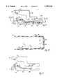
- FIG. 9illustrates a flexible circuit board 54 designed in accordance with the schematic of FIG. 8.
- the circuit boardis designed to fit into either a short battery pack case (low capacity) or a long battery pack case (high capacity).
- the type of battery pack (low or high capacity) being builtdetermines the contact rivet/washer attachment points used (described below).
- FIG. 10is a sectional view of a low capacity battery pack 34 (without the cells 10) showing the attachment points used when it is installed in a low capacity pack. As shown, the circuit board 54 is bent at two places so that the low capacity contact points 16A and 18A are positioned at the end of the case 34.
- a gap 56is formed between the negative current trace 14 and the sense resistor traces 50 and 52.
- the gaps 56create an open circuit between the trace 14 and the traces 50 and 52.
- the contact rivet 32 and washer 36are installed through the holes in contacts 18A or 18B (see FIGS. 5-7)
- the gap 56 between the trace 14 and the trace 50 or 52is bridged by the washer 36, shorting the traces together.
- FIG. 11is a diagram showing only the active circuit traces when the circuit board 54 is installed into a low capacity battery pack. As shown, the sense resistor R1 is connected to the sense resistor contact 24, while the sense resistor R2 is not. The charger, therefore, is able to identify the pack as a low capacity pack because of the resistance of sense resistor R1. The charger is then able to charge the pack in the proper manner.
- FIG. 13is a diagram showing only the active circuit traces when the circuit board 54 is installed into a high capacity battery pack. As shown, the sense resistor R2 is connected to the sense resistor contact 24, while the sense resistor R1 is not. The charger, therefore, is able to identify the pack as a high capacity pack because of the resistance of sense resistor R2. The charger is then able to charge the pack in the proper manner.
- a single flexible circuit board 54can be used in multiple applications which are different in their circuit requirements.
- the required electronic componentsare incorporated into the circuit automatically when the circuit board 54 is assembled to the mating components.
- a cost savingscan be realized through lower part procurement cost and reduced inventory and material handling costs.
- the present inventionmay include several alternatives to that described.
- a rigid circuit board designed for use with multiple applicationscould also be used.
Landscapes
- Chemical & Material Sciences (AREA)
- Chemical Kinetics & Catalysis (AREA)
- Electrochemistry (AREA)
- General Chemical & Material Sciences (AREA)
- Engineering & Computer Science (AREA)
- Microelectronics & Electronic Packaging (AREA)
- Manufacturing & Machinery (AREA)
- Battery Mounting, Suspending (AREA)
Abstract
Description
Claims (23)
Priority Applications (1)
| Application Number | Priority Date | Filing Date | Title |
|---|---|---|---|
| US09/124,740US5999410A (en) | 1998-07-29 | 1998-07-29 | Flexible circuit board configurable for use with different types of battery packs |
Applications Claiming Priority (1)
| Application Number | Priority Date | Filing Date | Title |
|---|---|---|---|
| US09/124,740US5999410A (en) | 1998-07-29 | 1998-07-29 | Flexible circuit board configurable for use with different types of battery packs |
Publications (1)
| Publication Number | Publication Date |
|---|---|
| US5999410Atrue US5999410A (en) | 1999-12-07 |
Family
ID=22416594
Family Applications (1)
| Application Number | Title | Priority Date | Filing Date |
|---|---|---|---|
| US09/124,740Expired - LifetimeUS5999410A (en) | 1998-07-29 | 1998-07-29 | Flexible circuit board configurable for use with different types of battery packs |
Country Status (1)
| Country | Link |
|---|---|
| US (1) | US5999410A (en) |
Cited By (16)
| Publication number | Priority date | Publication date | Assignee | Title |
|---|---|---|---|---|
| US6208524B1 (en)* | 1998-07-23 | 2001-03-27 | Micron Technology, Inc. | Electronic apparatus, battery powerable apparatus, and radio frequency communication device |
| US6285159B1 (en)* | 1998-07-11 | 2001-09-04 | Samsung Electronics Co., Ltd. | Portable computer usable with a specific battery pack or ordinary battery |
| US6423441B1 (en)* | 2000-01-12 | 2002-07-23 | Delphi Technologies, Inc. | Battery pack signal routing system |
| GB2375223A (en)* | 2001-05-03 | 2002-11-06 | Provector Ltd | Battery management system. |
| US6483275B1 (en)* | 1999-04-23 | 2002-11-19 | The Board Of Trustees Of The Univesity Of Illinois | Consumer battery having a built-in indicator |
| US20030027039A1 (en)* | 2001-07-31 | 2003-02-06 | Benson Morgan Rey | Battery pack having flexible circuit connector |
| US20060132095A1 (en)* | 2004-12-22 | 2006-06-22 | Shun-Yung Liao | Battery pack for a notebook PC |
| US20060195804A1 (en)* | 2004-09-22 | 2006-08-31 | Digi International Inc. | Method and apparatus for configurable circuitry |
| US20070194526A1 (en)* | 2002-12-10 | 2007-08-23 | Mitch Randall | System and method for providing power to an electronic device |
| US20080118825A1 (en)* | 2006-11-20 | 2008-05-22 | Heuisang Yoon | Battery pack and fabricating method thereof |
| US20090098750A1 (en)* | 2002-12-10 | 2009-04-16 | Mitch Randall | Reliable contact and safe system and method for providing power to an electronic device |
| US20120190252A1 (en)* | 2011-01-25 | 2012-07-26 | Pavlinsky Robert J | Rechargeable battery pack including low-resistance battery-pack interconnect |
| CN102615233A (en)* | 2011-01-28 | 2012-08-01 | 三洋电机株式会社 | Riveting apparatus and dismounting method for rivet |
| WO2015101267A1 (en) | 2013-12-31 | 2015-07-09 | Byd Company Limited | Signal collection and power connection assembly, power battery module and vehicle |
| CN104979517A (en)* | 2014-04-11 | 2015-10-14 | 三星Sdi株式会社 | Battery module |
| US12170450B2 (en) | 2020-11-20 | 2024-12-17 | Milwaukee Electric Tool Corporation | Systems and methods for identifying a battery pack for a battery pack powered power tool |
Citations (5)
| Publication number | Priority date | Publication date | Assignee | Title |
|---|---|---|---|---|
| US4680527A (en)* | 1986-08-06 | 1987-07-14 | Motorola, Inc. | Electrical battery including apparatus for current sensing |
| US5283511A (en)* | 1992-06-08 | 1994-02-01 | Thomas Keener | Rechargeable battery manager |
| US5635814A (en)* | 1995-02-16 | 1997-06-03 | International Components Corporation | Modular battery system having a pluggable charging module |
| US5754027A (en)* | 1996-07-08 | 1998-05-19 | Motorola, Inc. | Battery pack and associated charging system |
| US5905441A (en)* | 1996-09-10 | 1999-05-18 | Klee; Edward L. | Hand-held visual signaling device |
- 1998
- 1998-07-29USUS09/124,740patent/US5999410A/ennot_activeExpired - Lifetime
Patent Citations (5)
| Publication number | Priority date | Publication date | Assignee | Title |
|---|---|---|---|---|
| US4680527A (en)* | 1986-08-06 | 1987-07-14 | Motorola, Inc. | Electrical battery including apparatus for current sensing |
| US5283511A (en)* | 1992-06-08 | 1994-02-01 | Thomas Keener | Rechargeable battery manager |
| US5635814A (en)* | 1995-02-16 | 1997-06-03 | International Components Corporation | Modular battery system having a pluggable charging module |
| US5754027A (en)* | 1996-07-08 | 1998-05-19 | Motorola, Inc. | Battery pack and associated charging system |
| US5905441A (en)* | 1996-09-10 | 1999-05-18 | Klee; Edward L. | Hand-held visual signaling device |
Cited By (32)
| Publication number | Priority date | Publication date | Assignee | Title |
|---|---|---|---|---|
| US6285159B1 (en)* | 1998-07-11 | 2001-09-04 | Samsung Electronics Co., Ltd. | Portable computer usable with a specific battery pack or ordinary battery |
| US6208524B1 (en)* | 1998-07-23 | 2001-03-27 | Micron Technology, Inc. | Electronic apparatus, battery powerable apparatus, and radio frequency communication device |
| US6483275B1 (en)* | 1999-04-23 | 2002-11-19 | The Board Of Trustees Of The Univesity Of Illinois | Consumer battery having a built-in indicator |
| US6423441B1 (en)* | 2000-01-12 | 2002-07-23 | Delphi Technologies, Inc. | Battery pack signal routing system |
| GB2375223A (en)* | 2001-05-03 | 2002-11-06 | Provector Ltd | Battery management system. |
| US20030027039A1 (en)* | 2001-07-31 | 2003-02-06 | Benson Morgan Rey | Battery pack having flexible circuit connector |
| US6746797B2 (en)* | 2001-07-31 | 2004-06-08 | Delphi Technologies, Inc. | Battery pack having flexible circuit connector |
| US20090098750A1 (en)* | 2002-12-10 | 2009-04-16 | Mitch Randall | Reliable contact and safe system and method for providing power to an electronic device |
| US7982436B2 (en) | 2002-12-10 | 2011-07-19 | Pure Energy Solutions, Inc. | Battery cover with contact-type power receiver for electrically powered device |
| US20070194526A1 (en)* | 2002-12-10 | 2007-08-23 | Mitch Randall | System and method for providing power to an electronic device |
| US7932638B2 (en)* | 2002-12-10 | 2011-04-26 | Pure Energy Solutions, Inc. | Reliable contact and safe system and method for providing power to an electronic device |
| US20060195804A1 (en)* | 2004-09-22 | 2006-08-31 | Digi International Inc. | Method and apparatus for configurable circuitry |
| US7721238B2 (en) | 2004-09-22 | 2010-05-18 | Digi International Inc. | Method and apparatus for configurable printed circuit board circuit layout pattern |
| US20100175916A1 (en)* | 2004-09-22 | 2010-07-15 | Digi International Inc. | Method and Apparatus for Configurable Circuitry |
| US9767241B2 (en) | 2004-09-22 | 2017-09-19 | Digi International Inc. | Method and apparatus for printed circuit board with stiffener |
| US20060132095A1 (en)* | 2004-12-22 | 2006-06-22 | Shun-Yung Liao | Battery pack for a notebook PC |
| US8465868B2 (en) | 2006-11-20 | 2013-06-18 | Samsung Sdi Co., Ltd. | Battery pack and fabricating method thereof |
| US20080118825A1 (en)* | 2006-11-20 | 2008-05-22 | Heuisang Yoon | Battery pack and fabricating method thereof |
| EP1926160A1 (en)* | 2006-11-20 | 2008-05-28 | Samsung SDI Co., Ltd. | Battery pack and fabricating method thereof |
| US20120190252A1 (en)* | 2011-01-25 | 2012-07-26 | Pavlinsky Robert J | Rechargeable battery pack including low-resistance battery-pack interconnect |
| US8858270B2 (en)* | 2011-01-25 | 2014-10-14 | The Gillette Company | Rechargeable battery pack including low-resistance battery-pack interconnect |
| CN102615233B (en)* | 2011-01-28 | 2015-01-07 | 三洋电机株式会社 | Riveting apparatus and dismounting method for rivet |
| CN102615233A (en)* | 2011-01-28 | 2012-08-01 | 三洋电机株式会社 | Riveting apparatus and dismounting method for rivet |
| WO2015101267A1 (en) | 2013-12-31 | 2015-07-09 | Byd Company Limited | Signal collection and power connection assembly, power battery module and vehicle |
| EP3063822A4 (en)* | 2013-12-31 | 2017-01-04 | BYD Company Limited | Signal collection and power connection assembly, power battery module and vehicle |
| US9941502B2 (en) | 2013-12-31 | 2018-04-10 | Byd Company Limited | Signal collection and power connection assembly, power battery module and vehicle |
| CN104979517A (en)* | 2014-04-11 | 2015-10-14 | 三星Sdi株式会社 | Battery module |
| US20150295280A1 (en)* | 2014-04-11 | 2015-10-15 | Samsung Sdi Co., Ltd. | Battery module |
| KR20150117920A (en)* | 2014-04-11 | 2015-10-21 | 삼성에스디아이 주식회사 | Battery module |
| US10003105B2 (en)* | 2014-04-11 | 2018-06-19 | Samsung Sdi Co., Ltd. | Battery module having improved safety |
| CN104979517B (en)* | 2014-04-11 | 2019-08-23 | 三星Sdi株式会社 | Battery module |
| US12170450B2 (en) | 2020-11-20 | 2024-12-17 | Milwaukee Electric Tool Corporation | Systems and methods for identifying a battery pack for a battery pack powered power tool |
Similar Documents
| Publication | Publication Date | Title |
|---|---|---|
| US5999410A (en) | Flexible circuit board configurable for use with different types of battery packs | |
| US6972544B2 (en) | Apparatus for interconnecting battery cells in a battery pack and method thereof | |
| JP4910170B2 (en) | Battery pack with communication port | |
| US5197889A (en) | Electrical contact for battery package or similar device | |
| JP2769982B2 (en) | Battery pack for portable computers with minimal wiring | |
| US20140054278A1 (en) | Battery pack assembly with integrated heater | |
| US20040033717A1 (en) | Connecting device for connecting electrically a flexible printed board to a circuit board | |
| JPH02116228A (en) | Portable radio equipment | |
| US8691407B2 (en) | Battery pack | |
| EP1829135B1 (en) | Battery case | |
| JPH1012201A (en) | Pack battery with built-in printed board | |
| JPH11354089A (en) | Battery pack and method of manufacturing the same | |
| EP0722652A1 (en) | Device with external electrical interface | |
| KR102733883B1 (en) | Flexible printed circuit board and method of manufacturing the same | |
| US3401309A (en) | Arrangement of electrical circuits and multiple electrical components | |
| JPH11219834A (en) | Coil and clock | |
| US20240014516A1 (en) | Battery pack | |
| JP3695725B2 (en) | Battery and electronic device using the same | |
| JP2001102716A (en) | Electronic apparatus | |
| JP3617315B2 (en) | Battery pack | |
| JPH08203568A (en) | Secondary battery pack | |
| JPH1041U (en) | Battery package | |
| KR200157679Y1 (en) | Connection terminal and charging terminal assembly structure of mobile phone battery | |
| JPH07106001A (en) | Bus bar | |
| EP1337007A1 (en) | Intermediate board |
Legal Events
| Date | Code | Title | Description |
|---|---|---|---|
| AS | Assignment | Owner name:CENTURION INTERNATIONAL, INC., NEBRASKA Free format text:ASSIGNMENT OF ASSIGNORS INTEREST;ASSIGNOR:WEILER, ALLAN P.;REEL/FRAME:009571/0482 Effective date:19980723 | |
| STCF | Information on status: patent grant | Free format text:PATENTED CASE | |
| AS | Assignment | Owner name:CENTURION WIRELESS TECHNOLOGIES, INC., NEBRASKA Free format text:MERGER;ASSIGNOR:CENTURION INTERNATIONAL, INC.;REEL/FRAME:011284/0637 Effective date:20000920 Owner name:CENTURION WIRELESS TECHNOLOGIES, INC.,NEBRASKA Free format text:MERGER;ASSIGNOR:CENTURION INTERNATIONAL, INC.;REEL/FRAME:011284/0637 Effective date:20000920 | |
| FEPP | Fee payment procedure | Free format text:PAYOR NUMBER ASSIGNED (ORIGINAL EVENT CODE: ASPN); ENTITY STATUS OF PATENT OWNER: LARGE ENTITY Free format text:PAT HOLDER NO LONGER CLAIMS SMALL ENTITY STATUS, ENTITY STATUS SET TO UNDISCOUNTED (ORIGINAL EVENT CODE: STOL); ENTITY STATUS OF PATENT OWNER: LARGE ENTITY | |
| REFU | Refund | Free format text:REFUND - SURCHARGE, PETITION TO ACCEPT PYMT AFTER EXP, UNINTENTIONAL (ORIGINAL EVENT CODE: R2551); ENTITY STATUS OF PATENT OWNER: LARGE ENTITY | |
| FPAY | Fee payment | Year of fee payment:4 | |
| AS | Assignment | Owner name:CENTURION WIRELESS TECHNOLOGIES, INC., NEBRASKA Free format text:RELEASE OF SECURITY INTEREST;ASSIGNOR:PNC BANK, NATIONAL ASSOCIATION;REEL/FRAME:014215/0631 Effective date:20031121 | |
| FPAY | Fee payment | Year of fee payment:8 | |
| FEPP | Fee payment procedure | Free format text:PAYER NUMBER DE-ASSIGNED (ORIGINAL EVENT CODE: RMPN); ENTITY STATUS OF PATENT OWNER: LARGE ENTITY Free format text:PAYOR NUMBER ASSIGNED (ORIGINAL EVENT CODE: ASPN); ENTITY STATUS OF PATENT OWNER: LARGE ENTITY | |
| FPAY | Fee payment | Year of fee payment:12 | |
| AS | Assignment | Owner name:LAIRDTECHNOLOGEIS, INC., MISSOURI Free format text:MERGER;ASSIGNOR:CENTURION WIRELESS TECHNOLOGIES, INC.;REEL/FRAME:041929/0241 Effective date:20161231 | |
| AS | Assignment | Owner name:LAIRD CONNECTIVITY, INC., OHIO Free format text:ASSIGNMENT OF ASSIGNORS INTEREST;ASSIGNOR:LAIRD TECHNOLOGIES, INC.;REEL/FRAME:050464/0565 Effective date:20190331 |