US5999294A - Detachable antenna with optical port - Google Patents
Detachable antenna with optical portDownload PDFInfo
- Publication number
- US5999294A US5999294AUS08/816,568US81656897AUS5999294AUS 5999294 AUS5999294 AUS 5999294AUS 81656897 AUS81656897 AUS 81656897AUS 5999294 AUS5999294 AUS 5999294A
- Authority
- US
- United States
- Prior art keywords
- card
- communications
- optical
- peripheral apparatus
- antenna
- Prior art date
- Legal status (The legal status is an assumption and is not a legal conclusion. Google has not performed a legal analysis and makes no representation as to the accuracy of the status listed.)
- Expired - Lifetime
Links
- 230000003287optical effectEffects0.000titleclaimsabstractdescription214
- 238000004891communicationMethods0.000claimsabstractdescription153
- 230000002093peripheral effectEffects0.000claimsabstractdescription61
- 238000000034methodMethods0.000claimsdescription11
- 238000012545processingMethods0.000claimsdescription10
- 230000005540biological transmissionEffects0.000abstractdescription13
- 230000008901benefitEffects0.000abstractdescription4
- 230000000694effectsEffects0.000abstract1
- 239000004417polycarbonateSubstances0.000description22
- 230000008569processEffects0.000description6
- 230000006870functionEffects0.000description4
- 238000001514detection methodMethods0.000description3
- 239000000463materialSubstances0.000description3
- 238000001228spectrumMethods0.000description3
- 239000000758substrateSubstances0.000description3
- 238000010586diagramMethods0.000description2
- 238000002329infrared spectrumMethods0.000description2
- 230000007246mechanismEffects0.000description2
- 238000012986modificationMethods0.000description2
- 230000004048modificationEffects0.000description2
- 239000004033plasticSubstances0.000description2
- 230000004044responseEffects0.000description2
- 239000004065semiconductorSubstances0.000description2
- 229920004142LEXAN™Polymers0.000description1
- 239000004418LexanSubstances0.000description1
- 230000009471actionEffects0.000description1
- 239000000853adhesiveSubstances0.000description1
- 230000001070adhesive effectEffects0.000description1
- 238000007796conventional methodMethods0.000description1
- 238000013461designMethods0.000description1
- 238000009434installationMethods0.000description1
- 239000004973liquid crystal related substanceSubstances0.000description1
- 239000002184metalSubstances0.000description1
- 230000005404monopoleEffects0.000description1
- 230000005855radiationEffects0.000description1
- 230000001360synchronised effectEffects0.000description1
- 239000012780transparent materialSubstances0.000description1
Images


Classifications
- H—ELECTRICITY
- H04—ELECTRIC COMMUNICATION TECHNIQUE
- H04B—TRANSMISSION
- H04B10/00—Transmission systems employing electromagnetic waves other than radio-waves, e.g. infrared, visible or ultraviolet light, or employing corpuscular radiation, e.g. quantum communication
- H04B10/11—Arrangements specific to free-space transmission, i.e. transmission through air or vacuum
- H04B10/114—Indoor or close-range type systems
- H04B10/1143—Bidirectional transmission
Definitions
- the present inventionrelates generally to computer peripheral devices having a detachable portion, and more particularly to a peripheral device having a detachable portion with an optical port.
- wireless mobile devicessuch as personal data assistants (PDA's), electronic planners, etc.
- PDA'spersonal data assistants
- electronic plannersetc.
- the wireless nature of these devicesprovides the user with the ability to move freely from one location to another without the hindrance of cords and other hardwired connections.
- userscan enjoy the benefits of personalized computing power while traveling or simply commuting from one location to another.
- wireless mobile devicesare fairly self contained, there are many instances when they will need to interface with other devices such as a desk top computer or a Local Area Network (LAN). For instance, after returning from a business trip, a user may wish to download all information stored in their PDA to their office desk top computer. Additionally, connections between the mobile device and a LAN may often be necessary to print documents to a printer connected to the LAN.
- LANLocal Area Network
- a bi-directional optical communication porte.g., a bi-directional infrared (IR) port which complies with published infrared data association (IRDA) standards.
- IRinfrared
- IRDApublished infrared data association
- host devicese.g., desk top computers, lap top computers, mobile terminals, etc.
- host devicese.g., desk top computers, lap top computers, mobile terminals, etc.
- wires associated with optical transceivers connected to the host device or LANoften come in the way of a user.
- the present inventionrelates to a peripheral apparatus which enables users to communicate with a host device via radio as well as optical transmission substantially simultaneously.
- the peripheral apparatusis particularly useful in that an available com port does not have to be solely dedicated for optical communications.
- the peripheral apparatusavoids the problems associated with employing external wires to connect an optical transceiver to the host device.
- the present inventionaffords a user the benefit of simply attaching the peripheral apparatus to the host device so that is capable of communicating via RF and optics substantially simultaneously.
- the peripheral apparatusincludes a PC card having a selectively detachable antenna.
- the detachable antennaincludes at least one radio antenna and an optical port (i.e., optical device).
- optical porti.e., optical device.
- the peripheral apparatusis capable of communicating via RF and optical communications.
- the peripheral apparatusemploys a unique polling scheme which affords a host device substantially simultaneous radio and optical communications with one or more other devices.
- a peripheral apparatusincluding: a PC card including circuitry for handling radio frequency (RF) communications and optical communications; and an antenna apparatus, selectively detachable from the PC card, including at least one antenna element operative in combination with the PC card for conducting the RF communications; and an optical device operative in combination with the PC card for conducting the optical communications.
- RFradio frequency
- an antenna apparatusselectively detachable from a PC card
- the PC cardincluding circuitry for handling RF communication and optical communication
- the antenna apparatusincluding: at least one RF antenna operative in combination with the PC card for conducting RF communications; and an optical device operative in combination with the PC card for conducting optical communication.
- a mobile unit in combination with a peripheral apparatusincluding: a mobile unit, including: a housing; electronic circuitry within the housing, the electronic circuitry being able to carry out operations of the mobile unit; and a peripheral apparatus, comprising: a PC card including circuitry for handling radio frequency (RF) communications and optical communications; an antenna apparatus, selectively detachable from the PC card, including at least one antenna element operative in combination with the PC card for conducting the RF communications; and an optical device operative in combination with the PC card for conducting the optical communications.
- RFradio frequency
- a method for providing RF communications and optical communications to a mobile unitcomprising the steps of: attaching a peripheral apparatus to the mobile terminal, the peripheral apparatus including: a PC card including circuitry for handling radio frequency (RF) communications and optical communications; and a detachable antenna, the detachable antenna including an optical device for optical communications; using the circuitry including in the PC card to periodically poll the optical device to determine if optical communications are being transmitted to the mobile unit; and disabling the radio device and enabling the optical device upon determining that optical communications are being transmitted to the mobile unit.
- RFradio frequency
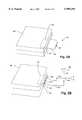
- FIG. 1is a perspective view of a PCMCIA card with a detachable antenna in accordance with the present invention
- FIG. 2Ais a perspective view of the PCMCIA card with the detachable antenna inserted in a notebook computer PCMCIA card slot in accordance with the present invention
- FIG. 2Bis a perspective view of the PCMCIA card of FIG. 2A with the antenna detached and an external antenna connected thereto in accordance with the present invention
- FIG. 3is an exploded view of the PCMCIA card and detachable antenna (with the antenna element detached) in accordance with the present invention
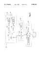
- FIG. 4is a block diagram representing the basic structure of an optics section, modem and RF section in accordance with the present invention
- FIG. 5is a perspective view of an antenna element included within the detachable antenna in accordance with the present invention.
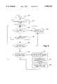
- FIG. 6is a flow chart representing the operation of the PCMCIA card and the detachable antenna in accordance with the present invention.
- PCMCIA cardand "PC card” are employed interchangeably throughout the specification and claims.
- the wireless network adapter card 20includes a PCMCIA card 22 and a detachable antenna 24.
- the PCMCIA card 22includes a card-shaped housing 30 having a top cover 30a and a bottom cover 30b. Included within the housing 30 is an integrated circuit (IC) board 32 (see FIG. 3).
- the housing 30is made of plastic or metal but includes RF shielding material to minimize RF leakage into the surrounding area.
- the top and bottom covers 30a and 30bare ultrasonically welded together and or secured together by small screws, adhesives or other fastening means as is conventional.
- the detachable antenna 24includes a card-shaped housing 36 having a top cover 36a and a bottom cover 36b which form a radome for a pair of patch 30 type diversity antennas 40, 42 housed therein (see FIG. 5).
- the housing 36is made of a plastic radome material such as Lexan which allows radio frequency (RF) energy to pass therethrough with little or no attenuation while still providing structural support and rigidity.
- the top and bottom covers 36a, 36bmay be ultrasonically welded together or otherwise joined according to conventional techniques.
- the detachable antenna 24also includes an optics window 46. As will be discussed in greater detail below, the optics window 46 provides for the transmission and reception of light waves carrying data (e.g., infrared).
- the optics window 46is preferably made of suitable transparent material for infrared radiations at wavelengths of interest. Any suitable type of window 46 may be used to carry out the present invention.
- the detachable antenna 24is selectively detachable from the PCMCIA card 22 by way of a number of frictional connections. More particularly, an edge 60 of the detachable antenna 24 includes a pair of wedge shape tines 62. The tines 62 are designed to mate in forced frictional engagement with a corresponding pair of wedge shape channels 64 located on an edge 70 of the PCMCIA card 22. Furthermore, the detachable antenna 24 includes a triad of male plug-type connectors 72 which protrude from the edge 60 of the antenna housing 36. The connectors 72a provide respective RF connections between the antenna element within the detachable antenna 24 as discussed more fully below and the integrated circuit board 32 within the PCMCIA card 22.
- the connector 72bprovides an optical connection between the optical section within the detachable antenna 24 as discussed more fully below and the integrated circuit board 32 within the PCMCIA card 22.
- the connectors 72are designed to mate with corresponding female-type connectors 74 located flush with the edge 70 of the PCMCIA card 22.
- the connectors 74ain turn are connected to a radio (i.e., RF section) 80 within the PCMCIA card 22.
- the radio 80is tied to a modem 82 (FIG. 3).
- the connector 74bis connected directly to the modem 82.
- the connectors 72 and 74are preferably of a type which provides both electrical and mechanical connection between the detachable antenna 24 and the PCMCIA card 22 for a secure fit in combination with the tines 62.
- the connectors 72 and 74preferably include a snap type mechanism or the like which provides for a releasable locking action between the antenna 24 and the PCMCIA card 22 when the tines 62 are fully engaged within the channels 64 and the edges 60 and 70 are substantially flush.
- the detachable antenna 24affords for quick and easy installation to the PC card 22 to afford a user with the ability to communicate via radio and optical communications.
- the usersince RF antennas as wells as optics are enclosed in the detachable antenna 24, the user is freed from having to dedicate an available com port of a host device (not shown) to communicate optically.
- the useris freed from the nuisance associated with loose wires typical to modular optics sections that are coupled a the host device such as a desk top computer.
- the present inventionaffords for a user to simply snap the detachable antenna 24 to the PC card 22 so that the host device can communicate via either RF and optical communications.
- the present inventionemploys a unique polling protocol which provides for the host device to communicate via RF and optics substantially simultaneously.
- FIGS. 2A and 2Bthe network adapter card 20 is shown, for example, as used in a notebook type personal computer 100.
- FIG. 2Aillustrates the use of the card 20 with the antenna 24 attached to the PCMCIA card 22.
- the PCMCIA card 22is inserted into a PCMCIA card slot 102 as is conventional.
- the antenna 24extends outwardly from the computer 100 in order to transmit and receive radio and/or optical communications based on operations controlled by the computer 100.
- the antenna 24is detached from the PCMCIA card 22 in the manner noted above.
- the connectors 74 on the edge 70are exposed when the PCMCIA card 22 is inserted in the slot 102 as shown in FIG. 2B.
- Corresponding connectors on the ends of cables 110, 112are utilized to connect auxiliary antennas 120 to the radio within the PCMCIA card 22.
- the antennas 120are made up of two separate elements 122 and 124 which are oriented orthogonally as is known.
- the PCMCIA card 22has housed therein an IC board 32 which includes a top side 150 and a bottom side 152.
- the top 150 and bottom 152 sides of the IC board 32contain electronic circuitry which enables the PCMCIA card 22 to communicate wirelessly via the detachable antenna 24.
- the IC board 32includes the modem 82 which controls both an RF section 80 and an optics section 160.
- the modem 82preferably is an MSM 7730 Wireless LAN Modem Chip made by Oki Semiconductor of Japan. However, it is to be understood that any suitable modem or device may be employed to carry out the present invention.
- the modem 82will periodically poll the optics section 160 to determine if any optical information is being transmitted to the host device.
- the optics section 160includes an optical transceiver 180 (FIG. 4) and an optical window 46.
- the optical transceiver 180includes an optical transmitter 182 (FIG. 4) for transmitting data optically (e.g., via an LED).
- the optical transceiver 180also includes an optical receiver 184 for receiving data optically (e.g., via a photo diode).
- the optical transceiver 180performs its optical communications via infrared light.
- suitable optical mediumsi.e., light of other frequencies
- the optical window 46provides for optical communications by permitting light waves containing data to be input and output to the detachable antenna 24 via the optical window 46.
- the modem 82may periodically poll the optical section. If optical transmission is detected, the modem 82 temporarily stops processing RF communication and instead handles the optical communication.
- the modem 82is also connected to an input/output (I/0) port 190 which is coupled to a multi-terminal connector 192.
- the connector 192enables the card 20 to be connected to a corresponding connector in the PCMCIA card slot 102 of the host device (FIGS. 2A-2B) as is conventional.
- Each of the connectors 74ais connected to the RF section 80 in order that radio signals to and from the RF section are transmitted/received by whichever type antenna is connected to the connectors 72a.
- each tine 62is made up of a half wedge shape tine 62a and 62b extending from the top and bottom covers 36a and 36b, respectively.
- the corresponding wedge shape channels 64are made up of half wedge shape channels 64a and 64b in the walls 236a and 236b of the top and bottom covers 30a and 30b, respectively.
- the top cover 36a of the detachable antenna housing 36includes two semicircular recesses (not shown) and one semisquare recess (not shown) which combined with the semicircular recesses 250a and the semisquare recess 250b, respectively, in the bottom cover 36b form apertures through which the connectors 72 (FIG. 1) extend.
- the top cover 30a of the PCMCIA card 22includes semicircular recesses 252a which combined with the semicircular recesses 252b in the bottom cover 30b form apertures through which the connectors 74a are exposed.
- the top cover 30a of the PCMCIA card 22also includes semisquare recess 253a which combined with the semisquare recess 253b in the bottom cover 30b form apertures through which the connector 74b are exposed.
- the connector 74bties into the connector 72b which is coupled to the optics section 160.
- the top cover 30aalso includes a slot forming recess (not shown) which combined with the slot forming recess 256 in the bottom cover 30b forms a slot 258 (shown in phantom in FIG. 1) which allows the card 20 to be connected to a computer via a PCMCIA card slot.
- the optical transceiver 180includes a programmable serial interface device (SID) 300 such as a 16550 or 16450 UART (universal asynchronous receiver and transmitter) from National Semiconductor.
- SIDprogrammable serial interface device
- Technically equivalent interface devicesinclude but are not limited to universal synchronous and asynchronous receivers and transmitters (USARTs), asynchronous communications interface adapters (ACIAs), serial input/output (SIO) devices, data link controllers, multiple protocol communications controllers and serial communications controllers.
- the serial interface device 300receives data from the host device (typically in parallel format) through a serial output location and transmits an equivalent serial bit stream to an encoder 302.
- the encoder 302transforms the bits into electrical pulses that occupy less than the full bit time and passes them to the optical transmitter 182 such as an infrared transmitter.
- the optical transmitter 182transforms the electrical pulses into infrared light pulses for example and broadcasts the light pulses at a selected baud rate.
- the receiving side of the optical transceiver 180includes the optical receiver 184 such as an IR receiver that receives similar light pulses from a transmitter from an another device and transforms them into electrical pulses.
- the optical receiver 184passes these electrical pulses to a decoder 318 for decoding the electrical pulses into a serial bit stream.
- the decoder 318in turn routes the bit stream to a serial input location on the serial interface device 300 for communication to the modem 82.
- the optical transceiver 180preferably operates in half-duplex mode (ile., with only the optical transmitter 182 or optical receiver 184 active at any given time) in order to prevent the optical transceiver 180 from receiving the data it transmits. However, it will be appreciated that with additional shielding, the optical transceiver 180 could be operated in full-duplex mode (i.e., both the optical transmitter 182 and the optical receiver 184 simultaneously active).
- serial interface 300may include or be coupled to a programmable baud rate generator (not shown) for transmitting the serial bit stream at selectable baud rates.
- the serial interface 300also may include an SID clock (not shown) that runs at a multiple of the baud rate so as to clock the encoder 302 and decoder 318. Accordingly, an operator of the host device could selectably control the optical transmission rate.
- the modemis also tied to the RF section 80 which provides for radio communications with another device.
- the RF section 80includes a radio receiver 320 and a radio transmitter 324 for receiving and transmitting radio signals in connection with the operation of the host device and the detachable antenna 24.
- the RF section 80is tied to the patch antennas 40 and 42 located within the detachable antenna 24.
- the RF section 80 and the optics section 180are coupled to a processor 350 tied to the modem 82.
- the processor 350is responsible for controlling the overall operation of the modem 82, the RF section 80 and the optics section 180. For example, the processor 350 controls the operation of the modem 82 with respect to discriminating between incoming radio and optical signals.
- the processor 350is also responsible for enabling and disabling the RF section 80 and the optics section 180, respectively. In addition, the processor 350 controls the operation of the RF section 80 and the optics section 180 with respect to the information received and transmitted by each section, respectively. Generally speaking, the processor 350 is programmed to control and to operate the various components relating to the modem 82, the RF section 80 and the optics section 180 in order to carry out the various functions described herein.
- a memory 352tied to the processor 350, stores program code executed by the processor 350 for carrying out the functions described herein.
- the actual code for performing such functionscould be easily programmed by a person having ordinary skill in the art of computer programming in any of a number of conventional programming languages based on the disclosure herein. Consequently, further detail as to the particular code has been omitted for sake of brevity.
- the memory 352also serves as a storage medium for storing information input by the user and/or received from or transmitted by either of the RF section 80 and the optics section 180.
- the memory 353may include both volatile and non-volatile memory.
- FIG. 5illustrates an exemplary antenna element 360 which fits within the housing 36 of the detachable antenna 24.
- the antenna element 360 in this embodimentincludes separate patch antenna elements 40 and 42 formed on a substrate 362.
- the substrate 362is sized to fit within the housing 36 and rest upon the standoffs 200 as illustrated in FIG. 3 discussed above.
- Each patch antenna element 40, 42is connected to a corresponding one of the connectors 72a.
- the connectors 72aare each mounted securely to the substrate 362.
- the antenna element 360could include monopole, dipole, or other antennas, as will be appreciated.
- the modem 82will periodically poll the optical transceiver 180 in the detachable antenna 24 to see if any optical information is being transmitted to the host device. For example, the modem 82 may attempt to poll the optical transceiver 180 every 300-400 msec. If optical transmission is detected, the modem 82 temporarily stops processing RF communication and instead handles the optical communication.
- the modem 82is typically switched to receive and transmit data over the RF spectrum via the RF section 80. However, upon detection of optical transmission thereto, the modem 82 switches to the optical section 160 so that data can be received over the optical spectrum (e.g., IR spectrum) via the optical receiver 184. Similarly, when a user of the host device decides to transmit data optically, the modem 82 likewise disables the RF transmitter 324 and enables the optical transmitter 182 so that data can be transmitted over the optical spectrum (e.g., IR spectrum) via the optical transmitter 182.
- the modem 82likewise disables the RF transmitter 324 and enables the optical transmitter 182 so that data can be transmitted over the optical spectrum (e.g., IR spectrum) via the optical transmitter 182.
- the modem 82will disable the optical transceiver 180 and enable the RF section 80, which is its default state.
- the modem 82defaults to communicating via the RF section 80. However, the modem 82 will periodically poll the optical transceiver 180 to determine if any optical information is being transmitted to the host device. In the preferred embodiment, the modem 82 will poll the optical transceiver 180 at least once per second. However, if the modem 82 is currently handling RF communication, then the modem 82 will suspend its polling until the RF communication has been completed. In other words, the ongoing RF communication takes precedence over the optical polling. Similarly, if the modem 82 is currently handling optical communication, the modem 82 will complete the optical communication before returning to the RF mode.
- the modem 82Only if no RF communication has occurred within the last 20 msec will the modem 82 continue its next poll in the poll cycle. If RF communication is currently occurring, the modem 82 will wait until all communication has subsided for 20 msec, and then immediatedly poll the optical transceiver 180 again. If during a poll of the optical transceiver 180 the modem 82 detects optical communication, the modem 82 will immediately handle the optical communication until completed.
- the modem 82can determine if optical communications are be transmitted to the host device in a variety of ways. For example, the modem 82 may determine if an optical transmission is occurring by simply sensing a signal on line 380 (FIG. 3) from the optical section 160.
- Line 380is housed in a conduit 382 (shown in phantom) which may be made of any material suitable for isolating the signal line 380 from noise.
- Line 380includes several sub-lines (e.g., a control line, a voltage line, a ground line, a transmit line, a receive line, etc.) for facilitating the optical communications.
- the modem 82could include an optical detector (not shown) such as for example an IR detector which detects an IR signal over an RF signal by resonating the incoming signal at a detection frequency.
- an optical detectorsuch as for example an IR detector which detects an IR signal over an RF signal by resonating the incoming signal at a detection frequency.
- the modem 82can handle only one type of communication at any given time. Accordingly, when the modem 82 is serving the optical section 160, any RF communication directed to the radio 80 in the PCMCIA card will not be received. Thus, the transmitting device will not receive an acknowledgment and would simply later transmit the same RF message. As optical dumps are very quick, there typically will not be any significant down time for the RF section 80. Thus, the radio card 20 will work substantially the same as it does without the optical section 46 with the exception of the few moments when optical communication is occurring.
- the present inventionprovides for communicating via both radio and optical communications substantially simultaneously.
- the present inventioncould be employed in a retail store environment where shelf tags are being used.
- Shelf tag systemsare known in which the so-called “shelf tags" contain means for programming information into small display devices which are attached to front edges of merchandise storage shelves. The devices or tags would then retain the programmed data which may be acquired by the reader in the radio card 20, for example.
- Informationmay be communicated between the shelf tag and the host device by various means including radio frequency and/or optical transmission. Information may be communicated via optical readers in the data and communication terminal as read from liquid crystals, or by other communication such as infrared optical, or low power RF data messages.
- a problem with shelf tag systems which update the shelf tags via RF communicationsis that neighboring shelf tags (which are not intended to be updated) may inadvertently be updated with incorrect information due to receiving RF signals not intended for them.
- the present inventioncan be employed to avoid such problems in that the moblie terminal (i.e., host device) being used to update the shelf tags could be updated from a host computer (not shown) via radio communications and the mobile terminal could update the proper shelf tags optically. Since optical transmissions are more focused and guided, inadvertent updating of neighboring shelf tags could be avoided. It should be appreciated that there are numerous such applications of the present invention.
- step 400power is first applied to the PC card 20 by way of it being inserted (i.e., connected) to the host device as is conventional.
- the modem 82is activated.
- step 410the RF section 80 is enabled by the modem 82.
- the RF section 80 being enabledis generally the default arrangement for the modem 82 since the host device primarily receives radio signals as opposed to optical signals.
- step 420the processor 350 determines if there is any RF communications being transmitted to the mobile device or being transmitted by the mobile device. If yes, the processor 350 proceeds to step 430 where it processes the RF communications.
- step 430After the RF communications are processed in step 430, the process returns to step 420. If in step 420 there is no RF communications being transmitted to the host device or being transmitted by the host device, the processor 350 advances to step 440. In step 440, the processor 350 waits a predetermined period of time and then determines again in step 450 if there is RF communications being transmitted to the mobile device or being transmitted by the mobile device. If yes, the processor 350 returns to step 430 where it processes the RF information as described above.
- step 460determines in step 460 if there is optical communications being transmitted to the host device or being transmitted by the host device. If yes, the processor 350 moves to step 470 where it disables the RF section 80 and enables the optics section 180. Then, the processor 350 proceeds to step 480 where the processor 350 processes the optical communication until complete. Once the processing of the optical communication is complete, the processor 350 in step 490 disables the optics section 180 and reenables the RF section 80. After the RF section 80 is re-enabled in step 490, the process returns to step 420. If in step 460, the processor 350 determines that there is no optical communications being transmitted to the mobile device or being transmitted by the mobile device, the process returns to step 420.
- the present inventionaffords for a peripheral apparatus which provides for a host device to communicate via radio and optical communications.
- the unique polling protocolmakes possible substantially simultaneous communications using radio and optical mediums.
- the radio card 20provides for a host device to communicate optically without having to designate a free com port.
- the present inventionmakes possible a device which can employ a com port already in use for radio communications to be shared so that optical communications can be effected as well.
- the integrated design of the peripheral antennaavoids the need for having to connect cumbersome wires in order to couple an optical device to the host device.
- the present inventioncould employ an interrupt driven protocol whereby the optical device 160 could provide an interrupt when an optical signal is being transmitted to the host device.
- the present inventioncould disable the RF section 80 and enable the optical section 160 in the manner described above.
- the optical device 160could provide another interrupt when the optical transmission from the other device is complete.
- the present inventionin response to the second interrupt, could enable the RF section 80 and disable the optical section 160 in the manner described above.
- the PC card 20could sense when the optical transmissions from the other device is complete in any of a number of manners and enable the RF section 80 and disable the optical section 160 in the manner described above.
- the radio card 20may include any combination of diverse functions elements. For instance, extended data memory capacity or a telephone modem could be included as part of the radio card of the peripheral apparatus.
- a buffer(not shown) could be employed in accordance with the present invention.
- the buffercould be either external or internal to the modem 82.
- the buffercould store RF data that is being transmitted to the mobile terminal during an optical transmission session. More specifically, if the modem 82 is currently handling optical communication and during this period RF communication is being transmitted to the mobile device, the RF data could be stored in the buffer. After the modem 82 has completed its optical data transaction, it could retrieve the RF data stored in the buffer. In this manner, the device transmitting the RF data would not have to retransmit the RF data, and the chance for losing data would be reduced.
Landscapes
- Physics & Mathematics (AREA)
- Electromagnetism (AREA)
- Engineering & Computer Science (AREA)
- Computer Networks & Wireless Communication (AREA)
- Signal Processing (AREA)
- Mobile Radio Communication Systems (AREA)
- Optical Communication System (AREA)
Abstract
Description
Claims (34)
Priority Applications (1)
| Application Number | Priority Date | Filing Date | Title |
|---|---|---|---|
| US08/816,568US5999294A (en) | 1997-03-13 | 1997-03-13 | Detachable antenna with optical port |
Applications Claiming Priority (1)
| Application Number | Priority Date | Filing Date | Title |
|---|---|---|---|
| US08/816,568US5999294A (en) | 1997-03-13 | 1997-03-13 | Detachable antenna with optical port |
Publications (1)
| Publication Number | Publication Date |
|---|---|
| US5999294Atrue US5999294A (en) | 1999-12-07 |
Family
ID=25220994
Family Applications (1)
| Application Number | Title | Priority Date | Filing Date |
|---|---|---|---|
| US08/816,568Expired - LifetimeUS5999294A (en) | 1997-03-13 | 1997-03-13 | Detachable antenna with optical port |
Country Status (1)
| Country | Link |
|---|---|
| US (1) | US5999294A (en) |
Cited By (36)
| Publication number | Priority date | Publication date | Assignee | Title |
|---|---|---|---|---|
| US6160647A (en)* | 1997-08-09 | 2000-12-12 | Stratos Lightwave, Inc. | Optoelectronic transmitter with improved control circuit and laser fault latching |
| US20010006902A1 (en)* | 2000-01-05 | 2001-07-05 | Takafumi Ito | IC card with radio interface function, antenna module and data processing apparatus using the IC card |
| US6286063B1 (en)* | 1998-06-08 | 2001-09-04 | Sonigistix Corporation | Microprocessor-controlled broadcast receiver embedded in an external peripheral with digital communications interface for bi-directional communication with a computer remotely located |
| WO2001067040A1 (en)* | 2000-03-03 | 2001-09-13 | Thomas Truett S | Battery module transceiver for extending the range of an infrared remote controller |
| US6400480B1 (en) | 1999-07-13 | 2002-06-04 | Truett S. Thomas | Battery module transceiver for extending the range of an infrared remote controller |
| US6477391B1 (en)* | 1998-11-10 | 2002-11-05 | Nissan Motor Co., Ltd. | Mobile telephone holding device |
| US20030036391A1 (en)* | 2000-08-25 | 2003-02-20 | Xemplix, Ltd. | Relating to information delivery |
| US20030092396A1 (en)* | 2001-11-09 | 2003-05-15 | David Fifield | Wireless network card with antenna selection option |
| US6577419B1 (en)* | 1998-12-18 | 2003-06-10 | Christopher J. Hall | Optical-frequency communications system for aircraft |
| US20040037566A1 (en)* | 2000-01-13 | 2004-02-26 | Lightpointe Communications, Inc. | Hybrid wireless optical and radio frequency communication link |
| US6782208B1 (en)* | 1999-11-16 | 2004-08-24 | Motorola, Inc. | Wireless communication device and method having coordinated primary and secondary transmitters |
| US6830181B1 (en)* | 1998-02-09 | 2004-12-14 | Intermec Ip Corp. | Combined optical and radio frequency tag reader |
| US20050169585A1 (en)* | 2002-06-25 | 2005-08-04 | Aronson Lewis B. | XFP transceiver with 8.5G CDR bypass |
| US20050282416A1 (en)* | 2004-06-15 | 2005-12-22 | Leif Malmberg | Electrical module |
| US20060034311A1 (en)* | 2004-08-13 | 2006-02-16 | Kyocera Wireless Corp. | Mobile broadband modem and related access sharing technique |
| US20070047625A1 (en)* | 2005-08-31 | 2007-03-01 | Klomsdorf Armin W | Multi-mode wireless communication device and method |
| WO2007070855A3 (en)* | 2005-12-14 | 2008-02-14 | Welch Allyn Inc | Medical device wireless adapter |
| US7437079B1 (en) | 2002-06-25 | 2008-10-14 | Finisar Corporation | Automatic selection of data rate for optoelectronic devices |
| US7463863B1 (en)* | 1997-08-08 | 2008-12-09 | Agere Systems, Inc. | Wireless terminal adapted for detachably connecting with a radio |
| US7477847B2 (en) | 2002-09-13 | 2009-01-13 | Finisar Corporation | Optical and electrical channel feedback in optical transceiver module |
| US7483673B2 (en) | 2003-11-24 | 2009-01-27 | Seoby Electronics Co., Ltd. | Power line communications using battery devices |
| US7486894B2 (en) | 2002-06-25 | 2009-02-03 | Finisar Corporation | Transceiver module and integrated circuit with dual eye openers |
| US20090060515A1 (en)* | 2007-09-04 | 2009-03-05 | Sony Corporation | Remote controlling system, electronic device, and controlling method |
| US7561855B2 (en) | 2002-06-25 | 2009-07-14 | Finisar Corporation | Transceiver module and integrated circuit with clock and data recovery clock diplexing |
| US20100026498A1 (en)* | 2008-07-29 | 2010-02-04 | David Bellows | Method and System for Adapting a Mobile Computing Device with an RFID Antenna |
| US7664401B2 (en)* | 2002-06-25 | 2010-02-16 | Finisar Corporation | Apparatus, system and methods for modifying operating characteristics of optoelectronic devices |
| US20110084886A1 (en)* | 2006-08-30 | 2011-04-14 | Nec Corporation | Portable apparatus |
| US20130294456A1 (en)* | 2009-12-04 | 2013-11-07 | Cradlepoint, Inc. | Security enclosure for a router |
| US20170093491A1 (en)* | 2015-09-30 | 2017-03-30 | Osram Sylvania Inc. | Adaptive baud rate in light-based communication |
| US9742492B2 (en) | 2015-12-30 | 2017-08-22 | Surefire Llc | Systems and methods for ad-hoc networking in an optical narrowcasting system |
| US9853740B1 (en) | 2017-06-06 | 2017-12-26 | Surefire Llc | Adaptive communications focal plane array |
| US10236986B1 (en) | 2018-01-05 | 2019-03-19 | Aron Surefire, Llc | Systems and methods for tiling free space optical transmissions |
| US10250948B1 (en) | 2018-01-05 | 2019-04-02 | Aron Surefire, Llc | Social media with optical narrowcasting |
| US10439287B2 (en)* | 2017-12-21 | 2019-10-08 | Nxgen Partners Ip, Llc | Full duplex using OAM |
| US10473439B2 (en) | 2018-01-05 | 2019-11-12 | Aron Surefire, Llc | Gaming systems and methods using optical narrowcasting |
| US10749607B2 (en)* | 2017-07-06 | 2020-08-18 | Tyco Fire & Security Gmbh | Integrated infra-red receiver and low/high-frequency receiver in portable transponder device |
Citations (10)
| Publication number | Priority date | Publication date | Assignee | Title |
|---|---|---|---|---|
| US5075792A (en)* | 1989-03-20 | 1991-12-24 | Hewlett-Packard Company | Low power optical transceiver for portable computing devices |
| US5081543A (en)* | 1990-01-12 | 1992-01-14 | Siemens Aktiengesellschaft | Medical diagnostics installation with multiple, wireless control signal transmission channels |
| US5218187A (en)* | 1990-01-18 | 1993-06-08 | Norand Corporation | Hand-held data capture system with interchangeable modules |
| US5343319A (en)* | 1993-06-14 | 1994-08-30 | Motorola, Inc. | Apparatus for adapting an electrical communications port to an optical communications port |
| US5495358A (en)* | 1992-11-23 | 1996-02-27 | Hewlett-Packard Company | Optical transceiver with improved range and data communication rate |
| US5585953A (en)* | 1993-08-13 | 1996-12-17 | Gec Plessey Semiconductors, Inc. | IR/RF radio transceiver and method |
| US5668977A (en)* | 1994-03-25 | 1997-09-16 | Advanced Micro Devices, Inc. | Dockable computer system capable of electric and electromagnetic communication |
| US5781321A (en)* | 1995-03-02 | 1998-07-14 | Nec Corporation | Portable electronic apparatus having a plurality of infrared ports |
| US5812293A (en)* | 1996-12-31 | 1998-09-22 | Yen; Kerl | A/V signal transmission remote control system |
| US5877882A (en)* | 1996-06-13 | 1999-03-02 | International Business Machines Corp. | Optical docking station |
- 1997
- 1997-03-13USUS08/816,568patent/US5999294A/ennot_activeExpired - Lifetime
Patent Citations (10)
| Publication number | Priority date | Publication date | Assignee | Title |
|---|---|---|---|---|
| US5075792A (en)* | 1989-03-20 | 1991-12-24 | Hewlett-Packard Company | Low power optical transceiver for portable computing devices |
| US5081543A (en)* | 1990-01-12 | 1992-01-14 | Siemens Aktiengesellschaft | Medical diagnostics installation with multiple, wireless control signal transmission channels |
| US5218187A (en)* | 1990-01-18 | 1993-06-08 | Norand Corporation | Hand-held data capture system with interchangeable modules |
| US5495358A (en)* | 1992-11-23 | 1996-02-27 | Hewlett-Packard Company | Optical transceiver with improved range and data communication rate |
| US5343319A (en)* | 1993-06-14 | 1994-08-30 | Motorola, Inc. | Apparatus for adapting an electrical communications port to an optical communications port |
| US5585953A (en)* | 1993-08-13 | 1996-12-17 | Gec Plessey Semiconductors, Inc. | IR/RF radio transceiver and method |
| US5668977A (en)* | 1994-03-25 | 1997-09-16 | Advanced Micro Devices, Inc. | Dockable computer system capable of electric and electromagnetic communication |
| US5781321A (en)* | 1995-03-02 | 1998-07-14 | Nec Corporation | Portable electronic apparatus having a plurality of infrared ports |
| US5877882A (en)* | 1996-06-13 | 1999-03-02 | International Business Machines Corp. | Optical docking station |
| US5812293A (en)* | 1996-12-31 | 1998-09-22 | Yen; Kerl | A/V signal transmission remote control system |
Cited By (80)
| Publication number | Priority date | Publication date | Assignee | Title |
|---|---|---|---|---|
| US7463863B1 (en)* | 1997-08-08 | 2008-12-09 | Agere Systems, Inc. | Wireless terminal adapted for detachably connecting with a radio |
| US6160647A (en)* | 1997-08-09 | 2000-12-12 | Stratos Lightwave, Inc. | Optoelectronic transmitter with improved control circuit and laser fault latching |
| US6830181B1 (en)* | 1998-02-09 | 2004-12-14 | Intermec Ip Corp. | Combined optical and radio frequency tag reader |
| US6286063B1 (en)* | 1998-06-08 | 2001-09-04 | Sonigistix Corporation | Microprocessor-controlled broadcast receiver embedded in an external peripheral with digital communications interface for bi-directional communication with a computer remotely located |
| US6477391B1 (en)* | 1998-11-10 | 2002-11-05 | Nissan Motor Co., Ltd. | Mobile telephone holding device |
| US6577419B1 (en)* | 1998-12-18 | 2003-06-10 | Christopher J. Hall | Optical-frequency communications system for aircraft |
| US6400480B1 (en) | 1999-07-13 | 2002-06-04 | Truett S. Thomas | Battery module transceiver for extending the range of an infrared remote controller |
| US20020105698A1 (en)* | 1999-07-13 | 2002-08-08 | Thomas Truett S. | Battery module transceiver for extending the range of an infrared remote controller |
| US6751419B2 (en)* | 1999-07-13 | 2004-06-15 | Truett S. Thomas | Battery module transceiver for extending the range of an infrared remote controller |
| US8005364B2 (en) | 1999-11-16 | 2011-08-23 | Motorola Mobility, Inc. | Method and apparatus for communicating in the presence of radio frequency energy |
| US6782208B1 (en)* | 1999-11-16 | 2004-08-24 | Motorola, Inc. | Wireless communication device and method having coordinated primary and secondary transmitters |
| US20050008371A1 (en)* | 1999-11-16 | 2005-01-13 | Lundholm Andrew S. | Method and apparatus for communicating in the presence of radio frequency energy |
| US20050006484A1 (en)* | 2000-01-05 | 2005-01-13 | Kabushiki Kaisha Toshiba | IC card with radio interface function, antenna module and data processing apparatus using the IC card |
| US7290716B2 (en)* | 2000-01-05 | 2007-11-06 | Kabushiki Kaisha Toshiba | IC card with radio interface function, antenna module and data processing apparatus using the IC card |
| US20010006902A1 (en)* | 2000-01-05 | 2001-07-05 | Takafumi Ito | IC card with radio interface function, antenna module and data processing apparatus using the IC card |
| US7395975B2 (en) | 2000-01-05 | 2008-07-08 | Kabushiki Kaisha Toshiba | IC card with radio interface function, antenna module and data processing apparatus using the IC card |
| US20070138305A1 (en)* | 2000-01-05 | 2007-06-21 | Kabushiki Kaisha Toshiba | IC card with radio interface function, antenna module and data processing apparatus using the IC card |
| US20040037566A1 (en)* | 2000-01-13 | 2004-02-26 | Lightpointe Communications, Inc. | Hybrid wireless optical and radio frequency communication link |
| US7110678B2 (en) | 2000-01-13 | 2006-09-19 | Lightpointe Communications, Inc. | Hybrid wireless optical and radio frequency communication link |
| WO2001067040A1 (en)* | 2000-03-03 | 2001-09-13 | Thomas Truett S | Battery module transceiver for extending the range of an infrared remote controller |
| US20030036391A1 (en)* | 2000-08-25 | 2003-02-20 | Xemplix, Ltd. | Relating to information delivery |
| US20030092396A1 (en)* | 2001-11-09 | 2003-05-15 | David Fifield | Wireless network card with antenna selection option |
| US7130670B2 (en)* | 2001-11-09 | 2006-10-31 | Broadcom Corporation | Wireless network card with antenna selection option |
| US20070057857A1 (en)* | 2001-11-09 | 2007-03-15 | Broadcom Corporation | Wireless Network Card with Antenna Selection Option |
| US7809275B2 (en) | 2002-06-25 | 2010-10-05 | Finisar Corporation | XFP transceiver with 8.5G CDR bypass |
| US7613393B2 (en) | 2002-06-25 | 2009-11-03 | Finisar Corporation | Transceiver module and integrated circuit with dual eye openers and integrated loopback and bit error rate testing |
| US20050169585A1 (en)* | 2002-06-25 | 2005-08-04 | Aronson Lewis B. | XFP transceiver with 8.5G CDR bypass |
| US7437079B1 (en) | 2002-06-25 | 2008-10-14 | Finisar Corporation | Automatic selection of data rate for optoelectronic devices |
| US7995927B2 (en) | 2002-06-25 | 2011-08-09 | Finisar Corporation | Transceiver module and integrated circuit with dual eye openers |
| US7835648B2 (en) | 2002-06-25 | 2010-11-16 | Finisar Corporation | Automatic selection of data rate for optoelectronic devices |
| US7664401B2 (en)* | 2002-06-25 | 2010-02-16 | Finisar Corporation | Apparatus, system and methods for modifying operating characteristics of optoelectronic devices |
| US7486894B2 (en) | 2002-06-25 | 2009-02-03 | Finisar Corporation | Transceiver module and integrated circuit with dual eye openers |
| US7567758B2 (en) | 2002-06-25 | 2009-07-28 | Finisar Corporation | Transceiver module and integrated circuit with multi-rate eye openers and bypass |
| US7561855B2 (en) | 2002-06-25 | 2009-07-14 | Finisar Corporation | Transceiver module and integrated circuit with clock and data recovery clock diplexing |
| US7477847B2 (en) | 2002-09-13 | 2009-01-13 | Finisar Corporation | Optical and electrical channel feedback in optical transceiver module |
| US7483673B2 (en) | 2003-11-24 | 2009-01-27 | Seoby Electronics Co., Ltd. | Power line communications using battery devices |
| US7522427B2 (en)* | 2004-06-15 | 2009-04-21 | Hms Industrial Networks Ab | Electrical module |
| US20050282416A1 (en)* | 2004-06-15 | 2005-12-22 | Leif Malmberg | Electrical module |
| US7502409B2 (en)* | 2004-08-13 | 2009-03-10 | Kyocera Wireless Corp. | Mobile broadband modem and related access sharing technique |
| US20060034311A1 (en)* | 2004-08-13 | 2006-02-16 | Kyocera Wireless Corp. | Mobile broadband modem and related access sharing technique |
| US20070047625A1 (en)* | 2005-08-31 | 2007-03-01 | Klomsdorf Armin W | Multi-mode wireless communication device and method |
| US8126030B2 (en) | 2005-08-31 | 2012-02-28 | Motorola Mobility, Inc. | Multi-mode wireless communication device and method |
| WO2007070855A3 (en)* | 2005-12-14 | 2008-02-14 | Welch Allyn Inc | Medical device wireless adapter |
| US10893037B2 (en) | 2005-12-14 | 2021-01-12 | Welch Allyn, Inc. | Medical device wireless adapter |
| US8462513B2 (en)* | 2006-08-30 | 2013-06-11 | Nec Corporation | Portable apparatus |
| US20110084886A1 (en)* | 2006-08-30 | 2011-04-14 | Nec Corporation | Portable apparatus |
| US8139942B2 (en)* | 2007-09-04 | 2012-03-20 | Sony Corporation | Remote controlling system, electronic device, and controlling method |
| US20090060515A1 (en)* | 2007-09-04 | 2009-03-05 | Sony Corporation | Remote controlling system, electronic device, and controlling method |
| US20100026498A1 (en)* | 2008-07-29 | 2010-02-04 | David Bellows | Method and System for Adapting a Mobile Computing Device with an RFID Antenna |
| US20130294456A1 (en)* | 2009-12-04 | 2013-11-07 | Cradlepoint, Inc. | Security enclosure for a router |
| US20170093491A1 (en)* | 2015-09-30 | 2017-03-30 | Osram Sylvania Inc. | Adaptive baud rate in light-based communication |
| US9628177B1 (en)* | 2015-09-30 | 2017-04-18 | Osram Sylvania Inc. | Adaptive baud rate in light-based communication |
| US9742492B2 (en) | 2015-12-30 | 2017-08-22 | Surefire Llc | Systems and methods for ad-hoc networking in an optical narrowcasting system |
| US10097798B2 (en) | 2015-12-30 | 2018-10-09 | Aron Surefire, Llc | Systems and methods for enhancing media with optically narrowcast content |
| US9755740B2 (en) | 2015-12-30 | 2017-09-05 | Surefire Llc | Receivers for optical narrowcasting |
| US9793989B2 (en)* | 2015-12-30 | 2017-10-17 | Surefire Llc | Systems and methods for ad-hoc networking in an optical narrowcasting system |
| US9800791B2 (en) | 2015-12-30 | 2017-10-24 | Surefire Llc | Graphical user interface systems and methods for optical narrowcasting |
| US9749600B2 (en) | 2015-12-30 | 2017-08-29 | Surefire Llc | Systems and methods for enhancing media with optically narrowcast content |
| US9871588B2 (en) | 2015-12-30 | 2018-01-16 | Surefire Llc | Systems and methods for tiling optically narrowcast signals |
| US9912406B2 (en) | 2015-12-30 | 2018-03-06 | Surefire Llc | Systems and methods for tiling optically narrowcast signals |
| US9912412B2 (en) | 2015-12-30 | 2018-03-06 | Surefire Llc | Transmitters for optical narrowcasting |
| US9917643B2 (en) | 2015-12-30 | 2018-03-13 | Surefire Llc | Receivers for optical narrowcasting |
| US10523907B2 (en) | 2015-12-30 | 2019-12-31 | Aron Surefire, Llc | Systems and methods for filtering and presenting optical beacons or signals |
| US9747503B2 (en) | 2015-12-30 | 2017-08-29 | Surefire Llc | Optical narrowcasting augmented reality |
| US9967469B2 (en) | 2015-12-30 | 2018-05-08 | Surefire Llc | Graphical user interface systems and methods for optical narrowcasting |
| US9917652B1 (en) | 2017-06-06 | 2018-03-13 | Surefire Llc | Adaptive communications focal plane array |
| US9853740B1 (en) | 2017-06-06 | 2017-12-26 | Surefire Llc | Adaptive communications focal plane array |
| US10374724B2 (en) | 2017-06-06 | 2019-08-06 | Aron Surefire, Llc | Adaptive communications focal plane array |
| US9929815B1 (en) | 2017-06-06 | 2018-03-27 | Surefire Llc | Adaptive communications focal plane array |
| US10749607B2 (en)* | 2017-07-06 | 2020-08-18 | Tyco Fire & Security Gmbh | Integrated infra-red receiver and low/high-frequency receiver in portable transponder device |
| US11081796B2 (en)* | 2017-12-21 | 2021-08-03 | Nxgen Partners Ip, Llc | Full duplex using OAM |
| US10439287B2 (en)* | 2017-12-21 | 2019-10-08 | Nxgen Partners Ip, Llc | Full duplex using OAM |
| US20200044349A1 (en)* | 2017-12-21 | 2020-02-06 | Nxgen Partners Ip, Llc | Full duplex using oam |
| US20210344117A1 (en)* | 2017-12-21 | 2021-11-04 | Nxgen Partners Ip, Llc | Full duplex using oam |
| US11855366B2 (en)* | 2017-12-21 | 2023-12-26 | Nxgen Partners Ip, Llc | Full duplex using OAM |
| US20240120655A1 (en)* | 2017-12-21 | 2024-04-11 | Nxgen Partners Ip, Llc | Full duplex using oam |
| US12341267B2 (en)* | 2017-12-21 | 2025-06-24 | Nxgen Partners Ip, Llc | Full duplex using OAM |
| US10236986B1 (en) | 2018-01-05 | 2019-03-19 | Aron Surefire, Llc | Systems and methods for tiling free space optical transmissions |
| US10473439B2 (en) | 2018-01-05 | 2019-11-12 | Aron Surefire, Llc | Gaming systems and methods using optical narrowcasting |
| US10250948B1 (en) | 2018-01-05 | 2019-04-02 | Aron Surefire, Llc | Social media with optical narrowcasting |
Similar Documents
| Publication | Publication Date | Title |
|---|---|---|
| US5999294A (en) | Detachable antenna with optical port | |
| RU2107398C1 (en) | Device for interface between electronic devices and communication system which uses this device | |
| EP1646155B1 (en) | Radio communication system and radio communication device | |
| US8929815B2 (en) | Apparatus and method for controlling functions of a mobile phone via NFC communication with an external RF reader | |
| US6831444B2 (en) | External storage device, and remaining battery amount notifying method in the same | |
| EP0809172B1 (en) | Wearable computer | |
| EP1675043B1 (en) | Adapter and memory unit | |
| JPH09214627A (en) | Radio unit, cordless data/fax modem and data transmission method | |
| CA2066587A1 (en) | Multi-level radio-frequency communication system | |
| WO2008010861A1 (en) | Wireless communications interface for a portable electronic device | |
| US5920706A (en) | Personal computer card with a detachable display section | |
| EP3425812B1 (en) | Systems and methods for a reconfigurable radio front-end | |
| AU2025200555A1 (en) | Shared controller for system with multiple NFC readers | |
| US6879597B2 (en) | Dual interface wireless IP communication device | |
| US7218953B2 (en) | Infrared communication adapter | |
| EP1125368B1 (en) | Battery case for pcmcia card modem with antenna | |
| US20040001471A1 (en) | Card device for wireless data communication | |
| US20030081666A1 (en) | Card device for high-speed wireless data communication | |
| US7890141B2 (en) | Wireless terminal adapted for detachably connecting with a radio | |
| US7162270B2 (en) | Dual communication mode wireless network transmission device | |
| GB2328344A (en) | Detachable or remote input reading and display module that operates independently and with telephone | |
| EP1763149A1 (en) | Wireless communication system, wireless communication unit, wireless communication method, and computer program | |
| JP2001211123A (en) | Electronic equipment with optical communication device | |
| KR100664151B1 (en) | Portable terminal and its data communication method | |
| KR19980048191A (en) | Wireless data communication method using infrared ray between mobile communication terminal and personal computer |
Legal Events
| Date | Code | Title | Description |
|---|---|---|---|
| AS | Assignment | Owner name:AIRONET WIRELESS COMMUNICATIONS, INC., OHIO Free format text:ASSIGNMENT OF ASSIGNORS INTEREST;ASSIGNOR:PETSKO, DAVID P.;REEL/FRAME:008472/0651 Effective date:19970313 | |
| AS | Assignment | Owner name:BANK OF NEW YORK, THE, NEW YORK Free format text:SECURITY INTEREST;ASSIGNOR:TELXON CORPORATION;REEL/FRAME:009817/0901 Effective date:19990326 | |
| AS | Assignment | Owner name:TELXON CORPORATION, OHIO Free format text:RELEASE BY SECURED PARTY;ASSIGNOR:THE BANK OF NEW YORK, AS AGENT;REEL/FRAME:010216/0776 Effective date:19990830 | |
| STCF | Information on status: patent grant | Free format text:PATENTED CASE | |
| AS | Assignment | Owner name:CISCO SYSTEMS, INC., A CORPORATION OF CALIFORNIA, Free format text:MERGER;ASSIGNOR:AIRONET WIRELESS COMMUNICATIONS, INC., A CORPORATION OF DELAWARE;REEL/FRAME:010859/0137 Effective date:19991108 | |
| REMI | Maintenance fee reminder mailed | ||
| FEPP | Fee payment procedure | Free format text:PETITION RELATED TO MAINTENANCE FEES FILED (ORIGINAL EVENT CODE: PMFP); ENTITY STATUS OF PATENT OWNER: LARGE ENTITY | |
| REIN | Reinstatement after maintenance fee payment confirmed | ||
| FEPP | Fee payment procedure | Free format text:PETITION RELATED TO MAINTENANCE FEES GRANTED (ORIGINAL EVENT CODE: PMFG); ENTITY STATUS OF PATENT OWNER: LARGE ENTITY | |
| FP | Lapsed due to failure to pay maintenance fee | Effective date:20031207 | |
| FPAY | Fee payment | Year of fee payment:4 | |
| SULP | Surcharge for late payment | ||
| PRDP | Patent reinstated due to the acceptance of a late maintenance fee | Effective date:20040902 | |
| AS | Assignment | Owner name:CISCO TECHNOLOGY, INC., CALIFORNIA Free format text:ASSIGNMENT OF ASSIGNORS INTEREST;ASSIGNOR:CISCO SYSTEMS, INC.;REEL/FRAME:015687/0620 Effective date:20050125 | |
| FPAY | Fee payment | Year of fee payment:8 | |
| FPAY | Fee payment | Year of fee payment:12 |