US5998952A - Method and apparatus for reducing torque ripple in an electric motor using anticasual filtering - Google Patents
Method and apparatus for reducing torque ripple in an electric motor using anticasual filteringDownload PDFInfo
- Publication number
- US5998952A US5998952AUS08/835,630US83563097AUS5998952AUS 5998952 AUS5998952 AUS 5998952AUS 83563097 AUS83563097 AUS 83563097AUS 5998952 AUS5998952 AUS 5998952A
- Authority
- US
- United States
- Prior art keywords
- motor
- torque
- sub
- signal
- torque ripple
- Prior art date
- Legal status (The legal status is an assumption and is not a legal conclusion. Google has not performed a legal analysis and makes no representation as to the accuracy of the status listed.)
- Expired - Lifetime
Links
- 238000000034methodMethods0.000titleclaimsdescription50
- 238000001914filtrationMethods0.000titleclaimsdescription16
- 230000004044responseEffects0.000claimsabstractdescription22
- 230000006870functionEffects0.000claimsdescription25
- 238000012544monitoring processMethods0.000claimsdescription9
- 238000012935AveragingMethods0.000claimsdescription6
- 235000014121butterNutrition0.000description74
- 239000013598vectorSubstances0.000description35
- 230000008569processEffects0.000description28
- 230000007704transitionEffects0.000description10
- 230000009466transformationEffects0.000description9
- 230000002829reductive effectEffects0.000description5
- XEEYBQQBJWHFJM-UHFFFAOYSA-NIronChemical compound[Fe]XEEYBQQBJWHFJM-UHFFFAOYSA-N0.000description4
- 238000010276constructionMethods0.000description4
- 230000000694effectsEffects0.000description4
- 230000005291magnetic effectEffects0.000description4
- 238000010586diagramMethods0.000description3
- 238000011156evaluationMethods0.000description3
- 230000004907fluxEffects0.000description3
- 230000009021linear effectEffects0.000description3
- 230000036961partial effectEffects0.000description3
- 238000012360testing methodMethods0.000description3
- 238000003491arrayMethods0.000description2
- 238000004364calculation methodMethods0.000description2
- 230000001364causal effectEffects0.000description2
- 230000008859changeEffects0.000description2
- 230000006872improvementEffects0.000description2
- 229910052742ironInorganic materials0.000description2
- 238000012986modificationMethods0.000description2
- 230000004048modificationEffects0.000description2
- 230000009467reductionEffects0.000description2
- 230000002441reversible effectEffects0.000description2
- 238000003860storageMethods0.000description2
- 239000011800void materialSubstances0.000description2
- PCTMTFRHKVHKIS-BMFZQQSSSA-N(1s,3r,4e,6e,8e,10e,12e,14e,16e,18s,19r,20r,21s,25r,27r,30r,31r,33s,35r,37s,38r)-3-[(2r,3s,4s,5s,6r)-4-amino-3,5-dihydroxy-6-methyloxan-2-yl]oxy-19,25,27,30,31,33,35,37-octahydroxy-18,20,21-trimethyl-23-oxo-22,39-dioxabicyclo[33.3.1]nonatriaconta-4,6,8,10Chemical compoundC1C=C2C[C@@H](OS(O)(=O)=O)CC[C@]2(C)[C@@H]2[C@@H]1[C@@H]1CC[C@H]([C@H](C)CCCC(C)C)[C@@]1(C)CC2.O[C@H]1[C@@H](N)[C@H](O)[C@@H](C)O[C@H]1O[C@H]1/C=C/C=C/C=C/C=C/C=C/C=C/C=C/[C@H](C)[C@@H](O)[C@@H](C)[C@H](C)OC(=O)C[C@H](O)C[C@H](O)CC[C@@H](O)[C@H](O)C[C@H](O)C[C@](O)(C[C@H](O)[C@H]2C(O)=O)O[C@H]2C1PCTMTFRHKVHKIS-BMFZQQSSSA-N0.000description1
- 101100321992Drosophila melanogaster ABCD geneProteins0.000description1
- 230000008901benefitEffects0.000description1
- 238000012937correctionMethods0.000description1
- 230000003247decreasing effectEffects0.000description1
- 230000000670limiting effectEffects0.000description1
- 238000004519manufacturing processMethods0.000description1
- 238000013507mappingMethods0.000description1
- 230000009022nonlinear effectEffects0.000description1
- 238000011946reduction processMethods0.000description1
- 230000001629suppressionEffects0.000description1
Images


Classifications
- H—ELECTRICITY
- H02—GENERATION; CONVERSION OR DISTRIBUTION OF ELECTRIC POWER
- H02P—CONTROL OR REGULATION OF ELECTRIC MOTORS, ELECTRIC GENERATORS OR DYNAMO-ELECTRIC CONVERTERS; CONTROLLING TRANSFORMERS, REACTORS OR CHOKE COILS
- H02P25/00—Arrangements or methods for the control of AC motors characterised by the kind of AC motor or by structural details
- H02P25/02—Arrangements or methods for the control of AC motors characterised by the kind of AC motor or by structural details characterised by the kind of motor
- H02P25/08—Reluctance motors
- H02P25/098—Arrangements for reducing torque ripple
Definitions
- the present inventionis directed to electric motors and is specifically directed to a method for reducing torque ripple in an electric motor of the type which is commutated based on sensed motor rotor position.
- torque rippleAn inherent problem, known in the art as "torque ripple,” exists in the use of electric motors of the type in which motor commutation is controlled in response to sensed motor rotor position. Motors of this type are commonly used as stepping motors to control the position or orientation of a driven member. When such a motor is continuously energized, the amount of torque produced by the motor varies as a function of the motor's rotor position. This variation in the torque is the motor's torque ripple.
- the torque rippleis the amount of the fluctuation between a maximum torque and a minimum torque as the motor is driven at a constant rate and constant load. Since the motor is continuously energized, the torque ripple also varies over time.
- variable reluctance motorsOne particular type of electric motor that exhibits torque ripple during its use is a variable reluctance motor.
- Variable reluctance motors and their principle of operationare known in the art. These motors are well suited to many applications due to their high torque-to-inertia operating ratio.
- a limiting factor in the use of a variable reluctance motor for continuous drive systems, however,has been the torque ripple they exhibit during use.
- U.S. Pat. No. 4,868,477 to Anderson et al.is directed to an arrangement for controlling torque and torque ripple in a variable reluctance motor.
- a constant currentis applied to each motor phase.
- a torque waveform as a function of rotor positionis generated for each motor phase.
- a plurality of torque waveformsare generated by applying a plurality of constant current values.
- the plurality of torque waveformsare then used to determine a table of values. Each value in the table corresponds to the current to be supplied to a motor phase for a given rotor position to achieve the desired motor torque with reduced torque ripple.
- U.S. Pat. No. 4,961,038is directed to an arrangement for estimating torque generated by a switched reluctance motor using a look-up table to generate a torque estimate based upon phase current and rotor position.
- the estimated torqueis used as a torque feedback signal to a controller to modulate motor phase current commands to reduce torque ripple.
- a basic problem with known motor control systemsis that these systems assume a linear superposition of the torque generated by the individual phase coils of the motor. In effect, these systems assume that the sum of the torque generated by exciting adjacent coils individually is the same as the motor output torque when the two phases are simultaneously excited. Control arrangements that make this assumption often exhibit torque ripple during motor operation.
- the set of curvesis used to generate a look-up table.
- Torque versus position and currentis smoothed using an inverse torque function.
- the torque functionis estimated by taking the average of the measured torque in two directions and then subtracting friction from the measured torque. Friction is compensated using feed-forward controllers to provide a current correction term derived from the look-up table.
- the present inventionprovides a method and apparatus for determining motor current control values for storage in a look-up table that provide substantially reduced torque ripple during motor operation.
- the present arrangementobtains signal noise suppression without corrupting signal phase.
- a method for establishing current control values for an electric motorcomprising the steps of providing a table of motor current control values as a function of motor operating angle, providing a torque request signal indicative of the desired amount of torque to be supplied by the motor, and providing a torque command signal having a value functionally related to the torque request signal and a feed-forward torque signal.
- the motor operating angleis monitored and the motor is energized using current control values from the table in response to the torque command signal.
- the amount of torque ripple experienced by the motoris monitored when the motor is energized.
- the measured torque rippleis filtered using a time domain filter and a time domain filtered torque ripple signal is provided.
- the time domain filtered torque ripple signalis averaged and the averaged time domain filtered torque ripple signal is filtered using a spatial domain filter.
- a feed-forward torque signalis provided in response thereto, and current control values output to the motor as a function of motor operating angle for the provided torque request value are stored when the torque ripple value is less than a predetermined value.
- a method for providing a torque request signal indicative of the desired amount of torque to be supplied by an electric motorcomprising the steps of providing a torque command signal having a value functionally related to a torque request signal and a feed-forward torque signal and monitoring motor operating angle.
- the methodfurther includes the steps of energizing the motor in response to the torque command signal, measuring the amount of torque ripple experienced by the motor when the motor is energized, filtering the measured torque ripple using a time domain filter and providing a time domain filtered torque ripple signal.
- the methodfurther includes the steps of averaging the time domain filtered torque ripple signal, filtering the averaged time domain filtered torque ripple signal using a spatial domain filter and providing the feed-forward torque signal in response thereto, and storing feed-forward torque signals for later use to achieve a low torque ripple motor.
- an apparatus for establishing current control values for an electric motorcomprises memory means for storing a table of motor current control values as a function of motor operating angle, input means for providing a torque request signal indicative of the desired amount of torque to be supplied by the motor, and means for providing a torque command signal having a value functionally related to the torque request signal and a feed-forward torque signal. Means are provided for monitoring motor operating angle. Control means energizes the motor using current control values from the table stored in the memory means in response to the torque command signal. Means are provided for measuring the amount of torque ripple experienced by the motor when the motor is energized. Time domain filter means filters the measured torque ripple signal in the time domain and provides a time domain filtered torque ripple signal.
- Meansare provided for averaging the time domain filtered torque ripple signal.
- Spatial filter meansfilters the averaged time domain filtered torque ripple signal in the spatial domain and provides said feed-forward torque signal in response thereto.
- Memory meansstores current control values output to the motor as a function of motor operating angle for the provided torque request value when the torque ripple value is less than a predetermined value.
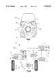
- FIG. 1is a schematic block diagram of a system, made in accordance with the present invention, for establishing current control values for an electric motor;
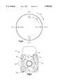
- FIG. 2is a cross-sectional view of a variable reluctance motor
- FIG. 3is a schematic block diagram of an electric power assist steering system which includes the variable reluctance motor of FIG. 2;
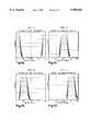
- FIGS. 4A-4Dare graphical representations of current control values stored in a look-up table for incremental torque values for the four motor phases;
- FIG. 5is a graphical depiction of the selection process of look-up tables as a function of electrical angle and the motor operating quadrant;
- FIG. 6is a cross-sectional view of a variable reluctance motor similar to FIG. 2 showing the magnetic polarity of each of the motor phase coils during stator energization;
- FIG. 7is a graph diagram showing the effect that gain balancing the torque ripple estimate has on motor torque ripple.
- FIG. 8is a flow chart of the control process of the present invention.
- a test stand arrangement 20is shown that, in accordance with the present invention, is used to establish motor current control values for an electric motor 22.
- the present inventionis applicable to any electric motor of the type that is controlled in response to sensed rotor position, it is described herein for use with a variable reluctance motor. The invention is not limited in its use to variable reluctance motors.
- variable reluctance motor 22is described herein is an eight stator pole/four rotor pole, four phase motor with the specific purpose of providing power assist in a rack and pinion steering system.
- the present inventionis equally applicable to other motor configurations and other motor purposes such as machine tools.
- torque ripple exhibited by the electric assist motor during operationcan be felt by the vehicle operator through the steering wheel. Therefore, it is desirable to minimize torque ripple in a steering system using an electric assist motor.
- the motor 22includes a rotor 24 and a stator 26.
- the stator 26is secured to a motor housing 27.
- the rotor 24is connected a motor connection tube 28.
- the rotor 24has six rotor poles 30, and the stator 26 has eight stator poles 32.
- the motor 22is a four phase motor.
- the four phasesare designated Phase A, Phase B, Phase C, and Phase D.
- Phases A, B, C, and Dcorrespond to stator poles Aa, Bb, Cc, and Dd, respectively.
- the stator polescarry associated coils (not shown) in a manner well known in the art.
- the motor 22is described as a four phase variable reluctance motor merely for the sake of clarity and ease of description.
- the present inventionis not limited to this particular motor type, nor arrangement, and can be used with any electric motor that is controlled in response to sensed rotor position.
- variable reluctance motorThe operation of a variable reluctance motor is known in the art and is not described herein in detail.
- U.S. Pat. No. 4,670,696 to Byrne et al.describes the construction and operation of a typical variable reluctance motor and is hereby fully incorporated herein by reference.
- an electric power assist steering system 38includes a steering wheel 40 connected to an input shaft 42.
- the input shaft 42is connected through a torsion bar 44 to an output shaft 46.
- a position sensor 48is connected to the input shaft 42 and to the output shaft 46.
- the position sensor 48determines the relative rotational position between the input shaft 42 and the output shaft 46. Because of the torsion bar 44, this relative rotational position between the input shaft 42 and the output shaft 46 is indicative of the amount of steering torque applied to the steering wheel 40.
- the combination of the position sensor 48 and the torsion bar 44function together as a torque sensor 50.
- the torque sensor 50provides an applied steering torque signal 52 having a value indicative of the amount of steering torque applied to the steering wheel 40.
- the output shaft 46is connected to a pinion gear of a rack and pinon gear set 54.
- the rack and pinon gear set 54functions to transform the rotational motion of the steering wheel 40 into linear motion of a steering rack 56.
- the steering rack 56is steerably connected to steerable wheels 58, 60 of the vehicle in a manner well known in the art.
- the linear movement of the steering rack 56steers the steerable wheels 58, 60 of the vehicle.
- the connection tube 28 of the variable reluctance motor 22is drivably connected to the rack 56 through a ball-nut assembly in a manner known in the art.
- One such ball-nut drive arrangement between an electric assist motor and a rack memberis shown in U.S. Pat. No. 4,666,014 to Carlson et al. and is hereby fully incorporated herein by reference.
- a motor rotor position sensor 62is operatively coupled to the motor 22 and senses the position of the rotor 24 relative to the stator 26 and provides a rotor position signal 64 having a value indicating that relative position therebetween.
- the structure and operation of a rotor position sensor for use with a variable reluctance motoris known in the art and is, therefore, not described herein in detail.
- a preferred rotor position sensor for use with the present inventionis disclosed in U.S. patent application Ser. No. 08/329,206, filed Oct. 10, 1994, to Persson et al., entitled “Method and Apparatus for Sensing Relative Position Between Two Relatively Rotatable Members Using Concentric Rings", and is hereby fully incorporated herein by reference.
- the rotor position sensor 62measures the rotor electrical angle as opposed to the rotor's mechanical angle relative to the stator.
- a mechanical cycle of 360 mechanical degreesoccurs when the rotor is rotated one complete revolution.
- An electrical cycle of 360 electrical degreesoccurs when the motor is rotated through 60 mechanical degrees. Therefore, there are 6 electrical cycles for every 1 mechanical cycle for the preferred 8/6 variable reluctance motor arrangement described herein.
- zero electrical degreesis defined as the rotor position which occurs when Phase D is locked with sufficient current to overcome friction effects. Note that there are six possible rotor mechanical locations where energizing Phase D will lock the rotor, i.e., the rotor location when a rotor tooth is fully aligned with the stator teeth Dd.
- a controller 66such as a microcomputer, monitors the rotor position signal 64 and the applied steering torque signal 52 and, in response thereto, controls the energization of the motor 22 through power switches 68.
- a preferred drive arrangement for the power switches 68is fully described in U.S. patent application Ser. No. 08/334,231, filed Nov. 4, 1994, to Beck entitled “Method and Apparatus for Controlling an Electric Assist Motor", which is hereby fully incorporated herein by reference.
- the controller 66is preferably a microcomputer having an internal ROM memory used as a look-up table 67. Also, the look-up table could be stored in a flash RAM. Stored in this look-up table 67 are motor current control values used for control of the motor 22. The motor current control values are stored in the look-up table 67 as a function of the desired steering assist torque and sensed rotor position.
- the controller 66selects a motor current value from the table as a function of the applied steering torque signal 52 and sensed rotor position.
- the motor current valueis that value of current that must be applied to the motor 22 so that the motor provides a desired amount of steering assist torque.
- Other variables, e.g., vehicle speed,could be considered in selection of the motor current value needed to achieve the desired steering assist.
- An arrangement that includes a steering system that looks up a motor control value in a look-up tableis fully described in U.S. Pat. No. 5,475,289 to McLaughlin et al. entitled "Method and Apparatus for Controlling an Electric Assist Steering System Using Two-Dimensional Interpolation for Current Commands", which is hereby fully incorporated herein by reference.
- the motor current control values used to control the electric assist motor 22are stored in a plurality of look-up tables (i.e., the look-up table 67 is partitioned to form a plurality of separate look-up tables).
- the memory deviceis partitioned to form ten look-up tables.
- the maximum expected value of steering assist torqueis divided by ten to define ten incremental levels of steering assist torque.
- Sets of current control values corresponding to each of the ten incremental values of steering assist torqueare stored in associated look-up tables.
- table number onehas current control values as a function of rotor position for a steering torque assist value equal to 10% of the maximum steering assist torque value
- table twohas current control values as a function of rotor position for a steering torque assist value equal to 20% of the maximum expected steering assist torque value, etc.
- Torque rippleis a torque variation in the motor's output that occurs when a constant torque is commanded from the motor.
- the phenomenon of torque rippleis well known in the art of variable reluctance motors.
- torque rippleis particularly undesirable because it can be felt by the vehicle operator through the steering wheel.
- torque ripple that would typically occur in the operation of the variable reluctance motoris substantially reduced by establishing current control values in the look-up table 67 through a process of anticausally filtering torque ripple estimates.
- the motor operationis monitored under load conditions.
- the test stand arrangement 20is a dynamometer used to establish current control values that will be stored in the look-up tables 67 to provide substantially reduced ripple in the electric assist steering system 38.
- the test stand 20operates the motor 22 under load conditions.
- a load 34is connected to the motor output tube 28.
- the load 34provides a constant load on the motor 22 when the motor is energized.
- a torque sensor 36is operatively connected to the motor output tube 28 and provides a signal having a value which indicates the output torque ⁇ meas of the motor 22, i.e., the motor's measured output torque.
- a controller 65is connected to an input device 71.
- the input device 71is preferably a keyboard or other known input device.
- the input device 71is used to input a desired torque request to the controller 65. This torque request is the desired torque to be developed by the motor 22.
- a torque request ⁇ req value 69is output from controller 65 to one input of a summing circuit 70.
- the summing circuit 70sums the value of the torque request ⁇ req with a filtered torque ripple estimate vector ⁇ ftre (described below) provided by a torque ripple controller 72.
- the torque ripple estimate vector ⁇ ftreis also referred to herein as the feed-forward torque signal.
- the summing circuit 70outputs a torque command signal ⁇ cmd which is equal to the sum of the torque request value ⁇ req from controller 67 and the filtered torque ripple estimate vector ⁇ ftre from the torque ripple controller 72.
- the torque command signal ⁇ cmdis output from the summing circuit 70 to an interpolation circuit 74.
- a rotor position sensor 73is operatively connected to the motor 22 and provides a rotor position signal 75 having a value indicative of the relative rotational position between the motor rotor 24 and the motor stator 26.
- the electrical anglerefers to electrical cycle angles and mechanical angle refers to absolute rotor position. Calculations performed in accordance with the present invention are done in terms of the electrical angle. One skilled in the art will appreciate that calculations could be done in terms of the mechanical angle. By doing computations in terms of electrical cycles, there is an assumption that all electrical cycles produce torque that is identical. Although this assumption is not completely accurate, it does provide good results.
- the rotor position sensor 73is a resolver that outputs 14 bits (or 21 4 counts) of data equivalent to 360 mechanical degrees of rotation.
- there are 6 electrical degrees per mechanical degreebecause an electrical cycle is only 60 mechanical degrees or 1/6 th of a mechanical cycle. Assuming that zero mechanical degrees corresponds to one of the six possible rotor angles for zero electrical degrees, the measure of mechanical angle is easily converted to electrical angle for the present 8/6 motor as:
- 70is the integer function that truncates the result of the divide to the next lowest integer.
- the function ⁇ ( ⁇ mechanical /6)computes the number of electrical cycles. Multiplying this result by 60 and subtracting it from the measured mechanical angle provides a measure of how many mechanical degrees the rotor is within the present electrical cycle. This result is then multiplied by 6 to convert it to an electrical angle.
- the rotor position signal 75is output to the interpolation circuit 74.
- the interpolation circuit 74monitors the torque command signal ⁇ cmd (which is the sum of ⁇ req and ⁇ ftre ) and the rotor position signal and, in response thereto, outputs four motor current commands I cmd signals, i.e., one for each of the four motor phases.
- the interpolation circuit 74utilizes four sets of prestored, predetermined current profile tables 76, one set of tables for each of the four phases of the motor.
- the current profile tablesare stored in an internal memory 76 of the interpolation circuit 74.
- Each of the sets of current profile tableshas a plurality of 1 ⁇ n arrays of stored current values, each array associated with a particular torque command value ⁇ cmd .
- the current value within the arrayis selected in response to a sensed motor rotor position.
- the number of current values n stored in each of the arraysis related to the electrical angular resolution of the rotor position sensor 73. In accordance with a preferred embodiment, n equals 200. Therefore, each of the current profile tables for a motor phase has 200 current values for an associated torque command value ⁇ cmd .
- Each set of stored current control profile tables for the four phasesis associated with a 10% increment of, the maximum allowable torque value from the motor 22.
- initial current profile tables 76may be calculated for the particular motor 22 being controlled. Such calculated initial tables 76 would be based upon a theoretical model of the motor 22, i.e., tables having current values required to cause the theoretical motor to develop the desired output torque. Alternatively, the motor manufacturer can provide initial current profile tables 76 for the particular motor being used. Also, current profile tables 76 may be generated based upon an average of a plurality of motors of the particular motor model of concern. The only limitation on the initial values stored in the current profile tables 76 is that the stored values must generate the average output torque at each associated 10% torque level.
- Torque ripplecan occur if the motor was controlled using those initial stored values 76 in the tables 67.
- the values in the torque table 76must produce close to the associated average or DC torque level, i.e., ⁇ 10%. They do not have to produce the exact average.
- One set of current profile tables(10 sets of tables, each table having a set of current control values for an associated 10% torque increment value) is stored in 76. Although each increment of torque has tables for each of the four phases, each set of tables is used independent of the motor operating direction.
- An electric motorhas, what is referred to in the art, as four quadrants of operation. If the motor is being commanded to turn clockwise (positive) and is, in fact, turning clockwise (positive), the motor is said to operating in quadrant I. If the motor is being command to turn counterclockwise (negative) and is, in fact, turning counterclockwise (negative), the motor is said to be operating in quadrant III.
- Each of the sets of ten current profile tablesis, itself, partitioned into four tables, i.e., each phase, for a particular torque level, has its own associated torque table.
- each phasefor a particular torque level
- the current values for any particular phase relative to rotor positionwould not be the same for quadrant I (positive rotation with positive command) as it would be for quadrant III (negative rotation with negative command) operation.
- T 1 , T 2 , T 3 , and T 4The four torque tables for that torque level are referred to as T 1 , T 2 , T 3 , and T 4 . This nomenclature is used to distinguish between the four different profile tables and does not indicate a phase that is to be commanded with a selected one of the profile tables.
- the tableis put in parenthesis after the phase, e.g., A(T 1 ) indicates table T 1 is used to command phase A, C(T 2 ) indicates that table T 2 is used to command phase C, etc.
- FIGS. 4A-4DA typical set of profile tables is shown in FIGS. 4A-4D.
- the x-axisis the electrical angle that is used to index into the tables and the y-axis is the motor command current in amps.
- each of the 10% current profile tablesare depicted as continuous curves, each 10% table has 200 finite stored current control values, one for each 1/200 th of an electrical angle. Therefore, large portions of each table contains zeros.
- table T 2FIG. 4B, is non-zero only for motor angles ⁇ where 20 ⁇ 95. The non-zero values are discrete points that are the bases for the continuous curves depicted.
- the large circlerepresents electrical angle. Once around the circle is a single electrical cycle, i.e., 360 electrical degrees or 60 mechanical degrees.
- the clockwise directionis for increasing angle or positive rotor direction and the counter-clockwise direction is for decreasing angle or negative rotor direction.
- This sequencecorresponds to the motor operating in the quadrant III since the motor rotor direction and the torque are both negative, i.e., the motor is commanded to move counterclockwise and is, in fact, moving counterclockwise. Both of these sequences are indicated in FIG. 5 by moving around the circle in either a clockwise (quadrant I or Q 1 ) direction or a counterclockwise direction (quadrant III or Q 3 ) direction.
- phase energizing sequence for quadrants I and III operationis defined by the construction of the motor.
- the tables used to command the transition between phases A and Dmust be the same in both quadrants I and III.
- the four current profile tablesmust be passed through in the same order whether in quadrants I or III.
- phase AAt any given angle, opposite polarity torques are achieved by energizing phases that are 180 electrical degrees apart. At 0 electrical degrees, phase A generates positive torque and phase C generates negative torque. At 100 electrical degrees, phase C generates positive torque and phase A negative torque. If the phases are energized in the sequence ABCD, the motor will rotate in the positive direction. If the phases are energized in the sequence CBAD, the motor will rotate in the negative direction. Therefore, the location of the phases with respect to the angles on the inside and outside of the circle, i.e., the required angles and sequence for quadrants I and III, are dictated purely by the motor construction.
- the VR motor current to torque gainis different in the D to A transition than in all other transitions because magnetic field structure is different in the region.
- FIG. 6the magnetic polarity of each of the motor phase coils are shown.
- the magneticsare such that very little flux sums in the back iron as the flux lines flow from North to South.
- the AD transitionthe flux lines flow in the same direction in the back iron thereby increasing saturation and reducing the amount of incremental torque for an incremental current change.
- the current commands in tables T 1 and T 4 within the D to A transitionare different than the other three transitions.
- the four current profile tablesmust be passed through in the same order whether in quadrants I or III.
- the definition of the quadrants I and IIIare arbitrary to the external observer. If a given table commanding sequence is used in quadrant I, a transformation can be performed to the measured motor angle to allow the same table commanding sequence to be used in quadrant III.
- the motor angle Omeasis used to directly look up the current command, the motor rotor direction is positive, and ⁇ meas is increasing positively.
- the transformed motor angle ⁇ Q3is used to look up the current commands, the motor rotor direction is negative, yet ⁇ Q3 is also increasing positively. Therefore, applying this transformation satisfies the above constraint of passing through the tables in the same order because the indices in the tables ⁇ meas and ⁇ Q3 are both increasing in quadrants I and III, respectively. Not only does this transformation allow the tables to be indexed through in the same order, whether in quadrants I or III, it also satisfies the constraint of keeping tables T 1 and T 4 in the A to D transition.
- ⁇ Q3-25 deg. or 175 deg.
- ⁇ Q1 ( ⁇ ) and ⁇ Q3 (50- ⁇ )are the torques produced at angle for the current as specified in the tables.
- ⁇ torques in these equationsare nonlinear functions of three variables: the motor angle, the current in phase A, and the current in phase D. If these equations are linerized about the operating points ⁇ , T 1 ( ⁇ ), T 4 ( ⁇ ), and the partial derivative of the torque with respect to the angle ⁇ is neglected by assuming that position information is perfect, the incremental torques are:
- K D and K Aare the partial derivatives of the torque with respect to the currents evaluated at [ ⁇ , T 1 ( ⁇ ), T 4 ( ⁇ )], and ⁇ T 1 , ⁇ T 4 are the perturbations in current from the defined profile tables.
- the reason the gains K A and K D are referenced to (50- ⁇ ) rather than ( ⁇ ) in the one equation aboveis that the gains must be calculated at the physical rotor position while the tables are always referenced to a Q 1 angle. Since the rotor is at (50- ⁇ ) where ⁇ is a Q 1 angle, the partial derivative of the torque with respect to current must be evaluated at the rotor angle (50- ⁇ ), and the delta currents ⁇ T must be referenced to the pretransformed Q 1 angle ⁇ . Substituting the results into the motor torque production equation above yields:
- the interpolation circuit 74determines the position of the rotor 24 from the position sensor signal 75 output from position sensor 73 and monitors the torque command signal ⁇ cmd , Since the current profile tables can only store a finite number of values, the actual current control value that is to be output from the circuit 74 is interpolated. Preferably, the interpolation is accomplished as is fully described in the above-incorporated U.S. Pat. No. 5,475,289 to McLaughlin et al.
- the current command I cmdis interpolated between the two current values.
- the current command I cmd for the Phases A, B, C, and Dare referred herein as I acmd , I bcmd , I ccmd , and I dsmd , respectively.
- the current commands determined by the interpolation circuit 74are output to a gain controller 78.
- the filtered torque ripple estimator vector value ⁇ ftreis connected to a gain controller 78.
- the gain controller 78multiplies the current command value output from the interpolation circuit 74 for a particular motor phase by a gain multiplier value associated with that motor phase to yield a final motor current control value for each phase.
- the gain multipliers for Phases A, B. C, and Dare referred to herein as G a , G b , G c , and G d , respectively.
- the current control values for Phases A, B, C, and Dare given by the products G a I acmd , G b I bcmd , G c I ccmd , and G d I dcmd , respectively.
- the values for the gain multipliersare determined by the gain controller 78 in response to the total filtered torque ripple estimate vector ⁇ ftre . Initially, each of the four gain multipliers is set equal to one.
- the current control values output from the gain controller 78are used as command signals for a closed loop current controller 79.
- the closed loop current controlleruses both the sensed current in the motor 22 and the current control values output from the gain controller 78 for control of the motor current in a closed loop fashion for each motor phase using pulse-width-modulation ("PWM").
- PWMpulse-width-modulation
- the PWM signalscontrol applied current to the motor 22 which, in turn, controls the output torque developed by the motor 22.
- the torque ripple controller 72monitors the torque request value 69, the motor rotor position signal 75, and measured motor torque ⁇ meas and, in response thereto, determines a filtered torque ripple estimate vector ⁇ ftre having 200 component points.
- Each component value of the vector ⁇ ftreis designated ⁇ ftre (i), where i is an index value which corresponds to an associated rotor electrical angle.
- the filtered torque ripple estimate valueis also referred to as the feed-forward torque value.
- the index value ivaries from 1 to 200, which means there are 200 estimates of feed-forward torque ⁇ ftre (i) for one electrical cycle of the rotor 24.
- each feed-forward component ⁇ ftre (i)is the average of the measured torque ripple over the angular interval i+0.5> ⁇ >i-0.5, where ⁇ is the measured electrical angle.
- a torque ripple estimatethat is a function of the motor electrical angle ⁇ ftre ( ⁇ ) is computed. This vector value is added to the desired torque request ⁇ req to arrive at the torque command value ⁇ cmd .
- the torque command value ⁇ cmdis varied with electrical angle such that the measured torque ⁇ meas from the motor is identically equal to the requested torque ⁇ req at all electrical angles.
- the filtered torque ripple estimate value ⁇ ftreis computed using the following process:
- Spatial frequencyhas units of cycles per electrical cycles. Spatial frequencies also corresponds directly to motor control phenomena. For example, there are four phases in the preferred motor arrangement. Therefore, there are four commutation regions within each electrical cycle, i.e., each one of the four phases is turned ON during an electrical cycle.
- ⁇ ttime domain frequency (Hz)
- ⁇ mmotor rotor speed (rpm).
- an 8/6 motorhas 24 commutations per revolution. If the motor is rotated at 1 revolution per second, the commutation frequency will be at 24 Hz, i.e., 24 commutations per second.
- the commutation frequencywill be at 24 Hz, i.e., 24 commutations per second.
- Application of this ripple reduction algorithmwill effectively eliminate torque ripple below 16 cycles/electrical cycles and 32 Hz.
- the source code to accomplish the anticausal filtering of the torqueis attached as subroutine anti -- filt in Appendix A.
- a standard causal filterinherently introduces increasing phase lag as the slope of the filter's gain reduction is increased.
- the gain and phaseare decoupled in the anticausal filter 83. This arrangement provides attenuation via the filter gain without introducing any phase lag.
- the anticausal filter 83derives its name from the fact that time is "reversed” to achieve filtering without a phase lag with respect to the original measured torque ⁇ meas .
- the spatial filterrecovers the phase lag induced by the time domain filter. Since time cannot literally be "reversed” in a causal filter, the name anticausal is used to describe this type of filter.
- the anticausal filter 83is preferably implemented in software in the torque ripple controller 72 using the source code set forth in Appendix A.
- the torque ripple controller 72is a microcomputer.
- the Z-domain cutoff frequency of the spatial filtermust be defined.
- the pole of the filteris specified as a spatial frequency in units of cycles per electrical cycles. That is, the operator specifies the spatial frequency above which no energy passes in units of cycles per electrical cycles. Spatial frequencies, as opposed to time domain frequencies, are convenient to use with variable reluctance motors because they do not change with motor rotor direction.
- Appendix Ais a software program listing showing a software implementation of the anticausal filter 83 in accordance with a preferred embodiment of the present invention.
- the program listingis but one way of accomplishing the anticausal filtering process of the present invention and should not be viewed as a limitation of the present invention.
- the pole of the filteris set to 16 cycles per electrical cycles.
- the anticausal filteris discrete, therefore, the pole is mapped to the Z-domain. Since there are 200 points in the vector ⁇ ftre which are to be filtered and the vector has an angular length of one electrical cycle, this is equivalent to 200 samples/electrical cycle. If s is the spatial frequency in units of cycles per electrical cycles (16 for this preferred embodiment) and T is the sample rate in units of electrical cycles (1/200 for this preferred embodiment), then the Z-domain pole is computed as
- the ripple controller 72adds the output ⁇ filt (i) of the anticausal filter 83 to a filtered torque ripple estimate vector ⁇ ftre .
- the total torque ripple estimate vector ⁇ ftreis given by the equation:
- Kis a gain value between 0 and 1.
- the effect of the gain Kis that only a percentage of the output ⁇ filt (i) is added to the existing total torque ripple estimate vector ⁇ ftre . Adding only a percentage of output ⁇ filt (i) allows for slow convergence of the vector ⁇ ftre in case non-linear effects become dominant. All 200 components of the vector ⁇ ftre are zero the first time through the algorithm.
- K0.9 for torque levels greater than 10% and is equal to 0.5 for torque levels less than 10%.
- the filtered torque ripple estimate vector ⁇ ftreis provided to the summing circuit 70.
- the first time through the determination processall components of the vector ⁇ ftre equal zero so the torque command ⁇ cmd equals the torque request ⁇ req .
- the torque command ⁇ cmdequals the torque request ⁇ req .
- ⁇is the position of the rotor 24.
- Each component of the vector ⁇ ftreis termed a feed-forward ripple estimate because for a rotor position ⁇ such that i+0.5 ⁇ >i-0.5, the component ⁇ ftre is summed to the torque request ⁇ req .
- the component ⁇ ftre (i)is used to adjust the torque request ⁇ req over the angular interval i+0.5 ⁇ >i-0.5.
- the torque ripple controller 72updates the total torque ripple estimate vector ⁇ ftre (i) until the controller 72 determines the vector is "acceptable.”
- An acceptable vectoroccurs when the ripple of the motor 22 is less than a predetermined threshold. For a variable reluctance motor to be used in an electric steering system, this torque ripple threshold is less than or equal to 1 in-lb.
- the peak-to-peak torque rippleis defined by the maximum minus the minimum torque measured by the torque sensor 36 over one mechanical revolution of the rotor 24.
- the ripple controller 72that determines the peak-to-peak torque ripple is acceptable, it communicates this fact via an evaluation signal 84 to the gain controller 78.
- the evaluation signal 84has a digital "HIGH” value when the controller 72 has determined the peak-to-peak torque ripple is acceptable, and a digital "LOW” otherwise.
- the gain controller 78receives a digital HIGH evaluation signal 84, it performs gain balancing of the filtered torque ripple estimate vector ⁇ ftre . Gain balancing ensures that the estimate vector ⁇ ftre is at the same level for all four motor phases when only one motor phase is energized.
- FIG. 7shows that when the filtered ripple estimate vector ⁇ ftre is gain balanced, the same levels of torque ripple occur when only a single phase is energized.
- the X-axisrepresents the electrical angle and the Y-axis represents the component values of the total torque ripple estimate vector ⁇ ftre .
- the current profile tablesare defined such that for electrical angles from 1 to 20, only Phase A is energized. For electrical angles from 51 to 70, only Phase B is energized. Similarly, Phase C only is energized for electrical angles from 101 to 120 and Phase D only is energized for electrical angles from 151 to 170.
- the gain controller 78performs gain balancing by determining a gain multiplier for each motor phase. To determine the gain multipliers, the controller 78 first calculates a local gain for each phase.
- the local gain of each phaseis defined as the average torque ripple over the interval of angles when only that phase is energized.
- the equations evaluated by the controller 78 to calculate the local gainsare:
- the controller 78next determines a gain balance term for the Phases A, B, C, and D in accordance with the following equations:
- the gain balance terms for the Phases B, C, and Dare normalized to the local gain of Phase A. Each gain balance term may be thought of as a percentage error with respect to the torque command ⁇ cmd . Finally, the controller 78 determines the gain multiplier for each phase in accordance with the following equations:
- the controller 78then utilizes these multipliers to adjust the current commands provided by the interpolation circuit 74.
- the gain multiplier values and the torque ripple estimate vectorsare then stored for a particular motor 22 under calibration in the look-up tables 67 of the electric assist steering controller 66 that will be associated with that motor.
- gain balancingis only required if the table computed for quadrant I is to be also used for quadrant III. If the tables are not to be shared, i.e., each quadrant has its own set of tables for the four phases, gain balancing is not required.
- step 102the motor 22 is commanded with a constant torque request value ⁇ req .
- step 104current is provided to the motor 22 to cause the motor to develop the torque request ⁇ req at a constant rotor speed.
- step 106current is provided to the motor 22 to cause the motor to develop the torque request ⁇ req at a constant rotor speed.
- step 106the measured torque ripple is filtered in the time domain.
- step 108the filtered torque is averaged over all electrical angles. From step 108, the process goes to step 110.
- step 110the process anticausally filters the averaged torque ripple in the spatial domain.
- the anticausal filterrecovers the phase lag incurred by the time domain filtering performed in step 106. Thereafter, the process goes to step 112.
- step 112the anticausally filtered torque ripple is added to the filtered torque ripple vector ⁇ ftre .
- the averaged time domain filtered torque ripple determined during that cycleis used to update the anticausally filtered torque ripple estimate vector ⁇ ftre .
- step 112goes from step 112 to step 114, wherein the filtered torque ripple estimate vector ⁇ ftre is used in commanding the motor.
- the component ⁇ ftre (i) corresponding to that rotor positionis summed with the torque request ⁇ req to yield the torque command ⁇ cmd .
- the torque command ⁇ cmdis provided to the interpolation circuit 74, which determines the current to be supplied to the motor 22 from that torque command.
- the processthen goes to step 116.
- step 116the process determines whether the torque ripple of the motor 22 is acceptable. As previously described, the torque ripple is acceptable when the ripple is less than a predetermined threshold. If the torque ripple is not acceptable, the process goes back to step 106. The process executes steps 106 through 116 until the vector ⁇ ftre is acceptable. Once the inquiry in step 116 is affirmative, the process goes to step 118.
- step 118the vector ⁇ ftre is gain balanced (if needed) to assure the same amount of torque ripple is present when any of the phases A, B, C, or D is solely energized. From step 118, the process proceeds to step 120 where it is once again determined whether the torque ripple is acceptable. If the determination in step 120 is negative, the process goes back to step 106. The process executes steps 106 through 120 until the gain balanced vector ⁇ ftre is such that the torque ripple is acceptable. Once step 120 determines the torque ripple is acceptable, the process is complete and it goes to step 122 and ends.
- Quadrant IIpositive motor torque, negative motor rotation.
- Quadrant III(Q 3 ): negative motor torque, negative motor rotation.
- Quadrant IV(Q 4 ): negative motor torque, positive motor rotation.
- the feed-forward torque vectors ⁇ ftre and the gain balance termsare stored.
- the current profile tables for storage in the look-up tables 67 of controller 68 for each of the motor quadrantsare determined as follows:
- step (3)If the requested torque commanded is less 100%, return to step (3).
- the gain balance terms for a single phaseare nearly equal at all torque levels.
- the gain balance terms for the 50% torque levelare used for all other torque levels.
- the gain balance termis selected for the torque level where the motor is mainly used. For example, if the motor is mainly drive at a 60% torque level, the gain balance terms for the 60% level would be used for all the other torque levels.
- gain balancing termsare not required since tables generated for each of the four quadrants, in accordance with the present invention, will be substantially ripple free.
- the above described systemhas computed the feed-forward torque ⁇ ftre for electrical cycles with the assumption that all electrical cycles produce torque identically the same. Although this is a good assumption, there can be some variance in the actual torque produced during the electrical cycles. For example, if the motor exhibits a 1-2 in-lb torque variation between electrical cycles, this torque ripple will still be present even after using the above-described ripple reduction process. If, however, the feed-forward torque is determined in accordance with the mechanical motor angle, the motor output torque ripple can be made equal to the noise floor of the system within a specified frequency range.
- the average (time domain) and anticausally (spatial domain) filtered torque vectoris computed based on mechanical revolution rather than electrical revolution. In this way, it is no longer necessary to assume that each electrical cycle produces torque in the same fashion.
- torque ripplecan be reduced to less than 0.5% peak-to-peak of full motor output torque.
Landscapes
- Engineering & Computer Science (AREA)
- Power Engineering (AREA)
- Control Of Electric Motors In General (AREA)
- Power Steering Mechanism (AREA)
- Control Of Motors That Do Not Use Commutators (AREA)
Abstract
Description
θ.sub.electrical =6×(θ.sub.mechanical -ζ(θ.sub.mechanical /6)×60)
τ.sub.Q3 (50-θ)=τ[A(T.sub.4 (θ))+D(T.sub.1 (θ))]
τ.sub.Q1 (θ)=τ[D(T.sub.4 (θ))+A(T.sub.1 (θ))]
δτ.sub.Q1 (θ)=K.sub.D (θ)×δT.sub.4 (θ)+K.sub.A (θ)×δT.sub.1 (θ)
δτ.sub.Q3 (50-θ)=[K.sub.A (50-θ)×δT.sub.4 (θ)+K.sub.D (50-θ)×δT.sub.1 (θ)]
K.sub.D (θ)×δT.sub.4 (θ)+K.sub.A (θ)×δT.sub.1 (θ)=-[K.sub.A (50-θ)×δT.sub.4 (θ)+K.sub.D (50-θ)×δT.sub.1 (θ)
[(K.sub.D (θ)+K.sub.A (50-θ)]×δT.sub.4 (θ)+[K.sub.A (θ)+K.sub.D (50-θ)]×δT.sub.1 (θ)=0
K.sub.D (θ)+K.sub.A (50-θ)=0
K.sub.A (θ)+K.sub.D (50-θ)=0
τ.sub.Q1 (θ)=-τ.sub.Q3 (50 -θ)
z=e.sup.-2πsT
τ.sub.ftre (i)=τ.sub.ftre (i)+K*τ.sub.filt (i), for i=1,200
.sub.cmd =τ.sub.req +τ.sub.ftre (i) for i+0.5≦θ>i-0.5
______________________________________ G.sub.aloc = Σ(τ.sub.ftre (i) - mean(τ.sub.ftre))/20 for i = 1, 20 Phase A G.sub.bloc = Σ(τ.sub.ftre (i) - mean(τ.sub.ftre))/20 for i = 51, 70 Phase B G.sub.cloc = Σ(τ.sub.ftre (i) - mean(τ.sub.ftre))/20 for i = 101, 120 Phase C G.sub.dloc = Σ(τ.sub.ftre (i) - mean(τ.sub.ftre))/20 for i = 151, 170 Phase D ______________________________________
______________________________________ G.sub.abal = 1 Phase A G.sub.bbal = 1 - (G.sub.Aloc - G.sub.Bloc)/τ.sub.cmd Phase B G.sub.cbal = 1 - (G.sub.Aloc - G.sub.Cloc)/τ.sub.cmd Phase C G.sub.dbal = 1 - (G.sub.Aloc - G.sub.Dloc)/τ.sub.cmd Phase D ______________________________________
G.sub.amult =G.sub.abal =1
G.sub.bmult =G.sub.bmult *G.sub.Bbal
G.sub.cmult =G.sub.cmult *G.sub.Cbal
G.sub.dmult =G.sub.dmult *G.sub.Dbal
APPENDIX A __________________________________________________________________________void butter.sub.-- filt0 /*========================================================================This routine implements an Nth order butterworth filter. The s-domain poles are mapped to the z-domain using Tustin's rule. The inputs and outputs are: inputs: butter.sub.-- first Input flag used to initialize the filter. Set =1 to initialize the filter and/or to compute new filter coefficients due to the break frequency of the filter changing. anti.sub.-- pole The spatial break frequency for the filter. Generally, anti.sub.-- pole is set to 16 cycles per electrical cycle. motor.sub.-- rpm The motor rotational rate in units of rpm. torque.sub.-- meas The measured motor torque. outputs: torque.sub.-- meas.sub.-- filt The filtered motor torque. ========================================================================*/float tmp1, tmp2, tmp3, tmp4, alpha; float zeta[5]; float freq[5]; long i.sub.-- butter, j.sub.-- butter, kkk; /* Calculate all coefficients if butter.sub.-- first=] */ if(butter.sub.-- first=1) { butter.sub.-- first=0; butter.sub.-- wn=fabs(anti.sub.-- pole/(10.0/rpm.sub.-- setpnt)); .sup. butter.sub.-- first = 1; for(j.sub.-- butter=0; j.sub.-- butter<6; j.sub.-- butter++) {/*Modified the initialization to set past filter states to the filtered torque. butter.sub.-- yn[j.sub.-- butter]=0.0; butter.sub.-- ynmin1[j.sub.-- butter]=0.0; butter.sub.-- ynmin2[j.sub.-- butter]=0.0; */ butter.sub.-- yn[j.sub.-- butter]=torque.sub.-- meas.sub.-- filt; butter.sub.-- ynmin1[j.sub.-- butter]=torque.sub.-- meas.sub.-- filt; butter.sub.-- ynmin2[j.sub.-- butter]=torque.sub.-- meas.sub.-- filt; } butter.sub.-- npoles=3; zeta[0]=sin(45.0*PI/180.0); freq[0]=butter.sub.-- wn*2.0*PI; zeta[1]=sin(75.0*pi/180.0); freq[1]=butter.sub.-- wn*2.0*PI; zeta[2]=sin(15.0*PI/180.0); freq[2]=butter.sub.-- wn*2.0*PI; /* Compute the coefficients for the filter. The filters are set up as 3 separate bi-quads* for(i.sub.-- butter=1; i.sub.-- butter<butter.sub.-- npoles+1; i.sub.-- butter++) { tmp1=(freq[i.sub.-- butter-1]*cycle.sub.-- time)*(freq[i.sub.-- butter-1]*cycle.sub.-- time); tmp2=4.0*(1.0+zeta[i.sub.-- butter-1]*freq[i.sub.-- butter-1]*cycle.sub.-- time)+tmp1; tmp3=2.0*tmp1-8.0; tmp4=4.0*(1.0zeta[i.sub.-- butter-1]*freq[i.sub.-- butter-1]*cycle.sub.-- time)+tmp1; butter.sub.-- a[i.sub.-- butter]=tmp1/tmp2; butter.sub.-- b[i.sub.-- butter]=tmp3/tmp2; butter.sub.-- c[i.sub.-- butter]=tmp4/tmp2; } flag+=0; } /*Assign butter.sub.-- yn the input measured torque. */ .sup. butter.sub.-- yn[0]=torque.sub.-- meas; .sup. for(j.sub.-- butter=1; j.sub.-- butter<butter.sub.-- npoles+1; j.sub.-- butter++) .sup. { butter.sub.-- yn[j.sub.-- butter]=butter.sub.-- b[j.sub.-- butter]*butter.sub.-- ynmin1[j.sub.-- butter]+ butter.sub.-- c[j.sub.-- butter]*butter.sub.-- ynmin2[j.sub.-- butter] +butter.sub.-- a[j.sub.-- butter]*(butter.sub.-- yn[j.sub.-- butter-1]+2.0*butter.sub.-- ynmin1 [j-butter-1]+butter.sub.-- ynmin2[j.sub.-- butter-1]); } for(j.sub.-- butter=0; j.sub.-- butter<butter.sub.-- npoles+1; j.sub.-- butter++) { butter.sub.-- ynmin2[j.sub.-- butter]=butter.sub.-- ynmin1[j.sub.-- butter]; butter.sub.-- ynmin1[j.sub.-- butter]=butter.sub.-- yn[j.sub.-- butter]; } /*Assign torque.sub.-- meas.sub.-- filt the filtered torque signal. */ .sup. torque.sub.-- meas.sub.-- filt=butter.sub.-- yn[butter.sub.-- npoles]; } void anti.sub.-- itae.sub.-- filt( ) /*.sub.---------------------------------------------------------------------------- .sup. This routine implements a 6th order Butterworth filter anti-causally. .sup. The input is the 200 point array trq.sub.-- ff. The output is the 200 point .sup. array trq.sub.-- ff after being anti-causally filtered. Input/output variable .sup. names are the same as was used in butter.sub.-- filt. /*.sup.---------------------------------------------------------------------------- { float tmp1, tmp2, tmp3, tmp4, anti.sub.-- cycle; long i.sub.-- anti, anti.sub.-- npoles, j.sub.-- anti; /*.sub.---------------------------------------------------------------------------- .sup. Calculate the coefficients for the filter. The 6th order filter .sup. is realized as 3 second order filters in series. The mapping .sup. to the z-domain is accomplished using Tustin's rule without any prewarping. */.sup.---------------------------------------------------------------------------- accel.sub.-- meas.sub.-- z=anti.sub.-- pole; if(anti.sub.-- pole.sub.-- last !=anti.sub.-- pole) { anti.sub.-- pole=anti.sub.-- pole*2.0*3.1415927; anti.sub.-- pole=(2.0/0.005)*(tan(anti.sub.-- pole*0.005/2.0)); anti.sub.-- pole=anti.sub.-- pole/2.0/3.1415927; anti.sub.-- pole.sub.-- last=anti.sub.-- pole; anti.sub.-- npoles=3; anti.sub.-- zeta[0]=sin(45.0*PI/180.0); anti.sub.-- wn[0]=anti.sub.-- pole*2.0*PI; anti.sub.-- zeta[1]=sin(75.0*PI/180.0); anti.sub.-- wn[1]=anti pole*2.0*PI; anti.sub.-- zeta[2]=sin(15.0*PI/180.0); anti.sub.-- wn[2]=anti.sub.-- pole*2.0*PI; anti.sub.-- cycle=0.005; for(i.sub.-- anti=1; i.sub.-- anti<anti.sub.-- poles+1; i.sub.-- anti++) { tmpl=(anti.sub.-- wn[i.sub.-- anti-1]*anti.sub.-- cycle)*(anti.sub.-- wn[i.sub.-- anti- 1]*anti.sub.-- cycle); tmp2=4.0*(1.0+anti.sub.-- zeta[i.sub.-- anti-1)*anti.sub.-- wn[i.sub.-- anti- 1]*anti.sub.-- cycle)+tmp1; tmp3=2.0*tmp1-8.0; tmp4=4.0*(1.0.sub.-- anti.sub.-- zeta[i.sub.-- anti-1]*anti.sub.-- wn[i.sub.-- anti- 1]*anti.sub.-- cycle)+tmp1; anti.sub.-- a[i.sub.-- anti]=tmp1/tmp2; anti.sub.-- b[i.sub.-- anti]=tmp3/tmp2; anti.sub.-- c[i.sub.-- anti]=tmp4/tmp2; } } for(j.sub.-- anti=0; j.sub.-- anti<=5; j.sub.-- anti++) { v1[2000+j.sub.-- anti]=0.0; v1[4000+j.sub.-- anti]=0.0; v1[6000+j.sub.-- anti]=0.0; } /*-------------------------------------------------------- .sup. Take the last 200 points of the output of the 3rd filter .sup. and store these back into v1(1:400). ------------------------------------------------------- */ if(mtr.sub.-- rate filt>0.0) {for(j.sub.-- anti=0; j.sub.-- anti<200; j.sub.-- anti++)v1[j.sub.-- anti]=trq.sub.-- ff[j.sub.-- anti]; for(j.sub.-- anti=0; j.sub.-- anti<200; j.sub.-- anti++)v1[j.sub.-- anti+200]=trq.sub.-- ff[j.sub.-- anti]; for(j.sub.-- anti=0; j.sub.-- anti<200; j.sub.-- anti++)v1[j.sub.-- anti+400]=trq-ff[j.sub.-- anti]; for(j.sub.-- anti=0; j.sub.-- anti<200; j.sub.-- anti++)v1[j.sub.-- anti+600]=trq-ff[j.sub.-- anti]; }else {for(j.sub.-- anti=0; j.sub.-- anti<200; j.sub.-- anti++)v1[j.sub.-- anti]=trq.sub.-- ff[199-j.sub.-- anti]; for(j.sub.-- anti=0; j.sub.-- anti<200; j.sub.-- anti++)v1[j.sub.-- anti+200]=trq.sub.-- ff[199j.sub.-- anti]; for(j.sub.-- anti=0; j.sub.-- anti<200; j.sub.-- anti++)v1[j.sub.-- anti+400]=trq.sub.-- ff[199-j.sub.-- anti]; for(j.sub.-- anti=0; j.sub.-- anti<200; j.sub.-- anti++)v1[j.sub.-- anti+600]=trq.sub.-- ff[199-j.sub.-- anti]; } for(j.sub.-- anti=0; j.sub.-- anti<5; j.sub.-- anti++) { v1[2794+j.sub.-- anti]=0.0; v1[4794+j.sub.-- anti]=0.0; v1[6794+j.sub.-- anti]=0.0; } /*-------------------------------------------------------- reverse time filter the data. ------------------------------------------------------- */ for(j.sub.-- anti=797; j.sub.-- anti>=0; j.sub.-- anti--) { v1[j.sub.-- anti+2000]=anti.sub.-- b[1]*v1[j.sub.-- anti+2000+1] +anti.sub.-- c[1]*v1[j.sub.-- anti+2000+2] +anti.sub.-- a[1]*(v1[j.sub.-- anti]+2.0*v1[j.sub.-- anti+1]+v1[j.sub.-- anti+2); v1[j.sub.-- anti+4000]=anti.sub.-- b[2]*v1[j.sub.-- anti+4000+1] +anti.sub.-- c[2]*v1[j.sub.-- anti+4000+2] +anti.sub.-- a[2]*(v1[j.sub.-- anti+2000]+2.0*v1[j.sub.-- anti+2000+1]+v1[j.sub.-- anti+2000+2); v1[j.sub.-- anti+6000]=anti.sub.-- b[3]*v1[j.sub.-- anti+6000+1] +anti.sub.-- c[3]*v1[j.sub.-- anti+6000+2] +anti.sub.-- a[3]*(v1[j.sub.-- anti+4000]+2.0*v1[j.sub.-- anti+4000+1]+v1[j.sub.-- anti+4000+2); } /*-------------------------------------------------------- .sup. The anti-casually filtered data is the last 200 points of .sup. the reverse time filtered data. ------------------------------------------------------- */ if(mtr.sub.-- rate.sub.-- filt>0.0) {for(j.sub.-- anti=0; j.sub.-- anti<200; j.sub.-- anti++)trq.sub.-- ff[j.sub.-- anti]=v1[j.sub.-- anti+6000]; }else { for(j.sub.-- anti=0; j.sub.-- anti<200; j.sub.-- anti++)trq.sub.-- ff[199-j.sub.-- anti]=v1[j.sub.-- anti+6000]; } } __________________________________________________________________________Claims (12)
Priority Applications (4)
| Application Number | Priority Date | Filing Date | Title |
|---|---|---|---|
| US08/835,630US5998952A (en) | 1997-04-09 | 1997-04-09 | Method and apparatus for reducing torque ripple in an electric motor using anticasual filtering |
| EP98106477AEP0871286A1 (en) | 1997-04-09 | 1998-04-08 | Method and apparatus for reducing torque ripple in an electric motor using anticausal filtering |
| JP09786498AJP3169889B2 (en) | 1997-04-09 | 1998-04-09 | Method and apparatus for reducing torque ripple in electric motors using anti-causal filtering |
| BR9801024-7ABR9801024A (en) | 1997-04-09 | 1998-04-09 | Process and apparatus for setting current control values for an electric motor |
Applications Claiming Priority (1)
| Application Number | Priority Date | Filing Date | Title |
|---|---|---|---|
| US08/835,630US5998952A (en) | 1997-04-09 | 1997-04-09 | Method and apparatus for reducing torque ripple in an electric motor using anticasual filtering |
Publications (1)
| Publication Number | Publication Date |
|---|---|
| US5998952Atrue US5998952A (en) | 1999-12-07 |
Family
ID=25270025
Family Applications (1)
| Application Number | Title | Priority Date | Filing Date |
|---|---|---|---|
| US08/835,630Expired - LifetimeUS5998952A (en) | 1997-04-09 | 1997-04-09 | Method and apparatus for reducing torque ripple in an electric motor using anticasual filtering |
Country Status (4)
| Country | Link |
|---|---|
| US (1) | US5998952A (en) |
| EP (1) | EP0871286A1 (en) |
| JP (1) | JP3169889B2 (en) |
| BR (1) | BR9801024A (en) |
Cited By (21)
| Publication number | Priority date | Publication date | Assignee | Title |
|---|---|---|---|---|
| US6339308B2 (en)* | 2000-03-17 | 2002-01-15 | Okuma Corporation | Vector control method for synchronous reluctance motor |
| US20030020436A1 (en)* | 1999-12-06 | 2003-01-30 | Coles Jeffrey Ronald | Switched reluctance generator and a method of controlling such a generator |
| US6634454B2 (en)* | 2000-11-28 | 2003-10-21 | Honda Giken Kogyo Kabushiki Kaisha | Driving apparatus for a vehicle |
| US6727670B1 (en)* | 2002-12-12 | 2004-04-27 | Ford Global Technologies, Llc | Battery current limiter for a high voltage battery pack in a hybrid electric vehicle powertrain |
| US6914619B2 (en)* | 2000-11-06 | 2005-07-05 | Ricoh Company, Ltd. | Device for driving an endless belt and image forming apparatus using the same |
| US20050231145A1 (en)* | 2004-04-20 | 2005-10-20 | Honda Motor Co., Ltd. | Electric power steering apparatus |
| US20050237013A1 (en)* | 2004-04-26 | 2005-10-27 | Wavecrest Laboratories, Llc | Adaptive system for optimizing excitation current waveform profiles for electric motors |
| US7034483B2 (en)* | 2003-06-04 | 2006-04-25 | Toyoda Koki Kabushiki Kaisha | Vehicle steering apparatus and method for controlling the same |
| US20060175998A1 (en)* | 2003-03-28 | 2006-08-10 | Gregory Katch | Vehicle speed dependent compensator for electric steering systems |
| US20060197489A1 (en)* | 2002-06-03 | 2006-09-07 | Denso Corporation | Motor control apparatus |
| US20080228354A1 (en)* | 2007-03-12 | 2008-09-18 | Mitsubishi Electric Corporation | Electric power steering control apparatus |
| US20100315030A1 (en)* | 2009-06-11 | 2010-12-16 | Hamilton Sundstrand Corporation | Torque harmonic reduction control for switched reluctance machines |
| US20120283910A1 (en)* | 2011-05-05 | 2012-11-08 | GM Global Technology Operations LLC | System and method for enhanced steering override detection during automated lane centering |
| US20140253002A1 (en)* | 2013-03-11 | 2014-09-11 | The University Of Akron | System for reducing torque ripple in an electric motor |
| US9509238B2 (en) | 2014-11-17 | 2016-11-29 | Ford Global Technologies, Llc | Method and system for traction motor torque ripple compensation |
| US20170025979A1 (en)* | 2015-07-22 | 2017-01-26 | Texas Instruments Incorporated | Adaptive Torque Disturbance Cancellation for Electric Motors |
| US20170222590A1 (en)* | 2014-08-27 | 2017-08-03 | China University Of Mining And Technology | Three-phase switched reluctance motor torque ripple two-level suppression method |
| US20170272022A1 (en)* | 2014-08-27 | 2017-09-21 | China University Of Mining And Technology | Four-phase switched reluctance motor torque ripple two-level suppression method |
| US10224855B2 (en)* | 2014-08-27 | 2019-03-05 | China University Of Mining And Technology | Three-phase switched reluctance motor torque ripple three-level suppression method |
| CN113454905A (en)* | 2019-03-04 | 2021-09-28 | 尼得科驱动专家有限公司 | Method for operating a switched reluctance motor with reduced noise |
| US12415564B2 (en)* | 2023-05-26 | 2025-09-16 | Nsk Steering & Control, Inc. | Motor control device and electric power steering device |
Families Citing this family (2)
| Publication number | Priority date | Publication date | Assignee | Title |
|---|---|---|---|---|
| JP3298006B2 (en) | 1998-12-24 | 2002-07-02 | 日本精工株式会社 | Control device for electric power steering device |
| DE102017012097A1 (en) | 2017-12-20 | 2019-06-27 | Technische Universität Ilmenau | Method and device for generating a driving instruction for a pathogen size of an electric motor drive system |
Citations (13)
| Publication number | Priority date | Publication date | Assignee | Title |
|---|---|---|---|---|
| EP0055950A1 (en)* | 1980-12-15 | 1982-07-14 | Cheetah Engineering S.A. | Heat-radiating ceilings from panels, and their electrical connection system |
| US4525657A (en)* | 1983-03-09 | 1985-06-25 | Matsushita Electric Industrial Co., Ltd. | Torque ripple compensation circuit for a brushless D.C. motor |
| US4670696A (en)* | 1984-10-19 | 1987-06-02 | Kollmorgen Technologies Corporation | Variable speed variable reluctance electrical machines |
| US4862343A (en)* | 1987-02-17 | 1989-08-29 | Kabushiki Kaisha Meidensha | Induction motor control apparatus |
| US4868477A (en)* | 1987-06-23 | 1989-09-19 | The Superior Electric Company | Method and apparatus for controlling torque and torque ripple in a variable reluctance motor |
| US4868744A (en)* | 1986-03-03 | 1989-09-19 | International Business Machines Corporation | Method for restarting a long-running, fault-tolerant operation in a transaction-oriented data base system without burdening the system log |
| US4890048A (en)* | 1989-01-09 | 1989-12-26 | Hunter L Wayne | Low torque ripple stepping motor controller circuit |
| US4961038A (en)* | 1989-10-16 | 1990-10-02 | General Electric Company | Torque estimator for switched reluctance machines |
| US5406155A (en)* | 1992-06-03 | 1995-04-11 | Trw Inc. | Method and apparatus for sensing relative position between two relatively rotatable members |
| US5469215A (en)* | 1993-08-02 | 1995-11-21 | Okuma Corporation | Method and apparatus for controlling an electric motor with compensation or torque ripple |
| US5473231A (en)* | 1994-05-11 | 1995-12-05 | Trw Inc. | Method and apparatus for controlling an electric assist steering system using an adaptive torque filter |
| US5475289A (en)* | 1994-11-04 | 1995-12-12 | Trw Inc. | Method and apparatus for controlling an electric assist steering system using two-dimensional interpolation for current commands |
| US5568389A (en)* | 1994-03-11 | 1996-10-22 | Trw Inc. | Method and apparatus for controlling an electric assist steering system |
Family Cites Families (2)
| Publication number | Priority date | Publication date | Assignee | Title |
|---|---|---|---|---|
| JPS63287386A (en)* | 1987-05-20 | 1988-11-24 | Canon Inc | Brushless motor |
| JPH04109896A (en)* | 1990-08-28 | 1992-04-10 | Secoh Giken Inc | Torque ripple eliminator of reluctance-type motor |
- 1997
- 1997-04-09USUS08/835,630patent/US5998952A/ennot_activeExpired - Lifetime
- 1998
- 1998-04-08EPEP98106477Apatent/EP0871286A1/ennot_activeWithdrawn
- 1998-04-09BRBR9801024-7Apatent/BR9801024A/ennot_activeIP Right Cessation
- 1998-04-09JPJP09786498Apatent/JP3169889B2/ennot_activeExpired - Fee Related
Patent Citations (13)
| Publication number | Priority date | Publication date | Assignee | Title |
|---|---|---|---|---|
| EP0055950A1 (en)* | 1980-12-15 | 1982-07-14 | Cheetah Engineering S.A. | Heat-radiating ceilings from panels, and their electrical connection system |
| US4525657A (en)* | 1983-03-09 | 1985-06-25 | Matsushita Electric Industrial Co., Ltd. | Torque ripple compensation circuit for a brushless D.C. motor |
| US4670696A (en)* | 1984-10-19 | 1987-06-02 | Kollmorgen Technologies Corporation | Variable speed variable reluctance electrical machines |
| US4868744A (en)* | 1986-03-03 | 1989-09-19 | International Business Machines Corporation | Method for restarting a long-running, fault-tolerant operation in a transaction-oriented data base system without burdening the system log |
| US4862343A (en)* | 1987-02-17 | 1989-08-29 | Kabushiki Kaisha Meidensha | Induction motor control apparatus |
| US4868477A (en)* | 1987-06-23 | 1989-09-19 | The Superior Electric Company | Method and apparatus for controlling torque and torque ripple in a variable reluctance motor |
| US4890048A (en)* | 1989-01-09 | 1989-12-26 | Hunter L Wayne | Low torque ripple stepping motor controller circuit |
| US4961038A (en)* | 1989-10-16 | 1990-10-02 | General Electric Company | Torque estimator for switched reluctance machines |
| US5406155A (en)* | 1992-06-03 | 1995-04-11 | Trw Inc. | Method and apparatus for sensing relative position between two relatively rotatable members |
| US5469215A (en)* | 1993-08-02 | 1995-11-21 | Okuma Corporation | Method and apparatus for controlling an electric motor with compensation or torque ripple |
| US5568389A (en)* | 1994-03-11 | 1996-10-22 | Trw Inc. | Method and apparatus for controlling an electric assist steering system |
| US5473231A (en)* | 1994-05-11 | 1995-12-05 | Trw Inc. | Method and apparatus for controlling an electric assist steering system using an adaptive torque filter |
| US5475289A (en)* | 1994-11-04 | 1995-12-12 | Trw Inc. | Method and apparatus for controlling an electric assist steering system using two-dimensional interpolation for current commands |
Non-Patent Citations (7)
| Title |
|---|
| A copy of European Search Report Dated Jul. 15, 1998.* |
| An article by P. Nagel entitled "Non-Causal Complementary Filters", dated Nov. 1, 1992 from Signal Processing European Journal Devoted to the Methods and Applications of Signal Processing, vol. 29, NR. 2, pp. 151-164, XP000356161. |
| An article by P. Nagel entitled Non Causal Complementary Filters , dated Nov. 1, 1992 from Signal Processing European Journal Devoted to the Methods and Applications of Signal Processing, vol. 29, NR. 2, pp. 151 164, XP000356161.* |
| An article by R.C. Kavanagh et al. entitled "Torque Ripple Minimization in Switched Reluctance Drives Using Self-Learning Techniques", dated Oct. 28, 1991, from Proceedings of the International Conference on Industrial Electronic Control and Instrumentation (IECON), KOBE, Oct.28-Nov. 1, 1991, vol. 1, NR Conf. 17, pp. 289-294, Institute of Electrical and Electronics Engineers XP000346303. |
| An article by R.C. Kavanagh et al. entitled Torque Ripple Minimization in Switched Reluctance Drives Using Self Learning Techniques , dated Oct. 28, 1991, from Proceedings of the International Conference on Industrial Electronic Control and Instrumentation (IECON), KOBE, Oct.28 Nov. 1, 1991, vol. 1, NR Conf. 17, pp. 289 294, Institute of Electrical and Electronics Engineers XP000346303.* |
| Patent Abstracts of Japan vol. 013, No. 117 (E 731), dated Mar. 22, 1989 and JP 63 287386A (Canon Inc.), Nov. 24, 1988.* |
| Patent Abstracts of Japan vol. 013, No. 117 (E-731), dated Mar. 22, 1989 and JP 63 287386A (Canon Inc.), Nov. 24, 1988. |
Cited By (42)
| Publication number | Priority date | Publication date | Assignee | Title |
|---|---|---|---|---|
| US20030020436A1 (en)* | 1999-12-06 | 2003-01-30 | Coles Jeffrey Ronald | Switched reluctance generator and a method of controlling such a generator |
| US6339308B2 (en)* | 2000-03-17 | 2002-01-15 | Okuma Corporation | Vector control method for synchronous reluctance motor |
| US20050220491A1 (en)* | 2000-11-06 | 2005-10-06 | Hiroshi Koide | Device for driving an endless belt and image forming apparatus using the same |
| US6914619B2 (en)* | 2000-11-06 | 2005-07-05 | Ricoh Company, Ltd. | Device for driving an endless belt and image forming apparatus using the same |
| US6634454B2 (en)* | 2000-11-28 | 2003-10-21 | Honda Giken Kogyo Kabushiki Kaisha | Driving apparatus for a vehicle |
| US7609012B2 (en)* | 2002-06-03 | 2009-10-27 | Denso Corporation | Motor control apparatus |
| US8134322B2 (en) | 2002-06-03 | 2012-03-13 | Denso Corporation | Motor control apparatus |
| US8013563B2 (en) | 2002-06-03 | 2011-09-06 | Denso Corporation | Motor control apparatus |
| US20110068730A1 (en)* | 2002-06-03 | 2011-03-24 | Denso Corporation | Motor control apparatus |
| US20070182353A1 (en)* | 2002-06-03 | 2007-08-09 | Denso Corporation | Motor control apparatus |
| US20060197489A1 (en)* | 2002-06-03 | 2006-09-07 | Denso Corporation | Motor control apparatus |
| US20090193923A1 (en)* | 2002-06-03 | 2009-08-06 | Denso Corporation | Motor control apparatus |
| US6727670B1 (en)* | 2002-12-12 | 2004-04-27 | Ford Global Technologies, Llc | Battery current limiter for a high voltage battery pack in a hybrid electric vehicle powertrain |
| US20060175998A1 (en)* | 2003-03-28 | 2006-08-10 | Gregory Katch | Vehicle speed dependent compensator for electric steering systems |
| US7132811B2 (en)* | 2003-03-28 | 2006-11-07 | Delphi Technologies, Inc. | Vehicle speed dependent compensator for electric steering systems |
| US7034483B2 (en)* | 2003-06-04 | 2006-04-25 | Toyoda Koki Kabushiki Kaisha | Vehicle steering apparatus and method for controlling the same |
| US20050231145A1 (en)* | 2004-04-20 | 2005-10-20 | Honda Motor Co., Ltd. | Electric power steering apparatus |
| US7042179B2 (en)* | 2004-04-20 | 2006-05-09 | Honda Motor Co., Ltd. | Electric power steering apparatus |
| US20050237013A1 (en)* | 2004-04-26 | 2005-10-27 | Wavecrest Laboratories, Llc | Adaptive system for optimizing excitation current waveform profiles for electric motors |
| US7312592B2 (en)* | 2004-04-26 | 2007-12-25 | Maslov Boris A | Adaptive system for optimizing excitation current waveform profiles for electric motors |
| US20080228354A1 (en)* | 2007-03-12 | 2008-09-18 | Mitsubishi Electric Corporation | Electric power steering control apparatus |
| US8423245B2 (en)* | 2007-03-12 | 2013-04-16 | Mitsubishi Electric Corporation | Electric power steering control apparatus |
| US20100315030A1 (en)* | 2009-06-11 | 2010-12-16 | Hamilton Sundstrand Corporation | Torque harmonic reduction control for switched reluctance machines |
| US8080969B2 (en)* | 2009-06-11 | 2011-12-20 | Hamilton Sundstrand Corporation | Torque harmonic reduction control for switched reluctance machines |
| US20120283910A1 (en)* | 2011-05-05 | 2012-11-08 | GM Global Technology Operations LLC | System and method for enhanced steering override detection during automated lane centering |
| CN102774419A (en)* | 2011-05-05 | 2012-11-14 | 通用汽车环球科技运作有限责任公司 | System and method of steering override end detection for automated lane centering |
| CN102774419B (en)* | 2011-05-05 | 2016-01-27 | 通用汽车环球科技运作有限责任公司 | The system and method turning to priority acccess control to detect for strengthening in track automatic centering process |
| US8954235B2 (en)* | 2011-05-05 | 2015-02-10 | GM Global Technology Operations LLC | System and method for enhanced steering override detection during automated lane centering |
| US9236820B2 (en)* | 2013-03-11 | 2016-01-12 | Steering Solutions Ip Holding Corporation | System for reducing torque ripple in an electric motor |
| EP2778022A3 (en)* | 2013-03-11 | 2017-11-29 | Steering Solutions IP Holding Corporation | System for reducing torque ripple in an electric motor |
| US20140253002A1 (en)* | 2013-03-11 | 2014-09-11 | The University Of Akron | System for reducing torque ripple in an electric motor |
| US9866166B2 (en)* | 2014-08-27 | 2018-01-09 | China University Of Mining And Technology | Four-phase switched reluctance motor torque ripple two-level suppression method |
| US20170222590A1 (en)* | 2014-08-27 | 2017-08-03 | China University Of Mining And Technology | Three-phase switched reluctance motor torque ripple two-level suppression method |
| US20170272022A1 (en)* | 2014-08-27 | 2017-09-21 | China University Of Mining And Technology | Four-phase switched reluctance motor torque ripple two-level suppression method |
| US9906182B2 (en)* | 2014-08-27 | 2018-02-27 | China University Of Mining And Technology | Three-phase switched reluctance motor torque ripple two-level suppression method |
| US10224855B2 (en)* | 2014-08-27 | 2019-03-05 | China University Of Mining And Technology | Three-phase switched reluctance motor torque ripple three-level suppression method |
| US9509238B2 (en) | 2014-11-17 | 2016-11-29 | Ford Global Technologies, Llc | Method and system for traction motor torque ripple compensation |
| US20170025979A1 (en)* | 2015-07-22 | 2017-01-26 | Texas Instruments Incorporated | Adaptive Torque Disturbance Cancellation for Electric Motors |
| US10666180B2 (en)* | 2015-07-22 | 2020-05-26 | Texas Instruments Incorporated | Adaptive torque disturbance cancellation for electric motors |
| US11515822B2 (en) | 2015-07-22 | 2022-11-29 | Texas Instruments Incorporated | Adaptive torque disturbance cancellation for electric motors |
| CN113454905A (en)* | 2019-03-04 | 2021-09-28 | 尼得科驱动专家有限公司 | Method for operating a switched reluctance motor with reduced noise |
| US12415564B2 (en)* | 2023-05-26 | 2025-09-16 | Nsk Steering & Control, Inc. | Motor control device and electric power steering device |
Also Published As
| Publication number | Publication date |
|---|---|
| JP3169889B2 (en) | 2001-05-28 |
| EP0871286A1 (en) | 1998-10-14 |
| BR9801024A (en) | 1999-11-09 |
| JPH10337085A (en) | 1998-12-18 |
Similar Documents
| Publication | Publication Date | Title |
|---|---|---|
| US5998952A (en) | Method and apparatus for reducing torque ripple in an electric motor using anticasual filtering | |
| US6549871B1 (en) | Current estimation for an electric machine | |
| EP1400009B1 (en) | Extended speed range operation of permanent magnet brushless machines using optimal phase angle control in the voltage mode operation | |
| JP5131318B2 (en) | Motor control device | |
| US10333445B2 (en) | Torque ripple compensation with feedforward control in motor control systems | |
| EP1470988B1 (en) | Electric power steering apparatus | |
| WO2001020351A1 (en) | A low cost approach to measuring high resolution rotary position of electric machines | |
| US7157878B2 (en) | Transient compensation voltage estimation for feedforward sinusoidal brushless motor control | |
| JP2638583B2 (en) | Control method and apparatus for electric assist steering system using two-dimensional interpolation method for current command | |
| US7474067B2 (en) | Electric power steering system | |
| JP6443354B2 (en) | Electric braking device for vehicle | |
| US20110093167A1 (en) | Power Steering Systems | |
| JP4816919B2 (en) | Control device for brushless motor | |
| CN114389504B (en) | Optimal torque control for a multiphase synchronous motor having an open circuit condition | |
| US11736048B1 (en) | Feedforward current control for dual wound synchronous motor drives | |
| US20160111985A1 (en) | Brushless motor and electric power steering apparatus | |
| WO2019142875A1 (en) | Electric power steering device and rotation angle detection method | |
| JP6780855B2 (en) | Servo actuator | |
| US7528562B2 (en) | Method and apparatus for controlling an electric motor using star voltage modulation | |
| US20230208230A1 (en) | Current regulators for dual wound synchronous motor drives | |
| US6838843B2 (en) | Controller for DC brushless motor | |
| JP2001095274A (en) | Motor controller | |
| CN113708673B (en) | High-speed switch motor driving control method | |
| JP3336522B2 (en) | AC motor current control device | |
| JP2009136035A (en) | Motor control device |
Legal Events
| Date | Code | Title | Description |
|---|---|---|---|
| AS | Assignment | Owner name:TRW INC., OHIO Free format text:ASSIGNMENT OF ASSIGNORS INTEREST;ASSIGNORS:MCLAUGHLIN, KEVIN MICHAEL;WALTER, STUART;REEL/FRAME:008908/0367;SIGNING DATES FROM 19970926 TO 19971003 | |
| AS | Assignment | Owner name:TRW INC., OHIO Free format text:CORECTIVE ASSIGNMENT TO CORRECT ASSIGNOR NAME, PREVIOUSLY RECORDED AT REEL 8908, FRAME 0367.;ASSIGNORS:MCLAUGHLIN, KEVIN MICHAEL;PARKER, STUART WALTER;REEL/FRAME:009043/0897;SIGNING DATES FROM 19970926 TO 19971003 | |
| STCF | Information on status: patent grant | Free format text:PATENTED CASE | |
| AS | Assignment | Owner name:JPMORGAN CHASE BANK, NEW YORK Free format text:THE US GUARANTEE AND COLLATERAL AGREEMENT;ASSIGNOR:TRW AUTOMOTIVE U.S. LLC;REEL/FRAME:014022/0720 Effective date:20030228 | |
| FPAY | Fee payment | Year of fee payment:4 | |
| REMI | Maintenance fee reminder mailed | ||
| FPAY | Fee payment | Year of fee payment:8 | |
| FPAY | Fee payment | Year of fee payment:12 | |
| AS | Assignment | Owner name:JPMORGAN CHASE BANK, N.A., AS COLLATERAL AGENT, NE Free format text:SECURITY AGREEMENT;ASSIGNORS:TRW VEHICLE SAFETY SYSTEMS INC.;TRW AUTOMOTIVE U.S. LLC;KELSEY-HAYES COMPANY;REEL/FRAME:029529/0534 Effective date:20120928 | |
| AS | Assignment | Owner name:TRW VEHICLE SAFETY SYSTEMS INC., MICHIGAN Free format text:RELEASE OF SECURITY INTEREST;ASSIGNOR:JPMORGAN CHASE BANK, N.A.;REEL/FRAME:031645/0697 Effective date:20131028 Owner name:KELSEY-HAYES COMPANY, MICHIGAN Free format text:RELEASE OF SECURITY INTEREST;ASSIGNOR:JPMORGAN CHASE BANK, N.A.;REEL/FRAME:031645/0697 Effective date:20131028 Owner name:TRW INTELLECTUAL PROPERTY CORP., MICHIGAN Free format text:RELEASE OF SECURITY INTEREST;ASSIGNOR:JPMORGAN CHASE BANK, N.A.;REEL/FRAME:031645/0697 Effective date:20131028 Owner name:TRW AUTOMOTIVE U.S. LLC, MICHIGAN Free format text:RELEASE OF SECURITY INTEREST;ASSIGNOR:JPMORGAN CHASE BANK, N.A.;REEL/FRAME:031645/0697 Effective date:20131028 |