US5998738A - Electronic control module - Google Patents
Electronic control moduleDownload PDFInfo
- Publication number
- US5998738A US5998738AUS08/706,014US70601496AUS5998738AUS 5998738 AUS5998738 AUS 5998738AUS 70601496 AUS70601496 AUS 70601496AUS 5998738 AUS5998738 AUS 5998738A
- Authority
- US
- United States
- Prior art keywords
- base plate
- major bend
- bend axis
- control module
- electronic control
- Prior art date
- Legal status (The legal status is an assumption and is not a legal conclusion. Google has not performed a legal analysis and makes no representation as to the accuracy of the status listed.)
- Expired - Lifetime
Links
- 239000012790adhesive layerSubstances0.000claimsdescription14
- 229920001721polyimidePolymers0.000claimsdescription6
- 239000004642PolyimideSubstances0.000claimsdescription3
- 239000000463materialSubstances0.000claimsdescription2
- 239000004020conductorSubstances0.000claims4
- 239000004820Pressure-sensitive adhesiveSubstances0.000claims1
- 239000002313adhesive filmSubstances0.000abstractdescription10
- 238000005452bendingMethods0.000description15
- 239000002184metalSubstances0.000description10
- WYTGDNHDOZPMIW-RCBQFDQVSA-NalstonineNatural productsC1=CC2=C3C=CC=CC3=NC2=C2N1C[C@H]1[C@H](C)OC=C(C(=O)OC)[C@H]1C2WYTGDNHDOZPMIW-RCBQFDQVSA-N0.000description6
- 230000001681protective effectEffects0.000description4
- 238000000034methodMethods0.000description3
- 230000008569processEffects0.000description3
- 230000009471actionEffects0.000description2
- 230000000712assemblyEffects0.000description2
- 238000000429assemblyMethods0.000description2
- 230000004048modificationEffects0.000description2
- 238000012986modificationMethods0.000description2
- 230000015572biosynthetic processEffects0.000description1
- 230000008878couplingEffects0.000description1
- 238000010168coupling processMethods0.000description1
- 238000005859coupling reactionMethods0.000description1
- 230000006872improvementEffects0.000description1
- 230000013011matingEffects0.000description1
- 230000002093peripheral effectEffects0.000description1
- 239000000565sealantSubstances0.000description1
- 239000012812sealant materialSubstances0.000description1
- 238000007789sealingMethods0.000description1
- 239000007787solidSubstances0.000description1
Images


Classifications
- H—ELECTRICITY
- H05—ELECTRIC TECHNIQUES NOT OTHERWISE PROVIDED FOR
- H05K—PRINTED CIRCUITS; CASINGS OR CONSTRUCTIONAL DETAILS OF ELECTRIC APPARATUS; MANUFACTURE OF ASSEMBLAGES OF ELECTRICAL COMPONENTS
- H05K1/00—Printed circuits
- H05K1/02—Details
- H05K1/0277—Bendability or stretchability details
- H05K1/028—Bending or folding regions of flexible printed circuits
- H—ELECTRICITY
- H05—ELECTRIC TECHNIQUES NOT OTHERWISE PROVIDED FOR
- H05K—PRINTED CIRCUITS; CASINGS OR CONSTRUCTIONAL DETAILS OF ELECTRIC APPARATUS; MANUFACTURE OF ASSEMBLAGES OF ELECTRICAL COMPONENTS
- H05K1/00—Printed circuits
- H05K1/18—Printed circuits structurally associated with non-printed electric components
- H05K1/189—Printed circuits structurally associated with non-printed electric components characterised by the use of a flexible or folded printed circuit
- H—ELECTRICITY
- H05—ELECTRIC TECHNIQUES NOT OTHERWISE PROVIDED FOR
- H05K—PRINTED CIRCUITS; CASINGS OR CONSTRUCTIONAL DETAILS OF ELECTRIC APPARATUS; MANUFACTURE OF ASSEMBLAGES OF ELECTRICAL COMPONENTS
- H05K5/00—Casings, cabinets or drawers for electric apparatus
- H05K5/0026—Casings, cabinets or drawers for electric apparatus provided with connectors and printed circuit boards [PCB], e.g. automotive electronic control units
- H05K5/0043—Casings, cabinets or drawers for electric apparatus provided with connectors and printed circuit boards [PCB], e.g. automotive electronic control units comprising a frame housing mating with two lids wherein the PCB is flat mounted on the frame housing
- H—ELECTRICITY
- H05—ELECTRIC TECHNIQUES NOT OTHERWISE PROVIDED FOR
- H05K—PRINTED CIRCUITS; CASINGS OR CONSTRUCTIONAL DETAILS OF ELECTRIC APPARATUS; MANUFACTURE OF ASSEMBLAGES OF ELECTRICAL COMPONENTS
- H05K2201/00—Indexing scheme relating to printed circuits covered by H05K1/00
- H05K2201/09—Shape and layout
- H05K2201/09009—Substrate related
- H05K2201/09109—Locally detached layers, e.g. in multilayer
- H—ELECTRICITY
- H05—ELECTRIC TECHNIQUES NOT OTHERWISE PROVIDED FOR
- H05K—PRINTED CIRCUITS; CASINGS OR CONSTRUCTIONAL DETAILS OF ELECTRIC APPARATUS; MANUFACTURE OF ASSEMBLAGES OF ELECTRICAL COMPONENTS
- H05K2201/00—Indexing scheme relating to printed circuits covered by H05K1/00
- H05K2201/09—Shape and layout
- H05K2201/09209—Shape and layout details of conductors
- H05K2201/09654—Shape and layout details of conductors covering at least two types of conductors provided for in H05K2201/09218 - H05K2201/095
- H05K2201/09745—Recess in conductor, e.g. in pad or in metallic substrate
- H—ELECTRICITY
- H05—ELECTRIC TECHNIQUES NOT OTHERWISE PROVIDED FOR
- H05K—PRINTED CIRCUITS; CASINGS OR CONSTRUCTIONAL DETAILS OF ELECTRIC APPARATUS; MANUFACTURE OF ASSEMBLAGES OF ELECTRICAL COMPONENTS
- H05K2201/00—Indexing scheme relating to printed circuits covered by H05K1/00
- H05K2201/10—Details of components or other objects attached to or integrated in a printed circuit board
- H05K2201/10007—Types of components
- H05K2201/10189—Non-printed connector
- H—ELECTRICITY
- H05—ELECTRIC TECHNIQUES NOT OTHERWISE PROVIDED FOR
- H05K—PRINTED CIRCUITS; CASINGS OR CONSTRUCTIONAL DETAILS OF ELECTRIC APPARATUS; MANUFACTURE OF ASSEMBLAGES OF ELECTRICAL COMPONENTS
- H05K3/00—Apparatus or processes for manufacturing printed circuits
- H05K3/0058—Laminating printed circuit boards onto other substrates, e.g. metallic substrates
- H05K3/0061—Laminating printed circuit boards onto other substrates, e.g. metallic substrates onto a metallic substrate, e.g. a heat sink
Definitions
- This inventionrelates, in general, to electronic module assemblies, and more particularly, to electronic control modules having an external housing for protecting electrical components located within the module housing.
- the protection of electronic components within a modular assemblyis commonly carried out by attaching a flexible polyimide film to a relatively thin metal plate.
- a plurality of electronic componentsare mounted on the polyimide film and connected to conductive circuit patterns overlying the polyimide film.
- the metal plateis bent about a mandrel and mated with an endosure device to form a protective enclosure for the electronic devices.
- a module enclosuremeets with the base plate to form an internal cavity enclosing circuit components mounted to the polyimide flex film.
- a substantial improvement in the quality and protection characteristics of electronic module assemblieshas been realized by the mating of a bendable base plate with an enclosure device.
- the enclosure devicefunctions to strengthen the overall structure of the completed assembly. Furthermore, the enclosure device acts as a mandrel about which the base plate can be bent. The enclosure device is not removed after the bending operation and becomes an integral portion of the overall structure. This eliminates any possibility of damage to the components on the flex film that could result during a removal of the mandrel.
- the enclosure deviceIn addition to providing an integral component of the overall structure, the enclosure device also provides a surface for sealing the base plate.
- the sealant materialcan be applied to the base plate prior to the bending operation to improve the manufacturability of the electronic control module.
- FIG. 1is a perspective view of a planar electronic subassembly in accordance with the invention
- FIG. 2is a cross-sectional view of a portion of the subassembly of FIG. 1 taken along section line 2--2;
- FIG. 3shows a portion of the subassembly shown in FIG. 2 after a bending operation
- FIG. 4is a cross-sectional view of a portion of the subassembly illustrated in FIG. 1 after attachment of an electrical connector;
- FIG. 5is an exploded perspective view of an electronic control module constructed in accordance with the invention, where some of the components being shown in a planar form prior to being bent into their final shape;
- FIG. 6is a perspective view of the electronic control module of FIG. 5 after a bending operation and assembly into its final configuration
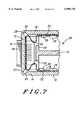
- FIG. 7is a cross-sectional view of a portion of the electronic control module as viewed along section lines 7--7 in FIG. 6.
- the present inventionis for an electronic module assembly in which a flexible circuit bearing film is mounted on a metal base plate.
- the flexible filmis bonded to the base plate, such that when the base plate is bent along a major bend axis, a non-bonded portion of the flexible film shifts away from the bend axis along an interior surface of the base plate.
- the shifting action of the flexible filmreduces stress in the film associated with the bending action of the base plate.
- the bonding arrangementalso insures that the flexible film will not become trapped against the base plate during the bending operation.
- the base plateis machined in such a way as to provide substantially a 90° angle at the major bend axis on the outside edge of the base plate.
- FIG. 1illustrates a perspective view of a planar flex circuit subassembly arranged in accordance with one embodiment of the invention.
- the subassembly 10includes a base plate 12 having integral first, second, and third sections 14, 15, and 16, respectively. Each section includes top surfaces 14a, 15a, and 16a, and bottom surfaces 14b, 15b, and 16b.
- a flexible film 18overlies base plate 12 and is bonded to top surfaces 14a, 15a, and 16a of base plate 12.
- flexible film 18is a polyimide material having a thickness of about 0.5 mm.
- Flexible film 18supports electrically conductive metal traces 20 and 21 overlying portions of top surfaces 14a and 16a, respectively.
- Metal traces 20include terminations 22 at through holes 24 in second section 15 of base plate 12.
- metal traces 21include terminations 23 at through holes 24.
- through holes 24pierce flexible film 18 and second section 15 of base plate 12, and are configured to receive electrical contact pins housed within an electrical connector.
- a plurality of electrical devices 26are attached to flexible film 18 and electrically interconnected by metal traces 20 and 21.
- base plate 12In the process for assembling an electronic control module, it is desirable to bend base plate 12 in such a way that the base plate can be coupled with an enclosure device to form a protective enclosure encasing metal traces 20 and 21 and electrical devices 26.
- base plate 12includes first and second major bend axis 27 and 28, respectively.
- Base plate 12further includes first and second grooves 29 and 30 aligned to major bend axis 27 and 28, respectively.
- First and second grooves 29 and 30extend across base plate 12 at upper surface 15a of second section 15.
- a portion of base plate 12 taken along section line 2--2is shown in FIG. 2.
- a portion of flexible film 18spans second groove 30 and is bonded to upper surfaces 15a and 16a by first and second adhesive films 31 and 32, respectively.
- First adhesive film 31has an edge 33 located a distance d 1 from major bend axis 28.
- second adhesive film 32has an edge 34 located a distance d 2 from major bend axis 28.
- a non-bonded portion 35 of flexible film 18spans distances d 1 and d 2 between edges 33 and 34.
- non-bonded portion 35shifts along third section 16 of base plate 12 in the direction of distance d 2 and away from major bend axis 28.
- non-bonded portion 35is deflected away from major bend axis 28 .
- the serpentine profile of non-bonded loop region 35reduces the space required between upper surfaces 15a and 16a for the deflection of non-bonded portion 35 when base plate 12 is bent at a 90° angle about major bend axis 28.
- non-bonded portions 35into the space between first and third sections 14 and 16 would require that second section 15 of base plate 12 have extra width. This would be necessary to avoid the possibility of metal traces overlying the non-bonded portions of the flexible film from contacting one another and creating electrical shorts. Furthermore, the serpentine deflection pattern of non-bonded portions 35 avoids the possibility of friction damage to the flexible film from rubbing against the base plate when the plate is bent.
- An electrical connector 36 housing electrical contact pins 38is mounted to second section 15 of base plate 12. Electrical contact pins 38 are inserted through through-holes 24 and make electrical contact to terminations 22 and 23 on the surface of flexible film 18.
- First adhesive film 31secures flexible film 18 to second section 15 permitting solid electrical contact between electrical contact pins 38 and terminations 22 and 23.
- first and second adhesive films 31 and 32 on upper surfaces 14a, 15a, and 16aperforms two important functions. First, as previously described, the asymmetric placement about the major bend axis beneficially causes the non-bonded portions of flexible film 18 to deflect into serpentine configurations, and second, the bonding secures a portion of flexible film 18 to base plate 12 for the attachment of an electrical connector at second section 15.
- first and second grooves 29 and 30at upper surface 15a results in a substantially 90° bend angle about first and second major bend axis 27 and 28.
- the groovesare depicted as rounded features, other geometric forms are possible.
- different geometric shapes for first and second grooves 29 and 30are possible.
- the groovescan be machined to have a "V" shape, or a "U” shape, or the like.
- the creation of substantially 90° bend angles at first and second major bend axis 27 and 28results in a lower profile height of an electronic control module assembled in accordance with the invention. Additionally, the sharp bend profile created by grooves 29 and 30 preserves a relatively high degree of flatness in lower surface 15b after base plate 12 is bent. By not causing lower surface 15b to bulge out near the bend axis, electrical connector 36 can be tightly mated to section 15 of base plate 12. The close alignment of lower surface 15b with electrical connector 36 insures that a good seal can be made around the edges of the electrical connector.
- FIG. 5An exploded assembly view of an electronic control module 40 arranged in accordance with one embodiment of the invention is illustrated in FIG. 5.
- the assembly viewillustrates the arrangement of base plate 12, flexible film 18, electrical connector 36, and an enclosure housing 42.
- flexible circuit 18is bonded to base plate 12 and metal traces 20 and 21 are defined on flexible film 18. Once the traces are defined, flexible film 18 is populated with electrical devices 26.
- base plate 12is bent around enclosure housing 42, and electrical connector 36 is inserted through apertures 44 in second section 15 of base plate 12.
- second section 15 of base plate 12includes apertures 46 that receive locating pins 48 for the alignment of electrical connector 36 to base plate 12.
- Enclosure housing 42includes a pair of arms 46 and 47 that are joined at one end by a laterally extending arm 48.
- a support arm 49extends between arms 46 and 47 and supports mandrels 50 spaced apart at predetermined distances along support arm 49.
- a brace plate 51laterally extends between arms 46 and 47, extending arm 48, and support arm 49.
- Mandrels 50extend through openings 53 in flexible film 18 and press against second section 15 of base plate 12 at the time the base plate is bent about enclosure housing 48.
- Each of the arms 46 and 47may carry a mounting foot 52, which can be used to mount electronic control module 40 to another structure.
- Sealantis placed around the periphery of base plate 12 prior to the bending operation in order to for a seal between base plate 12 and enclosure housing 42.
- the peripheral sealprevents dirt and debris from entering electronic control module 40.
- Electrical connector 36protrudes from second section 15 of base plate 12 and has connection ports 56 for receiving external electrical connections. It is important to note that the bonding of flexible film 18 to second section 15 permits electrical connector 36 to be attached to the backside of electronic control module 40. Further, the asymmetric arrangement of first and second adhesive films 31 and 32 about the major bend axis permits the overall height of electronic control module 40 to be minimized. By reducing the outside dimensions of electronic control module 40, the control module can be mounted in a small space within an automobile engine compartment.
- FIG. 7A cross-section view taken along section line 7--7 of FIG. 6 is illustrated in FIG. 7.
- Mandrel 50 ofcontacts first, second and third sections 14, 15, and 16 of base plate 12 in proximity to first and second grooves 29 and 30.
- the right-angle geometry of mandrel 50, together with grooves 29 and 30,permit base plate 12 to be bent around mandrel 50 and to form approximately 90° angles at the bend corners.
- the height of the mandrels 50 together with their positions along support arm 49determine the bend quality at the major bend axis.
- the relatively sharp angles created in base plate 12further reduces the overall size of electronic control module 40, and allows the module to be mounted in tight spaces within an automobile engine compartment.
- Enclosure housing 42cooperates with the deflection of flexible film 18 during the bending operation such that non-bonded portions 35 deflect away from support arm 49 and mandrels 50. As shown in FIG. 7, non-bonded portions 35 flex away from base plate 12 in a region of the cavity created by the bending operation located immediately away from support arm 49. Accordingly, the space within the interior cavity consumed by support arm 49, mandrels 50, and non-bonded portions 35 is minimized.
- enclosure housing 42together with the serpentine bend pattern of flexible film 18, reduce the amount of space within the cavity 58 needed to accommodate the film deflection caused by the bending operation.
- the particular arrangement illustrated in FIG. 7permits electrical devices 26 to be mounted on flexible film 18 to within about 4 mm of major bend axis 27 and 28.
- the total surface area of flexible film 18(and the volume of electronic control module 40) can be kept to a minimum value.
- more complex functionscan be performed by electronic control module 40 through adding more electronic components, such as electrical devices 26, to flexible film 18.
- first and third sections 14 and 16 of base plate 12have been illustrated as forming substantially parallel surfaces after the bending operation, it is possible to construct an electronic assembly about a single major bend axis and form a wedge shaped protective housing.
- first and third sections 14 and 16 of base plate 12have been illustrated as forming substantially parallel surfaces after the bending operation, it is possible to construct an electronic assembly about a single major bend axis and form a wedge shaped protective housing.
- the sides of the base platediverge from one another.
- the extent of bending about the major bend axiscan range from less than 90° to greater than 90°. It will be appreciated by one of skill in the art that in the case of a single major bend axis, a mandrel having a geometry substantially different from that illustrated in the embodiment disclosed herein is required.
Landscapes
- Engineering & Computer Science (AREA)
- Microelectronics & Electronic Packaging (AREA)
- Structure Of Printed Boards (AREA)
- Casings For Electric Apparatus (AREA)
Abstract
Description
This invention relates, in general, to electronic module assemblies, and more particularly, to electronic control modules having an external housing for protecting electrical components located within the module housing.
The protection of electronic components within a modular assembly is commonly carried out by attaching a flexible polyimide film to a relatively thin metal plate. A plurality of electronic components are mounted on the polyimide film and connected to conductive circuit patterns overlying the polyimide film. Once the electronic components are mounted, the metal plate is bent about a mandrel and mated with an endosure device to form a protective enclosure for the electronic devices. In one such electronic module assembly, disclosed in U.S. Pat. No. 5,170,326 to Meny, et al. and assigned to the assignee of record herein, a module enclosure meets with the base plate to form an internal cavity enclosing circuit components mounted to the polyimide flex film.
A substantial improvement in the quality and protection characteristics of electronic module assemblies has been realized by the mating of a bendable base plate with an enclosure device. The enclosure device functions to strengthen the overall structure of the completed assembly. Furthermore, the enclosure device acts as a mandrel about which the base plate can be bent. The enclosure device is not removed after the bending operation and becomes an integral portion of the overall structure. This eliminates any possibility of damage to the components on the flex film that could result during a removal of the mandrel.
In addition to providing an integral component of the overall structure, the enclosure device also provides a surface for sealing the base plate. The sealant material can be applied to the base plate prior to the bending operation to improve the manufacturability of the electronic control module. In view of the foregoing advantages realized by coupling a closure device with a bendable base plate, further development is desirable to obtain maximum utilization of the protective enclosure and to reduce the overall size of an engine control module.
FIG. 1 is a perspective view of a planar electronic subassembly in accordance with the invention;
FIG. 2 is a cross-sectional view of a portion of the subassembly of FIG. 1 taken alongsection line 2--2;
FIG. 3 shows a portion of the subassembly shown in FIG. 2 after a bending operation;
FIG. 4 is a cross-sectional view of a portion of the subassembly illustrated in FIG. 1 after attachment of an electrical connector;
FIG. 5 is an exploded perspective view of an electronic control module constructed in accordance with the invention, where some of the components being shown in a planar form prior to being bent into their final shape;
FIG. 6 is a perspective view of the electronic control module of FIG. 5 after a bending operation and assembly into its final configuration; and
FIG. 7 is a cross-sectional view of a portion of the electronic control module as viewed along section lines 7--7 in FIG. 6.
It will be appreciated that for simplicity and clarity of illustration, elements shown in the FIGURES have not necessarily been drawn to scale. For example, the dimensions of some of the elements are exaggerated relative to each other. Further, where considered appropriate, reference numerals have been repeated among the FIGURES to indicate corresponding elements.
The present invention is for an electronic module assembly in which a flexible circuit bearing film is mounted on a metal base plate. The flexible film is bonded to the base plate, such that when the base plate is bent along a major bend axis, a non-bonded portion of the flexible film shifts away from the bend axis along an interior surface of the base plate. The shifting action of the flexible film reduces stress in the film associated with the bending action of the base plate. The bonding arrangement also insures that the flexible film will not become trapped against the base plate during the bending operation. Additionally, the base plate is machined in such a way as to provide substantially a 90° angle at the major bend axis on the outside edge of the base plate. The combination of the substantial 90° angle together with the shifting of the flexible film permits the flexible film to be populated with electrical components, many of which can be placed in dose proximity to the major bend axis. These and other advantages of the invention will be appreciated upon a description of the preferred embodiments of the invention.
FIG. 1 illustrates a perspective view of a planar flex circuit subassembly arranged in accordance with one embodiment of the invention. Thesubassembly 10 includes abase plate 12 having integral first, second, andthird sections top surfaces bottom surfaces flexible film 18overlies base plate 12 and is bonded totop surfaces base plate 12. Preferably,flexible film 18 is a polyimide material having a thickness of about 0.5 mm.Flexible film 18 supports electricallyconductive metal traces top surfaces Metal traces 20 includeterminations 22 at throughholes 24 insecond section 15 ofbase plate 12. Similarly,metal traces 21 includeterminations 23 at throughholes 24. As will subsequently be described, throughholes 24 pierceflexible film 18 andsecond section 15 ofbase plate 12, and are configured to receive electrical contact pins housed within an electrical connector. A plurality ofelectrical devices 26 are attached toflexible film 18 and electrically interconnected bymetal traces
In the process for assembling an electronic control module, it is desirable tobend base plate 12 in such a way that the base plate can be coupled with an enclosure device to form a protective enclosure encasingmetal traces electrical devices 26. To facilitate the bending process,base plate 12 includes first and secondmajor bend axis Base plate 12 further includes first andsecond grooves major bend axis second grooves base plate 12 atupper surface 15a ofsecond section 15.
A portion ofbase plate 12 taken alongsection line 2--2 is shown in FIG. 2. A portion offlexible film 18 spanssecond groove 30 and is bonded toupper surfaces adhesive films adhesive film 31 has anedge 33 located a distance d1 frommajor bend axis 28. Correspondingly, secondadhesive film 32 has anedge 34 located a distance d2 frommajor bend axis 28. A non-bondedportion 35 offlexible film 18 spans distances d1 and d2 betweenedges adhesive layers base plate 12, a gap is created between the adhesive layers that is asymmetrically centered aboutmajor bend axis 28. Distance d2 defines the extent of the gap alongthird section 16 ofbase plate 12. Correspondingly, distance d1 defines the extent of the gap alongsecond section 15 ofbase plate 12.
The asymmetrical centering of the gap between first and secondadhesive films portion 35 whenbase plate 12 is bent aboutmajor bend axis 28. As shown in FIG. 3,non-bonded portion 35 shifts alongthird section 16 ofbase plate 12 in the direction of distance d2 and away frommajor bend axis 28. By selectively locating first and secondadhesive films base plate 12, the direction of the deformation profile of non-bondedportion 35 can be controlled at thetime base plate 12 is bent aboutmajor bend axis 28. The deflection ofnon-bonded portion 35 alongupper surface 16b permitselectrical devices 26 to be mounted onflexible film 18 in close proximity tomajor bend axis 28. Additionally by deflecting non-bondedportion 35 away frommajor bend axis 28, a serpentine fold is created inflexible film 18. The serpentine profile ofnon-bonded loop region 35 reduces the space required betweenupper surfaces non-bonded portion 35 whenbase plate 12 is bent at a 90° angle aboutmajor bend axis 28.
The advantages of creating a serpentine profile and deflectingnon-bonded portion 35 offlexible film 18 away from the major bend axis is illustrated in the partial cross-section shown in FIG. 4. Whenbase plate 12 is bent about first and secondmajor bend axis portions 35 deflect along first andthird sections adhesive films flexible film 18 into serpentine patterns at the major bend axis permitsfirst section 14 andthird section 16 ofbase plate 12 to be brought into close proximity with each other.
Those skilled in the art will appreciate that a simple parabolic deflection ofnon-bonded portions 35 into the space between first andthird sections second section 15 ofbase plate 12 have extra width. This would be necessary to avoid the possibility of metal traces overlying the non-bonded portions of the flexible film from contacting one another and creating electrical shorts. Furthermore, the serpentine deflection pattern ofnon-bonded portions 35 avoids the possibility of friction damage to the flexible film from rubbing against the base plate when the plate is bent.
Anelectrical connector 36 housing electrical contact pins 38 is mounted tosecond section 15 ofbase plate 12. Electrical contact pins 38 are inserted through through-holes 24 and make electrical contact to terminations 22 and 23 on the surface offlexible film 18. Firstadhesive film 31 securesflexible film 18 tosecond section 15 permitting solid electrical contact between electrical contact pins 38 andterminations adhesive films upper surfaces flexible film 18 to deflect into serpentine configurations, and second, the bonding secures a portion offlexible film 18 tobase plate 12 for the attachment of an electrical connector atsecond section 15.
It is important to note that the placement of first andsecond grooves upper surface 15a results in a substantially 90° bend angle about first and secondmajor bend axis second grooves
As will subsequently be described, the creation of substantially 90° bend angles at first and secondmajor bend axis grooves lower surface 15b afterbase plate 12 is bent. By not causinglower surface 15b to bulge out near the bend axis,electrical connector 36 can be tightly mated tosection 15 ofbase plate 12. The close alignment oflower surface 15b withelectrical connector 36 insures that a good seal can be made around the edges of the electrical connector.
An exploded assembly view of anelectronic control module 40 arranged in accordance with one embodiment of the invention is illustrated in FIG. 5. The assembly view illustrates the arrangement ofbase plate 12,flexible film 18,electrical connector 36, and anenclosure housing 42. In an assembly process,flexible circuit 18 is bonded tobase plate 12 and metal traces 20 and 21 are defined onflexible film 18. Once the traces are defined,flexible film 18 is populated withelectrical devices 26. Then,base plate 12 is bent aroundenclosure housing 42, andelectrical connector 36 is inserted throughapertures 44 insecond section 15 ofbase plate 12. In addition,second section 15 ofbase plate 12 includesapertures 46 that receive locatingpins 48 for the alignment ofelectrical connector 36 tobase plate 12.
Sealant is placed around the periphery ofbase plate 12 prior to the bending operation in order to for a seal betweenbase plate 12 andenclosure housing 42. The peripheral seal prevents dirt and debris from enteringelectronic control module 40. Oncebase plate 12 is bent aroundenclosure housing 48, the base plate is secured toenclosure housing 48 by attachment means 54, as shown in FIG. 6.Electrical connector 36 protrudes fromsecond section 15 ofbase plate 12 and hasconnection ports 56 for receiving external electrical connections. It is important to note that the bonding offlexible film 18 tosecond section 15 permitselectrical connector 36 to be attached to the backside ofelectronic control module 40. Further, the asymmetric arrangement of first and secondadhesive films electronic control module 40 to be minimized. By reducing the outside dimensions ofelectronic control module 40, the control module can be mounted in a small space within an automobile engine compartment.
A cross-section view taken along section line 7--7 of FIG. 6 is illustrated in FIG. 7.Mandrel 50 of contacts first, second andthird sections base plate 12 in proximity to first andsecond grooves mandrel 50, together withgrooves permit base plate 12 to be bent aroundmandrel 50 and to form approximately 90° angles at the bend corners. It is important to note that the height of themandrels 50 together with their positions alongsupport arm 49 determine the bend quality at the major bend axis. The relatively sharp angles created inbase plate 12 further reduces the overall size ofelectronic control module 40, and allows the module to be mounted in tight spaces within an automobile engine compartment.
The geometric arrangement ofenclosure housing 42, together with the serpentine bend pattern offlexible film 18, reduce the amount of space within thecavity 58 needed to accommodate the film deflection caused by the bending operation. Furthermore, the particular arrangement illustrated in FIG. 7 permitselectrical devices 26 to be mounted onflexible film 18 to within about 4 mm ofmajor bend axis electronic control module 40 through adding more electronic components, such aselectrical devices 26, toflexible film 18.
Those skilled in the art will appreciate that the asymmetrical bonding of a flexible film about a major bend axis can be advantageously employed in a variety of geometric configurations for the formation of a modular electronic assembly. For example, although first andthird sections base plate 12 have been illustrated as forming substantially parallel surfaces after the bending operation, it is possible to construct an electronic assembly about a single major bend axis and form a wedge shaped protective housing. In the case of a single major bend axis, upon bending about the axis, the sides of the base plate diverge from one another. Also, the extent of bending about the major bend axis can range from less than 90° to greater than 90°. It will be appreciated by one of skill in the art that in the case of a single major bend axis, a mandrel having a geometry substantially different from that illustrated in the embodiment disclosed herein is required.
Thus it is apparent that there has been provided, in accordance with the invention, an electronic control module which fully meets the advantages set forth above. Although the invention has been described and illustrated with reference to specific illustrative embodiments thereof, it is not intended that the invention be limited to those illustrative embodiments. Those skilled in the art will recognize that variations and modifications can be made without departing from the spirit of the invention. For example, the electronic control module can have different external geometry, such a rectangular, square, pie shaped, and the like. It is therefore intended to include within the invention all such variations and modifications as fall within the scope of the appended claims and equivalents thereof.
Claims (12)
1. An electronic control module comprising:
a base plate having opposing first and second planar surfaces and a major bend axis extending across the base plate;
a flexible film overlying the first planar surface of the base plate and having first and second portions bonded thereto;
a first adhesive layer intermediate to the flexible film and the base plate and bonding the first portion of the flexible film to the first planar surface of the base plate,
wherein the first adhesive layer has an edge proximate to the major bend axis located a first distance from the major bend axis; and
a second adhesive layer intermediate to the flexible film and the base plate bonding the second portion of the flexible film to the first planar surface of the base plate,
wherein the second adhesive layer has an edge proximate to the major bend axis located a second distance from the major bend axis, and
wherein a non-bonded portion of the flexible film spans the first and second distances, and
wherein the first distance is substantially unequal to the second distance.
2. The electronic control module of claim 1, wherein the first and second adhesive layers comprise a pressure sensitive adhesive, and wherein the flexible film comprises a flexible polyimide material.
3. The electronic control module of claim 1, wherein the base plate is bent over on itself by approximately 180° along the major bend axis, and wherein the non-bonded loop portion is laterally shifted away from the major bend axis toward one of the first and second sections of the flexible film.
4. An electronic control module of claim 1, further comprising:
a groove in the first planar surface coextensive with the major bend axis; and
wherein the non-bonded bracket portion of the flexible film spans the groove.
5. An electronic control module comprising:
a base plate having opposing first and second planar surfaces and having first and second major bend axes extending widthwise across the base plate,
wherein the first and second major bend axes are separated by a central section of the base plate;
an insulating film overlying the first planar surface of the base plate and having first, second, and third portions bonded thereto;
a first adhesive layer bonding the first portion of the insulating film to the first planar surface,
wherein the first adhesive layer has first and second edges located a first distance from the first major bend axis and the second major bend axis, respectively;
a first region of the second adhesive layer bonding the second portion of the insulating film to the first planar surface,
wherein the first region of the second adhesive layer has an edge located a second distance from the first major bend axis; and
a second region of the second adhesive layer bonding the third portion of the insulating film to the first planar surface,
wherein the second region of the second adhesive layer has a first edge located at a third distance from the second major bend axis, and
wherein the first and second distances are substantially unequal.
6. The electronic control module of claim 5 further comprising:
a plurality of conductors carried by the insulating film and having terminations located in proximity to the central section; and
a connector inserted through an opening in the central section and coupled to the terminations for electrically connecting the plurality of conductors to external devices.
7. The electronic control module of claim 5 further comprising:
first and second grooves in the first planar surface and coextensive with the first and second major bend axes, respectively; and
portions of the insulating film spanning the first and second grooves.
8. An electronic control module comprising:
a base plate having a first major bend axis extending across the base plate,
wherein the base plate is bent over on itself along the first major bend axis to provide a cavity at least partially enclosed by first and second interior surfaces;
a flexible insulating film overlying the first and second interior surfaces and bonded thereto; and
an adhesive layer intermediate to the base plate and the flexible insulating film and having a gap therein,
wherein the gap is asymmetrically centered about the first major bend axis, and
wherein a non-bonded loop portion of the flexible insulating film spans the gap and is displaced away from the first major bend axis along one of the first and second interior surfaces.
9. The electronic control module of claim 8, wherein the first and second interior surfaces are substantially parallel.
10. The electronic control module of claim 8 further comprising:
a second major bend axis;
a back section of the base plate intermediate to the first and second major bend axes; and
a portion of the flexible insulating film bonded to the back section.
11. The electronic control module of claim 10 further comprising:
a plurality of conductors carried by the flexible insulating film and having terminations located in proximity to the back section; and
a connector inserted through an opening in the back section and coupled to the terminations for electrically connecting the plurality of conductors to external devices.
12. An electronic control module comprising:
a base plate having first and second major bend axes along which the base plate is bent in a "U" shape to provide an inner surface, the inner surface having first and second elongated sections separated by a back section; and
a flexible circuit-carrying film bonded to a substantial area of the inner surface and having non-bonded loop portions displaced away from the first and second major bend axes along the first and second elongated sections,
wherein, the non-bonded loop portions are asymmetrically displaced from the first and second major bend axes.
Priority Applications (3)
| Application Number | Priority Date | Filing Date | Title |
|---|---|---|---|
| US08/706,014US5998738A (en) | 1996-08-30 | 1996-08-30 | Electronic control module |
| EP97113468AEP0827372B1 (en) | 1996-08-30 | 1997-08-05 | Electronic control module |
| DE69731047TDE69731047T2 (en) | 1996-08-30 | 1997-08-05 | Electronic control module |
Applications Claiming Priority (1)
| Application Number | Priority Date | Filing Date | Title |
|---|---|---|---|
| US08/706,014US5998738A (en) | 1996-08-30 | 1996-08-30 | Electronic control module |
Publications (1)
| Publication Number | Publication Date |
|---|---|
| US5998738Atrue US5998738A (en) | 1999-12-07 |
Family
ID=24835864
Family Applications (1)
| Application Number | Title | Priority Date | Filing Date |
|---|---|---|---|
| US08/706,014Expired - LifetimeUS5998738A (en) | 1996-08-30 | 1996-08-30 | Electronic control module |
Country Status (3)
| Country | Link |
|---|---|
| US (1) | US5998738A (en) |
| EP (1) | EP0827372B1 (en) |
| DE (1) | DE69731047T2 (en) |
Cited By (40)
| Publication number | Priority date | Publication date | Assignee | Title |
|---|---|---|---|---|
| US20020048974A1 (en)* | 2000-10-19 | 2002-04-25 | Kurt Michel | Electrical component housing structures and their method of manfacture |
| US6396692B1 (en) | 2000-07-27 | 2002-05-28 | Motorola, Inc. | Electronic control unit with integrated cooling module |
| US20020068389A1 (en)* | 2000-12-01 | 2002-06-06 | Koninklijke Philips Electronics N.V. | Fexible electronic device |
| US6477052B1 (en) | 2000-08-01 | 2002-11-05 | Daimlerchrysler Corporation | Multiple layer thin flexible circuit board |
| US6501661B1 (en)* | 2001-12-21 | 2002-12-31 | Motorola, Inc. | Electronic control unit |
| US20030049886A1 (en)* | 2001-09-07 | 2003-03-13 | Salmon Peter C. | Electronic system modules and method of fabrication |
| US6570089B1 (en)* | 2002-06-18 | 2003-05-27 | Delphi Technologies, Inc. | Automotive electronics control module enclosure |
| WO2003045120A1 (en)* | 2001-11-16 | 2003-05-30 | Motorola, Inc., A Corporation Of The State Of Delaware | Method and apparatus for securing a circuit board to a rigid surface |
| US6655017B1 (en)* | 2000-05-03 | 2003-12-02 | Deere & Company | Electronic controller unit and method of manufacturing same |
| US20040020687A1 (en)* | 2002-07-31 | 2004-02-05 | Moore Kevin D. | Flexible circuit board having electrical resistance heater trace |
| US20040092141A1 (en)* | 2001-09-07 | 2004-05-13 | Salmon Peter C. | Electronic system modules and method of fabrication |
| US20040101993A1 (en)* | 2001-09-07 | 2004-05-27 | Salmon Peter C. | Component connections using bumps and wells |
| US20040178539A1 (en)* | 2003-03-14 | 2004-09-16 | David Fiedler | System and method for bending a substantially rigid substrate |
| US20050056457A1 (en)* | 2003-09-11 | 2005-03-17 | Gall Thomas P. | Electronic control unit |
| US20050122694A1 (en)* | 2003-11-14 | 2005-06-09 | Kane Vincent M. | Sealed header and method of making |
| US6927344B1 (en) | 2004-02-27 | 2005-08-09 | Motorola, Inc. | Flexible circuit board assembly |
| US20050255722A1 (en)* | 2004-05-07 | 2005-11-17 | Salmon Peter C | Micro blade assembly |
| US20060131728A1 (en)* | 2004-12-16 | 2006-06-22 | Salmon Peter C | Repairable three-dimensional semiconductor subsystem |
| US20060267180A1 (en)* | 2005-05-25 | 2006-11-30 | Kenzo Danjo | Heat sink arrangement for electrical apparatus |
| US20070116932A1 (en)* | 2003-10-04 | 2007-05-24 | Koninklijke Philips Electronics N.V. | Device and method of making a device having a flexible layer structure |
| US7408258B2 (en) | 2003-08-20 | 2008-08-05 | Salmon Technologies, Llc | Interconnection circuit and electronic module utilizing same |
| US7505862B2 (en) | 2003-03-07 | 2009-03-17 | Salmon Technologies, Llc | Apparatus and method for testing electronic systems |
| DE102007046639A1 (en)* | 2007-09-27 | 2009-04-02 | Büchner, Thomas | Electrical printed circuit board arrangement i.e. LED-illumination device, for illuminating objects, has carrier plate sections bent in angular position along material attenuation regions i.e. material bridges |
| US7586747B2 (en) | 2005-08-01 | 2009-09-08 | Salmon Technologies, Llc. | Scalable subsystem architecture having integrated cooling channels |
| US20100263900A1 (en)* | 2009-04-20 | 2010-10-21 | Divincenzo Gregory | Reconfigurable full authority digital electronic control housing |
| CN102101456A (en)* | 2009-12-22 | 2011-06-22 | 汽车照明罗伊特林根有限公司 | Electronic control device and gas discharge lamp for a lighting device of a motor vehicle with such a control device |
| US20110149522A1 (en)* | 2009-12-22 | 2011-06-23 | Christian Johann | Electronic control unit and method for producing component of same |
| US20110274866A1 (en)* | 2007-07-13 | 2011-11-10 | Foxconn Advanced Technology Inc. | Inner substrate for manufacturing multilayer printed circuit boards |
| DE102010025591A1 (en)* | 2010-06-29 | 2011-12-29 | Conti Temic Microelectronic Gmbh | Sensor carrier and sensor module in particular for use in a motor vehicle suburb control unit |
| US20140090243A1 (en)* | 2010-12-20 | 2014-04-03 | Biotronik Se & Co. Kg | In-Situ Fold-Assisting Frame for Flexible Substrates |
| US20140104792A1 (en)* | 2012-10-11 | 2014-04-17 | Apple Inc. | Devices Having Flexible Printed Circuits With Bent Stiffeners |
| US20140311777A1 (en)* | 2011-11-16 | 2014-10-23 | Lg Innotek Co., Ltd. | Bent printed circuit board for backlight unit |
| US9521748B1 (en)* | 2013-12-09 | 2016-12-13 | Multek Technologies, Ltd. | Mechanical measures to limit stress and strain in deformable electronics |
| US9554465B1 (en) | 2013-08-27 | 2017-01-24 | Flextronics Ap, Llc | Stretchable conductor design and methods of making |
| US20170086311A1 (en)* | 2014-06-19 | 2017-03-23 | Bae Systems Information And Electronic Systems Integration Inc. | Dense out of plane interconnect inside hermetically sealed modules |
| US9839125B1 (en) | 2013-12-09 | 2017-12-05 | Flextronics Ap, Llc | Methods of interconnecting components on fabrics using metal braids |
| WO2018036588A1 (en)* | 2016-08-24 | 2018-03-01 | Harting Electric Gmbh & Co. Kg | Plug-in connector |
| US20190150269A1 (en)* | 2017-11-15 | 2019-05-16 | Steering Solutions Ip Holding Corporation | Semi-flexible ridged printed circuit board assembly |
| US10568219B2 (en)* | 2017-12-13 | 2020-02-18 | Hyundai Autron Co., Ltd. | Electronic control device |
| US12445020B2 (en) | 2019-11-22 | 2025-10-14 | Innomotics Gmbh | Drive with segmented inverter housing |
Families Citing this family (6)
| Publication number | Priority date | Publication date | Assignee | Title |
|---|---|---|---|---|
| DE20108532U1 (en)* | 2001-05-21 | 2001-09-13 | Coroplast Fritz Müller GmbH & Co. KG, 42279 Wuppertal | Foil conductors, such as foil conductor cables or plates |
| DE202007005076U1 (en)* | 2007-04-05 | 2007-08-02 | Kiekert Ag | Component carrier for locking systems |
| EP2506691A1 (en)* | 2011-10-12 | 2012-10-03 | Continental Automotive GmbH | Housing for control units |
| DE102011119841B4 (en)* | 2011-12-01 | 2013-12-12 | I F M Electronic Gmbh | Electronic unit, method for manufacturing an electronic unit and electronic meter with an electronic unit |
| DE102013209296B4 (en)* | 2013-05-21 | 2024-04-18 | Vitesco Technologies GmbH | Electronic module, in particular control unit for a vehicle |
| US10973125B2 (en)* | 2019-06-28 | 2021-04-06 | Hamilton Sundstrand Corporation | Flex board spacer |
Citations (8)
| Publication number | Priority date | Publication date | Assignee | Title |
|---|---|---|---|---|
| US4626462A (en)* | 1984-09-21 | 1986-12-02 | Firma Carl Freundenberg | Process for the manufacture of through-hole contacted flexible circuit boards for high bending stresses and the circuit boards made therefrom |
| US4811165A (en)* | 1987-12-07 | 1989-03-07 | Motorola, Inc. | Assembly for circuit modules |
| US5103375A (en)* | 1990-02-05 | 1992-04-07 | Motorola, Inc. | Electronic module assembly and method of manufacture |
| US5159751A (en)* | 1990-02-05 | 1992-11-03 | Motorola, Inc. | Method of manufacturing electronic module assembly |
| US5170326A (en)* | 1990-02-05 | 1992-12-08 | Motorola, Inc. | Electronic module assembly |
| US5179501A (en)* | 1992-02-24 | 1993-01-12 | Motorola, Inc. | Laminated electronic module assembly |
| US5216581A (en)* | 1990-02-05 | 1993-06-01 | Motorola, Inc. | Electronic module assembly and method of forming same |
| US5265322A (en)* | 1990-02-05 | 1993-11-30 | Motorola, Inc. | Electronic module assembly and method of forming same |
Family Cites Families (2)
| Publication number | Priority date | Publication date | Assignee | Title |
|---|---|---|---|---|
| US5434362A (en)* | 1994-09-06 | 1995-07-18 | Motorola, Inc. | Flexible circuit board assembly and method |
| FR2725107B1 (en)* | 1994-09-26 | 1996-12-13 | Siemens Automotive Sa | SPACERS AND ELECTRONIC CONTROL UNIT COMPRISING SUCH SPACERS |
- 1996
- 1996-08-30USUS08/706,014patent/US5998738A/ennot_activeExpired - Lifetime
- 1997
- 1997-08-05EPEP97113468Apatent/EP0827372B1/ennot_activeExpired - Lifetime
- 1997-08-05DEDE69731047Tpatent/DE69731047T2/ennot_activeExpired - Lifetime
Patent Citations (8)
| Publication number | Priority date | Publication date | Assignee | Title |
|---|---|---|---|---|
| US4626462A (en)* | 1984-09-21 | 1986-12-02 | Firma Carl Freundenberg | Process for the manufacture of through-hole contacted flexible circuit boards for high bending stresses and the circuit boards made therefrom |
| US4811165A (en)* | 1987-12-07 | 1989-03-07 | Motorola, Inc. | Assembly for circuit modules |
| US5103375A (en)* | 1990-02-05 | 1992-04-07 | Motorola, Inc. | Electronic module assembly and method of manufacture |
| US5159751A (en)* | 1990-02-05 | 1992-11-03 | Motorola, Inc. | Method of manufacturing electronic module assembly |
| US5170326A (en)* | 1990-02-05 | 1992-12-08 | Motorola, Inc. | Electronic module assembly |
| US5216581A (en)* | 1990-02-05 | 1993-06-01 | Motorola, Inc. | Electronic module assembly and method of forming same |
| US5265322A (en)* | 1990-02-05 | 1993-11-30 | Motorola, Inc. | Electronic module assembly and method of forming same |
| US5179501A (en)* | 1992-02-24 | 1993-01-12 | Motorola, Inc. | Laminated electronic module assembly |
Cited By (78)
| Publication number | Priority date | Publication date | Assignee | Title |
|---|---|---|---|---|
| US6655017B1 (en)* | 2000-05-03 | 2003-12-02 | Deere & Company | Electronic controller unit and method of manufacturing same |
| US6396692B1 (en) | 2000-07-27 | 2002-05-28 | Motorola, Inc. | Electronic control unit with integrated cooling module |
| US6477052B1 (en) | 2000-08-01 | 2002-11-05 | Daimlerchrysler Corporation | Multiple layer thin flexible circuit board |
| US20020048974A1 (en)* | 2000-10-19 | 2002-04-25 | Kurt Michel | Electrical component housing structures and their method of manfacture |
| US6700074B2 (en)* | 2000-10-19 | 2004-03-02 | Cherry Gmbh | Electrical component housing structures and their method of manufacture |
| US20020068389A1 (en)* | 2000-12-01 | 2002-06-06 | Koninklijke Philips Electronics N.V. | Fexible electronic device |
| US6798052B2 (en)* | 2000-12-01 | 2004-09-28 | Koninklijke Philips Electronics N.V. | Fexible electronic device |
| US20100007012A1 (en)* | 2001-09-07 | 2010-01-14 | Hynix Semiconductor Inc. | Electronic system modules |
| US20090243076A1 (en)* | 2001-09-07 | 2009-10-01 | Hynix Semiconductor, Inc. | Electronic system modules and method of fabrication |
| US20080079140A1 (en)* | 2001-09-07 | 2008-04-03 | Hynix Semiconductor, Inc. | Electronic system modules and method of fabricaton |
| US20080026557A1 (en)* | 2001-09-07 | 2008-01-31 | Hynix Semiconductor, Inc. | Electronic system modules and method of fabrication |
| US20040092141A1 (en)* | 2001-09-07 | 2004-05-13 | Salmon Peter C. | Electronic system modules and method of fabrication |
| US20040101993A1 (en)* | 2001-09-07 | 2004-05-27 | Salmon Peter C. | Component connections using bumps and wells |
| US7297572B2 (en) | 2001-09-07 | 2007-11-20 | Hynix Semiconductor, Inc. | Fabrication method for electronic system modules |
| US20030049886A1 (en)* | 2001-09-07 | 2003-03-13 | Salmon Peter C. | Electronic system modules and method of fabrication |
| US20070245554A1 (en)* | 2001-09-07 | 2007-10-25 | Hynix Semiconductor, Inc. | Fabrication Method For Electronic System Modules |
| US9059070B2 (en) | 2001-09-07 | 2015-06-16 | SK Hynix Inc. | Electronic system modules and method of fabrication |
| US6881609B2 (en) | 2001-09-07 | 2005-04-19 | Peter C. Salmon | Component connections using bumps and wells |
| US7615478B2 (en) | 2001-09-07 | 2009-11-10 | Hynix Semiconductor Inc. | Fabrication method for electronic system modules |
| US8633584B2 (en) | 2001-09-07 | 2014-01-21 | SK Hynix Inc. | Electronic assembly with electronic compontent and interconnection assembly connected via conductive bump and mating well |
| US7723156B2 (en) | 2001-09-07 | 2010-05-25 | Hynix Semiconductor Inc. | Electronic system modules and method of fabrication |
| US20050140026A1 (en)* | 2001-09-07 | 2005-06-30 | Salmon Peter C. | Fabrication methods for electronic system modules |
| US8581407B2 (en) | 2001-09-07 | 2013-11-12 | SK Hynix Inc. | Electronic system modules and method of fabrication |
| US6927471B2 (en) | 2001-09-07 | 2005-08-09 | Peter C. Salmon | Electronic system modules and method of fabrication |
| US8252635B2 (en) | 2001-09-07 | 2012-08-28 | Hynix Semiconductor Inc. | Electronic system modules and method of fabrication |
| US20100297814A1 (en)* | 2001-09-07 | 2010-11-25 | Hynix Semiconductor Inc. | Electronic system modules and method of fabrication |
| WO2003045120A1 (en)* | 2001-11-16 | 2003-05-30 | Motorola, Inc., A Corporation Of The State Of Delaware | Method and apparatus for securing a circuit board to a rigid surface |
| US6501661B1 (en)* | 2001-12-21 | 2002-12-31 | Motorola, Inc. | Electronic control unit |
| US6570089B1 (en)* | 2002-06-18 | 2003-05-27 | Delphi Technologies, Inc. | Automotive electronics control module enclosure |
| US6841739B2 (en) | 2002-07-31 | 2005-01-11 | Motorola, Inc. | Flexible circuit board having electrical resistance heater trace |
| US20040020687A1 (en)* | 2002-07-31 | 2004-02-05 | Moore Kevin D. | Flexible circuit board having electrical resistance heater trace |
| US20090192753A1 (en)* | 2003-03-07 | 2009-07-30 | Salmon Peter C | Apparatus and method for testing electronic systems |
| US7505862B2 (en) | 2003-03-07 | 2009-03-17 | Salmon Technologies, Llc | Apparatus and method for testing electronic systems |
| US6908583B2 (en) | 2003-03-14 | 2005-06-21 | Motorola, Inc. | System and method for bending a substantially rigid substrate |
| US20040178539A1 (en)* | 2003-03-14 | 2004-09-16 | David Fiedler | System and method for bending a substantially rigid substrate |
| US7408258B2 (en) | 2003-08-20 | 2008-08-05 | Salmon Technologies, Llc | Interconnection circuit and electronic module utilizing same |
| WO2005036938A1 (en)* | 2003-09-11 | 2005-04-21 | Motorola Inc. | Electronic control unit |
| CN100346677C (en)* | 2003-09-11 | 2007-10-31 | 摩托罗拉公司 | Electronic control unit |
| US20050056457A1 (en)* | 2003-09-11 | 2005-03-17 | Gall Thomas P. | Electronic control unit |
| US7075794B2 (en) | 2003-09-11 | 2006-07-11 | Motorola, Inc. | Electronic control unit |
| US20070116932A1 (en)* | 2003-10-04 | 2007-05-24 | Koninklijke Philips Electronics N.V. | Device and method of making a device having a flexible layer structure |
| US7492600B2 (en) | 2003-11-14 | 2009-02-17 | Tyco Electronics Corporation | Sealed header and method of making |
| US20050122694A1 (en)* | 2003-11-14 | 2005-06-09 | Kane Vincent M. | Sealed header and method of making |
| US6927344B1 (en) | 2004-02-27 | 2005-08-09 | Motorola, Inc. | Flexible circuit board assembly |
| US20050190531A1 (en)* | 2004-02-27 | 2005-09-01 | Gall Thomas P. | Flexible circuit board assembly |
| WO2005094143A1 (en)* | 2004-02-27 | 2005-10-06 | Motorola, Inc. | Flexible circuit board assembly |
| US20050255722A1 (en)* | 2004-05-07 | 2005-11-17 | Salmon Peter C | Micro blade assembly |
| US20060131728A1 (en)* | 2004-12-16 | 2006-06-22 | Salmon Peter C | Repairable three-dimensional semiconductor subsystem |
| US7427809B2 (en) | 2004-12-16 | 2008-09-23 | Salmon Technologies, Llc | Repairable three-dimensional semiconductor subsystem |
| CN100562216C (en)* | 2005-05-25 | 2009-11-18 | 株式会社三社电机制作所 | The heat abstractor that is used for electric equipment |
| US7579554B2 (en)* | 2005-05-25 | 2009-08-25 | Sansha Electric Manufacturing Company Limited | Heat sink arrangement for electrical apparatus |
| US20060267180A1 (en)* | 2005-05-25 | 2006-11-30 | Kenzo Danjo | Heat sink arrangement for electrical apparatus |
| US7586747B2 (en) | 2005-08-01 | 2009-09-08 | Salmon Technologies, Llc. | Scalable subsystem architecture having integrated cooling channels |
| US20110274866A1 (en)* | 2007-07-13 | 2011-11-10 | Foxconn Advanced Technology Inc. | Inner substrate for manufacturing multilayer printed circuit boards |
| DE102007046639A1 (en)* | 2007-09-27 | 2009-04-02 | Büchner, Thomas | Electrical printed circuit board arrangement i.e. LED-illumination device, for illuminating objects, has carrier plate sections bent in angular position along material attenuation regions i.e. material bridges |
| US20100263900A1 (en)* | 2009-04-20 | 2010-10-21 | Divincenzo Gregory | Reconfigurable full authority digital electronic control housing |
| US8520392B2 (en)* | 2009-12-22 | 2013-08-27 | Automotive Lighting Reutlingen Gmbh | Electronic control unit and method for producing component of same |
| US20110149522A1 (en)* | 2009-12-22 | 2011-06-23 | Christian Johann | Electronic control unit and method for producing component of same |
| CN102101456A (en)* | 2009-12-22 | 2011-06-22 | 汽车照明罗伊特林根有限公司 | Electronic control device and gas discharge lamp for a lighting device of a motor vehicle with such a control device |
| DE102010025591A1 (en)* | 2010-06-29 | 2011-12-29 | Conti Temic Microelectronic Gmbh | Sensor carrier and sensor module in particular for use in a motor vehicle suburb control unit |
| US9119317B2 (en)* | 2010-12-20 | 2015-08-25 | Biotronik Se & Co. Kg | Method of folding flexible substrate in-situ using fold-assisting frame |
| US20140090243A1 (en)* | 2010-12-20 | 2014-04-03 | Biotronik Se & Co. Kg | In-Situ Fold-Assisting Frame for Flexible Substrates |
| US9326382B2 (en)* | 2011-11-16 | 2016-04-26 | Lg Innotek Co., Ltd. | Bent printed circuit board for backlight unit |
| US20140311777A1 (en)* | 2011-11-16 | 2014-10-23 | Lg Innotek Co., Ltd. | Bent printed circuit board for backlight unit |
| US9019710B2 (en)* | 2012-10-11 | 2015-04-28 | Apple Inc. | Devices having flexible printed circuits with bent stiffeners |
| US20140104792A1 (en)* | 2012-10-11 | 2014-04-17 | Apple Inc. | Devices Having Flexible Printed Circuits With Bent Stiffeners |
| US9554465B1 (en) | 2013-08-27 | 2017-01-24 | Flextronics Ap, Llc | Stretchable conductor design and methods of making |
| US9521748B1 (en)* | 2013-12-09 | 2016-12-13 | Multek Technologies, Ltd. | Mechanical measures to limit stress and strain in deformable electronics |
| US9839125B1 (en) | 2013-12-09 | 2017-12-05 | Flextronics Ap, Llc | Methods of interconnecting components on fabrics using metal braids |
| US20170086311A1 (en)* | 2014-06-19 | 2017-03-23 | Bae Systems Information And Electronic Systems Integration Inc. | Dense out of plane interconnect inside hermetically sealed modules |
| US9642265B2 (en)* | 2014-06-19 | 2017-05-02 | Bae Systems Information And Electronic Systems Integration Inc. | Dense out of plane interconnect inside hermetically sealed modules |
| WO2018036588A1 (en)* | 2016-08-24 | 2018-03-01 | Harting Electric Gmbh & Co. Kg | Plug-in connector |
| CN109643865A (en)* | 2016-08-24 | 2019-04-16 | 哈廷电子有限公司及两合公司 | plug connector |
| US11201441B2 (en) | 2016-08-24 | 2021-12-14 | Harting Electric Gmbh & Co. Kg | Plug-in connector |
| US20190150269A1 (en)* | 2017-11-15 | 2019-05-16 | Steering Solutions Ip Holding Corporation | Semi-flexible ridged printed circuit board assembly |
| US11109478B2 (en)* | 2017-11-15 | 2021-08-31 | Steering Solutions Ip Holding Corporation | Semi-flexible ridged printed circuit board assembly |
| US10568219B2 (en)* | 2017-12-13 | 2020-02-18 | Hyundai Autron Co., Ltd. | Electronic control device |
| US12445020B2 (en) | 2019-11-22 | 2025-10-14 | Innomotics Gmbh | Drive with segmented inverter housing |
Also Published As
| Publication number | Publication date |
|---|---|
| EP0827372A2 (en) | 1998-03-04 |
| DE69731047T2 (en) | 2005-02-17 |
| DE69731047D1 (en) | 2004-11-11 |
| EP0827372B1 (en) | 2004-10-06 |
| EP0827372A3 (en) | 1998-05-06 |
Similar Documents
| Publication | Publication Date | Title |
|---|---|---|
| US5998738A (en) | Electronic control module | |
| US5103375A (en) | Electronic module assembly and method of manufacture | |
| US5170326A (en) | Electronic module assembly | |
| US5265322A (en) | Electronic module assembly and method of forming same | |
| JP3784836B2 (en) | Connector preferably is a right angle connector with an integrated PCB assembly | |
| US5240420A (en) | Self-aligning high-density printed circuit connector | |
| EP0557883B1 (en) | Laminated electronic module assembly | |
| JP3456426B2 (en) | Electronic control unit | |
| US5159751A (en) | Method of manufacturing electronic module assembly | |
| CN100576657C (en) | Electrical adapters and their components | |
| US5216581A (en) | Electronic module assembly and method of forming same | |
| JP6592995B2 (en) | Electrical connector | |
| JPH07302649A (en) | Connector of cable for high frequency signal | |
| JPH0613136A (en) | Coaxial connector module | |
| JP2006173051A (en) | Connector | |
| EP1152649B1 (en) | Electronic controller unit and method of manufacturing | |
| US5954537A (en) | Flexible flat cable and connector for connecting the same | |
| EP0226276B1 (en) | Electrical connection assembly for interconnecting a flexible circuit and another circuit means | |
| JP2922645B2 (en) | Electronic module assembly | |
| JPH04313299A (en) | Mounting structure in electronic equipment | |
| JPH0645397U (en) | Shield plate fixed structure | |
| JPH08273766A (en) | Connector with built-in filter | |
| JP3178575B2 (en) | Flexible circuit board harness device | |
| JP2970952B2 (en) | Semiconductor device and manufacturing method thereof | |
| JPH04143732A (en) | Connection structure of liquid crystal display element |
Legal Events
| Date | Code | Title | Description |
|---|---|---|---|
| AS | Assignment | Owner name:MOTOROLA, INC., ILLINOIS Free format text:ASSIGNMENT OF ASSIGNORS INTEREST;ASSIGNORS:LI, RONALD;MCKERNAN, AMY;REEL/FRAME:008190/0948 Effective date:19960830 | |
| STCF | Information on status: patent grant | Free format text:PATENTED CASE | |
| FPAY | Fee payment | Year of fee payment:4 | |
| REMI | Maintenance fee reminder mailed | ||
| AS | Assignment | Owner name:TEMIC AUTOMOTIVE OF NORTH AMERICA, INC., ILLINOIS Free format text:ASSIGNMENT OF ASSIGNORS INTEREST;ASSIGNOR:MOTOROLA, INC.;REEL/FRAME:018471/0224 Effective date:20061016 | |
| FPAY | Fee payment | Year of fee payment:8 | |
| FEPP | Fee payment procedure | Free format text:PAYOR NUMBER ASSIGNED (ORIGINAL EVENT CODE: ASPN); ENTITY STATUS OF PATENT OWNER: LARGE ENTITY | |
| FPAY | Fee payment | Year of fee payment:12 | |
| AS | Assignment | Owner name:CONTINENTAL AUTOMOTIVE SYSTEMS, INC., MICHIGAN Free format text:MERGER;ASSIGNORS:CONTINENTAL TEVES, INC.;TEMIC AUTOMOTIVE OF NORTH AMERICA, INC,;REEL/FRAME:033135/0185 Effective date:20091210 |