US5997571A - Non-occluding phototherapy probe stabilizers - Google Patents
Non-occluding phototherapy probe stabilizersDownload PDFInfo
- Publication number
- US5997571A US5997571AUS08/992,930US99293097AUS5997571AUS 5997571 AUS5997571 AUS 5997571AUS 99293097 AUS99293097 AUS 99293097AUS 5997571 AUS5997571 AUS 5997571A
- Authority
- US
- United States
- Prior art keywords
- lumen
- optical fiber
- sheath
- distal end
- radiation
- Prior art date
- Legal status (The legal status is an assumption and is not a legal conclusion. Google has not performed a legal analysis and makes no representation as to the accuracy of the status listed.)
- Expired - Fee Related
Links
Images


Classifications
- A—HUMAN NECESSITIES
- A61—MEDICAL OR VETERINARY SCIENCE; HYGIENE
- A61N—ELECTROTHERAPY; MAGNETOTHERAPY; RADIATION THERAPY; ULTRASOUND THERAPY
- A61N5/00—Radiation therapy
- A61N5/06—Radiation therapy using light
- A61N5/0613—Apparatus adapted for a specific treatment
- A61N5/062—Photodynamic therapy, i.e. excitation of an agent
- A—HUMAN NECESSITIES
- A61—MEDICAL OR VETERINARY SCIENCE; HYGIENE
- A61N—ELECTROTHERAPY; MAGNETOTHERAPY; RADIATION THERAPY; ULTRASOUND THERAPY
- A61N5/00—Radiation therapy
- A61N5/06—Radiation therapy using light
- A61N5/0601—Apparatus for use inside the body
- A—HUMAN NECESSITIES
- A61—MEDICAL OR VETERINARY SCIENCE; HYGIENE
- A61B—DIAGNOSIS; SURGERY; IDENTIFICATION
- A61B18/00—Surgical instruments, devices or methods for transferring non-mechanical forms of energy to or from the body
- A61B18/18—Surgical instruments, devices or methods for transferring non-mechanical forms of energy to or from the body by applying electromagnetic radiation, e.g. microwaves
- A61B18/20—Surgical instruments, devices or methods for transferring non-mechanical forms of energy to or from the body by applying electromagnetic radiation, e.g. microwaves using laser
- A61B18/22—Surgical instruments, devices or methods for transferring non-mechanical forms of energy to or from the body by applying electromagnetic radiation, e.g. microwaves using laser the beam being directed along or through a flexible conduit, e.g. an optical fibre; Couplings or hand-pieces therefor
- A61B2018/2255—Optical elements at the distal end of probe tips
- A61B2018/2261—Optical elements at the distal end of probe tips with scattering, diffusion or dispersion of light
- A—HUMAN NECESSITIES
- A61—MEDICAL OR VETERINARY SCIENCE; HYGIENE
- A61N—ELECTROTHERAPY; MAGNETOTHERAPY; RADIATION THERAPY; ULTRASOUND THERAPY
- A61N5/00—Radiation therapy
- A61N5/06—Radiation therapy using light
- A61N5/0601—Apparatus for use inside the body
- A61N5/0603—Apparatus for use inside the body for treatment of body cavities
- A61N2005/0604—Lungs and/or airways
- A—HUMAN NECESSITIES
- A61—MEDICAL OR VETERINARY SCIENCE; HYGIENE
- A61N—ELECTROTHERAPY; MAGNETOTHERAPY; RADIATION THERAPY; ULTRASOUND THERAPY
- A61N5/00—Radiation therapy
- A61N5/10—X-ray therapy; Gamma-ray therapy; Particle-irradiation therapy
- A61N5/1001—X-ray therapy; Gamma-ray therapy; Particle-irradiation therapy using radiation sources introduced into or applied onto the body; brachytherapy
- A61N5/1002—Intraluminal radiation therapy
- A61N2005/1003—Intraluminal radiation therapy having means for centering a radioactive source within the lumen, e.g. balloons
Definitions
- the technical field of this inventionis phototherapy and, in particular, instruments employing optical fibers or other flexible light waveguides to deliver radiation to a targeted biological site.
- Fiber optic phototherapyis an increasingly popular modality for the diagnosis and/or treatment of a wide variety of diseases.
- U.S. Pat. No. 4,878,492(Sinofsky et al. '492), herein incorporated by reference, discloses the used of infrared radiation to heat blood vessel walls during balloon angioplasty in order to fuse the endothelial lining of the blood vessel and seal the surface.
- Another application of fiber-delivered radiationis disclosed in U.S. Pat. No. 5,053,033 (Clarke '033), herein incorporated by reference. Clarke '033 teaches that restenosis following angioplasty can be inhibited by application of UV radiation to the angioplasty site to kill smooth muscle cells which would otherwise proliferate in response to angioplasty-induced injuries to blood vessel walls.
- a light-emitting balloon catheteris employed to address the "centering problem."
- the catheterincludes an inflatable balloon secured to the distal end of the catheter tube for inflation with gas from a remote source, and optical fibers which are disposed within the catheter, such that upon inflation of the balloon, light can be transmitted through the interior of the balloon to irradiate the target region of the lumen.
- a balloon cathetercan act to center the light-emitting portion of the catheter, the balloon also acts to obstruct the flow of blood, therapeutic fluids, or air. Phototherapeutic treatments can take more than fifteen minutes. Thus, the duration of these procedures can preclude using a balloon catheter as a device for centering the light-emitting portion of the optical fiber since blocking a bloodstream or airway for an extended period of time is often impractical.
- Phototherapeutic instrumentsfor providing substantially uniform energy distribution to a major portion of an area exposed during phototherapy. These instruments include an element for directing radiation toward the walls of a lumen and a device for centering the radiation directing element within the lumen. The instruments also allow the flow of blood, therapeutic fluid, or air past the exposure site. The instruments are particularly useful as part of a fiber optic-based medical laser system for phototherapy. As used herein the term "optical fiber" is intended to encompass optically transmissive waveguides of various shapes and sizes.
- a fiber optic apparatus for use in applying phototherapeutic radiation inside a body lumenincludes an optical fiber having a proximal and a distal end, a diffusive tip assembly connected to the distal end of the optical fiber, and a sheath surrounding the diffusive tip assembly.
- the proximal end of the optical fiberis adapted for coupling to a source of phototherapeutic radiation.
- the diffusive tip assemblyis adapted for diffusing radiation toward the wall of the lumen.
- the surrounding sheathhas a non-occluding projection element which is capable of projecting outward, away from the diffusive tip assembly, subsequent to insertion of the diffusive tip assembly and the surrounding sheath into the lumen such that the non-occluding projection element presses against the wall of the lumen, substantially centering the optical fiber within the lumen.
- the sheathincludes a flexible, fluted region having expansion elements which expand by flexure upon axial compression of the fluted region.
- the phototherapeutic apparatusincludes a retractor element coupled to the distal end of the sheath for inducing axial compression.
- the distal end of the diffusive tip assembly and the distal end of the surrounding sheathcan be connected so that axial compression of the sheath can be effected at a location remote from the diffusive tip assembly, causing the fluted region to expand.
- the optical fiber and the surrounding sheathcan be constructed to provide sufficient clearance therebetween for delivery of therapeutic fluids to the radiation site.
- the fluted regioncan be made of radio-opaque Teflon® filler material with fillers such as barium or bismuth.
- the fluted regionis preferably constructed to provide sufficient clearance between the surrounding sheath and the walls of the lumen and between adjacent expansion elements of the fluted region so as to allow flow of air, therapeutic fluid, or blood, past the exposure site.
- the surrounding sheathcan include a plurality of fluted regions.
- a series of projectionscan be activated to protrude from the catheter body and contact the lumen walls.
- Such projectionscan be rigid or inflatable.
- a plurality of small balloons which do not occlude fluid passagecan be employed as an alternative centering mechanism.
- a diffusive tip assemblyfor use with various centering devices of the present invention.
- the tip assemblyincludes a light transmissive, tubular housing alignable with, and adapted to receive, the distal end of the fiber.
- the tip assemblyserves as a waveguide for light propagating through the fiber.
- the tubular housingcan contain radiation-scattering particles and the tip assembly can include a reflective end.
- novel materials and structuresare disclosed for diffusive tip assemblies to alleviate or reduce the potential for contact-adhesion between the tip and nearby tissue segments.
- This aspect of the inventionis particularly useful in connection with endoscopic and/or catheter-based phototherapy to ensure that the diffusive tip does not bond accidentally to the body lumen or blood vessel wall during procedures.
- fluoropolymer materialssuch as Teflon® materials and the like, are disclosed as preferred materials for the tip enclosure and/or the outer cladding or coating to inhibit contact-adhesion between the tip assembly and biological tissue during procedures.
- the Teflon® materialis a Teflon® FEP material (a polyperfluoroethylene-propylene copolymer).
- Teflon® materialssuch as Teflon® PFA (a polytetrafluoroethylene polymer with perfluoroalkoxy side chains) and Teflon® PTFE (polytetrafluoroethylene) also can be useful in certain applications.
- Teflon® PFAa polytetrafluoroethylene polymer with perfluoroalkoxy side chains
- Teflon® PTFEpolytetrafluoroethylene
- the structures disclosed hereinrepresent a substantial step forward in the delivery of therapeutic radiation to remote treatment sites.
- the surrounding sheath designs of the present inventionpermit the uniform delivery of phototherapeutic radiation to a large volume of tissue, while permitting the flow of blood, therapeutic fluid, or air past the exposure site.
- the diffusive assembly designs of the present inventionpermit the delivery of radiation at power levels on the order of tens of Watts or more.
- diffusive tip assemblieshave been successfully constructed to deliver over 100 Watts of power in a diffuse pattern to a treatment site, allowing the clinician to perform therapy rapidly and uniformly to a large volume of tissue.
- FIG. 1is a schematic, perspective view of the distal end of a phototherapeutic apparatus in accordance with the present invention
- FIG. 1Ais a cross-sectional view of the apparatus of FIG. 1, along line A--A;
- FIG. 2is a schematic, perspective view of a second embodiment of a phototherapeutic apparatus' distal end in accordance with the present invention
- FIG. 2Ais a cross-sectional view of the apparatus of FIG. 2, along line A--A;
- FIG. 2Bis a cross-sectional illustration of the phototherapeutic apparatus of FIG. 2, along its longitudinal axis;
- FIG. 3is a schematic, perspective view of a third embodiment of a phototherapeutic apparatus' distal end in accordance with the present invention.
- FIG. 3Ais a cross-sectional view of the apparatus of FIG. 3, along line A--A;
- FIG. 4is a cross-sectional illustration of the phototherapeutic apparatus of FIG. 1, along its longitudinal axis;
- FIG. 5is a schematic view of the phototherapeutic apparatus of FIG. 1 inserted into a patient's lumen;
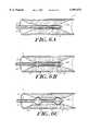
- FIG. 6Aillustrates the distal end of a phototherapeutic apparatus of the present invention inserted into a patient's lumen and deployed in an initial position prior to the fluted region of the sheath contacting the inner surface of the lumen;
- FIG. 6Bis a further illustration of the apparatus of FIG. 6A after initial expansion of the fluted region of the sheath of the apparatus.
- FIG. 6Cfurther illustrates the expansion of the sheath of the phototherapeutic apparatus of FIG. 6A.
- FIGS. 1, 1A, 4 and 5one embodiment of a phototherapeutic apparatus 10 according to the invention is illustrated having a tubular sheath 12 and an inner optically-transmissive fiber element 14.
- this phototherapeutic apparatus 10is shown schematically in operation.
- the diffuser apparatus with its fluted tubular sheathis coupled to a source of phototherapeutic radiation 36, (e.g., a laser) and positioned within a patient's body to provide phototherapy.
- the diffuser assemblycan fit within a standard guiding catheter 32.
- the catheter 32as illustrated in FIG. 4, includes an operating handle 50 with a trigger element 52 connected to the fiber element 14 forming a retractor element.
- the catheterfurther includes electrical sensing elements 34 and/or at least one additional channel 38 for introduction of saline or therapeutic solutions.
- the proximal end of the optically-transmissive fiber element 14is coupled to a source of phototherapeutic radiation 36.
- the distal end of the sheath 12is fluted such that axial compression of the sheath results in expansion of expansion elements 18 in the fluted region 16. This expansion forces the expansion elements into the sides of a body lumen, as can be seen in FIGS. 6A-6C.
- the use of the phototherapeutic apparatus of the present inventionis shown schematically.
- the instrument 10is positioned next to a segment of a patient's lumen where insertion and radiation is desired.
- the apparatusincludes an outer sheath 12 having a flexible fluted region 16 and an inner optically-transmissive fiber element 14 with tip 26.
- the fiber 14 and sheath 12are constructed with sufficient clearance to permit saline or other therapeutic liquids to be released during the procedure.
- saline flushing of the distal end of the optically-transmissive fiber element 14may be desirable to cool the tissue surface proximal to the treatment site.
- FIG. 6Binitial expansion of the sheath 12 is shown.
- the optically-transmissive fiberis inserted into the patient's lumen.
- the fluted region 16is expanded to center the phototherapy device 10 within the patient's lumen.
- the expansion of the fluted regionis accomplished by axial compression of the sheath 12.
- the axial compression of the sheathis accomplished by pulling back on the optically-transmissive fiber element 14.
- the fiber element 14can be connected to the housing 28 and the end cap 26. These elements can be bonded by melting.
- the distal end of the fiber element 14 and the sheath 12can be thermally bonded or assembled.
- an operatorcan cause relative sliding motion of the fiber element 14 and the sheath 12 to axially compress the sheath 12.
- One method of achieving the relative sliding motion and axial compressionis to pull back on the optical fiber element 14 while holding the sheath 12 still.
- the trigger element 52is provided as a convenient means for pulling back on the optical fiber element 14.
- the trigger element 52is coupled to the proximal end of the fiber element 14 and the proximal end of the sheath 12 so that the trigger element can control the expansion of the non-occluding expansion elements 18.
- An alternative method of achieving axial compressionis pushing the sheath 12 forward, while holding the fiber element 14 still.
- the compression of the sheath 12causes the expansion of the flexible fluted region 16, thereby centering the device within the patient's lumen.
- sheath 12has completely expanded in the patient's lumen pushing into the surrounding tissue and centering the phototherapy device 10 in the lumen.
- the fluted regionallows fluids, including gases, to pass the phototherapy device 10 while the device is in operation.
- there is sufficient clearancee.g., about 0.02 mm to about 2 mm, between the optical fiber 20 and the surrounding sheath 12 to facilitate delivery of therapeutic liquids to the radiation site.
- the length of the illustrated expansion elementsare about 1 mm to about 5 cm, and the width of the expansion elements are about 0.2 mm to about 1 cm. This design allows reduction of hematocrit by flushing out the fluted region 16.
- FIGS. 2, 2A, and 2Banother embodiment of a phototherapeutic apparatus includes distinct balloon expansion elements 18.
- the wall of the main artery undergoing treatmentis represented by the numeral 11.
- an operatorinserts the light-emitting portion of the catheter into the diseased blood vessel to a position adjacent the deposit of atheromatous plaque to be lysed.
- the catheterincludes a tube 37 and balloon expansion elements 18 attached to the outside of the distal end of the tube 37.
- the tubecontains an optical fiber 20 and a gas delivery conduit 21.
- the deflated state of the balloon elementsis indicated by the dotted lines 17 in FIG. 2.
- Inflation of the balloon expansion elementsis provided for by the gas delivery conduit 21 which is in fluid communication with the interior of the balloon elements and which can be connected, at its opposite end, to a source of pressurized gas.
- the balloon expansion elementsupon inflation the balloon expansion elements do not occlude flow of air or liquid past the phototherapy treatment site.
- At least one optical fiber 20is provided for transmitting light from an external source to a light-emitting tip 23.
- the balloon expansion elementsare preferably composed of material that transmits the light emitted by the light-emitting tip 23.
- FIGS. 3 and 3AYet another embodiment of a phototherapeutic apparatus according to the invention is shown in FIGS. 3 and 3A.
- Rigid expansion elements 18are extended once the apparatus is inserted in a body lumen for treatment of the lumen.
- the rigid expansion elementsare extended by distal movement of the expansion actuating element 41 relative to the tubular sheath 12. Again the rigid expansion elements 18 do not occlude flow of air or liquid past the phototherapy treatment site.
- FIG. 4is a more detailed cross-sectional view of the distal end of the apparatus of FIG. 1.
- the optically-transmissive elementis shown having an optical fiber 20 with an optically transmissive core 22 surrounded by a cladding, and buffer coating.
- the end face of fiber core 22is inserted into a housing 28 which contains a scattering medium 24 with optional individual scatterer particles 25.
- the medium 24has a greater refractive index than the housing 28.
- an end cap 26can be disposed.
- the end capmay also be fitted with a reflective mirror 40.
- the end capcan further be ground or polished to an atraumatic blunt or rounded end 30.
- At least one dosimetry detector 27is included in an expansion element 18.
- the dosimetry detectoris connected to a control element 29 and is preferably located at the longitudinal midpoint of the expansion element 18.
- Light propagating through the optical fiber core 22is transmitted into the scatterer medium and scattered in a cylindrical pattern along the length of the assembly 14. Each time the light encounters a scatterer particle, it is deflected and, at some point, the net deflection exceeds the critical angle for internal reflection at the interface between the housing 28 and the medium 24. When this happens the light will exit.
- the housingcan either be made sufficiently long to ensure that virtually all of the light entering it is eventually scattered and diffused in a single path, or as noted above, a reflective mirror can be fitted to the distal end of each diffuser assembly. When a mirror is employed, light propagating through the medium 24 will be at least partially scattered before it reaches mirror 40.
- the dosimetry detector 27 and control element 29detect the amount of radiation delivered to the exposure area of the lumen.
- the control element 29can automatically terminate the transmission of phototherapeutic radiation once the amount of radiation delivered reaches a predetermined level or the control element 29 can merely display the amount of radiation delivered to the exposure area.
- An exemplary manufacturing process suitable for joining a diffuser assembly to a glass-clad or polymer-clad optical fiber having an outer diameter of about 50 to about 1000 micrometersincludes stripping off the buffer from the end of the optical fiber, e.g., exposing about two or three millimeters of the inner fiber core and its cladding. (It is not necessary to strip the cladding away from the core.)
- the fiber end facePrior to stripping, the fiber end face preferably should be prepared and polished as known in the art to minimize boundary or interface losses.
- a transparent tubular structure which will form the housing for the scatterer mediumis then slipped over the prepared fiber end and, preferably slid beyond the fiber end.
- the tubingcan be about 100 millimeters long and slid over about 75 millimeters of the fiber, leaving an empty lumen of about 25 millimeters in front of the fiber end face.
- the housingis Teflon® FEP (tetrafluoroethylene) tubing, available, for example, from Zeus Industries (Raritan, N.J.).
- a scatterer-loaded materialsuch as a silicone, epoxy or other polymeric material(if a solid diffuser is desired) or a suitable liquid, such as water or a deuterium oxide solution, containing colloidal scatterer particles, such as silica, alumina, or titania, (if a liquid diffuser is desired).
- a scatterer mediumcan be formulated by mixing 70 parts of clear silicone, MastersilTM Formula 151-Clear (available from Masterbond, Inc. of Hackensack, N.J.) with one part of titania filled silicone, MastersilTM Formula 151-White (also available from Masterbond), and a conventional silicone curing or hardening agent.
- the tube lumenshould be completely filled with the silicone, epoxy or other carrier mixture to avoid entrapment of air bubbles.
- the reflectore.g., an aluminum, gold or other reflector-coated plug
- the reflector at the distal end of the scatterer tubecan be a deposited metal or dielectric coating.
- a room temperature hardening agentis used and the diffuser assembly is simply allowed to solidify overnight.
- the fluted regionis made of white fluoropolymers to further homogenize angular output of the radiation.
- the fluted regioncan also be made radiopaque with barium or bismuth fillers.
- the strutscan be formed by axial slices at various locations on the sheath. For example to construct a four strut fluted region, one would make four longitudinal cuts into the sheath, separated by 90° from each other. The length of the cuts will determine the radial extent of the fluted region.
Landscapes
- Health & Medical Sciences (AREA)
- Engineering & Computer Science (AREA)
- Biomedical Technology (AREA)
- Life Sciences & Earth Sciences (AREA)
- Pathology (AREA)
- Radiology & Medical Imaging (AREA)
- Nuclear Medicine, Radiotherapy & Molecular Imaging (AREA)
- Animal Behavior & Ethology (AREA)
- General Health & Medical Sciences (AREA)
- Public Health (AREA)
- Veterinary Medicine (AREA)
- Biophysics (AREA)
- Radiation-Therapy Devices (AREA)
- Laser Surgery Devices (AREA)
Abstract
Description
Claims (19)
Priority Applications (1)
| Application Number | Priority Date | Filing Date | Title |
|---|---|---|---|
| US08/992,930US5997571A (en) | 1997-12-17 | 1997-12-17 | Non-occluding phototherapy probe stabilizers |
Applications Claiming Priority (1)
| Application Number | Priority Date | Filing Date | Title |
|---|---|---|---|
| US08/992,930US5997571A (en) | 1997-12-17 | 1997-12-17 | Non-occluding phototherapy probe stabilizers |
Publications (1)
| Publication Number | Publication Date |
|---|---|
| US5997571Atrue US5997571A (en) | 1999-12-07 |
Family
ID=25538899
Family Applications (1)
| Application Number | Title | Priority Date | Filing Date |
|---|---|---|---|
| US08/992,930Expired - Fee RelatedUS5997571A (en) | 1997-12-17 | 1997-12-17 | Non-occluding phototherapy probe stabilizers |
Country Status (1)
| Country | Link |
|---|---|
| US (1) | US5997571A (en) |
Cited By (80)
| Publication number | Priority date | Publication date | Assignee | Title |
|---|---|---|---|---|
| US6196996B1 (en)* | 1993-07-15 | 2001-03-06 | Paul S. Teirstein | Irradiation catheter and method of use |
| US6349460B1 (en)* | 1999-01-21 | 2002-02-26 | At&T Corp | Fiber installation method and apparatus |
| US6375654B1 (en) | 2000-05-19 | 2002-04-23 | Cardiofocus, Inc. | Catheter system with working portion radially expandable upon rotation |
| WO2002049524A1 (en)* | 2000-12-18 | 2002-06-27 | Dornier Medtech Holding International Gmbh | Applicator for laser-surgery and a method for the production thereof |
| US6563993B1 (en)* | 1998-08-10 | 2003-05-13 | 3M Innovative Properties Company | Light fiber and a method for producing the same |
| US6699268B2 (en)* | 2000-12-15 | 2004-03-02 | Alsius Corporation | Radio frequency patient heating system |
| US20040092830A1 (en)* | 2002-08-05 | 2004-05-13 | Scott Robert W. | Catheter and method for diagnosis and treatment of diseased vessels |
| US20040204738A1 (en)* | 2003-04-10 | 2004-10-14 | Scimed Life Systems, Inc. | Vessel occluding material extractor |
| US20050096643A1 (en)* | 2003-10-30 | 2005-05-05 | Medical Cv, Inc. | Apparatus and method for laser treatment |
| US20050106710A1 (en)* | 2003-11-14 | 2005-05-19 | Friedman Marc D. | Phototherapy device and system |
| US20050131510A1 (en)* | 2003-03-14 | 2005-06-16 | Chen James C. | Device for distal protection and treatment of blood vessels |
| US20050128742A1 (en)* | 2003-03-14 | 2005-06-16 | Chen James C. | Light generating device that self centers within a lumen to render photodynamic therapy |
| US20050228260A1 (en)* | 2003-03-14 | 2005-10-13 | Phillip Burwell | Light generating device to intravascular use |
| US6962584B1 (en)* | 2001-09-06 | 2005-11-08 | Stone Gregg W | Electromagnetic photonic catheter for reducing restenosis |
| US20060104593A1 (en)* | 2004-11-16 | 2006-05-18 | Biotex, Inc. | Light diffusing tip |
| US20060111762A1 (en)* | 2004-11-20 | 2006-05-25 | Erasmus Medical Centre | Device and method for photodynamic therapy of the nasopharyngeal cavity |
| US20060217693A1 (en)* | 2003-11-07 | 2006-09-28 | Biotex, Inc. | Cooled laser fiber for improved thermal therapy |
| US7131963B1 (en) | 2002-06-27 | 2006-11-07 | Advanced Cardiovascular Systems, Inc. | Catheters and methods of using catheters |
| US20080119694A1 (en)* | 2006-11-17 | 2008-05-22 | Lee James K | Catheter with omni-Directional optical tip having isolated optical paths |
| US20080269846A1 (en)* | 2003-03-14 | 2008-10-30 | Light Sciences Oncology, Inc. | Device for treatment of blood vessels using light |
| US20090005768A1 (en)* | 2006-05-02 | 2009-01-01 | Shiva Sharareh | Catheter with omni-directional optical lesion evaluation |
| US20090131931A1 (en)* | 2007-11-16 | 2009-05-21 | Lee James K | Catheter with omni-directional optical tip having isolated optical paths |
| US20100114081A1 (en)* | 2008-11-05 | 2010-05-06 | Spectranetics | Biasing laser catheter: monorail design |
| US20100145415A1 (en)* | 2006-10-11 | 2010-06-10 | Dahm Jonathan S | Light delivery system |
| US7860556B2 (en) | 2005-02-02 | 2010-12-28 | Voyage Medical, Inc. | Tissue imaging and extraction systems |
| US7860555B2 (en) | 2005-02-02 | 2010-12-28 | Voyage Medical, Inc. | Tissue visualization and manipulation system |
| US20110077464A1 (en)* | 2003-03-14 | 2011-03-31 | Light Sciences Oncology, Inc. | Medical apparatus employing flexible light structures and methods for manufacturing same |
| US7918787B2 (en) | 2005-02-02 | 2011-04-05 | Voyage Medical, Inc. | Tissue visualization and manipulation systems |
| US7930016B1 (en) | 2005-02-02 | 2011-04-19 | Voyage Medical, Inc. | Tissue closure system |
| US8050746B2 (en) | 2005-02-02 | 2011-11-01 | Voyage Medical, Inc. | Tissue visualization device and method variations |
| US8078266B2 (en) | 2005-10-25 | 2011-12-13 | Voyage Medical, Inc. | Flow reduction hood systems |
| US8109981B2 (en) | 2005-01-25 | 2012-02-07 | Valam Corporation | Optical therapies and devices |
| US8131350B2 (en) | 2006-12-21 | 2012-03-06 | Voyage Medical, Inc. | Stabilization of visualization catheters |
| US8137333B2 (en) | 2005-10-25 | 2012-03-20 | Voyage Medical, Inc. | Delivery of biological compounds to ischemic and/or infarcted tissue |
| US8221310B2 (en) | 2005-10-25 | 2012-07-17 | Voyage Medical, Inc. | Tissue visualization device and method variations |
| US8235985B2 (en) | 2007-08-31 | 2012-08-07 | Voyage Medical, Inc. | Visualization and ablation system variations |
| US8333012B2 (en) | 2008-10-10 | 2012-12-18 | Voyage Medical, Inc. | Method of forming electrode placement and connection systems |
| US8657805B2 (en) | 2007-05-08 | 2014-02-25 | Intuitive Surgical Operations, Inc. | Complex shape steerable tissue visualization and manipulation catheter |
| US8694071B2 (en) | 2010-02-12 | 2014-04-08 | Intuitive Surgical Operations, Inc. | Image stabilization techniques and methods |
| US8709008B2 (en) | 2007-05-11 | 2014-04-29 | Intuitive Surgical Operations, Inc. | Visual electrode ablation systems |
| US8758229B2 (en) | 2006-12-21 | 2014-06-24 | Intuitive Surgical Operations, Inc. | Axial visualization systems |
| US20140205498A1 (en)* | 2011-08-16 | 2014-07-24 | Technical University Of Denmark | Liquid filled light distributor and a method of use |
| US8858609B2 (en) | 2008-02-07 | 2014-10-14 | Intuitive Surgical Operations, Inc. | Stent delivery under direct visualization |
| US8876804B2 (en) | 2010-12-17 | 2014-11-04 | Ams Research Corporation | Ablation device |
| US8909316B2 (en) | 2011-05-18 | 2014-12-09 | St. Jude Medical, Cardiology Division, Inc. | Apparatus and method of assessing transvascular denervation |
| US8920413B2 (en)* | 2004-11-12 | 2014-12-30 | Asthmatx, Inc. | Energy delivery devices and methods |
| US8934962B2 (en) | 2005-02-02 | 2015-01-13 | Intuitive Surgical Operations, Inc. | Electrophysiology mapping and visualization system |
| US8936592B2 (en) | 2010-06-03 | 2015-01-20 | Ams Research Corporation | Laser tissue ablation system |
| US9055906B2 (en) | 2006-06-14 | 2015-06-16 | Intuitive Surgical Operations, Inc. | In-vivo visualization systems |
| US9101735B2 (en) | 2008-07-07 | 2015-08-11 | Intuitive Surgical Operations, Inc. | Catheter control systems |
| US9155452B2 (en) | 2007-04-27 | 2015-10-13 | Intuitive Surgical Operations, Inc. | Complex shape steerable tissue visualization and manipulation catheter |
| US9220887B2 (en) | 2011-06-09 | 2015-12-29 | Astora Women's Health LLC | Electrode lead including a deployable tissue anchor |
| US9333031B2 (en) | 2013-04-08 | 2016-05-10 | Apama Medical, Inc. | Visualization inside an expandable medical device |
| US9403029B2 (en) | 2007-07-18 | 2016-08-02 | Visualase, Inc. | Systems and methods for thermal therapy |
| US9468364B2 (en) | 2008-11-14 | 2016-10-18 | Intuitive Surgical Operations, Inc. | Intravascular catheter with hood and image processing systems |
| US9510732B2 (en) | 2005-10-25 | 2016-12-06 | Intuitive Surgical Operations, Inc. | Methods and apparatus for efficient purging |
| USD775728S1 (en) | 2015-07-02 | 2017-01-03 | The Spectranetics Corporation | Medical device handle |
| US9610006B2 (en) | 2008-11-11 | 2017-04-04 | Shifamed Holdings, Llc | Minimally invasive visualization systems |
| US9649159B2 (en) | 2008-12-17 | 2017-05-16 | The Spectranetics Corporation | Eccentric balloon laser catheter |
| US9655677B2 (en) | 2010-05-12 | 2017-05-23 | Shifamed Holdings, Llc | Ablation catheters including a balloon and electrodes |
| US9795442B2 (en) | 2008-11-11 | 2017-10-24 | Shifamed Holdings, Llc | Ablation catheters |
| US9814522B2 (en) | 2010-04-06 | 2017-11-14 | Intuitive Surgical Operations, Inc. | Apparatus and methods for ablation efficacy |
| US9907614B2 (en) | 2014-10-29 | 2018-03-06 | The Spectranetics Corporation | Laser energy delivery devices including laser transmission detection systems and methods |
| US10004388B2 (en) | 2006-09-01 | 2018-06-26 | Intuitive Surgical Operations, Inc. | Coronary sinus cannulation |
| US10064540B2 (en) | 2005-02-02 | 2018-09-04 | Intuitive Surgical Operations, Inc. | Visualization apparatus for transseptal access |
| US10070772B2 (en) | 2006-09-01 | 2018-09-11 | Intuitive Surgical Operations, Inc. | Precision control systems for tissue visualization and manipulation assemblies |
| US10098694B2 (en) | 2013-04-08 | 2018-10-16 | Apama Medical, Inc. | Tissue ablation and monitoring thereof |
| US10111705B2 (en) | 2008-10-10 | 2018-10-30 | Intuitive Surgical Operations, Inc. | Integral electrode placement and connection systems |
| US10307610B2 (en) | 2006-01-18 | 2019-06-04 | Light Sciences Oncology Inc. | Method and apparatus for light-activated drug therapy |
| US10335131B2 (en) | 2006-10-23 | 2019-07-02 | Intuitive Surgical Operations, Inc. | Methods for preventing tissue migration |
| US10349824B2 (en) | 2013-04-08 | 2019-07-16 | Apama Medical, Inc. | Tissue mapping and visualization systems |
| US10376711B2 (en) | 2003-03-14 | 2019-08-13 | Light Sciences Oncology Inc. | Light generating guide wire for intravascular use |
| US10441136B2 (en) | 2006-12-18 | 2019-10-15 | Intuitive Surgical Operations, Inc. | Systems and methods for unobstructed visualization and ablation |
| US10450656B2 (en)* | 2014-02-20 | 2019-10-22 | Biolase, Inc. | Pre-initiated optical fibers and methods of making thereof |
| US10492863B2 (en) | 2014-10-29 | 2019-12-03 | The Spectranetics Corporation | Laser energy delivery devices including laser transmission detection systems and methods |
| US10736693B2 (en) | 2015-11-16 | 2020-08-11 | Apama Medical, Inc. | Energy delivery devices |
| US11172821B2 (en) | 2016-04-28 | 2021-11-16 | Medtronic Navigation, Inc. | Navigation and local thermometry |
| US11406250B2 (en) | 2005-02-02 | 2022-08-09 | Intuitive Surgical Operations, Inc. | Methods and apparatus for treatment of atrial fibrillation |
| US11478152B2 (en) | 2005-02-02 | 2022-10-25 | Intuitive Surgical Operations, Inc. | Electrophysiology mapping and visualization system |
| US20230118963A1 (en)* | 2020-03-06 | 2023-04-20 | Kaneka Corporation | Balloon catheter |
Citations (17)
| Publication number | Priority date | Publication date | Assignee | Title |
|---|---|---|---|---|
| US34544A (en)* | 1862-02-25 | Improvement in running-gear for railroad-cars | ||
| US4336809A (en)* | 1980-03-17 | 1982-06-29 | Burleigh Instruments, Inc. | Human and animal tissue photoradiation system and method |
| US4878492A (en)* | 1987-10-08 | 1989-11-07 | C. R. Bard, Inc. | Laser balloon catheter |
| US4998930A (en)* | 1988-08-03 | 1991-03-12 | Phototherapeutic Systems | Intracavity laser phototherapy method |
| US5053033A (en)* | 1990-10-10 | 1991-10-01 | Boston Advanced Technologies, Inc. | Inhibition of restenosis by ultraviolet radiation |
| US5074871A (en)* | 1989-12-07 | 1991-12-24 | Evi Corporation | Catheter atherotome |
| US5125925A (en)* | 1988-08-03 | 1992-06-30 | Photoradiation Systems | Intracavity laser catheter with sensing fiber |
| US5188602A (en)* | 1990-07-12 | 1993-02-23 | Interventional Thermodynamics, Inc. | Method and device for delivering heat to hollow body organs |
| US5188635A (en)* | 1988-02-08 | 1993-02-23 | Wolfgang Radtke | Catheter for percutaneous surgery of blood vessels and organs using radiant energy |
| USRE34544E (en) | 1982-11-23 | 1994-02-15 | The Beth Israel Hospital Association | Method of treatment of artherosclerosis and balloon catheter the same |
| US5632767A (en)* | 1994-09-09 | 1997-05-27 | Rare Earth Medical, Inc. | Loop diffusers for diffusion of optical radiation |
| US5637877A (en)* | 1995-06-06 | 1997-06-10 | Rare Earth Medical, Inc. | Ultraviolet sterilization of instrument lumens |
| US5643253A (en)* | 1995-06-06 | 1997-07-01 | Rare Earth Medical, Inc. | Phototherapy apparatus with integral stopper device |
| US5649978A (en)* | 1993-05-11 | 1997-07-22 | Target Therapeutics, Inc. | Temporary inflatable intravascular prosthesis |
| US5700243A (en)* | 1992-10-30 | 1997-12-23 | Pdt Systems, Inc. | Balloon perfusion catheter |
| US5824005A (en)* | 1995-08-22 | 1998-10-20 | Board Of Regents, The University Of Texas System | Maneuverable electrophysiology catheter for percutaneous or intraoperative ablation of cardiac arrhythmias |
| US5855565A (en)* | 1997-02-21 | 1999-01-05 | Bar-Cohen; Yaniv | Cardiovascular mechanically expanding catheter |
- 1997
- 1997-12-17USUS08/992,930patent/US5997571A/ennot_activeExpired - Fee Related
Patent Citations (17)
| Publication number | Priority date | Publication date | Assignee | Title |
|---|---|---|---|---|
| US34544A (en)* | 1862-02-25 | Improvement in running-gear for railroad-cars | ||
| US4336809A (en)* | 1980-03-17 | 1982-06-29 | Burleigh Instruments, Inc. | Human and animal tissue photoradiation system and method |
| USRE34544E (en) | 1982-11-23 | 1994-02-15 | The Beth Israel Hospital Association | Method of treatment of artherosclerosis and balloon catheter the same |
| US4878492A (en)* | 1987-10-08 | 1989-11-07 | C. R. Bard, Inc. | Laser balloon catheter |
| US5188635A (en)* | 1988-02-08 | 1993-02-23 | Wolfgang Radtke | Catheter for percutaneous surgery of blood vessels and organs using radiant energy |
| US4998930A (en)* | 1988-08-03 | 1991-03-12 | Phototherapeutic Systems | Intracavity laser phototherapy method |
| US5125925A (en)* | 1988-08-03 | 1992-06-30 | Photoradiation Systems | Intracavity laser catheter with sensing fiber |
| US5074871A (en)* | 1989-12-07 | 1991-12-24 | Evi Corporation | Catheter atherotome |
| US5188602A (en)* | 1990-07-12 | 1993-02-23 | Interventional Thermodynamics, Inc. | Method and device for delivering heat to hollow body organs |
| US5053033A (en)* | 1990-10-10 | 1991-10-01 | Boston Advanced Technologies, Inc. | Inhibition of restenosis by ultraviolet radiation |
| US5700243A (en)* | 1992-10-30 | 1997-12-23 | Pdt Systems, Inc. | Balloon perfusion catheter |
| US5649978A (en)* | 1993-05-11 | 1997-07-22 | Target Therapeutics, Inc. | Temporary inflatable intravascular prosthesis |
| US5632767A (en)* | 1994-09-09 | 1997-05-27 | Rare Earth Medical, Inc. | Loop diffusers for diffusion of optical radiation |
| US5637877A (en)* | 1995-06-06 | 1997-06-10 | Rare Earth Medical, Inc. | Ultraviolet sterilization of instrument lumens |
| US5643253A (en)* | 1995-06-06 | 1997-07-01 | Rare Earth Medical, Inc. | Phototherapy apparatus with integral stopper device |
| US5824005A (en)* | 1995-08-22 | 1998-10-20 | Board Of Regents, The University Of Texas System | Maneuverable electrophysiology catheter for percutaneous or intraoperative ablation of cardiac arrhythmias |
| US5855565A (en)* | 1997-02-21 | 1999-01-05 | Bar-Cohen; Yaniv | Cardiovascular mechanically expanding catheter |
Cited By (176)
| Publication number | Priority date | Publication date | Assignee | Title |
|---|---|---|---|---|
| US6585715B1 (en) | 1993-07-15 | 2003-07-01 | Paul S. Teirstein | Irradiation catheter and method of use |
| US6196996B1 (en)* | 1993-07-15 | 2001-03-06 | Paul S. Teirstein | Irradiation catheter and method of use |
| US6563993B1 (en)* | 1998-08-10 | 2003-05-13 | 3M Innovative Properties Company | Light fiber and a method for producing the same |
| US6349460B1 (en)* | 1999-01-21 | 2002-02-26 | At&T Corp | Fiber installation method and apparatus |
| US6375654B1 (en) | 2000-05-19 | 2002-04-23 | Cardiofocus, Inc. | Catheter system with working portion radially expandable upon rotation |
| US6699268B2 (en)* | 2000-12-15 | 2004-03-02 | Alsius Corporation | Radio frequency patient heating system |
| WO2002049524A1 (en)* | 2000-12-18 | 2002-06-27 | Dornier Medtech Holding International Gmbh | Applicator for laser-surgery and a method for the production thereof |
| US6962584B1 (en)* | 2001-09-06 | 2005-11-08 | Stone Gregg W | Electromagnetic photonic catheter for reducing restenosis |
| US20070088317A1 (en)* | 2002-06-27 | 2007-04-19 | Hyde Gregory M | Catheters and methods of using catheters |
| US7131963B1 (en) | 2002-06-27 | 2006-11-07 | Advanced Cardiovascular Systems, Inc. | Catheters and methods of using catheters |
| US20040092830A1 (en)* | 2002-08-05 | 2004-05-13 | Scott Robert W. | Catheter and method for diagnosis and treatment of diseased vessels |
| US20050131510A1 (en)* | 2003-03-14 | 2005-06-16 | Chen James C. | Device for distal protection and treatment of blood vessels |
| US8685071B2 (en) | 2003-03-14 | 2014-04-01 | Purdue Pharmaceutical Products L.P. | Medical apparatus employing flexible light structures |
| US20110077464A1 (en)* | 2003-03-14 | 2011-03-31 | Light Sciences Oncology, Inc. | Medical apparatus employing flexible light structures and methods for manufacturing same |
| US20050128742A1 (en)* | 2003-03-14 | 2005-06-16 | Chen James C. | Light generating device that self centers within a lumen to render photodynamic therapy |
| US20080269846A1 (en)* | 2003-03-14 | 2008-10-30 | Light Sciences Oncology, Inc. | Device for treatment of blood vessels using light |
| US20080027517A1 (en)* | 2003-03-14 | 2008-01-31 | Light Sciences Oncology, Inc. | Light generating device for intravascular use |
| US20050228260A1 (en)* | 2003-03-14 | 2005-10-13 | Phillip Burwell | Light generating device to intravascular use |
| US7252677B2 (en) | 2003-03-14 | 2007-08-07 | Light Sciences Oncology, Inc. | Light generating device to intravascular use |
| US7730894B2 (en) | 2003-03-14 | 2010-06-08 | Light Sciences Oncology, Inc. | Photodynamic therapy apparatus and method for vascular tissue treatment |
| US10376711B2 (en) | 2003-03-14 | 2019-08-13 | Light Sciences Oncology Inc. | Light generating guide wire for intravascular use |
| US8728106B2 (en) | 2003-04-10 | 2014-05-20 | Boston Scientific Scimed, Inc. | Vessel occluding material extractor |
| US8070761B2 (en) | 2003-04-10 | 2011-12-06 | Boston Scientific Scimed, Inc. | Vessel occluding material extractor |
| US20040204738A1 (en)* | 2003-04-10 | 2004-10-14 | Scimed Life Systems, Inc. | Vessel occluding material extractor |
| WO2005004704A3 (en)* | 2003-07-08 | 2005-11-03 | Light Sciences Corp | Light generating device that self centers within a lumen to render photodynamic therapy |
| US7267674B2 (en)* | 2003-10-30 | 2007-09-11 | Medical Cv, Inc. | Apparatus and method for laser treatment |
| US20050159734A1 (en)* | 2003-10-30 | 2005-07-21 | Medical Cv, Inc. | Atraumatic laser tip for atrial fibrillation treatment |
| US7163534B2 (en)* | 2003-10-30 | 2007-01-16 | Medical Cv, Inc. | Laser-based maze procedure for atrial fibrillation |
| US7169142B2 (en)* | 2003-10-30 | 2007-01-30 | Medical Cv, Inc. | Malleable energy wand for maze procedure |
| US20050096643A1 (en)* | 2003-10-30 | 2005-05-05 | Medical Cv, Inc. | Apparatus and method for laser treatment |
| US20050143722A1 (en)* | 2003-10-30 | 2005-06-30 | Medical Cv, Inc. | Laser-based maze procedure for atrial fibrillation |
| US7137977B2 (en)* | 2003-10-30 | 2006-11-21 | Medical Cv, Inc. | Atraumatic laser tip for atrial fibrillation treatment |
| US20060217693A1 (en)* | 2003-11-07 | 2006-09-28 | Biotex, Inc. | Cooled laser fiber for improved thermal therapy |
| US10869721B2 (en) | 2003-11-07 | 2020-12-22 | Visualase, Inc. | Cooled laser fiber and method for improved thermal therapy |
| US7270656B2 (en) | 2003-11-07 | 2007-09-18 | Visualase, Inc. | Cooled laser fiber for improved thermal therapy |
| US20070219544A1 (en)* | 2003-11-07 | 2007-09-20 | Visualase, Inc. | Cooled laser fiber for improved thermal therapy |
| US9339336B2 (en) | 2003-11-07 | 2016-05-17 | Visualase, Inc. | Cooled laser fiber and method for improved thermal therapy |
| US8851080B2 (en) | 2003-11-07 | 2014-10-07 | Visualase, Inc. | Thermal therapy apparatus and method for delivering energy to a tissue using a cooled laser fiber |
| US8211095B2 (en) | 2003-11-07 | 2012-07-03 | Visualase, Inc. | Cooled laser fiber for improved thermal therapy |
| US7261730B2 (en) | 2003-11-14 | 2007-08-28 | Lumerx, Inc. | Phototherapy device and system |
| US20070123957A1 (en)* | 2003-11-14 | 2007-05-31 | Lumerx, Inc. | Flexible array |
| US7449026B2 (en) | 2003-11-14 | 2008-11-11 | Lumerx, Inc. | Intra-cavity catheters and methods of use |
| US20050131500A1 (en)* | 2003-11-14 | 2005-06-16 | Zalesky Paul J. | Intra-cavity catheters and methods of use |
| US20050104059A1 (en)* | 2003-11-14 | 2005-05-19 | Friedman Marc D. | Flexible array |
| US20050106710A1 (en)* | 2003-11-14 | 2005-05-19 | Friedman Marc D. | Phototherapy device and system |
| US7135034B2 (en) | 2003-11-14 | 2006-11-14 | Lumerx, Inc. | Flexible array |
| US8920413B2 (en)* | 2004-11-12 | 2014-12-30 | Asthmatx, Inc. | Energy delivery devices and methods |
| US20080015560A1 (en)* | 2004-11-16 | 2008-01-17 | Biotex, Inc. | Light diffusing tip |
| US20060104593A1 (en)* | 2004-11-16 | 2006-05-18 | Biotex, Inc. | Light diffusing tip |
| US7274847B2 (en) | 2004-11-16 | 2007-09-25 | Biotex, Inc. | Light diffusing tip |
| US7412141B2 (en) | 2004-11-16 | 2008-08-12 | Biotex, Inc. | Light diffusing tip |
| US7763058B2 (en) | 2004-11-20 | 2010-07-27 | Dick Sterenborg | Device and method for photodynamic therapy of the nasopharyngeal cavity |
| US20060111762A1 (en)* | 2004-11-20 | 2006-05-25 | Erasmus Medical Centre | Device and method for photodynamic therapy of the nasopharyngeal cavity |
| WO2006054179A1 (en) | 2004-11-20 | 2006-05-26 | Erasmus University Medical Center Rotterdam | Device and method for photodynamic therapy of the nasopharyngeal cavity |
| US8109981B2 (en) | 2005-01-25 | 2012-02-07 | Valam Corporation | Optical therapies and devices |
| US12408824B2 (en) | 2005-02-02 | 2025-09-09 | Intuitive Surgical Operations, Inc. | Tissue visualization and manipulation system |
| US7918787B2 (en) | 2005-02-02 | 2011-04-05 | Voyage Medical, Inc. | Tissue visualization and manipulation systems |
| US8050746B2 (en) | 2005-02-02 | 2011-11-01 | Voyage Medical, Inc. | Tissue visualization device and method variations |
| US10463237B2 (en) | 2005-02-02 | 2019-11-05 | Intuitive Surgical Operations, Inc. | Delivery of biological compounds to ischemic and/or infarcted tissue |
| US9526401B2 (en) | 2005-02-02 | 2016-12-27 | Intuitive Surgical Operations, Inc. | Flow reduction hood systems |
| US7930016B1 (en) | 2005-02-02 | 2011-04-19 | Voyage Medical, Inc. | Tissue closure system |
| US10772492B2 (en) | 2005-02-02 | 2020-09-15 | Intuitive Surgical Operations, Inc. | Methods and apparatus for efficient purging |
| US12329360B2 (en) | 2005-02-02 | 2025-06-17 | Intuitive Surgical Operations, Inc. | Methods and apparatus for treatment of atrial fibrillation |
| US10278588B2 (en) | 2005-02-02 | 2019-05-07 | Intuitive Surgical Operations, Inc. | Electrophysiology mapping and visualization system |
| US8417321B2 (en) | 2005-02-02 | 2013-04-09 | Voyage Medical, Inc | Flow reduction hood systems |
| US8419613B2 (en) | 2005-02-02 | 2013-04-16 | Voyage Medical, Inc. | Tissue visualization device |
| US10064540B2 (en) | 2005-02-02 | 2018-09-04 | Intuitive Surgical Operations, Inc. | Visualization apparatus for transseptal access |
| US9332893B2 (en) | 2005-02-02 | 2016-05-10 | Intuitive Surgical Operations, Inc. | Delivery of biological compounds to ischemic and/or infarcted tissue |
| US11406250B2 (en) | 2005-02-02 | 2022-08-09 | Intuitive Surgical Operations, Inc. | Methods and apparatus for treatment of atrial fibrillation |
| US10368729B2 (en) | 2005-02-02 | 2019-08-06 | Intuitive Surgical Operations, Inc. | Methods and apparatus for efficient purging |
| US11478152B2 (en) | 2005-02-02 | 2022-10-25 | Intuitive Surgical Operations, Inc. | Electrophysiology mapping and visualization system |
| US11889982B2 (en) | 2005-02-02 | 2024-02-06 | Intuitive Surgical Operations, Inc. | Electrophysiology mapping and visualization system |
| US8934962B2 (en) | 2005-02-02 | 2015-01-13 | Intuitive Surgical Operations, Inc. | Electrophysiology mapping and visualization system |
| US7860555B2 (en) | 2005-02-02 | 2010-12-28 | Voyage Medical, Inc. | Tissue visualization and manipulation system |
| US7860556B2 (en) | 2005-02-02 | 2010-12-28 | Voyage Medical, Inc. | Tissue imaging and extraction systems |
| US11819190B2 (en) | 2005-02-02 | 2023-11-21 | Intuitive Surgical Operations, Inc. | Methods and apparatus for efficient purging |
| US8814845B2 (en) | 2005-02-02 | 2014-08-26 | Intuitive Surgical Operations, Inc. | Delivery of biological compounds to ischemic and/or infarcted tissue |
| US8137333B2 (en) | 2005-10-25 | 2012-03-20 | Voyage Medical, Inc. | Delivery of biological compounds to ischemic and/or infarcted tissue |
| US8078266B2 (en) | 2005-10-25 | 2011-12-13 | Voyage Medical, Inc. | Flow reduction hood systems |
| US9510732B2 (en) | 2005-10-25 | 2016-12-06 | Intuitive Surgical Operations, Inc. | Methods and apparatus for efficient purging |
| US9192287B2 (en) | 2005-10-25 | 2015-11-24 | Intuitive Surgical Operations, Inc. | Tissue visualization device and method variations |
| US8221310B2 (en) | 2005-10-25 | 2012-07-17 | Voyage Medical, Inc. | Tissue visualization device and method variations |
| US10307610B2 (en) | 2006-01-18 | 2019-06-04 | Light Sciences Oncology Inc. | Method and apparatus for light-activated drug therapy |
| US20090005768A1 (en)* | 2006-05-02 | 2009-01-01 | Shiva Sharareh | Catheter with omni-directional optical lesion evaluation |
| US9149330B2 (en) | 2006-05-02 | 2015-10-06 | Biosense Webster, Inc. | Catheter with omni-directional optical lesion evaluation |
| US9561074B2 (en) | 2006-05-02 | 2017-02-07 | Biosense Webster, Inc. | Catheter with omni-directional optical lesion evaluation |
| US8628520B2 (en) | 2006-05-02 | 2014-01-14 | Biosense Webster, Inc. | Catheter with omni-directional optical lesion evaluation |
| US12376735B2 (en) | 2006-06-14 | 2025-08-05 | Intuitive Surgical Operations, Inc. | In-vivo visualization systems |
| US9055906B2 (en) | 2006-06-14 | 2015-06-16 | Intuitive Surgical Operations, Inc. | In-vivo visualization systems |
| US11882996B2 (en) | 2006-06-14 | 2024-01-30 | Intuitive Surgical Operations, Inc. | In-vivo visualization systems |
| US10470643B2 (en) | 2006-06-14 | 2019-11-12 | Intuitive Surgical Operations, Inc. | In-vivo visualization systems |
| US10004388B2 (en) | 2006-09-01 | 2018-06-26 | Intuitive Surgical Operations, Inc. | Coronary sinus cannulation |
| US10070772B2 (en) | 2006-09-01 | 2018-09-11 | Intuitive Surgical Operations, Inc. | Precision control systems for tissue visualization and manipulation assemblies |
| US11779195B2 (en) | 2006-09-01 | 2023-10-10 | Intuitive Surgical Operations, Inc. | Precision control systems for tissue visualization and manipulation assemblies |
| US11337594B2 (en) | 2006-09-01 | 2022-05-24 | Intuitive Surgical Operations, Inc. | Coronary sinus cannulation |
| USRE46504E1 (en) | 2006-10-11 | 2017-08-08 | Purdue Pharmaceutical Products L.P. | Light delivery system |
| US20100145415A1 (en)* | 2006-10-11 | 2010-06-10 | Dahm Jonathan S | Light delivery system |
| US8685005B2 (en) | 2006-10-11 | 2014-04-01 | Purdue Pharmaceutical Products L.P. | Light delivery system |
| US10335131B2 (en) | 2006-10-23 | 2019-07-02 | Intuitive Surgical Operations, Inc. | Methods for preventing tissue migration |
| US11369356B2 (en) | 2006-10-23 | 2022-06-28 | Intuitive Surgical Operations, Inc. | Methods and apparatus for preventing tissue migration |
| US10813690B2 (en) | 2006-11-17 | 2020-10-27 | Biosense Webster, Inc. | Catheter with omni-directional optical tip having isolated optical paths |
| US20080119694A1 (en)* | 2006-11-17 | 2008-05-22 | Lee James K | Catheter with omni-Directional optical tip having isolated optical paths |
| US10265123B2 (en) | 2006-11-17 | 2019-04-23 | Biosense Webster, Inc. | Catheter with omni-directional optical tip having isolated optical paths |
| US9554708B2 (en) | 2006-11-17 | 2017-01-31 | Biosense Webster, Inc. | Catheter with omni-directional optical tip having isolated optical paths |
| US8986298B2 (en) | 2006-11-17 | 2015-03-24 | Biosense Webster, Inc. | Catheter with omni-directional optical tip having isolated optical paths |
| US10441136B2 (en) | 2006-12-18 | 2019-10-15 | Intuitive Surgical Operations, Inc. | Systems and methods for unobstructed visualization and ablation |
| US8758229B2 (en) | 2006-12-21 | 2014-06-24 | Intuitive Surgical Operations, Inc. | Axial visualization systems |
| US10390685B2 (en) | 2006-12-21 | 2019-08-27 | Intuitive Surgical Operations, Inc. | Off-axis visualization systems |
| US8131350B2 (en) | 2006-12-21 | 2012-03-06 | Voyage Medical, Inc. | Stabilization of visualization catheters |
| US9226648B2 (en) | 2006-12-21 | 2016-01-05 | Intuitive Surgical Operations, Inc. | Off-axis visualization systems |
| US11559188B2 (en) | 2006-12-21 | 2023-01-24 | Intuitive Surgical Operations, Inc. | Off-axis visualization systems |
| US12133631B2 (en) | 2006-12-21 | 2024-11-05 | Intuitive Surgical Operations, Inc. | Off-axis visualization systems |
| US9155452B2 (en) | 2007-04-27 | 2015-10-13 | Intuitive Surgical Operations, Inc. | Complex shape steerable tissue visualization and manipulation catheter |
| US12193638B2 (en) | 2007-04-27 | 2025-01-14 | Intuitive Surgical Operations, Inc. | Complex shape steerable tissue visualization and manipulation catheter |
| US8657805B2 (en) | 2007-05-08 | 2014-02-25 | Intuitive Surgical Operations, Inc. | Complex shape steerable tissue visualization and manipulation catheter |
| US10092172B2 (en) | 2007-05-08 | 2018-10-09 | Intuitive Surgical Operations, Inc. | Complex shape steerable tissue visualization and manipulation catheter |
| US9155587B2 (en) | 2007-05-11 | 2015-10-13 | Intuitive Surgical Operations, Inc. | Visual electrode ablation systems |
| US10624695B2 (en) | 2007-05-11 | 2020-04-21 | Intuitive Surgical Operations, Inc. | Visual electrode ablation systems |
| US8709008B2 (en) | 2007-05-11 | 2014-04-29 | Intuitive Surgical Operations, Inc. | Visual electrode ablation systems |
| US10433909B2 (en) | 2007-07-18 | 2019-10-08 | Visualase, Inc. | Systems and methods for thermal therapy |
| US9403029B2 (en) | 2007-07-18 | 2016-08-02 | Visualase, Inc. | Systems and methods for thermal therapy |
| US11583338B2 (en) | 2007-07-18 | 2023-02-21 | Visualase, Inc. | Systems and methods for thermal therapy |
| US8235985B2 (en) | 2007-08-31 | 2012-08-07 | Voyage Medical, Inc. | Visualization and ablation system variations |
| US20090131931A1 (en)* | 2007-11-16 | 2009-05-21 | Lee James K | Catheter with omni-directional optical tip having isolated optical paths |
| US8500730B2 (en) | 2007-11-16 | 2013-08-06 | Biosense Webster, Inc. | Catheter with omni-directional optical tip having isolated optical paths |
| US10278849B2 (en) | 2008-02-07 | 2019-05-07 | Intuitive Surgical Operations, Inc. | Stent delivery under direct visualization |
| US11241325B2 (en) | 2008-02-07 | 2022-02-08 | Intuitive Surgical Operations, Inc. | Stent delivery under direct visualization |
| US11986409B2 (en) | 2008-02-07 | 2024-05-21 | Intuitive Surgical Operations, Inc. | Stent delivery under direct visualization |
| US8858609B2 (en) | 2008-02-07 | 2014-10-14 | Intuitive Surgical Operations, Inc. | Stent delivery under direct visualization |
| US11350815B2 (en) | 2008-07-07 | 2022-06-07 | Intuitive Surgical Operations, Inc. | Catheter control systems |
| US9101735B2 (en) | 2008-07-07 | 2015-08-11 | Intuitive Surgical Operations, Inc. | Catheter control systems |
| US8333012B2 (en) | 2008-10-10 | 2012-12-18 | Voyage Medical, Inc. | Method of forming electrode placement and connection systems |
| US10111705B2 (en) | 2008-10-10 | 2018-10-30 | Intuitive Surgical Operations, Inc. | Integral electrode placement and connection systems |
| US11950838B2 (en) | 2008-10-10 | 2024-04-09 | Intuitive Surgical Operations, Inc. | Integral electrode placement and connection systems |
| US20100114081A1 (en)* | 2008-11-05 | 2010-05-06 | Spectranetics | Biasing laser catheter: monorail design |
| US9795442B2 (en) | 2008-11-11 | 2017-10-24 | Shifamed Holdings, Llc | Ablation catheters |
| US11744639B2 (en) | 2008-11-11 | 2023-09-05 | Shifamed Holdings Llc | Ablation catheters |
| US9610006B2 (en) | 2008-11-11 | 2017-04-04 | Shifamed Holdings, Llc | Minimally invasive visualization systems |
| US9717557B2 (en) | 2008-11-11 | 2017-08-01 | Apama Medical, Inc. | Cardiac ablation catheters and methods of use thereof |
| US10251700B2 (en) | 2008-11-11 | 2019-04-09 | Shifamed Holdings, Llc | Ablation catheters |
| US11622689B2 (en) | 2008-11-14 | 2023-04-11 | Intuitive Surgical Operations, Inc. | Mapping and real-time imaging a plurality of ablation lesions with registered ablation parameters received from treatment device |
| US9468364B2 (en) | 2008-11-14 | 2016-10-18 | Intuitive Surgical Operations, Inc. | Intravascular catheter with hood and image processing systems |
| US12433490B2 (en) | 2008-11-14 | 2025-10-07 | Intuitive Surgical Operations, Inc. | Ablation and imaging catheter with user interface to catalogue ablation parameters and identification labels for lesions |
| US9649159B2 (en) | 2008-12-17 | 2017-05-16 | The Spectranetics Corporation | Eccentric balloon laser catheter |
| US9907615B2 (en) | 2008-12-17 | 2018-03-06 | The Spectranetics Corporation | Eccentric balloon laser catheter |
| US8694071B2 (en) | 2010-02-12 | 2014-04-08 | Intuitive Surgical Operations, Inc. | Image stabilization techniques and methods |
| US9814522B2 (en) | 2010-04-06 | 2017-11-14 | Intuitive Surgical Operations, Inc. | Apparatus and methods for ablation efficacy |
| US9655677B2 (en) | 2010-05-12 | 2017-05-23 | Shifamed Holdings, Llc | Ablation catheters including a balloon and electrodes |
| US8936592B2 (en) | 2010-06-03 | 2015-01-20 | Ams Research Corporation | Laser tissue ablation system |
| US10105184B2 (en) | 2010-06-03 | 2018-10-23 | Boston Scientific Scimed, Inc. | Laser tissue ablation system |
| US9433467B2 (en) | 2010-06-03 | 2016-09-06 | Boston Scientific Scimed, Inc. | Laser tissue ablation system |
| US8876804B2 (en) | 2010-12-17 | 2014-11-04 | Ams Research Corporation | Ablation device |
| US11751941B2 (en) | 2011-05-18 | 2023-09-12 | St. Jude Medical, Inc. | Apparatus and method of assessing transvascular denervation |
| US10179026B2 (en) | 2011-05-18 | 2019-01-15 | St. Jude Medical, Inc. | Apparatus and method of assessing transvascular denervation |
| US8909316B2 (en) | 2011-05-18 | 2014-12-09 | St. Jude Medical, Cardiology Division, Inc. | Apparatus and method of assessing transvascular denervation |
| US11241280B2 (en) | 2011-05-18 | 2022-02-08 | St. Jude Medical, Inc. | Apparatus and method of assessing transvascular denervation |
| US9220887B2 (en) | 2011-06-09 | 2015-12-29 | Astora Women's Health LLC | Electrode lead including a deployable tissue anchor |
| US10967080B2 (en)* | 2011-08-16 | 2021-04-06 | Uv Clinical Aps | Liquid filled light distributor and a method of use |
| US20140205498A1 (en)* | 2011-08-16 | 2014-07-24 | Technical University Of Denmark | Liquid filled light distributor and a method of use |
| US12076451B2 (en) | 2011-08-16 | 2024-09-03 | Uv Clinical A/S | Liquid filled light distributor and a method of use |
| US10098694B2 (en) | 2013-04-08 | 2018-10-16 | Apama Medical, Inc. | Tissue ablation and monitoring thereof |
| US10349824B2 (en) | 2013-04-08 | 2019-07-16 | Apama Medical, Inc. | Tissue mapping and visualization systems |
| US9333031B2 (en) | 2013-04-08 | 2016-05-10 | Apama Medical, Inc. | Visualization inside an expandable medical device |
| US11439298B2 (en) | 2013-04-08 | 2022-09-13 | Boston Scientific Scimed, Inc. | Surface mapping and visualizing ablation system |
| US11684415B2 (en) | 2013-04-08 | 2023-06-27 | Boston Scientific Scimed, Inc. | Tissue ablation and monitoring thereof |
| US12392039B2 (en) | 2014-02-20 | 2025-08-19 | Biolase Mg Llc | Pre-initiated optical fibers and methods of making thereof |
| US11193209B2 (en) | 2014-02-20 | 2021-12-07 | Biolase, Inc. | Pre-initiated optical fibers and methods of making thereof |
| US10450656B2 (en)* | 2014-02-20 | 2019-10-22 | Biolase, Inc. | Pre-initiated optical fibers and methods of making thereof |
| US10517673B2 (en) | 2014-10-29 | 2019-12-31 | The Spectranetics Corporation | Laser energy delivery devices including laser transmission detection systems and methods |
| US10492863B2 (en) | 2014-10-29 | 2019-12-03 | The Spectranetics Corporation | Laser energy delivery devices including laser transmission detection systems and methods |
| US9907614B2 (en) | 2014-10-29 | 2018-03-06 | The Spectranetics Corporation | Laser energy delivery devices including laser transmission detection systems and methods |
| USD775728S1 (en) | 2015-07-02 | 2017-01-03 | The Spectranetics Corporation | Medical device handle |
| US10736693B2 (en) | 2015-11-16 | 2020-08-11 | Apama Medical, Inc. | Energy delivery devices |
| US12193783B2 (en) | 2016-04-28 | 2025-01-14 | Medtronic Navigation, Inc. | Navigation and local thermometry |
| US11172821B2 (en) | 2016-04-28 | 2021-11-16 | Medtronic Navigation, Inc. | Navigation and local thermometry |
| US20230118963A1 (en)* | 2020-03-06 | 2023-04-20 | Kaneka Corporation | Balloon catheter |
Similar Documents
| Publication | Publication Date | Title |
|---|---|---|
| US5997571A (en) | Non-occluding phototherapy probe stabilizers | |
| US5643253A (en) | Phototherapy apparatus with integral stopper device | |
| US6168591B1 (en) | Guide for penetrating phototherapy | |
| US5632767A (en) | Loop diffusers for diffusion of optical radiation | |
| CA2199384C (en) | Phototherapeutic apparatus | |
| US6270492B1 (en) | Phototherapeutic apparatus with diffusive tip assembly | |
| US5908415A (en) | Phototherapy methods and apparatus | |
| US5637877A (en) | Ultraviolet sterilization of instrument lumens | |
| US5415655A (en) | Medical device including light energy emitting contact tip with means for raising temperature of the tip | |
| US5344419A (en) | Apparatus and method for making a diffusing tip in a balloon catheter system | |
| US5947959A (en) | Phototherapeutic apparatus with diffusive tip assembly | |
| US5169395A (en) | Laser delivery system | |
| CA1319399C (en) | Laser balloon catheter | |
| EP0902653B1 (en) | Balloon catheter for photodynamic therapy | |
| CA1303681C (en) | Wire guided laser catheter | |
| US20050165462A1 (en) | Light delivery device using conical diffusing system and method of forming same | |
| KR20000015834A (en) | Improved phototherapeutic methods and devices for irradiating columnar environments | |
| JP2005534409A (en) | Light transmission catheter | |
| GB2208805A (en) | Laser catheter | |
| AU2249992A (en) | Cylindrical diffusion tips for optical fibers and method for making | |
| US7214223B2 (en) | Photoatherolytic catheter apparatus and method | |
| JP7690460B2 (en) | treatment equipment | |
| EP1527798A2 (en) | Diffusive tip assembly | |
| AU5195700A (en) | Phototherapeutic apparatus | |
| JPH11188099A (en) | Balloon catheter |
Legal Events
| Date | Code | Title | Description |
|---|---|---|---|
| AS | Assignment | Owner name:RARE EARTH MEDICAL, INC., MASSACHUSETTS Free format text:ASSIGNMENT OF ASSIGNORS INTEREST;ASSIGNORS:BAXTER, LINCOLN S.;FARR, NORMAN;SINOFSKY, EDWARD I.;REEL/FRAME:008941/0800 Effective date:19971216 | |
| FEPP | Fee payment procedure | Free format text:PAYOR NUMBER ASSIGNED (ORIGINAL EVENT CODE: ASPN); ENTITY STATUS OF PATENT OWNER: LARGE ENTITY | |
| AS | Assignment | Owner name:CARDIOFOCUS, INC., MASSACHUSETTS Free format text:CHANGE OF NAME;ASSIGNOR:RARE EARTH MEDICAL, INC.;REEL/FRAME:010822/0136 Effective date:19990305 Owner name:CARDIOFOCUS, INC., MASSACHUSETTS Free format text:ASSIGNMENT OF ASSIGNORS INTEREST;ASSIGNOR:CARDIOFOCUS, INC.;REEL/FRAME:010822/0143 Effective date:19990618 | |
| AS | Assignment | Owner name:SILICON VALLEY BANK DBA SILICON VALLEY EAST, CALIF Free format text:SECURITY AGREEMENT;ASSIGNOR:CARDIOFOCUS,INC.;REEL/FRAME:013211/0256 Effective date:20021015 | |
| FEPP | Fee payment procedure | Free format text:PAT HOLDER NO LONGER CLAIMS SMALL ENTITY STATUS, ENTITY STATUS SET TO UNDISCOUNTED (ORIGINAL EVENT CODE: STOL); ENTITY STATUS OF PATENT OWNER: LARGE ENTITY | |
| REFU | Refund | Free format text:REFUND - SURCHARGE FOR LATE PAYMENT, SMALL ENTITY (ORIGINAL EVENT CODE: R2554); ENTITY STATUS OF PATENT OWNER: LARGE ENTITY Free format text:REFUND - SURCHARGE, PETITION TO ACCEPT PYMT AFTER EXP, UNINTENTIONAL (ORIGINAL EVENT CODE: R2551); ENTITY STATUS OF PATENT OWNER: LARGE ENTITY | |
| FPAY | Fee payment | Year of fee payment:4 | |
| SULP | Surcharge for late payment | ||
| AS | Assignment | Owner name:VENTURE LENDING & LEASING IV, INC., CALIFORNIA Free format text:SECURITY INTEREST;ASSIGNOR:CARDIOFOCUS, INC.;REEL/FRAME:016547/0536 Effective date:20050415 | |
| AS | Assignment | Owner name:CARDIOFOCUS, INC., MASSACHUSETTS Free format text:RELEASE;ASSIGNOR:SILICON VALLEY BANK;REEL/FRAME:016610/0594 Effective date:20050406 | |
| AS | Assignment | Owner name:VENTURE LENDING & LEASING IV, INC., CALIFORNIA Free format text:RELEASE;ASSIGNOR:CARDIOFOCUS, INC.;REEL/FRAME:018720/0784 Effective date:20061109 | |
| REMI | Maintenance fee reminder mailed | ||
| LAPS | Lapse for failure to pay maintenance fees | ||
| STCH | Information on status: patent discontinuation | Free format text:PATENT EXPIRED DUE TO NONPAYMENT OF MAINTENANCE FEES UNDER 37 CFR 1.362 | |
| FP | Lapsed due to failure to pay maintenance fee | Effective date:20071207 |