US5997560A - Surgical cutting instrument - Google Patents
Surgical cutting instrumentDownload PDFInfo
- Publication number
- US5997560A US5997560AUS09/118,045US11804598AUS5997560AUS 5997560 AUS5997560 AUS 5997560AUS 11804598 AUS11804598 AUS 11804598AUS 5997560 AUS5997560 AUS 5997560A
- Authority
- US
- United States
- Prior art keywords
- cutting
- head portion
- cutting head
- opening
- surgical
- Prior art date
- Legal status (The legal status is an assumption and is not a legal conclusion. Google has not performed a legal analysis and makes no representation as to the accuracy of the status listed.)
- Expired - Lifetime
Links
Images


Classifications
- A—HUMAN NECESSITIES
- A61—MEDICAL OR VETERINARY SCIENCE; HYGIENE
- A61B—DIAGNOSIS; SURGERY; IDENTIFICATION
- A61B17/00—Surgical instruments, devices or methods
- A61B17/32—Surgical cutting instruments
- A61B17/320016—Endoscopic cutting instruments, e.g. arthroscopes, resectoscopes
- A61B17/32002—Endoscopic cutting instruments, e.g. arthroscopes, resectoscopes with continuously rotating, oscillating or reciprocating cutting instruments
Definitions
- the present inventionrelates to a percutaneous or intratrocar surgical instrument for the excision and removal of a wide range of tissues. More particularly, a surgical cutting instrument is disclosed which is particularly adapted for a wide range of operating speeds and which is capable of cutting tough tissue, such as may be found during orthopaedic or spinal surgery.
- the present inventionhas application in a wide range of procedures, although the following disclosure will pertain principally to minimally invasive cutting instruments used in the orthopaedic or spinal surgical fields.
- the Onik devicelike other known devices, is a "tube within a tube" cutting instrument which incorporates a reciprocating inner cutting sleeve operating within the central bore of an outer cutting sleeve.
- the excised disk materialis suspended in a saline irrigation fluid which is aspirated through the central passageway of the inner cutting sleeve.
- tissue cutting instrumentspresently available in the art suffer from a variety of problems.
- rotary cuttershave a tendency to become clogged as the excised tissue "spools" or winds around the shaft driving the rotating cutter blade. This spooling can clog the aspiration channel of the cutter and even stall the blade or motor.
- a surgical cutting instrumentfor cutting tissue inside a joint space, such as disk material between two vertebrae.
- the instrumenthas further application for cutting tissue in other anatomical spaces, for instance the gall bladder or prostate.
- the instrumentincludes an outer cannula sized for percutaneous insertion into the joint space.
- the outer cannulahas a cutting opening at its blunt-tipped distal end and is supported at its proximal end by a handpiece.
- a cutting memberis slidably disposed within the outer cannula which includes a tubular cutting head portion defining an end opening and a cutting edge at the end opening.
- the cutting memberis a tubular cannula having a cutting head portion at its distal end and a body portion extending therefrom to the handpiece.
- a hingeis integrally formed in the tubular cannula to connect the cutting head portion with said body portion, to permit pivoting of the cutting head portion relative to the body portion.
- the cutting memberis a single tubular cannula.
- a diametrical slotis defined in the cannula to form a hinge segment separating the cutting head and body portions of the cutting member.
- the slotextends through about 90% (ninety percent) of the inner cannula diameter. It has been found that this slot configuration yields a hinge segment that is strong enough to withstand cyclic loading yet flexible enough to allow the cutting head portion to pivot when resisted by tissue in the cutting opening.
- the tubular cutting memberdefines an aspiration passageway and is connected at its proximal end to a vacuum source.
- the vacuumdraws tissue through the cutting opening in the outer cannula.
- the tissueinherently resists the cutting motion of the member, so that as the cutting member continues in its stroke the cutting head portion is pushed or pivoted toward the cutting opening of the outer cannula.
- the greater the force applied to the tissuethe greater the pivoting of the cutting head portion, until a zero clearance condition is established between the inner and outer cutting edges. The tissue is then effectively and completely sheared and aspirated back through the instrument.
- the inner cutting member or cannulaincludes a support segment extending from the hinge segment.
- This support segmentis essentially an extension of the hinge segment along the remaining length of the inner cutting member. Only the cutting head in this embodiment constitutes a full cylindrical segment.
- a further embodimentcontemplates a longitudinal slot in the cutting head, in combination with the circumferential slot forming the hinge segment.
- This longitudinal slotextends from the cutting edge of the inner cutting member to the circumferential hinge slot to permit circumferential expansion or contraction of the cutting head. Circumferential expansion of the cutting head (that is by widening the longitudinal slot) further ensures a zero clearance between the cutting edge of the inner member and the cutting opening of the outer cannula. Circumferential contraction of the cutting head on the return stroke can reduce sliding friction between the reciprocating inner member and the outer cannula.
- One object of the present inventionis to provide a surgical cutting instrument that is adapted for percutaneous insertion into an anatomical space, such as a joint space in the spine.
- a further objectresides in providing such an instrument that can cleanly and efficiently excise unwanted tissue without clogging and without tearing the subject tissue.
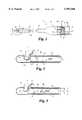
- FIG. 1is a partial cutaway view of a surgical cutting instrument in accordance with a preferred embodiment or the present invention.
- FIG. 2is a side cross-sectional view of the cutting instrument in FIG. 1, taken along line 2--2 as viewed in the direction of the arrows.
- FIG. 3is a side cross-sectional view similar to the view in FIG. 2 depicting the instrument with the blade positioned to cut a segment of tissue.
- FIG. 4is a top elevational view of the inner cutting member or cannula showing the cutting head and hinge segment.
- FIG. 5is a side partial cutaway view of an alternative embodiment to the surgical cutting instrument of the present invention.
- FIG. 6is a cross sectional view of the cutting head of the alternative embodiment, taken along line 6--6 as shown in the direction of the arrows in FIG. 5.
- FIG. 7is a bottom elevational view of another embodiment of the inner cutting member showing a cutting head similar to that depicted in FIG. 4 with the provision of a longitudinal slot.
- FIG. 8is a pictorial representation of the inner cutting member of FIG. 7.
- a surgical cutting instrument 10is shown in FIG. 1 which is adapted for percutaneous insertion at the surgical site, and is specifically adapted to cut tissue in the spinal region.
- the instrument 10includes a hand piece 11 which supports an outer cannula 13.
- the outer cannulahas a blunt distal tip 15 to minimize trauma to tissue as the cutting instrument is manipulated in the surgical site.
- the outer cannula 13includes a cutting opening 14 formed therethrough which opens to a central bore 16 extending through the length of the cannula 13.
- the cutting opening 14defines a cutting edge 18, which in the preferred embodiment is defined by a beveled cut in the wall of the outer cannula.
- the cutting opening 14is in the shape of an isosceles triangle.
- the cutting edge 18 in the specific embodimentis defined at the side of the triangle, but excludes the base of the triangular shape as shown in FIG. 1.
- the cutting instrument 10further includes an inner cannula 20 which is slidably and concentrically disposed within the outer cannula 13.
- the inner cannula 20terminates in a cutting edge 22 at the end opening 23 of the cannula.
- the end opening 23opens into an aspiration passageway 25 extending through the entire length of the inner cannula 20.
- the outer cannula 13is supported by the hand piece 11, while the inner cannula 20 also extends into the hand piece 11 to engage a drive mount 30 at a cannula support portion 33.
- the drive mountis engaged to a drive rod 31 that is connected to a motor or suitable mechanism for providing reciprocating motion. Specifically, the drive rod 31 and mount 30 reciprocate axially in the direction of the arrows R shown in FIGS. 1 and 2. Since the inner cannula 20 is fixed to the drive mount 30 it too reciprocates within the outer cannula 13. As the inner cannula 20 reciprocates, the inner surface of the outer cannula and the outer surface of the inner cannula operate as a bearing surface for the smooth movement of the inner cannula.
- the drive mount 30includes an aspiration chamber 34 which is connected through an aspiration tube 36 to a suitable vacuum source and tissue collection chamber in a manner well known in the art.
- the aspiration tube 36is engaged to the reciprocating drive mount 30.
- This aspectrequires the definition of a slot 38 in the hand piece 11 to allow the tube 36 room to move as it reciprocates with the drive mount.
- the instrument 10incorporates many features of known reciprocating cutters, particularly those implementing the "tube within a tube” approach.
- these types of cuttersare inherently limited in the type of tissues that can be cut and in the cutting speeds at which they are capable of operating.
- the present inventionprovides a means to allow the cutting instrument 10 to cut much tougher tissue than prior art devices, while still maintaining the minimally invasive dimensions of the instrument for percutaneous or intratrocar insertion.
- the inner cannula 20includes a hinge slot 40 cut circumferentially around the cannula.
- the hinge slot 40defines a hinge segment 41 at the uncut portion of the cannula.
- This hinge segment 41is, in essence, a narrow arc segment of a tubular formed inner cannula.
- the slot 40further defines a cutting head 43 connected by the hinge segment 41 to the remaining body portion 44 of the cannula 20.
- FIG. 3The particular benefit of this configuration for the inner cannula 20 is depicted more clearly in FIG. 3. (It is understood that the relative dimensions of the cutter components have been exaggerated for clarity.) It is known that as a reciprocating cutter engages and attempts to severe tissue T drawn into the cutting opening the tissue inherently resists the cutting action. As a portion of tissue T 1 is being severed, it exerts a reactive force F against the cutting edge 22 of the inner cannula 20. In a typical tube within a tube reciprocating cutter, this reactive or resistive force F is withstood by the cannula without any significant bending or movement of the solid inner cannula. Thus, with prior devices the clearance between the cutting edge remains constant, which permits a strand of tissue to remain in the gap between the inner and outer tubes. Frequently, the tissue is not excised on the first stroke of the cutting blade.
- the cutting head 43is permitted to pivot in the direction of the arrow P in FIG. 3.
- the inner cannula 20advances toward the cutting opening 14 of the outer cannula, it maintains a clearance C between the two tubes.
- the cutting head 43contacts the tissue it pivots so that the cutting edge 22 forms a zero clearance interface with the cutting edge 18 of the outer cannula cutting opening 14.
- This zero clearancefacilitates cutting the tissue segment T 1 , completely severing a strand of tissue between the inner and outer cannulae. This feature eliminates the gap, typically exists between the cutting edges of the prior art devices.
- each of the cutting componentsare formed of stainless steel, preferably 304SS typically used in medical grade components.
- stainless steelpreferably 304SS typically used in medical grade components.
- larger tolerancesmake the problem of tissue strands even greater as the tissue has more room to "hide" from the cutting edges. Prior art devices must wrestle with these clearance issues.
- the hinge slot 40 and hinge segment 41readily accommodate cutting instruments which are toleranced to +0.025 mm on both the inner diameter of the outer cannula and the outer diameter of the inner cannula.
- the cutting opening 14has a width W, as shown in FIG. 1, that is equal to approximately one half the inner diameter D 1 (see FIG. 3) of the outer cannula 13.
- the cutting opening 14is placed as close to the rounded distal tip 15 as possible.
- the outer diameter of the outer cannula 13is preferably less than about 5 mm. Thus, this dimension would dictate a cutting opening width W of about 21/2 mm.
- the cutting head 43 of the inner cannula 20has a length L (FIG. 4) which is long enough to allow the entire width of the cutting opening 14 to be occluded at the end of the stroke of the inner cannula 20.
- the length L of the cutting head 43is at least equal to the cutting opening width W in the outer cannula 13.
- the slot 40 that defines the hinge segment 41extends through about 90% of the inner cannula diameter.
- the arc hinge segment 41subtends an angle of about 70-80° with a chord length of about 1/2 the diameter D 2 .
- the hinge segment 41has a length H which is preferably about one fourth the diameter D 2 of the inner cannula 20.
- the length H of the hinge segment 41must be long enough to permit pivoting of the cutting head 43 in the direction P as the tissue is cut, yet strong enough to withstand cyclic bending as the cutter is used.
- the length H of the hinge segment 41is about 0.75 mm for a cutter driven by a motor capable of operation at speeds ranging between 15 to 250 strokes per second. The hinge will flex twice for each cycle as the cutting head pivots up to cut and back down on the return stroke.
- the arc configuration of the hinge segment 41increases its stiffness fatigue capability.
- FIGS. 5 and 6An alternative embodiment of the surgical cutting instrument of the present invention is shown in FIGS. 5 and 6.
- an outer cannula 50is provided which is substantially similar in construction to the outer cannula 13 previously described.
- a hand piece 52is provided for supporting the outer cannula.
- the inner cannula 55 of this embodimentis modified somewhat from the previous embodiment.
- This configurationincludes a cutting head 56 which is sized and shaped similar to the cutting head 43 of the embodiment in FIGS. 2 and 3.
- the hinge segmentis extended through most of the length of the inner cannula to define a body portion 58.
- the body portionis defined by an arc segment from a tubular form, preferably subtending an angle of about 70-80°.
- This body portion 58is engaged to a drive mount 60 which is itself engaged to a drive rod 61 to provide an axial reciprocating movement to the cutting head 56.
- the hand piece 52defines an aspiration chamber 65 which is connected by an aspiration tube 68 to a vacuum source.
- the aspiration chamber 65open directly to the interior of the outer cannula, thereby providing a greater aspiration flow path.
- the inner cannula 55includes a full cylindrical segment only at the cutting head 56.
- the cutting head 56will exhibit the same pivoting aspect about the body portion 58 as with the previous embodiment.
- the reduced profile of the inner cannula throughout most of its length, achieved by the arc form of the body portion 58reduces the sliding friction between the inner cannula 55 and the outer cannula 50.
- This embodimentretains the benefit of pivoting the cutting edge of the cutting head into a zero clearance with the cutting opening of the outer cannula 50 as the tissue is being excised.
- a smaller motorcan be used to drive the entire cutting assembly. This specific embodiment is preferably reserved for less rigorous tissue.
- FIGS. 7 and 8An inner cutting member 70 of an alternative embodiment of the invention is shown in FIGS. 7 and 8. It is understood that this cutting member 70 is reciprocatingly disposed within an outer cannula, such as cannula 13, in a manner similar to the previous embodiments.
- the cutting member 70is similar to the member 20 shown in FIG. 4.
- the inner cutting member 70, or inner cannulaincludes a cutting head 72 with a cutting edge 73.
- the cutting head 72is formed by the provision of a circumferential slot 75 defined in the cutting member 70.
- the slotfurther forms a hinge segment 76 so that the cutting head 72 is capable of the same hinged cutting performance as the previous embodiments.
- the present embodimentcontemplates the addition of a longitudinal slot 78 in the cutting head 72.
- the longitudinal slot 78extends from the cutting edge 73 to the circumferential hinge slot 75.
- the slot 78is preferably, but not necessarily, defined parallel to the longitudinal axis of the inner cutting cannula 70.
- the longitudinal slot 78permits circumferential expansion or contraction of the cutting head 72. Circumferential expansion further ensures a zero clearance between the cutting edge 73 and the cutting opening of the outer cannula. Circumferential contraction on the return stroke of the inner cannula 70 reduces the sliding friction between the inner and outer members.
- the circumferential expansion of the cutting head 72occurs during the cutting stroke. As the cutting head encounters resistance from the tissue extending through the outer cannula cutting opening, the head pivots upward about the hinge segment 76. It is further contemplated that the longitudinal slot 78 can widen against the resistance of the tissue, thereby allowing the cutting head to circumferentially expand against the outer cannula. Alternatively, the cutting head 72 can be preformed so that the cutting head is expanded into contact with the outer cannula when the cutting instrument is assembled. For a variety of reasons, it is either difficult or undesirable to use an inner cannula having an outer diameter that is exactly equal to the inner diameter of the outer cannula.
- Manufacturing tolerancesdictate that the nominal diameter of the inner cannula be less than the inner diameter of the outer cannula. Moreover, a smooth sliding fit between the two cannula further requires some clearance between the two components. These same considerations, however, decrease the cutting efficiency of the cutting edge of the inner cannula against the cutting opening of the outer cannula.
- the longitudinal slot 78can be preformed with the slot expanded so that the cutting head has a diameter greater than the rest of the inner cutting cannula. This further ensures a zero clearance at the cutting interface between inner and outer cutting edges.
- This inventioncontemplates a reciprocating cutter having a hinged cutting head portion. While the preferred embodiments encompass an inner cannula constructed with the hinge integrally formed between the cutting head and the body of the cannula, alternative hinge constructions are contemplated. For example, the cutting head portion may be separate from the body of the inner cannula with a hinge connecting the two parts.
Landscapes
- Health & Medical Sciences (AREA)
- Surgery (AREA)
- Life Sciences & Earth Sciences (AREA)
- Biomedical Technology (AREA)
- Nuclear Medicine, Radiotherapy & Molecular Imaging (AREA)
- Engineering & Computer Science (AREA)
- Orthopedic Medicine & Surgery (AREA)
- Heart & Thoracic Surgery (AREA)
- Medical Informatics (AREA)
- Molecular Biology (AREA)
- Animal Behavior & Ethology (AREA)
- General Health & Medical Sciences (AREA)
- Public Health (AREA)
- Veterinary Medicine (AREA)
- Surgical Instruments (AREA)
Abstract
Description
Claims (29)
Priority Applications (1)
| Application Number | Priority Date | Filing Date | Title |
|---|---|---|---|
| US09/118,045US5997560A (en) | 1994-07-21 | 1998-07-17 | Surgical cutting instrument |
Applications Claiming Priority (2)
| Application Number | Priority Date | Filing Date | Title |
|---|---|---|---|
| US08/278,558US5782849A (en) | 1993-05-07 | 1994-07-21 | Surgical cutting instrument |
| US09/118,045US5997560A (en) | 1994-07-21 | 1998-07-17 | Surgical cutting instrument |
Related Parent Applications (1)
| Application Number | Title | Priority Date | Filing Date |
|---|---|---|---|
| US08/278,558ContinuationUS5782849A (en) | 1993-05-07 | 1994-07-21 | Surgical cutting instrument |
Publications (1)
| Publication Number | Publication Date |
|---|---|
| US5997560Atrue US5997560A (en) | 1999-12-07 |
Family
ID=23065466
Family Applications (1)
| Application Number | Title | Priority Date | Filing Date |
|---|---|---|---|
| US09/118,045Expired - LifetimeUS5997560A (en) | 1994-07-21 | 1998-07-17 | Surgical cutting instrument |
Country Status (1)
| Country | Link |
|---|---|
| US (1) | US5997560A (en) |
Cited By (57)
| Publication number | Priority date | Publication date | Assignee | Title |
|---|---|---|---|---|
| US6419641B1 (en)* | 2000-11-28 | 2002-07-16 | Promex, Llc | Flexible tip medical instrument |
| US6638235B2 (en) | 2000-11-06 | 2003-10-28 | Suros Surgical Systems, Inc. | Biopsy apparatus |
| US20040167427A1 (en)* | 2003-02-24 | 2004-08-26 | Senorx, Inc. | Biopsy device with inner cutter |
| US20050029372A1 (en)* | 2001-12-26 | 2005-02-10 | Castronovo Charles A. | Zero-clearance cutting systems |
| US20050040264A1 (en)* | 2001-12-26 | 2005-02-24 | Castronovo Charles A. | Double-secondary shredders in zero-clearance cutting systems |
| US20050113715A1 (en)* | 2000-11-06 | 2005-05-26 | Jeffrey Schwindt | Biopsy apparatus |
| US20050150986A1 (en)* | 2001-12-26 | 2005-07-14 | Castronovo Charles A. | Self-healing cutting apparatus and other self-healing machinery |
| US20050197661A1 (en)* | 2004-03-03 | 2005-09-08 | Scimed Life Systems, Inc. | Tissue removal probe with sliding burr in cutting window |
| US20050209622A1 (en)* | 2004-03-03 | 2005-09-22 | Scimed Life Systems, Inc. | Tissue removal probe with irrigation and aspiration ports |
| US20060130093A1 (en)* | 2004-12-15 | 2006-06-15 | Liangkui Feng | Electronic program guide display and cursor control |
| US20070055259A1 (en)* | 2005-08-17 | 2007-03-08 | Norton Britt K | Apparatus and methods for removal of intervertebral disc tissues |
| US20070162062A1 (en)* | 2005-12-08 | 2007-07-12 | Norton Britt K | Reciprocating apparatus and methods for removal of intervertebral disc tissues |
| US20080228198A1 (en)* | 2007-03-13 | 2008-09-18 | Mitralign, Inc. | Suture cutter and method of cutting suture |
| US7458940B2 (en) | 2000-11-06 | 2008-12-02 | Suros Surgical Systems, Inc. | Biopsy apparatus |
| US7556622B2 (en) | 2005-05-18 | 2009-07-07 | Suros Surgical Systems, Inc. | Selectively openable tissue filter |
| US7572236B2 (en) | 2005-08-05 | 2009-08-11 | Senorx, Inc. | Biopsy device with fluid delivery to tissue specimens |
| US20100152533A1 (en)* | 2008-12-16 | 2010-06-17 | Mark Joseph L | Tissue removal device for use with imaging devices in neurosurgical and spinal surgery applications |
| US20100152760A1 (en)* | 2008-12-16 | 2010-06-17 | Mark Joseph L | Tissue removal device for neurosurgical and spinal surgery applications |
| US20100152762A1 (en)* | 2008-12-16 | 2010-06-17 | Mark Joseph L | Tissue removal system with multi-directional foot actuator assembly for neurosurgical and spinal surgery applications |
| US20100152761A1 (en)* | 2008-12-16 | 2010-06-17 | Mark Joseph L | Tissue removal device for neurosurgical and spinal surgery applications |
| US20100152614A1 (en)* | 2008-12-16 | 2010-06-17 | Mark Joseph L | Tissue removal device for neurosurgical and spinal surgery applications |
| US20100152756A1 (en)* | 2008-12-16 | 2010-06-17 | Mark Joseph L | Tissue removal device for neurosurgical and spinal surgery applications |
| US20100152758A1 (en)* | 2008-12-16 | 2010-06-17 | Mark Joseph L | Tissue removal device for neurosurgical and spinal surgery applications |
| US20100152615A1 (en)* | 2008-12-16 | 2010-06-17 | Mark Joseph L | Tissue removal device with adjustable fluid supply sleeve for neurosurgical and spinal surgery applications |
| US20100249817A1 (en)* | 2008-12-16 | 2010-09-30 | Mark Joseph L | Positioning system for tissue removal device |
| US20100305470A1 (en)* | 2009-05-29 | 2010-12-02 | Promex Technologies, Llc | Flexible biopsy needle |
| EP1599125A4 (en)* | 2003-02-24 | 2011-02-16 | Senorx Inc | Biopsy device with inner cutting member |
| US20110152773A1 (en)* | 2009-12-22 | 2011-06-23 | Mccawley Matthew D | Trocar cannula device with retention feature |
| US7988642B2 (en) | 2003-10-14 | 2011-08-02 | Suros Surgical Systems, Inc. | Vacuum assisted biopsy device |
| US8048003B2 (en) | 2003-10-14 | 2011-11-01 | Suros Surgical Systems, Inc. | Vacuum assisted biopsy device |
| US8100353B2 (en) | 2001-12-26 | 2012-01-24 | Castronovo Charles A | Self-healing cutting apparatus and other self-healing machinery |
| US8187204B2 (en) | 2007-10-01 | 2012-05-29 | Suros Surgical Systems, Inc. | Surgical device and method for using same |
| US8231544B2 (en) | 2003-10-14 | 2012-07-31 | Suros Surgical Systems, Inc. | Vacuum assisted biopsy needle set |
| US8277418B2 (en) | 2009-12-23 | 2012-10-02 | Alcon Research, Ltd. | Ophthalmic valved trocar cannula |
| US8282573B2 (en) | 2003-02-24 | 2012-10-09 | Senorx, Inc. | Biopsy device with selectable tissue receiving aperture orientation and site illumination |
| US8317725B2 (en) | 2005-08-05 | 2012-11-27 | Senorx, Inc. | Biopsy device with fluid delivery to tissue specimens |
| US8343106B2 (en) | 2009-12-23 | 2013-01-01 | Alcon Research, Ltd. | Ophthalmic valved trocar vent |
| US8343071B2 (en) | 2004-12-16 | 2013-01-01 | Senorx, Inc. | Biopsy device with aperture orientation and improved tip |
| US8465471B2 (en) | 2009-08-05 | 2013-06-18 | Rocin Laboratories, Inc. | Endoscopically-guided electro-cauterizing power-assisted fat aspiration system for aspirating visceral fat tissue within the abdomen of a patient |
| US8529468B2 (en) | 2009-07-01 | 2013-09-10 | Suros Surgical Systems, Inc. | Surgical system |
| US8641640B2 (en) | 2005-05-23 | 2014-02-04 | Senorx, Inc. | Tissue cutting member for a biopsy device |
| US8808200B2 (en) | 2007-10-01 | 2014-08-19 | Suros Surgical Systems, Inc. | Surgical device and method of using same |
| US8932233B2 (en) | 2004-05-21 | 2015-01-13 | Devicor Medical Products, Inc. | MRI biopsy device |
| US9279751B2 (en) | 2008-12-16 | 2016-03-08 | Nico Corporation | System and method of taking and collecting tissue cores for treatment |
| US9358111B2 (en) | 2007-03-13 | 2016-06-07 | Mitralign, Inc. | Tissue anchors, systems and methods, and devices |
| US9408592B2 (en) | 2003-12-23 | 2016-08-09 | Senorx, Inc. | Biopsy device with aperture orientation and improved tip |
| US9463465B2 (en) | 2012-09-06 | 2016-10-11 | Charles A. Castronovo | Compact high-security destruction machine |
| US9504247B2 (en) | 2008-12-16 | 2016-11-29 | Nico Corporation | System for collecting and preserving tissue cores |
| US9638770B2 (en) | 2004-05-21 | 2017-05-02 | Devicor Medical Products, Inc. | MRI biopsy apparatus incorporating an imageable penetrating portion |
| US9795365B2 (en) | 2004-05-21 | 2017-10-24 | Devicor Medical Products, Inc. | MRI biopsy apparatus incorporating a sleeve and multi-function obturator |
| US9820480B2 (en) | 2008-12-16 | 2017-11-21 | Nico Corporation | System for collecting and preserving tissue cores |
| US9925314B2 (en) | 2009-08-05 | 2018-03-27 | Rocin Laboratories, Inc. | Method of performing intra-abdominal tissue aspiration to ameliorate the metabolic syndrome, or abdominal obesity |
| US9931105B2 (en) | 2008-12-16 | 2018-04-03 | Nico Corporation | System and method of taking and collecting tissue cores for treatment |
| US10080578B2 (en) | 2008-12-16 | 2018-09-25 | Nico Corporation | Tissue removal device with adjustable delivery sleeve for neurosurgical and spinal surgery applications |
| US10368890B2 (en) | 2008-12-16 | 2019-08-06 | Nico Corporation | Multi-functional surgical device for neurosurgical and spinal surgery applications |
| US10918373B2 (en) | 2013-08-31 | 2021-02-16 | Edwards Lifesciences Corporation | Devices and methods for locating and implanting tissue anchors at mitral valve commissure |
| US11660190B2 (en) | 2007-03-13 | 2023-05-30 | Edwards Lifesciences Corporation | Tissue anchors, systems and methods, and devices |
Citations (1)
| Publication number | Priority date | Publication date | Assignee | Title |
|---|---|---|---|---|
| US5782849A (en)* | 1993-05-07 | 1998-07-21 | Sdgi Holdings, Inc. | Surgical cutting instrument |
- 1998
- 1998-07-17USUS09/118,045patent/US5997560A/ennot_activeExpired - Lifetime
Patent Citations (1)
| Publication number | Priority date | Publication date | Assignee | Title |
|---|---|---|---|---|
| US5782849A (en)* | 1993-05-07 | 1998-07-21 | Sdgi Holdings, Inc. | Surgical cutting instrument |
Cited By (161)
| Publication number | Priority date | Publication date | Assignee | Title |
|---|---|---|---|---|
| US8277393B2 (en) | 2000-11-06 | 2012-10-02 | Suros Surgical Systems, Inc. | Biopsy apparatus |
| US20050113715A1 (en)* | 2000-11-06 | 2005-05-26 | Jeffrey Schwindt | Biopsy apparatus |
| US6638235B2 (en) | 2000-11-06 | 2003-10-28 | Suros Surgical Systems, Inc. | Biopsy apparatus |
| US7458940B2 (en) | 2000-11-06 | 2008-12-02 | Suros Surgical Systems, Inc. | Biopsy apparatus |
| US6758824B1 (en) | 2000-11-06 | 2004-07-06 | Suros Surgical Systems, Inc. | Biopsy apparatus |
| US8109886B2 (en) | 2000-11-06 | 2012-02-07 | Suros Surgical Systems, Inc. | Biopsy apparatus |
| US8167818B2 (en) | 2000-11-06 | 2012-05-01 | Suros Surgical Systems, Inc. | Biopsy apparatus with vacuum relief |
| US8192370B2 (en) | 2000-11-06 | 2012-06-05 | Suros Surgical Systems, Inc. | Biopsy apparatus |
| US7497833B2 (en) | 2000-11-06 | 2009-03-03 | Suros Surgical Systems, Inc. | Biopsy apparatus with vacuum relief |
| US7883476B2 (en) | 2000-11-06 | 2011-02-08 | Suros Surgical Systems, Inc. | Selectively detachable outer cannula hub |
| US8986222B2 (en) | 2000-11-06 | 2015-03-24 | Hologic, Inc. | Biopsy apparatus |
| US8764679B2 (en) | 2000-11-06 | 2014-07-01 | Suros Surgical Systems, Inc. | Biopsy apparatus |
| US8568332B2 (en) | 2000-11-06 | 2013-10-29 | Suros Surgical Systems, Inc. | Biopsy apparatus |
| US7837630B2 (en) | 2000-11-06 | 2010-11-23 | Suros Surgical Systems, Inc. | Fluid control element for biopsy apparatus |
| US7841990B2 (en) | 2000-11-28 | 2010-11-30 | Promex Technologies, Llc | Flexible tip medical instrument |
| US20060184153A1 (en)* | 2000-11-28 | 2006-08-17 | Promex Technologies, Llc | Flexible tip medical instrument |
| US20050113714A1 (en)* | 2000-11-28 | 2005-05-26 | Promex Technologies, Llc | Flexible tip medical instrument |
| WO2002060312A3 (en)* | 2000-11-28 | 2003-04-17 | Promex Inc | Flexible tip medical instrument |
| US7048694B2 (en)* | 2000-11-28 | 2006-05-23 | Promex Technologies, Llc | Flexible tip medical instrument |
| US6419641B1 (en)* | 2000-11-28 | 2002-07-16 | Promex, Llc | Flexible tip medical instrument |
| US20030208136A1 (en)* | 2000-11-28 | 2003-11-06 | Promex, Inc. | Flexible tip medical instrument |
| US7240864B2 (en) | 2001-12-26 | 2007-07-10 | Castronovo Charles A | Helical cutting |
| US7448562B2 (en) | 2001-12-26 | 2008-11-11 | Castronovo Charles A | High-security destruction including sacrificial cutting followed by non-sacrificial cutting |
| US7090156B2 (en) | 2001-12-26 | 2006-08-15 | Castronovo Charles A | Destroying planar material |
| US20060175446A1 (en)* | 2001-12-26 | 2006-08-10 | Castronovo Charles A | Feeding mechanism |
| US7100852B2 (en) | 2001-12-26 | 2006-09-05 | Castronovo Charles A | Helical cutting |
| US20060196980A1 (en)* | 2001-12-26 | 2006-09-07 | Castronovo Charles A | Residue exit for security destruction machines |
| US20060208117A1 (en)* | 2001-12-26 | 2006-09-21 | Castronovo Charles A | Destroying planar material into high security pieces |
| US7111801B2 (en) | 2001-12-26 | 2006-09-26 | Castronovo Charles A | Destroying non-homogeneous loads using zero-clearance cutting systems, double-secondary shredders in zero-clearance cutting systems, and other zero-clearance systems |
| US20060249607A1 (en)* | 2001-12-26 | 2006-11-09 | Castronovo Charles A | Helical cutting |
| US20070018021A1 (en)* | 2001-12-26 | 2007-01-25 | Castronovo Charles A | Sacrificial rotary scissors |
| US7175116B2 (en) | 2001-12-26 | 2007-02-13 | Castronovo Charles A | High-security cutting |
| US20050029372A1 (en)* | 2001-12-26 | 2005-02-10 | Castronovo Charles A. | Zero-clearance cutting systems |
| US20050029377A1 (en)* | 2001-12-26 | 2005-02-10 | Castronovo Charles A. | Zero-clearance cutting systems |
| US7204436B2 (en) | 2001-12-26 | 2007-04-17 | Castronovo Charles A | Residue exit for security destruction machines |
| US20070108325A1 (en)* | 2001-12-26 | 2007-05-17 | Castronovo Charles A | Motorized Sacrificial Material |
| US8100353B2 (en) | 2001-12-26 | 2012-01-24 | Castronovo Charles A | Self-healing cutting apparatus and other self-healing machinery |
| US20050040264A1 (en)* | 2001-12-26 | 2005-02-24 | Castronovo Charles A. | Double-secondary shredders in zero-clearance cutting systems |
| US20050040267A1 (en)* | 2001-12-26 | 2005-02-24 | Castronovo Charles A. | Zero-clearance cutting systems |
| US20070164142A1 (en)* | 2001-12-26 | 2007-07-19 | Castronovo Charles A | Destruction Method With 45 Degree Feeding |
| US20070187533A1 (en)* | 2001-12-26 | 2007-08-16 | Castronovo Charles A | Screenless Disintegrators |
| US7267294B2 (en) | 2001-12-26 | 2007-09-11 | Castronovo Charles A | Zero-clearance cutting systems |
| US7270282B2 (en) | 2001-12-26 | 2007-09-18 | Castronovo Charles A | Screenless disintegrators |
| US7334747B2 (en) | 2001-12-26 | 2008-02-26 | Castronovo Charles A | Destroying planar material into high security pieces |
| US7357340B2 (en) | 2001-12-26 | 2008-04-15 | Castronovo Charles A | Destruction method with 45 degree feeding |
| US7424981B2 (en) | 2001-12-26 | 2008-09-16 | Castronovo Charles A | Destroying a non-homogeneous load |
| US20050040268A1 (en)* | 2001-12-26 | 2005-02-24 | Castronovo Charles A. | Zero-clearance cutting systems |
| US7090214B2 (en) | 2001-12-26 | 2006-08-15 | Castronovo Charles A | Feeding mechanism |
| US20050120841A1 (en)* | 2001-12-26 | 2005-06-09 | Castronovo Charles A. | Zero-clearance cutting systems |
| US20060124785A1 (en)* | 2001-12-26 | 2006-06-15 | Castronovo Charles A | Destroying a non-homogeneous load |
| US7500625B2 (en) | 2001-12-26 | 2009-03-10 | Castronovo Charles A | Feeding mechanism |
| US20050150986A1 (en)* | 2001-12-26 | 2005-07-14 | Castronovo Charles A. | Self-healing cutting apparatus and other self-healing machinery |
| US8292204B2 (en) | 2001-12-26 | 2012-10-23 | Castronovo Charles A | Motorized sacrificial material |
| US7607598B2 (en) | 2001-12-26 | 2009-10-27 | Castronovo Charles A | Self-healing cutting apparatus and other self-healing machinery |
| US20100019073A1 (en)* | 2001-12-26 | 2010-01-28 | Castronovo Charles A | Destroying Paper Into High Security Pieces, Powderizing Methods, and Other High-Security Destruction |
| US8297544B2 (en) | 2001-12-26 | 2012-10-30 | Castronovo Charles A | Screenless disintegrators |
| US8408484B2 (en) | 2001-12-26 | 2013-04-02 | Charles A. Castronovo | Zero-clearance cutting machine |
| US8596564B2 (en) | 2001-12-26 | 2013-12-03 | Charles A. Castronovo | Destroying paper into high security pieces, powderizing methods, and other high-security destruction |
| US6938844B2 (en) | 2001-12-26 | 2005-09-06 | Charles A. Castronovo | Zero-clearance cutting systems |
| US10335127B2 (en)* | 2003-02-24 | 2019-07-02 | Senorx, Inc. | Biopsy device with selectable tissue receiving aperature orientation and site illumination |
| US10231715B2 (en) | 2003-02-24 | 2019-03-19 | Senorx, Inc. | Biopsy device with inner cutting member |
| US11534147B2 (en) | 2003-02-24 | 2022-12-27 | Senorx, Inc. | Biopsy device with a removable sample recieving cartridge |
| US9044215B2 (en) | 2003-02-24 | 2015-06-02 | Senorx, Inc. | Biopsy device with selectable tissue receiving aperature orientation and site illumination |
| US8282573B2 (en) | 2003-02-24 | 2012-10-09 | Senorx, Inc. | Biopsy device with selectable tissue receiving aperture orientation and site illumination |
| US20150230778A1 (en)* | 2003-02-24 | 2015-08-20 | Senorx, Inc. | Biopsy device with selectable tissue receiving aperature orientation and site illumination |
| US20070161925A1 (en)* | 2003-02-24 | 2007-07-12 | Senorx, Inc. | Biopsy device with inner cutter |
| US8460204B2 (en) | 2003-02-24 | 2013-06-11 | Senorx, Inc. | Biopsy device with inner cutting member |
| US11589849B2 (en) | 2003-02-24 | 2023-02-28 | Senorx, Inc. | Biopsy device with selectable tissue receiving aperature orientation and site illumination |
| EP1599125A4 (en)* | 2003-02-24 | 2011-02-16 | Senorx Inc | Biopsy device with inner cutting member |
| US10172595B2 (en) | 2003-02-24 | 2019-01-08 | Senorx, Inc. | Biopsy device with selectable tissue receiving aperture orientation and site illumination |
| US7189206B2 (en) | 2003-02-24 | 2007-03-13 | Senorx, Inc. | Biopsy device with inner cutter |
| US9204866B2 (en) | 2003-02-24 | 2015-12-08 | Senorx, Inc. | Biopsy device with selectable tissue receiving aperture orientation and site illumination |
| US20040167427A1 (en)* | 2003-02-24 | 2004-08-26 | Senorx, Inc. | Biopsy device with inner cutter |
| US8231544B2 (en) | 2003-10-14 | 2012-07-31 | Suros Surgical Systems, Inc. | Vacuum assisted biopsy needle set |
| US8048003B2 (en) | 2003-10-14 | 2011-11-01 | Suros Surgical Systems, Inc. | Vacuum assisted biopsy device |
| US7988642B2 (en) | 2003-10-14 | 2011-08-02 | Suros Surgical Systems, Inc. | Vacuum assisted biopsy device |
| US8430827B2 (en) | 2003-10-14 | 2013-04-30 | Suros Surgical Sysytems, Inc. | Vacuum assisted biopsy device |
| US9408592B2 (en) | 2003-12-23 | 2016-08-09 | Senorx, Inc. | Biopsy device with aperture orientation and improved tip |
| US20050197661A1 (en)* | 2004-03-03 | 2005-09-08 | Scimed Life Systems, Inc. | Tissue removal probe with sliding burr in cutting window |
| US20050209622A1 (en)* | 2004-03-03 | 2005-09-22 | Scimed Life Systems, Inc. | Tissue removal probe with irrigation and aspiration ports |
| US8932233B2 (en) | 2004-05-21 | 2015-01-13 | Devicor Medical Products, Inc. | MRI biopsy device |
| US9392999B2 (en) | 2004-05-21 | 2016-07-19 | Devicor Medical Products, Inc. | MRI biopsy device |
| US9504453B2 (en) | 2004-05-21 | 2016-11-29 | Devicor Medical Products, Inc. | MRI biopsy device |
| US9638770B2 (en) | 2004-05-21 | 2017-05-02 | Devicor Medical Products, Inc. | MRI biopsy apparatus incorporating an imageable penetrating portion |
| US9795365B2 (en) | 2004-05-21 | 2017-10-24 | Devicor Medical Products, Inc. | MRI biopsy apparatus incorporating a sleeve and multi-function obturator |
| US20060130093A1 (en)* | 2004-12-15 | 2006-06-15 | Liangkui Feng | Electronic program guide display and cursor control |
| US8360990B2 (en) | 2004-12-16 | 2013-01-29 | Senorx, Inc. | Biopsy device with aperture orientation and improved tip |
| US10105125B2 (en) | 2004-12-16 | 2018-10-23 | Senorx, Inc. | Biopsy device with aperture orientation and improved tip |
| US11246574B2 (en) | 2004-12-16 | 2022-02-15 | Senorx, Inc. | Biopsy device with aperture orientation and improved tip |
| US8343071B2 (en) | 2004-12-16 | 2013-01-01 | Senorx, Inc. | Biopsy device with aperture orientation and improved tip |
| US7556622B2 (en) | 2005-05-18 | 2009-07-07 | Suros Surgical Systems, Inc. | Selectively openable tissue filter |
| US9095325B2 (en) | 2005-05-23 | 2015-08-04 | Senorx, Inc. | Tissue cutting member for a biopsy device |
| US10478161B2 (en) | 2005-05-23 | 2019-11-19 | Senorx, Inc. | Tissue cutting member for a biopsy device |
| US9750487B2 (en) | 2005-05-23 | 2017-09-05 | Senorx, Inc. | Tissue cutting member for a biopsy device |
| US11426149B2 (en) | 2005-05-23 | 2022-08-30 | SenoRx., Inc. | Tissue cutting member for a biopsy device |
| US8641640B2 (en) | 2005-05-23 | 2014-02-04 | Senorx, Inc. | Tissue cutting member for a biopsy device |
| US8317725B2 (en) | 2005-08-05 | 2012-11-27 | Senorx, Inc. | Biopsy device with fluid delivery to tissue specimens |
| US10874381B2 (en) | 2005-08-05 | 2020-12-29 | Senorx, Inc. | Biopsy device with fluid delivery to tissue specimens |
| US10064609B2 (en) | 2005-08-05 | 2018-09-04 | Senorx, Inc. | Method of collecting one or more tissue specimens |
| US7981051B2 (en) | 2005-08-05 | 2011-07-19 | Senorx, Inc. | Biopsy device with fluid delivery to tissue specimens |
| US8915864B2 (en) | 2005-08-05 | 2014-12-23 | Senorx, Inc. | Biopsy device with fluid delivery to tissue specimens |
| US7572236B2 (en) | 2005-08-05 | 2009-08-11 | Senorx, Inc. | Biopsy device with fluid delivery to tissue specimens |
| US20070055259A1 (en)* | 2005-08-17 | 2007-03-08 | Norton Britt K | Apparatus and methods for removal of intervertebral disc tissues |
| US20070162062A1 (en)* | 2005-12-08 | 2007-07-12 | Norton Britt K | Reciprocating apparatus and methods for removal of intervertebral disc tissues |
| US8911461B2 (en)* | 2007-03-13 | 2014-12-16 | Mitralign, Inc. | Suture cutter and method of cutting suture |
| US20080228198A1 (en)* | 2007-03-13 | 2008-09-18 | Mitralign, Inc. | Suture cutter and method of cutting suture |
| US9358111B2 (en) | 2007-03-13 | 2016-06-07 | Mitralign, Inc. | Tissue anchors, systems and methods, and devices |
| US11660190B2 (en) | 2007-03-13 | 2023-05-30 | Edwards Lifesciences Corporation | Tissue anchors, systems and methods, and devices |
| US8187204B2 (en) | 2007-10-01 | 2012-05-29 | Suros Surgical Systems, Inc. | Surgical device and method for using same |
| US8808200B2 (en) | 2007-10-01 | 2014-08-19 | Suros Surgical Systems, Inc. | Surgical device and method of using same |
| US8202229B2 (en) | 2007-10-01 | 2012-06-19 | Suros Surgical Systems, Inc. | Surgical device |
| US8430825B2 (en)* | 2008-12-16 | 2013-04-30 | Nico Corporation | Tissue removal device for neurosurgical and spinal surgery applications |
| US10959424B2 (en) | 2008-12-16 | 2021-03-30 | Nico Corporation | System for collecting and preserving tissue cores |
| US11759259B2 (en) | 2008-12-16 | 2023-09-19 | Nico Corporation | Tissue removal device with adjustable delivery sleeve for neurosurgical and spinal surgery applications |
| US20100152533A1 (en)* | 2008-12-16 | 2010-06-17 | Mark Joseph L | Tissue removal device for use with imaging devices in neurosurgical and spinal surgery applications |
| US9028518B2 (en)* | 2008-12-16 | 2015-05-12 | Nico Corporation | Tissue removal device for neurosurgical and spinal surgery applications |
| US20100152760A1 (en)* | 2008-12-16 | 2010-06-17 | Mark Joseph L | Tissue removal device for neurosurgical and spinal surgery applications |
| US8702738B2 (en) | 2008-12-16 | 2014-04-22 | Nico Corporation | Tissue removal device for neurosurgical and spinal surgery applications |
| US11609160B2 (en) | 2008-12-16 | 2023-03-21 | Nico Corporation | System and method of taking and collecting tissue cores for treatment |
| US8657841B2 (en) | 2008-12-16 | 2014-02-25 | Nico Corporation | Tissue removal device for neurosurgical and spinal surgery applications |
| US9216031B2 (en) | 2008-12-16 | 2015-12-22 | Nico Corporation | Tissue removal device with adjustable fluid supply sleeve for neurosurgical and spinal surgery applications |
| US9279751B2 (en) | 2008-12-16 | 2016-03-08 | Nico Corporation | System and method of taking and collecting tissue cores for treatment |
| US20100152762A1 (en)* | 2008-12-16 | 2010-06-17 | Mark Joseph L | Tissue removal system with multi-directional foot actuator assembly for neurosurgical and spinal surgery applications |
| US20100152761A1 (en)* | 2008-12-16 | 2010-06-17 | Mark Joseph L | Tissue removal device for neurosurgical and spinal surgery applications |
| US8888803B2 (en) | 2008-12-16 | 2014-11-18 | Nico Corporation | Tissue removal device for neurosurgical and spinal surgery applications |
| US20100249817A1 (en)* | 2008-12-16 | 2010-09-30 | Mark Joseph L | Positioning system for tissue removal device |
| US20130023916A1 (en)* | 2008-12-16 | 2013-01-24 | Mark Joseph L | Tissue removal device for neurosurgical and spinal surgery applications |
| US9504247B2 (en) | 2008-12-16 | 2016-11-29 | Nico Corporation | System for collecting and preserving tissue cores |
| US8496599B2 (en) | 2008-12-16 | 2013-07-30 | Nico Corporation | Tissue removal device for neurosurgical and spinal surgery applications |
| US20100152615A1 (en)* | 2008-12-16 | 2010-06-17 | Mark Joseph L | Tissue removal device with adjustable fluid supply sleeve for neurosurgical and spinal surgery applications |
| US20100152758A1 (en)* | 2008-12-16 | 2010-06-17 | Mark Joseph L | Tissue removal device for neurosurgical and spinal surgery applications |
| US9655639B2 (en) | 2008-12-16 | 2017-05-23 | Nico Corporation | Tissue removal device for use with imaging devices in neurosurgical and spinal surgery applications |
| US8460327B2 (en) | 2008-12-16 | 2013-06-11 | Nico Corporation | Tissue removal device for neurosurgical and spinal surgery applications |
| US20100152614A1 (en)* | 2008-12-16 | 2010-06-17 | Mark Joseph L | Tissue removal device for neurosurgical and spinal surgery applications |
| US9820480B2 (en) | 2008-12-16 | 2017-11-21 | Nico Corporation | System for collecting and preserving tissue cores |
| US10398462B2 (en) | 2008-12-16 | 2019-09-03 | Nico Corporation | Tissue removal device with adjustable sleeve for neurosurgical and spinal surgery applications |
| US10368890B2 (en) | 2008-12-16 | 2019-08-06 | Nico Corporation | Multi-functional surgical device for neurosurgical and spinal surgery applications |
| US9931105B2 (en) | 2008-12-16 | 2018-04-03 | Nico Corporation | System and method of taking and collecting tissue cores for treatment |
| US10048176B2 (en) | 2008-12-16 | 2018-08-14 | Nico Corporation | System and method of taking and collecting tissue cores for treatment |
| US8357175B2 (en) | 2008-12-16 | 2013-01-22 | Nico Corporation | Positioning system for tissue removal device |
| US10080578B2 (en) | 2008-12-16 | 2018-09-25 | Nico Corporation | Tissue removal device with adjustable delivery sleeve for neurosurgical and spinal surgery applications |
| US20100152756A1 (en)* | 2008-12-16 | 2010-06-17 | Mark Joseph L | Tissue removal device for neurosurgical and spinal surgery applications |
| EP3045125A1 (en)* | 2009-05-05 | 2016-07-20 | Nico Corporation | Tissue removal device for neurosurgical and spinal surgery applications |
| US9579087B2 (en) | 2009-05-29 | 2017-02-28 | Promex Technologies, Llc | Flexible biopsy needle |
| US8057403B2 (en) | 2009-05-29 | 2011-11-15 | Promex Technologies, Inc. | Flexible biopsy needle |
| US20100305470A1 (en)* | 2009-05-29 | 2010-12-02 | Promex Technologies, Llc | Flexible biopsy needle |
| US8858464B2 (en) | 2009-07-01 | 2014-10-14 | Suros Surgical Systems, Inc. | Surgical system |
| US8529468B2 (en) | 2009-07-01 | 2013-09-10 | Suros Surgical Systems, Inc. | Surgical system |
| US8465471B2 (en) | 2009-08-05 | 2013-06-18 | Rocin Laboratories, Inc. | Endoscopically-guided electro-cauterizing power-assisted fat aspiration system for aspirating visceral fat tissue within the abdomen of a patient |
| US11259862B2 (en) | 2009-08-05 | 2022-03-01 | Rocin Laboratories, Inc. | Coaxial-driven tissue aspiration instrument system |
| US9833279B2 (en) | 2009-08-05 | 2017-12-05 | Rocin Laboratories, Inc. | Twin-cannula tissue aspiration instrument system |
| US9925314B2 (en) | 2009-08-05 | 2018-03-27 | Rocin Laboratories, Inc. | Method of performing intra-abdominal tissue aspiration to ameliorate the metabolic syndrome, or abdominal obesity |
| US12171482B2 (en) | 2009-08-05 | 2024-12-24 | Rocin Laboratories, Inc. | Bariatric surgery operating room with a laparoscopic-based visceral fat tissue aspiration system configured and operational for treating metabolic syndrome in human patients on an ambulatory basis |
| US12178494B2 (en) | 2009-08-05 | 2024-12-31 | Rocin Laboratories, Inc | Laparoscopic-based method of safely removing visceral fat tissue deposits from within the mesenteric region of a human patient suffering from metabolic syndrome |
| US8062260B2 (en)* | 2009-12-22 | 2011-11-22 | Alcon Research, Ltd. | Trocar cannula device with retention feature |
| US20110152773A1 (en)* | 2009-12-22 | 2011-06-23 | Mccawley Matthew D | Trocar cannula device with retention feature |
| US8277418B2 (en) | 2009-12-23 | 2012-10-02 | Alcon Research, Ltd. | Ophthalmic valved trocar cannula |
| US8679064B2 (en) | 2009-12-23 | 2014-03-25 | Alcon Research, Ltd. | Ophthalmic valved trocar cannula |
| US8343106B2 (en) | 2009-12-23 | 2013-01-01 | Alcon Research, Ltd. | Ophthalmic valved trocar vent |
| US9463465B2 (en) | 2012-09-06 | 2016-10-11 | Charles A. Castronovo | Compact high-security destruction machine |
| US10918373B2 (en) | 2013-08-31 | 2021-02-16 | Edwards Lifesciences Corporation | Devices and methods for locating and implanting tissue anchors at mitral valve commissure |
Similar Documents
| Publication | Publication Date | Title |
|---|---|---|
| US5997560A (en) | Surgical cutting instrument | |
| US5782849A (en) | Surgical cutting instrument | |
| US5911701A (en) | Surgical cutting instrument | |
| US5423844A (en) | Rotary surgical cutting instrument | |
| US5411513A (en) | Transmission mechanism for a surgical cutting instrument | |
| US5395313A (en) | Reciprocating arthroscopic shaver | |
| US4844064A (en) | Surgical cutting instrument with end and side openings | |
| US5084052A (en) | Surgical cutting instrument with plurality of openings | |
| US9636130B2 (en) | Reciprocating rotary arthroscopic surgical instrument | |
| US5019035A (en) | Cutting assembly for surgical cutting instrument | |
| US4867157A (en) | Surgical cutting instrument | |
| US5387215A (en) | Surgical instrument for cutting hard tissue and method of use | |
| US4811734A (en) | Surgical cutting instrument | |
| EP1176915B1 (en) | Percutaneous material removal device | |
| EP0892621B1 (en) | Surgical instrument | |
| US6638289B1 (en) | Elongated endoscopic cutting accessories | |
| EP0609084A2 (en) | Powered rotatable curved instrument | |
| US20200029992A1 (en) | Surgical Tool Arrangement And Surgical Cutting Accessory For Use Therewith | |
| US6344038B1 (en) | Surgical anti-friction device | |
| CA2060758A1 (en) | Surgical cutting instrument | |
| JP2001507590A (en) | Surgical instruments | |
| WO2007065043A1 (en) | Method and apparatus for removing material from an intervertebral disc space, such as in performing a nucleotomy | |
| EP0669105A2 (en) | Endoscopic resection instrument | |
| KR102695580B1 (en) | Medical Blade Devices |
Legal Events
| Date | Code | Title | Description |
|---|---|---|---|
| STCF | Information on status: patent grant | Free format text:PATENTED CASE | |
| AS | Assignment | Owner name:SUROS SURGICAL SYSTEMS, INC., INDIANA Free format text:ASSIGNMENT OF ASSIGNORS INTEREST;ASSIGNOR:PROMEX, INC.;REEL/FRAME:012946/0039 Effective date:20020513 | |
| FPAY | Fee payment | Year of fee payment:4 | |
| AS | Assignment | Owner name:SDGI HOLDINGS, INC., INDIANA Free format text:TERMINATION OF SECURITY INTEREST;ASSIGNOR:PROMEX, INC.;REEL/FRAME:014926/0120 Effective date:20030417 | |
| FEPP | Fee payment procedure | Free format text:PAYOR NUMBER ASSIGNED (ORIGINAL EVENT CODE: ASPN); ENTITY STATUS OF PATENT OWNER: LARGE ENTITY | |
| FPAY | Fee payment | Year of fee payment:8 | |
| AS | Assignment | Owner name:GOLDMAN SACHS CREDIT PARTNERS L.P., NEW JERSEY Free format text:PATENT SECURITY AGREEMENT;ASSIGNOR:SUROS SURGICAL SYSTEMS, INC.;REEL/FRAME:020018/0912 Effective date:20071022 | |
| AS | Assignment | Owner name:GOLDMAN SACHS CREDIT PARTNERS L.P., AS COLLATERAL Free format text:PATENT SECURITY AGREEMENT;ASSIGNOR:SUROS SURGICAL SYSTEMS, INC.;REEL/FRAME:021311/0201 Effective date:20080717 | |
| AS | Assignment | Owner name:CYTYC CORPORATION, MASSACHUSETTS Free format text:TERMINATION OF PATENT SECURITY AGREEMENTS AND RELEASE OF SECURITY INTERESTS;ASSIGNOR:GOLDMAN SACHS CREDIT PARTNERS, L.P., AS COLLATERAL AGENT;REEL/FRAME:024944/0315 Effective date:20100819 Owner name:CYTYC PRENATAL PRODUCTS CORP., MASSACHUSETTS Free format text:TERMINATION OF PATENT SECURITY AGREEMENTS AND RELEASE OF SECURITY INTERESTS;ASSIGNOR:GOLDMAN SACHS CREDIT PARTNERS, L.P., AS COLLATERAL AGENT;REEL/FRAME:024944/0315 Effective date:20100819 Owner name:R2 TECHNOLOGY, INC., CALIFORNIA Free format text:TERMINATION OF PATENT SECURITY AGREEMENTS AND RELEASE OF SECURITY INTERESTS;ASSIGNOR:GOLDMAN SACHS CREDIT PARTNERS, L.P., AS COLLATERAL AGENT;REEL/FRAME:024944/0315 Effective date:20100819 Owner name:CYTYC SURGICAL PRODUCTS III, INC., MASSACHUSETTS Free format text:TERMINATION OF PATENT SECURITY AGREEMENTS AND RELEASE OF SECURITY INTERESTS;ASSIGNOR:GOLDMAN SACHS CREDIT PARTNERS, L.P., AS COLLATERAL AGENT;REEL/FRAME:024944/0315 Effective date:20100819 Owner name:BIOLUCENT, LLC, CALIFORNIA Free format text:TERMINATION OF PATENT SECURITY AGREEMENTS AND RELEASE OF SECURITY INTERESTS;ASSIGNOR:GOLDMAN SACHS CREDIT PARTNERS, L.P., AS COLLATERAL AGENT;REEL/FRAME:024944/0315 Effective date:20100819 Owner name:CYTYC SURGICAL PRODUCTS LIMITED PARTNERSHIP, MASSA Free format text:TERMINATION OF PATENT SECURITY AGREEMENTS AND RELEASE OF SECURITY INTERESTS;ASSIGNOR:GOLDMAN SACHS CREDIT PARTNERS, L.P., AS COLLATERAL AGENT;REEL/FRAME:024944/0315 Effective date:20100819 Owner name:HOLOGIC, INC., MASSACHUSETTS Free format text:TERMINATION OF PATENT SECURITY AGREEMENTS AND RELEASE OF SECURITY INTERESTS;ASSIGNOR:GOLDMAN SACHS CREDIT PARTNERS, L.P., AS COLLATERAL AGENT;REEL/FRAME:024944/0315 Effective date:20100819 Owner name:THIRD WAVE TECHNOLOGIES, INC., WISCONSIN Free format text:TERMINATION OF PATENT SECURITY AGREEMENTS AND RELEASE OF SECURITY INTERESTS;ASSIGNOR:GOLDMAN SACHS CREDIT PARTNERS, L.P., AS COLLATERAL AGENT;REEL/FRAME:024944/0315 Effective date:20100819 Owner name:CYTYC SURGICAL PRODUCTS II LIMITED PARTNERSHIP, MA Free format text:TERMINATION OF PATENT SECURITY AGREEMENTS AND RELEASE OF SECURITY INTERESTS;ASSIGNOR:GOLDMAN SACHS CREDIT PARTNERS, L.P., AS COLLATERAL AGENT;REEL/FRAME:024944/0315 Effective date:20100819 Owner name:SUROS SURGICAL SYSTEMS, INC., INDIANA Free format text:TERMINATION OF PATENT SECURITY AGREEMENTS AND RELEASE OF SECURITY INTERESTS;ASSIGNOR:GOLDMAN SACHS CREDIT PARTNERS, L.P., AS COLLATERAL AGENT;REEL/FRAME:024944/0315 Effective date:20100819 Owner name:DIRECT RADIOGRAPHY CORP., DELAWARE Free format text:TERMINATION OF PATENT SECURITY AGREEMENTS AND RELEASE OF SECURITY INTERESTS;ASSIGNOR:GOLDMAN SACHS CREDIT PARTNERS, L.P., AS COLLATERAL AGENT;REEL/FRAME:024944/0315 Effective date:20100819 | |
| FPAY | Fee payment | Year of fee payment:12 | |
| AS | Assignment | Owner name:GOLDMAN SACHS BANK USA, NEW YORK Free format text:SECURITY AGREEMENT;ASSIGNORS:HOLOGIC, INC.;BIOLUCENT, LLC;CYTYC CORPORATION;AND OTHERS;REEL/FRAME:028810/0745 Effective date:20120801 | |
| AS | Assignment | Owner name:CYTYC SURGICAL PRODUCTS, LIMITED PARTNERSHIP, MASSACHUSETTS Free format text:SECURITY INTEREST RELEASE REEL/FRAME 028810/0745;ASSIGNOR:GOLDMAN SACHS BANK USA, AS COLLATERAL AGENT;REEL/FRAME:035820/0239 Effective date:20150529 Owner name:BIOLUCENT, LLC, MASSACHUSETTS Free format text:SECURITY INTEREST RELEASE REEL/FRAME 028810/0745;ASSIGNOR:GOLDMAN SACHS BANK USA, AS COLLATERAL AGENT;REEL/FRAME:035820/0239 Effective date:20150529 Owner name:GEN-PROBE INCORPORATED, MASSACHUSETTS Free format text:SECURITY INTEREST RELEASE REEL/FRAME 028810/0745;ASSIGNOR:GOLDMAN SACHS BANK USA, AS COLLATERAL AGENT;REEL/FRAME:035820/0239 Effective date:20150529 Owner name:SUROS SURGICAL SYSTEMS, INC., MASSACHUSETTS Free format text:SECURITY INTEREST RELEASE REEL/FRAME 028810/0745;ASSIGNOR:GOLDMAN SACHS BANK USA, AS COLLATERAL AGENT;REEL/FRAME:035820/0239 Effective date:20150529 Owner name:THIRD WAVE TECHNOLOGIES, INC., MASSACHUSETTS Free format text:SECURITY INTEREST RELEASE REEL/FRAME 028810/0745;ASSIGNOR:GOLDMAN SACHS BANK USA, AS COLLATERAL AGENT;REEL/FRAME:035820/0239 Effective date:20150529 Owner name:CYTYC SURGICAL PRODUCTS, LIMITED PARTNERSHIP, MASS Free format text:SECURITY INTEREST RELEASE REEL/FRAME 028810/0745;ASSIGNOR:GOLDMAN SACHS BANK USA, AS COLLATERAL AGENT;REEL/FRAME:035820/0239 Effective date:20150529 Owner name:HOLOGIC, INC., MASSACHUSETTS Free format text:SECURITY INTEREST RELEASE REEL/FRAME 028810/0745;ASSIGNOR:GOLDMAN SACHS BANK USA, AS COLLATERAL AGENT;REEL/FRAME:035820/0239 Effective date:20150529 Owner name:CYTYC CORPORATION, MASSACHUSETTS Free format text:SECURITY INTEREST RELEASE REEL/FRAME 028810/0745;ASSIGNOR:GOLDMAN SACHS BANK USA, AS COLLATERAL AGENT;REEL/FRAME:035820/0239 Effective date:20150529 | |
| AS | Assignment | Owner name:CYTYC SURGICAL PRODUCTS, LIMITED PARTNERSHIP, MASSACHUSETTS Free format text:CORRECTIVE ASSIGNMENT TO CORRECT THE INCORRECT PATENT NO. 8081301 PREVIOUSLY RECORDED AT REEL: 035820 FRAME: 0239. ASSIGNOR(S) HEREBY CONFIRMS THE SECURITY INTEREST RELEASE;ASSIGNOR:GOLDMAN SACHS BANK USA, AS COLLATERAL AGENT;REEL/FRAME:044727/0529 Effective date:20150529 Owner name:GOLDMAN SACHS BANK USA, NEW YORK Free format text:CORRECTIVE ASSIGNMENT TO CORRECT THE INCORRECT PATENT NO. 8081301 PREVIOUSLY RECORDED AT REEL: 028810 FRAME: 0745. ASSIGNOR(S) HEREBY CONFIRMS THE SECURITY AGREEMENT;ASSIGNORS:HOLOGIC, INC.;BIOLUCENT, LLC;CYTYC CORPORATION;AND OTHERS;REEL/FRAME:044432/0565 Effective date:20120801 Owner name:SUROS SURGICAL SYSTEMS, INC., MASSACHUSETTS Free format text:CORRECTIVE ASSIGNMENT TO CORRECT THE INCORRECT PATENT NO. 8081301 PREVIOUSLY RECORDED AT REEL: 035820 FRAME: 0239. ASSIGNOR(S) HEREBY CONFIRMS THE SECURITY INTEREST RELEASE;ASSIGNOR:GOLDMAN SACHS BANK USA, AS COLLATERAL AGENT;REEL/FRAME:044727/0529 Effective date:20150529 Owner name:HOLOGIC, INC., MASSACHUSETTS Free format text:CORRECTIVE ASSIGNMENT TO CORRECT THE INCORRECT PATENT NO. 8081301 PREVIOUSLY RECORDED AT REEL: 035820 FRAME: 0239. ASSIGNOR(S) HEREBY CONFIRMS THE SECURITY INTEREST RELEASE;ASSIGNOR:GOLDMAN SACHS BANK USA, AS COLLATERAL AGENT;REEL/FRAME:044727/0529 Effective date:20150529 Owner name:THIRD WAVE TECHNOLOGIES, INC., MASSACHUSETTS Free format text:CORRECTIVE ASSIGNMENT TO CORRECT THE INCORRECT PATENT NO. 8081301 PREVIOUSLY RECORDED AT REEL: 035820 FRAME: 0239. ASSIGNOR(S) HEREBY CONFIRMS THE SECURITY INTEREST RELEASE;ASSIGNOR:GOLDMAN SACHS BANK USA, AS COLLATERAL AGENT;REEL/FRAME:044727/0529 Effective date:20150529 Owner name:GEN-PROBE INCORPORATED, MASSACHUSETTS Free format text:CORRECTIVE ASSIGNMENT TO CORRECT THE INCORRECT PATENT NO. 8081301 PREVIOUSLY RECORDED AT REEL: 035820 FRAME: 0239. ASSIGNOR(S) HEREBY CONFIRMS THE SECURITY INTEREST RELEASE;ASSIGNOR:GOLDMAN SACHS BANK USA, AS COLLATERAL AGENT;REEL/FRAME:044727/0529 Effective date:20150529 Owner name:CYTYC CORPORATION, MASSACHUSETTS Free format text:CORRECTIVE ASSIGNMENT TO CORRECT THE INCORRECT PATENT NO. 8081301 PREVIOUSLY RECORDED AT REEL: 035820 FRAME: 0239. ASSIGNOR(S) HEREBY CONFIRMS THE SECURITY INTEREST RELEASE;ASSIGNOR:GOLDMAN SACHS BANK USA, AS COLLATERAL AGENT;REEL/FRAME:044727/0529 Effective date:20150529 Owner name:CYTYC SURGICAL PRODUCTS, LIMITED PARTNERSHIP, MASS Free format text:CORRECTIVE ASSIGNMENT TO CORRECT THE INCORRECT PATENT NO. 8081301 PREVIOUSLY RECORDED AT REEL: 035820 FRAME: 0239. ASSIGNOR(S) HEREBY CONFIRMS THE SECURITY INTEREST RELEASE;ASSIGNOR:GOLDMAN SACHS BANK USA, AS COLLATERAL AGENT;REEL/FRAME:044727/0529 Effective date:20150529 Owner name:BIOLUCENT, LLC, MASSACHUSETTS Free format text:CORRECTIVE ASSIGNMENT TO CORRECT THE INCORRECT PATENT NO. 8081301 PREVIOUSLY RECORDED AT REEL: 035820 FRAME: 0239. ASSIGNOR(S) HEREBY CONFIRMS THE SECURITY INTEREST RELEASE;ASSIGNOR:GOLDMAN SACHS BANK USA, AS COLLATERAL AGENT;REEL/FRAME:044727/0529 Effective date:20150529 |