US5997539A - Polyaxial pedicle screw having a compression locking rod gripping mechanism - Google Patents
Polyaxial pedicle screw having a compression locking rod gripping mechanismDownload PDFInfo
- Publication number
- US5997539A US5997539AUS09/070,268US7026898AUS5997539AUS 5997539 AUS5997539 AUS 5997539AUS 7026898 AUS7026898 AUS 7026898AUS 5997539 AUS5997539 AUS 5997539A
- Authority
- US
- United States
- Prior art keywords
- cross
- bar member
- head
- assembly
- opening
- Prior art date
- Legal status (The legal status is an assumption and is not a legal conclusion. Google has not performed a legal analysis and makes no representation as to the accuracy of the status listed.)
- Expired - Lifetime
Links
Images


Classifications
- A—HUMAN NECESSITIES
- A61—MEDICAL OR VETERINARY SCIENCE; HYGIENE
- A61B—DIAGNOSIS; SURGERY; IDENTIFICATION
- A61B17/00—Surgical instruments, devices or methods
- A61B17/56—Surgical instruments or methods for treatment of bones or joints; Devices specially adapted therefor
- A61B17/58—Surgical instruments or methods for treatment of bones or joints; Devices specially adapted therefor for osteosynthesis, e.g. bone plates, screws or setting implements
- A61B17/68—Internal fixation devices, including fasteners and spinal fixators, even if a part thereof projects from the skin
- A61B17/70—Spinal positioners or stabilisers, e.g. stabilisers comprising fluid filler in an implant
- A61B17/7001—Screws or hooks combined with longitudinal elements which do not contact vertebrae
- A61B17/7035—Screws or hooks, wherein a rod-clamping part and a bone-anchoring part can pivot relative to each other
- A61B17/7037—Screws or hooks, wherein a rod-clamping part and a bone-anchoring part can pivot relative to each other wherein pivoting is blocked when the rod is clamped
- A—HUMAN NECESSITIES
- A61—MEDICAL OR VETERINARY SCIENCE; HYGIENE
- A61B—DIAGNOSIS; SURGERY; IDENTIFICATION
- A61B17/00—Surgical instruments, devices or methods
- A61B17/56—Surgical instruments or methods for treatment of bones or joints; Devices specially adapted therefor
- A61B17/58—Surgical instruments or methods for treatment of bones or joints; Devices specially adapted therefor for osteosynthesis, e.g. bone plates, screws or setting implements
- A61B17/68—Internal fixation devices, including fasteners and spinal fixators, even if a part thereof projects from the skin
- A61B17/70—Spinal positioners or stabilisers, e.g. stabilisers comprising fluid filler in an implant
- A61B17/7001—Screws or hooks combined with longitudinal elements which do not contact vertebrae
- A61B17/7041—Screws or hooks combined with longitudinal elements which do not contact vertebrae with single longitudinal rod offset laterally from single row of screws or hooks
Definitions
- This inventionrelates generally to a polyaxial pedicle screw and, more particularly, to a screw for insertion into spinal bone having a polyaxial coupling and locking mechanism for mounting a stabilizing rod to a sequence of vertebrae.
- the bones and connective tissue of an adult human spinal columnconsist of more than 20 discrete bones coupled sequentially to one another by a tri-joint complex which consist of an anterior disc and the two posterior facet joints, the anterior discs of adjacent bones being cushioned by cartilage spacers referred to as intervertebral discs.
- These more than 20 bonesare anatomically categorized as being members of one of four classifications: cervical, thoracic, lumbar, or sacral.
- the cervical portion of the spinewhich comprises the top of the spine, up to the base of the skull, includes the first 7 vertebrae.
- the intermediate 12 bonesare the thoracic vertebrae, and connect to the lower spine comprising the 5 lumbar vertebrae.
- the base of the spineis the sacral bones (including the coccyx).
- the component bones of the cervical spineare generally smaller than those of the thoracic and lumbar spine. For the purposes of this disclosure, however, the word spine shall refer only to the cervical region.
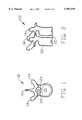
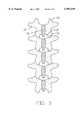
- FIGS. 1, 2, and 3top, side, and posterior views of a vertebral body, a pair of adjacent vertebral bodies, and a sequence of vertebral bodies are shown, respectively.
- the spinal cordis housed in the central canal 10, protected from the posterior side by a shell of bone called the lamina 12.
- the lamina 12includes a rearwardly and downwardly extending portion called the spinous process 16, and laterally extending structures which are referred to as the transverse processes 14.
- the anterior portion of the spinecomprises a set of generally cylindrically shaped bones which are stacked one on top of the other. These portions of the vertebrae are referred to as the vertebral bodies 20, and are each separated from the other by the intervertebral discs 22.
- the pedicles 24comprise bone bridges which couple the anterior vertebral body 20 to the corresponding lamina 12.
- the spinal column of bonesis highly complex in that it includes over twenty bones coupled to one another, housing and protecting critical elements of the nervous system having innumerable peripheral nerves and circulatory bodies in close proximity.
- the spineis a highly flexible structure, capable of a high degree of curvature and twist in nearly every direction. Genetic or developmental irregularities, trauma, chronic stress, tumors, and disease, however, can result in spinal pathologies which either limit this range of motion, or which threaten the critical elements of the nervous system housed within the spinal column.
- a variety of systemshave been disclosed in the art which achieve this immobilization by implanting artificial assemblies in or on the spinal column. These assemblies may be classified as anterior, posterior, or lateral implants.
- Posterior implantsgenerally comprise pairs of rods, which are aligned along the axis along which the bones are to be disposed, and which are then attached to the spinal column by either hooks which couple to the lamina or attach to the transverse processes, or by screws which are inserted through the pedicles.
- Rod assembliesgenerally comprise a plurality of such screws which are implanted through the posterior lateral surfaces of the laminae, through the pedicles, and into their respective vertebral bodies.
- the screwsare provided with upper portions which comprise, or have mounted thereto, coupling elements for receiving and securing an elongate rod therethrough.
- the rodextends along the axis of the spine, coupling to the plurality of screws via their coupling elements.
- the rigidity of the rodmay be utilized to align the spine in conformance with a more desired shape.
- the principal object of the present inventionto provide a pedicle screw and coupling element assembly which provides a polyaxial freedom of implantation angulation with respect to rod reception.
- the present inventionis a pedicle screw and rod coupling mechanism having a polyaxially rotating screw head which is selectively lockable at a desired fixed position with a cross-bar rod coupling mechanism as it is secured to the head.
- the present inventioncomprises a bone screw having a semi-spherical ball top.
- the shaft of the screwis threaded for insertion and secure retention in vertebral bone.
- the ball-shaped tophas a constant radius of curvature over the curvate portion thereof, which forms a ball top end of the screw, and includes a recess therein so that it may be driven by a screw driving mechanism into the pedicular bone.
- Onto the ball top of the screwis mounted a polyaxial head member, which is initially polyaxially disposed on the ball top of the screw.
- the polyaxial head membercomprises a flattened teardrop-shaped member having a truncated acute end which includes a lower socket portion, and a through hole formed in the bulbous upper central portion.
- the polyaxial head memberfurther includes a vertical split which extends upwardly from the lower socket portion, past the upper central portion which includes the through hole. The vertical split extends fully through the lower socket portion, but not fully through the upper portion so that the member is a single piece. This split divides the head member along a plane which is substantially parallel to the front and rear flat faces thereof.
- the plane of the slotmay have a slight angle as compared with the front face, extending slightly rearward as it rises.
- the overall front-to-rear thickness of the polyaxial head memberinclude a very slight taper such that the member is thicker at the base than at the top thereof.
- the slot in the memberdivides the through hole into a front portion and a rear portion.
- the front portionincludes a linear taper such that the opening is wider at the face and narrows as it approaches the vertical slot.
- the polyaxial head memberis designed to receive the ball top of the screw into the socket, the socket having substantially the same interior volume as necessary to permit the ball top to loosely rotate in the socket.
- at least a portion of the socketis further split into two halves by the vertical slot. This slot renders the socket compressible (the deflection of the slot in a narrowing direction causes a decrease in the total volume of the socket, permitting the interior surface to crush lock to the ball top of the screw in the socket.
- the means by which the slots are deflected and the socket volume reducedis described more fully hereinbelow).
- the rod gripping cross-bar member of the present inventioncomprises a cylindrical member having a threaded second end, a tapered middle portion, and a first end comprising a pair of opposing arcuate gripping jaw elements. More particularly, with respect to the threaded portion, the second end comprises a constant diameter cylinder that has a diameter wich is substantially similar to the constant diameter rear portion of the through hole in the polyaxial head member.
- the tapered middle portionhas a linear tapered surface which widens from the point at which it is contiguous with the threaded end to the point at which it joins with the rod gripping first end. This linear taper has substantially the same angle of taper as the front portion of the through hole in the polyaxial head member.
- the first end of the cross-bar memberwhich grips the rod, comprises a pair of arcuate opposing members, the inner opposing surfaces of which comprise a cylindrical receiving volume.
- the cross-bar memberfurther comprises an axial split extending from the middle of the second end, through the tapered middle portion, and fully through the first end (between the opposing arcuate jaw members,) thereby rendering the inner opposing arcuate surfaces of the rod gripping end selectively deflectable into a wider or narrower position by the application of forces directed radially outward or inward on the axial slot.
- the total combined angle of the partial circular cross-section of the opposing jawsis greater than 180 degrees in the undeflected state, so as to permit a rod of similar diameter to be received laterally into the receiving volume only when the jaws are deflected into the widened position, and for the rod to be crush locked in the jaws by the application of an inwardly directed radial force.
- the assembly and implantation of the present inventionis now briefly described.
- the surgeonprepares the pedicle site for receiving the shaft of the screw and drives the screw into the bone.
- the cross-bar memberis positioned loosely in the through holes such that the second threaded end extends through the rear portion of the through hole and the tapered middle portion is seated in the front tapered portion of the through hole.
- the polyaxial headis then mounted to the ball top of the screw (by permitting the vertical slot in the head to widen as the ball is inserted into the socket). At this time the head member is fully polyaxially rotatable on the ball top of the screw. Once the head has been properly positioned, the cross-bar member is axially rotated into position to receive the rod of the implant apparatus in its jaws.
- the rodis inserted into the cylindrical receiving volume formed by the opposing jaw members of the cross-bar element.
- a nutis then engaged onto the threading of the second end of the cross bar member and advanced therealong until it contacts the rear face of the polyaxial head member (the lower portion of the rear face should be contacted first in the preferred design which has a widened base of the head member). Once the nut has contacted the rear face, continued tightening causes the cross-bar member to be drawn toward the rear face, through the through hole, until the tapered middle portion of the cross bar is fully and tightly nested in the front portion of the through hole.
- screw and coupling element assembly of the present inventionis designed to be compatible with alternative rod systems so that, where necessary, the present invention may be employed to rectify the failures of other systems, the implantation of which may have already begun.
- FIG. 1is a top view of a human vertebra, which is representative of the type for which the present invention is useful for coupling thereto a rod apparatus;
- FIG. 2is a side view of a pair of adjacent vertebrae of the type shown in FIG. 1;
- FIG. 3is a posterior view of a sequence of vertebrae of the type shown in FIGS. 1 and 2;
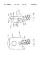
- FIG. 4is a side view of a bone screw having a ball top which is an aspect of the present invention.
- FIGS. 5a and 5bare side views of a first embodiment of the polyaxial head member of the present invention mounted to the ball top of the pedicle screw illustrated in FIG. 4, wherein critical interior features of the element are shown in phantom and wherein the side views are taken along mutually perpendicular directions showing the front face and the left lateral side of the polyaxial head member respectively;
- FIGS. 6a and 6bare side views of the cross-bar member of the present invention, wherein the side views are taken along mutually perpendicular directions;
- FIG. 7is a top perspective view of the nut which is an aspect of the present invention.
- FIG. 8is a side view of a fully assembled embodiment of the present invention.
- FIG. 4a side view of the screw portion of the present invention, comprising a curvate ball top, is shown.
- the screw 120comprises a ball top portion 122, a neck 124, and a shaft 126.
- the shaft 126is shown as having a tapered shape with a high pitch thread 128. It shall be understood that a variety of shaft designs are interchangeable with the present design. The specific choice of shaft features, such as thread pitch, shaft diameter to thread diameter ratio, and overall shaft shape, should be made by the physician with respect to the conditions of the individual patient's bone; however, this invention is compatible with a wide variety of shaft designs.
- the ball top 122 of the screw 120comprises a semi-spherical shape, which has a recess 130 in it. It is understood that the semi-spherical shape is a section of a sphere. In the embodiment shown the section is greater in extent than a hemisphere, and it correspondingly exhibits an external contour which is equidistant from a center point of the ball top.
- the major cross-section of the semi-spherical ball top 122(as shown in the two-dimensional illustration of FIG. 4) includes at least 270 degrees of a circle.
- the recess 130defines a receiving locus for the application of a torque for driving the screw 120 into the bone.
- the specific shape of the recess 122may be chosen to cooperate with any suitable screw-driving tool.
- the recess 130may comprise a slot for a screwdriver, a hexagonally shaped hole for receiving an allen wrench, or most preferably, a threading for a correspondingly threaded post.
- the recess 130be co-axial with the general elongate axis of the screw 120, and most particularly with respect to the shaft 126. Having the axes of the recess 130 and the shaft 126 co-linear facilitates the step of inserting the screw 120 into the bone.
- the semi-spherical ball top portion 122is connected to the shaft 126 at a neck portion 124. While it is preferable that the diameter of the shaft 126 be less than the diameter of the semi-spherical ball top 122, it is also preferable that the neck 124 of the screw 120 be narrower than the widest portion of the shaft 126. This preferable dimension permits the screw to swing through a variety of angles while still being securely held in the socket of the polyaxial head member (as set forth more fully with respect to FIGS. 5a and 5b).
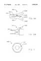
- a first embodiment of the polyaxial head member 200 of the present inventionis provided in front and lateral side views, respectively, in its initially polyaxial mounted position on the ball top 122 of the screw 120. More specifically with respect to the front view shown in FIG. 5a, the element 200 may be conceptually separated into a lower socket portion 202 and an upper cross-bar member receiving portion 204.
- the lower socket portion 202comprises a semi-spherical interior volume 206. This interior volume 206 is accessible from the exterior through a bottom opening 208.
- the ball top 122 of the screw 120is insertable into the socket 206, and is initially polyaxially rotatable within the socket through a wide range of angles which are limited only by the contact of the neck 124 of the screw against the lip 210 of the opening 208 (the diameter of the neck 124 necessarily being less than that of the opening 208).
- the upper portion 204 of the polyaxial head element 200comprises a vertical split or slot 212 which extends upwardly from the lower socket portion 202 (rendering the socket expandable and contractible), and terminates at a point 214 which is adjacent to, but below the extreme uppermost point of the head 200.
- the headfurther includes a through hole 216a,216b which is separated into a front portion 216a and a rear portion 216b by the vertical slot 212.
- the vertical slot 212extends upward through the head 200 at a slight rearward angle.
- the overall front-to-rear thickness of the polyaxial head member 200include a very slight taper (the plane of the rear face forms a non-perpendicular angle with the axis of the through hole 216a,216b such that the lower portion of the rear face 217b forms an acute angle relative to the axis of the through hole). The purpose of this taper and the rearward angulation of the slot is to ensure that the slot 212 may be most effectively narrowed by the application of a compression force against the front and rear faces of the head member 200.
- the slot 212 in the member 200divides the through hole into a front portion 216a and a rear portion 216b.
- the front portion 216ais linearly tapered along the axial direction, such that the opening 218 is wider at the front face 217a and narrows as it approaches the plane of the vertical slot 212.
- the rod gripping cross-bar member 220 of the present inventionis provided in lateral side and top side views, respectively.
- the rod gripping member 220comprises a cylindrical member having a first end 222 comprising a pair of opposing arcuate gripping jaw elements 224a,224b which together form a rod receiving channel 225; a threaded second end 226, a tapered middle portion 228. More particularly, with respect to the threaded portion 226; the second end comprises a constant diameter cylinder which has a diameter that is substantially similar to the constant-diameter rear portion 216b of the through hole in the polyaxial head member 200.
- the tapered middle portion 228has a surface 230 which comprises the linear taper which widens from the point at which it is contiguous with the threaded end 226 to the point at which it joins with the rod gripping first end 222.
- This linear tapered surface 230has substantially the same angle of taper as the front portion 216a of the through hole in the polyaxial head member 200.
- first end 222 of the cross-bar memberwhich grips the rod, comprises a pair of arcuate opposing members 224a,224b, the inner opposing surfaces of which comprise a cylindrical receiving volume 225.
- the cross-bar memberfurther comprises an axial split 232 extending from the middle of the second end 226, through the tapered middle portion 228, and fully through the first end 222 between the opposing arcuate jaw members 224a,224b, thereby providing the means by which the inner opposing arcuate surfaces 234a,234b of the rod gripping end may deflect to widen or narrow the size of the rod receiving channel 225 by the application of forces directed radially outward or inward, respectively, on the axial slot 232.
- the total combined angle of the partial circular cross-section of the opposing jaws 224a,224bis greater than 180 degrees in the undeflected state, thus permitting a rod of similar diameter to laterally enter the receiving volume only when the jaws 224a,224b are deflected into the widened position, and for the rod to be crush locked to the inner surfaces 234a,234b of the jaws by the application of an inwardly directed radial force.
- the nut 240which is provided to advance along the threaded second end 226 of the rod gripping member 220 is provided.
- the nut 240is a standard nut having a hexagonal-shaped outer rim 242 and a threaded center bore 244 which is designed to receive therethrough the second end 226 of the rod gripping member 220. As set forth hereinbelow, it is the advancement of the nut 240 along this threaded second end 220 which provides the necessary forces to lock the assembly together.
- FIG. 8in which a fully locked and assembled embodiment of the present invention is provided, the assembly and implantation of the present invention is now described.
- the surgeonprepares the pedicle site for receiving the shaft of the screw 120 and drives the screw into the bone.
- the rod gripping cross-bar member 220is positioned loosely in the through holes 216a,216b such that the second threaded end 226 extends through the rear portion 216b of the through hole and the tapered middle portion 228 is seated in the front tapered portion 216a of the through hole.
- the polyaxial head 200is then mounted to the ball top 122 of the screw (by permitting the vertical slot 212 in the head 200 to widen as the ball 212 is inserted into the socket 202). At this time the head member is fully polyaxially rotatable on the ball top of the screw.
- the cross-bar member 220is axially rotated into position to receive the rod 250 of the implant apparatus laterally between its jaws 224a,224b.
- the rod 250is inserted into the cylindrical receiving volume 225 formed by the opposing jaw members of the cross-bar element 220.
- a nut 240is then engaged onto the threading of the second end 226 of the cross-bar member and advanced therealong until it contacts the rear face 217b of the polyaxial head member 220 (the lower portion of the rear face should be contacted first in the preferred design which has a widened base of the head member).
- the compression of the axial slot 232is provided by radially inward directed forces developed by the mutual engagement of the tapers of the middle tapered section 228 of the rod gripping cross-bar member 220 and the front portion 216a of the through hole. These slot compressions simultaneously lock the head 200 to the ball top 122 of the screw 120, the rod gripping cross-bar member 220 in the through hole 216a,216b of the polyaxial head member 200, and the rod 250 in the jaws 224a,224b of the cross-bar member 220.
Landscapes
- Health & Medical Sciences (AREA)
- Orthopedic Medicine & Surgery (AREA)
- Life Sciences & Earth Sciences (AREA)
- Neurology (AREA)
- Surgery (AREA)
- Heart & Thoracic Surgery (AREA)
- Engineering & Computer Science (AREA)
- Biomedical Technology (AREA)
- Nuclear Medicine, Radiotherapy & Molecular Imaging (AREA)
- Medical Informatics (AREA)
- Molecular Biology (AREA)
- Animal Behavior & Ethology (AREA)
- General Health & Medical Sciences (AREA)
- Public Health (AREA)
- Veterinary Medicine (AREA)
- Surgical Instruments (AREA)
Abstract
Description
Claims (20)
Priority Applications (1)
| Application Number | Priority Date | Filing Date | Title |
|---|---|---|---|
| US09/070,268US5997539A (en) | 1997-05-15 | 1998-04-30 | Polyaxial pedicle screw having a compression locking rod gripping mechanism |
Applications Claiming Priority (3)
| Application Number | Priority Date | Filing Date | Title |
|---|---|---|---|
| US08/856,773US5785711A (en) | 1997-05-15 | 1997-05-15 | Polyaxial pedicle screw having a through bar clamp locking mechanism |
| US08/880,810US5810819A (en) | 1997-05-15 | 1997-06-23 | Polyaxial pedicle screw having a compression locking rod gripping mechanism |
| US09/070,268US5997539A (en) | 1997-05-15 | 1998-04-30 | Polyaxial pedicle screw having a compression locking rod gripping mechanism |
Related Parent Applications (1)
| Application Number | Title | Priority Date | Filing Date |
|---|---|---|---|
| US08/880,810ContinuationUS5810819A (en) | 1997-05-15 | 1997-06-23 | Polyaxial pedicle screw having a compression locking rod gripping mechanism |
Publications (1)
| Publication Number | Publication Date |
|---|---|
| US5997539Atrue US5997539A (en) | 1999-12-07 |
Family
ID=27127376
Family Applications (2)
| Application Number | Title | Priority Date | Filing Date |
|---|---|---|---|
| US08/880,810Expired - LifetimeUS5810819A (en) | 1997-05-15 | 1997-06-23 | Polyaxial pedicle screw having a compression locking rod gripping mechanism |
| US09/070,268Expired - LifetimeUS5997539A (en) | 1997-05-15 | 1998-04-30 | Polyaxial pedicle screw having a compression locking rod gripping mechanism |
Family Applications Before (1)
| Application Number | Title | Priority Date | Filing Date |
|---|---|---|---|
| US08/880,810Expired - LifetimeUS5810819A (en) | 1997-05-15 | 1997-06-23 | Polyaxial pedicle screw having a compression locking rod gripping mechanism |
Country Status (1)
| Country | Link |
|---|---|
| US (2) | US5810819A (en) |
Cited By (159)
| Publication number | Priority date | Publication date | Assignee | Title |
|---|---|---|---|---|
| US6187005B1 (en)* | 1998-09-11 | 2001-02-13 | Synthes (Usa) | Variable angle spinal fixation system |
| US6261291B1 (en) | 1999-07-08 | 2001-07-17 | David J. Talaber | Orthopedic implant assembly |
| US6368320B1 (en)* | 1997-12-09 | 2002-04-09 | (Dimso) Distribution Medicale Du Sud-Ouest | Connector for backbone osteosynthesis device |
| WO2002022030A3 (en)* | 2000-09-15 | 2002-09-06 | Sdgi Holdings Inc | Posterior fixation system |
| US20020147453A1 (en)* | 2001-04-04 | 2002-10-10 | Jordan Medical Llc | Implantable bone fracture reduction apparatus having a polymeric applicator |
| US6482207B1 (en)* | 2000-07-13 | 2002-11-19 | Fastenetix, Llc | Efficient assembling modular locking pedicle screw |
| US20030055426A1 (en)* | 2001-09-14 | 2003-03-20 | John Carbone | Biased angulation bone fixation assembly |
| US6565566B1 (en) | 2000-03-22 | 2003-05-20 | Spinal Concepts, Inc. | Sacral screw assembly and method |
| US6626906B1 (en) | 2000-10-23 | 2003-09-30 | Sdgi Holdings, Inc. | Multi-planar adjustable connector |
| US20040030337A1 (en)* | 2002-04-09 | 2004-02-12 | Neville Alleyne | Bone fixation apparatus |
| US20040065680A1 (en)* | 2001-09-24 | 2004-04-08 | Schroeder Alfred A. | Beverage dispensing with cold carbonation |
| US6736816B2 (en) | 2000-06-30 | 2004-05-18 | Stephen Ritland | Polyaxial connection device and method |
| US6770075B2 (en) | 2001-05-17 | 2004-08-03 | Robert S. Howland | Spinal fixation apparatus with enhanced axial support and methods for use |
| US20040153077A1 (en)* | 2000-11-10 | 2004-08-05 | Lutz Biedermann | Bone screw |
| US20040181223A1 (en)* | 2001-09-28 | 2004-09-16 | Stephen Ritland | Adjustable rod and connector device and method of use |
| US20040193166A1 (en)* | 2002-10-11 | 2004-09-30 | Spineco Inc., An Ohio Corporation | Electro-stimulation and medical delivery device |
| US20040243130A1 (en)* | 2002-10-11 | 2004-12-02 | Spineco, Inc., An Ohio Corporation | Electro-stimulation and medical delivery device |
| US20050080419A1 (en)* | 2002-02-11 | 2005-04-14 | Synthes U.S.A. | Device for connecting a longitudinal member to a bone |
| US20050096653A1 (en)* | 2003-11-03 | 2005-05-05 | Doubler Robert L. | Bone fixation system with low profile fastener |
| US20050154391A1 (en)* | 2003-12-30 | 2005-07-14 | Thomas Doherty | Bone anchor assemblies |
| US20050154393A1 (en)* | 2003-12-30 | 2005-07-14 | Thomas Doherty | Bone anchor assemblies and methods of manufacturing bone anchor assemblies |
| US20050187548A1 (en)* | 2004-01-13 | 2005-08-25 | Butler Michael S. | Pedicle screw constructs for spine fixation systems |
| US20050209698A1 (en)* | 2003-08-05 | 2005-09-22 | Gordon Charles R | Expandable intervertebral implant |
| US20050240181A1 (en)* | 2004-04-23 | 2005-10-27 | Boomer Mark C | Spinal implant connectors |
| US6966910B2 (en) | 2002-04-05 | 2005-11-22 | Stephen Ritland | Dynamic fixation device and method of use |
| US20060036253A1 (en)* | 2004-04-20 | 2006-02-16 | Spineco, Inc. | Implant device |
| US20060195096A1 (en)* | 2005-02-09 | 2006-08-31 | David Lee | Bone fixation apparatus |
| AU2004202174B2 (en)* | 2000-09-15 | 2006-10-12 | Warsaw Orthopedic, Inc. | Posterior fixation system |
| US20060229729A1 (en)* | 2003-08-05 | 2006-10-12 | Gordon Charles R | Expandable intervertebral implant for use with instrument |
| US20060241591A1 (en)* | 2005-04-25 | 2006-10-26 | Spineco, Inc. | Vertebral pars interarticularis clamp a new spine fixation device, instrumentation, and methodology |
| US20060241771A1 (en)* | 2003-08-05 | 2006-10-26 | Southwest Research Institute | Artificial functional spinal unit system and method for use |
| US20060247626A1 (en)* | 2005-04-29 | 2006-11-02 | Sdgi Holdings, Inc. | Device for interconnecting components in spinal instrumentation |
| US7141051B2 (en) | 2003-02-05 | 2006-11-28 | Pioneer Laboratories, Inc. | Low profile spinal fixation system |
| US7166073B2 (en) | 2000-09-29 | 2007-01-23 | Stephen Ritland | Method and device for microsurgical intermuscular spinal surgery |
| US7204853B2 (en) | 2003-08-05 | 2007-04-17 | Flexuspine, Inc. | Artificial functional spinal unit assemblies |
| US7207992B2 (en) | 2001-09-28 | 2007-04-24 | Stephen Ritland | Connection rod for screw or hook polyaxial system and method of use |
| US7214186B2 (en) | 2000-09-29 | 2007-05-08 | Stephen Ritland | Method and device for retractor for microsurgical intermuscular lumbar arthrodesis |
| US20070225711A1 (en)* | 2006-03-22 | 2007-09-27 | Ensign Michael D | Low top bone fixation system and method for using the same |
| US20070233072A1 (en)* | 2006-03-01 | 2007-10-04 | Sdgi Holdings, Inc. | Modular fastener assemblies for spinal stabilization systems and methods |
| US7314467B2 (en) | 2002-04-24 | 2008-01-01 | Medical Device Advisory Development Group, Llc. | Multi selective axis spinal fixation system |
| US20080004626A1 (en)* | 2006-05-26 | 2008-01-03 | Glazer Paul A | Orthopedic coil screw insert |
| US7316714B2 (en) | 2003-08-05 | 2008-01-08 | Flexuspine, Inc. | Artificial functional spinal unit assemblies |
| US20080015576A1 (en)* | 2006-04-28 | 2008-01-17 | Whipple Dale E | Large diameter bone anchor assembly |
| US20080045955A1 (en)* | 2006-08-16 | 2008-02-21 | Berrevoets Gregory A | Spinal Rod Anchor Device and Method |
| US20080065085A1 (en)* | 2002-08-23 | 2008-03-13 | Orthosoft Inc. | Surgical universal positioning block and tool guide |
| US20080183220A1 (en)* | 2007-01-19 | 2008-07-31 | Glazer Paul A | Orthopedic screw insert |
| US7455639B2 (en) | 2004-09-20 | 2008-11-25 | Stephen Ritland | Opposing parallel bladed retractor and method of use |
| US20090105828A1 (en)* | 2007-10-22 | 2009-04-23 | Gimbel Jonathan A | Posterior stabilization system with isolated, dual dampener systems |
| US20090105757A1 (en)* | 2007-10-22 | 2009-04-23 | Gimbel Jonathan A | Posterior stabilization systems with shared, dual dampener systems |
| US20090105759A1 (en)* | 2007-10-22 | 2009-04-23 | Gimbel Jonathan A | Spinal stabilization systems with dynamic interbody devices |
| US20090105770A1 (en)* | 2007-10-23 | 2009-04-23 | Gregory Berrevoets | Rod Coupling Assembly and Methods for Bone Fixation |
| US20090105758A1 (en)* | 2007-10-22 | 2009-04-23 | Gimbel Jonathan A | Dampener system for a posterior stabilization system with a variable length elongated member |
| EP1545353A4 (en)* | 2002-02-20 | 2009-06-24 | Stephen Ritland | Pedicle screw connector apparatus and method |
| US20090254125A1 (en)* | 2008-04-03 | 2009-10-08 | Daniel Predick | Top Loading Polyaxial Spine Screw Assembly With One Step Lockup |
| US7628799B2 (en) | 2005-08-23 | 2009-12-08 | Aesculap Ag & Co. Kg | Rod to rod connector |
| US20090318973A1 (en)* | 2006-05-30 | 2009-12-24 | Jean-Pierre Moulin | Bone fixing device |
| US20100049253A1 (en)* | 2008-08-20 | 2010-02-25 | Warsaw Orthopedic, Inc. | Bottom loading connector for attaching a spinal rod to a vertebral member |
| US7682375B2 (en) | 2002-05-08 | 2010-03-23 | Stephen Ritland | Dynamic fixation device and method of use |
| US20100094349A1 (en)* | 2004-08-27 | 2010-04-15 | Michael Hammer | Multi-Axial Connection System |
| US7736380B2 (en) | 2004-12-21 | 2010-06-15 | Rhausler, Inc. | Cervical plate system |
| US7744633B2 (en) | 2003-10-22 | 2010-06-29 | Pioneer Surgical Technology, Inc. | Crosslink for securing spinal rods |
| US7744632B2 (en) | 2006-12-20 | 2010-06-29 | Aesculap Implant Systems, Inc. | Rod to rod connector |
| US7766945B2 (en) | 2004-08-10 | 2010-08-03 | Lanx, Inc. | Screw and rod fixation system |
| US20100211100A1 (en)* | 2009-02-19 | 2010-08-19 | Mack Claudia | Apparatus for spinal-column stabilization |
| US20100222822A1 (en)* | 2002-08-28 | 2010-09-02 | Warsaw Orthopedic, Inc. | Posterior Fixation System |
| US20100256681A1 (en)* | 2004-08-27 | 2010-10-07 | Hammer Michael A | Multi-axial connection system |
| US7842071B2 (en) | 2006-07-11 | 2010-11-30 | Pioneer Surgical Technology, Inc. | Transverse connector |
| US7896902B2 (en) | 2006-04-05 | 2011-03-01 | Dong Myung Jeon | Multi-axial double locking bone screw assembly |
| US7909869B2 (en) | 2003-08-05 | 2011-03-22 | Flexuspine, Inc. | Artificial spinal unit assemblies |
| US7955363B2 (en) | 2002-04-18 | 2011-06-07 | Aesculap Implant Systems, Llc | Screw and rod fixation assembly and device |
| US20110137416A1 (en)* | 2009-03-31 | 2011-06-09 | Thomas H. Myers | Double bundle acl repair |
| US7959677B2 (en) | 2007-01-19 | 2011-06-14 | Flexuspine, Inc. | Artificial functional spinal unit system and method for use |
| US7959564B2 (en) | 2006-07-08 | 2011-06-14 | Stephen Ritland | Pedicle seeker and retractor, and methods of use |
| US20110178552A1 (en)* | 2005-04-25 | 2011-07-21 | Spineco, Inc. | Vertebral pars interarticularis clamp a new spine fixation device, instrumentation, and methodology |
| US8021399B2 (en) | 2005-07-19 | 2011-09-20 | Stephen Ritland | Rod extension for extending fusion construct |
| US8070785B2 (en) | 2003-09-16 | 2011-12-06 | Spineco, Inc. | Bone anchor prosthesis and system |
| US8118837B2 (en)* | 2008-07-03 | 2012-02-21 | Zimmer Spine, Inc. | Tapered-lock spinal rod connectors and methods for use |
| US8118869B2 (en) | 2006-03-08 | 2012-02-21 | Flexuspine, Inc. | Dynamic interbody device |
| US20120059469A1 (en)* | 2009-03-31 | 2012-03-08 | Medicinelodge, Inc. Dba Imds Co-Innovation | Double bundle acl repair system |
| US8133262B2 (en) | 2006-04-28 | 2012-03-13 | Depuy Spine, Inc. | Large diameter bone anchor assembly |
| US8157844B2 (en) | 2007-10-22 | 2012-04-17 | Flexuspine, Inc. | Dampener system for a posterior stabilization system with a variable length elongated member |
| US8167914B1 (en) | 2008-07-16 | 2012-05-01 | Zimmer Spine, Inc. | Locking insert for spine stabilization and method of use |
| US8182514B2 (en) | 2007-10-22 | 2012-05-22 | Flexuspine, Inc. | Dampener system for a posterior stabilization system with a fixed length elongated member |
| US8197512B1 (en)* | 2008-07-16 | 2012-06-12 | Zimmer Spine, Inc. | System and method for spine stabilization using resilient inserts |
| US8197517B1 (en) | 2007-05-08 | 2012-06-12 | Theken Spine, Llc | Frictional polyaxial screw assembly |
| US8262571B2 (en) | 2003-05-22 | 2012-09-11 | Stephen Ritland | Intermuscular guide for retractor insertion and method of use |
| US20120303070A1 (en)* | 2005-09-30 | 2012-11-29 | Jackson Roger P | Polyaxial bone anchor assembly with one-piece closure, pressure insert and plastic elongate member |
| US8328807B2 (en) | 2008-07-09 | 2012-12-11 | Icon Orthopaedic Concepts, Llc | Ankle arthrodesis nail and outrigger assembly |
| US8361129B2 (en) | 2006-04-28 | 2013-01-29 | Depuy Spine, Inc. | Large diameter bone anchor assembly |
| US8361123B2 (en) | 2009-10-16 | 2013-01-29 | Depuy Spine, Inc. | Bone anchor assemblies and methods of manufacturing and use thereof |
| US8388660B1 (en) | 2006-08-01 | 2013-03-05 | Samy Abdou | Devices and methods for superior fixation of orthopedic devices onto the vertebral column |
| US8414584B2 (en) | 2008-07-09 | 2013-04-09 | Icon Orthopaedic Concepts, Llc | Ankle arthrodesis nail and outrigger assembly |
| US8506601B2 (en) | 2008-10-14 | 2013-08-13 | Pioneer Surgical Technology, Inc. | Low profile dual locking fixation system and offset anchor member |
| US8636778B2 (en) | 2009-02-11 | 2014-01-28 | Pioneer Surgical Technology, Inc. | Wide angulation coupling members for bone fixation system |
| US8771319B2 (en) | 2012-04-16 | 2014-07-08 | Aesculap Implant Systems, Llc | Rod to rod cross connector |
| US8828056B2 (en) | 2012-04-16 | 2014-09-09 | Aesculap Implant Systems, Llc | Rod to rod cross connector |
| US8852239B2 (en) | 2013-02-15 | 2014-10-07 | Roger P Jackson | Sagittal angle screw with integral shank and receiver |
| US8870928B2 (en) | 2002-09-06 | 2014-10-28 | Roger P. Jackson | Helical guide and advancement flange with radially loaded lip |
| US8911478B2 (en) | 2012-11-21 | 2014-12-16 | Roger P. Jackson | Splay control closure for open bone anchor |
| US8926672B2 (en) | 2004-11-10 | 2015-01-06 | Roger P. Jackson | Splay control closure for open bone anchor |
| US8926670B2 (en) | 2003-06-18 | 2015-01-06 | Roger P. Jackson | Polyaxial bone screw assembly |
| US8940051B2 (en) | 2011-03-25 | 2015-01-27 | Flexuspine, Inc. | Interbody device insertion systems and methods |
| US8940020B2 (en) | 2012-04-06 | 2015-01-27 | DePuy Synthes Products, LLC | Rod connector |
| US8968402B2 (en) | 2011-10-18 | 2015-03-03 | Arthrocare Corporation | ACL implants, instruments, and methods |
| US8998959B2 (en) | 2009-06-15 | 2015-04-07 | Roger P Jackson | Polyaxial bone anchors with pop-on shank, fully constrained friction fit retainer and lock and release insert |
| US8998961B1 (en) | 2009-02-26 | 2015-04-07 | Lanx, Inc. | Spinal rod connector and methods |
| US8998960B2 (en) | 2004-11-10 | 2015-04-07 | Roger P. Jackson | Polyaxial bone screw with helically wound capture connection |
| US9084634B1 (en) | 2010-07-09 | 2015-07-21 | Theken Spine, Llc | Uniplanar screw |
| US9144444B2 (en) | 2003-06-18 | 2015-09-29 | Roger P Jackson | Polyaxial bone anchor with helical capture connection, insert and dual locking assembly |
| US9155580B2 (en) | 2011-08-25 | 2015-10-13 | Medos International Sarl | Multi-threaded cannulated bone anchors |
| US9168069B2 (en) | 2009-06-15 | 2015-10-27 | Roger P. Jackson | Polyaxial bone anchor with pop-on shank and winged insert with lower skirt for engaging a friction fit retainer |
| US9220541B1 (en) | 2014-06-26 | 2015-12-29 | Zimmer Spine, Inc. | Transverse connector |
| US9265548B2 (en) | 2008-10-30 | 2016-02-23 | DePuy Synthes Products, Inc. | Systems and methods for delivering bone cement to a bone anchor |
| US9308027B2 (en) | 2005-05-27 | 2016-04-12 | Roger P Jackson | Polyaxial bone screw with shank articulation pressure insert and method |
| US9339305B2 (en) | 2011-09-19 | 2016-05-17 | DePuy Synthes Products, Inc. | Snap fit rod and fastener system |
| US9393047B2 (en) | 2009-06-15 | 2016-07-19 | Roger P. Jackson | Polyaxial bone anchor with pop-on shank and friction fit retainer with low profile edge lock |
| US9405975B2 (en) | 2010-03-26 | 2016-08-02 | Brain Corporation | Apparatus and methods for pulse-code invariant object recognition |
| US9412041B1 (en) | 2012-06-29 | 2016-08-09 | Brain Corporation | Retinal apparatus and methods |
| US9436909B2 (en) | 2013-06-19 | 2016-09-06 | Brain Corporation | Increased dynamic range artificial neuron network apparatus and methods |
| US9439683B2 (en) | 2007-01-26 | 2016-09-13 | Roger P Jackson | Dynamic stabilization member with molded connection |
| US9451993B2 (en) | 2014-01-09 | 2016-09-27 | Roger P. Jackson | Bi-radial pop-on cervical bone anchor |
| US9489623B1 (en) | 2013-10-15 | 2016-11-08 | Brain Corporation | Apparatus and methods for backward propagation of errors in a spiking neuron network |
| US9492288B2 (en) | 2013-02-20 | 2016-11-15 | Flexuspine, Inc. | Expandable fusion device for positioning between adjacent vertebral bodies |
| US9504496B2 (en) | 2009-06-15 | 2016-11-29 | Roger P. Jackson | Polyaxial bone anchor with pop-on shank, friction fit retainer and winged insert |
| US9517144B2 (en) | 2014-04-24 | 2016-12-13 | Exactech, Inc. | Limited profile intervertebral implant with incorporated fastening mechanism |
| US9526627B2 (en) | 2011-11-17 | 2016-12-27 | Exactech, Inc. | Expandable interbody device system and method |
| US9552546B1 (en) | 2013-07-30 | 2017-01-24 | Brain Corporation | Apparatus and methods for efficacy balancing in a spiking neuron network |
| US9566092B2 (en) | 2013-10-29 | 2017-02-14 | Roger P. Jackson | Cervical bone anchor with collet retainer and outer locking sleeve |
| US9597119B2 (en) | 2014-06-04 | 2017-03-21 | Roger P. Jackson | Polyaxial bone anchor with polymer sleeve |
| US9636146B2 (en) | 2012-01-10 | 2017-05-02 | Roger P. Jackson | Multi-start closures for open implants |
| US9662143B2 (en) | 2004-02-27 | 2017-05-30 | Roger P Jackson | Dynamic fixation assemblies with inner core and outer coil-like member |
| US9668771B2 (en) | 2009-06-15 | 2017-06-06 | Roger P Jackson | Soft stabilization assemblies with off-set connector |
| US9717533B2 (en) | 2013-12-12 | 2017-08-01 | Roger P. Jackson | Bone anchor closure pivot-splay control flange form guide and advancement structure |
| US9881349B1 (en) | 2014-10-24 | 2018-01-30 | Gopro, Inc. | Apparatus and methods for computerized object identification |
| US9907574B2 (en) | 2008-08-01 | 2018-03-06 | Roger P. Jackson | Polyaxial bone anchors with pop-on shank, friction fit fully restrained retainer, insert and tool receiving features |
| US9918745B2 (en) | 2009-06-15 | 2018-03-20 | Roger P. Jackson | Polyaxial bone anchor with pop-on shank and winged insert with friction fit compressive collet |
| US10058354B2 (en) | 2013-01-28 | 2018-08-28 | Roger P. Jackson | Pivotal bone anchor assembly with frictional shank head seating surfaces |
| US10064658B2 (en) | 2014-06-04 | 2018-09-04 | Roger P. Jackson | Polyaxial bone anchor with insert guides |
| US10278741B2 (en) | 2013-10-07 | 2019-05-07 | Spine Wave, Inc. | Translating polyaxial screw |
| US10349983B2 (en) | 2003-05-22 | 2019-07-16 | Alphatec Spine, Inc. | Pivotal bone anchor assembly with biased bushing for pre-lock friction fit |
| US10398565B2 (en) | 2014-04-24 | 2019-09-03 | Choice Spine, Llc | Limited profile intervertebral implant with incorporated fastening and locking mechanism |
| US10507043B1 (en) | 2017-10-11 | 2019-12-17 | Seaspine Orthopedics Corporation | Collet for a polyaxial screw assembly |
| US10543107B2 (en) | 2009-12-07 | 2020-01-28 | Samy Abdou | Devices and methods for minimally invasive spinal stabilization and instrumentation |
| US10548740B1 (en) | 2016-10-25 | 2020-02-04 | Samy Abdou | Devices and methods for vertebral bone realignment |
| US10575961B1 (en) | 2011-09-23 | 2020-03-03 | Samy Abdou | Spinal fixation devices and methods of use |
| US10603083B1 (en) | 2010-07-09 | 2020-03-31 | Theken Spine, Llc | Apparatus and method for limiting a range of angular positions of a screw |
| US10695105B2 (en) | 2012-08-28 | 2020-06-30 | Samy Abdou | Spinal fixation devices and methods of use |
| US10716596B2 (en) | 2017-10-10 | 2020-07-21 | Spine Wave, Inc. | Translational posterior cervical polyaxial screw |
| US10857003B1 (en) | 2015-10-14 | 2020-12-08 | Samy Abdou | Devices and methods for vertebral stabilization |
| US10918498B2 (en) | 2004-11-24 | 2021-02-16 | Samy Abdou | Devices and methods for inter-vertebral orthopedic device placement |
| US10973648B1 (en) | 2016-10-25 | 2021-04-13 | Samy Abdou | Devices and methods for vertebral bone realignment |
| US11006982B2 (en) | 2012-02-22 | 2021-05-18 | Samy Abdou | Spinous process fixation devices and methods of use |
| US11173040B2 (en) | 2012-10-22 | 2021-11-16 | Cogent Spine, LLC | Devices and methods for spinal stabilization and instrumentation |
| US11179248B2 (en) | 2018-10-02 | 2021-11-23 | Samy Abdou | Devices and methods for spinal implantation |
| US11229457B2 (en) | 2009-06-15 | 2022-01-25 | Roger P. Jackson | Pivotal bone anchor assembly with insert tool deployment |
| US11234745B2 (en) | 2005-07-14 | 2022-02-01 | Roger P. Jackson | Polyaxial bone screw assembly with partially spherical screw head and twist in place pressure insert |
| US12213704B1 (en) | 2024-06-18 | 2025-02-04 | Complex Spinal, LLC | Modular spinal fixation screw |
| US12245794B1 (en) | 2024-05-14 | 2025-03-11 | Complex Spinal, LLC | Spinal fixation system having a low profile lockable connector |
| US12245796B1 (en) | 2024-05-14 | 2025-03-11 | Complex Spinal, LLC | Spinal fixation system having a lockable connector |
Families Citing this family (66)
| Publication number | Priority date | Publication date | Assignee | Title |
|---|---|---|---|---|
| ES2191775T3 (en)* | 1996-12-12 | 2003-09-16 | Synthes Ag | DEVICE FOR CONNECTING A LONGITUDINAL SUPPORT WITH A PEDICULAR SCREW. |
| US6371957B1 (en) | 1997-01-22 | 2002-04-16 | Synthes (Usa) | Device for connecting a longitudinal bar to a pedicle screw |
| FR2762986B1 (en)* | 1997-05-07 | 1999-09-24 | Aesculap Jbs | OSTEOSYNTHESIS SYSTEM FOR VERTEBRAL ARTHRODESIS |
| US6248105B1 (en) | 1997-05-17 | 2001-06-19 | Synthes (U.S.A.) | Device for connecting a longitudinal support with a pedicle screw |
| US6033438A (en)* | 1997-06-03 | 2000-03-07 | Sdgi Holdings, Inc. | Open intervertebral spacer |
| US6258089B1 (en)* | 1998-05-19 | 2001-07-10 | Alphatec Manufacturing, Inc. | Anterior cervical plate and fixation system |
| US5910142A (en)* | 1998-10-19 | 1999-06-08 | Bones Consulting, Llc | Polyaxial pedicle screw having a rod clamping split ferrule coupling element |
| US6174311B1 (en)* | 1998-10-28 | 2001-01-16 | Sdgi Holdings, Inc. | Interbody fusion grafts and instrumentation |
| US6309391B1 (en) | 2000-03-15 | 2001-10-30 | Sdgi Holding, Inc. | Multidirectional pivoting bone screw and fixation system |
| US7322979B2 (en)* | 2000-03-15 | 2008-01-29 | Warsaw Orthopedic, Inc. | Multidirectional pivoting bone screw and fixation system |
| AU2001270790A1 (en)* | 2000-07-11 | 2002-01-21 | Dall Vagn-Erik | Gripping devices |
| US6551318B1 (en) | 2000-07-26 | 2003-04-22 | Stahurski Consulting Inc. | Spinal column retaining apparatus |
| JP2004505745A (en)* | 2000-08-24 | 2004-02-26 | ジンテーズ アクチエンゲゼルシャフト クール | Device for connecting a bone anchoring element to a longitudinal rod |
| US20050143737A1 (en)* | 2003-12-31 | 2005-06-30 | John Pafford | Dynamic spinal stabilization system |
| US8114158B2 (en) | 2004-08-03 | 2012-02-14 | Kspine, Inc. | Facet device and method |
| WO2006047555A2 (en)* | 2004-10-25 | 2006-05-04 | Alphaspine, Inc. | Bone fixation systems and methods |
| AU2006214001B2 (en) | 2005-02-18 | 2011-05-26 | Samy Abdou | Devices and methods for dynamic fixation of skeletal structure |
| WO2006096351A1 (en)* | 2005-03-03 | 2006-09-14 | Accelerated Innovation, Llc | Spinal stabilization using bone anchor and anchor seat with tangential locking feature |
| WO2006096381A2 (en)* | 2005-03-03 | 2006-09-14 | Accelerated Innovation Llc | Spinal stabilization using bone anchor seat and cross coupling with improved locking feature |
| US7927359B2 (en)* | 2005-10-06 | 2011-04-19 | Paradigm Spine, Llc | Polyaxial screw |
| US8057519B2 (en)* | 2006-01-27 | 2011-11-15 | Warsaw Orthopedic, Inc. | Multi-axial screw assembly |
| US7833252B2 (en)* | 2006-01-27 | 2010-11-16 | Warsaw Orthopedic, Inc. | Pivoting joints for spinal implants including designed resistance to motion and methods of use |
| US7722652B2 (en)* | 2006-01-27 | 2010-05-25 | Warsaw Orthopedic, Inc. | Pivoting joints for spinal implants including designed resistance to motion and methods of use |
| US20070191842A1 (en)* | 2006-01-30 | 2007-08-16 | Sdgi Holdings, Inc. | Spinal fixation devices and methods of use |
| US20080058808A1 (en) | 2006-06-14 | 2008-03-06 | Spartek Medical, Inc. | Implant system and method to treat degenerative disorders of the spine |
| US8043377B2 (en) | 2006-09-02 | 2011-10-25 | Osprey Biomedical, Inc. | Implantable intervertebral fusion device |
| US8021396B2 (en) | 2007-06-05 | 2011-09-20 | Spartek Medical, Inc. | Configurable dynamic spinal rod and method for dynamic stabilization of the spine |
| US8048123B2 (en) | 2007-06-05 | 2011-11-01 | Spartek Medical, Inc. | Spine implant with a deflection rod system and connecting linkages and method |
| US8048115B2 (en) | 2007-06-05 | 2011-11-01 | Spartek Medical, Inc. | Surgical tool and method for implantation of a dynamic bone anchor |
| US8052722B2 (en) | 2007-06-05 | 2011-11-08 | Spartek Medical, Inc. | Dual deflection rod system for a dynamic stabilization and motion preservation spinal implantation system and method |
| US8092501B2 (en) | 2007-06-05 | 2012-01-10 | Spartek Medical, Inc. | Dynamic spinal rod and method for dynamic stabilization of the spine |
| US8083772B2 (en) | 2007-06-05 | 2011-12-27 | Spartek Medical, Inc. | Dynamic spinal rod assembly and method for dynamic stabilization of the spine |
| US8109970B2 (en) | 2007-06-05 | 2012-02-07 | Spartek Medical, Inc. | Deflection rod system with a deflection contouring shield for a spine implant and method |
| US8048128B2 (en) | 2007-06-05 | 2011-11-01 | Spartek Medical, Inc. | Revision system and method for a dynamic stabilization and motion preservation spinal implantation system and method |
| US8114134B2 (en) | 2007-06-05 | 2012-02-14 | Spartek Medical, Inc. | Spinal prosthesis having a three bar linkage for motion preservation and dynamic stabilization of the spine |
| EP2155086B1 (en) | 2007-06-06 | 2016-05-04 | K2M, Inc. | Medical device to correct deformity |
| DE102007042959B4 (en)* | 2007-08-30 | 2011-03-31 | Aesculap Ag | Surgical retaining screw |
| DE102007042958B4 (en)* | 2007-08-30 | 2015-03-19 | Aesculap Ag | Surgical holding system |
| DE102007042953B4 (en)* | 2007-08-30 | 2015-01-22 | Aesculap Ag | Orthopedic retention system |
| US8048125B2 (en) | 2008-02-26 | 2011-11-01 | Spartek Medical, Inc. | Versatile offset polyaxial connector and method for dynamic stabilization of the spine |
| US8057517B2 (en) | 2008-02-26 | 2011-11-15 | Spartek Medical, Inc. | Load-sharing component having a deflectable post and centering spring and method for dynamic stabilization of the spine |
| US8211155B2 (en) | 2008-02-26 | 2012-07-03 | Spartek Medical, Inc. | Load-sharing bone anchor having a durable compliant member and method for dynamic stabilization of the spine |
| US8333792B2 (en) | 2008-02-26 | 2012-12-18 | Spartek Medical, Inc. | Load-sharing bone anchor having a deflectable post and method for dynamic stabilization of the spine |
| US8007518B2 (en) | 2008-02-26 | 2011-08-30 | Spartek Medical, Inc. | Load-sharing component having a deflectable post and method for dynamic stabilization of the spine |
| US8267979B2 (en) | 2008-02-26 | 2012-09-18 | Spartek Medical, Inc. | Load-sharing bone anchor having a deflectable post and axial spring and method for dynamic stabilization of the spine |
| US8337536B2 (en) | 2008-02-26 | 2012-12-25 | Spartek Medical, Inc. | Load-sharing bone anchor having a deflectable post with a compliant ring and method for stabilization of the spine |
| US8097024B2 (en) | 2008-02-26 | 2012-01-17 | Spartek Medical, Inc. | Load-sharing bone anchor having a deflectable post and method for stabilization of the spine |
| US8083775B2 (en) | 2008-02-26 | 2011-12-27 | Spartek Medical, Inc. | Load-sharing bone anchor having a natural center of rotation and method for dynamic stabilization of the spine |
| US8828058B2 (en) | 2008-11-11 | 2014-09-09 | Kspine, Inc. | Growth directed vertebral fixation system with distractible connector(s) and apical control |
| US8241341B2 (en) | 2009-03-20 | 2012-08-14 | Spinal Usa, Inc. | Pedicle screws and methods of using the same |
| US8357182B2 (en) | 2009-03-26 | 2013-01-22 | Kspine, Inc. | Alignment system with longitudinal support features |
| US9168071B2 (en) | 2009-09-15 | 2015-10-27 | K2M, Inc. | Growth modulation system |
| US10172647B2 (en)* | 2009-11-16 | 2019-01-08 | Nexxt Spine, LLC | Poly-axial implant fixation system |
| CN102695465A (en) | 2009-12-02 | 2012-09-26 | 斯帕泰克医疗股份有限公司 | Low profile spinal prosthesis incorporating a bone anchor having a deflectable post and a compound spinal rod |
| US20110307015A1 (en) | 2010-06-10 | 2011-12-15 | Spartek Medical, Inc. | Adaptive spinal rod and methods for stabilization of the spine |
| JP6158176B2 (en) | 2011-06-03 | 2017-07-05 | ケイツーエム インコーポレイテッドK2M,Inc. | Spine correction system |
| WO2014172632A2 (en) | 2011-11-16 | 2014-10-23 | Kspine, Inc. | Spinal correction and secondary stabilization |
| US9451987B2 (en) | 2011-11-16 | 2016-09-27 | K2M, Inc. | System and method for spinal correction |
| US8920472B2 (en) | 2011-11-16 | 2014-12-30 | Kspine, Inc. | Spinal correction and secondary stabilization |
| US9468468B2 (en) | 2011-11-16 | 2016-10-18 | K2M, Inc. | Transverse connector for spinal stabilization system |
| US9468469B2 (en) | 2011-11-16 | 2016-10-18 | K2M, Inc. | Transverse coupler adjuster spinal correction systems and methods |
| US8430916B1 (en) | 2012-02-07 | 2013-04-30 | Spartek Medical, Inc. | Spinal rod connectors, methods of use, and spinal prosthesis incorporating spinal rod connectors |
| US9468471B2 (en) | 2013-09-17 | 2016-10-18 | K2M, Inc. | Transverse coupler adjuster spinal correction systems and methods |
| WO2017035186A1 (en)* | 2015-08-25 | 2017-03-02 | The General Hospital Corporation | Convertible bone screw assembly |
| US10265104B2 (en) | 2015-09-23 | 2019-04-23 | Deniz Ufuk Erbulut | Pedicle screw |
| ES2878182T3 (en) | 2015-12-17 | 2021-11-18 | Ali Fahir Ozer | Double-headed pedicle screw |
Citations (20)
| Publication number | Priority date | Publication date | Assignee | Title |
|---|---|---|---|---|
| US5261909A (en)* | 1992-02-18 | 1993-11-16 | Danek Medical, Inc. | Variable angle screw for spinal implant system |
| US5282862A (en)* | 1991-12-03 | 1994-02-01 | Artifex Ltd. | Spinal implant system and a method for installing the implant onto a vertebral column |
| US5306307A (en)* | 1991-07-22 | 1994-04-26 | Calcitek, Inc. | Spinal disk implant |
| US5306309A (en)* | 1992-05-04 | 1994-04-26 | Calcitek, Inc. | Spinal disk implant and implantation kit |
| US5344422A (en)* | 1989-10-30 | 1994-09-06 | Synthes (U.S.A.) | Pedicular screw clamp |
| US5403314A (en)* | 1993-02-05 | 1995-04-04 | Acromed Corporation | Apparatus for retaining spinal elements in a desired spatial relationship |
| US5425772A (en)* | 1993-09-20 | 1995-06-20 | Brantigan; John W. | Prosthetic implant for intervertebral spinal fusion |
| US5437669A (en)* | 1993-08-12 | 1995-08-01 | Amei Technologies Inc. | Spinal fixation systems with bifurcated connectors |
| US5501684A (en)* | 1992-06-25 | 1996-03-26 | Synthes (U.S.A.) | Osteosynthetic fixation device |
| US5507746A (en)* | 1994-07-27 | 1996-04-16 | Lin; Chih-I | Holding and fixing mechanism for orthopedic surgery |
| US5569246A (en)* | 1993-12-28 | 1996-10-29 | Asahi Kogaku Kogyo Kabushiki Kaisha | Fixing instrument for spinal fusion members |
| US5584831A (en)* | 1993-07-09 | 1996-12-17 | September 28, Inc. | Spinal fixation device and method |
| US5591166A (en)* | 1995-03-27 | 1997-01-07 | Smith & Nephew Richards, Inc. | Multi angle bone bolt |
| US5609635A (en)* | 1988-06-28 | 1997-03-11 | Michelson; Gary K. | Lordotic interbody spinal fusion implants |
| US5643259A (en)* | 1994-03-31 | 1997-07-01 | Ricardo C. Sasso | Spine fixation instrumentation |
| WO1997038640A1 (en)* | 1996-04-15 | 1997-10-23 | Fastenetix, L.L.C. | A variable length and angle cross-link device |
| US5683392A (en)* | 1995-10-17 | 1997-11-04 | Wright Medical Technology, Inc. | Multi-planar locking mechanism for bone fixation |
| WO1998012976A1 (en)* | 1996-09-24 | 1998-04-02 | Sdgi Holdings, Inc. | Multi-axial bone screw assembly |
| WO1998014142A1 (en)* | 1996-10-01 | 1998-04-09 | Surgical Dynamics, Inc. | Spinal fusion implant and method of insertion thereof |
| US5785711A (en)* | 1997-05-15 | 1998-07-28 | Third Millennium Engineering, Llc | Polyaxial pedicle screw having a through bar clamp locking mechanism |
- 1997
- 1997-06-23USUS08/880,810patent/US5810819A/ennot_activeExpired - Lifetime
- 1998
- 1998-04-30USUS09/070,268patent/US5997539A/ennot_activeExpired - Lifetime
Patent Citations (20)
| Publication number | Priority date | Publication date | Assignee | Title |
|---|---|---|---|---|
| US5609635A (en)* | 1988-06-28 | 1997-03-11 | Michelson; Gary K. | Lordotic interbody spinal fusion implants |
| US5344422A (en)* | 1989-10-30 | 1994-09-06 | Synthes (U.S.A.) | Pedicular screw clamp |
| US5306307A (en)* | 1991-07-22 | 1994-04-26 | Calcitek, Inc. | Spinal disk implant |
| US5282862A (en)* | 1991-12-03 | 1994-02-01 | Artifex Ltd. | Spinal implant system and a method for installing the implant onto a vertebral column |
| US5261909A (en)* | 1992-02-18 | 1993-11-16 | Danek Medical, Inc. | Variable angle screw for spinal implant system |
| US5306309A (en)* | 1992-05-04 | 1994-04-26 | Calcitek, Inc. | Spinal disk implant and implantation kit |
| US5501684A (en)* | 1992-06-25 | 1996-03-26 | Synthes (U.S.A.) | Osteosynthetic fixation device |
| US5403314A (en)* | 1993-02-05 | 1995-04-04 | Acromed Corporation | Apparatus for retaining spinal elements in a desired spatial relationship |
| US5584831A (en)* | 1993-07-09 | 1996-12-17 | September 28, Inc. | Spinal fixation device and method |
| US5437669A (en)* | 1993-08-12 | 1995-08-01 | Amei Technologies Inc. | Spinal fixation systems with bifurcated connectors |
| US5425772A (en)* | 1993-09-20 | 1995-06-20 | Brantigan; John W. | Prosthetic implant for intervertebral spinal fusion |
| US5569246A (en)* | 1993-12-28 | 1996-10-29 | Asahi Kogaku Kogyo Kabushiki Kaisha | Fixing instrument for spinal fusion members |
| US5643259A (en)* | 1994-03-31 | 1997-07-01 | Ricardo C. Sasso | Spine fixation instrumentation |
| US5507746A (en)* | 1994-07-27 | 1996-04-16 | Lin; Chih-I | Holding and fixing mechanism for orthopedic surgery |
| US5591166A (en)* | 1995-03-27 | 1997-01-07 | Smith & Nephew Richards, Inc. | Multi angle bone bolt |
| US5683392A (en)* | 1995-10-17 | 1997-11-04 | Wright Medical Technology, Inc. | Multi-planar locking mechanism for bone fixation |
| WO1997038640A1 (en)* | 1996-04-15 | 1997-10-23 | Fastenetix, L.L.C. | A variable length and angle cross-link device |
| WO1998012976A1 (en)* | 1996-09-24 | 1998-04-02 | Sdgi Holdings, Inc. | Multi-axial bone screw assembly |
| WO1998014142A1 (en)* | 1996-10-01 | 1998-04-09 | Surgical Dynamics, Inc. | Spinal fusion implant and method of insertion thereof |
| US5785711A (en)* | 1997-05-15 | 1998-07-28 | Third Millennium Engineering, Llc | Polyaxial pedicle screw having a through bar clamp locking mechanism |
Cited By (309)
| Publication number | Priority date | Publication date | Assignee | Title |
|---|---|---|---|---|
| US6368320B1 (en)* | 1997-12-09 | 2002-04-09 | (Dimso) Distribution Medicale Du Sud-Ouest | Connector for backbone osteosynthesis device |
| US6187005B1 (en)* | 1998-09-11 | 2001-02-13 | Synthes (Usa) | Variable angle spinal fixation system |
| US6261291B1 (en) | 1999-07-08 | 2001-07-17 | David J. Talaber | Orthopedic implant assembly |
| USRE43008E1 (en) | 1999-07-08 | 2011-12-06 | Acantha, Inc. | Orthopedic implant assembly |
| US6565566B1 (en) | 2000-03-22 | 2003-05-20 | Spinal Concepts, Inc. | Sacral screw assembly and method |
| US6736816B2 (en) | 2000-06-30 | 2004-05-18 | Stephen Ritland | Polyaxial connection device and method |
| US7753939B2 (en) | 2000-06-30 | 2010-07-13 | Stephen Ritland | Polyaxial connection device and method |
| US6482207B1 (en)* | 2000-07-13 | 2002-11-19 | Fastenetix, Llc | Efficient assembling modular locking pedicle screw |
| EP1459690A1 (en)* | 2000-09-15 | 2004-09-22 | SDGI Holdings, Inc. | Posterior fixation system |
| US7699872B2 (en) | 2000-09-15 | 2010-04-20 | Warsaw Orthopedic, Inc. | Posterior fixation system |
| WO2002022030A3 (en)* | 2000-09-15 | 2002-09-06 | Sdgi Holdings Inc | Posterior fixation system |
| AU2004202174B2 (en)* | 2000-09-15 | 2006-10-12 | Warsaw Orthopedic, Inc. | Posterior fixation system |
| US20030004512A1 (en)* | 2000-09-15 | 2003-01-02 | Farris Robert A. | Posterior fixation system |
| JP2007014796A (en)* | 2000-09-15 | 2007-01-25 | Warsaw Orthopaedic Inc | Posterior fixation system |
| US7166073B2 (en) | 2000-09-29 | 2007-01-23 | Stephen Ritland | Method and device for microsurgical intermuscular spinal surgery |
| US7214186B2 (en) | 2000-09-29 | 2007-05-08 | Stephen Ritland | Method and device for retractor for microsurgical intermuscular lumbar arthrodesis |
| US20110125195A1 (en)* | 2000-10-11 | 2011-05-26 | Lutz Biedermann | Bone Screw |
| US6626906B1 (en) | 2000-10-23 | 2003-09-30 | Sdgi Holdings, Inc. | Multi-planar adjustable connector |
| US8864803B2 (en) | 2000-11-10 | 2014-10-21 | Biedermann Technologies Gmbh & Co. Kg | Bone screw |
| US20040153077A1 (en)* | 2000-11-10 | 2004-08-05 | Lutz Biedermann | Bone screw |
| US11197694B2 (en) | 2000-11-10 | 2021-12-14 | Biedermann Technologies Gmbh & Co. Kg | Bone screw |
| US7785354B2 (en) | 2000-11-10 | 2010-08-31 | Biedermann Motech Gmbh | Bone screw |
| US20060084995A1 (en)* | 2000-11-10 | 2006-04-20 | Biedermann Motech Gmbh | Bone screw |
| US10058353B2 (en) | 2000-11-10 | 2018-08-28 | Biedermann Technologies Gmbh & Co. Kg | Bone screw |
| US20060106383A1 (en)* | 2000-11-10 | 2006-05-18 | Biedermann Motech Gmbh | Bone screw |
| US8409260B2 (en) | 2000-11-10 | 2013-04-02 | Biedermann Technologies Gmbh & Co. Kg | Bone screw |
| US9566093B2 (en) | 2000-11-10 | 2017-02-14 | Biedermann Technologies Gmbh & Co. Kg | Bone screw |
| US8945194B2 (en) | 2000-11-10 | 2015-02-03 | Biedermann Technologies Gmbh & Co. Kg | Bone screw |
| US20110066189A2 (en)* | 2000-11-10 | 2011-03-17 | Biedermann Motech Gmbh | Bone screw |
| US9498256B2 (en) | 2000-11-10 | 2016-11-22 | Biedermann Technologies Gmbh & Co. Kg | Bone screw |
| US6929646B2 (en)* | 2001-04-04 | 2005-08-16 | Integra Signature Technologies, Inc. | Implantable bone fracture reduction apparatus having a polymeric applicator |
| US20020147453A1 (en)* | 2001-04-04 | 2002-10-10 | Jordan Medical Llc | Implantable bone fracture reduction apparatus having a polymeric applicator |
| US6770075B2 (en) | 2001-05-17 | 2004-08-03 | Robert S. Howland | Spinal fixation apparatus with enhanced axial support and methods for use |
| US20080132953A1 (en)* | 2001-09-14 | 2008-06-05 | Stryker Spine | Methods for stabilizing bone using spinal fixation devices |
| US10517646B2 (en) | 2001-09-14 | 2019-12-31 | Stryker European Holdings I, Llc | Stabilizing bone using spinal fixation devices and systems |
| US6974460B2 (en) | 2001-09-14 | 2005-12-13 | Stryker Spine | Biased angulation bone fixation assembly |
| US8506600B2 (en)* | 2001-09-14 | 2013-08-13 | Stryker Spine | Methods for stabilizing bone using spinal fixation devices |
| US8870930B2 (en) | 2001-09-14 | 2014-10-28 | Stryker Spine | Methods for stabilizing bone using spinal fixation devices |
| US20030055426A1 (en)* | 2001-09-14 | 2003-03-20 | John Carbone | Biased angulation bone fixation assembly |
| US9662144B2 (en) | 2001-09-14 | 2017-05-30 | Stryker European Holdings I, Llc | Stabilizing bone using spinal fixation devices and systems |
| US9622790B2 (en) | 2001-09-19 | 2017-04-18 | Warsaw Orthopedic, Inc. | Rod extension for extending fusion construct |
| US20040065680A1 (en)* | 2001-09-24 | 2004-04-08 | Schroeder Alfred A. | Beverage dispensing with cold carbonation |
| US7985245B2 (en) | 2001-09-28 | 2011-07-26 | Stephen Ritland | Connection rod for screw or hook polyaxial system and method of use |
| US7695498B2 (en) | 2001-09-28 | 2010-04-13 | Stephen Ritland | Connection rod for screw or hook polyaxial system and method of use |
| US7207992B2 (en) | 2001-09-28 | 2007-04-24 | Stephen Ritland | Connection rod for screw or hook polyaxial system and method of use |
| US7655025B2 (en) | 2001-09-28 | 2010-02-02 | Stephen Ritland | Adjustable rod and connector device and method of use |
| US6991632B2 (en) | 2001-09-28 | 2006-01-31 | Stephen Ritland | Adjustable rod and connector device and method of use |
| US20040181223A1 (en)* | 2001-09-28 | 2004-09-16 | Stephen Ritland | Adjustable rod and connector device and method of use |
| US7585315B2 (en)* | 2002-02-11 | 2009-09-08 | Synthes Usa, Llc | Device for connecting a longitudinal member to a bone |
| US20050080419A1 (en)* | 2002-02-11 | 2005-04-14 | Synthes U.S.A. | Device for connecting a longitudinal member to a bone |
| EP1545353A4 (en)* | 2002-02-20 | 2009-06-24 | Stephen Ritland | Pedicle screw connector apparatus and method |
| US7763047B2 (en) | 2002-02-20 | 2010-07-27 | Stephen Ritland | Pedicle screw connector apparatus and method |
| US8221459B2 (en) | 2002-02-20 | 2012-07-17 | Stephen Ritland | Pedicle screw connector apparatus and method |
| US8932334B2 (en) | 2002-04-05 | 2015-01-13 | Stephen Ritland | Dynamic fixation device and method of use |
| US6966910B2 (en) | 2002-04-05 | 2005-11-22 | Stephen Ritland | Dynamic fixation device and method of use |
| US20040030337A1 (en)* | 2002-04-09 | 2004-02-12 | Neville Alleyne | Bone fixation apparatus |
| US7294128B2 (en) | 2002-04-09 | 2007-11-13 | Nas Medical Technologies, Inc. | Bone fixation apparatus |
| US7955363B2 (en) | 2002-04-18 | 2011-06-07 | Aesculap Implant Systems, Llc | Screw and rod fixation assembly and device |
| US8409255B2 (en) | 2002-04-18 | 2013-04-02 | Aesculap Implant Systems, Llc | Screw and rod fixation assembly and device |
| US7314467B2 (en) | 2002-04-24 | 2008-01-01 | Medical Device Advisory Development Group, Llc. | Multi selective axis spinal fixation system |
| US9918744B2 (en) | 2002-05-08 | 2018-03-20 | Stephen Ritland | Dynamic fixation device and method of use |
| US8690922B2 (en) | 2002-05-08 | 2014-04-08 | Stephen Ritland | Dynamic fixation device and method of use |
| US8486111B2 (en) | 2002-05-08 | 2013-07-16 | Stephen Ritland | Dynamic fixation device and method of use |
| US9232967B2 (en) | 2002-05-08 | 2016-01-12 | Stephen Ritland | Dynamic fixation device and method of use |
| US7682375B2 (en) | 2002-05-08 | 2010-03-23 | Stephen Ritland | Dynamic fixation device and method of use |
| US8585739B2 (en) | 2002-05-08 | 2013-11-19 | Stephen Ritland | Dynamic fixation device and method of use |
| US8685062B2 (en) | 2002-05-08 | 2014-04-01 | Stephen Ritland | Dynamic fixation device and method of use |
| US20080065085A1 (en)* | 2002-08-23 | 2008-03-13 | Orthosoft Inc. | Surgical universal positioning block and tool guide |
| US7857821B2 (en)* | 2002-08-23 | 2010-12-28 | Orthosoft Inc. | Surgical universal positioning block and tool guide |
| US20100222822A1 (en)* | 2002-08-28 | 2010-09-02 | Warsaw Orthopedic, Inc. | Posterior Fixation System |
| US8512380B2 (en) | 2002-08-28 | 2013-08-20 | Warsaw Orthopedic, Inc. | Posterior fixation system |
| US8870928B2 (en) | 2002-09-06 | 2014-10-28 | Roger P. Jackson | Helical guide and advancement flange with radially loaded lip |
| US7172594B2 (en) | 2002-10-11 | 2007-02-06 | Spineco, Inc. | Electro-stimulation and medical delivery device |
| US7615070B2 (en) | 2002-10-11 | 2009-11-10 | Spineco, Inc. | Electro-stimulation and medical delivery device |
| US20040193166A1 (en)* | 2002-10-11 | 2004-09-30 | Spineco Inc., An Ohio Corporation | Electro-stimulation and medical delivery device |
| US20040243130A1 (en)* | 2002-10-11 | 2004-12-02 | Spineco, Inc., An Ohio Corporation | Electro-stimulation and medical delivery device |
| US7141051B2 (en) | 2003-02-05 | 2006-11-28 | Pioneer Laboratories, Inc. | Low profile spinal fixation system |
| US10349983B2 (en) | 2003-05-22 | 2019-07-16 | Alphatec Spine, Inc. | Pivotal bone anchor assembly with biased bushing for pre-lock friction fit |
| US8262571B2 (en) | 2003-05-22 | 2012-09-11 | Stephen Ritland | Intermuscular guide for retractor insertion and method of use |
| USRE46431E1 (en) | 2003-06-18 | 2017-06-13 | Roger P Jackson | Polyaxial bone anchor with helical capture connection, insert and dual locking assembly |
| US8936623B2 (en) | 2003-06-18 | 2015-01-20 | Roger P. Jackson | Polyaxial bone screw assembly |
| US9144444B2 (en) | 2003-06-18 | 2015-09-29 | Roger P Jackson | Polyaxial bone anchor with helical capture connection, insert and dual locking assembly |
| US8926670B2 (en) | 2003-06-18 | 2015-01-06 | Roger P. Jackson | Polyaxial bone screw assembly |
| US9579124B2 (en) | 2003-08-05 | 2017-02-28 | Flexuspine, Inc. | Expandable articulating intervertebral implant with limited articulation |
| US8123810B2 (en) | 2003-08-05 | 2012-02-28 | Gordon Charles R | Expandable intervertebral implant with wedged expansion member |
| US7316714B2 (en) | 2003-08-05 | 2008-01-08 | Flexuspine, Inc. | Artificial functional spinal unit assemblies |
| US8052723B2 (en) | 2003-08-05 | 2011-11-08 | Flexuspine Inc. | Dynamic posterior stabilization systems and methods of use |
| US8603168B2 (en) | 2003-08-05 | 2013-12-10 | Flexuspine, Inc. | Artificial functional spinal unit system and method for use |
| US7753958B2 (en) | 2003-08-05 | 2010-07-13 | Gordon Charles R | Expandable intervertebral implant |
| US8647386B2 (en) | 2003-08-05 | 2014-02-11 | Charles R. Gordon | Expandable intervertebral implant system and method |
| US8753398B2 (en) | 2003-08-05 | 2014-06-17 | Charles R. Gordon | Method of inserting an expandable intervertebral implant without overdistraction |
| US8257440B2 (en) | 2003-08-05 | 2012-09-04 | Gordon Charles R | Method of insertion of an expandable intervertebral implant |
| US20060229729A1 (en)* | 2003-08-05 | 2006-10-12 | Gordon Charles R | Expandable intervertebral implant for use with instrument |
| US7785351B2 (en) | 2003-08-05 | 2010-08-31 | Flexuspine, Inc. | Artificial functional spinal implant unit system and method for use |
| US8118871B2 (en) | 2003-08-05 | 2012-02-21 | Flexuspine, Inc. | Expandable articulating intervertebral implant |
| US7204853B2 (en) | 2003-08-05 | 2007-04-17 | Flexuspine, Inc. | Artificial functional spinal unit assemblies |
| US7794480B2 (en) | 2003-08-05 | 2010-09-14 | Flexuspine, Inc. | Artificial functional spinal unit system and method for use |
| US7799082B2 (en) | 2003-08-05 | 2010-09-21 | Flexuspine, Inc. | Artificial functional spinal unit system and method for use |
| US8118870B2 (en) | 2003-08-05 | 2012-02-21 | Flexuspine, Inc. | Expandable articulating intervertebral implant with spacer |
| US20050209698A1 (en)* | 2003-08-05 | 2005-09-22 | Gordon Charles R | Expandable intervertebral implant |
| US20060247635A1 (en)* | 2003-08-05 | 2006-11-02 | Gordon Charles R | Dynamic posterior stabilization systems and methods of use |
| US8172903B2 (en) | 2003-08-05 | 2012-05-08 | Gordon Charles R | Expandable intervertebral implant with spacer |
| US20060247779A1 (en)* | 2003-08-05 | 2006-11-02 | Gordon Charles R | Artificial functional spinal unit system and method for use |
| US8147550B2 (en) | 2003-08-05 | 2012-04-03 | Flexuspine, Inc. | Expandable articulating intervertebral implant with limited articulation |
| US20060241771A1 (en)* | 2003-08-05 | 2006-10-26 | Southwest Research Institute | Artificial functional spinal unit system and method for use |
| US7909869B2 (en) | 2003-08-05 | 2011-03-22 | Flexuspine, Inc. | Artificial spinal unit assemblies |
| US7708778B2 (en) | 2003-08-05 | 2010-05-04 | Flexuspine, Inc. | Expandable articulating intervertebral implant with cam |
| US8070785B2 (en) | 2003-09-16 | 2011-12-06 | Spineco, Inc. | Bone anchor prosthesis and system |
| US7927355B2 (en) | 2003-10-22 | 2011-04-19 | Pioneer Surgical Technology, Inc. | Crosslink for securing spinal rods |
| US7744633B2 (en) | 2003-10-22 | 2010-06-29 | Pioneer Surgical Technology, Inc. | Crosslink for securing spinal rods |
| USRE42867E1 (en)* | 2003-11-03 | 2011-10-25 | Spinal, Llc | Bone fixation system with low profile fastener |
| US20050096653A1 (en)* | 2003-11-03 | 2005-05-05 | Doubler Robert L. | Bone fixation system with low profile fastener |
| JP2007510468A (en)* | 2003-11-03 | 2007-04-26 | スパイナル エルエルシー | Bone fixation system with low profile fasteners |
| US7090674B2 (en)* | 2003-11-03 | 2006-08-15 | Spinal, Llc | Bone fixation system with low profile fastener |
| EP1682016A4 (en)* | 2003-11-03 | 2008-12-24 | Spinal Llc | BONE FIXING SYSTEM COMPRISING A LOW-DIMENSIONAL ATTACHMENT ELEMENT |
| US20050154391A1 (en)* | 2003-12-30 | 2005-07-14 | Thomas Doherty | Bone anchor assemblies |
| US20050159750A1 (en)* | 2003-12-30 | 2005-07-21 | Thomas Doherty | Bone anchor assemblies and methods of manufacturing bone anchor assemblies |
| US20050203515A1 (en)* | 2003-12-30 | 2005-09-15 | Thomas Doherty | Bone anchor assemblies |
| US20050154393A1 (en)* | 2003-12-30 | 2005-07-14 | Thomas Doherty | Bone anchor assemblies and methods of manufacturing bone anchor assemblies |
| US8092494B2 (en) | 2004-01-13 | 2012-01-10 | Life Spine, Inc. | Pedicle screw constructs for spine fixation systems |
| US7678137B2 (en) | 2004-01-13 | 2010-03-16 | Life Spine, Inc. | Pedicle screw constructs for spine fixation systems |
| US20050187548A1 (en)* | 2004-01-13 | 2005-08-25 | Butler Michael S. | Pedicle screw constructs for spine fixation systems |
| US9662143B2 (en) | 2004-02-27 | 2017-05-30 | Roger P Jackson | Dynamic fixation assemblies with inner core and outer coil-like member |
| US7938831B2 (en) | 2004-04-20 | 2011-05-10 | Spineco, Inc. | Implant device |
| US20060036253A1 (en)* | 2004-04-20 | 2006-02-16 | Spineco, Inc. | Implant device |
| US20050240181A1 (en)* | 2004-04-23 | 2005-10-27 | Boomer Mark C | Spinal implant connectors |
| US7766945B2 (en) | 2004-08-10 | 2010-08-03 | Lanx, Inc. | Screw and rod fixation system |
| US9375236B2 (en) | 2004-08-27 | 2016-06-28 | Blackstone Medical, Inc. | Multi-axial connection system |
| US20100094349A1 (en)* | 2004-08-27 | 2010-04-15 | Michael Hammer | Multi-Axial Connection System |
| US20100256681A1 (en)* | 2004-08-27 | 2010-10-07 | Hammer Michael A | Multi-axial connection system |
| US8951290B2 (en)* | 2004-08-27 | 2015-02-10 | Blackstone Medical, Inc. | Multi-axial connection system |
| US8709051B2 (en) | 2004-08-27 | 2014-04-29 | Blackstone Medical, Inc. | Multi-axial connection system |
| US7455639B2 (en) | 2004-09-20 | 2008-11-25 | Stephen Ritland | Opposing parallel bladed retractor and method of use |
| US11147591B2 (en) | 2004-11-10 | 2021-10-19 | Roger P Jackson | Pivotal bone anchor receiver assembly with threaded closure |
| US8998960B2 (en) | 2004-11-10 | 2015-04-07 | Roger P. Jackson | Polyaxial bone screw with helically wound capture connection |
| US8926672B2 (en) | 2004-11-10 | 2015-01-06 | Roger P. Jackson | Splay control closure for open bone anchor |
| US9743957B2 (en) | 2004-11-10 | 2017-08-29 | Roger P. Jackson | Polyaxial bone screw with shank articulation pressure insert and method |
| US9522021B2 (en) | 2004-11-23 | 2016-12-20 | Roger P. Jackson | Polyaxial bone anchor with retainer with notch for mono-axial motion |
| US11992423B2 (en) | 2004-11-24 | 2024-05-28 | Samy Abdou | Devices and methods for inter-vertebral orthopedic device placement |
| US11096799B2 (en) | 2004-11-24 | 2021-08-24 | Samy Abdou | Devices and methods for inter-vertebral orthopedic device placement |
| US10918498B2 (en) | 2004-11-24 | 2021-02-16 | Samy Abdou | Devices and methods for inter-vertebral orthopedic device placement |
| US7736380B2 (en) | 2004-12-21 | 2010-06-15 | Rhausler, Inc. | Cervical plate system |
| US7896905B2 (en)* | 2005-02-09 | 2011-03-01 | David Lee | Bone fixation apparatus |
| US20060195096A1 (en)* | 2005-02-09 | 2006-08-31 | David Lee | Bone fixation apparatus |
| US20060241591A1 (en)* | 2005-04-25 | 2006-10-26 | Spineco, Inc. | Vertebral pars interarticularis clamp a new spine fixation device, instrumentation, and methodology |
| US20110178552A1 (en)* | 2005-04-25 | 2011-07-21 | Spineco, Inc. | Vertebral pars interarticularis clamp a new spine fixation device, instrumentation, and methodology |
| US7883532B2 (en) | 2005-04-25 | 2011-02-08 | Spineco, Inc. | Vertebral pars interarticularis clamp a new spine fixation device, instrumentation, and methodology |
| US20110046672A1 (en)* | 2005-04-25 | 2011-02-24 | Spineco, Inc. | Vertebral pars interarticularis clamp a new spine fixation device, instrumentation, and methodology |
| US7585314B2 (en) | 2005-04-29 | 2009-09-08 | Warsaw Orthopedic, Inc. | Device for interconnecting components in spinal instrumentation |
| US20060247626A1 (en)* | 2005-04-29 | 2006-11-02 | Sdgi Holdings, Inc. | Device for interconnecting components in spinal instrumentation |
| US9308027B2 (en) | 2005-05-27 | 2016-04-12 | Roger P Jackson | Polyaxial bone screw with shank articulation pressure insert and method |
| US11234745B2 (en) | 2005-07-14 | 2022-02-01 | Roger P. Jackson | Polyaxial bone screw assembly with partially spherical screw head and twist in place pressure insert |
| US8021399B2 (en) | 2005-07-19 | 2011-09-20 | Stephen Ritland | Rod extension for extending fusion construct |
| US8845694B2 (en) | 2005-07-19 | 2014-09-30 | Warsaw Orthopedic, Inc. | Rod extension for extending fusion construct |
| US7628799B2 (en) | 2005-08-23 | 2009-12-08 | Aesculap Ag & Co. Kg | Rod to rod connector |
| US8696711B2 (en)* | 2005-09-30 | 2014-04-15 | Roger P. Jackson | Polyaxial bone anchor assembly with one-piece closure, pressure insert and plastic elongate member |
| US8353932B2 (en)* | 2005-09-30 | 2013-01-15 | Jackson Roger P | Polyaxial bone anchor assembly with one-piece closure, pressure insert and plastic elongate member |
| US20120303070A1 (en)* | 2005-09-30 | 2012-11-29 | Jackson Roger P | Polyaxial bone anchor assembly with one-piece closure, pressure insert and plastic elongate member |
| US20070233072A1 (en)* | 2006-03-01 | 2007-10-04 | Sdgi Holdings, Inc. | Modular fastener assemblies for spinal stabilization systems and methods |
| US8470008B2 (en) | 2006-03-01 | 2013-06-25 | Warsaw Othropedic, Inc. | Modular fastener assemblies for spinal stabilization systems and methods |
| US8118869B2 (en) | 2006-03-08 | 2012-02-21 | Flexuspine, Inc. | Dynamic interbody device |
| US7828829B2 (en) | 2006-03-22 | 2010-11-09 | Pioneer Surgical Technology Inc. | Low top bone fixation system and method for using the same |
| US20070225711A1 (en)* | 2006-03-22 | 2007-09-27 | Ensign Michael D | Low top bone fixation system and method for using the same |
| US7896902B2 (en) | 2006-04-05 | 2011-03-01 | Dong Myung Jeon | Multi-axial double locking bone screw assembly |
| US20080015576A1 (en)* | 2006-04-28 | 2008-01-17 | Whipple Dale E | Large diameter bone anchor assembly |
| US8361129B2 (en) | 2006-04-28 | 2013-01-29 | Depuy Spine, Inc. | Large diameter bone anchor assembly |
| US8133262B2 (en) | 2006-04-28 | 2012-03-13 | Depuy Spine, Inc. | Large diameter bone anchor assembly |
| US20080004626A1 (en)* | 2006-05-26 | 2008-01-03 | Glazer Paul A | Orthopedic coil screw insert |
| US8048127B2 (en)* | 2006-05-30 | 2011-11-01 | Arthroplastie-Diffusion | Bone fixing device |
| US20090318973A1 (en)* | 2006-05-30 | 2009-12-24 | Jean-Pierre Moulin | Bone fixing device |
| US7959564B2 (en) | 2006-07-08 | 2011-06-14 | Stephen Ritland | Pedicle seeker and retractor, and methods of use |
| US7842071B2 (en) | 2006-07-11 | 2010-11-30 | Pioneer Surgical Technology, Inc. | Transverse connector |
| US8388660B1 (en) | 2006-08-01 | 2013-03-05 | Samy Abdou | Devices and methods for superior fixation of orthopedic devices onto the vertebral column |
| US8062340B2 (en) | 2006-08-16 | 2011-11-22 | Pioneer Surgical Technology, Inc. | Spinal rod anchor device and method |
| US20080045955A1 (en)* | 2006-08-16 | 2008-02-21 | Berrevoets Gregory A | Spinal Rod Anchor Device and Method |
| US7744632B2 (en) | 2006-12-20 | 2010-06-29 | Aesculap Implant Systems, Inc. | Rod to rod connector |
| US7959677B2 (en) | 2007-01-19 | 2011-06-14 | Flexuspine, Inc. | Artificial functional spinal unit system and method for use |
| US8597358B2 (en) | 2007-01-19 | 2013-12-03 | Flexuspine, Inc. | Dynamic interbody devices |
| US8940022B2 (en) | 2007-01-19 | 2015-01-27 | Flexuspine, Inc. | Artificial functional spinal unit system and method for use |
| US9066811B2 (en) | 2007-01-19 | 2015-06-30 | Flexuspine, Inc. | Artificial functional spinal unit system and method for use |
| US20080183220A1 (en)* | 2007-01-19 | 2008-07-31 | Glazer Paul A | Orthopedic screw insert |
| US8221479B2 (en) | 2007-01-19 | 2012-07-17 | Pbj, Llc | Orthopedic screw insert |
| US8951293B2 (en) | 2007-01-19 | 2015-02-10 | Nuvasive, Inc. | Orthopedic screw insert |
| US8377098B2 (en) | 2007-01-19 | 2013-02-19 | Flexuspine, Inc. | Artificial functional spinal unit system and method for use |
| US9439683B2 (en) | 2007-01-26 | 2016-09-13 | Roger P Jackson | Dynamic stabilization member with molded connection |
| US8197517B1 (en) | 2007-05-08 | 2012-06-12 | Theken Spine, Llc | Frictional polyaxial screw assembly |
| US8182514B2 (en) | 2007-10-22 | 2012-05-22 | Flexuspine, Inc. | Dampener system for a posterior stabilization system with a fixed length elongated member |
| US20090105759A1 (en)* | 2007-10-22 | 2009-04-23 | Gimbel Jonathan A | Spinal stabilization systems with dynamic interbody devices |
| US8267965B2 (en) | 2007-10-22 | 2012-09-18 | Flexuspine, Inc. | Spinal stabilization systems with dynamic interbody devices |
| US8187330B2 (en) | 2007-10-22 | 2012-05-29 | Flexuspine, Inc. | Dampener system for a posterior stabilization system with a variable length elongated member |
| US8162994B2 (en) | 2007-10-22 | 2012-04-24 | Flexuspine, Inc. | Posterior stabilization system with isolated, dual dampener systems |
| US8157844B2 (en) | 2007-10-22 | 2012-04-17 | Flexuspine, Inc. | Dampener system for a posterior stabilization system with a variable length elongated member |
| US20090105758A1 (en)* | 2007-10-22 | 2009-04-23 | Gimbel Jonathan A | Dampener system for a posterior stabilization system with a variable length elongated member |
| US20090105828A1 (en)* | 2007-10-22 | 2009-04-23 | Gimbel Jonathan A | Posterior stabilization system with isolated, dual dampener systems |
| US20090105757A1 (en)* | 2007-10-22 | 2009-04-23 | Gimbel Jonathan A | Posterior stabilization systems with shared, dual dampener systems |
| US8523912B2 (en) | 2007-10-22 | 2013-09-03 | Flexuspine, Inc. | Posterior stabilization systems with shared, dual dampener systems |
| US20090105770A1 (en)* | 2007-10-23 | 2009-04-23 | Gregory Berrevoets | Rod Coupling Assembly and Methods for Bone Fixation |
| US8398683B2 (en) | 2007-10-23 | 2013-03-19 | Pioneer Surgical Technology, Inc. | Rod coupling assembly and methods for bone fixation |
| US20090254125A1 (en)* | 2008-04-03 | 2009-10-08 | Daniel Predick | Top Loading Polyaxial Spine Screw Assembly With One Step Lockup |
| US8118837B2 (en)* | 2008-07-03 | 2012-02-21 | Zimmer Spine, Inc. | Tapered-lock spinal rod connectors and methods for use |
| US8328807B2 (en) | 2008-07-09 | 2012-12-11 | Icon Orthopaedic Concepts, Llc | Ankle arthrodesis nail and outrigger assembly |
| US8414584B2 (en) | 2008-07-09 | 2013-04-09 | Icon Orthopaedic Concepts, Llc | Ankle arthrodesis nail and outrigger assembly |
| US9226783B2 (en) | 2008-07-09 | 2016-01-05 | Icon Orthopaedic Concepts, Llc | Ankle arthrodesis nail and outrigger assembly |
| US8197512B1 (en)* | 2008-07-16 | 2012-06-12 | Zimmer Spine, Inc. | System and method for spine stabilization using resilient inserts |
| US8852234B2 (en) | 2008-07-16 | 2014-10-07 | Zimmer Spine, Inc. | System and method for spine stabilization using resilient inserts |
| US8167914B1 (en) | 2008-07-16 | 2012-05-01 | Zimmer Spine, Inc. | Locking insert for spine stabilization and method of use |
| US9907574B2 (en) | 2008-08-01 | 2018-03-06 | Roger P. Jackson | Polyaxial bone anchors with pop-on shank, friction fit fully restrained retainer, insert and tool receiving features |
| US20100049253A1 (en)* | 2008-08-20 | 2010-02-25 | Warsaw Orthopedic, Inc. | Bottom loading connector for attaching a spinal rod to a vertebral member |
| US8506601B2 (en) | 2008-10-14 | 2013-08-13 | Pioneer Surgical Technology, Inc. | Low profile dual locking fixation system and offset anchor member |
| USRE50403E1 (en) | 2008-10-30 | 2025-04-29 | DePuy Synthes Products, Inc. | Systems and methods for delivering bone cement to a bone anchor |
| USRE47871E1 (en) | 2008-10-30 | 2020-02-25 | DePuy Synthes Products, Inc. | Systems and methods for delivering bone cement to a bone anchor |
| US9265548B2 (en) | 2008-10-30 | 2016-02-23 | DePuy Synthes Products, Inc. | Systems and methods for delivering bone cement to a bone anchor |
| USRE48870E1 (en) | 2008-10-30 | 2022-01-04 | DePuy Synthes Products, Inc. | Systems and methods for delivering bone cement to a bone anchor |
| US8636778B2 (en) | 2009-02-11 | 2014-01-28 | Pioneer Surgical Technology, Inc. | Wide angulation coupling members for bone fixation system |
| US20100211100A1 (en)* | 2009-02-19 | 2010-08-19 | Mack Claudia | Apparatus for spinal-column stabilization |
| US8597332B2 (en)* | 2009-02-19 | 2013-12-03 | Ulrich Gmbh & Co. Kg | Apparatus for spinal-column stabilization |
| US8998961B1 (en) | 2009-02-26 | 2015-04-07 | Lanx, Inc. | Spinal rod connector and methods |
| US8535377B2 (en)* | 2009-03-31 | 2013-09-17 | Imds Corporation | Double bundle ACL repair system |
| US8579975B2 (en)* | 2009-03-31 | 2013-11-12 | Imds Corporation | Double bundle ACL repair |
| US9216079B2 (en) | 2009-03-31 | 2015-12-22 | Imds Llc | Double bundle ACL repair |
| US20110137416A1 (en)* | 2009-03-31 | 2011-06-09 | Thomas H. Myers | Double bundle acl repair |
| US20120059469A1 (en)* | 2009-03-31 | 2012-03-08 | Medicinelodge, Inc. Dba Imds Co-Innovation | Double bundle acl repair system |
| US9549811B2 (en) | 2009-03-31 | 2017-01-24 | Imds Llc | Double bundle ACL repair |
| US8998959B2 (en) | 2009-06-15 | 2015-04-07 | Roger P Jackson | Polyaxial bone anchors with pop-on shank, fully constrained friction fit retainer and lock and release insert |
| US9668771B2 (en) | 2009-06-15 | 2017-06-06 | Roger P Jackson | Soft stabilization assemblies with off-set connector |
| US11229457B2 (en) | 2009-06-15 | 2022-01-25 | Roger P. Jackson | Pivotal bone anchor assembly with insert tool deployment |
| US9504496B2 (en) | 2009-06-15 | 2016-11-29 | Roger P. Jackson | Polyaxial bone anchor with pop-on shank, friction fit retainer and winged insert |
| US9168069B2 (en) | 2009-06-15 | 2015-10-27 | Roger P. Jackson | Polyaxial bone anchor with pop-on shank and winged insert with lower skirt for engaging a friction fit retainer |
| US9918745B2 (en) | 2009-06-15 | 2018-03-20 | Roger P. Jackson | Polyaxial bone anchor with pop-on shank and winged insert with friction fit compressive collet |
| US9393047B2 (en) | 2009-06-15 | 2016-07-19 | Roger P. Jackson | Polyaxial bone anchor with pop-on shank and friction fit retainer with low profile edge lock |
| US9717534B2 (en) | 2009-06-15 | 2017-08-01 | Roger P. Jackson | Polyaxial bone anchor with pop-on shank and friction fit retainer with low profile edge lock |
| US8361123B2 (en) | 2009-10-16 | 2013-01-29 | Depuy Spine, Inc. | Bone anchor assemblies and methods of manufacturing and use thereof |
| US9161782B2 (en) | 2009-10-16 | 2015-10-20 | DePuy Synthes Products, Inc. | Bone anchor assemblies and methods of manufacturing and use thereof |
| US10543107B2 (en) | 2009-12-07 | 2020-01-28 | Samy Abdou | Devices and methods for minimally invasive spinal stabilization and instrumentation |
| US10945861B2 (en) | 2009-12-07 | 2021-03-16 | Samy Abdou | Devices and methods for minimally invasive spinal stabilization and instrumentation |
| US10857004B2 (en) | 2009-12-07 | 2020-12-08 | Samy Abdou | Devices and methods for minimally invasive spinal stabilization and instrumentation |
| US10610380B2 (en) | 2009-12-07 | 2020-04-07 | Samy Abdou | Devices and methods for minimally invasive spinal stabilization and instrumentation |
| US11918486B2 (en) | 2009-12-07 | 2024-03-05 | Samy Abdou | Devices and methods for minimally invasive spinal stabilization and instrumentation |
| US9405975B2 (en) | 2010-03-26 | 2016-08-02 | Brain Corporation | Apparatus and methods for pulse-code invariant object recognition |
| US9084634B1 (en) | 2010-07-09 | 2015-07-21 | Theken Spine, Llc | Uniplanar screw |
| US9707014B1 (en) | 2010-07-09 | 2017-07-18 | Theken Spine, Llc | Apparatus and method for limiting a range of angular positions of a screw |
| US10206717B1 (en) | 2010-07-09 | 2019-02-19 | Theken Spine, Llc | Apparatus and method for limiting a range of angular positions of a screw |
| US11147594B1 (en) | 2010-07-09 | 2021-10-19 | Theken Spine, Llc | Apparatus and method for limiting a range of angular positions of a screw |
| US12042186B1 (en) | 2010-07-09 | 2024-07-23 | Seaspine Orthopedics Corporation | Apparatus and method for limiting a range of angular positions of a screw |
| US10603083B1 (en) | 2010-07-09 | 2020-03-31 | Theken Spine, Llc | Apparatus and method for limiting a range of angular positions of a screw |
| US11213324B2 (en) | 2010-07-09 | 2022-01-04 | Theken Spine, Llc | Apparatus and method for limiting a range of angular positions of a screw |
| US8940051B2 (en) | 2011-03-25 | 2015-01-27 | Flexuspine, Inc. | Interbody device insertion systems and methods |
| US11202659B2 (en) | 2011-08-25 | 2021-12-21 | Medos International Sarl | Bone anchors |
| US12185999B2 (en) | 2011-08-25 | 2025-01-07 | Medos International Sàrl | Bone anchors |
| US10321937B2 (en) | 2011-08-25 | 2019-06-18 | Medos International Sarl | Bone anchors |
| US9155580B2 (en) | 2011-08-25 | 2015-10-13 | Medos International Sarl | Multi-threaded cannulated bone anchors |
| US9339305B2 (en) | 2011-09-19 | 2016-05-17 | DePuy Synthes Products, Inc. | Snap fit rod and fastener system |
| US11517449B2 (en) | 2011-09-23 | 2022-12-06 | Samy Abdou | Spinal fixation devices and methods of use |
| US10575961B1 (en) | 2011-09-23 | 2020-03-03 | Samy Abdou | Spinal fixation devices and methods of use |
| US11324608B2 (en) | 2011-09-23 | 2022-05-10 | Samy Abdou | Spinal fixation devices and methods of use |
| US12167973B2 (en) | 2011-09-23 | 2024-12-17 | Samy Abdou | Spinal fixation devices and methods of use |
| US8968402B2 (en) | 2011-10-18 | 2015-03-03 | Arthrocare Corporation | ACL implants, instruments, and methods |
| US9526627B2 (en) | 2011-11-17 | 2016-12-27 | Exactech, Inc. | Expandable interbody device system and method |
| US9636146B2 (en) | 2012-01-10 | 2017-05-02 | Roger P. Jackson | Multi-start closures for open implants |
| US11006982B2 (en) | 2012-02-22 | 2021-05-18 | Samy Abdou | Spinous process fixation devices and methods of use |
| US11839413B2 (en) | 2012-02-22 | 2023-12-12 | Samy Abdou | Spinous process fixation devices and methods of use |
| US8940020B2 (en) | 2012-04-06 | 2015-01-27 | DePuy Synthes Products, LLC | Rod connector |
| US8771319B2 (en) | 2012-04-16 | 2014-07-08 | Aesculap Implant Systems, Llc | Rod to rod cross connector |
| US8828056B2 (en) | 2012-04-16 | 2014-09-09 | Aesculap Implant Systems, Llc | Rod to rod cross connector |
| US9412041B1 (en) | 2012-06-29 | 2016-08-09 | Brain Corporation | Retinal apparatus and methods |
| US11559336B2 (en) | 2012-08-28 | 2023-01-24 | Samy Abdou | Spinal fixation devices and methods of use |
| US10695105B2 (en) | 2012-08-28 | 2020-06-30 | Samy Abdou | Spinal fixation devices and methods of use |
| US11173040B2 (en) | 2012-10-22 | 2021-11-16 | Cogent Spine, LLC | Devices and methods for spinal stabilization and instrumentation |
| US11918483B2 (en) | 2012-10-22 | 2024-03-05 | Cogent Spine Llc | Devices and methods for spinal stabilization and instrumentation |
| US8911478B2 (en) | 2012-11-21 | 2014-12-16 | Roger P. Jackson | Splay control closure for open bone anchor |
| US9770265B2 (en) | 2012-11-21 | 2017-09-26 | Roger P. Jackson | Splay control closure for open bone anchor |
| US10058354B2 (en) | 2013-01-28 | 2018-08-28 | Roger P. Jackson | Pivotal bone anchor assembly with frictional shank head seating surfaces |
| US8852239B2 (en) | 2013-02-15 | 2014-10-07 | Roger P Jackson | Sagittal angle screw with integral shank and receiver |
| US9492288B2 (en) | 2013-02-20 | 2016-11-15 | Flexuspine, Inc. | Expandable fusion device for positioning between adjacent vertebral bodies |
| US12433764B2 (en) | 2013-02-20 | 2025-10-07 | Tyler Fusion Technologies, Llc | Expandable fusion device for positioning between adjacent vertebral bodies |
| US11369484B2 (en) | 2013-02-20 | 2022-06-28 | Flexuspine Inc. | Expandable fusion device for positioning between adjacent vertebral bodies |
| US11766341B2 (en) | 2013-02-20 | 2023-09-26 | Tyler Fusion Technologies, Llc | Expandable fusion device for positioning between adjacent vertebral bodies |
| US9436909B2 (en) | 2013-06-19 | 2016-09-06 | Brain Corporation | Increased dynamic range artificial neuron network apparatus and methods |
| US9552546B1 (en) | 2013-07-30 | 2017-01-24 | Brain Corporation | Apparatus and methods for efficacy balancing in a spiking neuron network |
| US10278741B2 (en) | 2013-10-07 | 2019-05-07 | Spine Wave, Inc. | Translating polyaxial screw |
| US9489623B1 (en) | 2013-10-15 | 2016-11-08 | Brain Corporation | Apparatus and methods for backward propagation of errors in a spiking neuron network |
| US9566092B2 (en) | 2013-10-29 | 2017-02-14 | Roger P. Jackson | Cervical bone anchor with collet retainer and outer locking sleeve |
| US9717533B2 (en) | 2013-12-12 | 2017-08-01 | Roger P. Jackson | Bone anchor closure pivot-splay control flange form guide and advancement structure |
| US9451993B2 (en) | 2014-01-09 | 2016-09-27 | Roger P. Jackson | Bi-radial pop-on cervical bone anchor |
| US11253373B2 (en) | 2014-04-24 | 2022-02-22 | Choice Spine, Llc | Limited profile intervertebral implant with incorporated fastening and locking mechanism |
| US10398565B2 (en) | 2014-04-24 | 2019-09-03 | Choice Spine, Llc | Limited profile intervertebral implant with incorporated fastening and locking mechanism |
| US9517144B2 (en) | 2014-04-24 | 2016-12-13 | Exactech, Inc. | Limited profile intervertebral implant with incorporated fastening mechanism |
| US10064658B2 (en) | 2014-06-04 | 2018-09-04 | Roger P. Jackson | Polyaxial bone anchor with insert guides |
| US9597119B2 (en) | 2014-06-04 | 2017-03-21 | Roger P. Jackson | Polyaxial bone anchor with polymer sleeve |
| US9737341B2 (en) | 2014-06-26 | 2017-08-22 | Zimmer Spine, Inc. | Transverse connector |
| US9220541B1 (en) | 2014-06-26 | 2015-12-29 | Zimmer Spine, Inc. | Transverse connector |
| US9881349B1 (en) | 2014-10-24 | 2018-01-30 | Gopro, Inc. | Apparatus and methods for computerized object identification |
| US10580102B1 (en) | 2014-10-24 | 2020-03-03 | Gopro, Inc. | Apparatus and methods for computerized object identification |
| US11562458B2 (en) | 2014-10-24 | 2023-01-24 | Gopro, Inc. | Autonomous vehicle control method, system, and medium |
| US11246718B2 (en) | 2015-10-14 | 2022-02-15 | Samy Abdou | Devices and methods for vertebral stabilization |
| US10857003B1 (en) | 2015-10-14 | 2020-12-08 | Samy Abdou | Devices and methods for vertebral stabilization |
| US10548740B1 (en) | 2016-10-25 | 2020-02-04 | Samy Abdou | Devices and methods for vertebral bone realignment |
| US11259935B1 (en) | 2016-10-25 | 2022-03-01 | Samy Abdou | Devices and methods for vertebral bone realignment |
| US11752008B1 (en) | 2016-10-25 | 2023-09-12 | Samy Abdou | Devices and methods for vertebral bone realignment |
| US11058548B1 (en) | 2016-10-25 | 2021-07-13 | Samy Abdou | Devices and methods for vertebral bone realignment |
| US10973648B1 (en) | 2016-10-25 | 2021-04-13 | Samy Abdou | Devices and methods for vertebral bone realignment |
| US10744000B1 (en) | 2016-10-25 | 2020-08-18 | Samy Abdou | Devices and methods for vertebral bone realignment |
| US10716596B2 (en) | 2017-10-10 | 2020-07-21 | Spine Wave, Inc. | Translational posterior cervical polyaxial screw |
| US11890034B1 (en) | 2017-10-11 | 2024-02-06 | Seaspine Orthopedics Corporation | Collet for a polyaxial screw assembly |
| US10507043B1 (en) | 2017-10-11 | 2019-12-17 | Seaspine Orthopedics Corporation | Collet for a polyaxial screw assembly |
| US11179248B2 (en) | 2018-10-02 | 2021-11-23 | Samy Abdou | Devices and methods for spinal implantation |
| US12245796B1 (en) | 2024-05-14 | 2025-03-11 | Complex Spinal, LLC | Spinal fixation system having a lockable connector |
| US12245794B1 (en) | 2024-05-14 | 2025-03-11 | Complex Spinal, LLC | Spinal fixation system having a low profile lockable connector |
| US12213704B1 (en) | 2024-06-18 | 2025-02-04 | Complex Spinal, LLC | Modular spinal fixation screw |
Also Published As
| Publication number | Publication date |
|---|---|
| US5810819A (en) | 1998-09-22 |
Similar Documents
| Publication | Publication Date | Title |
|---|---|---|
| US5997539A (en) | Polyaxial pedicle screw having a compression locking rod gripping mechanism | |
| US6017344A (en) | Polyaxial pedicle screw having a through bar clamp locking mechanism | |
| US12285200B2 (en) | Length adjustable modular screw system | |
| US6451021B1 (en) | Polyaxial pedicle screw having a rotating locking element | |
| US6482207B1 (en) | Efficient assembling modular locking pedicle screw | |
| US5725528A (en) | Modular polyaxial locking pedicle screw | |
| US5549608A (en) | Advanced polyaxial locking screw and coupling element device for use with rod fixation apparatus | |
| AU731811B2 (en) | A modular polyaxial locking pedicle screw | |
| US5735851A (en) | Modular polyaxial locking pedicle screw | |
| US6113601A (en) | Polyaxial pedicle screw having a loosely coupled locking cap | |
| USRE37665E1 (en) | Polyaxial pedicle screw having a threaded and tapered compression locking mechanism | |
| US5554157A (en) | Rod securing polyaxial locking screw and coupling element assembly | |
| JP4594509B2 (en) | Stem screw assembly | |
| US5910142A (en) | Polyaxial pedicle screw having a rod clamping split ferrule coupling element | |
| US5752957A (en) | Polyaxial mechanism for use with orthopaedic implant devices | |
| EP1023873B1 (en) | Spinal fixation system | |
| WO2020005971A1 (en) | Length adjustable modular screw system |
Legal Events
| Date | Code | Title | Description |
|---|---|---|---|
| AS | Assignment | Owner name:SPINAL CONCEPTS, INC., TEXAS Free format text:ASSIGNMENT OF ASSIGNORS INTEREST;ASSIGNORS:FASTENETIX, LLC.;THIRD MILLENNIUM ENGINEERING, LLC.;TECHSYS MEDICAL GROUP, LLC.;REEL/FRAME:009275/0021 Effective date:19980403 | |
| STCF | Information on status: patent grant | Free format text:PATENTED CASE | |
| CC | Certificate of correction | ||
| FPAY | Fee payment | Year of fee payment:4 | |
| FEPP | Fee payment procedure | Free format text:PAT HOLDER NO LONGER CLAIMS SMALL ENTITY STATUS, ENTITY STATUS SET TO UNDISCOUNTED (ORIGINAL EVENT CODE: STOL); ENTITY STATUS OF PATENT OWNER: LARGE ENTITY | |
| REFU | Refund | Free format text:REFUND - PAYMENT OF MAINTENANCE FEE, 8TH YR, SMALL ENTITY (ORIGINAL EVENT CODE: R2552); ENTITY STATUS OF PATENT OWNER: LARGE ENTITY | |
| FPAY | Fee payment | Year of fee payment:8 | |
| SULP | Surcharge for late payment | Year of fee payment:7 | |
| AS | Assignment | Owner name:ABBOTT SPINE, INC., TEXAS Free format text:CHANGE OF NAME;ASSIGNOR:SPINAL CONCEPTS, INC.;REEL/FRAME:021824/0852 Effective date:20050420 | |
| AS | Assignment | Owner name:ZIMMER SPINE AUSTIN, INC., TEXAS Free format text:CHANGE OF NAME;ASSIGNOR:ABBOTT SPINE INC.;REEL/FRAME:023304/0825 Effective date:20081215 | |
| AS | Assignment | Owner name:ZIMMER SPINE, INC., MINNESOTA Free format text:MERGER;ASSIGNOR:ZIMMER SPINE AUSTIN, INC.;REEL/FRAME:023312/0357 Effective date:20090828 | |
| FPAY | Fee payment | Year of fee payment:12 |