US5997447A - Chest press apparatus for exercising regions of the upper body - Google Patents
Chest press apparatus for exercising regions of the upper bodyDownload PDFInfo
- Publication number
- US5997447A US5997447AUS08/941,455US94145597AUS5997447AUS 5997447 AUS5997447 AUS 5997447AUS 94145597 AUS94145597 AUS 94145597AUS 5997447 AUS5997447 AUS 5997447A
- Authority
- US
- United States
- Prior art keywords
- primary
- bar linkage
- handle
- linkage mechanisms
- vertical plane
- Prior art date
- Legal status (The legal status is an assumption and is not a legal conclusion. Google has not performed a legal analysis and makes no representation as to the accuracy of the status listed.)
- Expired - Fee Related
Links
- 230000007246mechanismEffects0.000claimsabstractdescription94
- 230000033001locomotionEffects0.000claimsabstractdescription38
- 238000006073displacement reactionMethods0.000claimsdescription7
- 210000000707wristAnatomy0.000description8
- 230000000694effectsEffects0.000description5
- 230000007935neutral effectEffects0.000description5
- 230000008901benefitEffects0.000description4
- 210000000245forearmAnatomy0.000description4
- 230000003247decreasing effectEffects0.000description3
- 210000004247handAnatomy0.000description3
- 238000000034methodMethods0.000description3
- 238000012986modificationMethods0.000description2
- 230000004048modificationEffects0.000description2
- 230000003387muscularEffects0.000description2
- 230000008261resistance mechanismEffects0.000description2
- 229910000831SteelInorganic materials0.000description1
- 230000001133accelerationEffects0.000description1
- 230000004913activationEffects0.000description1
- 230000008859changeEffects0.000description1
- 238000010276constructionMethods0.000description1
- 230000008602contractionEffects0.000description1
- 230000003203everyday effectEffects0.000description1
- 239000006260foamSubstances0.000description1
- 230000002452interceptive effectEffects0.000description1
- 239000000463materialSubstances0.000description1
- 210000003205muscleAnatomy0.000description1
- 230000008439repair processEffects0.000description1
- 230000000284resting effectEffects0.000description1
- 239000003381stabilizerSubstances0.000description1
- 239000010959steelSubstances0.000description1
- 238000005303weighingMethods0.000description1
Images


Classifications
- A—HUMAN NECESSITIES
- A63—SPORTS; GAMES; AMUSEMENTS
- A63B—APPARATUS FOR PHYSICAL TRAINING, GYMNASTICS, SWIMMING, CLIMBING, OR FENCING; BALL GAMES; TRAINING EQUIPMENT
- A63B21/00—Exercising apparatus for developing or strengthening the muscles or joints of the body by working against a counterforce, with or without measuring devices
- A63B21/06—User-manipulated weights
- A63B21/062—User-manipulated weights including guide for vertical or non-vertical weights or array of weights to move against gravity forces
- A63B21/0626—User-manipulated weights including guide for vertical or non-vertical weights or array of weights to move against gravity forces with substantially vertical guiding means
- A63B21/0628—User-manipulated weights including guide for vertical or non-vertical weights or array of weights to move against gravity forces with substantially vertical guiding means for vertical array of weights
- A—HUMAN NECESSITIES
- A63—SPORTS; GAMES; AMUSEMENTS
- A63B—APPARATUS FOR PHYSICAL TRAINING, GYMNASTICS, SWIMMING, CLIMBING, OR FENCING; BALL GAMES; TRAINING EQUIPMENT
- A63B21/00—Exercising apparatus for developing or strengthening the muscles or joints of the body by working against a counterforce, with or without measuring devices
- A63B21/40—Interfaces with the user related to strength training; Details thereof
- A63B21/4027—Specific exercise interfaces
- A63B21/4033—Handles, pedals, bars or platforms
- A63B21/4035—Handles, pedals, bars or platforms for operation by hand
- A—HUMAN NECESSITIES
- A63—SPORTS; GAMES; AMUSEMENTS
- A63B—APPARATUS FOR PHYSICAL TRAINING, GYMNASTICS, SWIMMING, CLIMBING, OR FENCING; BALL GAMES; TRAINING EQUIPMENT
- A63B21/00—Exercising apparatus for developing or strengthening the muscles or joints of the body by working against a counterforce, with or without measuring devices
- A63B21/40—Interfaces with the user related to strength training; Details thereof
- A63B21/4041—Interfaces with the user related to strength training; Details thereof characterised by the movements of the interface
- A63B21/4047—Pivoting movement
- A—HUMAN NECESSITIES
- A63—SPORTS; GAMES; AMUSEMENTS
- A63B—APPARATUS FOR PHYSICAL TRAINING, GYMNASTICS, SWIMMING, CLIMBING, OR FENCING; BALL GAMES; TRAINING EQUIPMENT
- A63B23/00—Exercising apparatus specially adapted for particular parts of the body
- A63B23/035—Exercising apparatus specially adapted for particular parts of the body for limbs, i.e. upper or lower limbs, e.g. simultaneously
- A63B23/03516—For both arms together or both legs together; Aspects related to the co-ordination between right and left side limbs of a user
- A63B23/03533—With separate means driven by each limb, i.e. performing different movements
- A—HUMAN NECESSITIES
- A63—SPORTS; GAMES; AMUSEMENTS
- A63B—APPARATUS FOR PHYSICAL TRAINING, GYMNASTICS, SWIMMING, CLIMBING, OR FENCING; BALL GAMES; TRAINING EQUIPMENT
- A63B23/00—Exercising apparatus specially adapted for particular parts of the body
- A63B23/035—Exercising apparatus specially adapted for particular parts of the body for limbs, i.e. upper or lower limbs, e.g. simultaneously
- A63B23/12—Exercising apparatus specially adapted for particular parts of the body for limbs, i.e. upper or lower limbs, e.g. simultaneously for upper limbs or related muscles, e.g. chest, upper back or shoulder muscles
- A63B23/1209—Involving a bending of elbow and shoulder joints simultaneously
- A—HUMAN NECESSITIES
- A63—SPORTS; GAMES; AMUSEMENTS
- A63B—APPARATUS FOR PHYSICAL TRAINING, GYMNASTICS, SWIMMING, CLIMBING, OR FENCING; BALL GAMES; TRAINING EQUIPMENT
- A63B2208/00—Characteristics or parameters related to the user or player
- A63B2208/02—Characteristics or parameters related to the user or player posture
- A63B2208/0228—Sitting on the buttocks
- A63B2208/0233—Sitting on the buttocks in 90/90 position, like on a chair
- A—HUMAN NECESSITIES
- A63—SPORTS; GAMES; AMUSEMENTS
- A63B—APPARATUS FOR PHYSICAL TRAINING, GYMNASTICS, SWIMMING, CLIMBING, OR FENCING; BALL GAMES; TRAINING EQUIPMENT
- A63B23/00—Exercising apparatus specially adapted for particular parts of the body
- A63B23/035—Exercising apparatus specially adapted for particular parts of the body for limbs, i.e. upper or lower limbs, e.g. simultaneously
- A63B23/12—Exercising apparatus specially adapted for particular parts of the body for limbs, i.e. upper or lower limbs, e.g. simultaneously for upper limbs or related muscles, e.g. chest, upper back or shoulder muscles
- A63B23/1209—Involving a bending of elbow and shoulder joints simultaneously
- A63B23/1236—Push-ups in horizontal position, i.e. eccentric movement
- A—HUMAN NECESSITIES
- A63—SPORTS; GAMES; AMUSEMENTS
- A63B—APPARATUS FOR PHYSICAL TRAINING, GYMNASTICS, SWIMMING, CLIMBING, OR FENCING; BALL GAMES; TRAINING EQUIPMENT
- A63B23/00—Exercising apparatus specially adapted for particular parts of the body
- A63B23/035—Exercising apparatus specially adapted for particular parts of the body for limbs, i.e. upper or lower limbs, e.g. simultaneously
- A63B23/12—Exercising apparatus specially adapted for particular parts of the body for limbs, i.e. upper or lower limbs, e.g. simultaneously for upper limbs or related muscles, e.g. chest, upper back or shoulder muscles
- A63B23/1245—Primarily by articulating the shoulder joint
- A63B23/1263—Rotation about an axis passing through both shoulders, e.g. cross-country skiing-type arm movements
Definitions
- the present inventionrelates to an apparati for exercising regions of the upper body, and more particularly to an improved chest press exercise machine.
- a variety of exercise machines which utilize resistance or strength traininghave become very popular in recent years. Such strength machines are often used in place of conventional free weights to exercise a variety of muscles within the human body. Most strength machines are designed with the goal of optimizing resistance training benefits to the user by combining adjustable weight resistance with ease of use, while also attempting to maintain proper biomechanical alignment of the user's joints.
- Conventional resistance equipmentmay also be limited by designs that prevent users from maintaining the proper biomechanical alignment of joints through a complete range of motion.
- a variety of machineshave been proposed to improve the range of motion of the user, in order to make the exercise performed through the range more effective. Such machines are disclosed in, but not limited to, U.S. Pat. Nos. 5,437,589 and 5,273,504.
- the equipment disclosed in such referencesdoes not consistently provide proper biomechanical alignment of the user's joints through the complete range of motion.
- the tilted planes through which the four bar linkage mechanisms travelenable the handles to travel along a slightly curvilinear outwardly converging path which simulates as natural a human musculoskeletal outward pushing motion as possible.
- the four bar linkage mechanismsare preferably mounted to an upright support.
- a cable and pulleyare interconnected between the four-bar linkage mechanisms and the shortened selectable weight mechanism such that as the four bar linkage mechanisms are pivoted around their corresponding primary axis the selected weight is pulled through a relatively short vertical path, preferably about 1 foot.
- the distance between the point where the cables are connected to the four bar linkage mechanisms and the forward most bar of the four bar linkage mechanisms to which the handles are connectedis such that the user has increased leverage control over the pulling of the selected weight resistance.
- At least one of the primary and follower lever arms of each of the four-bar linkage mechanismsis operatively associated with a cable and a selected portion of a selectable weight stack.
- the selected portion of the weight stackis displaced by a distance upon movement of the four-bar linkage arms from a first position to a second position.
- the primary and follower lever armseach have a length, and a handle interconnected to a first position along the length of at least one of the four-bar linkage mechanisms.
- the cableis interconnected to a second position along the length of at least one of the four-bar linkage mechanisms.
- the first and second interconnection positions of the handle and the cableare selected such that the handle travels through a distance less than about 60% of the displacement distance of the selected portion of the weight stack upon displacement of the four-bar linkage mechanisms from a first position to a second position.
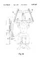
- FIG. 2is a front view of the FIG. 1 apparatus showing the laterally connected weight stack in a semi-perspective disposition
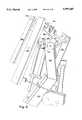
- FIG. 4is a right-front perspective view of the FIG. 1 apparatus showing a detail of the interconnection of cables to the four-bar linkage arms;
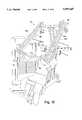
- FIG. 5is a front-right perspective view of the FIG. 1 apparatus showing a user seated in an exercise chest press ready position;
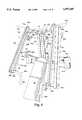
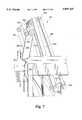
- FIG. 8is a left side view of the rear-upper portion of the FIG. 1 apparatus showing the tilted pivot axis mounting of one of the four-bar linkage arms to the central support bar member of the FIG. 1 apparatus;
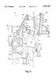
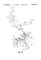
- FIG. 15is a side schematic view of an arrangement of interconnected levers which interconnect a foot pedal to the pivotable four-bar linkage arms for initially positioning the four-bar linkage arms;
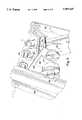
- FIG. 16is a top right-side perspective view of the upper-side of the central support bar of the FIG. 1 apparatus showing the pivot mounting brackets and pivot wheel stop mechanisms;
- FIG. 17is an upper right-side perspective view of the FIG. 1 apparatus without the seat and base components showing the four-bar linkage arms in an extended pivoted position and showing the interconnection and positioning of the cable and pulleys between the four-bar linkage arms and weight stack.
- support 18is preferably constructed of a rigid material such as steel, and includes a base member 19, a pair of post members 21a and 21b (FIG. 17), a cross bar assembly 62, and a pair of extensions 23a and 23b, all of which combine to form the structural elements of support 18.
- Base member 19preferably includes a first support member 19a, a second support member 19b and a mounting member 19c disposed therebetween.
- First and second support members 19a and 19bpreferably rest on a substantially horizontal, flat surface, such as the floor 17.
- a foot start 15is located adjacent first support member 19a so that a user can easily grasp handles 16a and 16b in order to begin exercising, as described in greater detail herein below.
- mounting member 19cis preferably supported at one end by first support member 19a, is supported at an opposite end by second support member 19b, and is preferably spaced from and substantially parallel to the floor 17.
- seat 20preferably includes a seat cushion 25 and a support cushion 27, is supported in a reclined position, and is preferably adjustable between a plurality of vertical positions.
- Seat cushion 25is supported by an angled seat mount 29 while support cushion 27 is supported by angled post members 21a and 21b.
- Seat 20is mounted at an angle, which is approximately 30° in the present embodiment, with respect to a plane perpendicular to floor 17, so as to properly orientate the user for performance of a chest press exercise motion.
- adjustment of seat 20is preferably enabled through a four-bar, gas-assist seat adjustment, although other methods of adjustment, for example hydraulic, may be utilized.
- a pin 33is insertable through each of a plurality of holes, in order to select the desired height of the seat.
- seat 20may be designed in a variety of configurations and dimensions, and may, or may not be adjustable.
- foot start 15is preferably located adjacent seat 20, and when activated by a user, allows the user to easily grasp handles 16a and 16b in order to begin exercising, as is known in the art.
- Foot start 15preferably includes an engagement rod 15a mounted to a first, forward end of assist lever 15b such that engagement of rod 15a by a user in the direction of arrow "G” moves the first end of assist lever also in the direction of arrow "G".
- Assist lever 15bis connected at a second end, opposite the first end, to one end of linkage 15c, by pin 15d, such that upon engagement of rod 15a by the user in the direction of arrow "G", linkage 15c moves in the direction indicated by arrow "H".
- Assist lever 15bis further connected to support 18 by pivot 15e.
- Linkage 15cis, in turn, connected an opposite end to center link 15f by pin 15g, such that movement of linkage 15c in the direction of arrow "H” pivots center link 15f in the direction indicated by arrow "I".
- Center link 15fis connected to support 18 by rod 15h, and is connected at a second end to bar 15g, such that pivoting center link 15f in the direction of arrow "I", moves bar 15g in a downward direction as indicated by arrow "J".
- the movement of rod 15g in the direction of arrow "J”moves rockers 15i and 15j and hence axes 15k and 151 which are connected thereto, in the direction of arrow "M".
- Axes 15k and 151are, in turn, rotationally connected to corresponding stop arms 35a and 35b mounted thereto, with rollers 37a and 37b of stop arms 35a and 35b abutting corresponding primary lever arms 36a and 36b (FIGS. 4 and 6). Movement of axes 15k and 151 therefore moves stop arms 35a and 35b, and rollers 37a and 37b, in the direction of arrow "N" to move the four bar linkages 14a and 14b toward the user until the user is able to grip the handles 16a and 16b.
- selectable weight mechanism 12is preferably a high-mass, short-travel (HMST) weight stack.
- HMSThigh-mass, short-travel
- the high-mass, short-travel weight mechanism 12provides the user with a higher mass weight stack and a shorter range of travel than conventional weight stacks.
- By increasing the mass and decreasing the range of travelthe speed of the selected weight is decreased during use, without slowing down the speed of the user, as described hereinbelow.
- Thisallows an individual to utilize strength training to train at higher contractal velocities s without the associated negative inertial effect found in conventional selectable weights, because as the speed of the weight is decreased, so is the negative inertial effect.
- Overcoming the negative inertial effectresults in smooth and predictable resistance through a complete range of motion.
- the distance "DC”is a function of the length of the user's arm.
- the distance a user's hand travels from the beginning to the end of one repetition of the exercisedefines a complete range of motion.
- the massis doubled, the total load the user feels during the performance of an exercise routine is the same as with a conventional chest press machine.
- This effectis achieved by changing the mechanical advantage to increase the leverage the user has over the selected weight plates from 1.8:1 (force exerted by user:weight) in a conventional system, to a 0.9:1 ratio in the present embodiment.
- the ratiomay be changed by attaching cable 58 (FIG. 17) at an appropriate attachment point along primary lever arm 36a and 36b, in the present embodiment, as determined by conventional engineering techniques.
- the criteria for determining the placement of cable 58is that while performing an exercise on the chest press exercise apparatus of the present invention, the user should feel a resistance comparable to that felt while performing an exercise on a conventional chest press exercise apparatus while being able to exercise at higher contractal velocities.
- the increase in massis, in turn, determined by several considerations, such as cost, structural load placed on the apparatus by the mass, as well as the ability to readily achieve the desired leverage for a given mass.
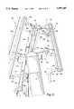
- the primary and follower lever armslie and travel in a common plane which is tilted at an angle relative to a vertical plane, where the vertical plane is perpendicular to horizontal plane "A" underlying the base 19 of the apparatus.
- the tilted common planeis illustrated as plane “T” (FIG. 1), which is tilted with respect to the vertical plane "Z”, where plane “Z” intersects the y- axis, and is perpendicular to plane "A", and where the y- axis bisects the seat 27.
- the distance between primary axle 46a and secondary axle 50ais 3.75 inches.
- secondary axle 50ais mounted to block 52a (FIG. 2) which is part of support arm 42a.
- Block 52ais preferably welded to a support arm 42a, but may be attached in any suitable manner as long as block 52a remains stationary while supporting follower lever arm 38a.
- secondary axle 50amay be directly mounted to support arm 42a.
- the handle lever arm 40ais the forward most component of the four bar linkage 14a.
- the handle lever arm 40ais approximately 4.5 inches in length between the pivot points 44a and 48a includes a handle 16a extending therefrom.
- the follower lever arm 38ais preferably not disposed parallel with respect to primary lever arm 36a.
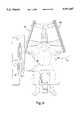
- the handle 16ais preferably rigidly connected to the handle lever arm 40a, and preferably includes a first handle portion 16x extending in a first, perpendicular direction therefrom, and a second handle portion 16y curving outwardly from the first portion 16x, preferably at a 90° angle, and preferably slightly downwardly.
- the tilted axesmaintain the correct biomechanical alignment of the wrists.
- a neutral gripi.e., when the user grasps handle portions 16y so that their hands are substantially parallel to handle lever arm 40a, as shown in FIGS. 9 and 10
- the four-bar linkage mechanismsalso enable the user to maintain the correct biomechanical alignment of the joints.
- the handledoes not substantially twist or change orientation relative to the horizontal (A) and vertical (Z and B) planes throughout the user's complete range of motion, i.e., displacement of the four-bar linkage mechanisms.
- pulley system 56preferably includes a cable 58 attached at a first end to primary lever arm 36a and attached at a second end to primary lever arm 36b.
- the cable 58is preferably attached by pivot blocks 17a and 17b to both of the primary lever arms 36a and 36b, respectively.
- the cable 58is attached at approximately 55% of the distance between the first pivot points 46a and 46b to the second pivot points 44a and 44b, respectively, as measured starting from the second pivot points 46a and 46b, in order to increase the mechanical advantage the user has over the weight to be lifted.
- Floating pulley 60is attached at one end to cable 30 by pivot block 63. Movement of floating pulley 60 in the direction of arrow M, therefore, also operates to move cable 30 in the direction of arrow M.
- cable 30is routed through a pulley 68a, and then through pulley 68b, attached to the exterior of weight mechanism 12. Cable 30 is then received within housing 22 of weight mechanism 12, where the cable is preferably routed through pulleys 70a and 70b (FIG. 17). Pulleys 70a and 70b operate to orientate the cable above the plurality of selectable weights 24, disposed within housing 22. Cable 30 exits the housing at an aperture 72 where it is operatively connected to central rod 32, as described above. Again, any number of pulleys may be utilized to route cable 30, as long as the cable is operatively connected to central rod 32.
- chest press machine 10Prior to performance of an exercise routine, a user will first adjust seat 20 to a desired position in which the user's feet will preferably be in contact with floor 17. The user then selects the desired weight for performance of the exercise by inserting pin 34 into the transverse hole of the appropriate weight plate, as described above. Due to the off-center orientation of weight mechanism 12 with respect to seat 20, the user may select the weight from either a seated or a standing position. In either case, after the weight has been selected the user should be seated in seat 20 with the user's back preferably resting against support cushion 27. The direction the user is facing is considered the forward facing direction for purposes of this invention.
Landscapes
- Health & Medical Sciences (AREA)
- Orthopedic Medicine & Surgery (AREA)
- General Health & Medical Sciences (AREA)
- Physical Education & Sports Medicine (AREA)
- Life Sciences & Earth Sciences (AREA)
- Biophysics (AREA)
- Rehabilitation Tools (AREA)
Abstract
Description
Claims (27)
Priority Applications (2)
| Application Number | Priority Date | Filing Date | Title |
|---|---|---|---|
| US08/941,455US5997447A (en) | 1996-09-30 | 1997-09-30 | Chest press apparatus for exercising regions of the upper body |
| US09/395,632US6142917A (en) | 1996-09-30 | 1999-09-14 | Chest press apparatus for exercising regions of the upper body |
Applications Claiming Priority (2)
| Application Number | Priority Date | Filing Date | Title |
|---|---|---|---|
| US2552996P | 1996-09-30 | 1996-09-30 | |
| US08/941,455US5997447A (en) | 1996-09-30 | 1997-09-30 | Chest press apparatus for exercising regions of the upper body |
Related Child Applications (1)
| Application Number | Title | Priority Date | Filing Date |
|---|---|---|---|
| US09/395,632ContinuationUS6142917A (en) | 1996-09-30 | 1999-09-14 | Chest press apparatus for exercising regions of the upper body |
Publications (1)
| Publication Number | Publication Date |
|---|---|
| US5997447Atrue US5997447A (en) | 1999-12-07 |
Family
ID=26699875
Family Applications (2)
| Application Number | Title | Priority Date | Filing Date |
|---|---|---|---|
| US08/941,455Expired - Fee RelatedUS5997447A (en) | 1996-09-30 | 1997-09-30 | Chest press apparatus for exercising regions of the upper body |
| US09/395,632Expired - Fee RelatedUS6142917A (en) | 1996-09-30 | 1999-09-14 | Chest press apparatus for exercising regions of the upper body |
Family Applications After (1)
| Application Number | Title | Priority Date | Filing Date |
|---|---|---|---|
| US09/395,632Expired - Fee RelatedUS6142917A (en) | 1996-09-30 | 1999-09-14 | Chest press apparatus for exercising regions of the upper body |
Country Status (1)
| Country | Link |
|---|---|
| US (2) | US5997447A (en) |
Cited By (57)
| Publication number | Priority date | Publication date | Assignee | Title |
|---|---|---|---|---|
| USD439943S1 (en) | 2000-02-15 | 2001-04-03 | Hoist Fitness Systems | Exercise arm unit for an exercise machine |
| USD440610S1 (en) | 2000-02-15 | 2001-04-17 | Hoist Fitness Systems | Exercise machine |
| US6264588B1 (en) | 2000-01-20 | 2001-07-24 | Joseph K. Ellis | Composite motion machine |
| US6579213B1 (en) | 2000-02-29 | 2003-06-17 | Hoist Fitness Systems | Exercise arm assembly for exercise machine |
| US20030166439A1 (en)* | 2002-03-04 | 2003-09-04 | Raymond Giannelli | Rowing machine |
| USD480773S1 (en) | 2002-11-13 | 2003-10-14 | Cybex International, Inc. | Weight stack support frame |
| US20040162195A1 (en)* | 2003-02-14 | 2004-08-19 | Habing Douglas J. | Single apparatus converging/diverging exercise machine |
| US20040162194A1 (en)* | 2003-02-14 | 2004-08-19 | Habing Douglas J. | Exercise machine with adjustable range of motion |
| WO2004101078A1 (en)* | 2003-05-15 | 2004-11-25 | Yun-Seok Choi | Apparatus for three-dimensional anaerobic exercise |
| US20060035764A1 (en)* | 2004-08-13 | 2006-02-16 | Webber Randall T | Exercise arm assembly for exercise machine |
| US20060128536A1 (en)* | 2006-01-11 | 2006-06-15 | Herrington William B | Exercise apparatus |
| US7070546B1 (en) | 2002-07-05 | 2006-07-04 | Joseph Grasso | Exercise apparatus including multiple function aspects and small footprint |
| US7549949B2 (en) | 2003-08-04 | 2009-06-23 | Hoist Fitness Systems, Inc. | Chest press exercise machine with self-aligning pivoting user support |
| US20090170669A1 (en)* | 2007-12-21 | 2009-07-02 | Cybex International, Inc. | Adjustable assembly for exercise apparatus |
| US7563209B2 (en) | 2006-09-05 | 2009-07-21 | Hoist Fitness Systems, Inc. | Leg exercise machine with self-aligning pivoting seat |
| US7563214B2 (en) | 2000-02-29 | 2009-07-21 | Hoist Fitness Systems, Inc. | Exercise arm assembly for exercise machine |
| US20100009818A1 (en)* | 2008-07-09 | 2010-01-14 | Tom Simonson | Multi Axes Exercise Apparatus |
| US7654940B2 (en) | 2006-09-06 | 2010-02-02 | Hoist Fitness Systems, Inc. | Arm exercise machine with self-aligning pivoting user support |
| US7670269B2 (en) | 2006-09-05 | 2010-03-02 | Hoist Fitness Systems, Inc. | Chest press exercise machine with self-aligning pivoting user support |
| US7794371B2 (en) | 2003-08-04 | 2010-09-14 | Hoist Fitness Systems, Inc. | Lat exercise machine with self-aligning pivoting user support |
| US20110092343A1 (en)* | 2003-02-14 | 2011-04-21 | Habing Douglas J | Single Apparatus Converging/Diverging Exercise Machine |
| US7938760B1 (en) | 2008-10-17 | 2011-05-10 | Hoist Fitness Systems, Inc. | Exercise machine with lifting arm |
| US7981010B1 (en)* | 2003-08-04 | 2011-07-19 | Hoist Fitness Systems, Inc. | Exercise machine with multi-function user engagement device |
| US7993251B1 (en) | 2003-08-04 | 2011-08-09 | Hoist Fitness Systems, Inc. | Pectoral fly exercise machine |
| US8177693B2 (en) | 2010-02-25 | 2012-05-15 | Hoist Fitness Systems, Inc. | Calf exercise machine with rocking user support |
| US8562496B2 (en) | 2010-03-05 | 2013-10-22 | Hoist Fitness Systems, Inc. | Thigh exercise machine with rocking user support |
| US8734304B2 (en) | 2010-03-04 | 2014-05-27 | Hoist Fitness Systems, Inc. | Low back exercise machine with rocking user support |
| US8864635B1 (en)* | 2010-10-07 | 2014-10-21 | Brunswick Corporation | Resistance training exercise apparatus |
| US20140336018A1 (en)* | 2013-05-10 | 2014-11-13 | Precor Incorporated | Fitness equipment unit |
| US9539460B2 (en) | 2007-07-26 | 2017-01-10 | Joseph K. Ellis | Weight training machines |
| US9636540B2 (en) | 2015-03-10 | 2017-05-02 | True Fitness Technology, Inc. | Adjustable stride elliptical motion exercise machine with large stride variability and fast adjustment |
| US10188890B2 (en) | 2013-12-26 | 2019-01-29 | Icon Health & Fitness, Inc. | Magnetic resistance mechanism in a cable machine |
| US10252109B2 (en) | 2016-05-13 | 2019-04-09 | Icon Health & Fitness, Inc. | Weight platform treadmill |
| US10258828B2 (en) | 2015-01-16 | 2019-04-16 | Icon Health & Fitness, Inc. | Controls for an exercise device |
| US10272317B2 (en) | 2016-03-18 | 2019-04-30 | Icon Health & Fitness, Inc. | Lighted pace feature in a treadmill |
| US10279212B2 (en) | 2013-03-14 | 2019-05-07 | Icon Health & Fitness, Inc. | Strength training apparatus with flywheel and related methods |
| US10293211B2 (en) | 2016-03-18 | 2019-05-21 | Icon Health & Fitness, Inc. | Coordinated weight selection |
| US10343017B2 (en) | 2016-11-01 | 2019-07-09 | Icon Health & Fitness, Inc. | Distance sensor for console positioning |
| US10376736B2 (en) | 2016-10-12 | 2019-08-13 | Icon Health & Fitness, Inc. | Cooling an exercise device during a dive motor runway condition |
| US10426989B2 (en) | 2014-06-09 | 2019-10-01 | Icon Health & Fitness, Inc. | Cable system incorporated into a treadmill |
| US10433612B2 (en) | 2014-03-10 | 2019-10-08 | Icon Health & Fitness, Inc. | Pressure sensor to quantify work |
| US10441844B2 (en) | 2016-07-01 | 2019-10-15 | Icon Health & Fitness, Inc. | Cooling systems and methods for exercise equipment |
| US10441840B2 (en) | 2016-03-18 | 2019-10-15 | Icon Health & Fitness, Inc. | Collapsible strength exercise machine |
| US10449416B2 (en) | 2015-08-26 | 2019-10-22 | Icon Health & Fitness, Inc. | Strength exercise mechanisms |
| US10471299B2 (en) | 2016-07-01 | 2019-11-12 | Icon Health & Fitness, Inc. | Systems and methods for cooling internal exercise equipment components |
| US10493349B2 (en) | 2016-03-18 | 2019-12-03 | Icon Health & Fitness, Inc. | Display on exercise device |
| US10500473B2 (en) | 2016-10-10 | 2019-12-10 | Icon Health & Fitness, Inc. | Console positioning |
| US10543395B2 (en) | 2016-12-05 | 2020-01-28 | Icon Health & Fitness, Inc. | Offsetting treadmill deck weight during operation |
| US10561894B2 (en) | 2016-03-18 | 2020-02-18 | Icon Health & Fitness, Inc. | Treadmill with removable supports |
| US10625137B2 (en) | 2016-03-18 | 2020-04-21 | Icon Health & Fitness, Inc. | Coordinated displays in an exercise device |
| US10661114B2 (en) | 2016-11-01 | 2020-05-26 | Icon Health & Fitness, Inc. | Body weight lift mechanism on treadmill |
| US10729965B2 (en) | 2017-12-22 | 2020-08-04 | Icon Health & Fitness, Inc. | Audible belt guide in a treadmill |
| US10940360B2 (en) | 2015-08-26 | 2021-03-09 | Icon Health & Fitness, Inc. | Strength exercise mechanisms |
| US10953305B2 (en) | 2015-08-26 | 2021-03-23 | Icon Health & Fitness, Inc. | Strength exercise mechanisms |
| US11451108B2 (en) | 2017-08-16 | 2022-09-20 | Ifit Inc. | Systems and methods for axial impact resistance in electric motors |
| CN118056581A (en)* | 2022-11-18 | 2024-05-21 | 新科技健康有限公司 | Rotary handle |
| EP4371624A1 (en)* | 2022-11-18 | 2024-05-22 | Newtech Wellness Co., Ltd. | Auto-rotating handle |
Families Citing this family (16)
| Publication number | Priority date | Publication date | Assignee | Title |
|---|---|---|---|---|
| US20030092543A1 (en)* | 2001-11-13 | 2003-05-15 | Cybex International, Inc. | Upper torso exercise machine |
| US7666123B2 (en)* | 2001-11-13 | 2010-02-23 | Cybex International, Inc. | Upper torso exercise machine |
| US6682466B1 (en) | 2002-12-10 | 2004-01-27 | Northland Industries, Inc. | Motion translation arrangement for limiting the rate of lever arm convergence in an exercise machine |
| USD497190S1 (en) | 2003-02-21 | 2004-10-12 | Cybex International, Inc. | Lateral raise exercise machine |
| USD513287S1 (en)* | 2004-01-23 | 2005-12-27 | Rodolfo Panatta | Body-building machine |
| USD523496S1 (en)* | 2005-03-22 | 2006-06-20 | Sherman Grider | Weight shroud |
| USD613350S1 (en)* | 2009-03-03 | 2010-04-06 | Johnson Health Tech Co., Ltd. | Exercise apparatus |
| USD612437S1 (en)* | 2009-03-03 | 2010-03-23 | Johnson Health Tech Co., Ltd. | Exercise apparatus |
| CN106457025A (en)* | 2014-03-11 | 2017-02-22 | 赛百斯国际健身器材有限公司 | Arm extension exercise apparatus |
| US10166435B2 (en) | 2014-03-11 | 2019-01-01 | Cybex International, Inc. | Back extension exercise apparatus |
| US9555274B1 (en)* | 2015-02-11 | 2017-01-31 | Brunswick Corporation | Seat adjustment devices and exercise apparatuses having seat adjustment devices |
| RU2620488C1 (en)* | 2016-01-27 | 2017-05-25 | Дмитрий Давидович Слободник | Press machine |
| EP3681457A4 (en)* | 2017-09-15 | 2021-06-09 | David Health Solutions Ltd. | REHABILITATION DEVICE AND ITS USE TO WORK THE SHOULDER REGION |
| US12053674B1 (en)* | 2018-04-12 | 2024-08-06 | AI Incorporated | Smart gym equipment |
| US11642566B2 (en)* | 2020-07-22 | 2023-05-09 | Joseph K. Ellis | Adjustable four-bar linkage assembly exercise station |
| US20220370847A1 (en)* | 2021-05-21 | 2022-11-24 | Theo GRIVAKIS | Adjustable exercise apparatus |
Citations (6)
| Publication number | Priority date | Publication date | Assignee | Title |
|---|---|---|---|---|
| US4411424A (en)* | 1982-02-08 | 1983-10-25 | Barnett Robert V | Weight lifting exercise apparatus |
| US5336148A (en)* | 1992-02-19 | 1994-08-09 | Vectra Fitness, Inc. | Machine for performing press exercises |
| US5437589A (en)* | 1993-12-20 | 1995-08-01 | Habing; Theodore J. | Upper body exercise machine |
| US5554089A (en)* | 1994-09-16 | 1996-09-10 | Hammer Strength Corporation | Military press exercise machine |
| US5582564A (en)* | 1994-02-07 | 1996-12-10 | Southern Xercise, Inc. | Upper torso exercise method |
| US5707323A (en)* | 1995-03-10 | 1998-01-13 | Simonson; Roy | Method and apparatus for exercising the rear deltoid muscle |
- 1997
- 1997-09-30USUS08/941,455patent/US5997447A/ennot_activeExpired - Fee Related
- 1999
- 1999-09-14USUS09/395,632patent/US6142917A/ennot_activeExpired - Fee Related
Patent Citations (6)
| Publication number | Priority date | Publication date | Assignee | Title |
|---|---|---|---|---|
| US4411424A (en)* | 1982-02-08 | 1983-10-25 | Barnett Robert V | Weight lifting exercise apparatus |
| US5336148A (en)* | 1992-02-19 | 1994-08-09 | Vectra Fitness, Inc. | Machine for performing press exercises |
| US5437589A (en)* | 1993-12-20 | 1995-08-01 | Habing; Theodore J. | Upper body exercise machine |
| US5582564A (en)* | 1994-02-07 | 1996-12-10 | Southern Xercise, Inc. | Upper torso exercise method |
| US5554089A (en)* | 1994-09-16 | 1996-09-10 | Hammer Strength Corporation | Military press exercise machine |
| US5707323A (en)* | 1995-03-10 | 1998-01-13 | Simonson; Roy | Method and apparatus for exercising the rear deltoid muscle |
Cited By (80)
| Publication number | Priority date | Publication date | Assignee | Title |
|---|---|---|---|---|
| US6264588B1 (en) | 2000-01-20 | 2001-07-24 | Joseph K. Ellis | Composite motion machine |
| USD440610S1 (en) | 2000-02-15 | 2001-04-17 | Hoist Fitness Systems | Exercise machine |
| USD439943S1 (en) | 2000-02-15 | 2001-04-03 | Hoist Fitness Systems | Exercise arm unit for an exercise machine |
| US20060116254A1 (en)* | 2000-02-29 | 2006-06-01 | Webber Randall T | Exercise arm assembly for exercise machine |
| US6579213B1 (en) | 2000-02-29 | 2003-06-17 | Hoist Fitness Systems | Exercise arm assembly for exercise machine |
| US7563214B2 (en) | 2000-02-29 | 2009-07-21 | Hoist Fitness Systems, Inc. | Exercise arm assembly for exercise machine |
| US7384381B2 (en) | 2000-02-29 | 2008-06-10 | Hoist Fitness Systems, Inc. | Exercise arm assembly for exercise machine |
| US20030166439A1 (en)* | 2002-03-04 | 2003-09-04 | Raymond Giannelli | Rowing machine |
| US8944969B2 (en)* | 2002-03-04 | 2015-02-03 | Cybex International, Inc. | Rowing machine |
| US7070546B1 (en) | 2002-07-05 | 2006-07-04 | Joseph Grasso | Exercise apparatus including multiple function aspects and small footprint |
| USD480773S1 (en) | 2002-11-13 | 2003-10-14 | Cybex International, Inc. | Weight stack support frame |
| US20040162194A1 (en)* | 2003-02-14 | 2004-08-19 | Habing Douglas J. | Exercise machine with adjustable range of motion |
| US7811211B2 (en) | 2003-02-14 | 2010-10-12 | Habing Douglas J | Single apparatus converging/diverging exercise machine |
| US20110092343A1 (en)* | 2003-02-14 | 2011-04-21 | Habing Douglas J | Single Apparatus Converging/Diverging Exercise Machine |
| US20040162195A1 (en)* | 2003-02-14 | 2004-08-19 | Habing Douglas J. | Single apparatus converging/diverging exercise machine |
| US20070042877A1 (en)* | 2003-05-15 | 2007-02-22 | Choi Yun-Seok | Apparatus for three-dimensional anaerobic exercise |
| WO2004101078A1 (en)* | 2003-05-15 | 2004-11-25 | Yun-Seok Choi | Apparatus for three-dimensional anaerobic exercise |
| US7549949B2 (en) | 2003-08-04 | 2009-06-23 | Hoist Fitness Systems, Inc. | Chest press exercise machine with self-aligning pivoting user support |
| US7993251B1 (en) | 2003-08-04 | 2011-08-09 | Hoist Fitness Systems, Inc. | Pectoral fly exercise machine |
| US7981010B1 (en)* | 2003-08-04 | 2011-07-19 | Hoist Fitness Systems, Inc. | Exercise machine with multi-function user engagement device |
| US7794371B2 (en) | 2003-08-04 | 2010-09-14 | Hoist Fitness Systems, Inc. | Lat exercise machine with self-aligning pivoting user support |
| US20060035764A1 (en)* | 2004-08-13 | 2006-02-16 | Webber Randall T | Exercise arm assembly for exercise machine |
| US7322906B2 (en) | 2004-08-13 | 2008-01-29 | Webber Randall T | Exercise arm assembly for exercise machine |
| US20060128536A1 (en)* | 2006-01-11 | 2006-06-15 | Herrington William B | Exercise apparatus |
| US7670269B2 (en) | 2006-09-05 | 2010-03-02 | Hoist Fitness Systems, Inc. | Chest press exercise machine with self-aligning pivoting user support |
| US7563209B2 (en) | 2006-09-05 | 2009-07-21 | Hoist Fitness Systems, Inc. | Leg exercise machine with self-aligning pivoting seat |
| US7654940B2 (en) | 2006-09-06 | 2010-02-02 | Hoist Fitness Systems, Inc. | Arm exercise machine with self-aligning pivoting user support |
| US9539460B2 (en) | 2007-07-26 | 2017-01-10 | Joseph K. Ellis | Weight training machines |
| US8992392B2 (en) | 2007-12-21 | 2015-03-31 | Cybex International, Inc. | Exercise apparatus |
| US9089737B2 (en) | 2007-12-21 | 2015-07-28 | Cybex International, Inc. | Exercise apparatus and method with selectively variable stabilization |
| US9211434B2 (en) | 2007-12-21 | 2015-12-15 | Cybex International, Inc. | Adjustable assembly for exercise apparatus |
| US20110183816A1 (en)* | 2007-12-21 | 2011-07-28 | Cybex International, Inc. | Exercise apparatus and method with selectively variable stabilization |
| US20110183817A1 (en)* | 2007-12-21 | 2011-07-28 | Cybex International, Inc. | Exercise apparatus and method with selectively variable stabilization |
| US20090170675A1 (en)* | 2007-12-21 | 2009-07-02 | Cybex International, Inc. | Exercise apparatus and method with selectively variable stabilization |
| US8057367B2 (en) | 2007-12-21 | 2011-11-15 | Cybex International, Inc. | Exercise apparatus and method with selectively variable stabilization |
| US8070658B2 (en) | 2007-12-21 | 2011-12-06 | Cybex International, Inc. | Exercise apparatus and method with selectively variable stabilization |
| US20090170669A1 (en)* | 2007-12-21 | 2009-07-02 | Cybex International, Inc. | Adjustable assembly for exercise apparatus |
| US20090170668A1 (en)* | 2007-12-21 | 2009-07-02 | Cybex International, Inc. | Exercise Apparatus |
| US8708872B2 (en) | 2007-12-21 | 2014-04-29 | Cybex International, Inc. | Adjustable assembly for exercise apparatus |
| US7938761B2 (en)* | 2008-07-09 | 2011-05-10 | Tom Simonson | Multi axes exercise apparatus |
| US20100009818A1 (en)* | 2008-07-09 | 2010-01-14 | Tom Simonson | Multi Axes Exercise Apparatus |
| US11759668B2 (en) | 2008-10-17 | 2023-09-19 | Hoist Fitness Systems, Inc. | Exercise machine with lifting arm |
| US10639513B2 (en) | 2008-10-17 | 2020-05-05 | Hoist Fitness Systems, Inc. | Exercise machine with lifting arm |
| US7938760B1 (en) | 2008-10-17 | 2011-05-10 | Hoist Fitness Systems, Inc. | Exercise machine with lifting arm |
| US11000722B2 (en) | 2008-10-17 | 2021-05-11 | Hoist Fitness Systems, Inc. | Exercise machine with lifting arm |
| US10646739B2 (en) | 2008-10-17 | 2020-05-12 | Hoist Fitness Systems, Inc. | Exercise machine with lifting arm |
| US9861850B1 (en) | 2008-10-17 | 2018-01-09 | Hoist Fitness Systems, Inc. | Exercise machine with lifting arm |
| US8177693B2 (en) | 2010-02-25 | 2012-05-15 | Hoist Fitness Systems, Inc. | Calf exercise machine with rocking user support |
| US8734304B2 (en) | 2010-03-04 | 2014-05-27 | Hoist Fitness Systems, Inc. | Low back exercise machine with rocking user support |
| US8562496B2 (en) | 2010-03-05 | 2013-10-22 | Hoist Fitness Systems, Inc. | Thigh exercise machine with rocking user support |
| US8864635B1 (en)* | 2010-10-07 | 2014-10-21 | Brunswick Corporation | Resistance training exercise apparatus |
| US10279212B2 (en) | 2013-03-14 | 2019-05-07 | Icon Health & Fitness, Inc. | Strength training apparatus with flywheel and related methods |
| US20140336018A1 (en)* | 2013-05-10 | 2014-11-13 | Precor Incorporated | Fitness equipment unit |
| US9320937B2 (en)* | 2013-05-10 | 2016-04-26 | Precor Incorporated | Fitness equipment unit |
| US10188890B2 (en) | 2013-12-26 | 2019-01-29 | Icon Health & Fitness, Inc. | Magnetic resistance mechanism in a cable machine |
| US10433612B2 (en) | 2014-03-10 | 2019-10-08 | Icon Health & Fitness, Inc. | Pressure sensor to quantify work |
| US10426989B2 (en) | 2014-06-09 | 2019-10-01 | Icon Health & Fitness, Inc. | Cable system incorporated into a treadmill |
| US10258828B2 (en) | 2015-01-16 | 2019-04-16 | Icon Health & Fitness, Inc. | Controls for an exercise device |
| US9636540B2 (en) | 2015-03-10 | 2017-05-02 | True Fitness Technology, Inc. | Adjustable stride elliptical motion exercise machine with large stride variability and fast adjustment |
| US10953305B2 (en) | 2015-08-26 | 2021-03-23 | Icon Health & Fitness, Inc. | Strength exercise mechanisms |
| US10449416B2 (en) | 2015-08-26 | 2019-10-22 | Icon Health & Fitness, Inc. | Strength exercise mechanisms |
| US10940360B2 (en) | 2015-08-26 | 2021-03-09 | Icon Health & Fitness, Inc. | Strength exercise mechanisms |
| US10441840B2 (en) | 2016-03-18 | 2019-10-15 | Icon Health & Fitness, Inc. | Collapsible strength exercise machine |
| US10493349B2 (en) | 2016-03-18 | 2019-12-03 | Icon Health & Fitness, Inc. | Display on exercise device |
| US10561894B2 (en) | 2016-03-18 | 2020-02-18 | Icon Health & Fitness, Inc. | Treadmill with removable supports |
| US10625137B2 (en) | 2016-03-18 | 2020-04-21 | Icon Health & Fitness, Inc. | Coordinated displays in an exercise device |
| US10293211B2 (en) | 2016-03-18 | 2019-05-21 | Icon Health & Fitness, Inc. | Coordinated weight selection |
| US10272317B2 (en) | 2016-03-18 | 2019-04-30 | Icon Health & Fitness, Inc. | Lighted pace feature in a treadmill |
| US10252109B2 (en) | 2016-05-13 | 2019-04-09 | Icon Health & Fitness, Inc. | Weight platform treadmill |
| US10441844B2 (en) | 2016-07-01 | 2019-10-15 | Icon Health & Fitness, Inc. | Cooling systems and methods for exercise equipment |
| US10471299B2 (en) | 2016-07-01 | 2019-11-12 | Icon Health & Fitness, Inc. | Systems and methods for cooling internal exercise equipment components |
| US10500473B2 (en) | 2016-10-10 | 2019-12-10 | Icon Health & Fitness, Inc. | Console positioning |
| US10376736B2 (en) | 2016-10-12 | 2019-08-13 | Icon Health & Fitness, Inc. | Cooling an exercise device during a dive motor runway condition |
| US10661114B2 (en) | 2016-11-01 | 2020-05-26 | Icon Health & Fitness, Inc. | Body weight lift mechanism on treadmill |
| US10343017B2 (en) | 2016-11-01 | 2019-07-09 | Icon Health & Fitness, Inc. | Distance sensor for console positioning |
| US10543395B2 (en) | 2016-12-05 | 2020-01-28 | Icon Health & Fitness, Inc. | Offsetting treadmill deck weight during operation |
| US11451108B2 (en) | 2017-08-16 | 2022-09-20 | Ifit Inc. | Systems and methods for axial impact resistance in electric motors |
| US10729965B2 (en) | 2017-12-22 | 2020-08-04 | Icon Health & Fitness, Inc. | Audible belt guide in a treadmill |
| CN118056581A (en)* | 2022-11-18 | 2024-05-21 | 新科技健康有限公司 | Rotary handle |
| EP4371624A1 (en)* | 2022-11-18 | 2024-05-22 | Newtech Wellness Co., Ltd. | Auto-rotating handle |
Also Published As
| Publication number | Publication date |
|---|---|
| US6142917A (en) | 2000-11-07 |
Similar Documents
| Publication | Publication Date | Title |
|---|---|---|
| US5997447A (en) | Chest press apparatus for exercising regions of the upper body | |
| US5989165A (en) | Incline press apparatus for exercising regions of the upper body | |
| US6254516B1 (en) | Shoulder press apparatus for exercising regions of the upper body | |
| US6071216A (en) | Pull down apparatus for exercising regions of the upper body | |
| US6056678A (en) | Arm curl apparatus for exercising regions of the upper body | |
| US5971896A (en) | Shoulder press apparatus for exercising regions of the upper body | |
| US6080091A (en) | Exercise machine press arm | |
| US7794371B2 (en) | Lat exercise machine with self-aligning pivoting user support | |
| EP2188022B1 (en) | Seated exercise apparatus | |
| US7052446B2 (en) | Lat pulldown weight training machine | |
| US6746385B1 (en) | Upper body exercise machine | |
| US5437589A (en) | Upper body exercise machine | |
| US5573485A (en) | Exercising and stretching apparatus | |
| US7070545B2 (en) | Leg press and abdominal crunch exercise machine | |
| US6394936B1 (en) | Convergent exercise machine and method | |
| US5810701A (en) | Motion translation arrangement for exercise machine | |
| US5370594A (en) | Adjustable and configurable exercise machine | |
| US6988977B2 (en) | Exercise arm assembly for exercise machine | |
| JP3117451B2 (en) | Exercise machine | |
| US6468188B1 (en) | Exercise apparatus for gluteus and hamstring muscles | |
| US20110028277A1 (en) | Seated exercise apparatus | |
| US7641595B2 (en) | Golf exercise device | |
| US20070093363A1 (en) | Golf swing simulator and exercise device | |
| US6533709B1 (en) | Standing push/pull exercise machine and method of using the same | |
| US20040266591A1 (en) | Exercise machine |
Legal Events
| Date | Code | Title | Description |
|---|---|---|---|
| AS | Assignment | Owner name:CYBEX INTERNATIONAL, INC., MASSACHUSETTS Free format text:ASSIGNMENT OF ASSIGNORS INTEREST;ASSIGNORS:GIANNELLI, RAYMOND;LEIPHEIMER, JERRY K.;REEL/FRAME:009189/0153;SIGNING DATES FROM 19980422 TO 19980504 | |
| FEPP | Fee payment procedure | Free format text:PAYOR NUMBER ASSIGNED (ORIGINAL EVENT CODE: ASPN); ENTITY STATUS OF PATENT OWNER: LARGE ENTITY | |
| FEPP | Fee payment procedure | Free format text:PAYOR NUMBER ASSIGNED (ORIGINAL EVENT CODE: ASPN); ENTITY STATUS OF PATENT OWNER: LARGE ENTITY Free format text:PAYER NUMBER DE-ASSIGNED (ORIGINAL EVENT CODE: RMPN); ENTITY STATUS OF PATENT OWNER: LARGE ENTITY | |
| FEPP | Fee payment procedure | Free format text:PAYER NUMBER DE-ASSIGNED (ORIGINAL EVENT CODE: RMPN); ENTITY STATUS OF PATENT OWNER: LARGE ENTITY Free format text:PAYOR NUMBER ASSIGNED (ORIGINAL EVENT CODE: ASPN); ENTITY STATUS OF PATENT OWNER: LARGE ENTITY | |
| FEPP | Fee payment procedure | Free format text:PAYER NUMBER DE-ASSIGNED (ORIGINAL EVENT CODE: RMPN); ENTITY STATUS OF PATENT OWNER: LARGE ENTITY Free format text:PAYOR NUMBER ASSIGNED (ORIGINAL EVENT CODE: ASPN); ENTITY STATUS OF PATENT OWNER: LARGE ENTITY | |
| FPAY | Fee payment | Year of fee payment:4 | |
| AS | Assignment | Owner name:HILCO CAPITAL LLP, ILLINOIS Free format text:SECURITY INTEREST;ASSIGNOR:CYBEX INTERNATIONAL, INC.;REEL/FRAME:013879/0826 Effective date:20030716 | |
| AS | Assignment | Owner name:CIT GROUP/BUSINESS CREDIT, INC., THE, NORTH CAROLI Free format text:NOTICE OF GRANT OF SECURITY INTEREST;ASSIGNOR:CYBEX INTERNATIONAL, INC.;REEL/FRAME:013913/0712 Effective date:20030716 | |
| AS | Assignment | Owner name:CYBEX INTERNATIONAL, INC., MASSACHUSETTS Free format text:RELEASE OF SECURITY INTEREST;ASSIGNOR:HILCO CAPITAL, LP;REEL/FRAME:016309/0328 Effective date:20040713 | |
| FPAY | Fee payment | Year of fee payment:8 | |
| AS | Assignment | Owner name:CYBEX INTERNATIONAL, INC., MASSACHUSETTS Free format text:RELEASE BY SECURED PARTY;ASSIGNOR:CIT GROUP/BUSINESS CREDIT, INC.;REEL/FRAME:026046/0651 Effective date:20110328 | |
| REMI | Maintenance fee reminder mailed | ||
| LAPS | Lapse for failure to pay maintenance fees | ||
| STCH | Information on status: patent discontinuation | Free format text:PATENT EXPIRED DUE TO NONPAYMENT OF MAINTENANCE FEES UNDER 37 CFR 1.362 | |
| FP | Lapsed due to failure to pay maintenance fee | Effective date:20111207 |