US5996758A - Electromagnetically controlled bi-directional one-way clutch apparatus - Google Patents
Electromagnetically controlled bi-directional one-way clutch apparatusDownload PDFInfo
- Publication number
- US5996758A US5996758AUS09/005,179US517998AUS5996758AUS 5996758 AUS5996758 AUS 5996758AUS 517998 AUS517998 AUS 517998AUS 5996758 AUS5996758 AUS 5996758A
- Authority
- US
- United States
- Prior art keywords
- motor vehicle
- clutch
- directional
- strut
- electromagnetically controlled
- Prior art date
- Legal status (The legal status is an assumption and is not a legal conclusion. Google has not performed a legal analysis and makes no representation as to the accuracy of the status listed.)
- Expired - Lifetime
Links
Images


Classifications
- F—MECHANICAL ENGINEERING; LIGHTING; HEATING; WEAPONS; BLASTING
- F16—ENGINEERING ELEMENTS AND UNITS; GENERAL MEASURES FOR PRODUCING AND MAINTAINING EFFECTIVE FUNCTIONING OF MACHINES OR INSTALLATIONS; THERMAL INSULATION IN GENERAL
- F16D—COUPLINGS FOR TRANSMITTING ROTATION; CLUTCHES; BRAKES
- F16D27/00—Magnetically- or electrically- actuated clutches; Control or electric circuits therefor
- F16D27/004—Magnetically- or electrically- actuated clutches; Control or electric circuits therefor with permanent magnets combined with electromagnets
- F—MECHANICAL ENGINEERING; LIGHTING; HEATING; WEAPONS; BLASTING
- F16—ENGINEERING ELEMENTS AND UNITS; GENERAL MEASURES FOR PRODUCING AND MAINTAINING EFFECTIVE FUNCTIONING OF MACHINES OR INSTALLATIONS; THERMAL INSULATION IN GENERAL
- F16D—COUPLINGS FOR TRANSMITTING ROTATION; CLUTCHES; BRAKES
- F16D27/00—Magnetically- or electrically- actuated clutches; Control or electric circuits therefor
- F16D27/02—Magnetically- or electrically- actuated clutches; Control or electric circuits therefor with electromagnets incorporated in the clutch, i.e. with collecting rings
- F—MECHANICAL ENGINEERING; LIGHTING; HEATING; WEAPONS; BLASTING
- F16—ENGINEERING ELEMENTS AND UNITS; GENERAL MEASURES FOR PRODUCING AND MAINTAINING EFFECTIVE FUNCTIONING OF MACHINES OR INSTALLATIONS; THERMAL INSULATION IN GENERAL
- F16D—COUPLINGS FOR TRANSMITTING ROTATION; CLUTCHES; BRAKES
- F16D41/00—Freewheels or freewheel clutches
- F16D41/12—Freewheels or freewheel clutches with hinged pawl co-operating with teeth, cogs, or the like
- F16D41/125—Freewheels or freewheel clutches with hinged pawl co-operating with teeth, cogs, or the like the pawl movement having an axial component
- F—MECHANICAL ENGINEERING; LIGHTING; HEATING; WEAPONS; BLASTING
- F16—ENGINEERING ELEMENTS AND UNITS; GENERAL MEASURES FOR PRODUCING AND MAINTAINING EFFECTIVE FUNCTIONING OF MACHINES OR INSTALLATIONS; THERMAL INSULATION IN GENERAL
- F16D—COUPLINGS FOR TRANSMITTING ROTATION; CLUTCHES; BRAKES
- F16D41/00—Freewheels or freewheel clutches
- F16D41/12—Freewheels or freewheel clutches with hinged pawl co-operating with teeth, cogs, or the like
- F16D41/16—Freewheels or freewheel clutches with hinged pawl co-operating with teeth, cogs, or the like the action being reversible
Definitions
- the present inventionrelates generally to a new and novel electromagnetically controlled bi-directional one-way clutch apparatus. More particularly, the present invention relates to a new and novel electromagnetically controlled bi-directional one-way clutch apparatus which is enabled to transmit or cut-off both clockwise and counterclockwise rotation at the input side and can be used, for example, as an "on-demand" torque transmitting device in a part-time four-wheel drive motor vehicle to provide an arrangement for limiting more than a predetermined amount of overrun or differentiation between the front wheels and the rear wheels of a motor vehicle.
- the electromagnetically controlled bi-directional one-way clutch apparatus in accordance with the present inventionallows relative overrun or differentiation between the front wheels and the rear wheels of the motor vehicle up to a predetermined threshold and, thereafter, precludes such relative overrun or differentiation so a portion of the torque being provided to the axle with slipping wheels is redirected and transmitted to the axle with non-slipping wheels.
- the torque transfer casesare typically provided with an interaxle differential for dividing torque between the front wheels and the rear wheels of the motor vehicle.
- the interaxle differentialenables the front wheels and the rear wheels to rotate at different speeds, which occurs during normal turning of the motor vehicle or in the event that the front wheels and the rear wheels have tires with different diameters.
- these transfer casestypically include a selectively engageable clutch which is operative to lock the interaxle differential upon sensing a predetermined amount of relative slippage between the front output shaft and the rear output shaft of the transfer case. Locking of the interaxle differential prevents any further relative overrun or differentiation between the front output shaft and the rear output shaft of the transfer case.
- a preferred embodiment of the present inventionis, therefore, directed to an electromagnetically controlled bi-directional one-way clutch apparatus which permits relative overrun or differentiation between a front torque transmitting shaft and a rear torque transmitting shaft up to a predetermined level and, if the amount of relative overrun or differentiation between the front torque transmitting shaft and the rear torque transmitting shaft exceeds this predetermined level, locks the front torque transmitting shaft and the rear torque transmitting shaft together such that the front torque transmitting shaft and the rear torque transmitting shaft rotate at substantially the same rotational speed.
- This electromagnetically controlled bi-directional one-way clutch apparatusis particularly useful for use in an "on demand" four-wheel drive system for a motor vehicle having an engine and a front wheel drive transaxle assembly where the electromagnetically controlled bi-directional one-way clutch acts as a torque transmitting device which allows relative overrun or differentiation between the front wheels and the rear wheels of the motor vehicle up to a predetermined level and, if the amount of relative overrun or differentiation between the front wheels and the rear wheels of the motor vehicle exceeds this predetermined level, locks the front wheels and the rear wheels of the motor vehicle together such that the front wheels and the rear wheels of the motor vehicle rotate at substantially the same rotational speed.
- the electromagnetically controlled bi-directional one-way clutch apparatuspreferably includes a first torque transmitting shaft coupled to the transmission or transaxle assembly such that the first torque transmitting shaft is rotatably driven by the transmission or transaxle assembly and transmits torque to the front axle of the motor vehicle and a second torque transmitting shaft which is rotatably coupled to the rear axle of the motor vehicle. If the rotational speed of the front wheels overrides the rotational speed of the rear wheels by less than a predetermined amount, say 20%, electromagnetically controlled bi-directional one-way clutch apparatus does not engage and relative overrun or differentiation between the front wheels and the rear wheels is permitted.
- electromagnetically controlled bi-directional one-way clutch apparatuslocks the front wheels and the rear wheels of the motor vehicle together to transmit a portion of the torque being provided to the excessively overrunning or differentiating front wheels to the rear wheels and cause the front wheels and the rear wheels to rotate together at substantially the same rotational speed.
- the present inventionprovides an arrangement for permitting a first torque transmitting shaft to overrun or differentiate up to a predetermined amount in relation to a second torque transmitting shaft, but when the first torque transmitting shaft overruns or differentiates greater than this predetermined amount in relation to the second torque transmitting shaft, the electromagnetically controlled bi-directional one-way clutch apparatus locks the first torque transmitting shaft and the second torque transmitting shaft together to rotate at substantially the same rotational speed.
- the electromagnetically controlled bi-directional one-way clutch apparatus in accordance with the present inventionenables transmission or cut-off of both clockwise and counterclockwise rotation at the input side.
- the electromagnetically controlled bi-directional one-way clutch apparatus in accordance with the present inventionis also capable of engaging or disengaging auxiliary driving wheels to switch back and forth between two-wheel drive and four-wheel drive during vehicle operation.
- the electromagnetically controlled bi-directional one-way clutch apparatusmay be used in a transfer case which provides power for the auxiliary driving wheels.
- the electromagnetically controlled bi-directional one-way clutch apparatus in accordance with the present inventionis useful in any arrangement where the speeds of the driving member and the driven member are nearly synchronous and multiple modes of operation are desired.
- the electromagnetically controlled bi-directional one-way clutch apparatus in accordance with the present inventioncan completely disengage the auxiliary driving wheels for two-wheel drive for normal highway vehicle operations, positively lock the auxiliary driving wheels for four-wheel drive for low speed, off-highway vehicle operations or automatically engage the auxiliary driving wheels in response to vehicle operating conditions, such as slippage of the primary drive wheels.
- the electromagnetically controlled bi-directional one-way clutch apparatus in accordance with the present inventionprovides for easy and gentle transition between its operational modes.
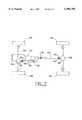
- FIG. 1is a top view of an electromagnetically controlled bi-directional one-way clutch apparatus in accordance with a preferred embodiment of the present invention.
- FIG. 2is a cross-sectional side view of the electromagnetically controlled bi-directional one-way clutch apparatus in accordance with the preferred embodiment of the present invention shown in FIG. 1.
- FIG. 3is a top view of a clutch strut for the electromagnetically controlled bi-directional one-way clutch apparatus in accordance with the preferred embodiment of the present invention shown in FIG. 1.
- FIG. 4is a front view of the clutch strut shown in FIG. 3 for the electromagnetically controlled bi-directional one-way clutch apparatus in accordance with the preferred embodiment of the present invention shown in FIG. 1.
- FIG. 5is a top view of a reactive/mating member for the electromagnetically controlled bi-directional one-way clutch apparatus in accordance with the preferred embodiment of the present invention shown in FIG. 1.
- FIG. 6a cross-sectional side view of the reactive/mating member shown in FIG. 5 for the electromagnetically controlled bi-directional one-way clutch apparatus in accordance with the preferred embodiment of the present invention shown in FIG. 1.
- FIG. 7is a top plan schematic view of a motor vehicle having a four-wheel drive system with a torque transfer case in accordance with the preferred embodiment of the present invention shown in FIG. 1.
- FIGS. 1 and 2is a top view and a cross-sectional side view, respectively, of electromagnetically controlled bi-directional one-way clutch apparatus 10 in accordance with a preferred embodiment of the present invention.
- electromagnetically controlled bi-directional one-way clutch apparatus 10 apparatusis preferably coupled with motor vehicle transaxle or transmission assembly 32 of conventional design which, in turn, is coupled to motor vehicle drive engine 34 also preferably of conventional design.
- Electromagnetically controlled bi-directional one-way clutch apparatus 10generally includes clutch plate 12 having one or more clutch struts 14, four (4) in the preferred embodiment of electromagnetically controlled bi-directional one-way clutch apparatus 10 shown in FIGS.
- Electromagnetically controlled bi-directional one-way clutch apparatus 10also includes reactive/mating member 20 which, referring to FIGS. 5 and 6, includes one or more clutch strut receiving pockets 22, four (4) in the preferred embodiment of reactive/mating member 20 shown in FIGS.
- Motor vehicle rear axle drive shaft 54has rearward end 56 connected to input shaft or yoke 58 of motor vehicle rear differential unit (not shown) via universal joint coupling 60 of conventional design.
- Motor vehicle rear differential unit 58is adapted to divide torque received from motor vehicle rear axle drive shaft 52 between rear wheels 62 of the motor vehicle.
- clutch struts 14preferably include magnets 24 and 26, most preferably permanent magnets, mounted in lower surface 28 thereof.
- clutch struts 14pivot according to the involved magnetic polarities allowing clutch struts 14 to activate electromagnetically controlled bi-directional one-way clutch apparatus 10 in a first rotational direction.
- clutch struts 14are made to pivot in the opposite direction and electromagnetically controlled bi-directional one-way clutch apparatus 10 is activated to work in a second rotational direction opposite to the first rotational direction.
- electromagnetically controlled bi-directional one-way clutch apparatus 10is selectively operational in both a first rotational direction, as well as in a second rotational direction opposite to that of the first rotational direction.
- electromagnetically actuating electromagnetically controlled bi-directional one way clutch apparatus 10one could control the rotational direction in which electromagnetically controlled bi-directional one way clutch apparatus 10 would work, limit the speed that electromagnetically controlled bi-directional one way clutch apparatus 10 will work in and make electromagnetically controlled bi-directional one way clutch apparatus 10 automatic by incorporating sensors and computer controls.
- Electromagnetically controlled bi-directional one way clutch apparatus 10has numerous applications in motor vehicle differentials and transfer cases.
- electromagnetically controlled bi-directional one way clutch apparatus 10could be controlled such that when a motor vehicle is in a forward drive gear, clutch struts 14 are pivoted to a first operational position and when the motor vehicle is put in a reverse drive gear, clutch struts 14 are pivoted to the second operational position.
- Application of electrical current to electric current coil 30 and the direction of flow of electrical current through electric current coil 30could be controlled by sensors designed to detect motor vehicle wheel slippage.
- electromagnetically controlled bi-directional one way clutch apparatus 10could be designed to be energized (in either direction) only above or below a predetermined motor vehicle speed.
- magnets 24 and 26permit electromagnetically controlled bi-directional one way clutch apparatus 10 to be controlled and placed in a first operational position, a second operational position or disengaged as desired.
Landscapes
- Engineering & Computer Science (AREA)
- General Engineering & Computer Science (AREA)
- Mechanical Engineering (AREA)
- Physics & Mathematics (AREA)
- Electromagnetism (AREA)
- Arrangement And Driving Of Transmission Devices (AREA)
- Arrangement And Mounting Of Devices That Control Transmission Of Motive Force (AREA)
Abstract
Description
Claims (20)
Priority Applications (4)
| Application Number | Priority Date | Filing Date | Title |
|---|---|---|---|
| US09/005,179US5996758A (en) | 1998-01-09 | 1998-01-09 | Electromagnetically controlled bi-directional one-way clutch apparatus |
| JP10377245AJPH11270590A (en) | 1998-01-09 | 1998-12-29 | Electromagneticlly controlled bidirectional one-way clutch device, and automobile transfer case and axle assembly with such clutch device |
| GB9900164AGB2337307B (en) | 1998-01-09 | 1999-01-05 | Electromagnetically controlled bi-directional one-way clutch appartus |
| DE19900453ADE19900453A1 (en) | 1998-01-09 | 1999-01-08 | Electromagnetically controlled bi-directional freewheeling clutch |
Applications Claiming Priority (1)
| Application Number | Priority Date | Filing Date | Title |
|---|---|---|---|
| US09/005,179US5996758A (en) | 1998-01-09 | 1998-01-09 | Electromagnetically controlled bi-directional one-way clutch apparatus |
Publications (1)
| Publication Number | Publication Date |
|---|---|
| US5996758Atrue US5996758A (en) | 1999-12-07 |
Family
ID=21714574
Family Applications (1)
| Application Number | Title | Priority Date | Filing Date |
|---|---|---|---|
| US09/005,179Expired - LifetimeUS5996758A (en) | 1998-01-09 | 1998-01-09 | Electromagnetically controlled bi-directional one-way clutch apparatus |
Country Status (4)
| Country | Link |
|---|---|
| US (1) | US5996758A (en) |
| JP (1) | JPH11270590A (en) |
| DE (1) | DE19900453A1 (en) |
| GB (1) | GB2337307B (en) |
Cited By (30)
| Publication number | Priority date | Publication date | Assignee | Title |
|---|---|---|---|---|
| EP1253041A3 (en)* | 2001-04-27 | 2003-08-13 | New Venture Gear, Inc. | On-demand four-wheel drive transfer case with controllable bi-directional clutch assembly |
| US6739440B1 (en) | 2003-06-06 | 2004-05-25 | Torque-Traction Technologies, Inc. | Bi-directional one-way clutch |
| US20050040000A1 (en)* | 2003-08-19 | 2005-02-24 | Kelley William R. | Clutch and synchronizer having permanent magnet actuators |
| US7363995B2 (en) | 2006-05-01 | 2008-04-29 | American Axle & Manufacturing, Inc. | Overrunning clutch and method of controlling engagement of same |
| US20110011694A1 (en)* | 2009-07-20 | 2011-01-20 | Gm Global Technology Operations, Inc. | Selectable one-way clutch |
| US20120103746A1 (en)* | 2010-10-28 | 2012-05-03 | Ford Global Technologies, Llc | Magnetically Actuated Mechanical Diode |
| US8403123B2 (en) | 2010-05-25 | 2013-03-26 | Ford Global Technologies, Llc | Magnetically actuated one-way clutch |
| US8418825B2 (en) | 2010-10-28 | 2013-04-16 | Ford Global Technologies, Llc | Magnetically actuated mechanical diode |
| US20140305761A1 (en)* | 2010-12-10 | 2014-10-16 | Means Industries, Inc. | Magnetic system for controlling the operating mode of an overrunning coupling assembly and overrunning coupling and magnetic control assembly having same |
| WO2014165387A3 (en)* | 2013-04-02 | 2015-04-09 | Warner Electric Technology Llc | Electromagnetic actuator for a bi-directional clutch |
| US9017209B1 (en) | 2013-12-31 | 2015-04-28 | Ingersoll-Rand Company | Power tools with reversible, self-shifting transmission |
| US9127730B2 (en) | 2012-10-17 | 2015-09-08 | Magna Powertrain Of America, Inc. | Electric actuator module for selectable clutch |
| US9222528B2 (en) | 2013-09-11 | 2015-12-29 | Ingersoll-Rand Company | Overrunning clutches |
| US9366298B2 (en) | 2010-10-28 | 2016-06-14 | Ford Global Technologies, Llc | Magnetically actuated clutch assembly |
| EP2817528A4 (en)* | 2012-02-23 | 2016-06-15 | Allison Transm Inc | Electromagnetically-actuated direction-sensing roller clutch |
| US9482294B2 (en) | 2014-02-19 | 2016-11-01 | Means Industries, Inc. | Coupling and control assembly including a sensor |
| US9562574B2 (en) | 2014-02-19 | 2017-02-07 | Means Industries, Inc. | Controllable coupling assembly and coupling member for use in the assembly |
| US9746040B2 (en) | 2012-02-23 | 2017-08-29 | Allison Transmission, Inc. | Mechanically-actuated direction-sensing roller clutch |
| EP2676045A4 (en)* | 2011-02-14 | 2018-03-07 | Means Industries, Inc. | Electromechanical assembly to control the operating mode of a coupling apparatus |
| EP2649339A4 (en)* | 2010-12-10 | 2018-03-14 | Means Industries, Inc. | Electromechanically actuated coupling and control assembly |
| US10024370B1 (en) | 2017-01-13 | 2018-07-17 | Ford Global Technologies, Llc | Hybrid transmission having electro-magnetically actuated pawl clutch |
| CN108468726A (en)* | 2018-06-21 | 2018-08-31 | 朱东明 | A kind of innovative automatic transmission |
| US10434863B2 (en)* | 2014-08-22 | 2019-10-08 | Borgwarner Inc. | Multimode clutch for through-the-road hybrid vehicle |
| CN110630654A (en)* | 2019-09-20 | 2019-12-31 | 金怀璧 | Electromagnetic clutch |
| EP3611395A1 (en) | 2015-04-01 | 2020-02-19 | Means Industries, Inc. | Electronic vehicular transmission, controllable coupling assembly and coupling member for use in the assembly |
| WO2020117880A1 (en)* | 2018-12-04 | 2020-06-11 | Means Industries, Inc. | Electromagnetic system for controlling the operating mode of a non-friction coupling assembly and coupling and magnetic control assembly having same |
| US10724582B2 (en) | 2018-05-14 | 2020-07-28 | Ford Global Technologies, Llc | Hybrid transmission having electro-magnetically actuated pawl clutch |
| US11346404B2 (en) | 2018-10-09 | 2022-05-31 | Means Industries, Inc. | Coupling and control assembly for use in a motor vehicle |
| CN115593619A (en)* | 2016-12-07 | 2023-01-13 | 威斯克航空有限责任公司(Us) | Lifting fan position locking mechanism |
| RU216805U1 (en)* | 2022-05-25 | 2023-03-02 | Евгений Викторович Пугачев | Freewheel |
Families Citing this family (3)
| Publication number | Priority date | Publication date | Assignee | Title |
|---|---|---|---|---|
| CN103591182B (en)* | 2012-08-13 | 2017-02-08 | 深圳市奥科伟业科技发展有限公司 | Bi-directional overrun clutch and separation control method thereof |
| DE102013002987A1 (en) | 2013-02-21 | 2014-08-21 | Iwis Motorsysteme Gmbh & Co. Kg | Freewheel device for coupling crankshaft in gear unit of vehicle engine, has clamping element that is moved into coupling position from release position due to force and magnetic flux on clamping element by electromagnetic device |
| DE102019205452A1 (en)* | 2019-04-16 | 2020-10-22 | Zf Friedrichshafen Ag | Switchable freewheel |
Citations (19)
| Publication number | Priority date | Publication date | Assignee | Title |
|---|---|---|---|---|
| US33742A (en)* | 1861-11-19 | Improved means of attaching traces to carriages | ||
| US2784820A (en)* | 1952-06-30 | 1957-03-12 | Frank G Clark | Reversing power transmission mechanism, especially for garden tractors |
| US2844743A (en)* | 1957-05-28 | 1958-07-22 | James P Watson | Detent mechanisms |
| US2866109A (en)* | 1958-12-23 | Axial flux electromagnetic machinery | ||
| US3249185A (en)* | 1963-03-19 | 1966-05-03 | Walter H Moorhead | One way reversible clutch |
| US3801033A (en)* | 1971-12-17 | 1974-04-02 | Rca Corp | Apparatus for easily engaging, disengaging and locking load to rotatable driving element |
| US3831692A (en)* | 1972-10-17 | 1974-08-27 | Durst Corp | Drive tower for circular irrigation system |
| US3907083A (en)* | 1974-07-22 | 1975-09-23 | Berthold L Nieder | Controllable bi-directional coupling device |
| US4222473A (en)* | 1979-03-05 | 1980-09-16 | General Motors Corporation | Four way pawl clutch |
| US4781078A (en)* | 1987-02-02 | 1988-11-01 | Dana Corporation | Locking differential with electromagnetic actuated clutch |
| US5025902A (en)* | 1990-01-04 | 1991-06-25 | Aichi Kikai Kogyo Kabushiki Kaisha | Bidirectional differential clutch |
| USRE33742E (en) | 1987-02-02 | 1991-11-12 | Dana Corporation | Locking differential with electromagnetic actuated clutch |
| US5070978A (en)* | 1990-04-19 | 1991-12-10 | Pires Paul B | One way drive device |
| US5135086A (en)* | 1990-08-17 | 1992-08-04 | Star Precision Tools, Inc. | Assembly tool with rapid release electromagnetic clutch |
| US5159522A (en)* | 1990-02-27 | 1992-10-27 | Dana Corporation | Electric clutch actuator |
| US5199325A (en)* | 1991-09-12 | 1993-04-06 | Dana Corporation | Electronic shift or clutch actuator for a vehicle transmission |
| US5503261A (en)* | 1994-07-15 | 1996-04-02 | Automotive Concepts Technology | Bi-directional centrifugal clutch |
| US5518094A (en)* | 1994-07-22 | 1996-05-21 | Honeybee Robotics, Inc. | Clutch/brake having rectangular-area-contact 3D locking sprags |
| US5551262A (en)* | 1994-02-28 | 1996-09-03 | Samsung Electronics Co., Ltd. | Power transmission apparatus of a washing machine |
Family Cites Families (3)
| Publication number | Priority date | Publication date | Assignee | Title |
|---|---|---|---|---|
| GB614738A (en)* | 1945-07-24 | 1948-12-22 | British Thomson Houston Co Ltd | Improvements in and relating to one-way drives and detents with magnetic locking |
| GB627087A (en)* | 1946-02-26 | 1949-07-28 | Citroen Sa Andre | A shaft synchronizing and coupling system |
| CN1074659A (en)* | 1992-01-25 | 1993-07-28 | 高兴龙 | Vehicle high-effciency and energy-saving multi-function system |
- 1998
- 1998-01-09USUS09/005,179patent/US5996758A/ennot_activeExpired - Lifetime
- 1998-12-29JPJP10377245Apatent/JPH11270590A/enactivePending
- 1999
- 1999-01-05GBGB9900164Apatent/GB2337307B/ennot_activeExpired - Fee Related
- 1999-01-08DEDE19900453Apatent/DE19900453A1/ennot_activeWithdrawn
Patent Citations (19)
| Publication number | Priority date | Publication date | Assignee | Title |
|---|---|---|---|---|
| US33742A (en)* | 1861-11-19 | Improved means of attaching traces to carriages | ||
| US2866109A (en)* | 1958-12-23 | Axial flux electromagnetic machinery | ||
| US2784820A (en)* | 1952-06-30 | 1957-03-12 | Frank G Clark | Reversing power transmission mechanism, especially for garden tractors |
| US2844743A (en)* | 1957-05-28 | 1958-07-22 | James P Watson | Detent mechanisms |
| US3249185A (en)* | 1963-03-19 | 1966-05-03 | Walter H Moorhead | One way reversible clutch |
| US3801033A (en)* | 1971-12-17 | 1974-04-02 | Rca Corp | Apparatus for easily engaging, disengaging and locking load to rotatable driving element |
| US3831692A (en)* | 1972-10-17 | 1974-08-27 | Durst Corp | Drive tower for circular irrigation system |
| US3907083A (en)* | 1974-07-22 | 1975-09-23 | Berthold L Nieder | Controllable bi-directional coupling device |
| US4222473A (en)* | 1979-03-05 | 1980-09-16 | General Motors Corporation | Four way pawl clutch |
| US4781078A (en)* | 1987-02-02 | 1988-11-01 | Dana Corporation | Locking differential with electromagnetic actuated clutch |
| USRE33742E (en) | 1987-02-02 | 1991-11-12 | Dana Corporation | Locking differential with electromagnetic actuated clutch |
| US5025902A (en)* | 1990-01-04 | 1991-06-25 | Aichi Kikai Kogyo Kabushiki Kaisha | Bidirectional differential clutch |
| US5159522A (en)* | 1990-02-27 | 1992-10-27 | Dana Corporation | Electric clutch actuator |
| US5070978A (en)* | 1990-04-19 | 1991-12-10 | Pires Paul B | One way drive device |
| US5135086A (en)* | 1990-08-17 | 1992-08-04 | Star Precision Tools, Inc. | Assembly tool with rapid release electromagnetic clutch |
| US5199325A (en)* | 1991-09-12 | 1993-04-06 | Dana Corporation | Electronic shift or clutch actuator for a vehicle transmission |
| US5551262A (en)* | 1994-02-28 | 1996-09-03 | Samsung Electronics Co., Ltd. | Power transmission apparatus of a washing machine |
| US5503261A (en)* | 1994-07-15 | 1996-04-02 | Automotive Concepts Technology | Bi-directional centrifugal clutch |
| US5518094A (en)* | 1994-07-22 | 1996-05-21 | Honeybee Robotics, Inc. | Clutch/brake having rectangular-area-contact 3D locking sprags |
Cited By (42)
| Publication number | Priority date | Publication date | Assignee | Title |
|---|---|---|---|---|
| EP1253041A3 (en)* | 2001-04-27 | 2003-08-13 | New Venture Gear, Inc. | On-demand four-wheel drive transfer case with controllable bi-directional clutch assembly |
| US6739440B1 (en) | 2003-06-06 | 2004-05-25 | Torque-Traction Technologies, Inc. | Bi-directional one-way clutch |
| US20050040000A1 (en)* | 2003-08-19 | 2005-02-24 | Kelley William R. | Clutch and synchronizer having permanent magnet actuators |
| US7086515B2 (en)* | 2003-08-19 | 2006-08-08 | Borgwarner Inc. | Clutch and synchronizer having permanent magnet actuators |
| US7363995B2 (en) | 2006-05-01 | 2008-04-29 | American Axle & Manufacturing, Inc. | Overrunning clutch and method of controlling engagement of same |
| US20110011694A1 (en)* | 2009-07-20 | 2011-01-20 | Gm Global Technology Operations, Inc. | Selectable one-way clutch |
| US8276725B2 (en)* | 2009-07-20 | 2012-10-02 | GM Global Technology Operations LC | Selectable one-way clutch |
| US8403123B2 (en) | 2010-05-25 | 2013-03-26 | Ford Global Technologies, Llc | Magnetically actuated one-way clutch |
| US9366298B2 (en) | 2010-10-28 | 2016-06-14 | Ford Global Technologies, Llc | Magnetically actuated clutch assembly |
| US20120103746A1 (en)* | 2010-10-28 | 2012-05-03 | Ford Global Technologies, Llc | Magnetically Actuated Mechanical Diode |
| US8418825B2 (en) | 2010-10-28 | 2013-04-16 | Ford Global Technologies, Llc | Magnetically actuated mechanical diode |
| US9915301B2 (en)* | 2010-10-28 | 2018-03-13 | Ford Global Technologies, Llc | Magnetically actuated mechanical diode |
| EP2649339A4 (en)* | 2010-12-10 | 2018-03-14 | Means Industries, Inc. | Electromechanically actuated coupling and control assembly |
| US9234552B2 (en)* | 2010-12-10 | 2016-01-12 | Means Industries, Inc. | Magnetic system for controlling the operating mode of an overrunning coupling assembly and overrunning coupling and magnetic control assembly having same |
| US20140305761A1 (en)* | 2010-12-10 | 2014-10-16 | Means Industries, Inc. | Magnetic system for controlling the operating mode of an overrunning coupling assembly and overrunning coupling and magnetic control assembly having same |
| EP2676045A4 (en)* | 2011-02-14 | 2018-03-07 | Means Industries, Inc. | Electromechanical assembly to control the operating mode of a coupling apparatus |
| EP2817528A4 (en)* | 2012-02-23 | 2016-06-15 | Allison Transm Inc | Electromagnetically-actuated direction-sensing roller clutch |
| US9746040B2 (en) | 2012-02-23 | 2017-08-29 | Allison Transmission, Inc. | Mechanically-actuated direction-sensing roller clutch |
| US9856929B2 (en) | 2012-02-23 | 2018-01-02 | Allison Transmission, Inc. | Electromagnetically-actuated direction-sensing roller clutch |
| US9739322B2 (en) | 2012-10-17 | 2017-08-22 | Magna Powertrain Of America, Inc. | Electric actuator module for selectable clutch |
| US9127730B2 (en) | 2012-10-17 | 2015-09-08 | Magna Powertrain Of America, Inc. | Electric actuator module for selectable clutch |
| CN105378320A (en)* | 2013-04-02 | 2016-03-02 | 华纳电气科技有限公司 | Electromagnetic actuator for a bi-directional clutch |
| US9097299B2 (en) | 2013-04-02 | 2015-08-04 | Warner Electric Technology Llc | Electromagnetic actuator for a bi-directional clutch |
| WO2014165387A3 (en)* | 2013-04-02 | 2015-04-09 | Warner Electric Technology Llc | Electromagnetic actuator for a bi-directional clutch |
| RU2614434C1 (en)* | 2013-04-02 | 2017-03-28 | Уорнер Электрик Текнолоджи Ллк | Reverse clutch (versions) |
| CN105378320B (en)* | 2013-04-02 | 2017-10-31 | 华纳电气科技有限公司 | Electromagnetic actuator for bidirectional clutch |
| US9222528B2 (en) | 2013-09-11 | 2015-12-29 | Ingersoll-Rand Company | Overrunning clutches |
| US9017209B1 (en) | 2013-12-31 | 2015-04-28 | Ingersoll-Rand Company | Power tools with reversible, self-shifting transmission |
| US9482294B2 (en) | 2014-02-19 | 2016-11-01 | Means Industries, Inc. | Coupling and control assembly including a sensor |
| US9562574B2 (en) | 2014-02-19 | 2017-02-07 | Means Industries, Inc. | Controllable coupling assembly and coupling member for use in the assembly |
| US10434863B2 (en)* | 2014-08-22 | 2019-10-08 | Borgwarner Inc. | Multimode clutch for through-the-road hybrid vehicle |
| EP3611395A1 (en) | 2015-04-01 | 2020-02-19 | Means Industries, Inc. | Electronic vehicular transmission, controllable coupling assembly and coupling member for use in the assembly |
| CN115593619A (en)* | 2016-12-07 | 2023-01-13 | 威斯克航空有限责任公司(Us) | Lifting fan position locking mechanism |
| US10024370B1 (en) | 2017-01-13 | 2018-07-17 | Ford Global Technologies, Llc | Hybrid transmission having electro-magnetically actuated pawl clutch |
| US10724582B2 (en) | 2018-05-14 | 2020-07-28 | Ford Global Technologies, Llc | Hybrid transmission having electro-magnetically actuated pawl clutch |
| CN108468726A (en)* | 2018-06-21 | 2018-08-31 | 朱东明 | A kind of innovative automatic transmission |
| US11346404B2 (en) | 2018-10-09 | 2022-05-31 | Means Industries, Inc. | Coupling and control assembly for use in a motor vehicle |
| WO2020117880A1 (en)* | 2018-12-04 | 2020-06-11 | Means Industries, Inc. | Electromagnetic system for controlling the operating mode of a non-friction coupling assembly and coupling and magnetic control assembly having same |
| DE112019006036T5 (en) | 2018-12-04 | 2021-09-30 | Means Industries, Inc. | Electromagnetic system for controlling the mode of operation of a frictionless clutch assembly and clutch and magnetic control assembly with the same |
| US10995803B2 (en) | 2018-12-04 | 2021-05-04 | Means Industries, Inc. | Electromagnetic system for controlling the operating mode of a non friction coupling assembly and coupling and magnetic control assembly having same |
| CN110630654A (en)* | 2019-09-20 | 2019-12-31 | 金怀璧 | Electromagnetic clutch |
| RU216805U1 (en)* | 2022-05-25 | 2023-03-02 | Евгений Викторович Пугачев | Freewheel |
Also Published As
| Publication number | Publication date |
|---|---|
| GB2337307B (en) | 2002-06-12 |
| GB9900164D0 (en) | 1999-02-24 |
| JPH11270590A (en) | 1999-10-05 |
| GB2337307A (en) | 1999-11-17 |
| DE19900453A1 (en) | 1999-07-15 |
Similar Documents
| Publication | Publication Date | Title |
|---|---|---|
| US5996758A (en) | Electromagnetically controlled bi-directional one-way clutch apparatus | |
| US5738604A (en) | Four-wheel motor vehicle drive transfer case with limited differentiation | |
| EP0043237B1 (en) | Vehicle drive control system | |
| US6739440B1 (en) | Bi-directional one-way clutch | |
| US6099430A (en) | Clutching actuator for clutch control system in a drive line apparatus | |
| US6540640B2 (en) | Power on demand differential | |
| US5007498A (en) | Driving assembly | |
| US11098794B2 (en) | Locking angle gear box | |
| US5314039A (en) | Drive assembly for a four wheel drive vehicle, having a disconnectable viscous coupling | |
| US5247443A (en) | Electronic control for vehicle four wheel drive system | |
| US5355748A (en) | Rotation transmitting device for an interaxle gearless differential | |
| JPH1144330A (en) | Two-direction oneway clutch | |
| US6176359B1 (en) | Bi-directional overrunning clutch | |
| GB2341829A (en) | Four-wheel drive system for vehicles | |
| US6071207A (en) | Full-time transfer case with mode shift arrangement | |
| US20030079955A1 (en) | Power transmission system for an automatically engaging four-wheel drive vehicle | |
| US6550594B1 (en) | Active pin slot index system for a bidirectional clutch | |
| EP0333095A1 (en) | Power transmission apparatus | |
| US20180319278A1 (en) | Tandem Axle With Disconnect Coast | |
| WO2018204578A1 (en) | Tandem axle with disconnect coast | |
| CN117507852A (en) | Distributed electric drive system and control method thereof | |
| US6626053B2 (en) | Motor vehicle torque transfer case pump drive | |
| US5542514A (en) | Rotational transmission device | |
| JP2004359132A (en) | Driving force transmission system | |
| KR100624886B1 (en) | Electronic coupling of FF type 4WD |
Legal Events
| Date | Code | Title | Description |
|---|---|---|---|
| AS | Assignment | Owner name:DANA CORPORATION, OHIO Free format text:ASSIGNMENT OF ASSIGNORS INTEREST;ASSIGNOR:BAXTER, RALPH W., JR.;REEL/FRAME:008962/0950 Effective date:19980106 | |
| STCF | Information on status: patent grant | Free format text:PATENTED CASE | |
| AS | Assignment | Owner name:SPICER TECHNOLOGY, INC., INDIANA Free format text:ASSIGNMENT OF ASSIGNORS INTEREST;ASSIGNOR:DANA CORPORATION;REEL/FRAME:010609/0413 Effective date:19991228 | |
| AS | Assignment | Owner name:SPICER TECHNOLOGY, INC., INDIANA Free format text:ASSIGNMENT OF ASSIGNORS INTEREST;ASSIGNOR:DANA CORPORATION;REEL/FRAME:010776/0646 Effective date:19991228 | |
| FEPP | Fee payment procedure | Free format text:PAYOR NUMBER ASSIGNED (ORIGINAL EVENT CODE: ASPN); ENTITY STATUS OF PATENT OWNER: LARGE ENTITY | |
| AS | Assignment | Owner name:TORQUE-TRACTION TECHNOLOGIES, INC., OHIO Free format text:MERGER /CHANGE OF NAME;ASSIGNORS:SPICER TECHNOLOGY, INC.;SPICER DRIVESHAFT, INC.;REEL/FRAME:014646/0285 Effective date:20021231 Owner name:TORQUE-TRACTION TECHNOLOGIES, INC., OHIO Free format text:MERGER AND CHANGE OF NAME;ASSIGNORS:SPICER TECHNOLOGY, INC.;SPICER DRIVESHAFT, INC.;REEL/FRAME:013943/0214 Effective date:20021231 | |
| FPAY | Fee payment | Year of fee payment:4 | |
| AS | Assignment | Owner name:TORQUE-TRACTION TECHNOLOGIES LLC, OHIO Free format text:MERGER;ASSIGNOR:TORQUE-TRACTION TECHNOLOGY, INC.;REEL/FRAME:017240/0209 Effective date:20060101 | |
| FPAY | Fee payment | Year of fee payment:8 | |
| AS | Assignment | Owner name:DANA AUTOMOTIVE SYSTEMS GROUP, LLC, OHIO Free format text:ASSIGNMENT OF ASSIGNORS INTEREST;ASSIGNOR:TORQUE-TRACTION TECHNOLOGIES, LLC;REEL/FRAME:020518/0949 Effective date:20080131 Owner name:DANA AUTOMOTIVE SYSTEMS GROUP, LLC,OHIO Free format text:ASSIGNMENT OF ASSIGNORS INTEREST;ASSIGNOR:TORQUE-TRACTION TECHNOLOGIES, LLC;REEL/FRAME:020518/0949 Effective date:20080131 | |
| AS | Assignment | Owner name:CITICORP USA, INC., NEW YORK Free format text:INTELLECTUAL PROPERTY REVOLVING FACILITY SECURITY AGREEMENT;ASSIGNORS:DANA HOLDING CORPORATION;DANA LIMITED;DANA AUTOMOTIVE SYSTEMS GROUP, LLC;AND OTHERS;REEL/FRAME:020859/0249 Effective date:20080131 Owner name:CITICORP USA, INC.,NEW YORK Free format text:INTELLECTUAL PROPERTY REVOLVING FACILITY SECURITY AGREEMENT;ASSIGNORS:DANA HOLDING CORPORATION;DANA LIMITED;DANA AUTOMOTIVE SYSTEMS GROUP, LLC;AND OTHERS;REEL/FRAME:020859/0249 Effective date:20080131 Owner name:CITICORP USA, INC., NEW YORK Free format text:INTELLECTUAL PROPERTY TERM FACILITY SECURITY AGREEMENT;ASSIGNORS:DANA HOLDING CORPORATION;DANA LIMITED;DANA AUTOMOTIVE SYSTEMS GROUP, LLC;AND OTHERS;REEL/FRAME:020859/0359 Effective date:20080131 Owner name:CITICORP USA, INC.,NEW YORK Free format text:INTELLECTUAL PROPERTY TERM FACILITY SECURITY AGREEMENT;ASSIGNORS:DANA HOLDING CORPORATION;DANA LIMITED;DANA AUTOMOTIVE SYSTEMS GROUP, LLC;AND OTHERS;REEL/FRAME:020859/0359 Effective date:20080131 | |
| FPAY | Fee payment | Year of fee payment:12 |