US5996378A - Knitted textile fabric with integrated fluid-containing or -conveying tubular segments - Google Patents
Knitted textile fabric with integrated fluid-containing or -conveying tubular segmentsDownload PDFInfo
- Publication number
- US5996378A US5996378AUS09/082,019US8201998AUS5996378AUS 5996378 AUS5996378 AUS 5996378AUS 8201998 AUS8201998 AUS 8201998AUS 5996378 AUS5996378 AUS 5996378A
- Authority
- US
- United States
- Prior art keywords
- textile fabric
- knitted
- knitted textile
- fabric
- fabric according
- Prior art date
- Legal status (The legal status is an assumption and is not a legal conclusion. Google has not performed a legal analysis and makes no representation as to the accuracy of the status listed.)
- Expired - Fee Related
Links
- 239000004744fabricSubstances0.000titleclaimsabstractdescription98
- 239000004753textileSubstances0.000titleclaimsabstractdescription29
- 239000012530fluidSubstances0.000titleclaimsdescription9
- 238000009940knittingMethods0.000description20
- 238000003780insertionMethods0.000description10
- 230000037431insertionEffects0.000description9
- 238000010276constructionMethods0.000description7
- 239000000758substrateSubstances0.000description5
- 230000015572biosynthetic processEffects0.000description4
- 239000002131composite materialSubstances0.000description4
- 238000010438heat treatmentMethods0.000description4
- 238000001816coolingMethods0.000description3
- 238000010586diagramMethods0.000description3
- 238000000034methodMethods0.000description3
- 230000006978adaptationEffects0.000description2
- 239000000470constituentSubstances0.000description2
- 238000005188flotationMethods0.000description2
- 239000006260foamSubstances0.000description2
- 238000012986modificationMethods0.000description2
- 230000004048modificationEffects0.000description2
- 230000000717retained effectEffects0.000description2
- 239000000126substanceSubstances0.000description2
- 239000004677NylonSubstances0.000description1
- 230000003466anti-cipated effectEffects0.000description1
- 239000012809cooling fluidSubstances0.000description1
- 210000000887faceAnatomy0.000description1
- 230000001788irregularEffects0.000description1
- 238000004519manufacturing processMethods0.000description1
- 239000000463materialSubstances0.000description1
- 229920001778nylonPolymers0.000description1
- 229920000728polyesterPolymers0.000description1
- 239000012815thermoplastic materialSubstances0.000description1
Images

Classifications
- D—TEXTILES; PAPER
- D04—BRAIDING; LACE-MAKING; KNITTING; TRIMMINGS; NON-WOVEN FABRICS
- D04B—KNITTING
- D04B21/00—Warp knitting processes for the production of fabrics or articles not dependent on the use of particular machines; Fabrics or articles defined by such processes
- D04B21/20—Warp knitting processes for the production of fabrics or articles not dependent on the use of particular machines; Fabrics or articles defined by such processes specially adapted for knitting articles of particular configuration
- D—TEXTILES; PAPER
- D10—INDEXING SCHEME ASSOCIATED WITH SUBLASSES OF SECTION D, RELATING TO TEXTILES
- D10B—INDEXING SCHEME ASSOCIATED WITH SUBLASSES OF SECTION D, RELATING TO TEXTILES
- D10B2403/00—Details of fabric structure established in the fabric forming process
- D10B2403/02—Cross-sectional features
- D10B2403/024—Fabric incorporating additional compounds
- D10B2403/0243—Fabric incorporating additional compounds enhancing functional properties
- D—TEXTILES; PAPER
- D10—INDEXING SCHEME ASSOCIATED WITH SUBLASSES OF SECTION D, RELATING TO TEXTILES
- D10B—INDEXING SCHEME ASSOCIATED WITH SUBLASSES OF SECTION D, RELATING TO TEXTILES
- D10B2505/00—Industrial
- D10B2505/08—Upholstery, mattresses
- Y—GENERAL TAGGING OF NEW TECHNOLOGICAL DEVELOPMENTS; GENERAL TAGGING OF CROSS-SECTIONAL TECHNOLOGIES SPANNING OVER SEVERAL SECTIONS OF THE IPC; TECHNICAL SUBJECTS COVERED BY FORMER USPC CROSS-REFERENCE ART COLLECTIONS [XRACs] AND DIGESTS
- Y10—TECHNICAL SUBJECTS COVERED BY FORMER USPC
- Y10T—TECHNICAL SUBJECTS COVERED BY FORMER US CLASSIFICATION
- Y10T442/00—Fabric [woven, knitted, or nonwoven textile or cloth, etc.]
- Y10T442/40—Knit fabric [i.e., knit strand or strip material]
- Y10T442/425—Including strand which is of specific structural definition
- Y10T442/431—Cross-sectional configuration of strand material is specified
Definitions
- the present inventionrelates generally to textile fabrics, especially knitted textile fabrics, and relates more particularly to a novel knitted textile fabric having elongate hollow tubular segments integrated into the fabric structure for use in containing or conveying fluids across the fabric structure.
- Tubes and pipes of varying shapes and sizesare commonly used for containing and conveying fluids, and especially for conveying heating and/or cooling fluids.
- such tubes or pipesmay be incorporated into a substrate or the like for structural support and to retain the tubes or pipes in a desired position, orientation or relationship.
- One means of accomplishing the cooling/heating of an automobile seatis to incorporate fluid-carrying tubes, pipes or passageways into the seat structure.
- such tubes, pipes or passagewaysmay be formed or contained within the foam cushioning commonly utilized in such seats.
- a more particular object of the present inventionis to form such a composite product utilizing a knitted fabric structure, particularly a warp knitted fabric structure.
- a further objectis to provide a means for selective disposition and orientation of such pipes or tubes in the fabric structure, either in a direction longitudinally along the fabric or transversely across the fabric.
- a knitted textile fabricbasically comprising one or more yarns formed into inter-looped stitches defining a fabric structure having a longitudinal extent and a transverse extent wherein the yarn stitches are aligned longitudinally in a plurality of essentially parallel wales and transversely in a plurality of essentially parallel courses perpendicular to the wales.
- a plurality of elongate hollow tubular segmentsare integrated with such yarn into the fabric structure in spaced essentially parallel relation to one another such that the tubular segments are adapted for carrying a fluid, e.g., by connecting the respective ends of the tubular segments to fluid-distributing intake and exhaust manifolds for conveying a fluid across the fabric structure.
- the fabric structuremay be a warp knitted structure, preferably formed of a dimensionally stable stitch pattern, e.g., an at least two-bar knitted structure fabricated of two sets of warp yarns one formed in a walewise chain stitch pattern (such as a repeating 0-1, 1-0 pattern) and the other formed in a coursewise inlay pattern (such as a 4-4, 0-0 pattern), with an additional set of weft inserted yarns also extending coursewise.
- a dimensionally stable stitch patterne.g., an at least two-bar knitted structure fabricated of two sets of warp yarns one formed in a walewise chain stitch pattern (such as a repeating 0-1, 1-0 pattern) and the other formed in a coursewise inlay pattern (such as a 4-4, 0-0 pattern), with an additional set of weft inserted yarns also extending coursewise.
- the stitchesare omitted from selected spaced wales and the tubular segments are disposed longitudinally within these selected spaced wales and retained therein by the yarns of the fabric structure, whereby the tubular segments extend walewise (i.e. longitudinally) along the length of the knitted fabric.
- the tubular segmentsare weft inserted coursewise within the stitches of selected spaced courses, thereby to extend transversely across the width of the fabric structure.
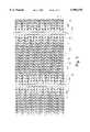
- FIG. 1is a schematic diagram depicting the fabric structure, and the individual stitch patterns for the constituent yarns thereof, in one variation of the preferred warp knitted embodiment of the textile fabric of the present invention.
- FIG. 2is another schematic diagram, similar to FIG. 1, depicting the fabric structure and the individual stitch patterns of the constituent yarns thereof, in another variation of the preferred warp knitted embodiment of the textile fabric of the present invention.
- the preferred embodiment of the fabric of the present inventionis produced on a warp knitting machine which may be of any conventional type of an at least two-bar construction having two or more yarn guide bars and a needle bar, e.g., a conventional tricot warp knitting machine.
- a warp knitting machinewhich may be of any conventional type of an at least two-bar construction having two or more yarn guide bars and a needle bar, e.g., a conventional tricot warp knitting machine.
- the construction and operation of such machineare well known in the warp knitting art and need not herein be specifically described and illustrated.
- the yarn guide bars of a two-bar knitting machineare identified as “top” and “bottom” guide bars and the yarn guide bars of a three-bar knitting machine are identified as “top,” “middle” and “bottom” guide bars for references purposes only and not by way of limitation.
- FIG. 1 of the accompanying drawingsone particular embodiment of the present textile fabric is illustrated as preferably warp knitted of a three-bar construction on a three-bar weft insertion warp knitting machine.
- the needle bar of the warp knitting machinecarries a series of aligned knitting needles, while each guide bar of the machine carries a series of guide eyes, the needle and guide bars preferably having the same gauge, i.e., the same number of needles and guide eyes per inch.
- the top guide bar of the machineis utilized for feeding the elongate tubes T and therefore is equipped with tube guide elements (not shown) at selected spacings along the guide bar. Any desired spacing of the tube guides may be utilized and the spacings may be regular or irregular.
- the tubes Tare fed at a regular spacing of sixteen intervening needles, merely for purposes of illustration and by way of example.
- an appropriate number of needlesare removed from the needle bar of the machine to accommodate and avoid interference with the tubes T.
- two needlesare shown to have been removed for each tube T, but it is to be understood that the number of removed needles may be more or less depending upon the gauge of the knitting machine and the size and spacing of the tubes.
- the middle guide baris threaded with a set of inlay yarns 12 delivered from a warp beam (not shown) through substantially every guide eye except two guide eyes corresponding to each omitted pair of needles and two additional guide eyes spaced one needle leftwardly (as viewed in FIG. 1) therefrom.
- the bottom guide baris threaded with a set of ground yarns 10 supplied from another warp beam (also not shown) on every guide eye except two guide eyes corresponding to each pair of needles omitted from the needle bar.
- the warp knitting machineadditionally includes a weft insertion device supplied with a filling yarn 14 to be inserted across the needles of the needle bar as the fabric is formed, as more fully explained below.
- the yarnsmay be suitable for use as the ground, inlay and filling yarns, it is preferred that the yarns be relatively inelastic so as to contribute, along with the stitch construction of the fabric, to the dimensional stability of the fabric.
- any of a variety of conventional multifilament synthetic yarns, particularly polyester and nylon yarns,would be suitable for use as any or all of the ground, inlay and filling yarns.
- the denier of the yarnsmay vary depending upon the desired weight and stiffness of the fabric and its intended application or end use.
- tubes Tmay likewise be utilized according to the intended use and application thereof, but in most cases it is contemplated that tubes of a thermo-plastic material sufficiently flexible to perform in the knitting process but otherwise sufficiently stiff and rigid to resist deformation and collapse in use will be preferred.
- FIG. 1the stitch constructions of the ground, inlay and filling yarns 10,12,14, as carried out by the respective lateral traversing movements of the guide bars of the knitting machine and the simultaneous action of the weft insertion device according to one preferred embodiment of the present fabric, are illustrated in a traditional dot or point diagram format, wherein the individual points 15 represent the needles of the needle bar of the knitting machine in the formation of several successive fabric courses C across several successive fabric wales W.
- the bottom (or back) guide bar of the warp knitting machinemanipulates the set of ground yarns 10 as they are fed from their respective warp beam to traverse laterally back and forth relative to the needle bar of the machine to stitch the ground yarns 10 on every needle 15 present in the needle bar of the machine in a repeating 0-1, 1-0 chain stitch pattern.
- the location of the needles which have been removed from the needle barare identified at points 15A, it being understood that such points 15A represent missing needles and not active present needles.
- the middle guide barsimultaneously manipulates the set of inlay yarns 12 as they are fed from their respective warp beam to traverse back and forth relative to the needle bar by a travel distance of four needle locations 15, 15A to lay the yarns 12 without stitch formation about the needles 15 in a repeating 4-4, 0-0 inlay pattern.
- the weft insertion device of the knitting machineis activated during the formation of each successive fabric course to insert the filling yarn 14 weftwise through the chain stitch needle loops of the ground yarn 10.
- the top guide barserves to insert the spaced tubes T between the inlay yarns 12 and the filling yarns 14 along the length of the fabric in the spaced areas of the missing needles 15A.
- the ground, inlay and filling yarns 10,12,14are interknitted with one another by formation of chain stitch needle loops 10n of the ground yarns 10 longitudinally within each wale W of each course C of the resultant fabric except the wales W1 corresponding to the removed needle locations 15A, with the inlay yarns 12 and the filling yarn 14 extending transversely, i.e. coursewise, through each needle loop 12n of the ground yarns 12 in each wale W and across the wales W1 of each course C.
- the inlay pattern followed by the inlay yarns 12causes each of the yarns to traverse coursewise back and across four wales W, W1 in each course C, while each filling yarn 14 extends the full width of the fabric in each course C.
- the inlay and filling yarns 12,14appear at opposite faces of the resultant fabric and therefore capture the tubes T therebetween within each spaced pair of wales W1.
- the respective stitch and inlay patterns followed by the yarns 10,12,14cooperate to integrate one another into a fabric structure having a high degree of dimensional stability and integrity, i.e. a high resistance to stretchability, the chain stitch pattern of the ground yarns 10 resisting walewise stretchability while the coursewise orientations of the inlay and filling yarns resist coursewise stretchability.
- the tubes Tare therefore securely held in a walewise essentially linear orientation in spaced parallel relation to one another.
- FIG. 2An alternative embodiment of the present textile fabric is shown in FIG. 2.
- the fabric of FIG. 2is similar to that of FIG. 1 in that the fabric structure comprises ground, inlay and filling yarns 110,112,114 interknitted with one another in the identical stitch, inlay and weft insertion patterns as the above-described fabric illustrated in FIG. 1.
- the fabric of FIG. 2differs from that of FIG. 1 in that the tubes T are inserted coursewise utilizing the weft insertion device, whereby this fabric may be formed on a two-bar weft-insertion warp knitting machine.
- every guide eye in the bottom guide barcarries a ground yarn 110 and every guide eye in the top guide bar carries an inlay yarn 112, whereby the ground and inlay yarns 110,112 are formed in every wale W of every course C.
- the filling yarn 14 in this fabricis inserted weftwise in every course C, except selected spaced courses C1, in which courses C1 the tubes T are inserted weftwise by the weft insertion device to extend coursewise through the needle loops/10n of the ground yarns/10 within such courses C1 for the full transverse width of the fabric.
- the selection of yarn type, yarn size, machine gauge, tube size and type, etc.may be varied in similar manner and according to essentially the same parameters and criteria as discussed above in connection with the fabric of FIG. 1.
- the stitch, inlay and weft insertion patterns followed by the ground, inlay and filling yarns 110,112,114form a dimensionally stable fabric structure in which the tubes T are securely retained coursewise in spaced substantially parallel relation to one another.
- While the dimensional stability of the fabricis effective to securely retain the tubes T in desired disposition within the fabric structure and with respect to one another, the flexibility of textile fabrics in general and the described fabric in particular, and the inherent ability of such fabric to be cut as desired to any selected shape and/or size, together with the appropriate selectability of tubes T of differing sizes, flexibilities and other physical characteristics, enables the fabric of the present invention to be adapted to many various configurations and potential applications. In any given application, little difficulty is anticipated in connecting the exposed ends of the respective tubes at opposite sides or opposite ends of the fabric (depending upon the embodiment of the fabric) with one another by the use of connector elbows or the like, and/or with appropriate intake and exhaust tubing or manifolds.
- the ability of textile fabrics to be laminated to or otherwise incorporated with other substrates or materialsis well known, which further enhances the range of potential applications possible for the present fabric.
- the present fabriccould be laminated or otherwise bonded to a foam substrate for use in applications such as carrying heated or cooled fluid within automobile seats.
- the opposite ends of the tubescould be sealed so as to contain air or other gas therewithin, to improve or enhance the flotation characteristics of the fabric, whereby the fabric would have increased potential application in flotation devices.
- Many other potential uses and applications for the present fabricare contemplated to be possible, and therefore the present fabric is not intended to be limited to the examples discussed above.
Landscapes
- Engineering & Computer Science (AREA)
- Textile Engineering (AREA)
- Knitting Of Fabric (AREA)
Abstract
Description
Claims (11)
Priority Applications (2)
| Application Number | Priority Date | Filing Date | Title |
|---|---|---|---|
| US09/082,019US5996378A (en) | 1998-05-20 | 1998-05-20 | Knitted textile fabric with integrated fluid-containing or -conveying tubular segments |
| EP19990107489EP0959163A3 (en) | 1998-05-20 | 1999-04-29 | Knitted textile fabric with integrated fluid-containing or -conveying tubular segments |
Applications Claiming Priority (1)
| Application Number | Priority Date | Filing Date | Title |
|---|---|---|---|
| US09/082,019US5996378A (en) | 1998-05-20 | 1998-05-20 | Knitted textile fabric with integrated fluid-containing or -conveying tubular segments |
Publications (1)
| Publication Number | Publication Date |
|---|---|
| US5996378Atrue US5996378A (en) | 1999-12-07 |
Family
ID=22168518
Family Applications (1)
| Application Number | Title | Priority Date | Filing Date |
|---|---|---|---|
| US09/082,019Expired - Fee RelatedUS5996378A (en) | 1998-05-20 | 1998-05-20 | Knitted textile fabric with integrated fluid-containing or -conveying tubular segments |
Country Status (2)
| Country | Link |
|---|---|
| US (1) | US5996378A (en) |
| EP (1) | EP0959163A3 (en) |
Cited By (4)
| Publication number | Priority date | Publication date | Assignee | Title |
|---|---|---|---|---|
| US20040016390A1 (en)* | 2002-07-29 | 2004-01-29 | Mcmillan Robert E. | Short-term indenting memory device and method |
| US20040193136A1 (en)* | 2003-03-31 | 2004-09-30 | Miller Robert A. | Panty construction with moisture management liner |
| US20130123890A1 (en)* | 1998-12-18 | 2013-05-16 | Traumatec, Inc. | Therapeutic Cooling Devices |
| WO2021168377A1 (en)* | 2020-02-21 | 2021-08-26 | Viberent, Inc. | Reversible color-changing fabric with hollow fibers and replaceable fluids and solids |
Families Citing this family (2)
| Publication number | Priority date | Publication date | Assignee | Title |
|---|---|---|---|---|
| DE112017007642T5 (en)* | 2017-06-15 | 2020-07-09 | Fujian Huafeng New Material Co., Ltd. | Textile with varying colors for transferring graphic and font information |
| ES2715249A1 (en)* | 2017-12-01 | 2019-06-03 | Relats Sa | TUBULAR PROTECTIVE COVER FOR LONG ELEMENTS (Machine-translation by Google Translate, not legally binding) |
Citations (33)
| Publication number | Priority date | Publication date | Assignee | Title |
|---|---|---|---|---|
| US1475912A (en)* | 1922-08-17 | 1923-11-27 | John R Williams | Automobile seat warmer and cooler |
| US1514329A (en)* | 1923-07-26 | 1924-11-04 | Walter N Metcalf | Ventilating system for vehicles |
| US2031286A (en)* | 1933-02-23 | 1936-02-18 | Stern Joel Nicolaus | Planet wheel gearing |
| US2158801A (en)* | 1936-01-31 | 1939-05-16 | Charles J Petterson | Ventilated seat for vehicles |
| US2791956A (en)* | 1953-12-24 | 1957-05-14 | Maurice C Guest | Ventilated automobile seat pad |
| US3529310A (en)* | 1968-03-28 | 1970-09-22 | Giuseppe Olmo Superflexite Spa | Process to ventilate stuffings of cellular material and stuffing actuated with said process |
| US3607591A (en)* | 1969-04-22 | 1971-09-21 | Stevens & Co Inc J P | Temperature adaptable fabrics |
| US3738702A (en)* | 1972-03-15 | 1973-06-12 | Gen Motors Corp | Means for cooling and heating a seat structure |
| US4072344A (en)* | 1976-10-14 | 1978-02-07 | Li Chou H | Convectively air-ventilated furniture |
| US4528237A (en)* | 1981-06-11 | 1985-07-09 | Thalatta, Inc. | Color changeable fabric containing micromagnets adhered to a substrate |
| US4712832A (en)* | 1985-06-24 | 1987-12-15 | Adriano Antolini | Cover, particularly for vehicle seats |
| US4786540A (en)* | 1987-03-02 | 1988-11-22 | Daimler-Benz Aktiengesellschaft | Blow-molded supporting body |
| US4787219A (en)* | 1985-08-22 | 1988-11-29 | Asahi Kasei Kogyo Kabushiki Kaisha | Spatial warp knitted structure and a method of manufacturing the same |
| US4853992A (en)* | 1988-07-22 | 1989-08-08 | Kaung M Yu | Air cooled/heated seat cushion |
| US4898764A (en)* | 1988-07-12 | 1990-02-06 | Honda Giken Kogyo Kabushiki Kaisha | Molding of foam resin having a hollow member |
| US4914836A (en)* | 1989-05-11 | 1990-04-10 | Zvi Horovitz | Cushioning and impact absorptive structure |
| US4923724A (en)* | 1986-04-23 | 1990-05-08 | Courtaulds Plc | Composite articles |
| US4981324A (en)* | 1989-10-13 | 1991-01-01 | Law Ignace K | Ventilated back-seat support pad particularly for vehicles |
| US4997230A (en)* | 1990-01-30 | 1991-03-05 | Samuel Spitalnick | Air conditioned cushion covers |
| US5080142A (en)* | 1989-04-06 | 1992-01-14 | Hitco | Integrally woven multi-apertured multi-layer angle interlock fabrics |
| US5108810A (en)* | 1986-04-16 | 1992-04-28 | Courtaulds, Plc | Composite element |
| US5118555A (en)* | 1989-05-11 | 1992-06-02 | Zvi Horovitz | Composite article |
| US5139859A (en)* | 1987-09-02 | 1992-08-18 | Salme Karvanen | Woven mat for humid spaces |
| US5243706A (en)* | 1991-09-13 | 1993-09-14 | Minister Of National Defence Of Her Majesty's Canadian Government | Micro-climate conditioning clothing |
| US5368696A (en)* | 1992-10-02 | 1994-11-29 | Asten Group, Inc. | Papermakers wet press felt having high contact, resilient base fabric with hollow monofilaments |
| US5370439A (en)* | 1994-01-04 | 1994-12-06 | Lowe; Warren | Vehicle seat ventilation |
| US5372402A (en)* | 1993-12-09 | 1994-12-13 | Kuo; Hung-Chou | Air cooled cushion |
| US5385382A (en)* | 1993-10-06 | 1995-01-31 | Ford Motor Company | Combination seat frame and ventilation apparatus |
| US5397621A (en)* | 1991-11-29 | 1995-03-14 | Aerospatiale Societe Nationale Industrielle | Method of making complex hollow pieces by uniaxial hot pressing composite material with a vitreous mould and pieces derived from said method |
| US5450894A (en)* | 1991-11-14 | 1995-09-19 | Nippondenso Co., Ltd. | Air conditioning apparatus for a vehicle |
| US5465764A (en)* | 1993-01-26 | 1995-11-14 | Thomas Josef Heimbach Gmbh & Co. | Papermaking dryer fabric with groups of abutting machine direction threads |
| US5506032A (en)* | 1994-04-08 | 1996-04-09 | Martin Marietta Corporation | Structural panel having integral heat pipe network |
| US5626387A (en)* | 1995-02-27 | 1997-05-06 | Yeh; Ching-Hsiu | Cushion with cooling stubs |
Family Cites Families (4)
| Publication number | Priority date | Publication date | Assignee | Title |
|---|---|---|---|---|
| FR2555724B1 (en)* | 1983-11-24 | 1988-07-01 | Ducol Jean Paul | MATERIAL FOR USE IN THE PRODUCTION OF HEAT EXCHANGERS |
| US4888964A (en)* | 1988-02-22 | 1989-12-26 | Svein Klinge | Pleated knit fabric |
| FR2641444B1 (en)* | 1989-01-09 | 1991-02-22 | Notex Sa | STABILIZING TABLECLOTH WITH HEATING INSERT FOR ABOVE GROUND CULTURE AND FOR PROTECTED CONTAINER PLATFORM |
| US5429184A (en)* | 1994-03-28 | 1995-07-04 | Minntech Corporation | Wound heat exchanger oxygenator |
- 1998
- 1998-05-20USUS09/082,019patent/US5996378A/ennot_activeExpired - Fee Related
- 1999
- 1999-04-29EPEP19990107489patent/EP0959163A3/ennot_activeWithdrawn
Patent Citations (33)
| Publication number | Priority date | Publication date | Assignee | Title |
|---|---|---|---|---|
| US1475912A (en)* | 1922-08-17 | 1923-11-27 | John R Williams | Automobile seat warmer and cooler |
| US1514329A (en)* | 1923-07-26 | 1924-11-04 | Walter N Metcalf | Ventilating system for vehicles |
| US2031286A (en)* | 1933-02-23 | 1936-02-18 | Stern Joel Nicolaus | Planet wheel gearing |
| US2158801A (en)* | 1936-01-31 | 1939-05-16 | Charles J Petterson | Ventilated seat for vehicles |
| US2791956A (en)* | 1953-12-24 | 1957-05-14 | Maurice C Guest | Ventilated automobile seat pad |
| US3529310A (en)* | 1968-03-28 | 1970-09-22 | Giuseppe Olmo Superflexite Spa | Process to ventilate stuffings of cellular material and stuffing actuated with said process |
| US3607591A (en)* | 1969-04-22 | 1971-09-21 | Stevens & Co Inc J P | Temperature adaptable fabrics |
| US3738702A (en)* | 1972-03-15 | 1973-06-12 | Gen Motors Corp | Means for cooling and heating a seat structure |
| US4072344A (en)* | 1976-10-14 | 1978-02-07 | Li Chou H | Convectively air-ventilated furniture |
| US4528237A (en)* | 1981-06-11 | 1985-07-09 | Thalatta, Inc. | Color changeable fabric containing micromagnets adhered to a substrate |
| US4712832A (en)* | 1985-06-24 | 1987-12-15 | Adriano Antolini | Cover, particularly for vehicle seats |
| US4787219A (en)* | 1985-08-22 | 1988-11-29 | Asahi Kasei Kogyo Kabushiki Kaisha | Spatial warp knitted structure and a method of manufacturing the same |
| US5108810A (en)* | 1986-04-16 | 1992-04-28 | Courtaulds, Plc | Composite element |
| US4923724A (en)* | 1986-04-23 | 1990-05-08 | Courtaulds Plc | Composite articles |
| US4786540A (en)* | 1987-03-02 | 1988-11-22 | Daimler-Benz Aktiengesellschaft | Blow-molded supporting body |
| US5139859A (en)* | 1987-09-02 | 1992-08-18 | Salme Karvanen | Woven mat for humid spaces |
| US4898764A (en)* | 1988-07-12 | 1990-02-06 | Honda Giken Kogyo Kabushiki Kaisha | Molding of foam resin having a hollow member |
| US4853992A (en)* | 1988-07-22 | 1989-08-08 | Kaung M Yu | Air cooled/heated seat cushion |
| US5080142A (en)* | 1989-04-06 | 1992-01-14 | Hitco | Integrally woven multi-apertured multi-layer angle interlock fabrics |
| US4914836A (en)* | 1989-05-11 | 1990-04-10 | Zvi Horovitz | Cushioning and impact absorptive structure |
| US5118555A (en)* | 1989-05-11 | 1992-06-02 | Zvi Horovitz | Composite article |
| US4981324A (en)* | 1989-10-13 | 1991-01-01 | Law Ignace K | Ventilated back-seat support pad particularly for vehicles |
| US4997230A (en)* | 1990-01-30 | 1991-03-05 | Samuel Spitalnick | Air conditioned cushion covers |
| US5243706A (en)* | 1991-09-13 | 1993-09-14 | Minister Of National Defence Of Her Majesty's Canadian Government | Micro-climate conditioning clothing |
| US5450894A (en)* | 1991-11-14 | 1995-09-19 | Nippondenso Co., Ltd. | Air conditioning apparatus for a vehicle |
| US5397621A (en)* | 1991-11-29 | 1995-03-14 | Aerospatiale Societe Nationale Industrielle | Method of making complex hollow pieces by uniaxial hot pressing composite material with a vitreous mould and pieces derived from said method |
| US5368696A (en)* | 1992-10-02 | 1994-11-29 | Asten Group, Inc. | Papermakers wet press felt having high contact, resilient base fabric with hollow monofilaments |
| US5465764A (en)* | 1993-01-26 | 1995-11-14 | Thomas Josef Heimbach Gmbh & Co. | Papermaking dryer fabric with groups of abutting machine direction threads |
| US5385382A (en)* | 1993-10-06 | 1995-01-31 | Ford Motor Company | Combination seat frame and ventilation apparatus |
| US5372402A (en)* | 1993-12-09 | 1994-12-13 | Kuo; Hung-Chou | Air cooled cushion |
| US5370439A (en)* | 1994-01-04 | 1994-12-06 | Lowe; Warren | Vehicle seat ventilation |
| US5506032A (en)* | 1994-04-08 | 1996-04-09 | Martin Marietta Corporation | Structural panel having integral heat pipe network |
| US5626387A (en)* | 1995-02-27 | 1997-05-06 | Yeh; Ching-Hsiu | Cushion with cooling stubs |
Cited By (5)
| Publication number | Priority date | Publication date | Assignee | Title |
|---|---|---|---|---|
| US20130123890A1 (en)* | 1998-12-18 | 2013-05-16 | Traumatec, Inc. | Therapeutic Cooling Devices |
| US20040016390A1 (en)* | 2002-07-29 | 2004-01-29 | Mcmillan Robert E. | Short-term indenting memory device and method |
| US20040193136A1 (en)* | 2003-03-31 | 2004-09-30 | Miller Robert A. | Panty construction with moisture management liner |
| US6959564B2 (en) | 2003-03-31 | 2005-11-01 | Sara Lee Corporation | Panty construction with moisture management liner |
| WO2021168377A1 (en)* | 2020-02-21 | 2021-08-26 | Viberent, Inc. | Reversible color-changing fabric with hollow fibers and replaceable fluids and solids |
Also Published As
| Publication number | Publication date |
|---|---|
| EP0959163A3 (en) | 2000-07-05 |
| EP0959163A2 (en) | 1999-11-24 |
Similar Documents
| Publication | Publication Date | Title |
|---|---|---|
| US8772187B2 (en) | Auxetic fabric structures and related fabrication methods | |
| US6477865B1 (en) | Three-dimensional marquisette style knitted fabric | |
| EP2707529B1 (en) | Spacer textile | |
| US5265445A (en) | Breathable elastic fabric and method of making same | |
| KR100598449B1 (en) | Method for producing multiaxial warp knit fabric | |
| US20070200329A1 (en) | Woven air bag with integrally woven 3-D tethers | |
| CN111850802A (en) | Spacer fabric | |
| JP2638323B2 (en) | Knitted fabric | |
| US5996378A (en) | Knitted textile fabric with integrated fluid-containing or -conveying tubular segments | |
| AU2010246490B2 (en) | A Touch-Fastening Anti-Skidding Material And Method of Making The Same | |
| KR0123804B1 (en) | How to Organize Letters with Less Elasticity | |
| CN115125667A (en) | Spacer fabric with warp knit layer, composite material and trim cover | |
| US4100770A (en) | Process and nonraveling knit tubular products having axial stretch | |
| JP7724291B2 (en) | Warp knit spacer mesh fabric provides breathability, elasticity and support | |
| CN216274602U (en) | Double-layer knitted fabric with wrinkle effect | |
| KR910006542A (en) | Stitch Bonded Nonwoven | |
| US2936603A (en) | Elasticized shirred or corrugated fabric | |
| HK1023795A (en) | Knitted textile fabric with integrated fluid-containing or-conveying tubular segments | |
| EP0794276B1 (en) | Warp knitted textile fabric with pattern of pleated fabric sections | |
| JP6071313B2 (en) | Knitted base material and knitting method of knitted base material | |
| JP3435488B2 (en) | Mesh | |
| US3340134A (en) | Porter etalknit fabric | |
| US5522241A (en) | Ventilated elastic textile band | |
| WO2025107258A1 (en) | Warp knitted spacer fabric | |
| GB2304738A (en) | A knitted air bag |
Legal Events
| Date | Code | Title | Description |
|---|---|---|---|
| AS | Assignment | Owner name:GUILFORD MILLS, INC., NORTH CAROLINA Free format text:ASSIGNMENT OF ASSIGNORS INTEREST;ASSIGNOR:MCCARTNEY, PHILLIP D.;REEL/FRAME:009380/0401 Effective date:19980507 | |
| AS | Assignment | Owner name:WACHOVIA BANK, N.A., NORTH CAROLINA Free format text:SECURITY INTEREST;ASSIGNOR:GUILFORD MILLS, INC.;REEL/FRAME:011306/0678 Effective date:20001106 | |
| AS | Assignment | Owner name:GFD FABRICS, INC., NORTH CAROLINA Free format text:ASSIGNMENT OF ASSIGNORS INTEREST;ASSIGNOR:GUILFORD MILLS, INC.;REEL/FRAME:012232/0033 Effective date:20010912 | |
| AS | Assignment | Owner name:WACHOVIA BANK NATIONAL ASSOCIATION, NORTH CAROLINA Free format text:SECURITY INTEREST;ASSIGNORS:GUILFORD MILLS, INC.;GFD FABRICS, INC.;REEL/FRAME:013563/0015 Effective date:20021001 Owner name:WACHOVIA BANK NATIONAL ASSOCIATION, NORTH CAROLINA Free format text:SECURITY INTEREST;ASSIGNORS:GUILFORD MILLS, INC.;GFD FABRICS, INC.;REEL/FRAME:013563/0130 Effective date:20021001 | |
| FPAY | Fee payment | Year of fee payment:4 | |
| AS | Assignment | Owner name:GENERAL ELECTRIC CAPITAL CORPORATION, AS COLLATERA Free format text:SECURITY AGREEMENT;ASSIGNOR:GFD FABRICS, INC.;REEL/FRAME:015487/0279 Effective date:20040526 | |
| AS | Assignment | Owner name:MADELEINE L.L.C., AS COLLATERAL AGENT, NEW YORK Free format text:SECURITY INTEREST;ASSIGNOR:GFD FABRICS, INC.;REEL/FRAME:015487/0305 Effective date:20040526 | |
| AS | Assignment | Owner name:GFD FABRICS, INC., NORTH CAROLINA Free format text:PATENT RELEASE (SENIOR);ASSIGNOR:WACHOVIA BANK NATIONAL ASSOCIATION, AS COL. AGT;REEL/FRAME:015530/0482 Effective date:20040526 Owner name:GUILFORD MILLS, INC., NORTH CAROLINA Free format text:ASSIGNMENT OF ASSIGNORS INTEREST;ASSIGNOR:WACHOVIA BANK NATIONAL ASSOCIATION;REEL/FRAME:015530/0473 Effective date:20040526 Owner name:GUILFORD MILLS, INC., NORTH CAROLINA Free format text:PATENT RELEASE (SENIOR);ASSIGNOR:WACHOVIA BANK NATIONAL ASSOCIATION, AS COL. AGT;REEL/FRAME:015530/0482 Effective date:20040526 | |
| FEPP | Fee payment procedure | Free format text:PAYOR NUMBER ASSIGNED (ORIGINAL EVENT CODE: ASPN); ENTITY STATUS OF PATENT OWNER: LARGE ENTITY | |
| FPAY | Fee payment | Year of fee payment:8 | |
| REMI | Maintenance fee reminder mailed | ||
| LAPS | Lapse for failure to pay maintenance fees | ||
| STCH | Information on status: patent discontinuation | Free format text:PATENT EXPIRED DUE TO NONPAYMENT OF MAINTENANCE FEES UNDER 37 CFR 1.362 | |
| FP | Lapsed due to failure to pay maintenance fee | Effective date:20111207 |