US5996149A - Trauma stretcher apparatus - Google Patents
Trauma stretcher apparatusDownload PDFInfo
- Publication number
- US5996149A US5996149AUS08/895,847US89584797AUS5996149AUS 5996149 AUS5996149 AUS 5996149AUS 89584797 AUS89584797 AUS 89584797AUS 5996149 AUS5996149 AUS 5996149A
- Authority
- US
- United States
- Prior art keywords
- ray
- frame
- bed
- ray tray
- tray
- Prior art date
- Legal status (The legal status is an assumption and is not a legal conclusion. Google has not performed a legal analysis and makes no representation as to the accuracy of the status listed.)
- Expired - Lifetime
Links
Images


Classifications
- A—HUMAN NECESSITIES
- A61—MEDICAL OR VETERINARY SCIENCE; HYGIENE
- A61B—DIAGNOSIS; SURGERY; IDENTIFICATION
- A61B6/00—Apparatus or devices for radiation diagnosis; Apparatus or devices for radiation diagnosis combined with radiation therapy equipment
- A61B6/42—Arrangements for detecting radiation specially adapted for radiation diagnosis
- A61B6/4283—Arrangements for detecting radiation specially adapted for radiation diagnosis characterised by a detector unit being housed in a cassette
- A—HUMAN NECESSITIES
- A61—MEDICAL OR VETERINARY SCIENCE; HYGIENE
- A61B—DIAGNOSIS; SURGERY; IDENTIFICATION
- A61B6/00—Apparatus or devices for radiation diagnosis; Apparatus or devices for radiation diagnosis combined with radiation therapy equipment
- A61B6/04—Positioning of patients; Tiltable beds or the like
- G—PHYSICS
- G03—PHOTOGRAPHY; CINEMATOGRAPHY; ANALOGOUS TECHNIQUES USING WAVES OTHER THAN OPTICAL WAVES; ELECTROGRAPHY; HOLOGRAPHY
- G03B—APPARATUS OR ARRANGEMENTS FOR TAKING PHOTOGRAPHS OR FOR PROJECTING OR VIEWING THEM; APPARATUS OR ARRANGEMENTS EMPLOYING ANALOGOUS TECHNIQUES USING WAVES OTHER THAN OPTICAL WAVES; ACCESSORIES THEREFOR
- G03B42/00—Obtaining records using waves other than optical waves; Visualisation of such records by using optical means
- G03B42/02—Obtaining records using waves other than optical waves; Visualisation of such records by using optical means using X-rays
- G03B42/025—Positioning or masking the X-ray film cartridge in the radiographic apparatus
- A—HUMAN NECESSITIES
- A61—MEDICAL OR VETERINARY SCIENCE; HYGIENE
- A61G—TRANSPORT, PERSONAL CONVEYANCES, OR ACCOMMODATION SPECIALLY ADAPTED FOR PATIENTS OR DISABLED PERSONS; OPERATING TABLES OR CHAIRS; CHAIRS FOR DENTISTRY; FUNERAL DEVICES
- A61G2210/00—Devices for specific treatment or diagnosis
- A61G2210/50—Devices for specific treatment or diagnosis for radiography
- A—HUMAN NECESSITIES
- A61—MEDICAL OR VETERINARY SCIENCE; HYGIENE
- A61G—TRANSPORT, PERSONAL CONVEYANCES, OR ACCOMMODATION SPECIALLY ADAPTED FOR PATIENTS OR DISABLED PERSONS; OPERATING TABLES OR CHAIRS; CHAIRS FOR DENTISTRY; FUNERAL DEVICES
- A61G7/00—Beds specially adapted for nursing; Devices for lifting patients or disabled persons
- A61G7/05—Parts, details or accessories of beds
- A61G7/065—Rests specially adapted therefor
- A61G7/07—Rests specially adapted therefor for the head or torso, e.g. special back-rests
Definitions
- the present inventionrelates to a stretcher or hospital bed. More particularly, the present invention relates to a stretcher which facilitates taking x-rays of a patient located on a support surface of the stretcher.
- Stretchers or beds which include structures for holding an x-ray cassetteare known. See, for example, U.S. Pat. Nos. 1,768,769; 3,774,045; 4,193,148; 4,584,989; 4,651,364; 4,893,323; 4,905,266; 4,916,725; 4,926,457; 4,947,418; 5,155,758; 5,255,303; and 5,422,928.
- x-ray cassetteDuring an emergency or trauma situation, it is important to have the maximum flexibility in placement of an x-ray cassette relative to a patient. In addition, it is important to provide the best x-ray image possible on the x-ray cassette. Typically, x-ray radiation spreads out or magnifies as the distance increases between the patient and the x-ray cassette. Therefore, it is desirable to place the x-ray cassette as close to the patient as possible.
- the present inventionprovides an improved x-ray cassette support tray located adjacent a patient support surface of the stretcher.
- the improved x-ray traypermits the x-ray cassette to be loaded at substantially any horizontal location below the patient support surface by sliding the cassette onto the tray using the hands. Enough room is provided between the frame and the patient support surface for hands to pass between.
- the x-ray traycan then be lifted upwardly by a lifting mechanism to position the x-ray cassette adjacent a bottom of the patient support surface to improve x-ray imaging on the cassette.
- a bedincludes a frame and a patient support deck coupled to the frame.
- the deckhas a bottom surface.
- the bedalso includes an x-ray tray located below the deck.
- the x-ray trayis configured to receive an x-ray cassette.
- the bedfurther includes a lifting mechanism located between the frame and the x-ray tray to move the x-ray tray from a lower first position spaced apart from the deck to permit loading of the x-ray cassette on the x-ray tray and an elevated second position located closer to the deck.
- the x-ray traymoves only vertically relative to the frame between the lower first position and the elevated second position.
- the illustrated lifting mechanismincludes a linkage which slides relative to the x-ray tray so that the x-ray tray moves upwardly without horizontal movement relative to the frame.
- the x-ray trayincludes flanges at opposite ends which are configured to engage first and second cross members of the frame to hold the x-ray tray in the same horizontal position relative to the frame during movement of the x-ray tray. It is understood that the lifting mechanism may be manually or automatically powered and may lift the x-ray tray straight up without sliding relative to the x-ray tray.
- the deckhas a length dimension and a width dimension, and the x-ray tray extends below substantially the entire deck.
- the x-ray trayincludes an upper x-ray cassette supporting surface and the lifting mechanism includes a parallelogram linkage coupled to the frame.
- the x-ray traymay include a non-slip top surface for engaging the x-ray cassette.
- the lifting mechanismincludes a handle pivotably coupled to the frame and a wheel coupled to the handle.
- the wheelis configured to engage the x-ray tray and move the x-ray tray upwardly to its second elevated position when the handle is rotated relative to the frame.
- the handleis movable to a storage position located under the frame.
- the illustrated handleis spring-biased to the storage position.
- the lifting mechanismincludes a handle pivotably coupled to the frame and a spring having a first end coupled to the handle. A second end of the spring is coupled to a linkage of the lifting mechanism to lift the linkage and move the x-ray tray upwardly to its second elevated position when the handle is rotated relative to the frame.
- the x-ray tray and the lifting mechanismare slidable on the frame below the patient support deck.
- a holder apparatusfor retaining an x-ray cassette against a bottom surface of a patient support deck of a bed on a back section having an outer frame with first and second side frame members adjacent the patient support deck.
- the holder apparatusincludes a cassette channel member configured to receive an end of the x-ray cassette.
- the channel memberis pivotably coupled to the first side frame member, and the channel member being pivotable from a storage position aligned generally parallel to the first side frame member to a second x-ray position extending over the bottom surface of the patient support deck.
- the holder apparatusalso includes a cassette retainer coupled to the frame. The retainer is configured to engage the x-ray cassette and hold the x-ray cassette against the bottom surface of the deck.
- the illustrated channel memberis slidably mounted to the frame and may be spring-biased toward its storage position.
- the channel memberis configured to engage the first side frame member when the channel member is in its x-ray position to hold the channel member generally perpendicular to the first side frame member.
- the illustrated retaineris a spring arm pivotably coupled to the second side frame member. The spring arm is pivotable from a storage position aligned generally parallel to the second side frame member and in x-ray position located over the deck.
- a bedincludes a frame, and a patient support deck coupled to the frame.
- the deckhas a bottom surface and a head section movable to an upwardly pivoted position relative to the frame.
- the bedalso includes an x-ray tray located below the deck.
- the x-ray trayis formed to include a recessed portion.
- the bedfurther includes an x-ray cassette holder pivotably coupled to the x-ray tray and movable from a storage position located inside the recessed portion of the x-ray tray to an x-ray position to hold an x-ray cassette against the head section of the deck when the head section is located in its upwardly pivoted position.
- the cassette holderincludes a first member pivotably coupled to the x-ray tray, a second member slidably coupled to the first member and movable from a retracted position to an extended position, and a channel member coupled to the second member, the channel member being configured to hold an end of the x-ray cassette against the head section of the deck when the cassette holder is in its x-ray position.
- a second channel memberis coupled to the frame of the bed to hold another end of the x-ray cassette.
- a locking mechanismis provided to secure the first and second members together in a desired position.
- an x-ray cassette holderis configured to be coupled to a frame of a bed.
- the cassette holderincludes first, second, and third telescoping members, and a mounting mechanism coupled to the first telescoping member.
- the mounting mechanismis configured to engage the frame of the bed in two orientations.
- the cassette holderalso includes a first cassette channel coupled to the second telescoping member, a second cassette channel coupled to the third telescoping member, a first locking member which couples the first telescoping member to the second telescoping member, and a second locking member which couples the second telescoping member to the third telescoping member.
- an x-ray cassette holderis configured to be coupled to a frame of a bed having a patient support surface.
- the cassette holder apparatusincludes a support member, and a mounting mechanism coupled to the support member. The mounting mechanism is configured to engage the frame of the bed.
- the cassette holderalso includes an arm having first and second ends. The first end of the arm is pivotably coupled to the support member.
- the cassette holderfurther includes a cassette channel pivotably coupled to the second end of the arm for movement over the support surface of the bed. The channel is configured to receive an end of an x-ray cassette to hold the x-ray cassette adjacent a patient on the patient support surface.
- the supportincludes at least two telescoping sections to adjust the height of the channel relative to the patient support surface of the bed.
- an x-ray cassette holderis configured to be coupled to a frame of a bed.
- the cassette holderincludes first and second telescoping members, and a mounting mechanism coupled to the first telescoping member.
- the mounting mechanismis configured to engage the frame of the bed.
- the cassette holderalso includes a first cassette channel coupled to the first telescoping member, and a second cassette channel coupled to the second telescoping member.
- the first and second telescoping membersare movable relative to each other to hold an x-ray cassette between the first and second cassette channels.
- the cassette holderfurther includes an extension rod connecting the first telescoping member to the second telescoping member to permit movement of the first telescoping member relative to the second telescoping member while preventing separation of the first telescoping member from the second telescoping member.
- the mounting mechanismincludes a channel configured to engage the frame and a coupler configured to secure the mounting mechanism to the first telescoping member.
- the extension rodextends into an interior region of both the first and second telescoping members.
- the extension rodhas washers coupled to opposite ends.
- a first pinis coupled to the first telescoping member, and a second pin is coupled to the second telescoping member. The first and second pins are configured to cooperate with the first and second washers to retain the extension rod within the first and second telescoping members.
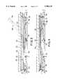
- FIG. 1is a perspective view of a trauma stretcher apparatus of the present invention
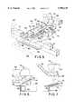
- FIG. 2is a perspective view of an x-ray tray and lifting mechanism according to one embodiment of the present invention
- FIG. 3is a sectional view taken along lines 3--3 of FIG. 1 illustrating a patient support surface and the x-ray tray and lifting mechanism with the x-ray tray in its lowered position for receiving a x-ray cassette;
- FIG. 4is a sectional view similar to the FIG. 3 illustrating the x-ray tray moved to its upwardly extended x-ray position so that the x-ray cassette is located against a bottom surface of the patient support surface;
- FIG. 5is a perspective view illustrating the lifting mechanism of FIGS. 2-4;
- FIG. 6is a partial sectional view further illustrating the lifting mechanism of FIG. 5 when the x-ray tray is in its lowered position;
- FIG. 7is a sectional view similar to FIG. 6 illustrating the lifting mechanism moving the x-ray tray toward its elevated position
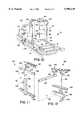
- FIG. 8is a perspective view illustrating one embodiment of a cassette holder for holding an x-ray cassette against a head section of the patient support surface when the head section is in its upwardly pivoted position;
- FIG. 9is a partial sectional view illustrating further details of the x-ray cassette holder of FIG. 8;
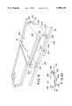
- FIG. 10is a perspective view illustrating x-ray cassette holders configured to be mounted either to a side of the bed frame adjacent the patient support surface or to the head section of the bed to support x-ray cassettes;
- FIG. 11is a perspective view illustrating details of the head section x-ray cassette holder of FIG. 10;
- FIG. 12is a perspective view illustrating further details of the side frame x-ray cassette holder of FIG. 10;
- FIG. 13is a perspective view illustrating another embodiment of an x-ray cassette holder for holding an x-ray cassette adjacent the bottom of the head section of the patient support surface when the head section is in the upwardly pivoted position;
- FIG. 14is a partial sectional view illustrating further details of the cassette holder of FIG. 13;
- FIG. 15is a partial perspective view, with portions broken away, illustrating details of a second embodiment of a lifting mechanism for moving the x-ray tray from its lowered cassette loading position to its elevated x-ray position;
- FIG. 16is a sectional view of the lifting mechanism of FIG. 15 illustrating movement of the lifting mechanism to lift the x-ray tray from its lowered position to an intermediate position;
- FIG. 17is a sectional view similar to FIG. 16 illustrating further movement of the lifting mechanism to raise the x-ray tray to its elevated position so that the x-ray cassette is located against a bottom of the patient support surface;
- FIG. 18is a sectional view of another lifting mechanism according to the present invention.
- FIG. 19is a perspective view illustrating a further embodiment of the lifting mechanism which includes a movable tray mounted below the deck of the bed which can slide relative to the deck to position an x-ray cassette at a desired location beneath a patient support deck;
- FIG. 20is a side elevation view of the lifting mechanism of FIG. 19.
- FIG. 21is an exploded perspective view of another embodiment of an x-ray cassette holder of the present invention.
- FIG. 1illustrates a stretcher apparatus 10 of the present invention.
- the stretcher 10includes a base 12 having casters 14 and a frame 16 coupled to the base 12 by front and rear lifting mechanisms 18.
- a pair of side rails 20are located on opposite sides of a patient support surface 22.
- Push handles 24are located adjacent a head end of stretcher 10.
- stretcher 10is illustrated in connection with the present invention, it is understood that any type of bed or patient support surface may be used in accordance with the present invention. In other words, the features of the present invention are not limited to use with a stretcher.
- the patient support surface 22 of the present inventionincludes a mattress 24 which may be any type of mattress structure.
- a support deck 26is spaced apart from frame 16 by standoffs 28 to provide a space 30 for receiving an x-ray cassette 32 as best illustrated in FIGS. 3 and 4.
- the x-ray cassette 32can be loaded at any desired position beneath the patient support surface 22.
- the x-ray cassette 32rests on an x-ray tray 34 movable between a lowered cassette loading position illustrated in FIG. 3 and an elevated x-ray position to move the cassette 32 into engagement with a bottom of patient support deck 26.
- a pair of lifting mechanisms 36each include a handle actuator 38 on opposite sides of the stretcher 10.
- X-ray tray 34rests on a parallelogram linkage 40 which moves the x-ray tray 34 from its lowered position illustrated in FIG. 3 to its elevated position illustrated in FIG. 4.
- X-ray tray 34includes opposite end flanges 33 and 35 located between cross bars 37 and 39 of frame 16 to maintain the tray in the same horizontal position relative to support deck 26 as the x-ray tray 34 moves up and down.
- images on the x-ray cassette 32are clearer.
- the x-ray tray 34is centered on the stretcher 10 and extends substantially the entire length and width of patient support surface 22.
- Top surface 40 of x-ray tray 34is covered with a non-slip pad having texture to prevent sliding of the x-ray cassette 32 when the stretcher is in a Trendelenburg or reverse Trendelenburg position.
- Parallelogram linkage 40includes upper horizontal members 42, lower horizontal members 44, and end connectors 46 and 48. Upper members 42 slide relative to tray 34 as shown in FIGS. 3 and 4.
- FIG. 5-7Further details of the lifting mechanism 36 of FIGS. 2-3 are illustrated in FIG. 5-7.
- Lifting mechanisms 36 located on opposite sides of the stretcher 10work in identical manners.
- Handle 38is attached to rod 52 which extends into a sleeve 54 having a slot 56.
- a pin 58is coupled to rod 52 of handle 38.
- Pin 58is coupled to spring 60 to bias the handle 38 inwardly to a storage position located below frame member 16 as illustrated in solid lines in FIG. 5.
- An outer tube 62surrounds sleeve 54.
- Outer tube 62includes a slot 64 for receiving pin 58.
- Sleeve 54includes a bearing 66 coupled to wall 68.
- a roller 70is coupled to an end of sleeve 54 by arm 72.
- a spring 74is coupled to an arm 76 which is also coupled to the distal end of sleeve 54.
- An opposite end of spring 74is coupled to a bracket 78.
- Bracket 78is coupled to
- FIGS. 6 and 7further illustrate lifting of the x-ray tray as the handle 38 is rotated.
- Spring 74pulls arm 76 to assist raising of the x-ray tray 34.
- the x-ray cassette 32can be located at any desired position beneath the patient support surface 22.
- the x-ray tray 34extends substantially beneath the entire patient support surface 22.
- the x-ray cassette 32is placed adjacent the bottom surface of the patient support deck 26. This improves the image on the x-ray cassette 32 by reducing magnification of the x-rays.
- the deck 26is illustratively made from a thick Formica, radiolucent material having the equivalent of less than one millimeter of aluminum to permit x-rays to pass through deck 26.
- a head section 90 of the patient support surface 22 and deck 26is pivotable upwardly to an elevated position as illustrated in FIGS. 3 and 8.
- a pair of pneumatic cylinders 92are coupled to head section 90.
- An actuator 94releases the pneumatic cylinders 92 to permit movement of the head section 90. Once the actuator 94 is released, cylinders 92 hold the head section 90 at the desired angle. It is desirable to be able to take x-rays of a patient when the head section 90 is in the elevated position. Therefore, another cassette holder is required to hold the x-ray cassette 32 against a bottom surface of the deck 26 of head section 90 to provide a proper x-ray image.
- FIGS. 8 and 9One embodiment of an upright cassette holder is illustrated in FIGS. 8 and 9.
- a track 100is coupled to a side frame member 102.
- a cassette holder channel 104is pivotably coupled to track 100 by a fastener 106.
- the cassette channel 104is biased upwardly in the direction of arrow 108 by a spring 110.
- a retainer 112is provided to retain the cassette holder channel 104 in its upright position adjacent and parallel to track 100 for storage. Spring 110 is not required.
- the channel 104When it is desired to load the cassette 32, the channel 104 is pivoted downwardly using handle 114. An end of cassette 32 is placed within channel 104 as best illustrated in FIG. 9. Channel 104 can then slide upwardly in the direction of arrow 116 to position the cassette 32 at a desired location adjacent patient support deck 26.
- a spring retainer arm 118is coupled to side frame member 103 by bracket 120. Spring retainer arm 118 is pivotable upwardly in the direction of arrow 122 when not in use to lie adjacent and parallel to frame member 103.
- cassette holding channel 104When not in use, cassette holding channel 104 is pivoted upwardly in the direction of arrow 108. Therefore, the retainer arm 118 and cassette holder 104 are not in an x-ray window below deck 26 of head section 90 when in the storage position.
- FIGS. 10-12Other embodiments of cassette holders are illustrated in FIGS. 10-12.
- a removable head section cassette holder 124is provided for positioning an x-ray cassette adjacent a bottom of deck 26.
- the cassette holder 124is removable from the head section 90.
- An upright cassette holder 126is also provided for attachment to side frame 16 of stretcher 10. Cassette holder 126 is useful for positioning an x-ray cassette adjacent to a patient lying on support surface 22.
- Cassette holder 124is best illustrated in FIG. 11.
- Cassette holder 124includes first, second, and third telescoping members 128, 130, and 132, respectively.
- a lower cassette holding channel 134is rigidly coupled to outer telescoping member 132.
- a top cassette holding channel 136is rigidly coupled to telescoping member 130.
- a locking member 138is rotatable to lock and release relative movement of telescoping members 130 and 132.
- Locking member 140is provided to lock and release relative movement between telescoping members 128 and 130.
- a mounting channel 142is coupled to inner telescoping member 128. The mounting channel 142 is configured to be positioned over a frame of the stretcher 10 as illustrated in FIG. 10.
- a locking member 144can be adjusted to move a threaded retention member into engagement with the frame of the stretcher 10 to hold the cassette holder 124 on the stretcher 10.
- a cassette 32is positioned between first and second channels 134 and 136 as illustrated by the dotted lines in 10 and 11.
- the distance between channels 134 and 136is adjusted by releasing locking member 138 and sliding telescoping members 130 and 134 relative to each other.
- the locking member 138is tightened.
- the position of the cassette 32 relative to the head section 90is adjusted by releasing locking member 140 to permit sliding movement of the inner telescoping member 128 relative to telescoping member 130. Therefore, the channels 134 and 136 holding cassette 32 can be moved relative to deck 26 to align the cassette 32 at the desired location. Locking member 140 is then tightened.
- Cassette holder 126is further illustrated in FIG. 12.
- Cassette holder 126includes first, second, and third telescoping members 146, 148, and 150, respectively.
- a first locking member 152is provided between telescoping members 146 and 148.
- a second locking member 154is provided between telescoping members 148 and 150.
- a mounting channel 156is coupled to telescoping member 150.
- a bottom cassette retention channel 158is rigidly coupled to center telescoping member 148.
- a support 160is coupled to inner telescoping member 148.
- Support 160is illustratively a U-shaped support.
- An arm 162is pivotably coupled to one end of support 160 by a pivot connection 164.
- a cassette support channel 166is pivotably coupled to an opposite end of arm 162 by pivot connection 168.
- arm 162 and channel 166can be pivoted outwardly to the position shown in FIG. 12 and in dotted lines in FIG. 10 to position an x-ray cassette 32 at a desired position over the patient support surface 22.
- the x-ray cassette 32can be held adjacent the patient's back using the outwardly pivoted arm and support channel 166 adjacent one end of the cassette 32.
- the other end of the cassette 32is positioned against the support surface 22.
- the cassette holder 126can also be used adjacent a side of patient support surface 22. If arm 162 and cassette channel 166 are pivoted inwardly toward support 160 as illustrated in FIG. 10, a cassette 32 may be positioned between support channels 158 and 166 adjacent the side of the support surface 22.
- Mounting channels 142 and 156are illustratively H-shaped channels. Therefore, the cassette holders 124 and 126 can each be mounted to either the head section or side section of the bed frame.
- FIGS. 13 and 14Another embodiment of cassette holder is illustrated in FIGS. 13 and 14.
- a cassette holder 170is formed as a portion of x-ray tray 134.
- X-ray tray 34is formed to include a recessed section 172.
- Cassette holder 170is pivotably coupled to the x-ray tray 34 by hinge 174. When not in use, x-ray tray 170 is pivoted downwardly in the direction of arrow 176 of FIG. 14 to the dotted storage position.
- Cassette holder 170includes a first member 178 which is coupled to hinge 174. Member 178 is formed to include a slot 180.
- An inner member 182slides within an interior region of outer member 178.
- a locking mechanism 184slides back and forth within slot 180.
- a cassette channel 186is pivotably coupled to inner member 182 and spring biased toward the back section of deck 26 in the direction of arrow 187 to hold an end of a cassette 32 against the bottom of patient support deck 26.
- An upper cassette channel 188is coupled to a top frame member 105 of stretcher 10.
- cassette holder 170is pivoted out of recess 172 to lie against the head section 90.
- Cassette 32is loaded within channel 186.
- Inner member 182is then extend upwardly in the direction of arrow 190 until a top end of cassette 32 engages top cassette channel 188.
- Locking mechanism 184is then tightened to secure the inner member 182 relative to the outer member 178. This holds the cassette 32 against a bottom of deck 26.
- cassette holder 170can be pivoted in the direction of arrow 176 to its storage position.
- FIGS. 15-17Another embodiment of the lifting mechanism of the present invention is illustrated in FIGS. 15-17. Those elements referenced by numbers identical to FIGS. 5-7 perform the same or similar function.
- handles 38 on opposite sides of the bedboth rotate toward a foot end of the stretcher 10.
- each of the rollers 70is coupled to an arm 200.
- An opposite end of arm 200is coupled to one end of spring 202.
- Another end of spring 202is coupled to a cross bar 204 extending between members 48 of the parallelogram linkage 40.
- FIGS. 15 and 17Operation of the lifting mechanism is best illustrated in FIGS. 15 and 17.
- slackexists between arms 200 and springs 202 to permit the x-ray tray to rest in its lowered loading position.
- spring 202is extended as illustrated in the dotted lines of FIG. 16.
- the roller 70 and arm 72move over center so that the spring 202 holds the x-ray tray 34 in its upwardly extended position as illustrated in FIG. 17.
- Springs 202are strong enough to hold the x-ray tray 34 and the cassette 32 against a bottom surface of deck 26.
- the lifting mechanism of FIGS. 15-17accommodates x-ray cassettes 32 having different thicknesses.
- FIG. 18Still another embodiment of a lifting mechanism 208 is illustrated in FIG. 18. Those elements referenced by numbers identical to FIGS. 5-7 perform the same or similar function.
- handles 38 on opposite sides of the bedboth rotate toward the foot end of stretcher 10.
- Handles 38are coupled to triangular-shaped linkages 210 by shafts 212.
- a spring 214connects the pair of linkages 210 to bias the handles 38 inwardly toward the center of the bed to a storage position.
- Lifting mechanism 208further includes a pair of shafts 216 coupled to linkages 210.
- First ends of springs 218are coupled to shafts 216. Washers 220 on shafts 216 are provided to retain the springs 218 on the shafts 216.
- a support member 222is rigidly coupled to frame members 42 of the parallelogram linkage. Second ends of springs 218 are coupled to the support 222 by pivot connections 224.
- linkages 210When either handle 38 is extended outwardly in the direction of arrows 225 and then rotated in the direction of arrows 226, linkages 210 also rotate in the direction of arrows 226 to stretch the spring 218 on the side of the linkage 208 of the rotated handle 38. This causes the spring 218 to pull support 222 and the frame members 42 of the parallelogram linkage in the direction of arrow 228 which causes frame members 42 to slide relative to x-ray tray 34 as discussed above. This lifts the x-ray tray 34 to its elevated position beneath the patient support deck 26.
- FIGS. 19-20A further embodiment of the lifting mechanism 230 is illustrated in FIGS. 19-20.
- the lifting mechanism 230is slidable on lower frame members 44 in the direction of arrows 232 and 234. Handles 236 are provided to facilitate movement of the lifting mechanism 230.
- the x-ray tray 238is located between side flanges 240 and 242 of cover 243 to maintain the horizontal position of x-ray tray 238 as the x-ray tray 238 is lifted upwardly in the direction of arrow 244 to the dotted position of FIG. 19.
- Lifting mechanism 230includes a handle 246 on each side of the lifting mechanism 230. When one handle 246 is rotated in the direction of arrow 248.
- a parallel linkage 250moves a support tray 252 upwardly to move the x-ray cassette 32 toward the patient support deck 26.
- FIG. 21includes two telescoping shafts 260 and 262.
- a mounting arm assembly 264includes a U-shaped bracket 266 for mounting the holder 258 to a bed frame.
- a tube portion 268slides over tube 260.
- a knob 270includes a threaded shaft 272 to lock the mounting assembly 264 in position on tube 260.
- An extension rod 274is located within tubes 260 and 262 to hold the tubes 260 and 262 together.
- Extension rod 274has an end plate 276 welded to a first end.
- a washer 278 and nut 280are coupled to an opposite threaded end 282 of extension rod 274.
- a pair of pins 284 and 286extend through tube 260 and 262, respectively.
- Pins 284 and 286are configured to engage washers 276 and 278, respectively, to hold tubes 260 and 262 together.
- a stop 288is coupled to tube section 260 by pin 290. Stop 288 holds the mounting assembly 264 on the cassette holder 258.
- a top cap 292is coupled to an end of tube 262.
- the U-shaped member 266is located on a frame of the bed. Tube sections 260 and 262 are then moved apart to load an x-ray cassette 32 between U-shaped channels 294 and 296. Top channel member 262 is then released and gravity moves the top tube 262 down over the tube 260 to retain the x-ray cassette 32 between the upper and lower channels 296 and 294.
Landscapes
- Health & Medical Sciences (AREA)
- Life Sciences & Earth Sciences (AREA)
- Medical Informatics (AREA)
- Engineering & Computer Science (AREA)
- Physics & Mathematics (AREA)
- Heart & Thoracic Surgery (AREA)
- General Health & Medical Sciences (AREA)
- Nuclear Medicine, Radiotherapy & Molecular Imaging (AREA)
- Optics & Photonics (AREA)
- Pathology (AREA)
- Radiology & Medical Imaging (AREA)
- Biomedical Technology (AREA)
- Biophysics (AREA)
- Molecular Biology (AREA)
- Surgery (AREA)
- Animal Behavior & Ethology (AREA)
- High Energy & Nuclear Physics (AREA)
- Public Health (AREA)
- Veterinary Medicine (AREA)
- General Physics & Mathematics (AREA)
- Apparatus For Radiation Diagnosis (AREA)
- Harvester Elements (AREA)
- Magnetic Treatment Devices (AREA)
- Sampling And Sample Adjustment (AREA)
- Radiography Using Non-Light Waves (AREA)
- Accommodation For Nursing Or Treatment Tables (AREA)
Abstract
Description
Claims (34)
Priority Applications (19)
| Application Number | Priority Date | Filing Date | Title |
|---|---|---|---|
| US08/895,847US5996149A (en) | 1997-07-17 | 1997-07-17 | Trauma stretcher apparatus |
| AT01203322TATE319374T1 (en) | 1997-07-17 | 1998-07-07 | HOLDER DEVICE FOR AN X-RAY CASSETTE |
| TR2000/00092TTR200000092T2 (en) | 1997-07-17 | 1998-07-07 | Trauma stretcher. |
| JP2000502705AJP2001510063A (en) | 1997-07-17 | 1998-07-07 | Stretcher for victims |
| AU85680/98AAU8568098A (en) | 1997-07-17 | 1998-07-07 | Trauma stretcher apparatus |
| BR9810906-5ABR9810906A (en) | 1997-07-17 | 1998-07-07 | Bed, carrier device for holding an x-ray cassette against a bottom surface of a back section of a bed support platform, and, x-ray cassette holder configured to be attached to a frame or to A bed |
| EP98936814AEP0996362B1 (en) | 1997-07-17 | 1998-07-07 | Trauma stretcher apparatus |
| DE69833697TDE69833697T2 (en) | 1997-07-17 | 1998-07-07 | Holder device for an X-ray cassette |
| DE0996362TDE996362T1 (en) | 1997-07-17 | 1998-07-07 | CARRYING DEVICE FOR TRAUMA PATIENTS |
| GB9927565AGB2340369B (en) | 1997-07-17 | 1998-07-07 | Trauma stretcher apparatus |
| DE69805796TDE69805796T2 (en) | 1997-07-17 | 1998-07-07 | CARRYING DEVICE FOR TRAUMA PATIENTS |
| ES98936814TES2177032T3 (en) | 1997-07-17 | 1998-07-07 | STRETCHER APPARATUS FOR PATIENTS WITH TRAUMATISM. |
| CA002295526ACA2295526A1 (en) | 1997-07-17 | 1998-07-07 | Trauma stretcher apparatus |
| PCT/US1998/013905WO1999003396A2 (en) | 1997-07-17 | 1998-07-07 | Trauma stretcher apparatus |
| AT98936814TATE218300T1 (en) | 1997-07-17 | 1998-07-07 | CARRYING DEVICE FOR TRAUMA PATIENTS |
| EP01203322AEP1163881B8 (en) | 1997-07-17 | 1998-07-07 | Holder apparatus for an X-ray cassette |
| US09/205,853US6151732A (en) | 1997-07-17 | 1998-12-04 | X-ray cassette holder for a patient support surface |
| US09/205,850US6095683A (en) | 1997-07-17 | 1998-12-04 | X-ray cassette holder apparatus |
| US09/566,428US6341398B1 (en) | 1997-07-17 | 2000-05-08 | Trauma stretcher |
Applications Claiming Priority (1)
| Application Number | Priority Date | Filing Date | Title |
|---|---|---|---|
| US08/895,847US5996149A (en) | 1997-07-17 | 1997-07-17 | Trauma stretcher apparatus |
Related Child Applications (2)
| Application Number | Title | Priority Date | Filing Date |
|---|---|---|---|
| US09/205,850DivisionUS6095683A (en) | 1997-07-17 | 1998-12-04 | X-ray cassette holder apparatus |
| US09/205,853DivisionUS6151732A (en) | 1997-07-17 | 1998-12-04 | X-ray cassette holder for a patient support surface |
Publications (1)
| Publication Number | Publication Date |
|---|---|
| US5996149Atrue US5996149A (en) | 1999-12-07 |
Family
ID=25405174
Family Applications (3)
| Application Number | Title | Priority Date | Filing Date |
|---|---|---|---|
| US08/895,847Expired - LifetimeUS5996149A (en) | 1997-07-17 | 1997-07-17 | Trauma stretcher apparatus |
| US09/205,853Expired - LifetimeUS6151732A (en) | 1997-07-17 | 1998-12-04 | X-ray cassette holder for a patient support surface |
| US09/205,850Expired - LifetimeUS6095683A (en) | 1997-07-17 | 1998-12-04 | X-ray cassette holder apparatus |
Family Applications After (2)
| Application Number | Title | Priority Date | Filing Date |
|---|---|---|---|
| US09/205,853Expired - LifetimeUS6151732A (en) | 1997-07-17 | 1998-12-04 | X-ray cassette holder for a patient support surface |
| US09/205,850Expired - LifetimeUS6095683A (en) | 1997-07-17 | 1998-12-04 | X-ray cassette holder apparatus |
Country Status (12)
| Country | Link |
|---|---|
| US (3) | US5996149A (en) |
| EP (2) | EP0996362B1 (en) |
| JP (1) | JP2001510063A (en) |
| AT (2) | ATE319374T1 (en) |
| AU (1) | AU8568098A (en) |
| BR (1) | BR9810906A (en) |
| CA (1) | CA2295526A1 (en) |
| DE (3) | DE996362T1 (en) |
| ES (1) | ES2177032T3 (en) |
| GB (1) | GB2340369B (en) |
| TR (1) | TR200000092T2 (en) |
| WO (1) | WO1999003396A2 (en) |
Cited By (37)
| Publication number | Priority date | Publication date | Assignee | Title |
|---|---|---|---|---|
| WO2000054716A2 (en) | 1999-03-16 | 2000-09-21 | Hill-Rom, Inc. | Patient support with digital x-ray cassette |
| WO2000074568A1 (en) | 1999-06-09 | 2000-12-14 | Hill-Rom Services, Inc. | A lifting apparatus for an x-ray tray in a trauma stretcher |
| US6163902A (en)* | 1999-10-22 | 2000-12-26 | Mollette; Julie M. | Trauma table top |
| US6266831B1 (en)* | 1999-04-23 | 2001-07-31 | Hill-Rom, Inc. | Storable trauma board support |
| US6286165B1 (en) | 1996-04-12 | 2001-09-11 | Hill-Rom, Inc. | Stretcher center wheel mechanism |
| US20010040939A1 (en)* | 2000-02-01 | 2001-11-15 | Masaaki Kobayashi | Radiographic apparatus |
| US6330926B1 (en)* | 1999-09-15 | 2001-12-18 | Hill-Rom Services, Inc. | Stretcher having a motorized wheel |
| GB2367745A (en)* | 2000-10-12 | 2002-04-17 | Huntleigh Technology Plc | Support surface with movable x-ray cassette trays |
| US6652140B1 (en) | 1999-03-19 | 2003-11-25 | Hill-Rom Services, Inc. | X-ray cassette holder apparatus |
| US6749034B2 (en) | 2000-05-11 | 2004-06-15 | Hill-Rom Services, Inc. | Motorized traction device for a patient support |
| US20040139545A1 (en)* | 2003-01-22 | 2004-07-22 | Reinke Christian H. | Side and end brake/steer mechanism for stretchers |
| US6834402B2 (en) | 2001-09-20 | 2004-12-28 | Hill-Rom Services, Inc. | Combination bed mover and patient transfer apparatus |
| US6862762B1 (en)* | 2002-01-11 | 2005-03-08 | Wlf, L.L.C. | Patient support apparatus |
| US6877572B2 (en) | 2000-05-11 | 2005-04-12 | Hill-Rom Services, Inc. | Motorized traction device for a patient support |
| US20060016008A1 (en)* | 2004-07-26 | 2006-01-26 | Choi Byung K | Stretcher with gear mechanism for adjustable height |
| US7018157B2 (en) | 2001-09-20 | 2006-03-28 | Hill-Rom Services, Inc. | Powered transport apparatus for a bed |
| US20060133580A1 (en)* | 2004-12-16 | 2006-06-22 | Vezina Jean A | Stretcher with dedicated multi-functional removable floating patient support platform |
| US20100050343A1 (en)* | 2008-08-29 | 2010-03-04 | Hornbach David W | Patient-support apparatus with movable top |
| US7789187B2 (en) | 2008-01-29 | 2010-09-07 | Hill-Rom Services, Inc. | Push handle with pivotable handle post |
| US20100249575A1 (en)* | 2009-03-30 | 2010-09-30 | Alexander Shvartsberg | Support component for use in imaging by magnetic resonance and x-ray |
| US20100251836A1 (en)* | 2009-04-01 | 2010-10-07 | Hunt L Trent | Apparatus and method for obtaining asphalt paving samples |
| US7810822B2 (en) | 2006-01-19 | 2010-10-12 | Hill-Rom Services, Inc. | Stretcher having hand actuated caster braking apparatus |
| US7882582B2 (en) | 2006-10-13 | 2011-02-08 | Hill-Rom Services, Inc. | User interface and control system for powered transport device of a patient support apparatus |
| US7886377B2 (en) | 2006-10-13 | 2011-02-15 | Hill-Rom Services, Inc. | Push handle with rotatable user interface |
| US7922183B2 (en) | 2006-01-19 | 2011-04-12 | Hill-Rom Services, Inc. | Stretcher having hand actuated wheel braking apparatus |
| US7953537B2 (en) | 2008-02-29 | 2011-05-31 | Hill-Rom Services, Inc. | Algorithm for power drive speed control |
| AU2005316156B2 (en)* | 2004-12-16 | 2011-08-18 | Octostop Inc. | Stretcher with dedicated multi-functional removable floating patient support platform |
| US8056162B2 (en) | 2007-04-26 | 2011-11-15 | Hill-Rom Services, Inc. | Patient support apparatus with motorized traction control |
| US8341777B2 (en) | 2003-05-21 | 2013-01-01 | Hill-Rom Services, Inc. | Hospital bed having caster braking alarm |
| US20130340170A1 (en)* | 2010-11-10 | 2013-12-26 | Robert Chinn | Life support litter having a plurality of vibration dampers |
| US8757308B2 (en) | 2009-09-10 | 2014-06-24 | Hill-Rom Services Inc. | Powered transport system and control methods |
| CN106361524A (en)* | 2016-10-08 | 2017-02-01 | 何诗跃 | Medical treatment vehicle for trauma |
| US9603764B2 (en) | 2014-02-11 | 2017-03-28 | Medline Industries, Inc. | Method and apparatus for a locking caster |
| US9707143B2 (en) | 2012-08-11 | 2017-07-18 | Hill-Rom Services, Inc. | Person support apparatus power drive system |
| US9901503B2 (en) | 2008-03-13 | 2018-02-27 | Optimedica Corporation | Mobile patient bed |
| US10080543B2 (en)* | 2014-12-01 | 2018-09-25 | General Electric Company | Integrated modular system for managing plurality of medical devices |
| US12411300B2 (en)* | 2021-09-15 | 2025-09-09 | Belden Canada Ulc | Cassette with reversible securing component and system |
Families Citing this family (14)
| Publication number | Priority date | Publication date | Assignee | Title |
|---|---|---|---|---|
| JP4508335B2 (en)* | 2000-02-01 | 2010-07-21 | キヤノン株式会社 | Radiography equipment |
| US7014159B1 (en) | 2002-10-08 | 2006-03-21 | Wade Spradley | X-ray cassette holder and clips |
| US6893156B2 (en)* | 2003-01-17 | 2005-05-17 | Steris Inc. | Pad assembly adapted for receiving an x-ray cassette and method of using the same |
| JP4068046B2 (en)* | 2003-11-20 | 2008-03-26 | 中田 隆男 | X-ray stretcher |
| ES2246133B1 (en)* | 2004-04-01 | 2007-04-01 | Suinsa Medical Systems, S.A. | TABLE FOR RADIOLOGICAL EXPLORATIONS. |
| US6969192B1 (en)* | 2004-05-12 | 2005-11-29 | Weems Hollowell | Portable X-ray cassette holder for operating rooms |
| US7694368B2 (en)* | 2006-08-04 | 2010-04-13 | Ferno-Washington, Inc. | Positive lock for height adjustable ambulance cot |
| US8038347B2 (en)* | 2007-12-21 | 2011-10-18 | General Electric Company | Portable tomographic diagnostic system with open gantry |
| CN108187246A (en)* | 2018-02-09 | 2018-06-22 | 张金庆 | A kind of department of general surgery's radiotherapy equipment |
| AU2020210222B2 (en)* | 2019-08-01 | 2025-04-03 | Modsel Pty Ltd | Patient support suitable for X-ray |
| JP6731535B2 (en)* | 2019-09-30 | 2020-07-29 | パラマウントベッド株式会社 | Sleeper device |
| JP7401401B2 (en)* | 2019-09-30 | 2023-12-19 | パラマウントベッド株式会社 | sleeper device |
| EP4099971B1 (en) | 2020-02-03 | 2025-09-17 | Alphatec Spine, Inc. | Patient positioning system |
| CN115702795A (en)* | 2021-08-05 | 2023-02-17 | 通用电气精准医疗有限责任公司 | Suspension device and X-ray imaging system |
Citations (25)
| Publication number | Priority date | Publication date | Assignee | Title |
|---|---|---|---|---|
| US1768769A (en)* | 1925-02-21 | 1930-07-01 | Kelley John Robert | X-ray photographic apparatus |
| US2989634A (en)* | 1959-07-06 | 1961-06-20 | Carlton L Ould | Radiographic film positioner |
| GB1200814A (en)* | 1968-01-19 | 1970-08-05 | Hoskins & Sewell Ltd | Improvements in patients trolleys |
| US3774045A (en)* | 1972-09-28 | 1973-11-20 | R Trott | Cart top x-ray cassette holder |
| US3795815A (en)* | 1972-10-19 | 1974-03-05 | M Weinstock | Patient retention device |
| US3904531A (en)* | 1973-11-05 | 1975-09-09 | Gen Electric | X-ray table with bucky elevator |
| US3968374A (en)* | 1974-11-22 | 1976-07-06 | Schroeder Charles H | X-ray cassette holder having lever means for positionally adjusting a cassette supporting member |
| US4193148A (en)* | 1978-08-21 | 1980-03-18 | Rush Charlie D | Transparent radiation penetrable stretcher panel |
| FR2534704A1 (en)* | 1982-10-18 | 1984-04-20 | Tuoro Maurice Di | Portable cartridge-holder device with four positions at 90 DEG to each other and with stabilised immobilising means, for emergency medical radiography at the patient's bed |
| US4464780A (en)* | 1982-08-19 | 1984-08-07 | Ruiz Gilbert G | Pediatric restraint for X-ray photography |
| US4584989A (en)* | 1984-12-20 | 1986-04-29 | Rosemarie Stith | Life support stretcher bed |
| US4651364A (en)* | 1986-05-28 | 1987-03-24 | Simmons Universal Corporation | X-ray cassette holder for a trauma stretcher |
| US4893323A (en)* | 1988-07-19 | 1990-01-09 | Cook Iii Charles F | Combination portable x-ray table and stretcher |
| US4905266A (en)* | 1988-01-29 | 1990-02-27 | Midmark Corporation | Film cartridge support for bed-like stretcher |
| US4916725A (en)* | 1988-01-29 | 1990-04-10 | Midmark Corporation | Patient support apparatus having x-ray film cartridge shuttle positioning means |
| US4926457A (en)* | 1988-01-29 | 1990-05-15 | Hill-Rom Company, Inc. | Radiolucent hospital bed surface |
| US4947418A (en)* | 1989-02-21 | 1990-08-07 | Barr Stephen J | Emergency trauma board |
| US5016268A (en)* | 1988-01-15 | 1991-05-14 | Lotman D Barry | Patient support |
| US5138646A (en)* | 1989-02-10 | 1992-08-11 | Siemens Aktiengesellschaft | X-ray diagnostics apparatus for a bedridden patient |
| US5155758A (en)* | 1990-04-19 | 1992-10-13 | Thomas Vogl | Portable device for facilitating the performance of radiographic procedures |
| US5255303A (en)* | 1992-11-17 | 1993-10-19 | Duke University | Multi-purpose emergency room trauma board |
| US5422928A (en)* | 1994-08-19 | 1995-06-06 | Payne; Cham N. | Apparatus for mounting a backboard to a gurney |
| DE4344123A1 (en)* | 1993-12-23 | 1995-06-29 | Stiegelmeyer & Co Gmbh | Hospital bed with X=ray film holder |
| US5575026A (en)* | 1994-04-19 | 1996-11-19 | Stryker Corporation | Emergency stretcher with X-frame support |
| US5703925A (en)* | 1995-08-10 | 1997-12-30 | Howard Wright Limited | X-ray cassette support apparatus |
Family Cites Families (3)
| Publication number | Priority date | Publication date | Assignee | Title |
|---|---|---|---|---|
| US4038709A (en)* | 1975-12-24 | 1977-08-02 | Kerwit Medical Products, Inc. | Dual hydraulic hospital bed |
| US4468803A (en)* | 1982-09-29 | 1984-08-28 | Ronci Mary R | X-Ray film cassette frame suspension apparatus |
| US5301221A (en)* | 1993-04-01 | 1994-04-05 | Stephen Yakubisin | Intra operative x-ray cassette holder |
- 1997
- 1997-07-17USUS08/895,847patent/US5996149A/ennot_activeExpired - Lifetime
- 1998
- 1998-07-07CACA002295526Apatent/CA2295526A1/ennot_activeAbandoned
- 1998-07-07DEDE0996362Tpatent/DE996362T1/enactivePending
- 1998-07-07ATAT01203322Tpatent/ATE319374T1/ennot_activeIP Right Cessation
- 1998-07-07TRTR2000/00092Tpatent/TR200000092T2/enunknown
- 1998-07-07EPEP98936814Apatent/EP0996362B1/ennot_activeExpired - Lifetime
- 1998-07-07EPEP01203322Apatent/EP1163881B8/ennot_activeExpired - Lifetime
- 1998-07-07ESES98936814Tpatent/ES2177032T3/ennot_activeExpired - Lifetime
- 1998-07-07WOPCT/US1998/013905patent/WO1999003396A2/enactiveIP Right Grant
- 1998-07-07JPJP2000502705Apatent/JP2001510063A/ennot_activeWithdrawn
- 1998-07-07BRBR9810906-5Apatent/BR9810906A/ennot_activeApplication Discontinuation
- 1998-07-07AUAU85680/98Apatent/AU8568098A/ennot_activeAbandoned
- 1998-07-07DEDE69805796Tpatent/DE69805796T2/ennot_activeExpired - Lifetime
- 1998-07-07DEDE69833697Tpatent/DE69833697T2/ennot_activeExpired - Lifetime
- 1998-07-07ATAT98936814Tpatent/ATE218300T1/ennot_activeIP Right Cessation
- 1998-07-07GBGB9927565Apatent/GB2340369B/ennot_activeExpired - Fee Related
- 1998-12-04USUS09/205,853patent/US6151732A/ennot_activeExpired - Lifetime
- 1998-12-04USUS09/205,850patent/US6095683A/ennot_activeExpired - Lifetime
Patent Citations (25)
| Publication number | Priority date | Publication date | Assignee | Title |
|---|---|---|---|---|
| US1768769A (en)* | 1925-02-21 | 1930-07-01 | Kelley John Robert | X-ray photographic apparatus |
| US2989634A (en)* | 1959-07-06 | 1961-06-20 | Carlton L Ould | Radiographic film positioner |
| GB1200814A (en)* | 1968-01-19 | 1970-08-05 | Hoskins & Sewell Ltd | Improvements in patients trolleys |
| US3774045A (en)* | 1972-09-28 | 1973-11-20 | R Trott | Cart top x-ray cassette holder |
| US3795815A (en)* | 1972-10-19 | 1974-03-05 | M Weinstock | Patient retention device |
| US3904531A (en)* | 1973-11-05 | 1975-09-09 | Gen Electric | X-ray table with bucky elevator |
| US3968374A (en)* | 1974-11-22 | 1976-07-06 | Schroeder Charles H | X-ray cassette holder having lever means for positionally adjusting a cassette supporting member |
| US4193148A (en)* | 1978-08-21 | 1980-03-18 | Rush Charlie D | Transparent radiation penetrable stretcher panel |
| US4464780A (en)* | 1982-08-19 | 1984-08-07 | Ruiz Gilbert G | Pediatric restraint for X-ray photography |
| FR2534704A1 (en)* | 1982-10-18 | 1984-04-20 | Tuoro Maurice Di | Portable cartridge-holder device with four positions at 90 DEG to each other and with stabilised immobilising means, for emergency medical radiography at the patient's bed |
| US4584989A (en)* | 1984-12-20 | 1986-04-29 | Rosemarie Stith | Life support stretcher bed |
| US4651364A (en)* | 1986-05-28 | 1987-03-24 | Simmons Universal Corporation | X-ray cassette holder for a trauma stretcher |
| US5016268A (en)* | 1988-01-15 | 1991-05-14 | Lotman D Barry | Patient support |
| US4905266A (en)* | 1988-01-29 | 1990-02-27 | Midmark Corporation | Film cartridge support for bed-like stretcher |
| US4916725A (en)* | 1988-01-29 | 1990-04-10 | Midmark Corporation | Patient support apparatus having x-ray film cartridge shuttle positioning means |
| US4926457A (en)* | 1988-01-29 | 1990-05-15 | Hill-Rom Company, Inc. | Radiolucent hospital bed surface |
| US4893323A (en)* | 1988-07-19 | 1990-01-09 | Cook Iii Charles F | Combination portable x-ray table and stretcher |
| US5138646A (en)* | 1989-02-10 | 1992-08-11 | Siemens Aktiengesellschaft | X-ray diagnostics apparatus for a bedridden patient |
| US4947418A (en)* | 1989-02-21 | 1990-08-07 | Barr Stephen J | Emergency trauma board |
| US5155758A (en)* | 1990-04-19 | 1992-10-13 | Thomas Vogl | Portable device for facilitating the performance of radiographic procedures |
| US5255303A (en)* | 1992-11-17 | 1993-10-19 | Duke University | Multi-purpose emergency room trauma board |
| DE4344123A1 (en)* | 1993-12-23 | 1995-06-29 | Stiegelmeyer & Co Gmbh | Hospital bed with X=ray film holder |
| US5575026A (en)* | 1994-04-19 | 1996-11-19 | Stryker Corporation | Emergency stretcher with X-frame support |
| US5422928A (en)* | 1994-08-19 | 1995-06-06 | Payne; Cham N. | Apparatus for mounting a backboard to a gurney |
| US5703925A (en)* | 1995-08-10 | 1997-12-30 | Howard Wright Limited | X-ray cassette support apparatus |
Non-Patent Citations (30)
| Title |
|---|
| "530 ED/Trauma Stretcher", Midmark Corporation brochure, six pages, 1989. |
| "921 InstaCare Trauma/Emergency Stretcher Modifications", Stryker Medical brochure, two pages, date unknown. |
| "Advantage Series Trauma Stretcher Model 1002", Stryker Patient Handling brochure, three pages, Sep., 1993. |
| "Beta One X-Ray Bed", Beta Medical Products, Inc. brochure, two pages, date unknown. |
| "Colson Trauma Stretcher", Colson brochure, one page, date unknown. |
| "Dual Control Critical Care Bed Model 2020", Stryker Medical brochure, two pages, date unknown. |
| "ED II Emergency Department Stretcher", Stryker Medical Division product brochure, two pages, date unknown. |
| "Full Length X-Ray Trauma Stretcher Model 1020 Renaissance Series", Stryker Medical brochure, two pages, May, 1995. |
| "Hausted Specialty Stretchers, The Unicare Series", Hausted product brochure, two pages,date unknown. |
| "Here are just a few of the ways a C-100 cassette holder from Monee X-Ray Works can help you!", Monee X-Ray Works brochure, four pages, date unknown. |
| "InstaCare/Emergency Stretcher Model 1000E", Stryker Medical brochure, two pages, date unknown. |
| "Patient Handling Systems", Stryker Medical Division brochure, two pages, date unknown. |
| "The Gemini Series", Hausted brochure, two pages, date unknown. |
| "The Midmark 550/555 Stretcher", Midmark Corporation brochure, four pages, 1995. |
| "X-ray Trauma Stretcher", Beta Medical Products, Inc. brochure, two pages, date unknown. |
| 530 ED/Trauma Stretcher , Midmark Corporation brochure, six pages, 1989.* |
| 921 InstaCare Trauma/Emergency Stretcher Modifications , Stryker Medical brochure, two pages, date unknown.* |
| Advantage Series Trauma Stretcher Model 1002 , Stryker Patient Handling brochure, three pages, Sep., 1993.* |
| Beta One X Ray Bed , Beta Medical Products, Inc. brochure, two pages, date unknown.* |
| Colson Trauma Stretcher , Colson brochure, one page, date unknown.* |
| Dual Control Critical Care Bed Model 2020 , Stryker Medical brochure, two pages, date unknown.* |
| ED II Emergency Department Stretcher , Stryker Medical Division product brochure, two pages, date unknown.* |
| Full Length X Ray Trauma Stretcher Model 1020 Renaissance Series , Stryker Medical brochure, two pages, May, 1995.* |
| Hausted Specialty Stretchers, The Unicare Series , Hausted product brochure, two pages,date unknown.* |
| Here are just a few of the ways a C 100 cassette holder from Monee X Ray Works can help you , Monee X Ray Works brochure, four pages, date unknown.* |
| InstaCare/Emergency Stretcher Model 1000E , Stryker Medical brochure, two pages, date unknown.* |
| Patient Handling Systems , Stryker Medical Division brochure, two pages, date unknown.* |
| The Gemini Series , Hausted brochure, two pages, date unknown.* |
| The Midmark 550/555 Stretcher , Midmark Corporation brochure, four pages, 1995.* |
| X ray Trauma Stretcher , Beta Medical Products, Inc. brochure, two pages, date unknown.* |
Cited By (80)
| Publication number | Priority date | Publication date | Assignee | Title |
|---|---|---|---|---|
| US6286165B1 (en) | 1996-04-12 | 2001-09-11 | Hill-Rom, Inc. | Stretcher center wheel mechanism |
| US6772460B2 (en) | 1996-04-12 | 2004-08-10 | Hill-Rom Services, Inc. | Pedal arrangement for stretcher apparatus |
| US6505359B2 (en) | 1996-04-12 | 2003-01-14 | Hill-Rom Services, Inc. | Stretcher center wheel mechanism |
| US6341398B1 (en)* | 1997-07-17 | 2002-01-29 | Hill-Rom Services, Inc. | Trauma stretcher |
| US6398409B1 (en)* | 1999-03-16 | 2002-06-04 | Hill-Rom Services, Inc. | Patient support with digital X-ray cassette |
| WO2000054716A2 (en) | 1999-03-16 | 2000-09-21 | Hill-Rom, Inc. | Patient support with digital x-ray cassette |
| US6652140B1 (en) | 1999-03-19 | 2003-11-25 | Hill-Rom Services, Inc. | X-ray cassette holder apparatus |
| US6266831B1 (en)* | 1999-04-23 | 2001-07-31 | Hill-Rom, Inc. | Storable trauma board support |
| WO2000074568A1 (en) | 1999-06-09 | 2000-12-14 | Hill-Rom Services, Inc. | A lifting apparatus for an x-ray tray in a trauma stretcher |
| US8397846B2 (en) | 1999-09-15 | 2013-03-19 | Hill-Rom Services, Inc. | Patient support apparatus with powered wheel |
| US7530412B2 (en)* | 1999-09-15 | 2009-05-12 | Hill-Rom Services, Inc. | Method of making and using a patient support apparatus having a motorized drive assembly |
| US20080035396A1 (en)* | 1999-09-15 | 2008-02-14 | Heimbrock Richard H | Method of making and using a patient support apparatus having a motorized drive assembly |
| US6588523B2 (en) | 1999-09-15 | 2003-07-08 | Hill-Rom Services, Inc. | Stretcher having a motorized wheel |
| US6330926B1 (en)* | 1999-09-15 | 2001-12-18 | Hill-Rom Services, Inc. | Stretcher having a motorized wheel |
| US7011172B2 (en) | 1999-09-15 | 2006-03-14 | Hill-Rom Services | Patient support apparatus having a motorized wheel |
| US20050072610A1 (en)* | 1999-09-15 | 2005-04-07 | Heimbrock Richard H. | Patient support apparatus having a motorized wheel |
| US6902019B2 (en) | 1999-09-15 | 2005-06-07 | Hill-Rom Services, Inc. | Stretcher having a motorized wheel |
| US8240410B2 (en) | 1999-09-15 | 2012-08-14 | Hill-Rom Services, Inc. | Patient support apparatus with powered wheel |
| US6163902A (en)* | 1999-10-22 | 2000-12-26 | Mollette; Julie M. | Trauma table top |
| US6928145B2 (en)* | 2000-02-01 | 2005-08-09 | Canon Kabushiki Kaisha | Radiographic apparatus |
| US20010040939A1 (en)* | 2000-02-01 | 2001-11-15 | Masaaki Kobayashi | Radiographic apparatus |
| US8267206B2 (en) | 2000-05-11 | 2012-09-18 | Hill-Rom Services, Inc. | Motorized traction device for a patient support |
| US7014000B2 (en) | 2000-05-11 | 2006-03-21 | Hill-Rom Services, Inc. | Braking apparatus for a patient support |
| US7273115B2 (en) | 2000-05-11 | 2007-09-25 | Hill-Rom Services, Inc. | Control apparatus for a patient support |
| US7195253B2 (en) | 2000-05-11 | 2007-03-27 | Hill Rom Services, Inc | Motorized traction device for a patient support |
| US8051931B2 (en) | 2000-05-11 | 2011-11-08 | Hill-Rom Services, Inc. | Motorized traction device for a patient support |
| US7828092B2 (en) | 2000-05-11 | 2010-11-09 | Hill-Rom Services, Inc. | Motorized traction device for a patient support |
| US6749034B2 (en) | 2000-05-11 | 2004-06-15 | Hill-Rom Services, Inc. | Motorized traction device for a patient support |
| US6877572B2 (en) | 2000-05-11 | 2005-04-12 | Hill-Rom Services, Inc. | Motorized traction device for a patient support |
| US7090041B2 (en) | 2000-05-11 | 2006-08-15 | Hill-Rom Services, Inc. | Motorized traction device for a patient support |
| US7407024B2 (en) | 2000-05-11 | 2008-08-05 | Hill-Rom Services, Inc. | Motorized traction device for a patient support |
| US7083012B2 (en) | 2000-05-11 | 2006-08-01 | Hill-Rom Service, Inc. | Motorized traction device for a patient support |
| GB2367745A (en)* | 2000-10-12 | 2002-04-17 | Huntleigh Technology Plc | Support surface with movable x-ray cassette trays |
| GB2367745B (en)* | 2000-10-12 | 2002-12-31 | Huntleigh Technology Plc | Patient support apparatus |
| US6811311B2 (en) | 2000-10-12 | 2004-11-02 | Huntleigh Technology Plc | Patient support including x-ray cassette support with position indicator |
| US6834402B2 (en) | 2001-09-20 | 2004-12-28 | Hill-Rom Services, Inc. | Combination bed mover and patient transfer apparatus |
| US7018157B2 (en) | 2001-09-20 | 2006-03-28 | Hill-Rom Services, Inc. | Powered transport apparatus for a bed |
| US6862762B1 (en)* | 2002-01-11 | 2005-03-08 | Wlf, L.L.C. | Patient support apparatus |
| EP2283799A2 (en) | 2003-01-22 | 2011-02-16 | Hill-Rom Services, Inc. | Side and end brake/steer mechanism for stretchers |
| WO2004064699A1 (en) | 2003-01-22 | 2004-08-05 | Hill-Rom Services, Inc. | Side and end brake/steer mechanism for stretchers |
| US7346942B2 (en) | 2003-01-22 | 2008-03-25 | Hill-Rom Services, Inc. | Brake/steer mechanism for patient support apparatus |
| US20040139545A1 (en)* | 2003-01-22 | 2004-07-22 | Reinke Christian H. | Side and end brake/steer mechanism for stretchers |
| US7480948B2 (en) | 2003-01-22 | 2009-01-27 | Hill-Rom Services , Inc. | Patient support apparatus having a brake/steer mechanism with a foot pedal gear reducer |
| US7302717B2 (en) | 2003-01-22 | 2007-12-04 | Hill-Rom Services, Inc. | Side and end brake/steer mechanism for stretchers |
| US20070271700A1 (en)* | 2003-01-22 | 2007-11-29 | Reinke Christian H | Patient Support Apparatus Having A Brake/Steer Mechanism With A Foot Pedal Gear Reducer |
| US20060137092A1 (en)* | 2003-01-22 | 2006-06-29 | Reinke Christian H | Brake/steer mechanism for patient support apparatus |
| US8341777B2 (en) | 2003-05-21 | 2013-01-01 | Hill-Rom Services, Inc. | Hospital bed having caster braking alarm |
| US7003829B2 (en) | 2004-07-26 | 2006-02-28 | Byung Ki Choi | Stretcher with gear mechanism for adjustable height |
| US20060016008A1 (en)* | 2004-07-26 | 2006-01-26 | Choi Byung K | Stretcher with gear mechanism for adjustable height |
| US7131769B2 (en)* | 2004-12-16 | 2006-11-07 | Octostop Inc. | Stretcher with dedicated multi-functional removable floating patient support platform |
| AU2005316156B2 (en)* | 2004-12-16 | 2011-08-18 | Octostop Inc. | Stretcher with dedicated multi-functional removable floating patient support platform |
| US20060133580A1 (en)* | 2004-12-16 | 2006-06-22 | Vezina Jean A | Stretcher with dedicated multi-functional removable floating patient support platform |
| US8016301B2 (en) | 2006-01-19 | 2011-09-13 | Hill-Rom Services, Inc. | Stretcher foot pedal arrangement |
| US7810822B2 (en) | 2006-01-19 | 2010-10-12 | Hill-Rom Services, Inc. | Stretcher having hand actuated caster braking apparatus |
| US7922183B2 (en) | 2006-01-19 | 2011-04-12 | Hill-Rom Services, Inc. | Stretcher having hand actuated wheel braking apparatus |
| US7886377B2 (en) | 2006-10-13 | 2011-02-15 | Hill-Rom Services, Inc. | Push handle with rotatable user interface |
| US7882582B2 (en) | 2006-10-13 | 2011-02-08 | Hill-Rom Services, Inc. | User interface and control system for powered transport device of a patient support apparatus |
| US8474073B2 (en) | 2006-10-13 | 2013-07-02 | Hill-Rom Services, Inc. | User interface for power drive system of a patient support apparatus |
| US8756726B2 (en) | 2006-10-13 | 2014-06-24 | Hill-Rom Services, Inc. | User interface for power drive system of a patient support apparatus |
| US8056162B2 (en) | 2007-04-26 | 2011-11-15 | Hill-Rom Services, Inc. | Patient support apparatus with motorized traction control |
| US7789187B2 (en) | 2008-01-29 | 2010-09-07 | Hill-Rom Services, Inc. | Push handle with pivotable handle post |
| US7953537B2 (en) | 2008-02-29 | 2011-05-31 | Hill-Rom Services, Inc. | Algorithm for power drive speed control |
| US8260517B2 (en) | 2008-02-29 | 2012-09-04 | Hill-Rom Services, Inc. | Patient support apparatus with drive wheel speed control |
| US9901503B2 (en) | 2008-03-13 | 2018-02-27 | Optimedica Corporation | Mobile patient bed |
| US10426685B2 (en) | 2008-03-13 | 2019-10-01 | Optimedica Corporation | Mobile patient bed |
| US8176584B2 (en) | 2008-08-29 | 2012-05-15 | Hill-Rom Services, Inc. | Patient-support apparatus with movable top |
| US20100050343A1 (en)* | 2008-08-29 | 2010-03-04 | Hornbach David W | Patient-support apparatus with movable top |
| US8245335B2 (en)* | 2009-03-30 | 2012-08-21 | Imns Inc. | Support component for use in imaging by magnetic resonance and x-ray |
| US20100249575A1 (en)* | 2009-03-30 | 2010-09-30 | Alexander Shvartsberg | Support component for use in imaging by magnetic resonance and x-ray |
| US20100251836A1 (en)* | 2009-04-01 | 2010-10-07 | Hunt L Trent | Apparatus and method for obtaining asphalt paving samples |
| US8757308B2 (en) | 2009-09-10 | 2014-06-24 | Hill-Rom Services Inc. | Powered transport system and control methods |
| US9205007B2 (en)* | 2010-11-10 | 2015-12-08 | Ferno-Washington, Inc. | Life support litter having a plurality of vibration dampers |
| US20130340170A1 (en)* | 2010-11-10 | 2013-12-26 | Robert Chinn | Life support litter having a plurality of vibration dampers |
| US9707143B2 (en) | 2012-08-11 | 2017-07-18 | Hill-Rom Services, Inc. | Person support apparatus power drive system |
| US10588803B2 (en) | 2012-08-11 | 2020-03-17 | Hill-Rom Services, Inc. | Person support apparatus power drive system |
| US9603764B2 (en) | 2014-02-11 | 2017-03-28 | Medline Industries, Inc. | Method and apparatus for a locking caster |
| US9993378B2 (en) | 2014-02-11 | 2018-06-12 | Medline Industries, Inc. | Method and apparatus for a locking caster |
| US10080543B2 (en)* | 2014-12-01 | 2018-09-25 | General Electric Company | Integrated modular system for managing plurality of medical devices |
| CN106361524A (en)* | 2016-10-08 | 2017-02-01 | 何诗跃 | Medical treatment vehicle for trauma |
| US12411300B2 (en)* | 2021-09-15 | 2025-09-09 | Belden Canada Ulc | Cassette with reversible securing component and system |
Also Published As
| Publication number | Publication date |
|---|---|
| GB9927565D0 (en) | 2000-01-19 |
| BR9810906A (en) | 2000-08-01 |
| EP0996362A2 (en) | 2000-05-03 |
| US6151732A (en) | 2000-11-28 |
| EP1163881B1 (en) | 2006-03-08 |
| GB2340369A (en) | 2000-02-16 |
| EP1163881B8 (en) | 2006-06-28 |
| EP0996362B1 (en) | 2002-06-05 |
| GB2340369B (en) | 2000-05-03 |
| JP2001510063A (en) | 2001-07-31 |
| US6095683A (en) | 2000-08-01 |
| ES2177032T3 (en) | 2002-12-01 |
| CA2295526A1 (en) | 1999-01-28 |
| ATE218300T1 (en) | 2002-06-15 |
| EP1163881A1 (en) | 2001-12-19 |
| DE69833697T2 (en) | 2006-08-17 |
| WO1999003396A3 (en) | 1999-04-08 |
| AU8568098A (en) | 1999-02-10 |
| DE69833697D1 (en) | 2006-05-04 |
| DE69805796D1 (en) | 2002-07-11 |
| DE996362T1 (en) | 2000-10-05 |
| DE69805796T2 (en) | 2002-11-21 |
| TR200000092T2 (en) | 2000-05-22 |
| WO1999003396A2 (en) | 1999-01-28 |
| ATE319374T1 (en) | 2006-03-15 |
Similar Documents
| Publication | Publication Date | Title |
|---|---|---|
| US5996149A (en) | Trauma stretcher apparatus | |
| US8099807B2 (en) | Storable foot section for a bed | |
| JP4806152B2 (en) | Imaging stretcher | |
| US8069513B2 (en) | Patient support apparatus having auto contour | |
| EP2158890B1 (en) | Patient-support apparatus with movable top | |
| US7131769B2 (en) | Stretcher with dedicated multi-functional removable floating patient support platform | |
| US3818516A (en) | Mobile hospital bed to facilitate x-ray examinations | |
| US4651364A (en) | X-ray cassette holder for a trauma stretcher | |
| EP1185201B1 (en) | A lifting apparatus for an x-ray tray in a trauma stretcher | |
| AU2005316156B2 (en) | Stretcher with dedicated multi-functional removable floating patient support platform |
Legal Events
| Date | Code | Title | Description |
|---|---|---|---|
| AS | Assignment | Owner name:HILL-ROM, INC., INDIANA Free format text:ASSIGNMENT OF ASSIGNORS INTEREST;ASSIGNORS:HEIMBROCK, RICHARD H.;HOWELL, CHARLES A.;REEL/FRAME:008705/0586 Effective date:19970716 | |
| STCF | Information on status: patent grant | Free format text:PATENTED CASE | |
| AS | Assignment | Owner name:HILL-ROM SERVICES, INC., INDIANA Free format text:ASSIGNMENT OF ASSIGNORS INTEREST;ASSIGNOR:HILL-ROM, INC.;REEL/FRAME:011796/0440 Effective date:20010215 | |
| FEPP | Fee payment procedure | Free format text:PAYOR NUMBER ASSIGNED (ORIGINAL EVENT CODE: ASPN); ENTITY STATUS OF PATENT OWNER: LARGE ENTITY | |
| FPAY | Fee payment | Year of fee payment:4 | |
| FPAY | Fee payment | Year of fee payment:8 | |
| FPAY | Fee payment | Year of fee payment:12 | |
| AS | Assignment | Owner name:JPMORGAN CHASE BANK, N.A., AS COLLATERAL AGENT, ILLINOIS Free format text:SECURITY INTEREST;ASSIGNORS:ALLEN MEDICAL SYSTEMS, INC.;HILL-ROM SERVICES, INC.;ASPEN SURGICAL PRODUCTS, INC.;AND OTHERS;REEL/FRAME:036582/0123 Effective date:20150908 Owner name:JPMORGAN CHASE BANK, N.A., AS COLLATERAL AGENT, IL Free format text:SECURITY INTEREST;ASSIGNORS:ALLEN MEDICAL SYSTEMS, INC.;HILL-ROM SERVICES, INC.;ASPEN SURGICAL PRODUCTS, INC.;AND OTHERS;REEL/FRAME:036582/0123 Effective date:20150908 | |
| AS | Assignment | Owner name:JPMORGAN CHASE BANK, N.A., AS COLLATERAL AGENT, ILLINOIS Free format text:SECURITY AGREEMENT;ASSIGNORS:HILL-ROM SERVICES, INC.;ASPEN SURGICAL PRODUCTS, INC.;ALLEN MEDICAL SYSTEMS, INC.;AND OTHERS;REEL/FRAME:040145/0445 Effective date:20160921 Owner name:JPMORGAN CHASE BANK, N.A., AS COLLATERAL AGENT, IL Free format text:SECURITY AGREEMENT;ASSIGNORS:HILL-ROM SERVICES, INC.;ASPEN SURGICAL PRODUCTS, INC.;ALLEN MEDICAL SYSTEMS, INC.;AND OTHERS;REEL/FRAME:040145/0445 Effective date:20160921 | |
| AS | Assignment | Owner name:ALLEN MEDICAL SYSTEMS, INC., ILLINOIS Free format text:RELEASE BY SECURED PARTY;ASSIGNOR:JPMORGAN CHASE BANK, N.A.;REEL/FRAME:050254/0513 Effective date:20190830 Owner name:HILL-ROM COMPANY, INC., ILLINOIS Free format text:RELEASE BY SECURED PARTY;ASSIGNOR:JPMORGAN CHASE BANK, N.A.;REEL/FRAME:050254/0513 Effective date:20190830 Owner name:WELCH ALLYN, INC., NEW YORK Free format text:RELEASE BY SECURED PARTY;ASSIGNOR:JPMORGAN CHASE BANK, N.A.;REEL/FRAME:050254/0513 Effective date:20190830 Owner name:MORTARA INSTRUMENT, INC., WISCONSIN Free format text:RELEASE BY SECURED PARTY;ASSIGNOR:JPMORGAN CHASE BANK, N.A.;REEL/FRAME:050254/0513 Effective date:20190830 Owner name:ANODYNE MEDICAL DEVICE, INC., FLORIDA Free format text:RELEASE BY SECURED PARTY;ASSIGNOR:JPMORGAN CHASE BANK, N.A.;REEL/FRAME:050254/0513 Effective date:20190830 Owner name:HILL-ROM SERVICES, INC., ILLINOIS Free format text:RELEASE BY SECURED PARTY;ASSIGNOR:JPMORGAN CHASE BANK, N.A.;REEL/FRAME:050254/0513 Effective date:20190830 Owner name:VOALTE, INC., FLORIDA Free format text:RELEASE BY SECURED PARTY;ASSIGNOR:JPMORGAN CHASE BANK, N.A.;REEL/FRAME:050254/0513 Effective date:20190830 Owner name:MORTARA INSTRUMENT SERVICES, INC., WISCONSIN Free format text:RELEASE BY SECURED PARTY;ASSIGNOR:JPMORGAN CHASE BANK, N.A.;REEL/FRAME:050254/0513 Effective date:20190830 Owner name:HILL-ROM, INC., ILLINOIS Free format text:RELEASE BY SECURED PARTY;ASSIGNOR:JPMORGAN CHASE BANK, N.A.;REEL/FRAME:050254/0513 Effective date:20190830 |