US5996023A - Efficient pre-alarm buffer management in intelligent video information management system - Google Patents
Efficient pre-alarm buffer management in intelligent video information management systemDownload PDFInfo
- Publication number
- US5996023A US5996023AUS09/069,257US6925798AUS5996023AUS 5996023 AUS5996023 AUS 5996023AUS 6925798 AUS6925798 AUS 6925798AUS 5996023 AUS5996023 AUS 5996023A
- Authority
- US
- United States
- Prior art keywords
- video
- video data
- alarm
- data signals
- buffer
- Prior art date
- Legal status (The legal status is an assumption and is not a legal conclusion. Google has not performed a legal analysis and makes no representation as to the accuracy of the status listed.)
- Expired - Lifetime
Links
Images


Classifications
- H—ELECTRICITY
- H04—ELECTRIC COMMUNICATION TECHNIQUE
- H04N—PICTORIAL COMMUNICATION, e.g. TELEVISION
- H04N9/00—Details of colour television systems
- H04N9/79—Processing of colour television signals in connection with recording
- H04N9/80—Transformation of the television signal for recording, e.g. modulation, frequency changing; Inverse transformation for playback
- H04N9/82—Transformation of the television signal for recording, e.g. modulation, frequency changing; Inverse transformation for playback the individual colour picture signal components being recorded simultaneously only
- H04N9/8205—Transformation of the television signal for recording, e.g. modulation, frequency changing; Inverse transformation for playback the individual colour picture signal components being recorded simultaneously only involving the multiplexing of an additional signal and the colour video signal
- H04N9/8227—Transformation of the television signal for recording, e.g. modulation, frequency changing; Inverse transformation for playback the individual colour picture signal components being recorded simultaneously only involving the multiplexing of an additional signal and the colour video signal the additional signal being at least another television signal
- G—PHYSICS
- G08—SIGNALLING
- G08B—SIGNALLING OR CALLING SYSTEMS; ORDER TELEGRAPHS; ALARM SYSTEMS
- G08B13/00—Burglar, theft or intruder alarms
- G08B13/18—Actuation by interference with heat, light, or radiation of shorter wavelength; Actuation by intruding sources of heat, light, or radiation of shorter wavelength
- G08B13/189—Actuation by interference with heat, light, or radiation of shorter wavelength; Actuation by intruding sources of heat, light, or radiation of shorter wavelength using passive radiation detection systems
- G08B13/194—Actuation by interference with heat, light, or radiation of shorter wavelength; Actuation by intruding sources of heat, light, or radiation of shorter wavelength using passive radiation detection systems using image scanning and comparing systems
- G08B13/196—Actuation by interference with heat, light, or radiation of shorter wavelength; Actuation by intruding sources of heat, light, or radiation of shorter wavelength using passive radiation detection systems using image scanning and comparing systems using television cameras
- G08B13/19602—Image analysis to detect motion of the intruder, e.g. by frame subtraction
- G—PHYSICS
- G06—COMPUTING OR CALCULATING; COUNTING
- G06F—ELECTRIC DIGITAL DATA PROCESSING
- G06F16/00—Information retrieval; Database structures therefor; File system structures therefor
- G06F16/40—Information retrieval; Database structures therefor; File system structures therefor of multimedia data, e.g. slideshows comprising image and additional audio data
- G—PHYSICS
- G08—SIGNALLING
- G08B—SIGNALLING OR CALLING SYSTEMS; ORDER TELEGRAPHS; ALARM SYSTEMS
- G08B13/00—Burglar, theft or intruder alarms
- G08B13/18—Actuation by interference with heat, light, or radiation of shorter wavelength; Actuation by intruding sources of heat, light, or radiation of shorter wavelength
- G08B13/189—Actuation by interference with heat, light, or radiation of shorter wavelength; Actuation by intruding sources of heat, light, or radiation of shorter wavelength using passive radiation detection systems
- G08B13/194—Actuation by interference with heat, light, or radiation of shorter wavelength; Actuation by intruding sources of heat, light, or radiation of shorter wavelength using passive radiation detection systems using image scanning and comparing systems
- G08B13/196—Actuation by interference with heat, light, or radiation of shorter wavelength; Actuation by intruding sources of heat, light, or radiation of shorter wavelength using passive radiation detection systems using image scanning and comparing systems using television cameras
- G08B13/19602—Image analysis to detect motion of the intruder, e.g. by frame subtraction
- G08B13/19604—Image analysis to detect motion of the intruder, e.g. by frame subtraction involving reference image or background adaptation with time to compensate for changing conditions, e.g. reference image update on detection of light level change
- G—PHYSICS
- G08—SIGNALLING
- G08B—SIGNALLING OR CALLING SYSTEMS; ORDER TELEGRAPHS; ALARM SYSTEMS
- G08B13/00—Burglar, theft or intruder alarms
- G08B13/18—Actuation by interference with heat, light, or radiation of shorter wavelength; Actuation by intruding sources of heat, light, or radiation of shorter wavelength
- G08B13/189—Actuation by interference with heat, light, or radiation of shorter wavelength; Actuation by intruding sources of heat, light, or radiation of shorter wavelength using passive radiation detection systems
- G08B13/194—Actuation by interference with heat, light, or radiation of shorter wavelength; Actuation by intruding sources of heat, light, or radiation of shorter wavelength using passive radiation detection systems using image scanning and comparing systems
- G08B13/196—Actuation by interference with heat, light, or radiation of shorter wavelength; Actuation by intruding sources of heat, light, or radiation of shorter wavelength using passive radiation detection systems using image scanning and comparing systems using television cameras
- G08B13/19634—Electrical details of the system, e.g. component blocks for carrying out specific functions
- G—PHYSICS
- G08—SIGNALLING
- G08B—SIGNALLING OR CALLING SYSTEMS; ORDER TELEGRAPHS; ALARM SYSTEMS
- G08B13/00—Burglar, theft or intruder alarms
- G08B13/18—Actuation by interference with heat, light, or radiation of shorter wavelength; Actuation by intruding sources of heat, light, or radiation of shorter wavelength
- G08B13/189—Actuation by interference with heat, light, or radiation of shorter wavelength; Actuation by intruding sources of heat, light, or radiation of shorter wavelength using passive radiation detection systems
- G08B13/194—Actuation by interference with heat, light, or radiation of shorter wavelength; Actuation by intruding sources of heat, light, or radiation of shorter wavelength using passive radiation detection systems using image scanning and comparing systems
- G08B13/196—Actuation by interference with heat, light, or radiation of shorter wavelength; Actuation by intruding sources of heat, light, or radiation of shorter wavelength using passive radiation detection systems using image scanning and comparing systems using television cameras
- G08B13/19639—Details of the system layout
- G08B13/19645—Multiple cameras, each having view on one of a plurality of scenes, e.g. multiple cameras for multi-room surveillance or for tracking an object by view hand-over
- G—PHYSICS
- G08—SIGNALLING
- G08B—SIGNALLING OR CALLING SYSTEMS; ORDER TELEGRAPHS; ALARM SYSTEMS
- G08B13/00—Burglar, theft or intruder alarms
- G08B13/18—Actuation by interference with heat, light, or radiation of shorter wavelength; Actuation by intruding sources of heat, light, or radiation of shorter wavelength
- G08B13/189—Actuation by interference with heat, light, or radiation of shorter wavelength; Actuation by intruding sources of heat, light, or radiation of shorter wavelength using passive radiation detection systems
- G08B13/194—Actuation by interference with heat, light, or radiation of shorter wavelength; Actuation by intruding sources of heat, light, or radiation of shorter wavelength using passive radiation detection systems using image scanning and comparing systems
- G08B13/196—Actuation by interference with heat, light, or radiation of shorter wavelength; Actuation by intruding sources of heat, light, or radiation of shorter wavelength using passive radiation detection systems using image scanning and comparing systems using television cameras
- G08B13/19665—Details related to the storage of video surveillance data
- G08B13/19667—Details realated to data compression, encryption or encoding, e.g. resolution modes for reducing data volume to lower transmission bandwidth or memory requirements
- G—PHYSICS
- G08—SIGNALLING
- G08B—SIGNALLING OR CALLING SYSTEMS; ORDER TELEGRAPHS; ALARM SYSTEMS
- G08B13/00—Burglar, theft or intruder alarms
- G08B13/18—Actuation by interference with heat, light, or radiation of shorter wavelength; Actuation by intruding sources of heat, light, or radiation of shorter wavelength
- G08B13/189—Actuation by interference with heat, light, or radiation of shorter wavelength; Actuation by intruding sources of heat, light, or radiation of shorter wavelength using passive radiation detection systems
- G08B13/194—Actuation by interference with heat, light, or radiation of shorter wavelength; Actuation by intruding sources of heat, light, or radiation of shorter wavelength using passive radiation detection systems using image scanning and comparing systems
- G08B13/196—Actuation by interference with heat, light, or radiation of shorter wavelength; Actuation by intruding sources of heat, light, or radiation of shorter wavelength using passive radiation detection systems using image scanning and comparing systems using television cameras
- G08B13/19665—Details related to the storage of video surveillance data
- G08B13/19671—Addition of non-video data, i.e. metadata, to video stream
- G08B13/19673—Addition of time stamp, i.e. time metadata, to video stream
- G—PHYSICS
- G08—SIGNALLING
- G08B—SIGNALLING OR CALLING SYSTEMS; ORDER TELEGRAPHS; ALARM SYSTEMS
- G08B13/00—Burglar, theft or intruder alarms
- G08B13/18—Actuation by interference with heat, light, or radiation of shorter wavelength; Actuation by intruding sources of heat, light, or radiation of shorter wavelength
- G08B13/189—Actuation by interference with heat, light, or radiation of shorter wavelength; Actuation by intruding sources of heat, light, or radiation of shorter wavelength using passive radiation detection systems
- G08B13/194—Actuation by interference with heat, light, or radiation of shorter wavelength; Actuation by intruding sources of heat, light, or radiation of shorter wavelength using passive radiation detection systems using image scanning and comparing systems
- G08B13/196—Actuation by interference with heat, light, or radiation of shorter wavelength; Actuation by intruding sources of heat, light, or radiation of shorter wavelength using passive radiation detection systems using image scanning and comparing systems using television cameras
- G08B13/19678—User interface
- G08B13/1968—Interfaces for setting up or customising the system
- G—PHYSICS
- G08—SIGNALLING
- G08B—SIGNALLING OR CALLING SYSTEMS; ORDER TELEGRAPHS; ALARM SYSTEMS
- G08B13/00—Burglar, theft or intruder alarms
- G08B13/18—Actuation by interference with heat, light, or radiation of shorter wavelength; Actuation by intruding sources of heat, light, or radiation of shorter wavelength
- G08B13/189—Actuation by interference with heat, light, or radiation of shorter wavelength; Actuation by intruding sources of heat, light, or radiation of shorter wavelength using passive radiation detection systems
- G08B13/194—Actuation by interference with heat, light, or radiation of shorter wavelength; Actuation by intruding sources of heat, light, or radiation of shorter wavelength using passive radiation detection systems using image scanning and comparing systems
- G08B13/196—Actuation by interference with heat, light, or radiation of shorter wavelength; Actuation by intruding sources of heat, light, or radiation of shorter wavelength using passive radiation detection systems using image scanning and comparing systems using television cameras
- G08B13/19678—User interface
- G08B13/19682—Graphic User Interface [GUI] presenting system data to the user, e.g. information on a screen helping a user interacting with an alarm system
- H—ELECTRICITY
- H04—ELECTRIC COMMUNICATION TECHNIQUE
- H04N—PICTORIAL COMMUNICATION, e.g. TELEVISION
- H04N5/00—Details of television systems
- H04N5/76—Television signal recording
- H—ELECTRICITY
- H04—ELECTRIC COMMUNICATION TECHNIQUE
- H04N—PICTORIAL COMMUNICATION, e.g. TELEVISION
- H04N5/00—Details of television systems
- H04N5/76—Television signal recording
- H04N5/91—Television signal processing therefor
- H04N5/92—Transformation of the television signal for recording, e.g. modulation, frequency changing; Inverse transformation for playback
- H04N5/9201—Transformation of the television signal for recording, e.g. modulation, frequency changing; Inverse transformation for playback involving the multiplexing of an additional signal and the video signal
- H04N5/9205—Transformation of the television signal for recording, e.g. modulation, frequency changing; Inverse transformation for playback involving the multiplexing of an additional signal and the video signal the additional signal being at least another television signal
- H—ELECTRICITY
- H04—ELECTRIC COMMUNICATION TECHNIQUE
- H04N—PICTORIAL COMMUNICATION, e.g. TELEVISION
- H04N7/00—Television systems
- H04N7/18—Closed-circuit television [CCTV] systems, i.e. systems in which the video signal is not broadcast
- H04N7/181—Closed-circuit television [CCTV] systems, i.e. systems in which the video signal is not broadcast for receiving images from a plurality of remote sources
- H—ELECTRICITY
- H04—ELECTRIC COMMUNICATION TECHNIQUE
- H04N—PICTORIAL COMMUNICATION, e.g. TELEVISION
- H04N5/00—Details of television systems
- H04N5/44—Receiver circuitry for the reception of television signals according to analogue transmission standards
- H04N5/445—Receiver circuitry for the reception of television signals according to analogue transmission standards for displaying additional information
- H—ELECTRICITY
- H04—ELECTRIC COMMUNICATION TECHNIQUE
- H04N—PICTORIAL COMMUNICATION, e.g. TELEVISION
- H04N5/00—Details of television systems
- H04N5/76—Television signal recording
- H04N5/78—Television signal recording using magnetic recording
- H04N5/781—Television signal recording using magnetic recording on disks or drums
- H—ELECTRICITY
- H04—ELECTRIC COMMUNICATION TECHNIQUE
- H04N—PICTORIAL COMMUNICATION, e.g. TELEVISION
- H04N5/00—Details of television systems
- H04N5/76—Television signal recording
- H04N5/78—Television signal recording using magnetic recording
- H04N5/782—Television signal recording using magnetic recording on tape
- H04N5/783—Adaptations for reproducing at a rate different from the recording rate
- H—ELECTRICITY
- H04—ELECTRIC COMMUNICATION TECHNIQUE
- H04N—PICTORIAL COMMUNICATION, e.g. TELEVISION
- H04N9/00—Details of colour television systems
- H04N9/79—Processing of colour television signals in connection with recording
- H04N9/80—Transformation of the television signal for recording, e.g. modulation, frequency changing; Inverse transformation for playback
- H04N9/804—Transformation of the television signal for recording, e.g. modulation, frequency changing; Inverse transformation for playback involving pulse code modulation of the colour picture signal components
- H04N9/8042—Transformation of the television signal for recording, e.g. modulation, frequency changing; Inverse transformation for playback involving pulse code modulation of the colour picture signal components involving data reduction
- H—ELECTRICITY
- H04—ELECTRIC COMMUNICATION TECHNIQUE
- H04N—PICTORIAL COMMUNICATION, e.g. TELEVISION
- H04N9/00—Details of colour television systems
- H04N9/79—Processing of colour television signals in connection with recording
- H04N9/80—Transformation of the television signal for recording, e.g. modulation, frequency changing; Inverse transformation for playback
- H04N9/82—Transformation of the television signal for recording, e.g. modulation, frequency changing; Inverse transformation for playback the individual colour picture signal components being recorded simultaneously only
- H04N9/8205—Transformation of the television signal for recording, e.g. modulation, frequency changing; Inverse transformation for playback the individual colour picture signal components being recorded simultaneously only involving the multiplexing of an additional signal and the colour video signal
Definitions
- the above-referenced parent patent applicationdiscloses a digital video recorder which has intelligent video information management capabilities.
- a preferred application of the recorder of the parent application, as disclosed therein,is for selective recording of video signal streams generated by closed-circuit video security surveillance cameras.
- the recorder disclosed in the parent applicationis adapted to receive simultaneous input video signal streams from up to 16 cameras.
- pre-alarm bufferingan additional strategy, referred to as pre-alarm buffering, which also promotes efficient use of limited signal storage capacity.
- the basic conceptis that the respective video streams generated by some or all of the cameras connected to the recorder are not usually selected for permanent storage. Instead, a ring buffer is provided to record the signal streams at a given (perhaps shared) field rate for a limited period of time, say one minute. If a significant event is detected, such as tripping of an alarm sensor, actuation of an alarm condition by a human operator, or detection of a predetermined characteristic of an incoming image stream by machine analysis of the image stream, then the video signal stream in the ring buffer, which would normally have been overwritten, is preserved for permanent storage.
- Pre-alarm bufferingrepresents a desirable compromise which avoids devoting permanent storage capacity to large quantities of uninteresting information, while increasing the likelihood that significant information will be permanently recorded.
- the present applicationis concerned with techniques for efficiently managing pre-alarm buffering operations.
- a video data storage apparatusincluding a plurality of video cameras, each generating a respective stream of video signals; conversion circuitry, connected to the plurality of video signals, for selectively converting the streams of video signals into respective streams of video data signals; a circular data buffer for selectively storing ones of the streams of video data signals subject to overwriting by more current video data signals; a main data store for selectively storing ones of the streams of video signals and for writing the video data signals in the main data store to a removable archive recording medium; a detection circuit for detecting an alarm condition; and a control circuit for selecting between a first process and a second process different from the first process, on the basis of the alarm condition detected by the detection circuit, the first and second processes both being processes for transferring a stream of video data signals from the circular data buffer to the main data store.
- the circular data buffer and the main data storemay respectively include first and second portions of a hard disk drive.
- the first processmay include reading the stream of video data signals to be transferred from the circular data buffer and rewriting that stream of video data signals to the main data store, and the second process may include designating the first portion of the hard disk to be a portion of the main data store.
- a method of operating a digital video recorderwhich includes a disk-shaped storage medium and which selectively records on the storage medium digital data signals representing respective streams of video signals generated by a plurality of video cameras connected to the recorder, the recorder including a pre-alarm buffer as a designated portion of the storage medium, and the method including the steps of detecting an alarm condition, selecting, on the basis of the detected alarm condition, one of two processes for designating for permanent storage video data signals stored in the pre-alarm buffer, and executing the selected one of the two processes; wherein the first of the two processes includes reading some but not all of the video data signals stored in the pre-alarm buffer and writing the read video data signals into a portion of the storage medium different from the pre-alarm buffer, and the second of the two processes includes (i) redesignating the designated portion of the storage medium corresponding to the pre-alarm buffer such that all of the video data signals stored in the designated portion are appointed for permanent storage, and (ii) designating a new portion of
- a method of operating a digital video recorderwhich includes a disk-shaped storage medium and which selectively records on the storage medium digital data signals representing respective streams of video signals generated by a plurality of video cameras connected to the recorder, the method including the steps of selecting ones of the video cameras for recording on the storage medium in a pre-alarm buffer mode; for each of the selected video cameras, designating a respective portion of the storage medium to serve as a circular buffer for temporarily storing video data signals representing video signals generated by the respective camera; temporarily storing in the designated portions video data signals representing video signals generated by the respective selected cameras; detecting an alarm condition; determining that at least one of the selected cameras is relevant to the detected alarm condition; and, for each camera determined to be relevant to the detected alarm condition: (i) re-designating for permanent storage the respective portion of the storage medium previously designated to be the circular buffer for the respective camera, and (ii) designating a portion of the storage medium, different from the redesignated portion, to serve as a circular buffer for temporarily
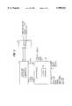
- FIG. 1is a perspective view of a video recording/personal computer (VR/PC) unit provided in accordance with the invention.
- VR/PCvideo recording/personal computer
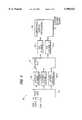
- FIG. 2is a summary block diagram representation of electronic components of the VR/PC unit of FIG. 1.
- FIG. 3is a summary block diagram representation of a front end processing/compression component shown in FIG. 2.
- FIG. 4illustrates video data and index data formats utilized by the VR/PC unit in storing video data on the hard disk provided therein.
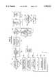
- FIG. 5illustrates processing carried on by a main processor in the VR/PC unit in response to an indication of an alarm condition.
- FIG. 6illustrates in flow-chart form a video storage processing software module, provided in accordance with the invention, for the main processor of the VR/PC unit.
- FIG. 7illustrates an alternative video data format provided, according to an aspect of the invention, for the VR/PC hard disk.
- FIG. 8is a flow-chart illustrating an alternative pre-alarm buffer management technique provided in accordance with the invention.
- FIG. 1is a perspective view of an integrated device which combines digital video recording, random access retrieval of recorded video data, and user-friendly personal-computer-based functionality.
- Reference numeral 20generally indicates the integrated device, which may be referred to as a video recording/personal computer or "VR/PC" unit.
- the VR/PC unitis adapted to receive streams of video signals generated by one or more video cameras. A preferred embodiment is configured to receive simultaneous input from 16 cameras (which are not shown in FIG. 1).
- the VR/PC unitalso provides an output video signal, either live from one or more video cameras, or reproduced from video data storage facilities provided within the VR/PC unit, to drive one or more display monitors, which also are not shown in FIG. 1.
- the internal components of the VR/PC unit 20are contained within a molded plastic housing 22.
- the internal componentsinclude control and signal processing circuitry, as well as a number of data recording devices.
- control and signal processing circuitryintegrated within the VR/PC unit there are preferably two or more fixed or "hard" data recording drives of the magnetic type, as well as at least one drive for a removable data storage medium.
- a preferred embodimentincludes both a floppy disk drive and a digital audio tape (DAT) drive.
- the floppy drivemay be used for loading software programs; the DAT drive may be used to store video data, retrieved from the internal hard drives, for permanent or archival storage on a magnetic tape formatted in accordance with the standard DAT format.
- a hinged dust-shield 24provided at a front elevation 26 of the housing 22.
- a front panel 28on which a plurality of switches are mounted. The switches permit the user to control various functions such as selecting input cameras for displaying, setting a format for a displayed video signal, and controlling playback operations.
- VR/PC unitof a type in which the present invention may be applied, is currently being sold under the trademark "INTELLEX” by the assignee of the present invention, Sensormatic Electronics Corporation, Boca Raton, Fla.
- primary componentsinclude a motherboard 40 and front end processing/compression electronics 42.
- the motherboard 40provides the overall intelligence and control for the VR/PC unit.
- the motherboard 40is constructed in accordance with conventional architecture for personal computer motherboards.
- the central processing unit for the motherboardis preferably constituted by a conventional microprocessor 44, which may, for example, be one of the models of the well known Pentium line of microprocessors.
- the motherboard 40controls, and exchanges data with, data storage devices such as the above-mentioned hard disk drives, DAT drive and floppy disk drive.
- the motherboardis also adapted to receive user control signals, which may be input via the front panel 28 (FIG. 1) or via conventional user input devices (not shown) such as a mouse and/or a keyboard.
- the motherboard 40also exchanges data with the front end processing/compression electronics 42 while receiving an input digital video signal from the front end electronics 42, and providing an output video signal to a display monitor, which is not explicitly shown in FIG. 2.
- the motherboard 40includes conventional features such as program memory, working memory, input and output data communication ports, data signal bus connections, interfaces for recording medium drives, and video interface ports. All of these are preferably of conventional construction.
- the front end electronics 42provide signal processing with respect to input video signals received via a back panel 46.
- the arrangement of the front end electronics 42may be like that incorporated in the above-mentioned INTELLEX video recorder and/or as disclosed in the above-referenced parent patent application.
- FIG. 3Certain features of the front end electronics 42 are schematically illustrated in FIG. 3.
- a multiplexer 50which selects ones of the input camera streams for recording and/or display by the VR/PC unit. Any one of the input video signal streams may be assigned to any one of three video signal locking channels 52-1, 52-2 and 52-3.
- a channel-selection multiplexer 54is arranged to assign any one of the three signal locking channels to either one of two signal conversion channels 56-1 and 56-2.
- the signal conversion channelsare provided to convert the selected stream of analog video signals into a sequence of digital video data.
- the resulting digital video datais then subjected to further processing, including data compression, as indicated at 58 in FIG. 3.
- the processed datais then made available for storage via the motherboard and/or for display.
- the digital video datais also supplied to a signal processing circuit (not separately shown in FIG. 3) which selectively applies image content analysis algorithms to one or more of the input video streams in order to detect significant characteristics of the images represented by the video streams.
- the signal processing circuitmay be programmed to detect motion, or certain types of motion, in the input video signal streams.
- FIG. 4illustrates a format in which compressed video data is stored on one or more of the hard disk drives of the VR/PC unit.
- the data stored on the hard drivesincludes compressed video data 100 and indexed data 102.
- the video datacorresponds to the incoming streams from all 16 cameras (if as many as 16 cameras are connected to the VR/PC, are in operation, and are selected for either permanent or pre-alarm buffer recording).
- the video datais preferably stored in an audio/video interleave (AVI) format.
- AVIaudio/video interleave
- the data corresponding to the streams of incoming video signalsare stored interleaved together in the form of fixed length files 104, of which N files 104 are shown in FIG. 4 as being recorded on the hard disk.
- a preferred size for each of the files 104is about 20 megabytes.
- the storage capacity provided by the files 104is limited. It is therefore a preferred mode of operating the VR/PC that the video data files be transferred to a removable storage medium, such as a magnetic tape, for archival storage.
- a removable storage mediumsuch as a magnetic tape
- the pre-alarm buffer 106preferably stores video data corresponding to the incoming video signals from all 16 cameras in an interleaved fashion and at what is substantially the full frame rate for the system (e.g., 45 fields per second divided among the 16 cameras).
- the pre-alarm buffer 106preferably stores video data corresponding to the incoming video signals from all 16 cameras in an interleaved fashion and at what is substantially the full frame rate for the system (e.g., 45 fields per second divided among the 16 cameras).
- some or all of the 16 camerasmay not be currently recorded at all in the quasi-permanent files 104, or may be stored at a "time lapse" rate that is substantially less frequent than 45/16 fields per second.
- the pre-alarm buffer 106is preferably implemented as a ring buffer on the hard disk and may, for example, store all of the video fields captured at the front end electronics over the past 60 seconds. As in the files 104, the respective signal streams are stored in an interleaved fashion in the pre-alarm buffer 106. It should also be understood that at least some of the 16 cameras may be placed in an "inactive" mode, such that not even pre-alarm buffering is performed for the signals generated from such cameras. In this case, greater storage bandwidth for each other camera is available in the pre-alarm buffer.
- index data on the hard diskoverall indexing information covering all of the files 104 is indicated at reference numeral 108.
- a starting date and time and an ending date and timeare provided for each of the N files 104.
- An additional, file-specific indexis provided with respect to each one of the individual files 104.
- This file-specific indexis illustrated at 110 and provides, for each field of video data, the date and time at which the field was captured, the camera by which the field was captured, event-related information, and the offset within the file at which the field can be found.
- the event information given for a particular fieldmay include data indicative of the occurrence of more than one type of event at the time that the field was captured.
- the detection of eventsmay be accomplished through alarm sensors interfaced to the VR/PC unit, and/or by analysis of characteristics of the image stream.
- the analysismay have occurred either at the time the image stream was received or by playing back the image stream at a later time.
- the image stream analysis algorithms used to detect the eventsmay return confidence factor values in addition to detecting that an event itself has occurred. In such cases, the data indicating that an event has been detected may be accompanied by the confidence factor provided by the event detection algorithm, as indicated at reference numeral 114.
- the indexing information 102is stored on the same hard disk with the associated video data files 100, and the indexing information is also stored on a second hard disk.
- the second hard diskmay then be accessed in order to search for the locations on the first hard disk of video data that is of interest to the user, while access to the first hard disk for the purpose of storing new video data thereon continues without interruption for index searching.
- two hard disksare provided, of which one is used for video data storage (and associated indexing) while the other hard disk is not used for video data storage, but rather is dedicated to backup or "shadow" index information and storage of programs or the like.
- three or more hard disk drivesare provided. In the latter embodiment, one of the hard drives is dedicated to the shadow index and program information storage, and the other two or more hard disks are available for video data storage.
- step 120it is assumed that an alarm message has been received by the microprocessor 44 from the front end electronics 42. It is then determined, at step 120, whether a user of the VR/PC unit has elected to have alarms handled according to a standard protocol or a custom protocol. If a standard protocol has been selected, then step 122 follows step 120. At step 122, one or more predetermined "alarm out" signals are generated according to the type of alarm message that was received.
- the "alarm out" signal or signalsmay automatically close or lock doors, actuate sirens or visible alarm indications, or the like.
- step 124at which a message is generated to cause the front end electronics 42 to change the sequence in which the video signal fields are captured from the respective cameras attached to the VR/PC unit.
- cameras expected to produce images relevant to the alarm conditionmay be added to the sequence of cameras selected for recording, or may have their share of the recording bandwidth increased.
- step 126at which it is determined whether the VR/PC unit is being operated in a pre-alarm buffering mode. If so, then step 128 follows step 126.
- step 130(which directly follows step 126 if the VR/PC is not being operated in a pre-alarm buffering mode).
- the alarm timeris set (or extended, if an alarm condition is already in effect), and the detected alarm event is added to a list of alarm events maintained by the microprocessor 44.
- Step 132follows step 130. Step 132 indicates that the recording sequence established at step 124 is maintained until the alarm timer times out. The determination as to whether the last alarm has timed out is made at step 134, and if this occurs, the alarm timer is shut down (step 136).
- step 138follows step 120.
- step 138the determination is made as to the camera, type of event and the time of occurrence relative to the alarm condition which has been detected.
- step 140at which the relevant camera, event type and time data are used to fetch the appropriate event response script from an event response script database 142.
- step 144a software loop, indicated at step 144, which is carried out for each command in the retrieved event response script. The loop is made up of steps 146, 148 and 150.
- step 146the command corresponding to the present line in the script is read.
- a message corresponding to the commandis encoded, and at step 150 the message is sent to a system director software component, which functions as a message clearing house for the software which programs the microprocessor 44. It will be understood that the command messages sent to the system director software component will trigger appropriate responses in other software components which control operation of the microprocessor 44.
- the exemplary event response script set forth aboveconsists of six lines.
- the first lineindicates that the alarm 1 output signal is to be turned on. This may be, for example, a signal to actuate a visual alarm indicator such as a flashing light.
- the second lineindicates that the alarm 2 output signal is to be turned on. This may operate, for example, an audible alarm indicator, such as a siren.
- the third lineindicates that the rate at which fields from camera 1 are to be captured for recording is set to 30 fields per second. The remaining recording bandwidth will then be allocated among other cameras which had previously been sequenced for recording.
- the fourth lineindicates that recording status for camera 1 is to be set to "on". This command would override any previous command that had software-disabled camera 1.
- the fifth commandindicates that the status defined by the first four lines of the response script is to be maintained for 30 seconds.
- the sixth and final line of the scriptindicates that the prior operating status of the system is to resume after the 30-second alarm response.
- the exemplary event response script shown abovecontains no commands in regard to video data that has been pre-alarm buffered, but it will be appreciated that the script may include commands to secure for permanent storage relevant video data in the pre-alarm buffer, as discussed above in connection with step 128.
- the above-mentioned video storage software componentperforms the functions of managing pre-alarm video data buffering on the hard disk or disks, storing incoming video streams on the hard disk, and indexing the stored video data on the hard disk.
- the video data format on the diskwas described above, in connection with FIG. 4.
- the video storage software componentis illustrated in flow-chart form on FIG. 6. Initially, it is determined at step 200 whether the video storage software component is now engaged in the pre-alarm buffer management portion of its function or the function of storing incoming video data for quasi-permanent recording (represented by block 202). For the sake of the further discussion, it will be assumed that the video storage software component is engaged in pre-alarm buffer management. In this case, it is determined, as represented at decision step 204, whether an alarm condition has been detected.
- step 206it will be recalled that the pre-alarm buffer portion of the hard disk's space was indicated by reference numeral 106 in FIG. 4; it should also be understood that a "chunk" of video data corresponds to a quantity of data that is conveniently handled and buffered in preparation for writing the data onto the hard disk).
- step 208it is determined whether the end of the ring buffer portion 106 of the hard disk has been reached (step 208). If so, the pointer indicative of the next storage location in the ring buffer 106 is moved to the front of the ring buffer (step 210). Otherwise, the pointer is simply moved to the next storage location in the ring buffer 106 (step 212).
- Step 214represents a decision point in the video storage software component, at which a selection is made between alternative processes for preventing video data stored in the pre-alarm buffer from being overwritten, and securing the data of interest for permanent storage.
- the decision as to which one of the alternative processes to employmay be made on a number of different bases, but preferably is to be made by determining what proportion of the video data stored in the pre-alarm buffer is relevant to the alarm condition that was detected. One way this may be done is by comparing the total number of camera streams stored in the pre-alarm buffer with the number of cameras indicated as "relevant" in an alarm-handling script that has been established for the detected alarm condition.
- a first processrepresented by steps 216-220 would be selected. If all or a relatively large number of the camera streams being recorded in the pre-alarm buffer are relevant to the alarm condition, then a process represented by steps 222 and 224 would be selected.
- the process for securing for permanent storage video data in the pre-alarm bufferis adapted to the currently-detected alarm condition.
- the process of securing for permanent recording video data stored in the pre-alarm buffermay be referred to as pre-alarm buffer "integration" in the sense that data from the pre-alarm buffer is being integrated with other video data selected for permanent storage.
- the pre-alarm buffer integration process of steps 216-220begins with copying from the pre-alarm buffer portion of the hard disk to the "permanent storage" portion of the hard disk the video data in the pre-alarm buffer which was generated by cameras that are relevant to the currently-detected alarm condition. That is, the relevant data is read from the pre-alarm buffer portion 106 of the hard disk (FIG. 4) and then is written into the one of the permanent storage files 104 into which interleaved video data is currently being recorded. As indicated in step 218 of FIG. 6, the copying of the relevant data from the pre-alarm buffer portion to the permanent storage portion of the hard disk continues until all of the relevant data has been transferred. Then, as indicated at step 220, the pointer data for the pre-alarm buffer is reset.
- the alternative pre-alarm buffer integration processavoids the processing burden required for reading data from the pre-alarm buffer and rewriting the data in the permanent storage portion of the hard disk. Instead, a new portion of the disk, different from that currently being used for the pre-alarm buffer, is designated to be the pre-alarm buffer and the existing pre-alarm buffer data, in its entirety, is designated for permanent storage. This can be accomplished entirely by updating pointer values and index data, so that no reading and rewriting of the video data itself is required. Although this technique is advantageous in terms of conserving processing resources, it represents a potential waste of storage capacity, to the extent that any of the data in the pre-alarm buffer is not relevant to the currently detected alarm condition.
- the pre-alarm buffer integration process of steps 216 and 218, which entails reading video data from the pre-alarm buffer and then writing that data into a permanent storage file,may also be carried out according to the following alternative.
- the occurrence of an alarminitiates reading from the pre-alarm buffer of implicated camera streams for transfer to the permanent data file; at the same time, current data for those streams continues to be written into the pre-alarm buffer.
- the reading/transferproceeds at a faster rate than the writing of the current data, and continues until the reading/transfer "catches up" to the current data. At that point, the current data is written directly into the permanent storage file, and this continues until the alarm interval ends.
- recording of the relevant camera streams into the pre-alarm bufferresumes.
- FIG. 7shows a modification to the video data format of FIG. 4, in that the pre-alarm buffer 106 is replaced with separate ring buffers 230, each of which is dedicated to a respective one of the cameras selected for pre-alarm buffering.
- provision of dedicated buffers for each camera to be pre-alarm recordedeliminates any need for reading and rewriting the pre-alarm buffered data in the event of any relevant alarm condition.
- step 236follows step 232.
- steps 238 and 240are carried out.
- the ring buffer corresponding to the relevant camerais redesignated for permanent storage and then a new ring buffer is established for the camera (step 240).
- the impact of step 238is illustrated at 242 in FIG. 7, which provides some details of a "permanent recording" video data file 104 which has been designated "file number 1".
- blocks 244-1 and 244-2represent blocks of video data which include interleaved streams generated from a plurality of cameras.
- Blocks 244-1 and 244-2represent the data format produced when a number of camera streams were designated for concurrent recording in a permanent portion of the hard disk with time-division multiplexing of the recording bandwidth.
- a non-interleaved data block 246is shown as present between blocks 244-1 and 244-2.
- Block 246corresponds to video data produced by a single camera, originally recorded in a pre-alarm ring buffer for that camera which was later re-designated for permanent storage.
- Marker 248is present in the sequence of data blocks to indicate that the next block is a non-interleaved block. It will be understood that the sequence of blocks illustrated at 242 is a virtual sequence, established by index and pointing information used to manage the data recorded on the hard disk.
Landscapes
- Engineering & Computer Science (AREA)
- Multimedia (AREA)
- General Physics & Mathematics (AREA)
- Physics & Mathematics (AREA)
- Signal Processing (AREA)
- Human Computer Interaction (AREA)
- Theoretical Computer Science (AREA)
- Library & Information Science (AREA)
- Computer Vision & Pattern Recognition (AREA)
- Data Mining & Analysis (AREA)
- General Engineering & Computer Science (AREA)
- Databases & Information Systems (AREA)
- Television Signal Processing For Recording (AREA)
- Closed-Circuit Television Systems (AREA)
- Alarm Systems (AREA)
- Signal Processing For Digital Recording And Reproducing (AREA)
- Management Or Editing Of Information On Record Carriers (AREA)
Abstract
Description
______________________________________ Event Response Script (Example) ______________________________________ ALARM1 OUT = ON (1) ALARM2 OUT = ON (2) CAMERA1RATE = 30 (3) CAMERA1 = ON (4) WAIT = 30 (5) RESUME (6) ______________________________________
Claims (9)
Priority Applications (8)
| Application Number | Priority Date | Filing Date | Title |
|---|---|---|---|
| US09/069,257US5996023A (en) | 1996-10-31 | 1998-04-29 | Efficient pre-alarm buffer management in intelligent video information management system |
| ARP990101958AAR015030A1 (en) | 1998-04-29 | 1999-04-28 | VIDEO AND METHOD DATA STORAGE DEVICE FOR OPERATION |
| EP99918899AEP1073964B1 (en) | 1998-04-29 | 1999-04-29 | Efficient pre-alarm buffer management |
| CA002325635ACA2325635C (en) | 1998-04-29 | 1999-04-29 | Efficient pre-alarm buffer management |
| PCT/US1999/009317WO1999056216A1 (en) | 1998-04-29 | 1999-04-29 | Efficient pre-alarm buffer management |
| BR9909922-5ABR9909922A (en) | 1998-04-29 | 1999-04-29 | Efficient management of pre-alarm damping |
| AU36706/99AAU755668B2 (en) | 1998-04-29 | 1999-04-29 | Efficient pre-alarm buffer management |
| JP2000546311AJP2002513224A (en) | 1998-04-29 | 1999-04-29 | Efficient pre-alarm buffer management |
Applications Claiming Priority (2)
| Application Number | Priority Date | Filing Date | Title |
|---|---|---|---|
| US08/740,627US5884042A (en) | 1996-10-31 | 1996-10-31 | Data identification in an intelligent video information management system |
| US09/069,257US5996023A (en) | 1996-10-31 | 1998-04-29 | Efficient pre-alarm buffer management in intelligent video information management system |
Related Parent Applications (1)
| Application Number | Title | Priority Date | Filing Date |
|---|---|---|---|
| US08/740,627Continuation-In-PartUS5884042A (en) | 1996-10-31 | 1996-10-31 | Data identification in an intelligent video information management system |
Publications (1)
| Publication Number | Publication Date |
|---|---|
| US5996023Atrue US5996023A (en) | 1999-11-30 |
Family
ID=22087761
Family Applications (1)
| Application Number | Title | Priority Date | Filing Date |
|---|---|---|---|
| US09/069,257Expired - LifetimeUS5996023A (en) | 1996-10-31 | 1998-04-29 | Efficient pre-alarm buffer management in intelligent video information management system |
Country Status (8)
| Country | Link |
|---|---|
| US (1) | US5996023A (en) |
| EP (1) | EP1073964B1 (en) |
| JP (1) | JP2002513224A (en) |
| AR (1) | AR015030A1 (en) |
| AU (1) | AU755668B2 (en) |
| BR (1) | BR9909922A (en) |
| CA (1) | CA2325635C (en) |
| WO (1) | WO1999056216A1 (en) |
Cited By (54)
| Publication number | Priority date | Publication date | Assignee | Title |
|---|---|---|---|---|
| US6281242B1 (en)* | 1997-07-15 | 2001-08-28 | Daiichi Pharmaceutical Co., Ltd. | Prophylactic or therapeutic agent for amnesia |
| US6317152B1 (en)* | 1999-07-17 | 2001-11-13 | Esco Electronics Corporation | Digital video recording system |
| US20030016745A1 (en)* | 2001-07-23 | 2003-01-23 | Park Goo-Man | Multi-channel image encoding apparatus and encoding method thereof |
| US20030091327A1 (en)* | 2001-11-14 | 2003-05-15 | Sanyo Electric Co., Ltd. | Monitor recording and reproducing device |
| US6570496B2 (en)* | 2000-04-04 | 2003-05-27 | Rick A. Britton | Networks and circuits for alarm system operations |
| US20030154246A1 (en)* | 2001-12-18 | 2003-08-14 | Ville Ollikainen | Server for storing files |
| WO2002073950A3 (en)* | 2001-03-14 | 2003-11-20 | Comtrak Technologies Llc | Digital video recording system |
| US20040061777A1 (en)* | 2002-05-20 | 2004-04-01 | Mokhtar Sadok | Detecting fire using cameras |
| US20040146274A1 (en)* | 2003-01-15 | 2004-07-29 | Matsushita Electric Industrial Co., Ltd. | Digital video recorder, method of driving the video recorder and program |
| US20040174440A1 (en)* | 1998-08-21 | 2004-09-09 | Sony Corporation | Information processing apparatus, information processing method, and medium |
| US20040189871A1 (en)* | 2003-03-31 | 2004-09-30 | Canon Kabushiki Kaisha | Method of generating moving picture information |
| US20040228609A1 (en)* | 2003-04-25 | 2004-11-18 | Pioneer Corporation | Recording apparatus and recording control method |
| US20040240546A1 (en)* | 2003-05-29 | 2004-12-02 | Lsi Logic Corporation | Method and/or apparatus for analyzing the content of a surveillance image |
| US20050198340A1 (en)* | 2002-04-26 | 2005-09-08 | Takatoshi Nakamura | Information providing method, information processing device, information collection system, communication method, communication system, relay device, and communication device |
| US20060167672A1 (en)* | 2004-03-31 | 2006-07-27 | Goldman Jerry Y | Method and apparatus for representing, managing and problem reporting in surveillance networks |
| US7088387B1 (en)* | 1997-08-05 | 2006-08-08 | Mitsubishi Electric Research Laboratories, Inc. | Video recording device responsive to triggering event |
| CN1303541C (en)* | 2003-08-20 | 2007-03-07 | 上海乐金广电电子有限公司 | Memory operating method and device for disc recording player |
| US20070063838A1 (en)* | 2005-09-21 | 2007-03-22 | International Business Machines Corporation | System and method for suveillance of supsects of automated banking machine fraud |
| US20080080843A1 (en)* | 2006-09-29 | 2008-04-03 | Hibbard Gary D | Systems and methods to improve consumer product reliability and lifetime of a hard disk drive by reducing its activity |
| EP1525742A4 (en)* | 2002-07-29 | 2008-05-07 | Uhs Systems Pty Ltd | A telemetry system |
| US20080147910A1 (en)* | 2006-09-29 | 2008-06-19 | Hibbard Gary D | Provisional load sharing buffer for reducing hard disk drive (hdd) activity and improving reliability and lifetime |
| US20080205852A1 (en)* | 2000-03-06 | 2008-08-28 | Seiji Oura | Encoded data recording apparatus and mobile terminal |
| US20090002491A1 (en)* | 2005-09-16 | 2009-01-01 | Haler Robert D | Vehicle-mounted video system with distributed processing |
| US20090122875A1 (en)* | 2005-03-07 | 2009-05-14 | Koninklijke Philips Electronics, N.V. | Buffering of video stream data |
| US7577199B1 (en) | 2003-06-19 | 2009-08-18 | Nvidia Corporation | Apparatus and method for performing surveillance using motion vectors |
| US20100167687A1 (en)* | 2008-10-30 | 2010-07-01 | Digital Ally, Inc. | Multi-functional remote monitoring system |
| US8004565B2 (en) | 2003-06-19 | 2011-08-23 | Nvidia Corporation | System and method for using motion vectors for object tracking |
| CN102376146A (en)* | 2010-08-20 | 2012-03-14 | 上海弘视通信技术有限公司 | Image analysis alarm signal-based method for storing information of alarm event |
| US20150110455A1 (en)* | 2013-10-23 | 2015-04-23 | Nvidia Corporation | Utility and method for capturing computer-generated video output |
| US9253452B2 (en) | 2013-08-14 | 2016-02-02 | Digital Ally, Inc. | Computer program, method, and system for managing multiple data recording devices |
| US9565462B1 (en)* | 2013-04-26 | 2017-02-07 | SportXast, LLC | System, apparatus and method for creating, storing and transmitting sensory data triggered by an event |
| US9712730B2 (en) | 2012-09-28 | 2017-07-18 | Digital Ally, Inc. | Portable video and imaging system |
| US9841259B2 (en) | 2015-05-26 | 2017-12-12 | Digital Ally, Inc. | Wirelessly conducted electronic weapon |
| US9958228B2 (en) | 2013-04-01 | 2018-05-01 | Yardarm Technologies, Inc. | Telematics sensors and camera activation in connection with firearm activity |
| US10013883B2 (en) | 2015-06-22 | 2018-07-03 | Digital Ally, Inc. | Tracking and analysis of drivers within a fleet of vehicles |
| US10075681B2 (en) | 2013-08-14 | 2018-09-11 | Digital Ally, Inc. | Dual lens camera unit |
| US10192277B2 (en) | 2015-07-14 | 2019-01-29 | Axon Enterprise, Inc. | Systems and methods for generating an audit trail for auditable devices |
| US20190104333A1 (en)* | 2016-09-26 | 2019-04-04 | Amazon Technologies, Inc. | Streaming and Storing Video for Audio/Video Recording and Communication Devices |
| US10272848B2 (en) | 2012-09-28 | 2019-04-30 | Digital Ally, Inc. | Mobile video and imaging system |
| US10390732B2 (en) | 2013-08-14 | 2019-08-27 | Digital Ally, Inc. | Breath analyzer, system, and computer program for authenticating, preserving, and presenting breath analysis data |
| US10409621B2 (en) | 2014-10-20 | 2019-09-10 | Taser International, Inc. | Systems and methods for distributed control |
| US10521675B2 (en) | 2016-09-19 | 2019-12-31 | Digital Ally, Inc. | Systems and methods of legibly capturing vehicle markings |
| CN111010521A (en)* | 2018-10-04 | 2020-04-14 | 三星电子株式会社 | Method and system for recording super slow motion video in a portable electronic device |
| US10764542B2 (en) | 2014-12-15 | 2020-09-01 | Yardarm Technologies, Inc. | Camera activation in response to firearm activity |
| US10904474B2 (en) | 2016-02-05 | 2021-01-26 | Digital Ally, Inc. | Comprehensive video collection and storage |
| US10911725B2 (en) | 2017-03-09 | 2021-02-02 | Digital Ally, Inc. | System for automatically triggering a recording |
| US10964351B2 (en) | 2013-08-14 | 2021-03-30 | Digital Ally, Inc. | Forensic video recording with presence detection |
| US11024137B2 (en) | 2018-08-08 | 2021-06-01 | Digital Ally, Inc. | Remote video triggering and tagging |
| US11151863B2 (en)* | 2019-06-04 | 2021-10-19 | Yokogawa Electric Corporation | Information processing apparatus, alarm management system, and alarm management method |
| US11237708B2 (en) | 2020-05-27 | 2022-02-01 | Bank Of America Corporation | Video previews for interactive videos using a markup language |
| US11334768B1 (en)* | 2016-07-05 | 2022-05-17 | Snap Inc. | Ephemeral content management |
| US11461535B2 (en) | 2020-05-27 | 2022-10-04 | Bank Of America Corporation | Video buffering for interactive videos using a markup language |
| US11822600B2 (en) | 2015-09-15 | 2023-11-21 | Snap Inc. | Content tagging |
| US11950017B2 (en) | 2022-05-17 | 2024-04-02 | Digital Ally, Inc. | Redundant mobile video recording |
Families Citing this family (7)
| Publication number | Priority date | Publication date | Assignee | Title |
|---|---|---|---|---|
| DE60329730D1 (en)* | 2002-03-07 | 2009-12-03 | Nokia Corp | Digital recording method |
| GB2386244A (en)* | 2002-03-07 | 2003-09-10 | Nokia Corp | Method of digital recording |
| US8928752B2 (en) | 2006-08-31 | 2015-01-06 | Stellar Llc | Recording device with pre-start signal storage capability |
| US7593034B2 (en) | 2006-08-31 | 2009-09-22 | Dekeyser Paul | Loop recording with book marking |
| EP2407943B1 (en) | 2010-07-16 | 2016-09-28 | Axis AB | Method for event initiated video capturing and a video camera for capture event initiated video |
| CN104639859B (en)* | 2013-11-08 | 2017-10-27 | 浙江大华技术股份有限公司 | A kind of video monitoring equipment and its method for carrying out data syn-chronization |
| FR3028129B1 (en)* | 2014-11-03 | 2016-12-30 | Vigipack | VIDEO SURVEILLANCE SYSTEM FOR MULTIPLE CAMERAS |
Citations (6)
| Publication number | Priority date | Publication date | Assignee | Title |
|---|---|---|---|---|
| US5724475A (en)* | 1995-05-18 | 1998-03-03 | Kirsten; Jeff P. | Compressed digital video reload and playback system |
| US5822542A (en)* | 1996-10-31 | 1998-10-13 | Sensormatic Electronics Corporation | Electronic and structural components of an intelligent video information management apparatus |
| US5825969A (en)* | 1994-02-18 | 1998-10-20 | Hitachi, Ltd. | Information management apparatus for inhibiting reproduction in a video cassette recorder |
| US5854902A (en)* | 1996-10-31 | 1998-12-29 | Sensormatic Electronics Corporation | Video data capture and formatting in intelligent video information management system |
| US5862342A (en)* | 1996-10-31 | 1999-01-19 | Sensormatic Electronics Corporation | Intelligent video information management system with information archiving capabilities |
| US5909548A (en)* | 1996-10-31 | 1999-06-01 | Sensormatic Electronics Corporation | Apparatus for alerting human operator to status conditions of intelligent video information management system |
Family Cites Families (3)
| Publication number | Priority date | Publication date | Assignee | Title |
|---|---|---|---|---|
| JP2528789B2 (en)* | 1985-06-26 | 1996-08-28 | 中央電子 株式会社 | Video information management device |
| CA2248069A1 (en) | 1995-03-06 | 1996-09-12 | Bell, Deryl L. | Computer based event capturing system having flexible storage |
| US5982418A (en)* | 1996-04-22 | 1999-11-09 | Sensormatic Electronics Corporation | Distributed video data storage in video surveillance system |
- 1998
- 1998-04-29USUS09/069,257patent/US5996023A/ennot_activeExpired - Lifetime
- 1999
- 1999-04-28ARARP990101958Apatent/AR015030A1/ennot_activeApplication Discontinuation
- 1999-04-29JPJP2000546311Apatent/JP2002513224A/ennot_activeWithdrawn
- 1999-04-29CACA002325635Apatent/CA2325635C/ennot_activeExpired - Lifetime
- 1999-04-29EPEP99918899Apatent/EP1073964B1/ennot_activeExpired - Lifetime
- 1999-04-29AUAU36706/99Apatent/AU755668B2/ennot_activeCeased
- 1999-04-29WOPCT/US1999/009317patent/WO1999056216A1/enactiveIP Right Grant
- 1999-04-29BRBR9909922-5Apatent/BR9909922A/ennot_activeIP Right Cessation
Patent Citations (6)
| Publication number | Priority date | Publication date | Assignee | Title |
|---|---|---|---|---|
| US5825969A (en)* | 1994-02-18 | 1998-10-20 | Hitachi, Ltd. | Information management apparatus for inhibiting reproduction in a video cassette recorder |
| US5724475A (en)* | 1995-05-18 | 1998-03-03 | Kirsten; Jeff P. | Compressed digital video reload and playback system |
| US5822542A (en)* | 1996-10-31 | 1998-10-13 | Sensormatic Electronics Corporation | Electronic and structural components of an intelligent video information management apparatus |
| US5854902A (en)* | 1996-10-31 | 1998-12-29 | Sensormatic Electronics Corporation | Video data capture and formatting in intelligent video information management system |
| US5862342A (en)* | 1996-10-31 | 1999-01-19 | Sensormatic Electronics Corporation | Intelligent video information management system with information archiving capabilities |
| US5909548A (en)* | 1996-10-31 | 1999-06-01 | Sensormatic Electronics Corporation | Apparatus for alerting human operator to status conditions of intelligent video information management system |
Cited By (98)
| Publication number | Priority date | Publication date | Assignee | Title |
|---|---|---|---|---|
| US6281242B1 (en)* | 1997-07-15 | 2001-08-28 | Daiichi Pharmaceutical Co., Ltd. | Prophylactic or therapeutic agent for amnesia |
| US7088387B1 (en)* | 1997-08-05 | 2006-08-08 | Mitsubishi Electric Research Laboratories, Inc. | Video recording device responsive to triggering event |
| US7391443B2 (en) | 1998-08-21 | 2008-06-24 | Sony Corporation | Information processing apparatus, information processing method, and medium |
| US20040174440A1 (en)* | 1998-08-21 | 2004-09-09 | Sony Corporation | Information processing apparatus, information processing method, and medium |
| US6317152B1 (en)* | 1999-07-17 | 2001-11-13 | Esco Electronics Corporation | Digital video recording system |
| US20010052131A1 (en)* | 1999-07-17 | 2001-12-13 | Hobson Gregory L. | Digital video recording system |
| US7116353B2 (en) | 1999-07-17 | 2006-10-03 | Esco Corporation | Digital video recording system |
| US8503864B2 (en)* | 2000-03-06 | 2013-08-06 | Fujitsu Mobile Communications Limited | Encoded data recording apparatus and mobile terminal |
| US20080205852A1 (en)* | 2000-03-06 | 2008-08-28 | Seiji Oura | Encoded data recording apparatus and mobile terminal |
| US6570496B2 (en)* | 2000-04-04 | 2003-05-27 | Rick A. Britton | Networks and circuits for alarm system operations |
| WO2002073950A3 (en)* | 2001-03-14 | 2003-11-20 | Comtrak Technologies Llc | Digital video recording system |
| US20030016745A1 (en)* | 2001-07-23 | 2003-01-23 | Park Goo-Man | Multi-channel image encoding apparatus and encoding method thereof |
| US20030091327A1 (en)* | 2001-11-14 | 2003-05-15 | Sanyo Electric Co., Ltd. | Monitor recording and reproducing device |
| US20030154246A1 (en)* | 2001-12-18 | 2003-08-14 | Ville Ollikainen | Server for storing files |
| US20050198340A1 (en)* | 2002-04-26 | 2005-09-08 | Takatoshi Nakamura | Information providing method, information processing device, information collection system, communication method, communication system, relay device, and communication device |
| US7519722B2 (en)* | 2002-04-26 | 2009-04-14 | Nti, Inc. | Information providing method, information processing device, information collection system, communication method, communication system, relay device, and communication device |
| US7256818B2 (en)* | 2002-05-20 | 2007-08-14 | Simmonds Precision Products, Inc. | Detecting fire using cameras |
| US20040061777A1 (en)* | 2002-05-20 | 2004-04-01 | Mokhtar Sadok | Detecting fire using cameras |
| EP2107720A3 (en)* | 2002-07-29 | 2009-11-11 | UHS Systems Pty Ltd. | A telemetry system |
| EP1525742A4 (en)* | 2002-07-29 | 2008-05-07 | Uhs Systems Pty Ltd | A telemetry system |
| US20040146274A1 (en)* | 2003-01-15 | 2004-07-29 | Matsushita Electric Industrial Co., Ltd. | Digital video recorder, method of driving the video recorder and program |
| US7437053B2 (en)* | 2003-01-15 | 2008-10-14 | Matsushita Electric Industrial Co., Ltd. | Digital video recorder, method of driving the video recorder and program |
| US8692897B2 (en) | 2003-03-31 | 2014-04-08 | Canon Kabushiki Kaisha | Method of generating moving picture information |
| US20040189871A1 (en)* | 2003-03-31 | 2004-09-30 | Canon Kabushiki Kaisha | Method of generating moving picture information |
| US20040228609A1 (en)* | 2003-04-25 | 2004-11-18 | Pioneer Corporation | Recording apparatus and recording control method |
| US7376336B2 (en)* | 2003-04-25 | 2008-05-20 | Pioneer Corporation | Recording apparatus and recording control method |
| US20040240546A1 (en)* | 2003-05-29 | 2004-12-02 | Lsi Logic Corporation | Method and/or apparatus for analyzing the content of a surveillance image |
| US7817716B2 (en)* | 2003-05-29 | 2010-10-19 | Lsi Corporation | Method and/or apparatus for analyzing the content of a surveillance image |
| US8004565B2 (en) | 2003-06-19 | 2011-08-23 | Nvidia Corporation | System and method for using motion vectors for object tracking |
| US7577199B1 (en) | 2003-06-19 | 2009-08-18 | Nvidia Corporation | Apparatus and method for performing surveillance using motion vectors |
| CN1303541C (en)* | 2003-08-20 | 2007-03-07 | 上海乐金广电电子有限公司 | Memory operating method and device for disc recording player |
| US20060167672A1 (en)* | 2004-03-31 | 2006-07-27 | Goldman Jerry Y | Method and apparatus for representing, managing and problem reporting in surveillance networks |
| US7519504B2 (en)* | 2004-03-31 | 2009-04-14 | Emc Corporation | Method and apparatus for representing, managing and problem reporting in surveillance networks |
| US20090122875A1 (en)* | 2005-03-07 | 2009-05-14 | Koninklijke Philips Electronics, N.V. | Buffering of video stream data |
| US20090002491A1 (en)* | 2005-09-16 | 2009-01-01 | Haler Robert D | Vehicle-mounted video system with distributed processing |
| US8520069B2 (en) | 2005-09-16 | 2013-08-27 | Digital Ally, Inc. | Vehicle-mounted video system with distributed processing |
| US20100328463A1 (en)* | 2005-09-16 | 2010-12-30 | Digital Ally, Inc. | Rear view mirror with integrated video system |
| US20070063838A1 (en)* | 2005-09-21 | 2007-03-22 | International Business Machines Corporation | System and method for suveillance of supsects of automated banking machine fraud |
| US7403115B2 (en)* | 2005-09-21 | 2008-07-22 | International Business Machines Corporation | System and method for surveillance of suspects of automated banking machine fraud |
| US7974522B2 (en) | 2006-09-29 | 2011-07-05 | Hibbard Gary D | Systems and methods to improve consumer product reliability and lifetime of a hard disk drive by reducing its activity |
| US7818474B2 (en)* | 2006-09-29 | 2010-10-19 | Hibbard Gary D | Provisional load sharing buffer for reducing hard disk drive (HDD) activity and improving reliability and lifetime |
| US20080080843A1 (en)* | 2006-09-29 | 2008-04-03 | Hibbard Gary D | Systems and methods to improve consumer product reliability and lifetime of a hard disk drive by reducing its activity |
| US20080147910A1 (en)* | 2006-09-29 | 2008-06-19 | Hibbard Gary D | Provisional load sharing buffer for reducing hard disk drive (hdd) activity and improving reliability and lifetime |
| US10917614B2 (en) | 2008-10-30 | 2021-02-09 | Digital Ally, Inc. | Multi-functional remote monitoring system |
| US8503972B2 (en) | 2008-10-30 | 2013-08-06 | Digital Ally, Inc. | Multi-functional remote monitoring system |
| US20100167687A1 (en)* | 2008-10-30 | 2010-07-01 | Digital Ally, Inc. | Multi-functional remote monitoring system |
| CN102376146A (en)* | 2010-08-20 | 2012-03-14 | 上海弘视通信技术有限公司 | Image analysis alarm signal-based method for storing information of alarm event |
| US10257396B2 (en) | 2012-09-28 | 2019-04-09 | Digital Ally, Inc. | Portable video and imaging system |
| US9712730B2 (en) | 2012-09-28 | 2017-07-18 | Digital Ally, Inc. | Portable video and imaging system |
| US11310399B2 (en) | 2012-09-28 | 2022-04-19 | Digital Ally, Inc. | Portable video and imaging system |
| US11667251B2 (en) | 2012-09-28 | 2023-06-06 | Digital Ally, Inc. | Portable video and imaging system |
| US10272848B2 (en) | 2012-09-28 | 2019-04-30 | Digital Ally, Inc. | Mobile video and imaging system |
| US11466955B2 (en) | 2013-04-01 | 2022-10-11 | Yardarm Technologies, Inc. | Firearm telematics devices for monitoring status and location |
| US9958228B2 (en) | 2013-04-01 | 2018-05-01 | Yardarm Technologies, Inc. | Telematics sensors and camera activation in connection with firearm activity |
| US11131522B2 (en) | 2013-04-01 | 2021-09-28 | Yardarm Technologies, Inc. | Associating metadata regarding state of firearm with data stream |
| US10866054B2 (en) | 2013-04-01 | 2020-12-15 | Yardarm Technologies, Inc. | Associating metadata regarding state of firearm with video stream |
| US10107583B2 (en) | 2013-04-01 | 2018-10-23 | Yardarm Technologies, Inc. | Telematics sensors and camera activation in connection with firearm activity |
| US9565462B1 (en)* | 2013-04-26 | 2017-02-07 | SportXast, LLC | System, apparatus and method for creating, storing and transmitting sensory data triggered by an event |
| US10075681B2 (en) | 2013-08-14 | 2018-09-11 | Digital Ally, Inc. | Dual lens camera unit |
| US9253452B2 (en) | 2013-08-14 | 2016-02-02 | Digital Ally, Inc. | Computer program, method, and system for managing multiple data recording devices |
| US10390732B2 (en) | 2013-08-14 | 2019-08-27 | Digital Ally, Inc. | Breath analyzer, system, and computer program for authenticating, preserving, and presenting breath analysis data |
| US10964351B2 (en) | 2013-08-14 | 2021-03-30 | Digital Ally, Inc. | Forensic video recording with presence detection |
| US10074394B2 (en) | 2013-08-14 | 2018-09-11 | Digital Ally, Inc. | Computer program, method, and system for managing multiple data recording devices |
| US10885937B2 (en) | 2013-08-14 | 2021-01-05 | Digital Ally, Inc. | Computer program, method, and system for managing multiple data recording devices |
| US10757378B2 (en) | 2013-08-14 | 2020-08-25 | Digital Ally, Inc. | Dual lens camera unit |
| US20150110455A1 (en)* | 2013-10-23 | 2015-04-23 | Nvidia Corporation | Utility and method for capturing computer-generated video output |
| US11544078B2 (en) | 2014-10-20 | 2023-01-03 | Axon Enterprise, Inc. | Systems and methods for distributed control |
| US10409621B2 (en) | 2014-10-20 | 2019-09-10 | Taser International, Inc. | Systems and methods for distributed control |
| US11900130B2 (en) | 2014-10-20 | 2024-02-13 | Axon Enterprise, Inc. | Systems and methods for distributed control |
| US12386634B2 (en) | 2014-10-20 | 2025-08-12 | Axon Enterprise, Inc. | Systems and methods for distributed control |
| US10901754B2 (en) | 2014-10-20 | 2021-01-26 | Axon Enterprise, Inc. | Systems and methods for distributed control |
| US10764542B2 (en) | 2014-12-15 | 2020-09-01 | Yardarm Technologies, Inc. | Camera activation in response to firearm activity |
| US9841259B2 (en) | 2015-05-26 | 2017-12-12 | Digital Ally, Inc. | Wirelessly conducted electronic weapon |
| US10337840B2 (en) | 2015-05-26 | 2019-07-02 | Digital Ally, Inc. | Wirelessly conducted electronic weapon |
| US10013883B2 (en) | 2015-06-22 | 2018-07-03 | Digital Ally, Inc. | Tracking and analysis of drivers within a fleet of vehicles |
| US11244570B2 (en) | 2015-06-22 | 2022-02-08 | Digital Ally, Inc. | Tracking and analysis of drivers within a fleet of vehicles |
| US10848717B2 (en) | 2015-07-14 | 2020-11-24 | Axon Enterprise, Inc. | Systems and methods for generating an audit trail for auditable devices |
| US10192277B2 (en) | 2015-07-14 | 2019-01-29 | Axon Enterprise, Inc. | Systems and methods for generating an audit trail for auditable devices |
| US11822600B2 (en) | 2015-09-15 | 2023-11-21 | Snap Inc. | Content tagging |
| US12380159B2 (en) | 2015-09-15 | 2025-08-05 | Snap Inc. | Prioritized device actions triggered by device scan data |
| US10904474B2 (en) | 2016-02-05 | 2021-01-26 | Digital Ally, Inc. | Comprehensive video collection and storage |
| US12197543B2 (en)* | 2016-07-05 | 2025-01-14 | Snap Inc. | Ephemeral content management |
| US11334768B1 (en)* | 2016-07-05 | 2022-05-17 | Snap Inc. | Ephemeral content management |
| US20220383053A1 (en)* | 2016-07-05 | 2022-12-01 | Snap Inc. | Ephemeral content management |
| US10521675B2 (en) | 2016-09-19 | 2019-12-31 | Digital Ally, Inc. | Systems and methods of legibly capturing vehicle markings |
| US10939076B2 (en)* | 2016-09-26 | 2021-03-02 | Amazon Technologies, Inc. | Streaming and storing video for audio/video recording and communication devices |
| US20190104333A1 (en)* | 2016-09-26 | 2019-04-04 | Amazon Technologies, Inc. | Streaming and Storing Video for Audio/Video Recording and Communication Devices |
| US10911725B2 (en) | 2017-03-09 | 2021-02-02 | Digital Ally, Inc. | System for automatically triggering a recording |
| US11024137B2 (en) | 2018-08-08 | 2021-06-01 | Digital Ally, Inc. | Remote video triggering and tagging |
| US11558581B2 (en) | 2018-10-04 | 2023-01-17 | Samsung Electronics Co., Ltd. | Method and system for recording a super slow motion video in a portable electronic device |
| US11190728B2 (en) | 2018-10-04 | 2021-11-30 | Samsung Electronics Co., Ltd. | Method and system for recording a super slow motion video in a portable electronic device |
| US12185021B2 (en) | 2018-10-04 | 2024-12-31 | Samsung Electronics Co., Ltd. | Method and system for recording a super slow motion video in a portable electronic device |
| CN111010521A (en)* | 2018-10-04 | 2020-04-14 | 三星电子株式会社 | Method and system for recording super slow motion video in a portable electronic device |
| US11151863B2 (en)* | 2019-06-04 | 2021-10-19 | Yokogawa Electric Corporation | Information processing apparatus, alarm management system, and alarm management method |
| US11481098B2 (en) | 2020-05-27 | 2022-10-25 | Bank Of America Corporation | Video previews for interactive videos using a markup language |
| US11461535B2 (en) | 2020-05-27 | 2022-10-04 | Bank Of America Corporation | Video buffering for interactive videos using a markup language |
| US11237708B2 (en) | 2020-05-27 | 2022-02-01 | Bank Of America Corporation | Video previews for interactive videos using a markup language |
| US11950017B2 (en) | 2022-05-17 | 2024-04-02 | Digital Ally, Inc. | Redundant mobile video recording |
Also Published As
| Publication number | Publication date |
|---|---|
| AR015030A1 (en) | 2001-04-11 |
| JP2002513224A (en) | 2002-05-08 |
| AU755668B2 (en) | 2002-12-19 |
| AU3670699A (en) | 1999-11-16 |
| EP1073964B1 (en) | 2011-07-20 |
| EP1073964A1 (en) | 2001-02-07 |
| CA2325635C (en) | 2006-07-18 |
| BR9909922A (en) | 2000-12-26 |
| CA2325635A1 (en) | 1999-11-04 |
| WO1999056216A1 (en) | 1999-11-04 |
| EP1073964A4 (en) | 2009-03-04 |
Similar Documents
| Publication | Publication Date | Title |
|---|---|---|
| US5996023A (en) | Efficient pre-alarm buffer management in intelligent video information management system | |
| US6144797A (en) | Intelligent video information management system performing multiple functions in parallel | |
| US5909548A (en) | Apparatus for alerting human operator to status conditions of intelligent video information management system | |
| US5822542A (en) | Electronic and structural components of an intelligent video information management apparatus | |
| US6421080B1 (en) | Digital surveillance system with pre-event recording | |
| EP1463325B1 (en) | Intelligent video information management system | |
| US5875304A (en) | User-settable features of an intelligent video information management system | |
| US5828848A (en) | Method and apparatus for compression and decompression of video data streams | |
| US5917958A (en) | Distributed video data base with remote searching for image data features | |
| US5854902A (en) | Video data capture and formatting in intelligent video information management system | |
| US5875305A (en) | Video information management system which provides intelligent responses to video data content features | |
| US5974235A (en) | Apparatus having flexible capabilities for analysis of video information | |
| US20020175995A1 (en) | Video surveillance system | |
| US20040146282A1 (en) | Method for displaying information of data to be deleted in digital video recorder | |
| AU735899B2 (en) | Intelligent video information management system | |
| AU760578B2 (en) | Intelligent video information management system | |
| AU1867002A (en) | Intelligent video information management system | |
| AU1866702A (en) | Intelligent video information management system | |
| AU1867402A (en) | Intelligent video information management system |
Legal Events
| Date | Code | Title | Description |
|---|---|---|---|
| AS | Assignment | Owner name:SENSORMATIC ELECTRONICS CORPORATION, FLORIDA Free format text:ASSIGNMENT OF ASSIGNORS INTEREST;ASSIGNORS:WINTER, GERHARD JOSEF;LIN-LIU, SEN;MACCORMACK, DAVID ROSS;REEL/FRAME:009323/0310 Effective date:19980713 | |
| STCF | Information on status: patent grant | Free format text:PATENTED CASE | |
| AS | Assignment | Owner name:SENSORMATIC ELECTRONICS CORPORATION, FLORIDA Free format text:MERGER/CHANGE OF NAME;ASSIGNOR:SENSORMATIC ELECTRONICS CORPORATION;REEL/FRAME:012991/0641 Effective date:20011113 | |
| FEPP | Fee payment procedure | Free format text:PAYOR NUMBER ASSIGNED (ORIGINAL EVENT CODE: ASPN); ENTITY STATUS OF PATENT OWNER: LARGE ENTITY | |
| FPAY | Fee payment | Year of fee payment:4 | |
| FPAY | Fee payment | Year of fee payment:8 | |
| AS | Assignment | Owner name:SENSORMATIC ELECTRONICS, LLC,FLORIDA Free format text:MERGER;ASSIGNOR:SENSORMATIC ELECTRONICS CORPORATION;REEL/FRAME:024213/0049 Effective date:20090922 Owner name:SENSORMATIC ELECTRONICS, LLC, FLORIDA Free format text:MERGER;ASSIGNOR:SENSORMATIC ELECTRONICS CORPORATION;REEL/FRAME:024213/0049 Effective date:20090922 | |
| FPAY | Fee payment | Year of fee payment:12 |