US5995236A - Blood fluid characteristics analysis instrument - Google Patents
Blood fluid characteristics analysis instrumentDownload PDFInfo
- Publication number
- US5995236A US5995236AUS09/059,082US5908298AUS5995236AUS 5995236 AUS5995236 AUS 5995236AUS 5908298 AUS5908298 AUS 5908298AUS 5995236 AUS5995236 AUS 5995236A
- Authority
- US
- United States
- Prior art keywords
- optical
- reagent
- light
- optical element
- aperture
- Prior art date
- Legal status (The legal status is an assumption and is not a legal conclusion. Google has not performed a legal analysis and makes no representation as to the accuracy of the status listed.)
- Expired - Lifetime
Links
Images


Classifications
- G—PHYSICS
- G01—MEASURING; TESTING
- G01N—INVESTIGATING OR ANALYSING MATERIALS BY DETERMINING THEIR CHEMICAL OR PHYSICAL PROPERTIES
- G01N21/00—Investigating or analysing materials by the use of optical means, i.e. using sub-millimetre waves, infrared, visible or ultraviolet light
- G01N21/84—Systems specially adapted for particular applications
- G01N21/8483—Investigating reagent band
- G—PHYSICS
- G01—MEASURING; TESTING
- G01N—INVESTIGATING OR ANALYSING MATERIALS BY DETERMINING THEIR CHEMICAL OR PHYSICAL PROPERTIES
- G01N21/00—Investigating or analysing materials by the use of optical means, i.e. using sub-millimetre waves, infrared, visible or ultraviolet light
- G01N21/17—Systems in which incident light is modified in accordance with the properties of the material investigated
- G01N21/47—Scattering, i.e. diffuse reflection
- G—PHYSICS
- G01—MEASURING; TESTING
- G01N—INVESTIGATING OR ANALYSING MATERIALS BY DETERMINING THEIR CHEMICAL OR PHYSICAL PROPERTIES
- G01N21/00—Investigating or analysing materials by the use of optical means, i.e. using sub-millimetre waves, infrared, visible or ultraviolet light
- G01N21/75—Systems in which material is subjected to a chemical reaction, the progress or the result of the reaction being investigated
- G01N21/77—Systems in which material is subjected to a chemical reaction, the progress or the result of the reaction being investigated by observing the effect on a chemical indicator
- G01N21/78—Systems in which material is subjected to a chemical reaction, the progress or the result of the reaction being investigated by observing the effect on a chemical indicator producing a change of colour
Definitions
- This inventiongenerally relates to body fluid analysis instruments and more particularly to a blood analysis device for determining levels of different types of sugar in a blood sample.
- the latter '205 patentdescribes a reference measurement using the same optical elements by using the same reference layer so as to avoid a two tier testing process.
- the reference measurementuses two LED's for illuminating the same color formation layer from different directions. The LED's are preferably activated successively so that the measurements can then be averaged.
- U.S. Pat. No. 5,039,225describes a device for measuring optical density with a light transmissive plate inserted between the light source and the surface being measured. The light is directed at an angle relative to a surface of the plate so that a portion is reflected back to a detector for obtaining a reference measurement while another detector is oriented to detect diffuse light for analysis.
- one object of the present inventionis to provide a diagnostic apparatus for determining the levels of both glucose and fructosamine in a blood sample using respectively different reagents in strips and which undergo a color change when exposed to a blood sample containing glucose or fructosamine.
- a light sourceis used to illuminate the blood exposed reagent strip to enable a light detector to determine what color is reflected by the strip.
- the reflectance measured with a light detectorwhose sensitivity increases with wavelength (i.e. provides more output signal) is also increased. With no control over the light source's optical output power, the reflectance measured with this type of detector would tend to increase as the wavelength increase, causing an erroneous measurement
- One apparatus for practicing the inventionincludes a control loop with which an accurate compensation for variations in the characteristics of a light source used in the analysis of the reagent can be obtained for a reliable measurement of the blood sample. This is achieved with one embodiment in accordance with the invention by employing a reference detector to control the amplitude output level from the light source.
- the reference detectorWhen the reference detector has a particular response characteristic to different wavelengths generated by the light source used to analyze the blood exposed reagent strip, this response can be used to compensate for the wavelength changes in the light source. Hence, as the wavelength of the light source alters over time, a reference detector compensates for this change to produce a correspondingly changed output level from the light source.
- a main detectorsensitive to the reflectance from the blood exposed reagent strip, is a similar detector as the reference detector, the output signal from the main detector will exhibit the same changed level and thus produce a constant output signal despite the change in wavelength of the light source.
- Different types of light detectorscan be used for the reference and main detectors so as to achieve different compensations useful for the compensation for other portions of the optical system used in the apparatus. For example, compensation for the sensitivity of the transmittance of the optical system to different wavelengths can be obtained in this manner, as well different dyes can be used in the optical system to force a different wavelength response to achieve a particular response characteristic for the reagent reflected light detection system.
- One particular apparatus for practicing the inventioncomprises a housing, an optical beam generating structure comprising an optical element, two spaced apart light beam generators selected to enable the investigation of different reagents on strips, a reference detector positioned to detect and control light from a light source, and a main detector to detect light reflections from a reagent strip aligned with an aperture and passing through the optical element.
- the output signal from the reference detectoris used in a control loop to regulate the light output from the light source.
- the optical beam generating structureincludes a base plate and a cover plate adapted to intermesh with each other to form an optical path enclosure, the optical path enclosure including two converging paths retaining two different light wavelength beam generators, the two converging paths encompassing the two beam axes.
- a diagnostic apparatusfor determining the levels of both glucose and fructosamine in a blood sample using respectively different reagent strips with reagents that undergo a color change when exposed to a blood sample containing glucose or fructosamine.
- One apparatus in accordance with the inventioncomprises a housing, an optical beam generating structure, a reference detector and a main detector.
- the optical beam generating structurefurther comprises an optical element and two spaced apart light beam generators for illuminating respectively different reagent strips.
- the housinghas a surface for receiving the reagent strips and an optical aperture through which an optical beam from inside the housing can illuminate the reagent on a test strip aligned with the aperture.
- the optical beam generating structureis positioned inside the housing and produces the optical beam through the optical aperture with light from a reagent strip being reflected back through the aperture for detection.
- the optical beam generating structurehas an optical element, such as a prism, which has a front surface, an upper surface, a bottom surface and an inclined reflecting surface, which can be either an internal or external surface, and which extends at a reflecting angle relative to the front surface.
- the optical element's upper surfaceis juxtaposed with respect to the aperture.
- the optical beam generating structurealso has two spaced apart light beam generators each producing an optical beam along an axis. Each of the beam axes are oriented at angles relative to normals to the front surface of the optical element.
- the two light beam generatorsproduce optical beams which reflect from the front surface of the optical element along reference axes and further refract towards the inclined reflecting surface for reflection thereby to the aperture.
- the reference detectoris positioned to detect reflections along the reference axes and to produce a reference signal in response to the reflections.
- the main detectoris juxtaposed with respect to the bottom surface of the optical element to detect light reflections passing through the optical element from a reagent strip that is aligned with the aperture.
- the reference signalis used to regulate the light output levels from the light beam generators and provide compensation for wavelength changes.
- the optical structurecan further include a base plate and a cover plate adapted to intermesh with each other to form an optical enclosure.
- the optical enclosureincludes two converging paths respectively retaining the two light beam generators with the two converging paths respectively encompassing the two beam axes.
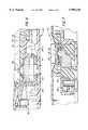
- FIG. 1is a partial section view in elevation of a portion of the instrument of FIG. 3;
- FIG. 2is a plan view of the diagnostic instrument taken along the line 2--2 in FIG. 2;
- FIG. 3is a perspective view of a diagnostic instrument in accordance with the invention.
- FIG. 4is an enlarged plan view of the portion of the diagnostic instrument of FIG. 3 where a reagent strip is inserted;
- FIG. 5is an exploded and perspective view of portions of the diagnostic instrument of FIG. 3;
- FIG. 6is a section view of the diagnostic instrument of FIG. 3 taken along the line 6--6 in FIG. 4;
- FIG. 7is a section view of the diagnostic instrument of FIG. 3 taken along the line 7--7 in FIG. 4;
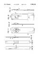
- FIGS. 8, 9 and 10are respectively back, top, and side views of a test strip for use in the instrument of FIG. 3;
- FIGS. 11, and 12are respectively top and side views of another type of test strip for use with the instrument of FIG. 3;
- FIGS. 13 and 14are respectively top and side views of a calibration strip for use with the instrument of FIG. 3;
- FIG. 15is a block diagram view of a control for a light source used in the diagnostic instrument of FIG. 3;
- FIG. 16is a plot of curves of photo detectors' sensitivity as a function of wavelength.
- the housing of the diagnostic apparatus 10comprises an upper housing 12 connected to a lower housing 14, which retains a printed circuit board 15 on which an optical assembly 17 is mounted.
- the optical assembly 17includes optical devices and an optically sealed housing 19 formed of a base plate 21 and an intermeshing upper enclosure 23 having an aperture 26' located in alignment with aperture 26 in surface 24 of a reagent strip receiving assembly 29 of apparatus 10.
- the assembly 29slides onto upper enclosure 23 starting at its front edge 31.
- a userbegins by placing the blood exposed reagent over aperture 26 and then a blood sample 22 upon a reagent pad 20 to make a diagnosis.
- the reagent pad 20is subjected to a light beam 25 alternately from light beam generators 28.1 and 28.2 located inside the optical enclosure 19 and light reflections 27 from the blood exposed reagent material are incident onto a main photo detector 32.
- the light produced by the light sources 28.1 and 28.2have wavelengths selected to enhance the ability to detect respectively the presence of glucose and fructosamine in the blood exposed reagent 22.
- the spaced apart light sources 28.1 and 28.2each produce a light beam along beam axes 44.1 and 44.2 respectively. These beams are incident onto the front surface 38 of an optical element 30.
- the optical element 30is used to direct the optical beam 25 from each of the light generators 28 onto blood reacted segment 22 of the reagent strip 18.
- the optical elementcan be a prism having a front surface 38, an upper surface 42, a bottom surface 41 and an inclined internal reflecting surface 40. Other optical elements can be used to direct light onto the reagent strip 18.
- the optical element 30extends up into an aperture 26' of the cover plate 14 so as to be essentially flush with the upper surface 43 of upper enclosure 23. This is achieved by forming the prism element 30 by molding it onto the upper enclosure 23.
- Each of the beam axes 44is oriented at an angle relative to a normal to the front surface 38 of the optical element 30.
- the reflected portion of an optical beam 25travels along a reference axis 46 to be incident on a reference detector 34.
- the part of the optical beam 25 that refracts into the optical element 30is directed onto an inclined inner reflecting surface 40 of the optical element 30.
- the inner reflecting surface 40has a reflection angle relative to the front surface 38 so that the optical beam 25 is reflected up through the upper surface 42 of optical element 30 and through apertures 26' and 26 onto the blood exposed reagent segment 22.
- the optical apertures 26 26'comprise openings in both the upper enclosure housing 23 and reagent strip receiver 29 and thus limit incidence of light onto segment 22 to the optical beam 25.
- the optical beam 25travels through apertures 26, 26', reflect off the blood reacted reagent pad 20 and travel back through the apertures 26 and 26'.
- the main detector 32which is juxtaposed with respect to the bottom surface 41 of the optical element 30, detects the reflections 27 caused by optical beam 25 from the segment 22 and produces an output signal for subsequent analysis to determine the presence and quantity of predetermined chemicals in the blood, such as glucose and fructosamine.
- the part of the optical beams 25 that are reflected off the front surface 38 of the optical element 30travel along the reference axes 46 to reference detector 34.
- the reference detector 34generates a signal indicative of the magnitude of the optical beam 25's intensity and this used, as explained with respect to FIGS. 15 and 16 to maintain the intensity output from the corresponding light source at a constant level.
- a mask 36is placed between the optical element 30 and the reference detector 34 to isolate the reference detector 34 from extraneous light signals produced by the incidence of and reflections from an optical beam 25 on various surfaces inside the apparatus 10.
- the paths through which the light beams 25 travel through the light sealed enclosure formed by upper enclosure 23 and lower base plate 21are determined by various intermeshing walls 47 and edges 49. Some of these walls and edges are formed into the base plate 21 and others are formed into the upper enclosure 23 as is evident from the views in FIGS. 2, 5, 6 and 7.
- the optical enclosureincludes two converging channels 50.1 and 50.2 for reflected beams 46.1 and 46.2. These converging channels 50 terminate at the reference detector 34 so that it can detect the reflections from the respective light beam generators 28.1 and 28.2.
- the optical beams 25are preferably created by two light emitting diodes (LED).
- One optical beam 25 from light source 28.1for example, is a red LED and is used to detect the presence of glucose.
- the other optical beam 25 from light source 28.2is a green LED and is used to detect the presence of fructosamine.
- FIGS. 8, 9 and 10show a reagent strip 18 with a reagent pad 20, bearing a reagent selected to enable the detection of glucose, and which is applied to the reagent strip 18 to overly a hole 19 through which the optical beam 25 can travel to become incident onto the reagent pad 20 reacted by a blood sample 22.
- FIGS. 11 and 12show an alternative type of test strip 18' with a reagent pad 20' selected to enable the detection of fructosamine.
- FIGS. 13 and 14show a standard reflectance strip 20" that can be used to calibrate the diagnostic apparatus 10 and determine whether it is operating accurately.
- the standard reflectance stripis placed upon the surface 24 and a diagnosis of the standard reflectance strip is made.
- the standard reflectance stripcan have a known reflectance value at some reference wavelength.
- a photo-interrupter or photo-reflective sensor 60(see FIG. 6) is used to distinguish as to what type of strip is inserted by a user into the instrument 10.
- the interrupteris a standard device such as sold by the Sharp company as its model GP2S22 subminiature photo-interrupter and is placed to detect the presence or insertion of a reagent strip 18 or 18'. The nature of the reflectance from the reagent material can be relied upon to determine which type of strip has been inserted.
- a userfirst turns the apparatus 10 on and then the reagent strip 18 is placed upon the surface 24.
- a drop of blood 22is placed upon the reagent pad 20 of the reagent strip 18.
- the diagnostic apparatus 10then makes a diagnosis of the blood sample for the presence of predetermined chemicals, such as glucose or fructosamine.
- the diagnostic apparatus 10will then alert the user of the amount of those chemicals found in the blood sample.
- a key aspect of the inventioninvolves the ability to distinguish between glucose and fructosamine chemicals on blood reacted reagent pads 20. This requires a precise control over the light sources used to illuminate the reagent pads 20 even when the light sources' output wavelengths tend to shift with age, temperature and variations in current drives. Hence, a precise control over the emitted light outputs is obtained with the use of the reference photo detector 34 and a control circuit 80 as illustrated in FIGS. 15 and using a photo detector having sensitivity characteristics as for example illustrated with curve 78 in FIG. 16.
- the reference detector 34is connected in a feedback control loop 82 to maintain the intensity output from the light source 28.1 at a constant level. This is obtained by coupling the output signal from reference detector 34 to the negative input 84 of a comparison amplifier 86 and comparing this signal with an alternating signal on line 89 that is produced by a level shifter 91 in response to a signal on line 88 from microprocessor 90.
- Level shifter 91is used to set both the peak to peak amplitude and the DC bias level of the controlling signal on line 89. This DC bias level allows the control loop to compensate for interfering light sources, such as sunlight or room lights, which may be incident on reference detector 34.
- the output of a typical silicon photo detectorwould also increase.
- the reflectance measured with detector 32would also increase as the wavelength increases, thus causing an erroneous measurement.
- a photo detector which has a blue enhanced outputcan be, for example, a silicon pin type photodiode identified as BPW 34B made by the Siemens Company of Germany.
- the output signal from main detector 32 on line 94represents an accurate indication of the reflectance from the reacted reagent 20 on a strip 18.
- This degree of wavelength compensationcan be altered by using different types of detectors 32 and 34 or by simulating different types of detectors by using different optical filters, not shown, in front of or integral to the detectors 32 or 34. For example, if the sensitivity as a function of wavelength of the main detector 32 rises more slowly with increasing wavelength than the sensitivity of the reference detector 34 (by using a blue enhanced detector for the main detector 32, for exampie) the main detector 32 will no longer completely make up for the reduction in optical power effected by the reference detector's control loop 82. This will lead to a decrease in the reflectance measured by the main detector 32 as the light source's wavelength increases. This decrease can be used to correct for the increase in reflectance of the test strip and any increase in transmittance of the optical system. If more or less correction is required dyes can also be added to the optical system by including an appropriate dye in the plastic molded optical element 30 during its molding to the enclosure 23.
- one of the two light sources 28is shown. It is to be understood that both light sources are alternately empowered and that control loop 82 is used to maintain the output power level constant for each light source 28.
- the sharing of the same circuitryis done by switching the empowering signal on line 88 from the microprocessor 90 and activating an appropriate switch, not shown, to energize the other light source 28.2 while de-activating light source 28.1.
- Signals from the main detector 32are suitably amplified by ac coupled amplifiers 96 and 98 and the resulting signal derived by a demodulator 100.
- a low pass filter 102then provides the main detector's signal to an analog to digital converter 104 for entry and signal processing by microprocessor 90. The latter can provide an indication of the measured reflectance and chemical in a display 110.
- Current control through a light source 28is obtained with a suitable transistor or other amplifier 112 placed in series with the LED 28.
Landscapes
- Physics & Mathematics (AREA)
- Health & Medical Sciences (AREA)
- Life Sciences & Earth Sciences (AREA)
- Chemical & Material Sciences (AREA)
- Analytical Chemistry (AREA)
- Biochemistry (AREA)
- General Health & Medical Sciences (AREA)
- General Physics & Mathematics (AREA)
- Immunology (AREA)
- Pathology (AREA)
- Molecular Biology (AREA)
- Engineering & Computer Science (AREA)
- Chemical Kinetics & Catalysis (AREA)
- Plasma & Fusion (AREA)
- Investigating Or Analysing Materials By Optical Means (AREA)
- Investigating Or Analysing Biological Materials (AREA)
- Investigating Or Analysing Materials By The Use Of Chemical Reactions (AREA)
Abstract
Description
Claims (3)
Priority Applications (2)
| Application Number | Priority Date | Filing Date | Title |
|---|---|---|---|
| US09/059,082US5995236A (en) | 1998-04-13 | 1998-04-13 | Blood fluid characteristics analysis instrument |
| US09/379,130US6201607B1 (en) | 1998-04-13 | 1999-08-20 | Blood fluid characteristics analysis instrument |
Applications Claiming Priority (1)
| Application Number | Priority Date | Filing Date | Title |
|---|---|---|---|
| US09/059,082US5995236A (en) | 1998-04-13 | 1998-04-13 | Blood fluid characteristics analysis instrument |
Related Child Applications (1)
| Application Number | Title | Priority Date | Filing Date |
|---|---|---|---|
| US09/379,130DivisionUS6201607B1 (en) | 1998-04-13 | 1999-08-20 | Blood fluid characteristics analysis instrument |
Publications (1)
| Publication Number | Publication Date |
|---|---|
| US5995236Atrue US5995236A (en) | 1999-11-30 |
Family
ID=22020741
Family Applications (2)
| Application Number | Title | Priority Date | Filing Date |
|---|---|---|---|
| US09/059,082Expired - LifetimeUS5995236A (en) | 1998-04-13 | 1998-04-13 | Blood fluid characteristics analysis instrument |
| US09/379,130Expired - Fee RelatedUS6201607B1 (en) | 1998-04-13 | 1999-08-20 | Blood fluid characteristics analysis instrument |
Family Applications After (1)
| Application Number | Title | Priority Date | Filing Date |
|---|---|---|---|
| US09/379,130Expired - Fee RelatedUS6201607B1 (en) | 1998-04-13 | 1999-08-20 | Blood fluid characteristics analysis instrument |
Country Status (1)
| Country | Link |
|---|---|
| US (2) | US5995236A (en) |
Cited By (35)
| Publication number | Priority date | Publication date | Assignee | Title |
|---|---|---|---|---|
| WO2000025111A1 (en)* | 1998-10-27 | 2000-05-04 | Umm Electronics, Inc. | Apparatus measuring reflectance of strips having non-uniform color |
| USD447713S1 (en) | 1998-12-08 | 2001-09-11 | Provalis Diagnostics Limited | Spectrophotometer |
| WO2001073405A1 (en)* | 2000-03-24 | 2001-10-04 | Umm Electronics, Inc. | Symmetric optical analysis device |
| US6458326B1 (en) | 1999-11-24 | 2002-10-01 | Home Diagnostics, Inc. | Protective test strip platform |
| USD467349S1 (en) | 2001-09-28 | 2002-12-17 | Orasure Technologies, Inc. | Analyzer |
| US6514460B1 (en)* | 1999-07-28 | 2003-02-04 | Abbott Laboratories | Luminous glucose monitoring device |
| US6525330B2 (en) | 2001-02-28 | 2003-02-25 | Home Diagnostics, Inc. | Method of strip insertion detection |
| US6541266B2 (en) | 2001-02-28 | 2003-04-01 | Home Diagnostics, Inc. | Method for determining concentration of an analyte in a test strip |
| US6562625B2 (en) | 2001-02-28 | 2003-05-13 | Home Diagnostics, Inc. | Distinguishing test types through spectral analysis |
| US20030210390A1 (en)* | 2002-05-07 | 2003-11-13 | O'mahony John J. | Blood leak detector for extracorporeal treatment system |
| US6707554B1 (en)* | 1998-09-29 | 2004-03-16 | Roche Diagnostics Gmbh | Method for the photometric analysis of test elements |
| US20040079135A1 (en)* | 2000-02-18 | 2004-04-29 | Yoshiharu Sato | Check chip for sensor measuring device |
| US6753187B2 (en)* | 2001-05-09 | 2004-06-22 | Lifescan, Inc. | Optical component based temperature measurement in analyte detection devices |
| US20040220457A1 (en)* | 2003-05-02 | 2004-11-04 | Burd John F. | Methods and device for non-invasive analyte measurement |
| US20050026302A1 (en)* | 2003-07-28 | 2005-02-03 | Suyue Qian | Combining transmittance detection and chromatographic strip techniques providing a simple, easy, sensitive, accurate, fast and inexpensive way to quantitate analytes in biological fluid |
| US20050085701A1 (en)* | 2003-10-21 | 2005-04-21 | Burd John F. | Methods for non-invasive analyte measurement from the conjunctiva |
| US6958039B2 (en) | 2003-05-02 | 2005-10-25 | Oculir, Inc. | Method and instruments for non-invasive analyte measurement |
| US20060008896A1 (en)* | 2004-07-09 | 2006-01-12 | Nazareth Albert R | Electronic analyte assaying device |
| US20060176483A1 (en)* | 2001-11-20 | 2006-08-10 | Heiko Rudolf | Optical measuring device for test strips |
| US20070154223A1 (en)* | 2000-05-12 | 2007-07-05 | Newell Laurence J | Synchronizing nodes in an optical communications system utilizing frequency division multiplexing |
| US20080144022A1 (en)* | 2005-06-22 | 2008-06-19 | Jochen Schulat | Analysis system for analyzing a sample on an analytical test element |
| US20080267445A1 (en)* | 2007-04-18 | 2008-10-30 | Dale Capewell | Chemistry strip reader and method |
| US20080267446A1 (en)* | 2007-04-18 | 2008-10-30 | Dale Capewell | Chemistry strip reader and method |
| US20090027682A1 (en)* | 1996-04-30 | 2009-01-29 | Hebert Raymond T | Method and Device For Measuring Reflected Optical Radiation |
| US20100098587A1 (en)* | 2000-09-25 | 2010-04-22 | Koji Miyoshi | Chromatography quantitative measuring apparatus |
| US20120281219A1 (en)* | 2009-11-18 | 2012-11-08 | Roche Diagnostics Operations, Inc. | Method and device for analyzing a body fluid |
| CN107607491A (en)* | 2017-11-06 | 2018-01-19 | 崔宝藏 | Dry chemistry reagent light reflectivity detection means |
| US10684271B2 (en) | 2016-01-29 | 2020-06-16 | Insulet Corporation | Diagnostic medical device and methods of use thereof |
| US11305333B2 (en) | 2020-03-31 | 2022-04-19 | Insulet Corporation | Methods for forming low stress component for medical devices |
| USD971416S1 (en) | 2016-06-03 | 2022-11-29 | Insulet Corporation | Overlay for drug delivery device |
| US11725741B2 (en) | 2018-07-17 | 2023-08-15 | Insulet Corporation | Low force valves for drug delivery pumps |
| USD1007518S1 (en) | 2017-03-14 | 2023-12-12 | Insulet Corporation | Display screen with a graphical user interface |
| USD1010662S1 (en) | 2017-03-14 | 2024-01-09 | Insulet Corporation | Display screen with a graphical user interface |
| US12097352B2 (en) | 2020-08-27 | 2024-09-24 | Insulet Corporation | Wearable micro-dosing drug delivery device |
| US12406760B2 (en) | 2021-06-07 | 2025-09-02 | Insulet Corporation | Exercise safety prediction based on physiological conditions |
Families Citing this family (37)
| Publication number | Priority date | Publication date | Assignee | Title |
|---|---|---|---|---|
| US7390667B2 (en) | 1997-12-22 | 2008-06-24 | Roche Diagnostics Operations, Inc. | System and method for analyte measurement using AC phase angle measurements |
| US8071384B2 (en) | 1997-12-22 | 2011-12-06 | Roche Diagnostics Operations, Inc. | Control and calibration solutions and methods for their use |
| US7407811B2 (en) | 1997-12-22 | 2008-08-05 | Roche Diagnostics Operations, Inc. | System and method for analyte measurement using AC excitation |
| US7494816B2 (en) | 1997-12-22 | 2009-02-24 | Roche Diagnostic Operations, Inc. | System and method for determining a temperature during analyte measurement |
| US20040018114A1 (en)* | 2002-07-26 | 2004-01-29 | Chia-Lin Wang | Test strip holder for a reagent test strip |
| US7118713B2 (en)* | 2003-06-03 | 2006-10-10 | Bayer Healthcare Llc | Tray assembly for optical inspection apparatus |
| US7718439B2 (en) | 2003-06-20 | 2010-05-18 | Roche Diagnostics Operations, Inc. | System and method for coding information on a biosensor test strip |
| US7597793B2 (en) | 2003-06-20 | 2009-10-06 | Roche Operations Ltd. | System and method for analyte measurement employing maximum dosing time delay |
| US7452457B2 (en) | 2003-06-20 | 2008-11-18 | Roche Diagnostics Operations, Inc. | System and method for analyte measurement using dose sufficiency electrodes |
| US7488601B2 (en) | 2003-06-20 | 2009-02-10 | Roche Diagnostic Operations, Inc. | System and method for determining an abused sensor during analyte measurement |
| US7604721B2 (en) | 2003-06-20 | 2009-10-20 | Roche Diagnostics Operations, Inc. | System and method for coding information on a biosensor test strip |
| US8148164B2 (en) | 2003-06-20 | 2012-04-03 | Roche Diagnostics Operations, Inc. | System and method for determining the concentration of an analyte in a sample fluid |
| US8058077B2 (en) | 2003-06-20 | 2011-11-15 | Roche Diagnostics Operations, Inc. | Method for coding information on a biosensor test strip |
| US7645373B2 (en) | 2003-06-20 | 2010-01-12 | Roche Diagnostic Operations, Inc. | System and method for coding information on a biosensor test strip |
| US7645421B2 (en) | 2003-06-20 | 2010-01-12 | Roche Diagnostics Operations, Inc. | System and method for coding information on a biosensor test strip |
| US8206565B2 (en) | 2003-06-20 | 2012-06-26 | Roche Diagnostics Operation, Inc. | System and method for coding information on a biosensor test strip |
| US8147426B2 (en) | 2003-12-31 | 2012-04-03 | Nipro Diagnostics, Inc. | Integrated diagnostic test system |
| EP1713926B1 (en) | 2004-02-06 | 2012-08-01 | Bayer HealthCare, LLC | Oxidizable species as an internal reference for biosensors and method of use |
| US9176121B2 (en)* | 2004-02-13 | 2015-11-03 | Roche Diagnostics Hematology, Inc. | Identification of blood elements using inverted microscopy |
| US20050227370A1 (en)* | 2004-03-08 | 2005-10-13 | Ramel Urs A | Body fluid analyte meter & cartridge system for performing combined general chemical and specific binding assays |
| US7569126B2 (en) | 2004-06-18 | 2009-08-04 | Roche Diagnostics Operations, Inc. | System and method for quality assurance of a biosensor test strip |
| US7556723B2 (en) | 2004-06-18 | 2009-07-07 | Roche Diagnostics Operations, Inc. | Electrode design for biosensor |
| US7375813B2 (en)* | 2004-10-21 | 2008-05-20 | Eastman Kodak Company | Method and system for diffusion attenuated total reflection based concentration sensing |
| AU2011232807B2 (en)* | 2005-04-15 | 2013-07-25 | Senseonics, Incorporated | Optical-based sensing devices |
| US7308292B2 (en) | 2005-04-15 | 2007-12-11 | Sensors For Medicine And Science, Inc. | Optical-based sensing devices |
| JP5047794B2 (en)* | 2005-04-20 | 2012-10-10 | アークレイ株式会社 | Analysis device, photometric mechanism cleaning method and cleaning tool in the analysis device |
| JP5385607B2 (en) | 2005-07-20 | 2014-01-08 | バイエル・ヘルスケア・エルエルシー | Gated current measuring instrument |
| KR101577176B1 (en) | 2005-09-30 | 2015-12-14 | 바이엘 헬스케어 엘엘씨 | Gated voltammetry analyte determination |
| EP1968447A4 (en)* | 2005-11-21 | 2009-09-02 | Nir Diagnostics Inc | Modified method and apparatus for measuring analytes |
| US8696597B2 (en) | 2006-04-03 | 2014-04-15 | Nipro Diagnostics, Inc. | Diagnostic meter |
| DE102007009784A1 (en)* | 2007-02-27 | 2008-08-28 | opTricon Entwicklungsgesellschaft für optische Technologien GmbH | Device for evaluating test sample, particularly medical test sample, has radiation source for generating electromagnetic radiation, measuring instrument for measuring reflected radiation from test sample and evaluator |
| WO2009076302A1 (en) | 2007-12-10 | 2009-06-18 | Bayer Healthcare Llc | Control markers for auto-detection of control solution and methods of use |
| US8465977B2 (en)* | 2008-07-22 | 2013-06-18 | Roche Diagnostics Operations, Inc. | Method and apparatus for lighted test strip |
| JP5290058B2 (en)* | 2009-06-05 | 2013-09-18 | テルモ株式会社 | Component measuring device |
| KR20130137387A (en)* | 2012-06-07 | 2013-12-17 | (주)미코바이오메드 | Potable diagnosis device |
| US10036709B2 (en) | 2014-05-20 | 2018-07-31 | Roche Diabetes Care, Inc. | BG meter illuminated test strip |
| US20180313756A1 (en)* | 2015-11-13 | 2018-11-01 | Konica Minolta, Inc. | Method for surface plasmon resonance fluorescence analysis and device for surface plasmon resonance fluorescence analysis |
Citations (16)
| Publication number | Priority date | Publication date | Assignee | Title |
|---|---|---|---|---|
| US4523853A (en)* | 1981-09-30 | 1985-06-18 | Boehringer Mannheim Gmbh | Medical test reaction area reflected light photometric device |
| US4552458A (en)* | 1983-10-11 | 1985-11-12 | Eastman Kodak Company | Compact reflectometer |
| US4627445A (en)* | 1985-04-08 | 1986-12-09 | Garid, Inc. | Glucose medical monitoring system |
| US4632559A (en)* | 1982-11-29 | 1986-12-30 | Miles Laboratories, Inc. | Optical readhead |
| US4787398A (en)* | 1985-04-08 | 1988-11-29 | Garid, Inc. | Glucose medical monitoring system |
| US4985205A (en)* | 1988-12-28 | 1991-01-15 | Boehringer Mannheim Gmbh | Test carrier analysis system |
| US5039225A (en)* | 1988-04-01 | 1991-08-13 | Fuji Photo Film Co., Ltd. | Apparatus for measurement of reflection density |
| US5114350A (en)* | 1989-03-08 | 1992-05-19 | Cholestech Corporation | Controlled-volume assay apparatus |
| US5279294A (en)* | 1985-04-08 | 1994-01-18 | Cascade Medical, Inc. | Medical diagnostic system |
| US5321492A (en)* | 1992-08-07 | 1994-06-14 | Miles Inc. | Dual function readhead for a reflectance instrument |
| US5424545A (en)* | 1992-07-15 | 1995-06-13 | Myron J. Block | Non-invasive non-spectrophotometric infrared measurement of blood analyte concentrations |
| US5424035A (en)* | 1993-03-31 | 1995-06-13 | Boehringer Mannheim Gmbh | Test strip analysis system |
| US5518689A (en)* | 1995-09-05 | 1996-05-21 | Bayer Corporation | Diffused light reflectance readhead |
| US5563042A (en)* | 1986-08-13 | 1996-10-08 | Lifescan, Inc. | Whole blood glucose test strip |
| US5597532A (en)* | 1994-10-20 | 1997-01-28 | Connolly; James | Apparatus for determining substances contained in a body fluid |
| US5611999A (en)* | 1995-09-05 | 1997-03-18 | Bayer Corporation | Diffused light reflectance readhead |
- 1998
- 1998-04-13USUS09/059,082patent/US5995236A/ennot_activeExpired - Lifetime
- 1999
- 1999-08-20USUS09/379,130patent/US6201607B1/ennot_activeExpired - Fee Related
Patent Citations (17)
| Publication number | Priority date | Publication date | Assignee | Title |
|---|---|---|---|---|
| US4523853A (en)* | 1981-09-30 | 1985-06-18 | Boehringer Mannheim Gmbh | Medical test reaction area reflected light photometric device |
| US4632559A (en)* | 1982-11-29 | 1986-12-30 | Miles Laboratories, Inc. | Optical readhead |
| US4552458A (en)* | 1983-10-11 | 1985-11-12 | Eastman Kodak Company | Compact reflectometer |
| US4627445A (en)* | 1985-04-08 | 1986-12-09 | Garid, Inc. | Glucose medical monitoring system |
| US4637403A (en)* | 1985-04-08 | 1987-01-20 | Garid, Inc. | Glucose medical monitoring system |
| US4787398A (en)* | 1985-04-08 | 1988-11-29 | Garid, Inc. | Glucose medical monitoring system |
| US5279294A (en)* | 1985-04-08 | 1994-01-18 | Cascade Medical, Inc. | Medical diagnostic system |
| US5563042A (en)* | 1986-08-13 | 1996-10-08 | Lifescan, Inc. | Whole blood glucose test strip |
| US5039225A (en)* | 1988-04-01 | 1991-08-13 | Fuji Photo Film Co., Ltd. | Apparatus for measurement of reflection density |
| US4985205A (en)* | 1988-12-28 | 1991-01-15 | Boehringer Mannheim Gmbh | Test carrier analysis system |
| US5114350A (en)* | 1989-03-08 | 1992-05-19 | Cholestech Corporation | Controlled-volume assay apparatus |
| US5424545A (en)* | 1992-07-15 | 1995-06-13 | Myron J. Block | Non-invasive non-spectrophotometric infrared measurement of blood analyte concentrations |
| US5321492A (en)* | 1992-08-07 | 1994-06-14 | Miles Inc. | Dual function readhead for a reflectance instrument |
| US5424035A (en)* | 1993-03-31 | 1995-06-13 | Boehringer Mannheim Gmbh | Test strip analysis system |
| US5597532A (en)* | 1994-10-20 | 1997-01-28 | Connolly; James | Apparatus for determining substances contained in a body fluid |
| US5518689A (en)* | 1995-09-05 | 1996-05-21 | Bayer Corporation | Diffused light reflectance readhead |
| US5611999A (en)* | 1995-09-05 | 1997-03-18 | Bayer Corporation | Diffused light reflectance readhead |
Cited By (67)
| Publication number | Priority date | Publication date | Assignee | Title |
|---|---|---|---|---|
| US20090027682A1 (en)* | 1996-04-30 | 2009-01-29 | Hebert Raymond T | Method and Device For Measuring Reflected Optical Radiation |
| US8045169B2 (en)* | 1996-04-30 | 2011-10-25 | Bayer Healthcare Llc | Method and device for measuring reflected optical radiation |
| US6707554B1 (en)* | 1998-09-29 | 2004-03-16 | Roche Diagnostics Gmbh | Method for the photometric analysis of test elements |
| US6124585A (en)* | 1998-10-27 | 2000-09-26 | Umm Electronics, Inc. | Apparatus for measuring the reflectance of strips having non-uniform color |
| WO2000025111A1 (en)* | 1998-10-27 | 2000-05-04 | Umm Electronics, Inc. | Apparatus measuring reflectance of strips having non-uniform color |
| USD447713S1 (en) | 1998-12-08 | 2001-09-11 | Provalis Diagnostics Limited | Spectrophotometer |
| US6514460B1 (en)* | 1999-07-28 | 2003-02-04 | Abbott Laboratories | Luminous glucose monitoring device |
| US6458326B1 (en) | 1999-11-24 | 2002-10-01 | Home Diagnostics, Inc. | Protective test strip platform |
| US6979571B2 (en) | 1999-11-24 | 2005-12-27 | Home Diagnostics, Inc. | Method of using a protective test strip platform for optical meter apparatus |
| US6792791B2 (en)* | 2000-02-18 | 2004-09-21 | Matsushita Electric Industrial Co., Ltd. | Inspection chip for sensor measuring instrument |
| US20040079135A1 (en)* | 2000-02-18 | 2004-04-29 | Yoshiharu Sato | Check chip for sensor measuring device |
| WO2001073405A1 (en)* | 2000-03-24 | 2001-10-04 | Umm Electronics, Inc. | Symmetric optical analysis device |
| US20070154223A1 (en)* | 2000-05-12 | 2007-07-05 | Newell Laurence J | Synchronizing nodes in an optical communications system utilizing frequency division multiplexing |
| US7664403B2 (en) | 2000-05-12 | 2010-02-16 | Newell Laurence J | Synchronizing nodes in an optical communications system utilizing frequency division multiplexing |
| US8722425B2 (en) | 2000-09-25 | 2014-05-13 | Panasonic Corporation | Chromatography quantitative measuring apparatus |
| US8722424B2 (en) | 2000-09-25 | 2014-05-13 | Panasonic Corporation | Chromatography quantitative measuring apparatus |
| US8822230B2 (en) | 2000-09-25 | 2014-09-02 | Panasonic Healthcare Co., Ltd. | Chromatography quantitative measuring apparatus |
| US20100104475A1 (en)* | 2000-09-25 | 2010-04-29 | Koji Miyoshi | Chromatography quantitative measuring apparatus |
| US20100098591A1 (en)* | 2000-09-25 | 2010-04-22 | Koji Miyoshi | Chromatography quantitative measuring apparatus |
| US20100098587A1 (en)* | 2000-09-25 | 2010-04-22 | Koji Miyoshi | Chromatography quantitative measuring apparatus |
| US8778698B2 (en)* | 2000-09-25 | 2014-07-15 | Panasonic Healthcare Co., Ltd. | Chromatography quantitative measuring apparatus |
| US6525330B2 (en) | 2001-02-28 | 2003-02-25 | Home Diagnostics, Inc. | Method of strip insertion detection |
| US6562625B2 (en) | 2001-02-28 | 2003-05-13 | Home Diagnostics, Inc. | Distinguishing test types through spectral analysis |
| US7390665B2 (en) | 2001-02-28 | 2008-06-24 | Gilmour Steven B | Distinguishing test types through spectral analysis |
| US6541266B2 (en) | 2001-02-28 | 2003-04-01 | Home Diagnostics, Inc. | Method for determining concentration of an analyte in a test strip |
| US20040203164A1 (en)* | 2001-05-09 | 2004-10-14 | Phillip Cizdziel | Optical component based temperature measurement in analyte detection devices |
| US6753187B2 (en)* | 2001-05-09 | 2004-06-22 | Lifescan, Inc. | Optical component based temperature measurement in analyte detection devices |
| AU783326B2 (en)* | 2001-05-09 | 2005-10-13 | Lifescan, Inc. | Optical component based temperature measurement in analyte detection devices |
| USD467349S1 (en) | 2001-09-28 | 2002-12-17 | Orasure Technologies, Inc. | Analyzer |
| USD474280S1 (en) | 2001-09-28 | 2003-05-06 | Orasure Technologies, Inc. | Analyzer |
| US7623240B2 (en)* | 2001-11-20 | 2009-11-24 | Iris Deutschland Gmbh | Optical measuring device for test strips |
| US20060176483A1 (en)* | 2001-11-20 | 2006-08-10 | Heiko Rudolf | Optical measuring device for test strips |
| US20060012774A1 (en)* | 2002-05-07 | 2006-01-19 | Chf Solutions Inc. | Blood leak detector for extracorporeal treatment system |
| US7230687B2 (en)* | 2002-05-07 | 2007-06-12 | Chf Solutions Inc. | Blood leak detector for extracorporeal treatment system |
| US20030210390A1 (en)* | 2002-05-07 | 2003-11-13 | O'mahony John J. | Blood leak detector for extracorporeal treatment system |
| US6947131B2 (en)* | 2002-05-07 | 2005-09-20 | Chf Solutions, Inc. | Blood leak detector for extracorporeal treatment system |
| US6958039B2 (en) | 2003-05-02 | 2005-10-25 | Oculir, Inc. | Method and instruments for non-invasive analyte measurement |
| US20040220457A1 (en)* | 2003-05-02 | 2004-11-04 | Burd John F. | Methods and device for non-invasive analyte measurement |
| US6968222B2 (en) | 2003-05-02 | 2005-11-22 | Oculir, Inc. | Methods and device for non-invasive analyte measurement |
| US7186566B2 (en)* | 2003-07-28 | 2007-03-06 | Suyue Qian | Combining transmittance detection and chromatographic strip techniques for quantification of analyte in biological fluids |
| US20050026302A1 (en)* | 2003-07-28 | 2005-02-03 | Suyue Qian | Combining transmittance detection and chromatographic strip techniques providing a simple, easy, sensitive, accurate, fast and inexpensive way to quantitate analytes in biological fluid |
| US6975892B2 (en) | 2003-10-21 | 2005-12-13 | Oculir, Inc. | Methods for non-invasive analyte measurement from the conjunctiva |
| US20050085701A1 (en)* | 2003-10-21 | 2005-04-21 | Burd John F. | Methods for non-invasive analyte measurement from the conjunctiva |
| US8623635B2 (en) | 2004-07-09 | 2014-01-07 | Church & Dwight Co., Inc. | Electronic analyte assaying device |
| US20100239460A1 (en)* | 2004-07-09 | 2010-09-23 | Nazareth Albert R | Electronic analyte assaying device |
| US20100240149A1 (en)* | 2004-07-09 | 2010-09-23 | Nazareth Albert R | Electronic analyte assaying device |
| US10168322B2 (en) | 2004-07-09 | 2019-01-01 | Church & Dwight Co., Inc. | Electronic analyte assaying device |
| US20060008896A1 (en)* | 2004-07-09 | 2006-01-12 | Nazareth Albert R | Electronic analyte assaying device |
| US8722395B2 (en) | 2004-07-09 | 2014-05-13 | Church & Dwight Co., Inc. | Electronic analyte assaying device |
| US7763454B2 (en) | 2004-07-09 | 2010-07-27 | Church & Dwight Co., Inc. | Electronic analyte assaying device |
| US7808645B2 (en)* | 2005-06-22 | 2010-10-05 | Roche Diagnostics Operations, Inc. | Analysis system for analyzing a sample on an analytical test element |
| US20080144022A1 (en)* | 2005-06-22 | 2008-06-19 | Jochen Schulat | Analysis system for analyzing a sample on an analytical test element |
| US20080267446A1 (en)* | 2007-04-18 | 2008-10-30 | Dale Capewell | Chemistry strip reader and method |
| US20110096160A1 (en)* | 2007-04-18 | 2011-04-28 | Dale Capewell | Chemistry Strip Reader And Method |
| US8150115B2 (en) | 2007-04-18 | 2012-04-03 | Iris International, Inc. | Chemistry strip reader and method |
| US20080267445A1 (en)* | 2007-04-18 | 2008-10-30 | Dale Capewell | Chemistry strip reader and method |
| US20120281219A1 (en)* | 2009-11-18 | 2012-11-08 | Roche Diagnostics Operations, Inc. | Method and device for analyzing a body fluid |
| US8570519B2 (en)* | 2009-11-18 | 2013-10-29 | Roche Diagnostics Operations, Inc. | Method and device for analyzing a body fluid |
| US10684271B2 (en) | 2016-01-29 | 2020-06-16 | Insulet Corporation | Diagnostic medical device and methods of use thereof |
| USD971416S1 (en) | 2016-06-03 | 2022-11-29 | Insulet Corporation | Overlay for drug delivery device |
| USD1007518S1 (en) | 2017-03-14 | 2023-12-12 | Insulet Corporation | Display screen with a graphical user interface |
| USD1010662S1 (en) | 2017-03-14 | 2024-01-09 | Insulet Corporation | Display screen with a graphical user interface |
| CN107607491A (en)* | 2017-11-06 | 2018-01-19 | 崔宝藏 | Dry chemistry reagent light reflectivity detection means |
| US11725741B2 (en) | 2018-07-17 | 2023-08-15 | Insulet Corporation | Low force valves for drug delivery pumps |
| US11305333B2 (en) | 2020-03-31 | 2022-04-19 | Insulet Corporation | Methods for forming low stress component for medical devices |
| US12097352B2 (en) | 2020-08-27 | 2024-09-24 | Insulet Corporation | Wearable micro-dosing drug delivery device |
| US12406760B2 (en) | 2021-06-07 | 2025-09-02 | Insulet Corporation | Exercise safety prediction based on physiological conditions |
Also Published As
| Publication number | Publication date |
|---|---|
| US6201607B1 (en) | 2001-03-13 |
Similar Documents
| Publication | Publication Date | Title |
|---|---|---|
| US5995236A (en) | Blood fluid characteristics analysis instrument | |
| JP4630003B2 (en) | Analysis result reading device and method for executing analysis | |
| US7758812B2 (en) | Analysis system for determining an analyte concentration, taking into consideration sample-and analyte-independent light-intensity changes | |
| CA2457170C (en) | Multiwavelength readhead for use in the determination of analytes in body fluids | |
| KR100219252B1 (en) | Analytical system with very small sample detection means | |
| US4925299A (en) | Hemoglobin detector | |
| US7315378B2 (en) | Optical arrangement for assay reading device | |
| JP3868516B2 (en) | Photometer multi-detector read head | |
| JP3054756B2 (en) | measuring device | |
| US7008795B2 (en) | Multi-way LED-based chemochromic sensor | |
| US7768645B2 (en) | Miniature optical readhead and colorimeter for analysis media | |
| JPH06511082A (en) | Dual wavelength photometer and fiber optic detector probe | |
| JPH09504872A (en) | Test strip reader | |
| KR19980024133A (en) | Test kits and devices | |
| JP4341153B2 (en) | Test paper analyzer | |
| JP2894364B2 (en) | Optical measuring device | |
| US12372516B2 (en) | Methods and compositions for lateral flow analyte assays | |
| CN109239338B (en) | Wide-range immunochromatography detection device and method | |
| AU2004202382B2 (en) | Optical arrangement for assay reading device | |
| JPH01131435A (en) | Measuring instrument for property value of liquid | |
| HK1070692B (en) | Optical arrangement for assay reading device | |
| HK1066597A (en) | Multiwavelength readhead for use in the determination of analytes in body fluids | |
| HK1163815A (en) | Optical arrangement for assay reading device | |
| HK1138905A (en) | Optical arrangement for assay reading device |
Legal Events
| Date | Code | Title | Description |
|---|---|---|---|
| AS | Assignment | Owner name:MIT DEVELOPMENT CORPORATION, CONNECTICUT Free format text:ASSIGNMENT OF ASSIGNORS INTEREST;ASSIGNORS:ROTH, G. THOMAS;PAOLINI, GREGORY P.;REEL/FRAME:009107/0751 Effective date:19980408 | |
| STCF | Information on status: patent grant | Free format text:PATENTED CASE | |
| AS | Assignment | Owner name:BANK OF AMERICA, N.A., NORTH CAROLINA Free format text:SECURITY INTEREST;ASSIGNOR:HDI DEVELOPMENT CORP. (F/K/A MIT DEVELOPMENT CORPORATION);REEL/FRAME:010506/0110 Effective date:19991216 | |
| AS | Assignment | Owner name:HOME DIAGNOSTICS, INC., FLORIDA Free format text:MERGER;ASSIGNOR:HDI DEVELOPMENT CORP. (F/K/A MIT DEVELOPMENT CORPORATION);REEL/FRAME:010685/0246 Effective date:19991223 | |
| FEPP | Fee payment procedure | Free format text:PAYOR NUMBER ASSIGNED (ORIGINAL EVENT CODE: ASPN); ENTITY STATUS OF PATENT OWNER: SMALL ENTITY | |
| AS | Assignment | Owner name:CAPITALSOURCE FINANCE LLC, MARYLAND Free format text:SECURITY AGREEMENT;ASSIGNOR:HOME DIAGNOSTICS, INC.;REEL/FRAME:013248/0115 Effective date:20020903 Owner name:HOME DIAGNOSTICS, INC., FLORIDA Free format text:ASSIGNMENT OF ASSIGNORS INTEREST;ASSIGNOR:BANK OF AMERICA, N.A.;REEL/FRAME:013248/0110 Effective date:20020829 | |
| AS | Assignment | Owner name:ALBION ALLIANCE MEZZANINE FUND II, L.P., NEW YORK Free format text:SECURITY INTEREST;ASSIGNOR:HOME DIAGNOSTICS, INC.;REEL/FRAME:013343/0679 Effective date:20020903 | |
| FPAY | Fee payment | Year of fee payment:4 | |
| AS | Assignment | Owner name:HOME DIAGNOSTICS, INC., FLORIDA Free format text:RELEASE AND TERMINATION OF SECURITY AGREEMENT ACCORDING TO PAYOFF LETTER ATTACHED HERETO AS EXHIBIT "A";ASSIGNOR:CAPITAL SOURCE FINANCE LLC;REEL/FRAME:014097/0603 Effective date:20031031 Owner name:WACHOVIA BANK, NATIONAL ASSOCIATION, FLORIDA Free format text:SECURITY INTEREST;ASSIGNOR:HOME DIAGNOSTICS, INC.;REEL/FRAME:014097/0634 Effective date:20031031 | |
| FPAY | Fee payment | Year of fee payment:8 | |
| AS | Assignment | Owner name:HOME DIAGNOSTICS, INC.,FLORIDA Free format text:SECURITY AGREEMENT;ASSIGNOR:ALBION ALLIANCE MEZZANINE FUND II, L.P.;REEL/FRAME:023950/0029 Effective date:20040916 | |
| AS | Assignment | Owner name:HOME DIAGNOSTICS, INC.,FLORIDA Free format text:SECURITY AGREEMENT;ASSIGNOR:WACHOVIA BANK, NATIONAL ASSOCIATION;REEL/FRAME:024035/0351 Effective date:20100224 Owner name:HOME DIAGNOSTICS, INC., FLORIDA Free format text:SECURITY AGREEMENT;ASSIGNOR:WACHOVIA BANK, NATIONAL ASSOCIATION;REEL/FRAME:024035/0351 Effective date:20100224 | |
| AS | Assignment | Owner name:NIPRO DIAGNOSTICS, INC., FLORIDA Free format text:CHANGE OF NAME;ASSIGNOR:HOME DIAGNOSTICS, INC.;REEL/FRAME:024678/0455 Effective date:20100607 | |
| FPAY | Fee payment | Year of fee payment:12 | |
| AS | Assignment | Owner name:REGIONS BANK, FLORIDA Free format text:SECURITY AGREEMENT;ASSIGNOR:NIPRO DIAGNOSTICS, INC.;REEL/FRAME:028840/0948 Effective date:20120822 | |
| AS | Assignment | Owner name:NIPRO DIAGNOSTICS, INC., FLORIDA Free format text:RELEASE BY SECURED PARTY;ASSIGNOR:REGIONS BANK;REEL/FRAME:031581/0955 Effective date:20131101 Owner name:WELLS FARGO BANK, NATIONAL ASSOCIATION, AS ADMINIS Free format text:SECURITY AGREEMENT;ASSIGNOR:NIPRO DIAGNOSTICS, INC.;REEL/FRAME:031580/0094 Effective date:20131101 | |
| AS | Assignment | Owner name:TRIVIDIA HEALTH, INC., FLORIDA Free format text:CHANGE OF NAME;ASSIGNOR:NIPRO DIAGNOSTICS, INC.;REEL/FRAME:038002/0867 Effective date:20160107 |