US5994816A - Thermal arched beam microelectromechanical devices and associated fabrication methods - Google Patents
Thermal arched beam microelectromechanical devices and associated fabrication methodsDownload PDFInfo
- Publication number
- US5994816A US5994816AUS08/936,598US93659897AUS5994816AUS 5994816 AUS5994816 AUS 5994816AUS 93659897 AUS93659897 AUS 93659897AUS 5994816 AUS5994816 AUS 5994816A
- Authority
- US
- United States
- Prior art keywords
- actuator
- microelectromechanical
- mems
- actuator member
- contacts
- Prior art date
- Legal status (The legal status is an assumption and is not a legal conclusion. Google has not performed a legal analysis and makes no representation as to the accuracy of the status listed.)
- Expired - Lifetime
Links
Images


Classifications
- F—MECHANICAL ENGINEERING; LIGHTING; HEATING; WEAPONS; BLASTING
- F16—ENGINEERING ELEMENTS AND UNITS; GENERAL MEASURES FOR PRODUCING AND MAINTAINING EFFECTIVE FUNCTIONING OF MACHINES OR INSTALLATIONS; THERMAL INSULATION IN GENERAL
- F16K—VALVES; TAPS; COCKS; ACTUATING-FLOATS; DEVICES FOR VENTING OR AERATING
- F16K99/00—Subject matter not provided for in other groups of this subclass
- F16K99/0001—Microvalves
- B—PERFORMING OPERATIONS; TRANSPORTING
- B81—MICROSTRUCTURAL TECHNOLOGY
- B81B—MICROSTRUCTURAL DEVICES OR SYSTEMS, e.g. MICROMECHANICAL DEVICES
- B81B3/00—Devices comprising flexible or deformable elements, e.g. comprising elastic tongues or membranes
- B81B3/0018—Structures acting upon the moving or flexible element for transforming energy into mechanical movement or vice versa, i.e. actuators, sensors, generators
- B81B3/0024—Transducers for transforming thermal into mechanical energy or vice versa, e.g. thermal or bimorph actuators
- B—PERFORMING OPERATIONS; TRANSPORTING
- B81—MICROSTRUCTURAL TECHNOLOGY
- B81B—MICROSTRUCTURAL DEVICES OR SYSTEMS, e.g. MICROMECHANICAL DEVICES
- B81B3/00—Devices comprising flexible or deformable elements, e.g. comprising elastic tongues or membranes
- B81B3/0035—Constitution or structural means for controlling the movement of the flexible or deformable elements
- B81B3/0054—For holding or placing an element in a given position
- F—MECHANICAL ENGINEERING; LIGHTING; HEATING; WEAPONS; BLASTING
- F03—MACHINES OR ENGINES FOR LIQUIDS; WIND, SPRING, OR WEIGHT MOTORS; PRODUCING MECHANICAL POWER OR A REACTIVE PROPULSIVE THRUST, NOT OTHERWISE PROVIDED FOR
- F03G—SPRING, WEIGHT, INERTIA OR LIKE MOTORS; MECHANICAL-POWER PRODUCING DEVICES OR MECHANISMS, NOT OTHERWISE PROVIDED FOR OR USING ENERGY SOURCES NOT OTHERWISE PROVIDED FOR
- F03G7/00—Mechanical-power-producing mechanisms, not otherwise provided for or using energy sources not otherwise provided for
- F03G7/06—Mechanical-power-producing mechanisms, not otherwise provided for or using energy sources not otherwise provided for using expansion or contraction of bodies due to heating, cooling, moistening, drying or the like
- F03G7/061—Mechanical-power-producing mechanisms, not otherwise provided for or using energy sources not otherwise provided for using expansion or contraction of bodies due to heating, cooling, moistening, drying or the like characterised by the actuating element
- F03G7/06114—Mechanical-power-producing mechanisms, not otherwise provided for or using energy sources not otherwise provided for using expansion or contraction of bodies due to heating, cooling, moistening, drying or the like characterised by the actuating element using the thermal expansion or contraction of solid materials
- F—MECHANICAL ENGINEERING; LIGHTING; HEATING; WEAPONS; BLASTING
- F03—MACHINES OR ENGINES FOR LIQUIDS; WIND, SPRING, OR WEIGHT MOTORS; PRODUCING MECHANICAL POWER OR A REACTIVE PROPULSIVE THRUST, NOT OTHERWISE PROVIDED FOR
- F03G—SPRING, WEIGHT, INERTIA OR LIKE MOTORS; MECHANICAL-POWER PRODUCING DEVICES OR MECHANISMS, NOT OTHERWISE PROVIDED FOR OR USING ENERGY SOURCES NOT OTHERWISE PROVIDED FOR
- F03G7/00—Mechanical-power-producing mechanisms, not otherwise provided for or using energy sources not otherwise provided for
- F03G7/06—Mechanical-power-producing mechanisms, not otherwise provided for or using energy sources not otherwise provided for using expansion or contraction of bodies due to heating, cooling, moistening, drying or the like
- F03G7/064—Mechanical-power-producing mechanisms, not otherwise provided for or using energy sources not otherwise provided for using expansion or contraction of bodies due to heating, cooling, moistening, drying or the like characterised by its use
- F—MECHANICAL ENGINEERING; LIGHTING; HEATING; WEAPONS; BLASTING
- F15—FLUID-PRESSURE ACTUATORS; HYDRAULICS OR PNEUMATICS IN GENERAL
- F15C—FLUID-CIRCUIT ELEMENTS PREDOMINANTLY USED FOR COMPUTING OR CONTROL PURPOSES
- F15C5/00—Manufacture of fluid circuit elements; Manufacture of assemblages of such elements integrated circuits
- F—MECHANICAL ENGINEERING; LIGHTING; HEATING; WEAPONS; BLASTING
- F16—ENGINEERING ELEMENTS AND UNITS; GENERAL MEASURES FOR PRODUCING AND MAINTAINING EFFECTIVE FUNCTIONING OF MACHINES OR INSTALLATIONS; THERMAL INSULATION IN GENERAL
- F16K—VALVES; TAPS; COCKS; ACTUATING-FLOATS; DEVICES FOR VENTING OR AERATING
- F16K99/00—Subject matter not provided for in other groups of this subclass
- F16K99/0001—Microvalves
- F16K99/0003—Constructional types of microvalves; Details of the cutting-off member
- F16K99/0011—Gate valves or sliding valves
- F—MECHANICAL ENGINEERING; LIGHTING; HEATING; WEAPONS; BLASTING
- F16—ENGINEERING ELEMENTS AND UNITS; GENERAL MEASURES FOR PRODUCING AND MAINTAINING EFFECTIVE FUNCTIONING OF MACHINES OR INSTALLATIONS; THERMAL INSULATION IN GENERAL
- F16K—VALVES; TAPS; COCKS; ACTUATING-FLOATS; DEVICES FOR VENTING OR AERATING
- F16K99/00—Subject matter not provided for in other groups of this subclass
- F16K99/0001—Microvalves
- F16K99/0034—Operating means specially adapted for microvalves
- F16K99/0042—Electric operating means therefor
- F16K99/0044—Electric operating means therefor using thermo-electric means
- H—ELECTRICITY
- H01—ELECTRIC ELEMENTS
- H01H—ELECTRIC SWITCHES; RELAYS; SELECTORS; EMERGENCY PROTECTIVE DEVICES
- H01H1/00—Contacts
- H01H1/0036—Switches making use of microelectromechanical systems [MEMS]
- H—ELECTRICITY
- H01—ELECTRIC ELEMENTS
- H01H—ELECTRIC SWITCHES; RELAYS; SELECTORS; EMERGENCY PROTECTIVE DEVICES
- H01H61/00—Electrothermal relays
- H01H61/02—Electrothermal relays wherein the thermally-sensitive member is heated indirectly, e.g. resistively, inductively
- B—PERFORMING OPERATIONS; TRANSPORTING
- B81—MICROSTRUCTURAL TECHNOLOGY
- B81B—MICROSTRUCTURAL DEVICES OR SYSTEMS, e.g. MICROMECHANICAL DEVICES
- B81B2201/00—Specific applications of microelectromechanical systems
- B81B2201/03—Microengines and actuators
- B81B2201/031—Thermal actuators
- B—PERFORMING OPERATIONS; TRANSPORTING
- B81—MICROSTRUCTURAL TECHNOLOGY
- B81B—MICROSTRUCTURAL DEVICES OR SYSTEMS, e.g. MICROMECHANICAL DEVICES
- B81B2201/00—Specific applications of microelectromechanical systems
- B81B2201/05—Microfluidics
- B81B2201/054—Microvalves
- B—PERFORMING OPERATIONS; TRANSPORTING
- B81—MICROSTRUCTURAL TECHNOLOGY
- B81B—MICROSTRUCTURAL DEVICES OR SYSTEMS, e.g. MICROMECHANICAL DEVICES
- B81B2203/00—Basic microelectromechanical structures
- B81B2203/01—Suspended structures, i.e. structures allowing a movement
- B81B2203/0109—Bridges
- B—PERFORMING OPERATIONS; TRANSPORTING
- B81—MICROSTRUCTURAL TECHNOLOGY
- B81B—MICROSTRUCTURAL DEVICES OR SYSTEMS, e.g. MICROMECHANICAL DEVICES
- B81B2203/00—Basic microelectromechanical structures
- B81B2203/05—Type of movement
- B81B2203/051—Translation according to an axis parallel to the substrate
- F—MECHANICAL ENGINEERING; LIGHTING; HEATING; WEAPONS; BLASTING
- F16—ENGINEERING ELEMENTS AND UNITS; GENERAL MEASURES FOR PRODUCING AND MAINTAINING EFFECTIVE FUNCTIONING OF MACHINES OR INSTALLATIONS; THERMAL INSULATION IN GENERAL
- F16K—VALVES; TAPS; COCKS; ACTUATING-FLOATS; DEVICES FOR VENTING OR AERATING
- F16K99/00—Subject matter not provided for in other groups of this subclass
- F16K99/0001—Microvalves
- F16K2099/0071—Microvalves with latching means
- F—MECHANICAL ENGINEERING; LIGHTING; HEATING; WEAPONS; BLASTING
- F16—ENGINEERING ELEMENTS AND UNITS; GENERAL MEASURES FOR PRODUCING AND MAINTAINING EFFECTIVE FUNCTIONING OF MACHINES OR INSTALLATIONS; THERMAL INSULATION IN GENERAL
- F16K—VALVES; TAPS; COCKS; ACTUATING-FLOATS; DEVICES FOR VENTING OR AERATING
- F16K99/00—Subject matter not provided for in other groups of this subclass
- F16K2099/0073—Fabrication methods specifically adapted for microvalves
- F16K2099/0074—Fabrication methods specifically adapted for microvalves using photolithography, e.g. etching
- F—MECHANICAL ENGINEERING; LIGHTING; HEATING; WEAPONS; BLASTING
- F16—ENGINEERING ELEMENTS AND UNITS; GENERAL MEASURES FOR PRODUCING AND MAINTAINING EFFECTIVE FUNCTIONING OF MACHINES OR INSTALLATIONS; THERMAL INSULATION IN GENERAL
- F16K—VALVES; TAPS; COCKS; ACTUATING-FLOATS; DEVICES FOR VENTING OR AERATING
- F16K99/00—Subject matter not provided for in other groups of this subclass
- F16K2099/0073—Fabrication methods specifically adapted for microvalves
- F16K2099/008—Multi-layer fabrications
- F—MECHANICAL ENGINEERING; LIGHTING; HEATING; WEAPONS; BLASTING
- F16—ENGINEERING ELEMENTS AND UNITS; GENERAL MEASURES FOR PRODUCING AND MAINTAINING EFFECTIVE FUNCTIONING OF MACHINES OR INSTALLATIONS; THERMAL INSULATION IN GENERAL
- F16K—VALVES; TAPS; COCKS; ACTUATING-FLOATS; DEVICES FOR VENTING OR AERATING
- F16K99/00—Subject matter not provided for in other groups of this subclass
- F16K99/0001—Microvalves
- F16K99/0034—Operating means specially adapted for microvalves
- G—PHYSICS
- G02—OPTICS
- G02B—OPTICAL ELEMENTS, SYSTEMS OR APPARATUS
- G02B6/00—Light guides; Structural details of arrangements comprising light guides and other optical elements, e.g. couplings
- G02B6/24—Coupling light guides
- G02B6/36—Mechanical coupling means
- G02B6/38—Mechanical coupling means having fibre to fibre mating means
- G02B6/3801—Permanent connections, i.e. wherein fibres are kept aligned by mechanical means
- G02B6/3803—Adjustment or alignment devices for alignment prior to splicing
- G—PHYSICS
- G02—OPTICS
- G02B—OPTICAL ELEMENTS, SYSTEMS OR APPARATUS
- G02B6/00—Light guides; Structural details of arrangements comprising light guides and other optical elements, e.g. couplings
- G02B6/24—Coupling light guides
- G02B6/42—Coupling light guides with opto-electronic elements
- G02B6/4201—Packages, e.g. shape, construction, internal or external details
- G02B6/4219—Mechanical fixtures for holding or positioning the elements relative to each other in the couplings; Alignment methods for the elements, e.g. measuring or observing methods especially used therefor
- G02B6/422—Active alignment, i.e. moving the elements in response to the detected degree of coupling or position of the elements
- G02B6/4226—Positioning means for moving the elements into alignment, e.g. alignment screws, deformation of the mount
- H—ELECTRICITY
- H01—ELECTRIC ELEMENTS
- H01H—ELECTRIC SWITCHES; RELAYS; SELECTORS; EMERGENCY PROTECTIVE DEVICES
- H01H1/00—Contacts
- H01H1/0036—Switches making use of microelectromechanical systems [MEMS]
- H01H2001/0042—Bistable switches, i.e. having two stable positions requiring only actuating energy for switching between them, e.g. with snap membrane or by permanent magnet
- H01H2001/0047—Bistable switches, i.e. having two stable positions requiring only actuating energy for switching between them, e.g. with snap membrane or by permanent magnet operable only by mechanical latching
- H—ELECTRICITY
- H01—ELECTRIC ELEMENTS
- H01H—ELECTRIC SWITCHES; RELAYS; SELECTORS; EMERGENCY PROTECTIVE DEVICES
- H01H1/00—Contacts
- H01H1/0036—Switches making use of microelectromechanical systems [MEMS]
- H01H2001/0068—Switches making use of microelectromechanical systems [MEMS] with multi dimensional movement, i.e. the movable actuator performing movements in at least two different directions
- H—ELECTRICITY
- H01—ELECTRIC ELEMENTS
- H01H—ELECTRIC SWITCHES; RELAYS; SELECTORS; EMERGENCY PROTECTIVE DEVICES
- H01H61/00—Electrothermal relays
- H01H2061/006—Micromechanical thermal relay
- H—ELECTRICITY
- H01—ELECTRIC ELEMENTS
- H01H—ELECTRIC SWITCHES; RELAYS; SELECTORS; EMERGENCY PROTECTIVE DEVICES
- H01H61/00—Electrothermal relays
- H—ELECTRICITY
- H01—ELECTRIC ELEMENTS
- H01H—ELECTRIC SWITCHES; RELAYS; SELECTORS; EMERGENCY PROTECTIVE DEVICES
- H01H67/00—Electrically-operated selector switches
- H01H67/22—Switches without multi-position wipers
- H01H67/26—Co-ordinate-type selector switches not having relays at cross-points but involving mechanical movement, e.g. cross-bar switch, code-bar switch
- H—ELECTRICITY
- H01—ELECTRIC ELEMENTS
- H01H—ELECTRIC SWITCHES; RELAYS; SELECTORS; EMERGENCY PROTECTIVE DEVICES
- H01H9/00—Details of switching devices, not covered by groups H01H1/00 - H01H7/00
- H01H9/14—Adaptation for built-in safety spark gaps
- Y—GENERAL TAGGING OF NEW TECHNOLOGICAL DEVELOPMENTS; GENERAL TAGGING OF CROSS-SECTIONAL TECHNOLOGIES SPANNING OVER SEVERAL SECTIONS OF THE IPC; TECHNICAL SUBJECTS COVERED BY FORMER USPC CROSS-REFERENCE ART COLLECTIONS [XRACs] AND DIGESTS
- Y10—TECHNICAL SUBJECTS COVERED BY FORMER USPC
- Y10T—TECHNICAL SUBJECTS COVERED BY FORMER US CLASSIFICATION
- Y10T29/00—Metal working
- Y10T29/49—Method of mechanical manufacture
- Y10T29/49002—Electrical device making
- Y10T29/49105—Switch making
Definitions
- the present inventionrelates generally to microelectromechanical devices and, more particularly, to microelectromechanical devices that include thermal arched beam actuators and related fabrication methods.
- MEMSMicroelectromechanical systems
- electromechanical devicessuch as relays, actuators, valves and sensors.
- MEMS devicesare potentially low cost devices, due to the use of microelectronic fabrication techniques. New functionality may also be provided because MEMS devices can be much smaller than conventional electromechanical devices.
- MEMS actuatorsMany potential applications of MEMS technology utilize MEMS actuators. For example, many sensors, valves and positioners use actuators for movement. If properly designed, MEMS actuators can produce useful forces and displacement, while consuming reasonable amounts of power. Many configurations of MEMS actuators have been proposed. For example, U.S. Pat. No. 5,475,318 to Marcus et al. entitled “Microprobe”, discloses cantilever bimorph microprobes and doubly supported beam bimorph microprobes. In addition, an article entitled “Silicon Fusion Bonding and Deep Reactive Ion Etching; A New Technology For Microstructures", by Erno H. Klaassen, et al.
- the thermal actuator of the Klaassen articlecan also a include a center post that connects the plurality of arched beams and serves to push against the workpiece.
- the Klaassen articlealso describes a capacitive accelerometer structure that utilizes the thermal actuators to vary the spacing between a number of interdigitated fingers.
- MEMS actuatorsthat have previously been proposed, a number of existing and contemplated MEMS systems, such as relays, actuators, valves and sensors, require more sophisticated actuators that provide useful forces and displacements while consuming reasonable amounts of power in an efficient manner. Since it is desirable that the resulting MEMS systems be fabricated with batch processing, it is also preferred that the microelectronic fabrication techniques for manufacturing the resulting MEMS systems be affordable, repeatable and reliable.
- the MEMS devices of the present inventioninclude a particularly advantageous MEMS actuator, as well as a family of other MEMS devices, such as relays, switching arrays and valves, that include one or more MEMS actuators.
- a method of fabricating a MEMS actuatoris also provided according of the present invention.
- a MEMS structurehereinafter referred to as a MEMS actuator, includes a microelectronic substrate, spaced apart supports on the substrate and a metallic arched beam extending between the spaced apart supports.
- the MEMS actuatoralso includes means for heating the arched beam to cause further arching of the beam.
- the heating meansincludes a heater extending between first and second opposed ends which, in turn, are disposed upon the microelectronic substrate.
- the metallic arched beamextends over and is spaced, albeit slightly, from the heater such that the heat generated by the heater causes the metallic arched beam to further arch.
- the MEMS actuator of this advantageous embodimenteffectively converts the heat generated by the heater into mechanical motion of the metallic arched beam.
- numerous MEMS devicescan incorporate the MEMS actuator of the present invention in order to provide a controllable force and displacement without consuming significant amounts of power.
- the heaterpreferably includes an at least partially conductive material having high resistivity, such as polysilicon, titanium or tungsten, surrounded by a dielectric material, such as silicon nitride or silicon dioxide.
- the dielectric material surrounding the at least partially conductive materialcooperates with an air gap defined between the metallic arched beam and the heater to electrically isolate the metallic arched beam from the at least partially conductive material.
- the air gapis preferably small, such as less than about 5 microns and, more preferably, between about 1 micron and 2 microns.
- the dielectric materialis also preferably relative thin and, in one advantageous embodiment, has a thickness of about 0.5 micron.
- the MEMS actuatoralso preferably includes a lengthwise extending actuator member connected to the metallic arched beam and extending outwardly in a first direction.
- the heaterunderlies and is aligned with the actuator member in the first direction. As a result of this alignment, the heat generated by the heater of this embodiment is even more efficiently transmitted to the actuator member and, in turn, to the metallic arched beam so as to cause further arching of the arched beam.
- a MEMS relay of the present inventionincludes a microelectronic substrate, a first pair of contacts on the substrate and a first MEMS actuator on the substrate for controllably establishing electrical contact between the pair of contacts.
- the actuator member of the MEMS actuatorpreferably includes a lengthwise extending portion coupled to the arched beam and an enlarged contact portion, responsive to movement of the lengthwise extending portion, for establishing contact with the first pair of contacts.
- the actuator memberincluding the lengthwise extending portion and the enlarged contact portion, is a unitary structures.
- the lengthwise extending portion and the enlarged contact portion of the actuator membersare separate structures positioned such that the lengthwise extending portion will move into contact with the enlarged contact portion upon movement of the lengthwise extending portion in response to heating of the arched beams, thereby urging the enlarged contact portion into contact with the first pair of contacts.
- the actuator memberUpon actuation of the MEMS relay of the present invention, the actuator member is moved between an open position in which the actuator member is spaced from the first pair of contacts and a closed position in which the actuator member contacts the first pair of contacts and establishes an electrical connection therebetween.
- the MEMS relaypreferably includes means for holding the actuator member in position following heating of the arched beam and movement of the actuator member.
- the holding meanscan include means for applying an electrostatic force between the actuator member and the substrate, thereby holding at least a portion of the actuator member against the substrate.
- the MEMS relaycan also include at least one retaining member on the substrate and positioned so as to underlie the actuator member once the actuator member has moved in response to heating of the arched beam.
- the actuator memberalso includes a lower surface facing the substrate that defines at least one recess for cooperably receiving a respective retaining member as the actuator member is held in position, such as by an electrostatic force.
- the MEMS relaycan include latch means for latching the actuator member in position following heating of the arched beam and movement of the actuator member. By latching the actuator member in position, electrical contact will be maintained between the first pair of contacts without having to continue actuating the MEMS actuator, thereby further reducing power requirements of the MEMS relay.
- the latch meansincludes a projection extending outwardly from the actuator member and an associated latch member for cooperably engaging the outwardly extending projection upon actuation of the MEMS actuator.
- the MEMS relay of this embodimentcan also include reset means, typically including a second MEMS actuator having an actuator member that includes the latch member, for disengaging the latch member from the outwardly extending projection, thereby permitting the MEMS relay to return to a rest position.
- the MEMS relaycan also include first and second field intensification structures electrically connected to respective ones of the first pair of contacts.
- the first and second field intensification structuresare disposed in a facing relationship to thereby define a discharge gap.
- each field intensification structureincludes at least one pointed protection extending toward the other field intensification structure to more precisely define the discharge gap.
- the MEMS relayincludes a second MEMS actuator on a portion of the substrate opposite the first MEMS actuator relative to the first pair of contacts.
- the second MEMS actuatoris designed to controllably disengage the actuator member of the first MEMS actuator from the first pair of contacts in order to reopen the first pair of contacts.
- the actuator member of the second MEMS actuatorUpon heating the arched beam of the second MEMS actuator, the actuator member of the second MEMS actuator preferably moves so as to contact the actuator member of the first MEMS actuator, thereby disengaging the actuator member of the first MEMS actuator from the first pair of contacts.
- the MEMS relay of another advantageous embodimentalternately connects first and second pairs contacts.
- the MEMS relay of this embodimentincludes a substrate, first and second pairs contacts on the substrate and first and second MEMS actuators on the substrate.
- the MEMS actuatorsare positioned such that upon actuation of the first MEMS actuator, the actuator member of the first MEMS actuator cooperably engages the actuator member of the second MEMS actuator. Once engaged, electrical contact is established between the first pair of contacts in the absence of further actuation of either MEMS actuator. In contrast, electrical contact is only established between the second pair of contacts upon actuation of the second MEMS actuator.
- the end portion of the actuator member of the second MEMS actuatorpreferably includes a sleeve that opens through the end thereof.
- the end portion of the actuator member of the first MEMS actuatorpreferably includes an engagement portion for insertion through the end of the sleeve upon actuation of the first MEMS actuator.
- a MEMS switching arrayis also provided that includes a substrate and a plurality of first and second MEMS actuators positioned on the substrate such that the plurality of first MEMS actuators define respective row elements and the plurality of second MEMS actuator define respective column elements.
- each MEMS actuatoralso includes a plurality of contact members spaced along the respective actuator member and extending outwardly therefrom. Upon actuation of a pair of first and second MEMS actuators, the respective actuator members are moved so as to establish electrical contact between the respective contact members, thereby establishing a continuous electrical path between the pair of first and second MEMS actuators.
- the MEMS switching arraycan also include latch means for latching the actuator members of the respective pair of first and second MEMS actuators in position following actuation thereof. As such, electrical contact will be maintained between the respective contact members without having to continue actuating the respective pair of first and second MEMS actuators, thereby further reducing power requirements of the MEMS switching array.
- the latch meansincludes a latch member extending outwardly from each respective actuator member and a plurality of anchor members. Each anchor member is associated with a respective MEMS actuator and is positioned upon the substrate so as to cooperably engage the latch member upon actuation of the respective MEMS actuator.
- the MEMS switching arraycan also include reset means for unlatching the actuator members of the respective pair of first and second MEMS actuators such that respective contact members separate and no longer make electrical contact in the absence of further actuation of the respective pair of first and second MEMS actuators.
- the reset meansincludes first and second reset actuators for resetting the plurality of first MEMS actuators and the plurality of second MEMS actuators, respectively.
- each reset actuatorpreferably includes an actuator member having a plurality of reset members spaced therealong. The plurality of reset members engage respective actuator members of the first and second MEMS actuators upon actuation of the reset actuator, thereby disengaging the latch portions of the actuator members from the respective anchor members.
- a MEMS valveincludes a substrate defining an opening and a MEMS actuator on the substrate and having a valve plate operably coupled to the arched beam, either directly or indirectly via an actuator member, that is adapted to at least partially covering the opening in the substrate.
- the portion of the opening covered by the valve platecan be precisely controlled by moving the valve plate relative to the substrate upon actuation of the MEMS actuator.
- the MEMS valvecan also include means for holding the valve plate in position relative to the opening without requiring further actuation of the arched beam.
- the substratepreferably defines a plurality of openings and the MEMS actuator correspondingly includes a plurality of valve plates operably coupled to the arched beam and adapted to at least partially cover respective ones of the openings.
- the valve plateis preferably designed as an elongate plate that pivots about a pivot point, typically defined by a bearing post extending outwardly from the substrate, as the arched beam is heated in order to controllably adjust the portion of the opening covered by the valve plate.
- the openings defined by the substrateare preferably spaced angularly about the bearing post.
- the MEMS valve of this embodimenthas the general appearance of a fan with the pivoting valve plates serving as the fan blades.
- the MEMS valve of this embodimentcan be designed to be either normally open or normally closed.
- the present inventionalso provides an advantageous method for fabricating a MEMS structure, such as a MEMS actuator, that includes a metallic arched beam that overlies and is spaced from a heater.
- a MEMS structuresuch as a MEMS actuator
- a sacrificial plating baseis initially deposited upon a first surface of a microelectronic substrate.
- a photoresist layeris deposited on the sacrificial plating base and is patterned to open one or more windows to the sacrificial plating base.
- the windowspreferably correspond to the pair of spaced apart supports and the arched beam extending between the spaced apart supports of the resulting MEMS actuator.
- a metalsuch as nickel
- a metalis electroplated within the windows defined by the photoresist layer to form the pair of spaced apart supports and the arched beams extending between spaced apart supports.
- the photoresist layeris thereafter removed and portions of the sacrificial plating base are etched to thereby release the arched beams from the substrate.
- an oxide layercan be formed and patterned so as to underlie the arched beam, but not the spaced apart supports. As such, removal of this oxide layer will release the arched beam from the substrate.
- a heaterPrior to the depositing the sacrificial plating base upon the substrate, a heater can be formed on the first surface of the substrate. In addition, a cavity can be etched into the portion of the substrate underlying the heater, typically following the removal of the photoresist layer and the etching of the sacrificial plating base and/or the oxide layer, such that medial portions of the heater are further thermally isolated from the substrate.
- metallic arched beams having large aspect ratioscan be electroplated over a heater with a relatively small, typically 5 microns or less, spacing or air gap between the heater and the overlying metallic arched beam.
- heat generated by the heateris effectively transferred to the metallic arched beam for translation into mechanical motion of the arched beam.
- the method of the present inventioncan also advantageously cofabricate the other portions of the MEMS structures of the present invention, such as the MEMS relays, the MEMS switching arrays and the MEMS valves.
- MEMS structuresincluding the MEMS actuators, of the present invention provide significant forces and displacements while consuming reasonable amounts of power.
- the design of the MEMS actuator of the present inventionprovides efficient thermal transfer of the heat generated by the heater to the overlying metallic arched beam so as to create further arching of the metallic arched beam.
- a number of MEMS devicessuch as a variety of MEMS relays, MEMS switching arrays and MEMS valves, are also advantageously provided.
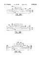
- FIG. 1is a top view of a MEMS actuator of one embodiment of the present invention that includes a heater for causing the beams to further arch.
- FIG. 2is a cross-sectional view of the MEMS actuator of FIG. 1 taken along line 2--2 in which the dashed lines indicate the plurality of branches of the sinuous heater, two of which are illustrated for purposes of discussion.
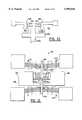
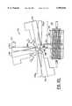
- FIG. 3is a MEMS actuator according to another embodiment of the present invention having a heater that underlies the actuator member.
- FIG. 4is a cross-sectional view of the MEMS actuator of FIG. 3 taken along line 4--4.
- FIGS. 5A-5Eare cross-sectional views illustrating the operations performed during the fabrication of a MEMS actuator of one embodiment of the present invention.
- FIGS. 6A-6Fare cross-sectional views illustrating the operations performed during the fabrication of a MEMS actuator of another embodiment of the present invention.
- FIG. 7Ais a top view and FIGS. 7B and 7C are cross-sectional views of a MEMS relay in an open position wherein the MEMS relay includes a MEMS actuator according to one embodiment of the present invention.
- FIG. 8Ais a top view and FIGS. 8B and 8C are cross-sectional views of a MEMS relay in a closed position wherein the MEMS relay includes a MEMS actuator according to one embodiment of the present invention.
- FIGS. 9A-9Care top views of a MEMS relay including a MEMS actuator according to another embodiment of the present invention that illustrates the sequential operations performed to close and open the MEMS relay.
- FIG. 10is top view of a portion of a MEMS relay of one embodiment of the present invention that includes first and second field intensification structures for providing overvoltage protection.
- FIG. 11is a top view of a MEMS relay of another embodiment of the present invention that includes latch means and reset means.
- FIG. 12is a top view of a MEMS relay of another advantageous embodiment of the present invention.
- FIG. 13is top view of a MEMS relay of yet another advantageous embodiment of the present invention.
- FIG. 14is an enlarged plan view of a portion of the MEMS relay of FIG. 13 illustrating one advantageous embodiment of the latch means.
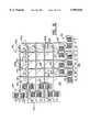
- FIG. 15is a top view of a 4 ⁇ 4 switching array in the open position according to one advantageous embodiment of the present invention.
- FIG. 16is an enlarged perspective view of a portion of the switching array of FIG. 15 illustrating one technique for permitting the actuator members of the first and second actuators to cross over.
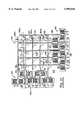
- FIG. 17is a top view of the switching array of FIG. 15 in which electrical contact has been established between the first row and the third column.
- FIG. 18is a top view of a MEMS valve of one embodiment of the present invention.
- FIGS. 19are cross-sectional views of FIG. 18 taken along line 19--19 in the open and closed positions, respectively.
- FIG. 20is a top view of a normally open fan-type MEMS valve according to another advantageous embodiment of the present invention.
- FIG. 21is a top view of a normally closed fan-type MEMS valve according to another advantageous embodiment of the present invention.
- the MEMS actuatorincludes a microelectronic substrate 32 and a pair of spaced apart supports 34 on the substrate. While the substrate can be formed of a variety of materials, the substrate is typically formed of silicon, glass or quartz.
- the spaced apart supports 34are preferably formed of metal, such as nickel, that is deposited on the substrate 32 by means of an electroplating process in order to have a high aspect ratio, as described hereinbelow.
- electroplating techniquesinclude, but are not limited to "LIGA" techniques.
- the MEMS actuator 30also includes at least one and, more preferably, a number of arched beams 36 extending between the spaced apart supports 34.
- the MEMS actuatorcan have any number and any size of arched beams, the MEMS actuator of one embodiment includes five arched beams which are 5 ⁇ m wide, 30 ⁇ m tall and 2 mm in length.
- the arched beamsare also typically formed of a conductive material which has a positive coefficient of thermal expansion so that the arched beam expands as the arched beam is heated.
- the arched beamsare preferably formed of a metal and, more preferably, are formed of nickel or a nickel-phosphorous alloy.
- the arched beamsare also preferably formed by electroplating so as to have high aspect ratios.
- the aspect ratio of the arched beamsis preferably greater than 1.5:1 and more preferably is about 3:1.
- the arched beamsare arched in a direction which preferably extends parallel to the substrate 32.
- the arched beamis freed from the substrate, typically by means of a release layer and wet etching as described hereinbelow, the arched beam remains anchored at the spaced apart support and is arched toward the desired or predetermined direction of motion.
- the MEMS actuator 30also includes means for applying heat to the arched beams 36.
- the applied heatcauses further arching of the beam as a result of the thermal expansion of the beam.
- the arching of the beampreferably occurs in the predetermined direction of motion so as to cause displacement of the arched beam.
- the MEMS actuator of the illustrated embodimentincludes an external heater 38.
- the external heaterextends between first and second opposed ends that commonly serve as contact pads for establishing electrical contact with the heater. As shown in FIG. 1, the heater of one advantageous embodiment winds back and forth in a sinuous path beneath the metallic arched beams such that heat generated by the sinuous heater heats the metallic arched beams in a relatively even fashion.
- the first and second ends of the heater 38are disposed on the substrate 32, a portion of the substrate underlying the remainder of the heater, i.e., the medial portion of the heater, can be etched or otherwise removed in order to further thermally isolate the heater from the substrate, as described hereinbelow and as shown in FIG. 2.
- the heatercan extend in a cantilevered fashion over the cavity 32a defined within the substrate or, alternatively, the cavity defined by the substrate may be covered by a diaphragm, typically formed of a dielectric material such as silicon nitride, in order to structurally support the heater while maintaining sufficient thermal isolation between the heater and the substrate.
- a medial portion of the heater extending over the cavity defined in the substratecan be further supported by link, typically also formed of a dielectric material such as silicon nitride, that bridges between the heater and another portion of the substrate.
- the heater 38generally includes a core 38a formed of an at least partially conductive material having a high resistivity, such as resistivity of at least 5 ⁇ 10 -6 ⁇ cm, and a coating 38b formed of a dielectric material surrounding the at least partially conductive material.
- the heaterincludes a core of polysilicon, titanium or tungsten that is surrounding by a coating of silicon nitride or silicon dioxide.
- the arched beams 36are electrically isolated from the at least partially conductive core of the heater by a combination of an air gap 40 and the dielectric coating of the heater.
- the air gapis preferably reduced as much as possible while still maintaining sufficient electrical isolation, such as 1,000 volts in one exemplary embodiment.
- the air gapis less than 5 microns and, more preferably, between 1 micron and 2 microns.
- the dielectric material covering the portion of the at least partially conductive material that faces the arched beamhas a thickness of about 0.5 micron.
- the MEMS actuator 30 of the present inventionalso preferably includes a lengthwise extending actuator member 42 coupled to the arched beams 36 and extending outwardly therefrom.
- the actuator membermechanically couples the plurality of arched beams at a point between the spaced apart supports 34 as shown in FIG. 1. As such, further arching of the arched beams in the predetermined direction displaces the actuator member in the same predetermined direction.
- the resulting MEMS actuatorenjoys force multiplication so that a large force and a large displacement may be provided.
- the resulting MEMS actuatoralso enjoys a stiffening effect so as to be capable of providing even higher degrees of force than would be available by these same number of individual arched beams operating independently.
- the MEMS actuator 30 of the present inventionis preferably heated by means of an external heater 38 as described above and shown in FIGS. 1 and 2, the MEMS actuator can also be heated by passing current through the arched beams 36 or by combination of heating created by the external heater and by passing current through the arched beams.
- external heatingmay provide the initial displacement of the MEMS actuator, while internal heating created by passing current through one or more of the arched beams may provide fine motion control.
- the MEMS actuatorcan be heated by external heating means, such as a hot plate, an oven, infra red light, radiation or the like.
- the MEMS actuator of the present inventioncan be readily utilized as a temperature sensor or temperature switch.
- the heater 38can take a variety of shapes, such as the sinuous heater shown in FIGS. 1 and 2. In one advantageous embodiment illustrated in FIGS. 3 and 4, however, the heater underlies and is aligned with the actuator member 42. As described above, the opposed ends of the heater are disposed on the substrate 32. However, the substrate underlying the medial portion of the heater between the first and second opposed ends is preferably etched or otherwise removed so as to further thermally isolate the heater from the substrate. See FIG. 4. In a like fashion to that described above, current can be passed through the heater to generate heat that is efficiently transferred to the arched beams 36 so as to cause further arching, thereby displacing the actuator member in the predetermined direction.
- a fabrication techniqueis also provided for forming MEMS structures, such as the MEMS actuator 30 having metallic arched beams 36 that is described above and illustrated in FIGS. 1-4.
- MEMS structuressuch as the MEMS actuator 30 having metallic arched beams 36 that is described above and illustrated in FIGS. 1-4.
- FIGS. 1 and 2the MEMS actuator depicted in FIGS. 1 and 2 in which a portion of the substrate underlying the heater 38 is etched or otherwise removed will be hereinafter described for purposes of illustration.
- cavity 32a defined by the substrate of the MEMS actuator of FIGS. 1 and 2is open, the cavity could be covered with a diaphragm formed of an insulating material, such as silicon nitride, in order to further support the heater if so desired.
- a maskant layer 44 of silicon nitrideis initially deposited upon the substrate 32 and patterned to open a window corresponding to the cavity which will be eventually formed within the substrate. It will be understood by those having skill in the art that when a layer or element is described herein as being “on” another layer or element, it may be formed directly on the layer, at the top, bottom or side surface area, or one or more intervening layers may be provided between the layers.
- the heater 38is then fabricated.
- a silicon nitride layer 48is deposited and patterned.
- a polysilicon layer 50 that will form the core 38a of the resulting heateris deposited upon the silicon nitride layer and a second silicon nitride layer 52 is deposited over the polysilicon layer, thereby encapsulating the polysilicon layer with silicon nitride as shown in FIG. 5A.
- a sacrificial plating base 54is deposited as shown in FIG. 5B.
- the sacrificial plating basecan be any of a variety of plating bases known to those skilled in the art, such as a three layer structure formed of titanium, copper and titanium.
- a thick layer of photoresist 56is deposited and lithographically patterned to open a number of windows to the sacrificial plating base. See FIG. 5C.
- the windows opened within the photoresistcorrespond to the various metallic components of the resulting MEMS structure, such as the spaced apart supports 34 and the plurality of arched beams 36 of a MEMS actuator 30.
- additional windowscan be opened within the photoresist which correspond to other metal structures, such as contacts.
- the upper titanium layer that is exposed within the windows defined by the patterned photoresistis then etched.
- a metal 58such as nickel, copper or gold, is electroplated within the windows defined by the photoresist to produce the intermediate structure shown in FIG. 5C.
- nickelis particularly advantageous since nickel has a relatively large thermal coefficient of expansion and since nickel can be deposited with low internal stress in order to further stiffen the resulting structure to out of plane deflection.
- Electroplating of nickel layers with low internal stressis described in "The Properties of Electrodeposited Metals and Alloys," H. W. Sapraner, American Electroplaters and Surface Technology Society, pp. 295-315 (1986), the contents of which is incorporated herein in its entirety.
- the photoresist 56is removed. As shown in FIG. 5D, the remaining layers of the plating base 54, namely, the copper and the lower titanium layer, are removed so as to release the arched beam 36 from the substrate 32.
- the duration of the etch of the plating baseis preferably controlled so that the portion of the plating base underlying the arched beam is removed without removing a significant portion of the plating base that underlies the spaced apart supports 34 such that the arched beams, but not the spaced apart supports, are released from the substrate 32.
- the oxide layer 46is also etched to open a window to the substrate, i.e., the window defined by the maskant 44.
- a cavitycan be formed beneath the heater in order to further thermally isolate the heater from the substrate. See FIG. 5E.
- FIGS. 6A-6FAn alternative method of fabricating MEMS structures, such as MEMS actuators 30, according to the present invention is illustrated in FIGS. 6A-6F.
- a second oxide layer 53is deposited as shown in FIG. 6B.
- Windowsare thereafter lithographically defined and etched in the first and second oxide layers at spaced apart locations corresponding to the spaced apart supports 34.
- a metal layer 55such as chromium and/or copper, is then deposited within these windows prior to depositing the plating base 54.
- the exposed portions of the plating baseare etched so as to expose the second oxide layer without significantly undercutting the metallic components. See FIG. 6E. Thereafter, the first and second oxide layers can be etched or otherwise removed to release the arched beams 36 and the heater, but not the spaced apart supports, from the substrate 32 as shown in FIG. 6F.
- the arched beams 36can be released without having to precisely time the etch of plating base 54 such that the portion of the plating base underlying the arched beams is removed without removing a significant portion of the plating base that underlies the spaced apart supports 34.
- the method of this advantageous embodimentis particularly well suited to forming MEMS structures, such as the MEMS valves described hereinbelow, in which the metallic component to be released is larger than the metallic component that will be supported by the substrate 32.
- metallic arched beams 36can be formed which have relatively high aspect ratios, such as 1.5:1 or greater. By having relatively high aspect ratios, the arched beams permit motion in the plane, but are relatively stiff outside of the plane.
- the fabrication method of the present inventionalso permits an external heater 38 to be formed on a portion of the substrate 32 underlying the metallic arched beams and to be precisely spaced from the metallic arch beams by a small air gap 40 such that the heat generated by the heater is efficiently transferred to the arched beams.
- the method of the present inventioncan also advantageously cofabricate the other portions of the MEMS structures of the present invention, such as the MEMS relays, the MEMS switching arrays and the MEMS valves, thereby further increasing the efficiency of the fabrication process.
- a MEMS relay 60is also provided according to one embodiment of the present invention.
- a MEMS relayincludes a microelectronic substrate 62, a first pair of contacts 64 on the substrate and a MEMS actuator 66 including an actuator member 68 for controllably establishing electrical contact between the first pair of contacts.
- the first pair of contactsare metallic pads that may also serve as bonding pads.
- the first pair of contactsare preferably spaced from the substrate by a dielectric layer, such as a layer of silicon nitride, so as to electrically isolate the first pair of contacts from the substrate.
- the contactscan be formed of any of a variety of conductive materials, the contacts of one advantageous body are formed of nickel and are coated with a noble metal, such as gold or rhodium, that resists the formation of oxide layers thereon.
- the MEMS relay 60is normally open. That is, the MEMS relay is in an open position if the MEMS actuator 66 has not been actuated and the arched beams 70 have not further arched. Upon heating the arched beams, such as by passing a current through the heater 72, the arched beams further arch, thereby moving the actuator member 68 toward the first pair of contacts 64.
- the actuator memberincludes a lengthwise extending portion 68a coupled to the arch beams and an enlarged contact portion 68b for contacting the first pair of contacts.
- the enlarged contact portioncan have a variety of shapes and sizes.
- further arching of the arch beamscauses the enlarged contact portion of the actuator member to establish contact between the first pair of contacts, thereby closing the contact.
- the MEMS relay 60 of FIGS. 7 and 8would return to the open position if the arched beams 70 were no longer heated, such as by no longer passing current through the heater 72.
- the MEMS relaycan include means for holding the enlarged contact portion 68b of the actuator member 68 in position, such as the closed position, in the absence of further actuation of the MEMS actuator 66.
- the means for holding the actuator member in positioncan include means for applying an electrostatic force between the actuator member and the substrate 62 to thereby draw the actuator member and, more preferably, the enlarged contact portion of the actuator member toward the substrate and to hold at least a portion of the actuator member against the substrate.
- the actuator memberBy holding the actuator member against the substrate, it is contemplated that the actuator member will generally be held against one or more layers, typically including a dielectric layer, that has been deposited upon the surface of the substrate.
- the means for applying an electrostatic forceadvantageously includes an electrode 74 disposed on the surface of the substrate 62. As shown, at least a portion of the electrode is preferably disposed upon the substrate between the first pair of contacts 64. Although the electrode could be buried within the substrate, the electrode of the illustrated embodiment is disposed on the substrate and is separated therefrom by a dielectric layer 76, typically formed of silicon nitride. Upon application of a pull-down voltage to the electrode, the enlarged head portion 68b of the actuator member 68 is pulled downwardly toward the electrode.
- the electrodeis also generally covered with a dielectric layer 78, such as silicon nitride, to insulate the electrode from the enlarged head portion of the actuator member.
- a dielectric layer 78such as silicon nitride
- the air gap between the enlarged head portion of the actuator member and the electrodeis preferably sufficiently small, on the order of 1,000-3,000 Angstroms, so that only a few tens of volts may be necessary to clamp the enlarged head portion to the substrate.
- the MEMS actuator 66can be deactuated by halting current flow through the heater 72 and the MEMS relay 60 will remain in a closed position.
- the power requirements of the MEMS relayare significantly decreased in comparison with the power required to continuously actuate the MEMS actuator.
- the MEMS relaycan also include at least one and, more typically, two or more retaining members 80 that extend across a portion of the substrate 62 which underlies the actuator member 68.
- the retaining members of the illustrated embodimentare elongate members that extend across a portion of the width of the enlarged head portion of the actuator member.
- the lower surface of the actuator member facing the substratepreferably includes one or more recesses 82, such as one or more grooves, for receiving respective ones of the retaining members once the MEMS relay is in the closed position and the actuator member has been bent downwardly toward the substrate by a clamp down voltage that has been applied by the electrode 74.
- the retaining membersserve to mechanically engage the actuator member, thereby assisting the electrostatic forces applied by the electrode to retain the MEMS relay in a closed position so long as the actuator member remains clamp to the substrate.
- the clamp down voltage applied by the electrode 74is removed such that the actuator member 68 lifts upwardly away from the surface of the substrate 62.
- the actuator memberwill then be retracted by means of the restoring forces provided by the arched beams 70 to the open position as shown in FIGS. 7A-7C.
- the MEMS relay of FIGS. 7 and 8is a normally open relay as described above, the MEMS relay can be a normally closed relay that is opened only upon actuation of the MEMS actuator 66, such as by heating the arched beams without departing from the spirit and scope of the present invention.
- the MEMS relay 60 of the present inventionprovides numerous advantages in comparison with electrostatic or magnetically actuated microrelays. As a result of the large displacements provided by the MEMS actuator 66 of the present invention, a larger separation can be maintained with the first pair of contacts 64, thereby increasing the standoff voltage capability of the MEMS relay. Additionally, the relatively large forces provided by the MEMS actuator provides good relay or switch closure, thereby ensuring low contact resistance.
- the actuator member 68 of the MEMS relay 60 described hereinabovecan be a unitary structure as shown in FIGS. 7 and 8
- the lengthwise extending portion 68a and the enlarged head portion 68bcan be separate structures as shown in FIGS. 9A-9C.
- the lengthwise extending portion of the actuator memberis connected to the plurality of arched beams 70.
- the enlarged head portionis not connected to the lengthwise extending portion of the actuator member. Instead, the enlarged head portion is suspended adjacent to the first pair of contacts 64 by a pair of springs 84 as shown in FIG. 9A.
- the springsare formed of a metal, such as nickel, during the electroplating step.
- the springsextend from opposed edges of the enlarged head portion to respective anchor members 86 that extend upwardly from the substrate 62.
- the anchor membersare spaced from the substrate by means of the plating base and/or a dielectric layer.
- the MEMS relay 60 of this embodimentcan also include means for holding the enlarged head portion of the actuator member in position once current is removed from the heater and the lengthwise extending portion of the actuator member returns to a rest or neutral position as shown in FIG. 9C. As shown in FIGS.
- the holding meanscan include an electrode 74 for applying an electrostatic clamp down force as described above. Once the clamp down force is removed, however, the enlarged head portion returns to an open position as shown in FIG. 9A as a result of the restoring forces provided by the springs 84.
- the MEMS relay 60 of FIG. 9is described in conjunction with a normally open MEMS relay.
- the MEMS relay of this embodimentcan, instead, be normally closed, if so desired, without departing from the spirit and scope of the present invention.
- the MEMS relay 60can also include first and second field intensification structures 88 for providing overvoltage protection.
- the first and second field intensification structuresare electrically connected to respective ones of the first pair of contacts 64 and are disposed of in a facing relationship relative to one another.
- each field intensification structurepreferably includes at least one pointed projection 90 extending toward the other field intensification structure.
- the first and second field intensification structuresserve as a fuse by defining a discharge gap which will break down in overvoltage conditions prior to any break down between the enlarged head portion of the actuator member and the first pair of contacts.
- the field intensification structures 88are formed of a metal, such as nickel, and are separated from the substrate 62 by means of a dielectric layer, such as silicon nitride.
- the pointed projections 90 of each field intensification structureare generally conical projections that extend to a point as shown in FIG. 10.
- the field intensification structurescan include other types of projections without departing from the spirit and scope of the present invention.
- the MEMS relay 60can also include latch means for latching the actuator member 68 in position following heating of the arched beams 70 and movement of the actuator member. Heating the arched beams of one embodiment of the MEMS relay will move the MEMS relay from a normally open position as shown in FIG. 11 to a closed position in which the actuator member is in electrical contact with the contact members 64. In this regard, the actuator member will make sliding contact with the contact members, thereby at least partially removing any oxide layer that may have developed upon the contact members. Although not illustrated, the MEMS relay can be normally closed, if so desired.
- the latch means of the MEMS relay 60 of FIG. 11includes a latch member 69 and a corresponding projection 68c extending outwardly from the actuator member such that movement of the actuator member will advance the outwardly extending projection beyond the latch member.
- the outwardly extending projectionis preferably tapered to facilitate movement of the outwardly extending projection relative to the latch member.
- the latch memberpreferably engages a shoulder defined by the projection such that the actuator member will remain in position once the MEMS relay is no longer actuated. By latching the actuator member in position, electrical contact will be maintained between the contact members 64 without having to continue actuating the MEMS relay, thereby further reducing power requirements of the MEMS relay.
- the MEMS relay 60 of this embodimentcan include a bearing 73 that is positioned upon the substrate 62 adjacent the actuator member 68 on the opposite side from the latch member 69.
- the bearingdefines an angled bearing surface 73a that cooperates with a bearing surface 68d defined by the actuator member in order to insure that shoulder of the outwardly extending projection 68c engages the latch member once the projection has been advanced beyond the latch member.
- the MEMS relay 60 of this embodimentalso preferably includes reset means for disengaging the latch member 69 and the outwardly extending projection 68c so as to permit the MEMS relay to return to a rest position.
- the reset meanscan include a second MEMS actuator 71 having an actuator member that includes a latch member. As such, actuation of the second MEMS actuator moves the latch member away from the outwardly extending projection such that the latch member and the projection disengage, thereby permitting the MEMS relay to return to the rest position, i.e., the open position in this embodiment, in the absence of further actuation.
- a MEMS relay 92 of another embodimentis illustrated in FIG. 12.
- the MEMS relay of this embodimentincludes first and second MEMS actuators disposed on the substrate 94 on opposite sides of the first pair of contacts 96.
- the first MEMS actuator 98is actuated, such as by passing current through the heater 100.
- the end portion 102a of the actuator member 102 of the first MEMS actuatoris inserted between the first pair of contacts, thereby establishing electrical contact therebetween.
- the first pair of contacts 96preferably includes a pair of outwardly extending contact arms 96a that are free from the substrate and extend thereover in a cantilevered fashion.
- the contact arms of the first pair of contactsdefine a gap having a width that is slightly less than the width of the tapered end portion 102a of the actuator member 102 of the first MEMS actuator 98.
- the inward restoring forces of the contact armswill serve to engage the end portion of the actuator member between the contact arms such that the MEMS relay will remain in a closed position, that is, the tapered end portion of the actuator member of the first MEMS actuator will remain held between the first pair of contacts, even after the first MEMS actuator is deactuated.
- the actuator member 102 of the first MEMS actuator 98preferably has a tapered end portion 102a. See FIG. 12.
- the edge surfaces of the contact arms 96a that receive and electrically contact the actuator member of the first MEMS actuatorare preferably correspondingly tapered. As such, the tapered end portion of the actuator member of the first MEMS actuator will snugly fit between and engage the first pair of contacts.
- the second MEMS actuator 104is preferably actuated so as to advance the respective actuator member 106.
- the end portion of the actuator memberwill contact the tapered end portion 102a of the actuator member 102 of the first MEMS actuator 98 so as to disengage the tapered end portion of the actuator member of the first MEMS actuator from the first pair of contacts 96.
- the restoring forces provided by the arched beams 99serve to further retract the actuator member of the first MEMS actuator to the neutral position shown in FIG. 12.
- the end portion of the actuator member 106 of the second MEMS actuator 104preferably includes a reduced width portion 106a having a width that is less than the gap between the contact arms 96a. As such, the reduced width portion of the actuator member of the second MEMS actuator can contact the actuator member of the first MEMS actuator without contacting or otherwise engaging the first pair of contacts.
- the MEMS relay 92can also include a suspension spring 108 that is connected to the end portion 102a of the actuator member.
- the suspension springserves to more precisely position the tapered end portion of the actuator member relative to the first pair of contacts 96 and to assist in the return of the tapered end portion of the first MEMS actuator to a neutral position.
- FIG. 13illustrates a MEMS relay 110 of yet another embodiment for alternately connecting first and second pairs of contacts.
- the MEMS relayincludes a substrate 112 and first and second pairs of contacts on the substrate.
- the contactsare preferably isolated from the substrate, such as by means of a dielectric layer formed of silicon nitride, for example.
- the MEMS relay 110 of this embodimentalso includes first and second MEMS actuators disposed on the substrate 112 on opposite sides of the first and second pairs of contacts. As shown in FIG. 13, the actuator member 116 of the second MEMS actuator 114 extends toward the first and second pairs of contacts and includes an enlarged head portion 116a disposed between the first and second pairs of contacts. The actuator member of the second MEMS actuator also includes a sleeve 116b mounted to the end portion of the actuator member and opening through the end 116c thereof.
- the actuator member 120 of the first MEMS actuator 118preferably includes a somewhat enlarged engagement portion 120a such that actuation of the first MEMS actuator advances the actuator member in a direction towards the second MEMS actuator so as to insert the engagement portion through the end of the sleeve.
- the open end 116c of the sleeve 116bpreferably includes an inwardly extending flange 116d.
- the engagement portion 120a of the actuator member 120 of the first MEMS actuator 118is preferably tapered or flared to facilitate the insertion of the engagement portion through the open end of the sleeve.
- the engagement portion of the actuator member of the first MEMS actuatoralso preferably defines a shoulder 120b for cooperably engaging the inwardly extending flange of the open end of the sleeve. As such, the actuator members of the first and second MEMS actuators will remain cooperably engaged following deactuation of the first MEMS actuator.
- the restoring forces of the arched beams 122 of the first MEMS actuator 118will draw the enlarged head portion 116a of the actuator member 116 of the second MEMS actuator 114 into contact with the first pair of contacts 124 if neither MEMS actuator is actuated.
- the first pair of contactsis referred to as the "normally closed” contact and the second pair of contacts 126 is referred to as the "normally open” contact.
- the enlarged head portioncan be disengaged from the first pair of contacts and, instead, can be placed in electrical contact with the second pair of contacts.
- a plurality of the MEMS actuatorscan be assembled to define a MEMS switching array 140.
- a number of first and second MEMS actuatorsare positioned on the substrate 142 such that the first MEMS actuators 144 define respective row elements and the second MEMS actuators 146 define respective column elements.
- a first set of four MEMS actuatorsdefine four row elements (R0, R1, R2 and R3) and a second set of four MEMS actuators define four column elements (C0, C1, C2 and C3), thereby defining a 4 ⁇ 4 switching array.
- the switching array of this embodimentneed not have the same number of row and column elements and, in fact, can have any number of row and column elements that are desired.
- actuation of a respective pair of first and second MEMS actuatorsmoves the respective actuator members and establishes electrical contact between respective contact members. As a result, a continuous electrical path is established between the respective pair of first and second MEMS actuators.
- each MEMS actuatorpreferably includes a plurality of contact members 150 spaced along the actuator member and extending outwardly therefrom.
- the actuator memberpreferably includes the same number of contact members as column elements.
- the actuator memberpreferably includes the same number of contact members as row elements.
- each actuator memberincludes four contact members spaced along the actuator member and extending outwardly therefrom.
- the actuator member 148 of each MEMS actuatorpreferably extends across the entire array.
- the actuator member of each first MEMS actuator 144preferably includes a plurality of arched portions 152 to permit the actuator member to cross over the actuator members of the second MEMS actuators 146 as shown in FIG. 16.
- the actuator member of each second MEMS actuatorcould instead include a plurality of arched portions to permit the actuator member to cross over the actuator members of the first MEMS actuators, if so desired.
- the width of the arched portions of the actuator memberare preferably sufficient to permit each actuator member to have full freedom of motion and to provide sufficient dielectric isolation.
- the actuator members of the first MEMS actuators that define respective row elements and the actuator members of the second MEMS actuators that define respective column elementsare free to move relative to one another.
- the arched portions of the actuator memberare formed by electroplating a second layer of metal, such as nickel, which connects the remainder of the actuator member that was deposited in a previous electroplating step.
- the first MEMS actuator 144 that defines the first row element (R0) and the second MEMS actuator 146 that defines the third column element (C2)have been actuated such that electrical contact is established between the respective contact members 150 as circled in FIG. 17.
- the contact membersare preferably moved into contact with a wiping-type motion to thereby remove any oxide that may have formed on the surfaces of the respective contact members. It should be apparent, however, that more than one pair of row and column elements can be concurrently connected by actuating additional ones of the first and second MEMS actuators, thereby providing a "one-to-many" connection if so desired.
- the MEMS switching array 140 of one advantageous embodimentincludes latch means for latching the actuator members 148 of the respective pair of first and second MEMS actuator following actuation thereof. The respective pair of first and second MEMS actuators can then be deactuated and the respective contact members will remain electrical contact.
- the latch means of one advantageous embodimentincludes a latch member 154, such as a tapered projection, extending outwardly from an end portion of each respective actuator member.
- the latch means of this embodimentalso include a plurality of anchor members 156 formed on the substrate 142 with one anchor member associated with the latch member of each respective MEMS actuator.
- the anchor membersalso preferably include an outwardly extending tapered projection 156a.
- the tapered projection of the anchor memberscooperates with the latch member of the respective actuator member as the actuator member is advanced to thereby deflect, albeit slightly, the end portion of the actuator member such that the latch member can be advanced beyond the anchor member.
- the anchor memberwill serve to prevent the latch member from being retracted, such as upon deactuation of the respective MEMS actuator, due to the cooperable engagement of the anchor member with the latch member.
- the anchor member 156is typically formed of an electroplated metal, such as nickel, that is separated from the substrate 142 by a dielectric layer, such as silicon nitride, and/or a plating base.
- the anchor memberalso preferably includes an arched portion 156b that crosses over the end portion of the actuator member in the same fashion as was illustrated in FIG. 16 with respect to a pair of orthogonal actuator members.
- the end of the arched portion opposite the anchor memberis preferably attached to another support 158.
- this other supportis also typically formed of metal, such as electroplated nickel, that is separated from the substrate by means of a dielectric layer, such as silicon nitride, and/or a plating base.
- the MEMS switching arrayalso preferably includes reset means for unlatching the actuator members 148 such that the respective contact members 150 separate and no longer make electrical contact in the absence of further actuation of respective ones of the MEMS actuators.
- the reset meanspreferably includes first and second reset MEMS actuators for resetting the plurality of first and second MEMS actuators, respectively.
- the actuator member 162 of the first reset MEMS actuator 160preferably extends in a lengthwise manner adjacent to and generally perpendicular to the end portions of each of the actuator members of the first MEMS actuators 144.
- the actuator member 166 of the second reset MEMS actuator 164preferably extends in a lengthwise fashion adjacent to and generally perpendicular to the end portions of each of the actuator members of the second MEMS actuators 146.
- an arched member 162apreferably extends between a pair of anchor members that are positioned upon the substrate such that the arched member crosses over the end portion of the actuator member of the first reset MEMS actuator in the same fashion as was illustrated in FIG. 16 with respect to a pair of orthogonal actuator members.
- another arched member 166apreferably extends between a second pair of anchor members that are positioned upon the substrate such that the arched member crosses over the end portion of the actuator member 166 of the first reset MEMS actuator 164.
- the actuator member of each of the first and second reset MEMS actuatorsincludes a plurality of reset members 168 spaced along the actuator member and extending outwardly therefrom in a direction toward the switching array 140.
- the spacing of the reset membersis preferably the same as the spacing of the respective actuator members that will be reset thereby.
- the reset membersare posts that extend outwardly in a direction generally perpendicular to the actuator member of the respective reset MEMS actuator.
- the reset MEMS actuatoris actuated so as to move the respective actuator member such that the reset members 168 will engage the actuator members of the respective MEMS actuators that have been latched.
- actuation of the first reset MEMS actuator 160moves the respective actuator member 162 downwardly
- actuation of the second reset MEMS actuator 164moves the respective actuator member 166 to the left.
- further movement of the actuator member of a reset MEMS actuatorwill deflect the end portions of the actuator members of the respective MEMS actuators in a direction away from the respective anchor member, thereby disengaging the actuator members.
- the restoring provided by the arched beams of the respective MEMS actuatorswill then return the actuator members to an unlatched, neutral position as shown in FIG. 15.
- the MEMS switching array 140allows electrical contact to be established in a reliable fashion between respective pairs of the first and second MEMS actuators that define individual row and column elements, respectively. Electrical signals can then be passed via the metallic portions of the respective pair of interconnected MEMS actuators. For example, an electrical signal introduced at one of the spaced apart supports of one of the interconnected MEMS actuators is transmitted via the actuator members and contact members of the respective pair of MEMS actuators to one of the supports of the other one of the interconnected MEMS actuators.
- the MEMS switching array of the present inventionis particularly advantageous for telecommunications and other switching applications.
- a MEMS valve 170is provided in which at least one opening 172a is defined through the substrate 172, typically by bulk silicon micromachining or other conventional processes.
- the MEMS valveincludes a MEMS actuator 174 having a valve plate 176 operably coupled to the arched beams 178 and, more preferably, operably coupled to the actuator member 180 such that further arching of the arched beams controllably moves or positions the valve plate relative to the substrate.
- the valve plateis formed of an electroplated metal, such as nickel.
- the MEMS actuator 174is advantageously positioned upon the substrate 172 relative to the opening 172a such that the valve plate 176 at least partially covers the opening and, more preferably, fully covers the opening upon actuation of the MEMS actuator, thereby forming a "normally open” valve.
- the MEMS actuatorcan be positioned upon the substrate relative to the opening such that the valve plate covers the opening in the absence of actuation and is removed from the opening only upon actuation of the MEMS actuator, thereby forming a "normally closed” valve.
- the MEMS valve 170also preferably includes means for holding the valve plate in position relative to the opening following actuation of the MEMS actuator.
- the means for holding the valve plate in positioncan include means for applying an electrostatic force between the valve plate and the substrate. As a result of the electrostatic force, the valve plate is deflected toward the substrate so as to be clamped down over the opening, thereby further restricting or preventing fluid flow there through.
- a voltage differentialcan be applied between the valve plate and the substrate or, alternatively, between the valve plate and an electrode 184 formed on or in the portion of the substrate adjacent to and, in some embodiments, surrounding the opening in the same manner to that described above in conjunction with MEMS relays.
- the valve platecan be held in the closed position over the opening defined by the substrate even if the MEMS actuator is deactuated, thereby further reducing the power requirements of the MEMS valve.
- the MEMS actuatorUpon releasing the valve plate, however, such as by no longer applying a voltage differential between the valve plate and the substrate, the MEMS actuator returns to the neutral position shown in FIGS. 18 and 19A in which the opening is uncovered.
- the MEMS actuator 174preferably includes a plurality of valve plates 176 equal in number to the number of openings defined by the substrate.
- Each of the valve platesis preferably operably coupled to the arched beams 178 and, more preferably, to the actuator member 180 of the MEMS actuator such that movement of the arched beams controllably moves the valve plates with respect to respective ones of the openings.
- actuation of the MEMS actuatormoves the pair of valve plates over respective ones of the openings defined by the substrate, while deactuation of the MEMS actuator returns the valve plates to a rest or neutral position in which the openings are uncovered.
- FIGS. 20 and 21Another embodiment of a MEMS valve 170 that provides an even further increased fluid flow through larger openings 172a defined in the substrate 172 is shown in FIGS. 20 and 21.
- the MEMS actuator 174has a fan-type construction in which each of the valve plates 176 pivots about a pivot point as the arched beams 184 are heated.
- the pivot pointis typically defined by bearing post 186 extending outwardly from the substrate.
- the plurality of valve platesare preferably coupled to a center plate 188 that is adapted to pivot about the pivot point.
- the center plateis typically suspended by means of springs 189 above the substrate.
- the end portion of the actuator member 190 of the MEMS actuator 174is preferably connected to the center plate 188 at a point offset from the pivot point. As such, actuation of the MEMS actuator and the resulting movement of the actuator member will pivot the valve plates about the bearing post, thereby moving the valve plates with respect to the respective openings 172a defined by the substrate 172.
- the MEMS valveis normally open. As such, actuation of the MEMS actuator 174 will rotate the valve plates 176 so as to at least partially cover respective ones of the openings 172a defined by the substrate 172.
- the fan-type MEMS valvecan be normally closed as shown in FIG. 21 such that actuation of the MEMS actuator will rotate the valve plates so as to at least partially uncover or open respective ones of the openings defined by the substrate.
- the MEMS valvecan include at least one stop 177 positioned upon the substrate for contacting a respective valve plate upon actuation of the MEMS valve so as to prevent excessive rotation of the valve plates.
- the MEMS valve 170 of this embodimentcan also include means for holding each of the valve plates 176 in position relative to the respective openings 172a even after the MEMS actuator has been deactuated, thereby further reducing the power requirements of the MEMS valve.
- the holding meanspreferably includes electrodes positioned upon the portion of the substrate 172 surrounding or at least adjacent to a respective opening.
- the valve plateis preferably slightly larger than the respective opening such that the valve plate can completely cover the opening and a sufficient electrostatic force can be generated between the underlying electrode and the valve plate to restrict or stop fluid flow therethrough.
- the various embodiments of the MEMS valve 170 of the present inventionreliably control the fluid flow through one or more openings 172a defined in the substrate 172.
- the overall fluid flow supported by the MEMS valve of the present inventionis also increased relative to other designs that cover and uncover a single opening since the size of the opening which may be covered by a MEMS valve is generally limited by, among other things, the maximum displacement that the arched beams can apply.
- the amount of displacement provided by movement of the actuator member 190is multiplied by the ratio of the length b of the valve plates 176 relative to the length a of the lever arm, i.e., the distance by which the connection of the end portion of the actuator member to the center plate 188 is offset from the pivot point. Since this ratio is typically greater than 1, the fan-type valve of the present invention permits the size of the openings that can be covered and uncovered by the valve plates to be increased.
- MEMS structuresincluding the MEMS actuators, of the present invention provide significant forces and displacements while consuming reasonable amounts of power.
- the design of the MEMS actuator of the present inventionprovides efficient thermal transfer of the heat generated by the heater to the overlying metallic arched beam so as to create further arching of the metallic arched beam.
- a number of MEMS devicessuch as a variety of MEMS relays, MEMS switching arrays and MEMS valves, are also advantageously provided.
Landscapes
- Engineering & Computer Science (AREA)
- General Engineering & Computer Science (AREA)
- Chemical & Material Sciences (AREA)
- Mechanical Engineering (AREA)
- Combustion & Propulsion (AREA)
- Dispersion Chemistry (AREA)
- Computer Hardware Design (AREA)
- Microelectronics & Electronic Packaging (AREA)
- Physics & Mathematics (AREA)
- Electromagnetism (AREA)
- Analytical Chemistry (AREA)
- Theoretical Computer Science (AREA)
- Fluid Mechanics (AREA)
- Micromachines (AREA)
- Photometry And Measurement Of Optical Pulse Characteristics (AREA)
- Arc-Extinguishing Devices That Are Switches (AREA)
- Structure Of Telephone Exchanges (AREA)
- Temperature-Responsive Valves (AREA)
Abstract
Description
Claims (19)
Priority Applications (15)
| Application Number | Priority Date | Filing Date | Title |
|---|---|---|---|
| US08/936,598US5994816A (en) | 1996-12-16 | 1997-09-24 | Thermal arched beam microelectromechanical devices and associated fabrication methods |
| KR1020007003209AKR100333196B1 (en) | 1997-09-24 | 1998-08-28 | Thermal arched beam microelectromechanical devices and associated fabrication methods |
| EP98944626AEP1008161B1 (en) | 1997-09-24 | 1998-08-28 | Thermal arched beam microelectromechanical devices and associated fabrication methods |
| CN98810552ACN1126135C (en) | 1997-09-24 | 1998-08-28 | Thermally arched beam microelectromechanical devices and related fabrication methods |
| AT98944626TATE220474T1 (en) | 1997-09-24 | 1998-08-28 | MICROMECHANICAL DEVICES WITH THERMAL ARCH TRUSS AND ASSOCIATED MANUFACTURING METHODS |
| IL13518598AIL135185A0 (en) | 1997-09-24 | 1998-08-28 | Thermal arched beam microelectromechanical devices and associated fabrication methods |
| PCT/US1998/018038WO1999016096A1 (en) | 1997-09-24 | 1998-08-28 | Thermal arched beam microelectromechanical devices and associated fabrication methods |
| JP2000513300AJP2001518677A (en) | 1997-09-24 | 1998-08-28 | Thermally arched beam micro-electro-mechanical device and related manufacturing method |
| AU92127/98AAU9212798A (en) | 1997-09-24 | 1998-08-28 | Thermal arched beam microelectromechanical devices and associated fabrication methods |
| DE69806487TDE69806487T2 (en) | 1997-09-24 | 1998-08-28 | MICROMECHANICAL DEVICES WITH THERMAL ARC CROSSBAR AND RELATED PRODUCTION PROCESS |
| CA002304655ACA2304655C (en) | 1997-09-24 | 1998-08-28 | Thermal arched beam microelectromechanical structure |
| US09/232,940US6023121A (en) | 1996-12-16 | 1999-01-19 | Thermal arched beam microelectromechanical structure |
| US09/232,939US6114794A (en) | 1996-12-16 | 1999-01-19 | Thermal arched beam microelectromechanical valve |
| US09/232,941US6324748B1 (en) | 1996-12-16 | 1999-01-19 | Method of fabricating a microelectro mechanical structure having an arched beam |
| US09/232,938US5955817A (en) | 1996-12-16 | 1999-01-19 | Thermal arched beam microelectromechanical switching array |
Applications Claiming Priority (2)
| Application Number | Priority Date | Filing Date | Title |
|---|---|---|---|
| US08/767,192US5909078A (en) | 1996-12-16 | 1996-12-16 | Thermal arched beam microelectromechanical actuators |
| US08/936,598US5994816A (en) | 1996-12-16 | 1997-09-24 | Thermal arched beam microelectromechanical devices and associated fabrication methods |
Related Parent Applications (1)
| Application Number | Title | Priority Date | Filing Date |
|---|---|---|---|
| US08/767,192Continuation-In-PartUS5909078A (en) | 1996-12-16 | 1996-12-16 | Thermal arched beam microelectromechanical actuators |
Related Child Applications (4)
| Application Number | Title | Priority Date | Filing Date |
|---|---|---|---|
| US09/232,939DivisionUS6114794A (en) | 1996-12-16 | 1999-01-19 | Thermal arched beam microelectromechanical valve |
| US09/232,940DivisionUS6023121A (en) | 1996-12-16 | 1999-01-19 | Thermal arched beam microelectromechanical structure |
| US09/232,938DivisionUS5955817A (en) | 1996-12-16 | 1999-01-19 | Thermal arched beam microelectromechanical switching array |
| US09/232,941DivisionUS6324748B1 (en) | 1996-12-16 | 1999-01-19 | Method of fabricating a microelectro mechanical structure having an arched beam |
Publications (1)
| Publication Number | Publication Date |
|---|---|
| US5994816Atrue US5994816A (en) | 1999-11-30 |
Family
ID=25468871
Family Applications (5)
| Application Number | Title | Priority Date | Filing Date |
|---|---|---|---|
| US08/936,598Expired - LifetimeUS5994816A (en) | 1996-12-16 | 1997-09-24 | Thermal arched beam microelectromechanical devices and associated fabrication methods |
| US09/232,939Expired - LifetimeUS6114794A (en) | 1996-12-16 | 1999-01-19 | Thermal arched beam microelectromechanical valve |
| US09/232,938Expired - LifetimeUS5955817A (en) | 1996-12-16 | 1999-01-19 | Thermal arched beam microelectromechanical switching array |
| US09/232,940Expired - LifetimeUS6023121A (en) | 1996-12-16 | 1999-01-19 | Thermal arched beam microelectromechanical structure |
| US09/232,941Expired - LifetimeUS6324748B1 (en) | 1996-12-16 | 1999-01-19 | Method of fabricating a microelectro mechanical structure having an arched beam |
Family Applications After (4)
| Application Number | Title | Priority Date | Filing Date |
|---|---|---|---|
| US09/232,939Expired - LifetimeUS6114794A (en) | 1996-12-16 | 1999-01-19 | Thermal arched beam microelectromechanical valve |
| US09/232,938Expired - LifetimeUS5955817A (en) | 1996-12-16 | 1999-01-19 | Thermal arched beam microelectromechanical switching array |
| US09/232,940Expired - LifetimeUS6023121A (en) | 1996-12-16 | 1999-01-19 | Thermal arched beam microelectromechanical structure |
| US09/232,941Expired - LifetimeUS6324748B1 (en) | 1996-12-16 | 1999-01-19 | Method of fabricating a microelectro mechanical structure having an arched beam |
Country Status (11)
| Country | Link |
|---|---|
| US (5) | US5994816A (en) |
| EP (1) | EP1008161B1 (en) |
| JP (1) | JP2001518677A (en) |
| KR (1) | KR100333196B1 (en) |
| CN (1) | CN1126135C (en) |
| AT (1) | ATE220474T1 (en) |
| AU (1) | AU9212798A (en) |
| CA (1) | CA2304655C (en) |
| DE (1) | DE69806487T2 (en) |
| IL (1) | IL135185A0 (en) |
| WO (1) | WO1999016096A1 (en) |
Cited By (99)
| Publication number | Priority date | Publication date | Assignee | Title |
|---|---|---|---|---|
| US6114794A (en)* | 1996-12-16 | 2000-09-05 | Cronos Integrated Microsystems, Inc. | Thermal arched beam microelectromechanical valve |
| WO2001044105A1 (en)* | 1999-12-16 | 2001-06-21 | Corning Incorporated | Method of making high aspect ratio features during surface micromachining |
| US6253011B1 (en) | 1998-12-30 | 2001-06-26 | Mcdonnell Douglas Corporation | Micro-aligner for precisely aligning an optical fiber and an associated fabrication method |
| US6291922B1 (en)* | 1999-08-25 | 2001-09-18 | Jds Uniphase, Inc. | Microelectromechanical device having single crystalline components and metallic components |
| EP1138942A2 (en) | 2000-03-28 | 2001-10-04 | Cronos Integrated Microsystems, Inc. | Microelectromechanical systems including thermally actuated beams on heaters that move with the thermally actuated beams |
| EP1143466A1 (en)* | 2000-04-05 | 2001-10-10 | Cronos Integrated Microsystems, Inc. | Lockable microelectromechanical actuators using thermoplastic materials, and methods of operating same |
| WO2001074706A1 (en)* | 2000-04-05 | 2001-10-11 | Jds Uniphase Corporation | Resistor array devices including switch contacts operated by microelectromechanical actuators and methods for fabricating the same |
| US6303885B1 (en) | 2000-03-03 | 2001-10-16 | Optical Coating Laboratory, Inc. | Bi-stable micro switch |
| US20020011758A1 (en)* | 1999-02-26 | 2002-01-31 | Vivek Agrawal | MEMS microactuators located in interior regions of frames having openings therein and methods of operating same |
| US6360033B1 (en)* | 1999-11-25 | 2002-03-19 | Electronics And Telecommunications Research Institute | Optical switch incorporating therein shallow arch leaf springs |
| US6360539B1 (en) | 2000-04-05 | 2002-03-26 | Jds Uniphase Corporation | Microelectromechanical actuators including driven arched beams for mechanical advantage |
| US6367252B1 (en) | 2000-07-05 | 2002-04-09 | Jds Uniphase Corporation | Microelectromechanical actuators including sinuous beam structures |
| US6388359B1 (en) | 2000-03-03 | 2002-05-14 | Optical Coating Laboratory, Inc. | Method of actuating MEMS switches |
| US6386507B2 (en)* | 1999-09-01 | 2002-05-14 | Jds Uniphase Corporation | Microelectromechanical valves including single crystalline material components |
| US6407482B2 (en)* | 1996-08-27 | 2002-06-18 | Omron Corporation | Micro-relay and method for manufacturing the same |
| US6422011B1 (en)* | 2000-10-31 | 2002-07-23 | Microsoft Corporation | Thermal out-of-plane buckle-beam actuator |
| US20020101907A1 (en)* | 2001-01-26 | 2002-08-01 | Dent Paul W. | Adaptive antenna optimization network |
| US6428173B1 (en)* | 1999-05-03 | 2002-08-06 | Jds Uniphase, Inc. | Moveable microelectromechanical mirror structures and associated methods |
| US6445842B1 (en) | 2000-04-05 | 2002-09-03 | Jds Uniphase, Inc. | Microelectromechanical optical cross-connect switches including mechanical actuators and methods of operating same |
| WO2002068046A1 (en) | 2000-11-03 | 2002-09-06 | Medtronic, Inc. | Mems switching circuit and method for an implantable medical device |
| US20020128585A1 (en)* | 2000-07-07 | 2002-09-12 | Cork William H | Medical system, method and apparatus employing mems |
| US6472739B1 (en)* | 1999-11-15 | 2002-10-29 | Jds Uniphase Corporation | Encapsulated microelectromechanical (MEMS) devices |
| WO2002095478A1 (en)* | 2001-05-18 | 2002-11-28 | Adc Telecommunications, Inc. | Latching apparatus for a mems optical switch |
| US6488361B2 (en)* | 1997-07-15 | 2002-12-03 | Silverbrook Research Pty Ltd. | Inkjet printhead that incorporates closure mechanisms |
| US6494804B1 (en) | 2000-06-20 | 2002-12-17 | Kelsey-Hayes Company | Microvalve for electronically controlled transmission |
| US6522452B2 (en) | 2001-04-26 | 2003-02-18 | Jds Uniphase Corporation | Latchable microelectromechanical structures using non-newtonian fluids, and methods of operating same |
| US6533366B1 (en) | 1996-05-29 | 2003-03-18 | Kelsey-Hayes Company | Vehicle hydraulic braking systems incorporating micro-machined technology |
| US6540203B1 (en) | 1999-03-22 | 2003-04-01 | Kelsey-Hayes Company | Pilot operated microvalve device |
| US6542656B1 (en) | 2000-04-05 | 2003-04-01 | Jds Uniphase Corporation | Add-drop optical switches including parallel fixed and movable reflectors and methods of fabricating same |
| US6544898B2 (en) | 2001-06-25 | 2003-04-08 | Adc Telecommunications, Inc. | Method for improved die release of a semiconductor device from a wafer |
| US6566725B1 (en)* | 1999-07-30 | 2003-05-20 | Xactix, Inc. | Thermal isolation using vertical structures |
| US6580947B1 (en) | 2000-03-10 | 2003-06-17 | Medtronic, Inc. | Magnetic field sensor for an implantable medical device |
| US6581640B1 (en) | 2000-08-16 | 2003-06-24 | Kelsey-Hayes Company | Laminated manifold for microvalve |
| US20030121260A1 (en)* | 2001-12-31 | 2003-07-03 | Sinclair Michael J. | Unilateral thermal buckle-beam actuator |
| EP1085219A3 (en)* | 1999-09-13 | 2003-07-09 | Memscap S.A. | In-plane MEMS thermal actuator and associated fabrication methods |
| US20030155841A1 (en)* | 2002-02-21 | 2003-08-21 | Hirokazu Tamura | MEMS devices and methods for inhibiting errant motion of MEMS components |
| US20030156451A1 (en)* | 2002-02-21 | 2003-08-21 | Fitel Technologies, Inc. | MEMS devices and methods of manufacture |
| US20030155840A1 (en)* | 2002-02-21 | 2003-08-21 | Hirokazu Tamura | MEMS actuators |
| US20030184189A1 (en)* | 2002-03-29 | 2003-10-02 | Sinclair Michael J. | Electrostatic bimorph actuator |
| US6636655B2 (en) | 2000-08-29 | 2003-10-21 | Memscap S.A. | MEMS optical switches having obliquely angled inputs and outputs relative to a face thereof and moveable reflectors with parallel positions therein and methods of forming same |
| US6664885B2 (en) | 2001-08-31 | 2003-12-16 | Adc Telecommunications, Inc. | Thermally activated latch |
| US20040012299A1 (en)* | 2000-08-09 | 2004-01-22 | Hans-Joachim Quenzer | Assembly having a variable capacitance |
| US6682059B1 (en)* | 1999-06-07 | 2004-01-27 | Ctex Seat Comfort Limited | Microvalve controller for pneumatically contoured support |
| US6694998B1 (en) | 2000-03-22 | 2004-02-24 | Kelsey-Hayes Company | Micromachined structure usable in pressure regulating microvalve and proportional microvalve |
| US6708492B2 (en) | 2000-10-31 | 2004-03-23 | Microsoft Corporation | Resonant thermal out-of-plane buckle-beam actuator |
| US20040074234A1 (en)* | 2000-06-19 | 2004-04-22 | Howell Larry L | Thermomechanical in-plane microactuator |
| US6739132B2 (en) | 2002-04-30 | 2004-05-25 | Adc Telecommunications, Inc. | Thermal micro-actuator based on selective electrical excitation |
| US6757093B2 (en) | 2001-05-21 | 2004-06-29 | Jds Uniphase Corporation | MEMS reflectors having tail portions that extend inside a recess and head portions that extend outside the recess and methods of forming same |
| US6771001B2 (en) | 2001-03-16 | 2004-08-03 | Optical Coating Laboratory, Inc. | Bi-stable electrostatic comb drive with automatic braking |
| US20040166602A1 (en)* | 2003-01-17 | 2004-08-26 | Ye Wang | Electro-thermally actuated lateral-contact microrelay and associated manufacturing process |
| US20040220650A1 (en)* | 2003-04-29 | 2004-11-04 | Houben Richard P.M. | Micro electromechanical switches and medical devices incorporating same |
| US20040233498A1 (en)* | 2000-10-31 | 2004-11-25 | Microsoft Corporation | Microelectrical mechanical structure (MEMS) optical modulator and optical display system |
| US6845962B1 (en) | 2000-03-22 | 2005-01-25 | Kelsey-Hayes Company | Thermally actuated microvalve device |
| US20050031252A1 (en)* | 2003-08-05 | 2005-02-10 | Xerox Corporation | Thermal actuator and an optical waveguide switch including the same |
| US20050031253A1 (en)* | 2003-08-05 | 2005-02-10 | Xerox Corporation | Thermal actuator with offset beam segment neutral axes and an optical waveguide switch including the same |
| US20050031288A1 (en)* | 2003-08-05 | 2005-02-10 | Xerox Corporation. | Thermal actuator and an optical waveguide switch including the same |
| US20050088765A1 (en)* | 2002-03-15 | 2005-04-28 | Rodgers Murray S. | Self-shadowing MEM structures |
| US20050103008A1 (en)* | 2000-05-08 | 2005-05-19 | Gummin Mark A. | Shape memory alloy actuator |
| US6962170B1 (en)* | 1999-07-30 | 2005-11-08 | The Procter & Gamble Company | Microvalve for controlling fluid flow |
| US20060072224A1 (en)* | 2000-04-07 | 2006-04-06 | Microsoft Corporation | Magnetically actuated microelectromechanical systems actuator |
| US20060222287A1 (en)* | 2005-03-31 | 2006-10-05 | Xerox Corporation | Actuator and latching systems and methods |
| US7141812B2 (en) | 2002-06-05 | 2006-11-28 | Mikro Systems, Inc. | Devices, methods, and systems involving castings |
| US7156365B2 (en) | 2004-07-27 | 2007-01-02 | Kelsey-Hayes Company | Method of controlling microvalve actuator |
| US7410606B2 (en) | 2001-06-05 | 2008-08-12 | Appleby Michael P | Methods for manufacturing three-dimensional devices and devices created thereby |
| US20100053274A1 (en)* | 1998-10-16 | 2010-03-04 | Silverbrook Research Pty Ltd | Inkjet nozzle assembly having resistive element spaced apart from substrate |
| US7785098B1 (en) | 2001-06-05 | 2010-08-31 | Mikro Systems, Inc. | Systems for large area micro mechanical systems |
| US7803281B2 (en) | 2004-03-05 | 2010-09-28 | Microstaq, Inc. | Selective bonding for forming a microvalve |
| US7950777B2 (en) | 1997-07-15 | 2011-05-31 | Silverbrook Research Pty Ltd | Ejection nozzle assembly |
| US8011388B2 (en) | 2003-11-24 | 2011-09-06 | Microstaq, INC | Thermally actuated microvalve with multiple fluid ports |
| US20110217018A1 (en)* | 2010-03-02 | 2011-09-08 | Agiltron Inc. | Compact thermal actuated variable optical attenuator |
| US8020970B2 (en) | 1997-07-15 | 2011-09-20 | Silverbrook Research Pty Ltd | Printhead nozzle arrangements with magnetic paddle actuators |
| US8025366B2 (en) | 1997-07-15 | 2011-09-27 | Silverbrook Research Pty Ltd | Inkjet printhead with nozzle layer defining etchant holes |
| US8029102B2 (en) | 1997-07-15 | 2011-10-04 | Silverbrook Research Pty Ltd | Printhead having relatively dimensioned ejection ports and arms |
| US8029101B2 (en) | 1997-07-15 | 2011-10-04 | Silverbrook Research Pty Ltd | Ink ejection mechanism with thermal actuator coil |
| US8061812B2 (en) | 1997-07-15 | 2011-11-22 | Silverbrook Research Pty Ltd | Ejection nozzle arrangement having dynamic and static structures |
| US8075104B2 (en) | 1997-07-15 | 2011-12-13 | Sliverbrook Research Pty Ltd | Printhead nozzle having heater of higher resistance than contacts |
| US8083326B2 (en) | 1997-07-15 | 2011-12-27 | Silverbrook Research Pty Ltd | Nozzle arrangement with an actuator having iris vanes |
| US8113629B2 (en) | 1997-07-15 | 2012-02-14 | Silverbrook Research Pty Ltd. | Inkjet printhead integrated circuit incorporating fulcrum assisted ink ejection actuator |
| US8113482B2 (en) | 2008-08-12 | 2012-02-14 | DunAn Microstaq | Microvalve device with improved fluid routing |
| US8123336B2 (en) | 1997-07-15 | 2012-02-28 | Silverbrook Research Pty Ltd | Printhead micro-electromechanical nozzle arrangement with motion-transmitting structure |
| US8156962B2 (en) | 2006-12-15 | 2012-04-17 | Dunan Microstaq, Inc. | Microvalve device |
| US8232858B1 (en)* | 2008-02-20 | 2012-07-31 | Sandia Corporation | Microelectromechanical (MEM) thermal actuator |
| EP2559533A2 (en) | 2008-09-26 | 2013-02-20 | Mikro Systems Inc. | Systems, devices, and/or methods for manufacturing castings |
| US8387659B2 (en) | 2007-03-31 | 2013-03-05 | Dunan Microstaq, Inc. | Pilot operated spool valve |
| US8393344B2 (en) | 2007-03-30 | 2013-03-12 | Dunan Microstaq, Inc. | Microvalve device with pilot operated spool valve and pilot microvalve |
| US8540207B2 (en) | 2008-12-06 | 2013-09-24 | Dunan Microstaq, Inc. | Fluid flow control assembly |
| US8593811B2 (en) | 2009-04-05 | 2013-11-26 | Dunan Microstaq, Inc. | Method and structure for optimizing heat exchanger performance |
| US8662468B2 (en) | 2008-08-09 | 2014-03-04 | Dunan Microstaq, Inc. | Microvalve device |
| US8813824B2 (en) | 2011-12-06 | 2014-08-26 | Mikro Systems, Inc. | Systems, devices, and/or methods for producing holes |
| US8925793B2 (en) | 2012-01-05 | 2015-01-06 | Dunan Microstaq, Inc. | Method for making a solder joint |
| US8956884B2 (en) | 2010-01-28 | 2015-02-17 | Dunan Microstaq, Inc. | Process for reconditioning semiconductor surface to facilitate bonding |
| US8996141B1 (en) | 2010-08-26 | 2015-03-31 | Dunan Microstaq, Inc. | Adaptive predictive functional controller |
| US9006844B2 (en) | 2010-01-28 | 2015-04-14 | Dunan Microstaq, Inc. | Process and structure for high temperature selective fusion bonding |
| US9140613B2 (en) | 2012-03-16 | 2015-09-22 | Zhejiang Dunan Hetian Metal Co., Ltd. | Superheat sensor |
| US9188375B2 (en) | 2013-12-04 | 2015-11-17 | Zhejiang Dunan Hetian Metal Co., Ltd. | Control element and check valve assembly |
| US9702481B2 (en) | 2009-08-17 | 2017-07-11 | Dunan Microstaq, Inc. | Pilot-operated spool valve |
| EP3194776A4 (en)* | 2014-08-14 | 2018-04-04 | SFC Fluidics, Inc. | Dual latching microvalves |
| US10730740B2 (en) | 2014-04-01 | 2020-08-04 | Agiltron, Inc. | Microelectromechanical displacement structure and method for controlling displacement |
| WO2024102632A1 (en)* | 2022-11-07 | 2024-05-16 | MEMS Drive (Nanjing) Co., Ltd. | Mems flexure assembly |
Families Citing this family (131)
| Publication number | Priority date | Publication date | Assignee | Title |
|---|---|---|---|---|
| US6316796B1 (en) | 1995-05-24 | 2001-11-13 | Lucas Novasensor | Single crystal silicon sensor with high aspect ratio and curvilinear structures |
| US6786420B1 (en) | 1997-07-15 | 2004-09-07 | Silverbrook Research Pty. Ltd. | Data distribution mechanism in the form of ink dots on cards |
| US6565181B2 (en)* | 1997-07-12 | 2003-05-20 | Silverbrook Research Pty Ltd | Printing cartridge with switch array identification |
| US6618117B2 (en) | 1997-07-12 | 2003-09-09 | Silverbrook Research Pty Ltd | Image sensing apparatus including a microcontroller |
| US6985207B2 (en) | 1997-07-15 | 2006-01-10 | Silverbrook Research Pty Ltd | Photographic prints having magnetically recordable media |
| US7110024B1 (en) | 1997-07-15 | 2006-09-19 | Silverbrook Research Pty Ltd | Digital camera system having motion deblurring means |
| US6624848B1 (en) | 1997-07-15 | 2003-09-23 | Silverbrook Research Pty Ltd | Cascading image modification using multiple digital cameras incorporating image processing |
| AUPO850597A0 (en) | 1997-08-11 | 1997-09-04 | Silverbrook Research Pty Ltd | Image processing method and apparatus (art01a) |
| US7551201B2 (en) | 1997-07-15 | 2009-06-23 | Silverbrook Research Pty Ltd | Image capture and processing device for a print on demand digital camera system |
| US6690419B1 (en) | 1997-07-15 | 2004-02-10 | Silverbrook Research Pty Ltd | Utilising eye detection methods for image processing in a digital image camera |
| AUPO802797A0 (en) | 1997-07-15 | 1997-08-07 | Silverbrook Research Pty Ltd | Image processing method and apparatus (ART54) |
| US6879341B1 (en) | 1997-07-15 | 2005-04-12 | Silverbrook Research Pty Ltd | Digital camera system containing a VLIW vector processor |
| US6159385A (en) | 1998-05-08 | 2000-12-12 | Rockwell Technologies, Llc | Process for manufacture of micro electromechanical devices having high electrical isolation |
| CN1322282A (en)* | 1998-09-03 | 2001-11-14 | 卢卡斯新星传感器公司 | Proportional micromechanical device |
| US7011378B2 (en) | 1998-09-03 | 2006-03-14 | Ge Novasensor, Inc. | Proportional micromechanical valve |
| US6523560B1 (en)* | 1998-09-03 | 2003-02-25 | General Electric Corporation | Microvalve with pressure equalization |
| AUPP702098A0 (en) | 1998-11-09 | 1998-12-03 | Silverbrook Research Pty Ltd | Image creation method and apparatus (ART73) |
| WO2000019626A1 (en)* | 1998-09-25 | 2000-04-06 | Siemens Aktiengesellschaft | Programmable mobile radiotelephone terminal |
| CA2299131C (en)* | 1999-02-23 | 2003-11-11 | Matsushita Electric Works, Ltd. | Semiconductor device |
| TW493043B (en)* | 1999-02-23 | 2002-07-01 | Matsushita Electric Works Ltd | Semiconductor device |
| US6236139B1 (en)* | 1999-02-26 | 2001-05-22 | Jds Uniphase Inc. | Temperature compensated microelectromechanical structures and related methods |
| US6218762B1 (en)* | 1999-05-03 | 2001-04-17 | Mcnc | Multi-dimensional scalable displacement enabled microelectromechanical actuator structures and arrays |
| AUPQ056099A0 (en) | 1999-05-25 | 1999-06-17 | Silverbrook Research Pty Ltd | A method and apparatus (pprint01) |
| US7106493B2 (en)* | 1999-07-27 | 2006-09-12 | Sanford James E | MEMS-based valve device |
| AU6356600A (en)* | 1999-07-30 | 2001-02-19 | Procter & Gamble Company, The | Microvalve for controlling fluid flow |
| US6887615B1 (en) | 1999-07-30 | 2005-05-03 | The Procter & Gamble Company | Microvalve for controlling fluid flow |
| US6268635B1 (en) | 1999-08-04 | 2001-07-31 | Jds Uniphase Inc. | Dielectric links for microelectromechanical systems |
| US6803755B2 (en) | 1999-09-21 | 2004-10-12 | Rockwell Automation Technologies, Inc. | Microelectromechanical system (MEMS) with improved beam suspension |
| US6798312B1 (en)* | 1999-09-21 | 2004-09-28 | Rockwell Automation Technologies, Inc. | Microelectromechanical system (MEMS) analog electrical isolator |
| US6617750B2 (en) | 1999-09-21 | 2003-09-09 | Rockwell Automation Technologies, Inc. | Microelectricalmechanical system (MEMS) electrical isolator with reduced sensitivity to inertial noise |
| US6275320B1 (en)* | 1999-09-27 | 2001-08-14 | Jds Uniphase, Inc. | MEMS variable optical attenuator |
| US6574077B1 (en) | 1999-12-02 | 2003-06-03 | Seagate Technology Llc | Microactuator assembly having improved standoff configuration |
| US6366186B1 (en)* | 2000-01-20 | 2002-04-02 | Jds Uniphase Inc. | Mems magnetically actuated switches and associated switching arrays |
| US6351580B1 (en) | 2000-03-27 | 2002-02-26 | Jds Uniphase Corporation | Microelectromechanical devices having brake assemblies therein to control movement of optical shutters and other movable elements |
| DE10015598C2 (en)* | 2000-03-29 | 2002-05-02 | Fraunhofer Ges Forschung | Mikroaktoranordnung |
| US6675578B1 (en)* | 2000-05-22 | 2004-01-13 | Microsoft Corporation | Thermal buckle-beam actuator |
| US6780570B2 (en)* | 2000-06-28 | 2004-08-24 | Institut National D'optique | Method of fabricating a suspended micro-structure with a sloped support |
| US6539143B1 (en) | 2000-07-31 | 2003-03-25 | Sarcon Microsystems, Inc. | Optical switching system |
| DE10040867A1 (en) | 2000-08-21 | 2002-05-23 | Abb Research Ltd | microswitch |
| US6407478B1 (en) | 2000-08-21 | 2002-06-18 | Jds Uniphase Corporation | Switches and switching arrays that use microelectromechanical devices having one or more beam members that are responsive to temperature |
| WO2002017339A1 (en)* | 2000-08-21 | 2002-02-28 | Jds Uniphase Corporation | Switches and switching arrays that use microelectromechanical devices having one or more beam members that are responsive to temperature |
| US6561479B1 (en)* | 2000-08-23 | 2003-05-13 | Micron Technology, Inc. | Small scale actuators and methods for their formation and use |
| US6531947B1 (en)* | 2000-09-12 | 2003-03-11 | 3M Innovative Properties Company | Direct acting vertical thermal actuator with controlled bending |
| US6483419B1 (en)* | 2000-09-12 | 2002-11-19 | 3M Innovative Properties Company | Combination horizontal and vertical thermal actuator |
| US6708491B1 (en) | 2000-09-12 | 2004-03-23 | 3M Innovative Properties Company | Direct acting vertical thermal actuator |
| US6501282B1 (en) | 2000-09-29 | 2002-12-31 | Rockwell Automation Technologies, Inc. | Highly sensitive capacitance comparison circuit |
| AU2002213400A1 (en)* | 2000-10-18 | 2002-04-29 | Research Foundation Of State University Of New York | Microvalve |
| JP4109992B2 (en) | 2001-01-30 | 2008-07-02 | 株式会社アドバンテスト | Switch and integrated circuit device |
| US6583374B2 (en) | 2001-02-20 | 2003-06-24 | Rockwell Automation Technologies, Inc. | Microelectromechanical system (MEMS) digital electrical isolator |
| US6549107B2 (en)* | 2001-02-26 | 2003-04-15 | Opticnet, Inc. | Latching mechanism for MEMS actuator and method of fabrication |
| KR100378360B1 (en)* | 2001-04-10 | 2003-03-29 | 삼성전자주식회사 | Lateral type MEMs switch |
| US6815243B2 (en) | 2001-04-26 | 2004-11-09 | Rockwell Automation Technologies, Inc. | Method of fabricating a microelectromechanical system (MEMS) device using a pre-patterned substrate |
| US6569701B2 (en) | 2001-10-25 | 2003-05-27 | Rockwell Automation Technologies, Inc. | Method for fabricating an isolated microelectromechanical system device |
| US6794271B2 (en)* | 2001-09-28 | 2004-09-21 | Rockwell Automation Technologies, Inc. | Method for fabricating a microelectromechanical system (MEMS) device using a pre-patterned bridge |
| US6768628B2 (en) | 2001-04-26 | 2004-07-27 | Rockwell Automation Technologies, Inc. | Method for fabricating an isolated microelectromechanical system (MEMS) device incorporating a wafer level cap |
| US6761829B2 (en)* | 2001-04-26 | 2004-07-13 | Rockwell Automation Technologies, Inc. | Method for fabricating an isolated microelectromechanical system (MEMS) device using an internal void |
| US6756310B2 (en) | 2001-09-26 | 2004-06-29 | Rockwell Automation Technologies, Inc. | Method for constructing an isolate microelectromechanical system (MEMS) device using surface fabrication techniques |
| US6845959B2 (en)* | 2001-05-04 | 2005-01-25 | Hydril Company, L.P. | Quick release blowout preventer bonnet |
| US6688169B2 (en)* | 2001-06-15 | 2004-02-10 | Textron Systems Corporation | Systems and methods for sensing an acoustic signal using microelectromechanical systems technology |
| US6664786B2 (en) | 2001-07-30 | 2003-12-16 | Rockwell Automation Technologies, Inc. | Magnetic field sensor using microelectromechanical system |
| US6698201B1 (en)* | 2001-08-16 | 2004-03-02 | Zyvex Corporation | Cascaded bimorph rotary actuator |
| US20030048016A1 (en)* | 2001-08-30 | 2003-03-13 | Show-Way Yeh | Thin motor and pump |
| US6731492B2 (en) | 2001-09-07 | 2004-05-04 | Mcnc Research And Development Institute | Overdrive structures for flexible electrostatic switch |
| US6593870B2 (en) | 2001-10-18 | 2003-07-15 | Rockwell Automation Technologies, Inc. | MEMS-based electrically isolated analog-to-digital converter |
| US6690178B2 (en) | 2001-10-26 | 2004-02-10 | Rockwell Automation Technologies, Inc. | On-board microelectromechanical system (MEMS) sensing device for power semiconductors |
| DE60229675D1 (en)* | 2001-11-09 | 2008-12-11 | Wispry Inc | Three-layer beam MEMS device and related methods |
| US7011288B1 (en) | 2001-12-05 | 2006-03-14 | Microstar Technologies Llc | Microelectromechanical device with perpendicular motion |
| US7244367B2 (en)* | 2001-12-11 | 2007-07-17 | Jds Uniphase Corporation | Metal alloy elements in micromachined devices |
| US6828171B2 (en)* | 2002-01-16 | 2004-12-07 | Xerox Corporation | Systems and methods for thermal isolation of a silicon structure |
| US20030150268A1 (en)* | 2002-02-08 | 2003-08-14 | Ball Semiconductor, Inc. | System and method for reducing electric discharge breakdown in electrostatically levitated MEMS devices |
| US6665104B2 (en) | 2002-03-12 | 2003-12-16 | Memx, Inc. | Mirror positioning assembly with vertical force component compensation |
| US7055975B2 (en) | 2002-03-12 | 2006-06-06 | Memx, Inc. | Microelectromechanical system with non-collinear force compensation |
| US6701779B2 (en) | 2002-03-21 | 2004-03-09 | International Business Machines Corporation | Perpendicular torsion micro-electromechanical switch |
| US7040349B2 (en)* | 2002-03-27 | 2006-05-09 | Viking Technologies, L.C. | Piezo-electric actuated multi-valve manifold |
| US6673697B2 (en)* | 2002-04-03 | 2004-01-06 | Intel Corporation | Packaging microelectromechanical structures |
| US6828887B2 (en)* | 2002-05-10 | 2004-12-07 | Jpmorgan Chase Bank | Bistable microelectromechanical system based structures, systems and methods |
| US6753582B2 (en)* | 2002-08-14 | 2004-06-22 | Intel Corporation | Buckling beam bi-stable microelectromechanical switch using electro-thermal actuation |
| US6713314B2 (en)* | 2002-08-14 | 2004-03-30 | Intel Corporation | Hermetically packaging a microelectromechanical switch and a film bulk acoustic resonator |
| US20040031266A1 (en)* | 2002-08-16 | 2004-02-19 | Pc Lens Corp | System and method for providing a micro-electro-mechanical microengine assembly |
| KR100485787B1 (en)* | 2002-08-20 | 2005-04-28 | 삼성전자주식회사 | Micro Electro Mechanical Structure RF swicth |
| CN1711491A (en)* | 2002-11-08 | 2005-12-21 | 内诺林公司 | System and means for dynamic micro-positioning and alignment of media |
| US7021191B2 (en)* | 2003-01-24 | 2006-04-04 | Viking Technologies, L.C. | Accurate fluid operated cylinder positioning system |
| US6975783B2 (en)* | 2003-02-19 | 2005-12-13 | Northrop Grumman Corporation | Switch control with light beams |
| WO2004097218A2 (en)* | 2003-04-28 | 2004-11-11 | Nanomuscle, Inc. | Flow control assemblies having integrally formed shape memory alloy actuators |
| US7190245B2 (en)* | 2003-04-29 | 2007-03-13 | Medtronic, Inc. | Multi-stable micro electromechanical switches and methods of fabricating same |
| WO2004100362A2 (en)* | 2003-05-09 | 2004-11-18 | Technion Research & Development Foundation Ltd. | Thermoelastically actuated microresonator |
| WO2005001863A1 (en)* | 2003-06-02 | 2005-01-06 | Carnegie Mellon University | Self-assembling mems devices having thermal actuation |
| US20070188846A1 (en)* | 2003-09-03 | 2007-08-16 | Slicker James M | MEMS switch with bistable element having straight beam components |
| US7748405B2 (en)* | 2003-09-05 | 2010-07-06 | Alfmeler Prazision AG Baugruppen und Systemlosungen | System, method and apparatus for reducing frictional forces and for compensating shape memory alloy-actuated valves and valve systems at high temperatures |
| US20050058959A1 (en)* | 2003-09-17 | 2005-03-17 | General Electric Company | Gas flow control for gas burners utilizing a micro-electro-mechanical valve |
| US7388459B2 (en)* | 2003-10-28 | 2008-06-17 | Medtronic, Inc. | MEMs switching circuit and method for an implantable medical device |
| US20070251586A1 (en)* | 2003-11-24 | 2007-11-01 | Fuller Edward N | Electro-pneumatic control valve with microvalve pilot |
| EP1694990A4 (en)* | 2003-11-24 | 2009-12-09 | Microstaq Inc | Microvalve device suitable for controlling a variable displacement compressor |
| US6988706B2 (en)* | 2003-12-17 | 2006-01-24 | General Electric Company | Piezoelectric microvalve |
| JP2007525630A (en)* | 2004-02-27 | 2007-09-06 | アルーマナ、マイクロウ、エルエルシー | Hybrid micro / macro plate valve |
| US7039268B2 (en)* | 2004-03-29 | 2006-05-02 | Japan Aviation Electronics Industry Limited | Optical device |
| US7749792B2 (en)* | 2004-06-02 | 2010-07-06 | Carnegie Mellon University | Self-assembling MEMS devices having thermal actuation |
| US7183622B2 (en)* | 2004-06-30 | 2007-02-27 | Intel Corporation | Module integrating MEMS and passive components |
| US7623142B2 (en)* | 2004-09-14 | 2009-11-24 | Hewlett-Packard Development Company, L.P. | Flexure |
| CN100368795C (en)* | 2004-12-22 | 2008-02-13 | 东南大学 | Measuring Structure and Measuring Method for Measuring Thermal Expansion Coefficient of Polysilicon Thin Film |
| US7312678B2 (en)* | 2005-01-05 | 2007-12-25 | Norcada Inc. | Micro-electromechanical relay |
| EP1836399A1 (en)* | 2005-01-14 | 2007-09-26 | Alumina Micro LLC | System and method for controlling a variable displacement compressor |
| US7046411B1 (en) | 2005-04-29 | 2006-05-16 | Sandia Corporation | Tensile-stressed microelectromechanical apparatus and micromirrors formed therefrom |
| US7619346B2 (en)* | 2005-05-13 | 2009-11-17 | Evigia Systems, Inc. | Method and system for monitoring environmental conditions |
| US7159397B1 (en) | 2005-06-07 | 2007-01-09 | Sandia Corporation | Tensile-stressed microelectromechanical apparatus and tiltable micromirrors formed therefrom |
| US7913928B2 (en) | 2005-11-04 | 2011-03-29 | Alliant Techsystems Inc. | Adaptive structures, systems incorporating same and related methods |
| US20070205473A1 (en)* | 2006-03-03 | 2007-09-06 | Honeywell International Inc. | Passive analog thermal isolation structure |
| US7872432B2 (en)* | 2006-03-20 | 2011-01-18 | Innovative Micro Technology | MEMS thermal device with slideably engaged tether and method of manufacture |
| US7401515B2 (en)* | 2006-03-28 | 2008-07-22 | Honeywell International Inc. | Adaptive circuits and methods for reducing vibration or shock induced errors in inertial sensors |
| US9079762B2 (en)* | 2006-09-22 | 2015-07-14 | Ethicon Endo-Surgery, Inc. | Micro-electromechanical device |
| US7602266B2 (en)* | 2007-03-16 | 2009-10-13 | Réseaux MEMS, Société en commandite | MEMS actuators and switches |
| US20090146773A1 (en)* | 2007-12-07 | 2009-06-11 | Honeywell International Inc. | Lateral snap acting mems micro switch |
| US8199020B1 (en) | 2008-02-11 | 2012-06-12 | The United States Of America As Represented By The Secretary Of The Army | Thermal cutoff fuse for arbitrary temperatures |
| US7956759B1 (en)* | 2008-05-13 | 2011-06-07 | The United States Of America As Represented By The Secretary Of The Army | Humidity sensitive cutoff fuse |
| US20100156577A1 (en)* | 2008-12-22 | 2010-06-24 | General Electric Company | Micro-electromechanical system switch |
| US8804295B2 (en)* | 2009-10-15 | 2014-08-12 | Altera Corporation | Configurable multi-gate switch circuitry |
| JP2011248960A (en)* | 2010-05-26 | 2011-12-08 | Hitachi Ltd | Magnetic disk device |
| US8184009B1 (en)* | 2011-05-10 | 2012-05-22 | The United States Of America As Represented By The Secretary Of The Army | Humidity-sensitive cutoff fuse |
| CN102882307B (en)* | 2012-09-06 | 2015-07-01 | 上海大学 | Output displacement adjustable linear micro-motor based on cam mechanism |
| US9235219B2 (en)* | 2012-12-27 | 2016-01-12 | Zhejiang Dunan Hetian Metal Co., Ltd. | Microvalve with integrated flow sensing capability |
| TWI506661B (en)* | 2013-05-20 | 2015-11-01 | Univ Nat Taiwan | Push-on-push-off bistable switch |
| CN106064805B (en)* | 2015-12-03 | 2017-08-15 | 无锡微奥科技有限公司 | It is a kind of to drive MEMS with thermostatically controlled hot type |
| US10190702B2 (en)* | 2016-03-15 | 2019-01-29 | Dunan Microstaq, Inc. | MEMS based solenoid valve |
| US11261081B2 (en) | 2016-09-12 | 2022-03-01 | MEMS Drive (Nanjing) Co., Ltd. | MEMS actuation systems and methods |
| US11407634B2 (en) | 2016-09-12 | 2022-08-09 | MEMS Drive (Nanjing) Co., Ltd. | MEMS actuation systems and methods |
| US11274033B2 (en)* | 2016-09-12 | 2022-03-15 | MEMS Drive (Nanjing) Co., Ltd. | MEMS actuation systems and methods |
| CN107742598A (en)* | 2017-09-26 | 2018-02-27 | 西安交通大学 | An Electrothermally Driven Bistable MEMS Switch |
| US10962424B2 (en) | 2018-09-27 | 2021-03-30 | Taiwan Semiconductor Manufacturing Co., Ltd. | Micro-electro-mechanical system (MEMS) thermal sensor |
| US11353140B2 (en)* | 2019-01-29 | 2022-06-07 | Dunan Microstaq, Inc. | Two port mems silicon flow control valve |
| CN110212805B (en)* | 2019-05-30 | 2020-12-25 | 上海集成电路研发中心有限公司 | MEMS structure for improving warping degree |
| DE102019125143A1 (en)* | 2019-09-18 | 2021-03-18 | Universität des Saarlandes | Thermal actuator arrangement with improved reset time |
Citations (22)
| Publication number | Priority date | Publication date | Assignee | Title |
|---|---|---|---|---|
| US1258368A (en)* | 1916-09-05 | 1918-03-05 | Westinghouse Electric & Mfg Co | Motor. |
| US1658669A (en)* | 1926-06-02 | 1928-02-07 | Gen Electric | Thermal responsive device |
| FR764821A (en)* | 1933-02-22 | 1934-05-29 | Alsthom Cgee | Indirect control method, possibly from a distance, with possible multiplication of force |
| GB792145A (en)* | 1953-05-20 | 1958-03-19 | Technograph Printed Circuits L | Improvements in and relating to devices for obtaining a mechanical movement from theaction of an electric current |
| US3213318A (en)* | 1962-10-19 | 1965-10-19 | Gen Electric | Bimetallic filament positioning device |
| US3609593A (en)* | 1966-05-25 | 1971-09-28 | Bell Telephone Labor Inc | Vibratory reed device |
| US4806815A (en)* | 1985-04-03 | 1989-02-21 | Naomitsu Tokieda | Linear motion actuator utilizing extended shape memory alloy member |
| US5184269A (en)* | 1990-04-06 | 1993-02-02 | Hitachi, Ltd. | Overload protective device |
| US5309056A (en)* | 1992-06-01 | 1994-05-03 | Rockwell International Corporation | Entropic electrothermal actuator with walking feet |
| US5355712A (en)* | 1991-09-13 | 1994-10-18 | Lucas Novasensor | Method and apparatus for thermally actuated self testing of silicon structures |
| US5441343A (en)* | 1993-09-27 | 1995-08-15 | Topometrix Corporation | Thermal sensing scanning probe microscope and method for measurement of thermal parameters of a specimen |
| US5475318A (en)* | 1993-10-29 | 1995-12-12 | Robert B. Marcus | Microprobe |
| US5483799A (en)* | 1994-04-29 | 1996-01-16 | Dalto; Michael | Temperature regulated specimen transporter |
| US5558304A (en)* | 1994-03-14 | 1996-09-24 | The B. F. Goodrich Company | Deicer assembly utilizing shaped memory metals |
| US5600174A (en)* | 1994-10-11 | 1997-02-04 | The Board Of Trustees Of The Leeland Stanford Junior University | Suspended single crystal silicon structures and method of making same |
| US5629665A (en)* | 1995-11-21 | 1997-05-13 | Kaufmann; James | Conducting-polymer bolometer |
| US5644177A (en)* | 1995-02-23 | 1997-07-01 | Wisconsin Alumni Research Foundation | Micromechanical magnetically actuated devices |
| US5659285A (en)* | 1994-06-10 | 1997-08-19 | Uchiya Thermostat Co. | Double safety thermostat having movable contacts disposed in both ends of a resilient plate |
| US5722989A (en)* | 1995-05-22 | 1998-03-03 | The Regents Of The University Of California | Microminiaturized minimally invasive intravascular micro-mechanical systems powered and controlled via fiber-optic cable |
| US5796152A (en)* | 1997-01-24 | 1998-08-18 | Roxburgh Ltd. | Cantilevered microstructure |
| US5813441A (en)* | 1996-04-10 | 1998-09-29 | N.V. Michel Van De Wiele | Shed forming device for a textile machine with actuator means |
| US5862003A (en)* | 1995-06-23 | 1999-01-19 | Saif; Muhammad T. A. | Micromotion amplifier |
Family Cites Families (14)
| Publication number | Priority date | Publication date | Assignee | Title |
|---|---|---|---|---|
| DE3809597A1 (en) | 1988-03-22 | 1989-10-05 | Fraunhofer Ges Forschung | MICROMECHANICAL ACTUATOR |
| US5050838A (en)* | 1990-07-31 | 1991-09-24 | Hewlett-Packard Company | Control valve utilizing mechanical beam buckling |
| DE4031248A1 (en)* | 1990-10-04 | 1992-04-09 | Kernforschungsz Karlsruhe | MICROMECHANICAL ELEMENT |
| DE4231734A1 (en)* | 1991-09-26 | 1993-04-01 | Fuji Electric Co Ltd | PIEZOELECTRICAL DEVICE |
| US5179499A (en)* | 1992-04-14 | 1993-01-12 | Cornell Research Foundation, Inc. | Multi-dimensional precision micro-actuator |
| US5261747A (en)* | 1992-06-22 | 1993-11-16 | Trustees Of Dartmouth College | Switchable thermoelectric element and array |
| US5536988A (en)* | 1993-06-01 | 1996-07-16 | Cornell Research Foundation, Inc. | Compound stage MEM actuator suspended for multidimensional motion |
| US5367584A (en) | 1993-10-27 | 1994-11-22 | General Electric Company | Integrated microelectromechanical polymeric photonic switching arrays |
| US5658698A (en)* | 1994-01-31 | 1997-08-19 | Canon Kabushiki Kaisha | Microstructure, process for manufacturing thereof and devices incorporating the same |
| US5467068A (en)* | 1994-07-07 | 1995-11-14 | Hewlett-Packard Company | Micromachined bi-material signal switch |
| JPH08250779A (en)* | 1995-03-15 | 1996-09-27 | Canon Inc | Microstructure, manufacturing method thereof, and electrostatic actuator using the same |
| US5994816A (en)* | 1996-12-16 | 1999-11-30 | Mcnc | Thermal arched beam microelectromechanical devices and associated fabrication methods |
| US5909078A (en) | 1996-12-16 | 1999-06-01 | Mcnc | Thermal arched beam microelectromechanical actuators |
| US5870518A (en)* | 1997-08-21 | 1999-02-09 | Mcdonnell Douglas Corporation | Microactuator for precisely aligning an optical fiber and an associated fabrication method |
- 1997
- 1997-09-24USUS08/936,598patent/US5994816A/ennot_activeExpired - Lifetime
- 1998
- 1998-08-28KRKR1020007003209Apatent/KR100333196B1/ennot_activeExpired - Fee Related
- 1998-08-28AUAU92127/98Apatent/AU9212798A/ennot_activeAbandoned
- 1998-08-28DEDE69806487Tpatent/DE69806487T2/ennot_activeExpired - Fee Related
- 1998-08-28EPEP98944626Apatent/EP1008161B1/ennot_activeExpired - Lifetime
- 1998-08-28ATAT98944626Tpatent/ATE220474T1/ennot_activeIP Right Cessation
- 1998-08-28ILIL13518598Apatent/IL135185A0/enunknown
- 1998-08-28WOPCT/US1998/018038patent/WO1999016096A1/enactiveIP Right Grant
- 1998-08-28CNCN98810552Apatent/CN1126135C/ennot_activeExpired - Fee Related
- 1998-08-28CACA002304655Apatent/CA2304655C/ennot_activeExpired - Fee Related
- 1998-08-28JPJP2000513300Apatent/JP2001518677A/enactivePending
- 1999
- 1999-01-19USUS09/232,939patent/US6114794A/ennot_activeExpired - Lifetime
- 1999-01-19USUS09/232,938patent/US5955817A/ennot_activeExpired - Lifetime
- 1999-01-19USUS09/232,940patent/US6023121A/ennot_activeExpired - Lifetime
- 1999-01-19USUS09/232,941patent/US6324748B1/ennot_activeExpired - Lifetime
Patent Citations (22)
| Publication number | Priority date | Publication date | Assignee | Title |
|---|---|---|---|---|
| US1258368A (en)* | 1916-09-05 | 1918-03-05 | Westinghouse Electric & Mfg Co | Motor. |
| US1658669A (en)* | 1926-06-02 | 1928-02-07 | Gen Electric | Thermal responsive device |
| FR764821A (en)* | 1933-02-22 | 1934-05-29 | Alsthom Cgee | Indirect control method, possibly from a distance, with possible multiplication of force |
| GB792145A (en)* | 1953-05-20 | 1958-03-19 | Technograph Printed Circuits L | Improvements in and relating to devices for obtaining a mechanical movement from theaction of an electric current |
| US3213318A (en)* | 1962-10-19 | 1965-10-19 | Gen Electric | Bimetallic filament positioning device |
| US3609593A (en)* | 1966-05-25 | 1971-09-28 | Bell Telephone Labor Inc | Vibratory reed device |
| US4806815A (en)* | 1985-04-03 | 1989-02-21 | Naomitsu Tokieda | Linear motion actuator utilizing extended shape memory alloy member |
| US5184269A (en)* | 1990-04-06 | 1993-02-02 | Hitachi, Ltd. | Overload protective device |
| US5355712A (en)* | 1991-09-13 | 1994-10-18 | Lucas Novasensor | Method and apparatus for thermally actuated self testing of silicon structures |
| US5309056A (en)* | 1992-06-01 | 1994-05-03 | Rockwell International Corporation | Entropic electrothermal actuator with walking feet |
| US5441343A (en)* | 1993-09-27 | 1995-08-15 | Topometrix Corporation | Thermal sensing scanning probe microscope and method for measurement of thermal parameters of a specimen |
| US5475318A (en)* | 1993-10-29 | 1995-12-12 | Robert B. Marcus | Microprobe |
| US5558304A (en)* | 1994-03-14 | 1996-09-24 | The B. F. Goodrich Company | Deicer assembly utilizing shaped memory metals |
| US5483799A (en)* | 1994-04-29 | 1996-01-16 | Dalto; Michael | Temperature regulated specimen transporter |
| US5659285A (en)* | 1994-06-10 | 1997-08-19 | Uchiya Thermostat Co. | Double safety thermostat having movable contacts disposed in both ends of a resilient plate |
| US5600174A (en)* | 1994-10-11 | 1997-02-04 | The Board Of Trustees Of The Leeland Stanford Junior University | Suspended single crystal silicon structures and method of making same |
| US5644177A (en)* | 1995-02-23 | 1997-07-01 | Wisconsin Alumni Research Foundation | Micromechanical magnetically actuated devices |
| US5722989A (en)* | 1995-05-22 | 1998-03-03 | The Regents Of The University Of California | Microminiaturized minimally invasive intravascular micro-mechanical systems powered and controlled via fiber-optic cable |
| US5862003A (en)* | 1995-06-23 | 1999-01-19 | Saif; Muhammad T. A. | Micromotion amplifier |
| US5629665A (en)* | 1995-11-21 | 1997-05-13 | Kaufmann; James | Conducting-polymer bolometer |
| US5813441A (en)* | 1996-04-10 | 1998-09-29 | N.V. Michel Van De Wiele | Shed forming device for a textile machine with actuator means |
| US5796152A (en)* | 1997-01-24 | 1998-08-18 | Roxburgh Ltd. | Cantilevered microstructure |
Non-Patent Citations (20)
| Title |
|---|
| Klassen, et al., Silicon Fusion Bonding And Deep Reactive Ion Etching: A New Technology For Microstructures, Transducers 95 Eurosensors IX , The 8th International Conference On Solid State Sensors And Actuators, and Eurosensors IX, Stockholm, Sweden, Jun. 25 29, 1995, pp. 556 559.* |
| Klassen, et al., Silicon Fusion Bonding And Deep Reactive Ion Etching: A New Technology For Microstructures, Transducers '95--Eurosensors IX, The 8th International Conference On Solid State Sensors And Actuators, and Eurosensors IX, Stockholm, Sweden, Jun. 25-29, 1995, pp. 556-559. |
| Noworolski, et al., Fabrication Of SOI Wafers With Buried Cavities Using Silicon Fusion Bonding And Electrochemical Etchback, Transducers 95 Eurosensors IX , The 8th International Conference On Solid State Sensors And Actuators, and Eurosensors IX, Stockholm, Sweden, Jun. 25 29, 1995, pp. 71 74.* |
| Noworolski, et al., Fabrication Of SOI Wafers With Buried Cavities Using Silicon Fusion Bonding And Electrochemical Etchback, Transducers '95--Eurosensors IX, The 8th International Conference On Solid State Sensors And Actuators, and Eurosensors IX, Stockholm, Sweden, Jun. 25-29, 1995, pp. 71-74. |
| Oh, et al., Thin Film Heater On A Thermally Isolated Microstructure, Smart Materials Fabrication and Materials for Micro Electro Mechanical Systems , 1992, pp. 277 282.* |
| Oh, et al., Thin Film Heater On A Thermally Isolated Microstructure, Smart Materials Fabrication and Materials for Micro-Electro-Mechanical Systems, 1992, pp. 277-282. |
| Phipps, Thesis: Design And Development Of Microswitches For Micro Elecro Mechanical Relay Matrices , Air Force Inst. of Tech., Wright Patterson AFB, OH School of Engineering, 1995.* |
| Phipps, Thesis: Design And Development Of Microswitches For Micro-Elecro-Mechanical Relay Matrices, Air Force Inst. of Tech., Wright-Patterson AFB, OH School of Engineering, 1995. |
| Safranek, The Properties Of Electrodeposited Metals & Alloys, Amer. Electroplaters & Surface Finishers Society , 1986, pp. 295 315.* |
| Safranek, The Properties Of Electrodeposited Metals & Alloys, Amer. Electroplaters & Surface Finishers Society, 1986, pp. 295-315. |
| Single Crystal Silicon Actuators And Sensors Based On Silicon Fusion Bonding Technology, Semi Annual Progress Report 1, Advanced Research Projects Agency, Lucas NovaSensor , Contract Number DAL 01 94 C 3411, Apr. Jul. 1994.* |
| Single Crystal Silicon Actuators And Sensors Based On Silicon Fusion Bonding Technology, Semi Annual Progress Report 2, Advanced Research Projects Agency, Lucas NovaSensor , Contract Number DAL 01 94 C 3411, Jul. 1994 Jan. 1995.* |
| Single Crystal Silicon Actuators And Sensors Based On Silicon Fusion Bonding Technology, Semi Annual Progress Report, Advanced Research Projects Agency, Lucas NovaSensor , Contract Number DAL 01 94 C 3411, Jan. Aug. 1996.* |
| Single Crystal Silicon Actuators And Sensors Based On Silicon Fusion Bonding Technology, Semi Annual Progress Report, Advanced Research Projects Agency, Lucas NovaSensor , Contract Number DAL 01 94 C 3411, Jan. Jul. 1995.* |
| Single Crystal Silicon Actuators And Sensors Based On Silicon Fusion Bonding Technology, Semi-Annual Progress Report 1, Advanced Research Projects Agency, Lucas NovaSensor, Contract Number DAL 01-94-C-3411, Apr.-Jul. 1994. |
| Single Crystal Silicon Actuators And Sensors Based On Silicon Fusion Bonding Technology, Semi-Annual Progress Report 2, Advanced Research Projects Agency, Lucas NovaSensor, Contract Number DAL 01-94-C-3411, Jul. 1994-Jan. 1995. |
| Single Crystal Silicon Actuators And Sensors Based On Silicon Fusion Bonding Technology, Semi-Annual Progress Report, Advanced Research Projects Agency, Lucas NovaSensor, Contract Number DAL 01-94-C-3411, Jan.-Aug. 1996. |
| Single Crystal Silicon Actuators And Sensors Based On Silicon Fusion Bonding Technology, Semi-Annual Progress Report, Advanced Research Projects Agency, Lucas NovaSensor, Contract Number DAL 01-94-C-3411, Jan.-Jul. 1995. |
| Yamagata, et al., A Micro Mobile Mechanism Using Thermal Expansion And Its Theoretical Analysis A Comparison With Impact Drive Mechanism Using Piezoelectric Elements, Proceedings of the IEEE Micro Electro Mechanical Systems , 1994, pp. 142 147.* |
| Yamagata, et al., A Micro Mobile Mechanism Using Thermal Expansion And Its Theoretical Analysis--A Comparison With Impact Drive Mechanism Using Piezoelectric Elements, Proceedings of the IEEE Micro Electro Mechanical Systems, 1994, pp. 142-147. |
Cited By (163)
| Publication number | Priority date | Publication date | Assignee | Title |
|---|---|---|---|---|
| US6533366B1 (en) | 1996-05-29 | 2003-03-18 | Kelsey-Hayes Company | Vehicle hydraulic braking systems incorporating micro-machined technology |
| US6407482B2 (en)* | 1996-08-27 | 2002-06-18 | Omron Corporation | Micro-relay and method for manufacturing the same |
| US6114794A (en)* | 1996-12-16 | 2000-09-05 | Cronos Integrated Microsystems, Inc. | Thermal arched beam microelectromechanical valve |
| US8123336B2 (en) | 1997-07-15 | 2012-02-28 | Silverbrook Research Pty Ltd | Printhead micro-electromechanical nozzle arrangement with motion-transmitting structure |
| US8029101B2 (en) | 1997-07-15 | 2011-10-04 | Silverbrook Research Pty Ltd | Ink ejection mechanism with thermal actuator coil |
| US8075104B2 (en) | 1997-07-15 | 2011-12-13 | Sliverbrook Research Pty Ltd | Printhead nozzle having heater of higher resistance than contacts |
| US7950777B2 (en) | 1997-07-15 | 2011-05-31 | Silverbrook Research Pty Ltd | Ejection nozzle assembly |
| US6488361B2 (en)* | 1997-07-15 | 2002-12-03 | Silverbrook Research Pty Ltd. | Inkjet printhead that incorporates closure mechanisms |
| US8061812B2 (en) | 1997-07-15 | 2011-11-22 | Silverbrook Research Pty Ltd | Ejection nozzle arrangement having dynamic and static structures |
| US8020970B2 (en) | 1997-07-15 | 2011-09-20 | Silverbrook Research Pty Ltd | Printhead nozzle arrangements with magnetic paddle actuators |
| US8113629B2 (en) | 1997-07-15 | 2012-02-14 | Silverbrook Research Pty Ltd. | Inkjet printhead integrated circuit incorporating fulcrum assisted ink ejection actuator |
| US8025366B2 (en) | 1997-07-15 | 2011-09-27 | Silverbrook Research Pty Ltd | Inkjet printhead with nozzle layer defining etchant holes |
| US8083326B2 (en) | 1997-07-15 | 2011-12-27 | Silverbrook Research Pty Ltd | Nozzle arrangement with an actuator having iris vanes |
| US8029102B2 (en) | 1997-07-15 | 2011-10-04 | Silverbrook Research Pty Ltd | Printhead having relatively dimensioned ejection ports and arms |
| US20100053276A1 (en)* | 1998-10-16 | 2010-03-04 | Silverbrook Research Pty Ltd | Printhead Integrated Circuit Comprising Resistive Elements Spaced Apart From Substrate |
| US20100053274A1 (en)* | 1998-10-16 | 2010-03-04 | Silverbrook Research Pty Ltd | Inkjet nozzle assembly having resistive element spaced apart from substrate |
| US7976131B2 (en) | 1998-10-16 | 2011-07-12 | Silverbrook Research Pty Ltd | Printhead integrated circuit comprising resistive elements spaced apart from substrate |
| US7967422B2 (en) | 1998-10-16 | 2011-06-28 | Silverbrook Research Pty Ltd | Inkjet nozzle assembly having resistive element spaced apart from substrate |
| US6253011B1 (en) | 1998-12-30 | 2001-06-26 | Mcdonnell Douglas Corporation | Micro-aligner for precisely aligning an optical fiber and an associated fabrication method |
| US6590313B2 (en)* | 1999-02-26 | 2003-07-08 | Memscap S.A. | MEMS microactuators located in interior regions of frames having openings therein and methods of operating same |
| US20020011758A1 (en)* | 1999-02-26 | 2002-01-31 | Vivek Agrawal | MEMS microactuators located in interior regions of frames having openings therein and methods of operating same |
| US6540203B1 (en) | 1999-03-22 | 2003-04-01 | Kelsey-Hayes Company | Pilot operated microvalve device |
| US6428173B1 (en)* | 1999-05-03 | 2002-08-06 | Jds Uniphase, Inc. | Moveable microelectromechanical mirror structures and associated methods |
| US6682059B1 (en)* | 1999-06-07 | 2004-01-27 | Ctex Seat Comfort Limited | Microvalve controller for pneumatically contoured support |
| US6566725B1 (en)* | 1999-07-30 | 2003-05-20 | Xactix, Inc. | Thermal isolation using vertical structures |
| US6962170B1 (en)* | 1999-07-30 | 2005-11-08 | The Procter & Gamble Company | Microvalve for controlling fluid flow |
| US6653239B2 (en) | 1999-07-30 | 2003-11-25 | Xactix, Inc. | Thermal isolation using vertical structures |
| US6628039B2 (en) | 1999-08-25 | 2003-09-30 | Memscap, S.A. | Microelectromechanical device having single crystalline components and metallic components |
| US6291922B1 (en)* | 1999-08-25 | 2001-09-18 | Jds Uniphase, Inc. | Microelectromechanical device having single crystalline components and metallic components |
| EP1081391A3 (en)* | 1999-09-01 | 2003-07-02 | Memscap S.A. | Microelectromechanical valve having single crystalline components and associated fabrication method |
| US6386507B2 (en)* | 1999-09-01 | 2002-05-14 | Jds Uniphase Corporation | Microelectromechanical valves including single crystalline material components |
| EP1085219A3 (en)* | 1999-09-13 | 2003-07-09 | Memscap S.A. | In-plane MEMS thermal actuator and associated fabrication methods |
| US6472739B1 (en)* | 1999-11-15 | 2002-10-29 | Jds Uniphase Corporation | Encapsulated microelectromechanical (MEMS) devices |
| US6360033B1 (en)* | 1999-11-25 | 2002-03-19 | Electronics And Telecommunications Research Institute | Optical switch incorporating therein shallow arch leaf springs |
| US6429034B1 (en) | 1999-12-16 | 2002-08-06 | Corning Incorporated | Method of making high aspect ratio features during surface micromachining |
| WO2001044105A1 (en)* | 1999-12-16 | 2001-06-21 | Corning Incorporated | Method of making high aspect ratio features during surface micromachining |
| US6303885B1 (en) | 2000-03-03 | 2001-10-16 | Optical Coating Laboratory, Inc. | Bi-stable micro switch |
| US6388359B1 (en) | 2000-03-03 | 2002-05-14 | Optical Coating Laboratory, Inc. | Method of actuating MEMS switches |
| US6580947B1 (en) | 2000-03-10 | 2003-06-17 | Medtronic, Inc. | Magnetic field sensor for an implantable medical device |
| US6845962B1 (en) | 2000-03-22 | 2005-01-25 | Kelsey-Hayes Company | Thermally actuated microvalve device |
| US6694998B1 (en) | 2000-03-22 | 2004-02-24 | Kelsey-Hayes Company | Micromachined structure usable in pressure regulating microvalve and proportional microvalve |
| US6994115B2 (en) | 2000-03-22 | 2006-02-07 | Kelsey-Hayes Company | Thermally actuated microvalve device |
| US20050121090A1 (en)* | 2000-03-22 | 2005-06-09 | Hunnicutt Harry A. | Thermally actuated microvalve device |
| EP1138942A3 (en)* | 2000-03-28 | 2002-09-04 | JDS Uniphase Corporation | Microelectromechanical systems including thermally actuated beams on heaters that move with the thermally actuated beams |
| US6333583B1 (en) | 2000-03-28 | 2001-12-25 | Jds Uniphase Corporation | Microelectromechanical systems including thermally actuated beams on heaters that move with the thermally actuated beams |
| EP1138942A2 (en) | 2000-03-28 | 2001-10-04 | Cronos Integrated Microsystems, Inc. | Microelectromechanical systems including thermally actuated beams on heaters that move with the thermally actuated beams |
| US6310419B1 (en) | 2000-04-05 | 2001-10-30 | Jds Uniphase Inc. | Resistor array devices including switch contacts operated by microelectromechanical actuators and methods for fabricating the same |
| US6542656B1 (en) | 2000-04-05 | 2003-04-01 | Jds Uniphase Corporation | Add-drop optical switches including parallel fixed and movable reflectors and methods of fabricating same |
| US6445842B1 (en) | 2000-04-05 | 2002-09-03 | Jds Uniphase, Inc. | Microelectromechanical optical cross-connect switches including mechanical actuators and methods of operating same |
| EP1143467A3 (en)* | 2000-04-05 | 2003-01-29 | JDS Uniphase Corporation | Microelectromechanical actuators including driven arched beams for mechanical advantage |
| WO2001074706A1 (en)* | 2000-04-05 | 2001-10-11 | Jds Uniphase Corporation | Resistor array devices including switch contacts operated by microelectromechanical actuators and methods for fabricating the same |
| US6360539B1 (en) | 2000-04-05 | 2002-03-26 | Jds Uniphase Corporation | Microelectromechanical actuators including driven arched beams for mechanical advantage |
| EP1143466A1 (en)* | 2000-04-05 | 2001-10-10 | Cronos Integrated Microsystems, Inc. | Lockable microelectromechanical actuators using thermoplastic materials, and methods of operating same |
| US6367251B1 (en) | 2000-04-05 | 2002-04-09 | Jds Uniphase Corporation | Lockable microelectromechanical actuators using thermoplastic material, and methods of operating same |
| US7782161B2 (en) | 2000-04-07 | 2010-08-24 | Microsoft Corporation | Magnetically actuated microelectromechanical systems actuator |
| US7064879B1 (en) | 2000-04-07 | 2006-06-20 | Microsoft Corporation | Magnetically actuated microelectrochemical systems actuator |
| US20070176719A1 (en)* | 2000-04-07 | 2007-08-02 | Microsoft Corporation | Magnetically Actuated Microelectromechanical Systems Actuator |
| US7221247B2 (en) | 2000-04-07 | 2007-05-22 | Microsoft Corporation | Magnetically actuated microelectromechanical systems actuator |
| US20060072224A1 (en)* | 2000-04-07 | 2006-04-06 | Microsoft Corporation | Magnetically actuated microelectromechanical systems actuator |
| US20050103008A1 (en)* | 2000-05-08 | 2005-05-19 | Gummin Mark A. | Shape memory alloy actuator |
| US7021055B2 (en)* | 2000-05-08 | 2006-04-04 | Gummin Mark A | Shape memory alloy actuator |
| US20040074234A1 (en)* | 2000-06-19 | 2004-04-22 | Howell Larry L | Thermomechanical in-plane microactuator |
| US6734597B1 (en) | 2000-06-19 | 2004-05-11 | Brigham Young University | Thermomechanical in-plane microactuator |
| US6494804B1 (en) | 2000-06-20 | 2002-12-17 | Kelsey-Hayes Company | Microvalve for electronically controlled transmission |
| US6367252B1 (en) | 2000-07-05 | 2002-04-09 | Jds Uniphase Corporation | Microelectromechanical actuators including sinuous beam structures |
| US7217356B2 (en) | 2000-07-07 | 2007-05-15 | Fenwal, Inc. | Medical system, method and apparatus employing MEMS |
| US6994781B2 (en) | 2000-07-07 | 2006-02-07 | Baxter International Inc. | Medical system, method and apparatus employing MEMS |
| US20050269251A1 (en)* | 2000-07-07 | 2005-12-08 | Cork William H | Medical system, method and apparatus employing MEMS |
| US20050269250A1 (en)* | 2000-07-07 | 2005-12-08 | Cork William H | Medical system, method and apparatus employing MEMS |
| US20020128585A1 (en)* | 2000-07-07 | 2002-09-12 | Cork William H | Medical system, method and apparatus employing mems |
| US20040012299A1 (en)* | 2000-08-09 | 2004-01-22 | Hans-Joachim Quenzer | Assembly having a variable capacitance |
| US6700299B2 (en) | 2000-08-09 | 2004-03-02 | Fraunhofer-Gesellschaft Zur Forderung Der Angewandten Forschung E.V. | Assembly having variable capacitance |
| US6581640B1 (en) | 2000-08-16 | 2003-06-24 | Kelsey-Hayes Company | Laminated manifold for microvalve |
| US6636655B2 (en) | 2000-08-29 | 2003-10-21 | Memscap S.A. | MEMS optical switches having obliquely angled inputs and outputs relative to a face thereof and moveable reflectors with parallel positions therein and methods of forming same |
| US20050172625A1 (en)* | 2000-10-31 | 2005-08-11 | Microsoft Corporation | Microelectrical mechanical structure (MEMS) optical modulator and optical display system |
| US6422011B1 (en)* | 2000-10-31 | 2002-07-23 | Microsoft Corporation | Thermal out-of-plane buckle-beam actuator |
| US6708492B2 (en) | 2000-10-31 | 2004-03-23 | Microsoft Corporation | Resonant thermal out-of-plane buckle-beam actuator |
| US6990811B2 (en)* | 2000-10-31 | 2006-01-31 | Microsoft Corporation | Microelectrical mechanical structure (MEMS) optical modulator and optical display system |
| US7168249B2 (en) | 2000-10-31 | 2007-01-30 | Microsoft Corporation | Microelectrical mechanical structure (MEMS) optical modulator and optical display system |
| US20060070379A1 (en)* | 2000-10-31 | 2006-04-06 | Microsoft Corporation | Microelectrical mechanical structure (MEMS) optical modulator and optical display system |
| US20040233498A1 (en)* | 2000-10-31 | 2004-11-25 | Microsoft Corporation | Microelectrical mechanical structure (MEMS) optical modulator and optical display system |
| US7151627B2 (en) | 2000-10-31 | 2006-12-19 | Microsoft Corporation | Microelectrical mechanical structure (MEMS) optical modulator and optical display system |
| US20050002086A1 (en)* | 2000-10-31 | 2005-01-06 | Microsoft Corporation | Microelectrical mechanical structure (MEMS) optical modulator and optical display system |
| US6967761B2 (en) | 2000-10-31 | 2005-11-22 | Microsoft Corporation | Microelectrical mechanical structure (MEMS) optical modulator and optical display system |
| WO2002068046A1 (en) | 2000-11-03 | 2002-09-06 | Medtronic, Inc. | Mems switching circuit and method for an implantable medical device |
| US6961368B2 (en) | 2001-01-26 | 2005-11-01 | Ericsson Inc. | Adaptive antenna optimization network |
| US20020101907A1 (en)* | 2001-01-26 | 2002-08-01 | Dent Paul W. | Adaptive antenna optimization network |
| US6771001B2 (en) | 2001-03-16 | 2004-08-03 | Optical Coating Laboratory, Inc. | Bi-stable electrostatic comb drive with automatic braking |
| US6522452B2 (en) | 2001-04-26 | 2003-02-18 | Jds Uniphase Corporation | Latchable microelectromechanical structures using non-newtonian fluids, and methods of operating same |
| US6801682B2 (en)* | 2001-05-18 | 2004-10-05 | Adc Telecommunications, Inc. | Latching apparatus for a MEMS optical switch |
| WO2002095478A1 (en)* | 2001-05-18 | 2002-11-28 | Adc Telecommunications, Inc. | Latching apparatus for a mems optical switch |
| US6757093B2 (en) | 2001-05-21 | 2004-06-29 | Jds Uniphase Corporation | MEMS reflectors having tail portions that extend inside a recess and head portions that extend outside the recess and methods of forming same |
| US7410606B2 (en) | 2001-06-05 | 2008-08-12 | Appleby Michael P | Methods for manufacturing three-dimensional devices and devices created thereby |
| US8540913B2 (en) | 2001-06-05 | 2013-09-24 | Mikro Systems, Inc. | Methods for manufacturing three-dimensional devices and devices created thereby |
| US8598553B2 (en) | 2001-06-05 | 2013-12-03 | Mikro Systems, Inc. | Methods for manufacturing three-dimensional devices and devices created thereby |
| US7785098B1 (en) | 2001-06-05 | 2010-08-31 | Mikro Systems, Inc. | Systems for large area micro mechanical systems |
| US8940210B2 (en) | 2001-06-05 | 2015-01-27 | Mikro Systems, Inc. | Methods for manufacturing three-dimensional devices and devices created thereby |
| US6544898B2 (en) | 2001-06-25 | 2003-04-08 | Adc Telecommunications, Inc. | Method for improved die release of a semiconductor device from a wafer |
| US6664885B2 (en) | 2001-08-31 | 2003-12-16 | Adc Telecommunications, Inc. | Thermally activated latch |
| US7007471B2 (en) | 2001-12-31 | 2006-03-07 | Microsoft Corporation | Unilateral thermal buckle beam actuator |
| US20030121260A1 (en)* | 2001-12-31 | 2003-07-03 | Sinclair Michael J. | Unilateral thermal buckle-beam actuator |
| US6804959B2 (en)* | 2001-12-31 | 2004-10-19 | Microsoft Corporation | Unilateral thermal buckle-beam actuator |
| US20050011191A1 (en)* | 2001-12-31 | 2005-01-20 | Microsoft Corporation | Unilateral thermal buckle beam actuator |
| US20030155841A1 (en)* | 2002-02-21 | 2003-08-21 | Hirokazu Tamura | MEMS devices and methods for inhibiting errant motion of MEMS components |
| US20030156451A1 (en)* | 2002-02-21 | 2003-08-21 | Fitel Technologies, Inc. | MEMS devices and methods of manufacture |
| US20030155840A1 (en)* | 2002-02-21 | 2003-08-21 | Hirokazu Tamura | MEMS actuators |
| US6812055B2 (en) | 2002-02-21 | 2004-11-02 | Advanced Microsensors | MEMS devices and methods of manufacture |
| US6858911B2 (en) | 2002-02-21 | 2005-02-22 | Advanced Micriosensors | MEMS actuators |
| US6717227B2 (en) | 2002-02-21 | 2004-04-06 | Advanced Microsensors | MEMS devices and methods of manufacture |
| US6900510B2 (en) | 2002-02-21 | 2005-05-31 | Advanced Microsensors | MEMS devices and methods for inhibiting errant motion of MEMS components |
| US6937131B2 (en)* | 2002-03-15 | 2005-08-30 | Memx, Inc. | Self-shadowing MEM structures |
| US20050088765A1 (en)* | 2002-03-15 | 2005-04-28 | Rodgers Murray S. | Self-shadowing MEM structures |
| US20030184189A1 (en)* | 2002-03-29 | 2003-10-02 | Sinclair Michael J. | Electrostatic bimorph actuator |
| US7249856B2 (en) | 2002-03-29 | 2007-07-31 | Microsoft Corporation | Electrostatic bimorph actuator |
| US20040227428A1 (en)* | 2002-03-29 | 2004-11-18 | Microsoft Corporation | Electrostatic bimorph actuator |
| US7053519B2 (en) | 2002-03-29 | 2006-05-30 | Microsoft Corporation | Electrostatic bimorph actuator |
| US6739132B2 (en) | 2002-04-30 | 2004-05-25 | Adc Telecommunications, Inc. | Thermal micro-actuator based on selective electrical excitation |
| US7141812B2 (en) | 2002-06-05 | 2006-11-28 | Mikro Systems, Inc. | Devices, methods, and systems involving castings |
| US7411204B2 (en)* | 2002-06-05 | 2008-08-12 | Michael Appleby | Devices, methods, and systems involving castings |
| US20040166602A1 (en)* | 2003-01-17 | 2004-08-26 | Ye Wang | Electro-thermally actuated lateral-contact microrelay and associated manufacturing process |
| US7474923B2 (en)* | 2003-04-29 | 2009-01-06 | Medtronic, Inc. | Micro electromechanical switches and medical devices incorporating same |
| US20040220650A1 (en)* | 2003-04-29 | 2004-11-04 | Houben Richard P.M. | Micro electromechanical switches and medical devices incorporating same |
| US6985650B2 (en)* | 2003-08-05 | 2006-01-10 | Xerox Corporation | Thermal actuator and an optical waveguide switch including the same |
| US20050031288A1 (en)* | 2003-08-05 | 2005-02-10 | Xerox Corporation. | Thermal actuator and an optical waveguide switch including the same |
| US6985651B2 (en)* | 2003-08-05 | 2006-01-10 | Xerox Corporation | Thermal actuator with offset beam segment neutral axes and an optical waveguide switch including the same |
| US20050031253A1 (en)* | 2003-08-05 | 2005-02-10 | Xerox Corporation | Thermal actuator with offset beam segment neutral axes and an optical waveguide switch including the same |
| US6983088B2 (en)* | 2003-08-05 | 2006-01-03 | Xerox Corporation | Thermal actuator and an optical waveguide switch including the same |
| US20050031252A1 (en)* | 2003-08-05 | 2005-02-10 | Xerox Corporation | Thermal actuator and an optical waveguide switch including the same |
| US8011388B2 (en) | 2003-11-24 | 2011-09-06 | Microstaq, INC | Thermally actuated microvalve with multiple fluid ports |
| US7803281B2 (en) | 2004-03-05 | 2010-09-28 | Microstaq, Inc. | Selective bonding for forming a microvalve |
| US7156365B2 (en) | 2004-07-27 | 2007-01-02 | Kelsey-Hayes Company | Method of controlling microvalve actuator |
| US20060222287A1 (en)* | 2005-03-31 | 2006-10-05 | Xerox Corporation | Actuator and latching systems and methods |
| US7224883B2 (en)* | 2005-03-31 | 2007-05-29 | Xerox Corporation | Actuator and latching systems and methods |
| US8156962B2 (en) | 2006-12-15 | 2012-04-17 | Dunan Microstaq, Inc. | Microvalve device |
| US8393344B2 (en) | 2007-03-30 | 2013-03-12 | Dunan Microstaq, Inc. | Microvalve device with pilot operated spool valve and pilot microvalve |
| US8387659B2 (en) | 2007-03-31 | 2013-03-05 | Dunan Microstaq, Inc. | Pilot operated spool valve |
| US8232858B1 (en)* | 2008-02-20 | 2012-07-31 | Sandia Corporation | Microelectromechanical (MEM) thermal actuator |
| US8662468B2 (en) | 2008-08-09 | 2014-03-04 | Dunan Microstaq, Inc. | Microvalve device |
| US8113482B2 (en) | 2008-08-12 | 2012-02-14 | DunAn Microstaq | Microvalve device with improved fluid routing |
| EP2559535A2 (en) | 2008-09-26 | 2013-02-20 | Mikro Systems Inc. | Systems, devices, and/or methods for manufacturing castings |
| EP2559534A2 (en) | 2008-09-26 | 2013-02-20 | Mikro Systems Inc. | Systems, devices, and/or methods for manufacturing castings |
| EP2559533A2 (en) | 2008-09-26 | 2013-02-20 | Mikro Systems Inc. | Systems, devices, and/or methods for manufacturing castings |
| US10207315B2 (en) | 2008-09-26 | 2019-02-19 | United Technologies Corporation | Systems, devices, and/or methods for manufacturing castings |
| US9315663B2 (en) | 2008-09-26 | 2016-04-19 | Mikro Systems, Inc. | Systems, devices, and/or methods for manufacturing castings |
| US8540207B2 (en) | 2008-12-06 | 2013-09-24 | Dunan Microstaq, Inc. | Fluid flow control assembly |
| US8593811B2 (en) | 2009-04-05 | 2013-11-26 | Dunan Microstaq, Inc. | Method and structure for optimizing heat exchanger performance |
| US9702481B2 (en) | 2009-08-17 | 2017-07-11 | Dunan Microstaq, Inc. | Pilot-operated spool valve |
| US8956884B2 (en) | 2010-01-28 | 2015-02-17 | Dunan Microstaq, Inc. | Process for reconditioning semiconductor surface to facilitate bonding |
| US9006844B2 (en) | 2010-01-28 | 2015-04-14 | Dunan Microstaq, Inc. | Process and structure for high temperature selective fusion bonding |
| US20110217018A1 (en)* | 2010-03-02 | 2011-09-08 | Agiltron Inc. | Compact thermal actuated variable optical attenuator |
| US8666218B2 (en) | 2010-03-02 | 2014-03-04 | Agiltron, Inc. | Compact thermal actuated variable optical attenuator |
| US8996141B1 (en) | 2010-08-26 | 2015-03-31 | Dunan Microstaq, Inc. | Adaptive predictive functional controller |
| US8813824B2 (en) | 2011-12-06 | 2014-08-26 | Mikro Systems, Inc. | Systems, devices, and/or methods for producing holes |
| US8925793B2 (en) | 2012-01-05 | 2015-01-06 | Dunan Microstaq, Inc. | Method for making a solder joint |
| US9404815B2 (en) | 2012-03-16 | 2016-08-02 | Zhejiang Dunan Hetian Metal Co., Ltd. | Superheat sensor having external temperature sensor |
| US9772235B2 (en) | 2012-03-16 | 2017-09-26 | Zhejiang Dunan Hetian Metal Co., Ltd. | Method of sensing superheat |
| US9140613B2 (en) | 2012-03-16 | 2015-09-22 | Zhejiang Dunan Hetian Metal Co., Ltd. | Superheat sensor |
| US9188375B2 (en) | 2013-12-04 | 2015-11-17 | Zhejiang Dunan Hetian Metal Co., Ltd. | Control element and check valve assembly |
| US10730740B2 (en) | 2014-04-01 | 2020-08-04 | Agiltron, Inc. | Microelectromechanical displacement structure and method for controlling displacement |
| US10752492B2 (en) | 2014-04-01 | 2020-08-25 | Agiltron, Inc. | Microelectromechanical displacement structure and method for controlling displacement |
| EP3194776A4 (en)* | 2014-08-14 | 2018-04-04 | SFC Fluidics, Inc. | Dual latching microvalves |
| US10576201B2 (en) | 2014-08-14 | 2020-03-03 | SFC Fluidics, Inc. | Dual latching microvalves |
| WO2024102632A1 (en)* | 2022-11-07 | 2024-05-16 | MEMS Drive (Nanjing) Co., Ltd. | Mems flexure assembly |
Also Published As
| Publication number | Publication date |
|---|---|
| AU9212798A (en) | 1999-04-12 |
| DE69806487T2 (en) | 2003-01-30 |
| IL135185A0 (en) | 2001-05-20 |
| CN1277731A (en) | 2000-12-20 |
| DE69806487D1 (en) | 2002-08-14 |
| US5955817A (en) | 1999-09-21 |
| US6114794A (en) | 2000-09-05 |
| CA2304655C (en) | 2005-03-22 |
| KR100333196B1 (en) | 2002-04-18 |
| EP1008161B1 (en) | 2002-07-10 |
| JP2001518677A (en) | 2001-10-16 |
| EP1008161A1 (en) | 2000-06-14 |
| CA2304655A1 (en) | 1999-04-01 |
| US6023121A (en) | 2000-02-08 |
| US6324748B1 (en) | 2001-12-04 |
| CN1126135C (en) | 2003-10-29 |
| KR20010024308A (en) | 2001-03-26 |
| ATE220474T1 (en) | 2002-07-15 |
| WO1999016096A1 (en) | 1999-04-01 |
Similar Documents
| Publication | Publication Date | Title |
|---|---|---|
| US5994816A (en) | Thermal arched beam microelectromechanical devices and associated fabrication methods | |
| CA2320458C (en) | Mems variable optical attenuator | |
| US7356913B2 (en) | Process for manufacturing a microsystem | |
| US7053737B2 (en) | Stress bimorph MEMS switches and methods of making same | |
| EP1183566B1 (en) | Micromachined electrostatic actuator with air gap | |
| US6428173B1 (en) | Moveable microelectromechanical mirror structures and associated methods | |
| US20080060188A1 (en) | Micro-electromechanical Relay and Related Methods | |
| EP1317399B1 (en) | Microelectromechanical flexible membrane electrostatic valve device and related fabrication methods | |
| US7471176B2 (en) | Micro electromechanical system switch | |
| EP1121694B1 (en) | Microelectromechanical device having single crystalline components and metallic components and associated fabrication methods | |
| US7276991B2 (en) | Multiple switch MEMS structure and method of manufacture | |
| JP2001138298A (en) | MEMS thermal actuator, MEMS thermal actuator system, and method of manufacturing MEMS thermal actuator | |
| EP1700324B1 (en) | Self-healing liquid contact switch | |
| US8232858B1 (en) | Microelectromechanical (MEM) thermal actuator | |
| CN101512701A (en) | Mechanical switch with a curved bilayer |
Legal Events
| Date | Code | Title | Description |
|---|---|---|---|
| AS | Assignment | Owner name:MCNC, NORTH CAROLINA Free format text:ASSIGNMENT OF ASSIGNORS INTEREST;ASSIGNORS:DHULER, VIJAYAKUMAR R.;WOOD, ROBERT L.;MAHADEVAN, RAMASWAMY;REEL/FRAME:008737/0050 Effective date:19970923 | |
| STCF | Information on status: patent grant | Free format text:PATENTED CASE | |
| AS | Assignment | Owner name:CRONOS INTEGRATED MICROSYSTEMS, INC., NORTH CAROLI Free format text:ASSIGNMENT OF ASSIGNORS INTEREST;ASSIGNOR:MCNC;REEL/FRAME:010825/0008 Effective date:20000426 | |
| AS | Assignment | Owner name:JDS UNIPHASE INC., CANADA Free format text:ASSIGNMENT OF ASSIGNORS INTEREST;ASSIGNOR:CRONOS INTEGRATED MICROSYSTEMS, INC.;REEL/FRAME:011064/0927 Effective date:20000818 | |
| CC | Certificate of correction | ||
| AS | Assignment | Owner name:JDS UNIPHASE CORPORATION, CALIFORNIA Free format text:ASSIGNMENT OF ASSIGNORS INTEREST;ASSIGNOR:JDS UNIPHASE INC.;REEL/FRAME:011958/0965 Effective date:20010620 | |
| AS | Assignment | Owner name:MEMSCAP S.A., FRANCE Free format text:ASSIGNMENT OF ASSIGNORS INTEREST;ASSIGNOR:JDS UNIPHASE CORPORATION;REEL/FRAME:013269/0813 Effective date:20021031 | |
| REFU | Refund | Free format text:REFUND - SURCHARGE, PETITION TO ACCEPT PYMT AFTER EXP, UNINTENTIONAL (ORIGINAL EVENT CODE: R2551); ENTITY STATUS OF PATENT OWNER: LARGE ENTITY | |
| FPAY | Fee payment | Year of fee payment:4 | |
| FPAY | Fee payment | Year of fee payment:8 | |
| FPAY | Fee payment | Year of fee payment:12 |