US5993420A - Cassette for an infusion pump - Google Patents
Cassette for an infusion pumpDownload PDFInfo
- Publication number
- US5993420A US5993420AUS09/010,918US1091898AUS5993420AUS 5993420 AUS5993420 AUS 5993420AUS 1091898 AUS1091898 AUS 1091898AUS 5993420 AUS5993420 AUS 5993420A
- Authority
- US
- United States
- Prior art keywords
- housing
- cassette
- pump
- vertically movable
- movable member
- Prior art date
- Legal status (The legal status is an assumption and is not a legal conclusion. Google has not performed a legal analysis and makes no representation as to the accuracy of the status listed.)
- Expired - Fee Related
Links
- 238000001802infusionMethods0.000titleclaimsabstractdescription147
- 239000007788liquidSubstances0.000claimsabstractdescription36
- 230000007257malfunctionEffects0.000description7
- 239000002184metalSubstances0.000description6
- 238000004590computer programMethods0.000description5
- 230000007246mechanismEffects0.000description5
- 230000000737periodic effectEffects0.000description4
- 230000005355Hall effectEffects0.000description3
- 230000001934delayEffects0.000description3
- 238000003780insertionMethods0.000description3
- 230000037431insertionEffects0.000description3
- 238000012545processingMethods0.000description3
- 230000004044responseEffects0.000description3
- 230000000717retained effectEffects0.000description3
- XUIMIQQOPSSXEZ-UHFFFAOYSA-NSiliconChemical compound[Si]XUIMIQQOPSSXEZ-UHFFFAOYSA-N0.000description2
- 230000000202analgesic effectEffects0.000description2
- 230000007423decreaseEffects0.000description2
- 238000001514detection methodMethods0.000description2
- 238000010586diagramMethods0.000description2
- 230000000694effectsEffects0.000description2
- 238000002347injectionMethods0.000description2
- 239000007924injectionSubstances0.000description2
- 238000001990intravenous administrationMethods0.000description2
- 238000012986modificationMethods0.000description2
- 230000004048modificationEffects0.000description2
- 238000005086pumpingMethods0.000description2
- 229910052710siliconInorganic materials0.000description2
- 239000010703siliconSubstances0.000description2
- 230000002159abnormal effectEffects0.000description1
- 230000008859changeEffects0.000description1
- 238000004891communicationMethods0.000description1
- 230000000994depressogenic effectEffects0.000description1
- 238000006073displacement reactionMethods0.000description1
- 230000006870functionEffects0.000description1
- 238000005286illuminationMethods0.000description1
- 238000012423maintenanceMethods0.000description1
- 239000011159matrix materialSubstances0.000description1
- 238000000034methodMethods0.000description1
- 230000002572peristaltic effectEffects0.000description1
- 239000004033plasticSubstances0.000description1
- 229920003023plasticPolymers0.000description1
- 239000004800polyvinyl chlorideSubstances0.000description1
- 230000035939shockEffects0.000description1
- 238000012360testing methodMethods0.000description1
- 238000002560therapeutic procedureMethods0.000description1
- 238000004448titrationMethods0.000description1
- 238000011144upstream manufacturingMethods0.000description1
- 230000000007visual effectEffects0.000description1
Images


Classifications
- A—HUMAN NECESSITIES
- A61—MEDICAL OR VETERINARY SCIENCE; HYGIENE
- A61M—DEVICES FOR INTRODUCING MEDIA INTO, OR ONTO, THE BODY; DEVICES FOR TRANSDUCING BODY MEDIA OR FOR TAKING MEDIA FROM THE BODY; DEVICES FOR PRODUCING OR ENDING SLEEP OR STUPOR
- A61M5/00—Devices for bringing media into the body in a subcutaneous, intra-vascular or intramuscular way; Accessories therefor, e.g. filling or cleaning devices, arm-rests
- A61M5/36—Devices for bringing media into the body in a subcutaneous, intra-vascular or intramuscular way; Accessories therefor, e.g. filling or cleaning devices, arm-rests with means for eliminating or preventing injection or infusion of air into body
- A61M5/365—Air detectors
- A—HUMAN NECESSITIES
- A61—MEDICAL OR VETERINARY SCIENCE; HYGIENE
- A61M—DEVICES FOR INTRODUCING MEDIA INTO, OR ONTO, THE BODY; DEVICES FOR TRANSDUCING BODY MEDIA OR FOR TAKING MEDIA FROM THE BODY; DEVICES FOR PRODUCING OR ENDING SLEEP OR STUPOR
- A61M39/00—Tubes, tube connectors, tube couplings, valves, access sites or the like, specially adapted for medical use
- A61M39/08—Tubes; Storage means specially adapted therefor
- A—HUMAN NECESSITIES
- A61—MEDICAL OR VETERINARY SCIENCE; HYGIENE
- A61M—DEVICES FOR INTRODUCING MEDIA INTO, OR ONTO, THE BODY; DEVICES FOR TRANSDUCING BODY MEDIA OR FOR TAKING MEDIA FROM THE BODY; DEVICES FOR PRODUCING OR ENDING SLEEP OR STUPOR
- A61M5/00—Devices for bringing media into the body in a subcutaneous, intra-vascular or intramuscular way; Accessories therefor, e.g. filling or cleaning devices, arm-rests
- A61M5/14—Infusion devices, e.g. infusing by gravity; Blood infusion; Accessories therefor
- A61M5/142—Pressure infusion, e.g. using pumps
- A—HUMAN NECESSITIES
- A61—MEDICAL OR VETERINARY SCIENCE; HYGIENE
- A61M—DEVICES FOR INTRODUCING MEDIA INTO, OR ONTO, THE BODY; DEVICES FOR TRANSDUCING BODY MEDIA OR FOR TAKING MEDIA FROM THE BODY; DEVICES FOR PRODUCING OR ENDING SLEEP OR STUPOR
- A61M2205/00—General characteristics of the apparatus
- A61M2205/14—Detection of the presence or absence of a tube, a connector or a container in an apparatus
- A—HUMAN NECESSITIES
- A61—MEDICAL OR VETERINARY SCIENCE; HYGIENE
- A61M—DEVICES FOR INTRODUCING MEDIA INTO, OR ONTO, THE BODY; DEVICES FOR TRANSDUCING BODY MEDIA OR FOR TAKING MEDIA FROM THE BODY; DEVICES FOR PRODUCING OR ENDING SLEEP OR STUPOR
- A61M39/00—Tubes, tube connectors, tube couplings, valves, access sites or the like, specially adapted for medical use
- A61M39/22—Valves or arrangement of valves
- A61M39/28—Clamping means for squeezing flexible tubes, e.g. roller clamps
- A61M39/281—Automatic tube cut-off devices, e.g. squeezing tube on detection of air
- A—HUMAN NECESSITIES
- A61—MEDICAL OR VETERINARY SCIENCE; HYGIENE
- A61M—DEVICES FOR INTRODUCING MEDIA INTO, OR ONTO, THE BODY; DEVICES FOR TRANSDUCING BODY MEDIA OR FOR TAKING MEDIA FROM THE BODY; DEVICES FOR PRODUCING OR ENDING SLEEP OR STUPOR
- A61M5/00—Devices for bringing media into the body in a subcutaneous, intra-vascular or intramuscular way; Accessories therefor, e.g. filling or cleaning devices, arm-rests
- A61M5/14—Infusion devices, e.g. infusing by gravity; Blood infusion; Accessories therefor
- A61M5/142—Pressure infusion, e.g. using pumps
- A61M5/14212—Pumping with an aspiration and an expulsion action
- A61M5/14232—Roller pumps
Definitions
- the present inventionis directed to a cassette for an infusion pump which may be inserted into and removed from the pump.
- An infusion pumpis used to automatically administer liquid medicant to a patient.
- the liquid medicantis supplied from a source of medicant and pumped into the patient via a catheter or other injection device.
- the manner in which the liquid is infusedis controlled by the infusion pump, which may have various modes of infusion, such as a continuous mode in which the liquid medicant is continuously infused at a constant rate, or a ramp mode in which the rate of infusion gradually increases, then remains constant, and then gradually decreases.
- Some infusion pumpsutilize a cassette or module which may be inserted into and removed from the pump.
- One such moduleis disclosed in U.S. Pat. No. 5,257,978 to Haber, et al.
- the module 2 disclosed in that patentreceives a length of an intravenous line 4 in its interior, and a length of silicon tubing 78 is connected to the intravenous line 4 to form a single continuous conduit.
- the module 2is insertable into an infusion pump, in the form of a peristaltic pump 5, via a door 80 which may be opened and closed.
- the pump 5is constructed so that it will operate only when the door is completely closed.
- the inventionis directed to a cassette which is adapted to be insertable into and removable from an infusion pump.
- the inventionis directed to a cassette having a housing, a length of flexible tubing supported by the housing, and a vertically movable member disposed in the housing.
- the vertically movable memberhas a slot formed therein, and a portion of the flexible tubing is disposed within the slot.
- the vertically movable memberis movable between a clamped position in which the flexible tubing is clamped to prevent any substantial liquid flow therethrough and an unclamped position in which substantial liquid flow through the flexible tubing is enabled, and a spring is provided for biasing the vertically movable member to the clamped position.
- the housingmay have an upper surface with an aperture formed therein, and the vertically movable member may have an upper portion which extends through the aperture to an elevation higher than the upper surface of the housing when the vertically movable member is disposed in the clamped position, so that the closure of a door of an infusion pump in which the cassette is inserted will cause the vertically movable member to be in the unclamped position to allow liquid flow through the flexible tubing.
- the cassettemay have means for maintaining the vertically movable member in the unclamped position, such as a retaining pin.
- the retaining pinmay be insertable in a first bore formed in the vertically movable member and a second bore formed in the housing.
- the cassette housingmay be provided as a compact housing having a length, a width, and a height, wherein the length of the housing is about six times the height of the housing, and wherein the height of the housing is about twice the width of the housing.
- the inventionis directed to a cassette adapted to be insertable into an infusion pump having a rotary pump wheel and removable from the infusion pump.
- the cassette in accordance with this aspecthas a housing with a length, a width, and a height and an upper surface with an aperture formed therein.
- the length of the housingis at least about five times the height of the housing, and the height of the housing is at least about twice the width of the housing.
- a length of flexible tubingis supported by the housing.
- the cassettehas a vertically movable member with a first surface and a second surface.
- the first surfacehas a portion which is arcuate in shape and adapted to substantially conform with a path of rotation defined by the rotary pump wheel of the infusion pump.
- the second surface of the vertically movable memberis disposed within the aperture formed in the upper surface of the housing so that the vertically movable member may be vertically displaced due to physical contact with the second surface of the vertically movable member.
- FIG. 1is a perspective view of an ambulatory infusion pump and a first type of cassette which is insertable into the pump;
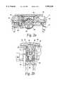
- FIG. 2Ais a cross-sectional front view of a portion of the infusion pump of FIG. 1 with the cassette disposed therein;
- FIG. 2Bis a cross-sectional side view of a portion of the infusion pump of FIG. 1 with the cassette disposed therein;
- FIG. 3Ais a cross-sectional front view of a portion of the infusion pump of FIG. 1 with a second type of cassette disposed therein;
- FIG. 3Bis a cross-sectional side view of a portion of the infusion pump of FIG. 1 with the second type of cassette disposed therein;
- FIG. 4Ais a cross-sectional side view of the first type of cassette in which a flexible tube is clamped
- FIG. 4Bis a top view of the cassette of FIG. 4A;
- FIG. 5Ais a front elevational view of a platen which forms part of the cassette of FIG. 4A;
- FIG. 5Bis a side elevational view of the platen of FIG. 5A;
- FIG. 6is cross-sectional side view of a portion of the infusion pump
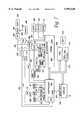
- FIG. 7is a block diagram of the electronic components of the infusion pump of FIG. 1;
- FIGS. 8A-8Cillustrate various embodiments of the cassette sensor shown schematically in FIG. 7;
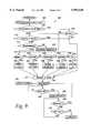
- FIG. 9is a flowchart of the overall operation of the infusion pump.
- FIG. 10is a flowchart of the ready-to-run step shown schematically in FIG. 9;
- FIG. 11is a flowchart of the operating system utilized by the infusion pump
- FIG. 12is a flowchart of a turn-off routine performed during the operation of the infusion pump
- FIGS. 13A-13Care flowcharts of three sensor routines performed during the operation of the infusion pump
- FIG. 14is a flowchart of a backlight routine performed during the operation of the infusion pump.
- FIG. 15illustrates a number of data-recording steps performed during the operation of the infusion pump.
- FIG. 1A preferred embodiment of a battery-powered, ambulatory infusion pump 10 in accordance with the invention is illustrated in FIG. 1 along with a first type of cassette 12 which is insertable into the pump 10.
- the portable pump 10may be carried in a pouch or other device (not shown) attached to a patient so that the pump 10 may be carried wherever the patient goes.
- the infusion pump 10has a keypad 14 via which a user may input data and commands, a selectively backlighted, dot matrix display 16 for displaying textual messages to the user, a light sensor 18 for detecting the level of ambient light, and a pair of light-emitting diodes (LED) 20, a green LED for indicating the normal operation of the pump 10 and a red LED for indicating an alarm or abnormal operating condition of the pump 10.
- the level of light sensed by the ambient light sensor 18is used to control when the display 16 is backlighted.
- a door 30is pivotally attached to the upper portion of the infusion pump 10 via a number of hinges 32.
- the underside of the door 30, which is shown in FIG. 1,has a pair of slots formed therein in which a pair of metal rods 35 are fixed. As described below, each of the metal rods 35 selectively engages a pair of slidable latching members to retain the door 30 in the closed position during operation of the pump 10.
- An arcuate metal leaf spring 36is disposed on the underside of the door 30.
- the two ends of the leaf spring 36are anchored by a pair of retaining elements 38 fixed to the door 30.
- the leaf spring 36makes contact with and applies a downward force on the upper surface 42 of a vertically movable platen 44.
- the upper surface 42 of the platen 44is disposed within an elongated slot or aperture 43 disposed in the upper surface of the cassette housing 12.
- the platen 44has a lower curved surface 46 against which the flexible tube 40 is pressed by a number of rollers 48 disposed on a conventional rotary pump wheel 49 (see FIG. 2A) to facilitate pumping of liquid through the tube 40.
- the rotary pump wheel 49is fixed to a gear 50 (FIG. 2B) which is driven by a drive belt (not shown) connected to a DC motor 51 (FIG. 7) via a gear drive assembly (not shown).
- Liquidis supplied to the tube 40 via a supply tube 52 connected to a source of liquid, which may be a liquid supply container or bag (not shown) fixed to the housing of the pump 10.
- the liquidis infused into the patient via a catheter or other injection device (not shown) fluidly connected to a length of tubing 54 fluidly connected to the tube 40.
- the tubing 52, 54may comprise conventional polyvinylchloride (PVC) tubing having an outside diameter slightly larger than the inside diameter of the flexible tube 40 so that the tubing 52, 54 may be inserted into the flexible tube 40 to effect a liquid-tight seal.
- PVCpolyvinylchloride
- the tubing 52, 54may be solvent-bonded to the cassette housing 12, which is plastic, to prevent the tubing 52, 54 from being inadvertently pulled from the tube 40.
- the bottom portion of the cassette 12has two semi-circular retaining members 56 integrally formed therewith, each of which abuts a portion of the flexible tube 40 where it overlaps the tubing 52, 54 to further prevent the tubing 52, 54 from being inadvertently pulled from the tube 40.
- a second pair of similar semi-circular retaining membersare integrally formed with the pump housing at a point directly below the retaining members 56, as shown in FIGS. 2A and 3A, for the same purpose.
- the cassette 12has a flow-stop mechanism 60 that automatically clamps the flexible tube 40 shut when the cassette 12 is not disposed in the pump 10 or when the pump door 30 is open.
- the flow-stop mechanism 60which is shown in detail in FIGS. 2A and 2B, has a housing 62 in which a vertically displaceable flow-stop member 64 and a spring 66 are disposed. As shown in FIG. 2B, the flexible tube 40 passes through a slot 68 formed in the flow-stop member 64, and the spring 66 biases the flow-stop member 64 upwardly.
- one of the spring retaining members 38makes contact with an upper surface 70 of the flow-stop member 64, thus preventing the spring 66 from forcing the flow-stop member 64 upwards enough to cause the flexible tube 40 to be flattened by the bottom surface of the slot 68.
- the spring 66forces the flow-stop member 64 upwards a distance sufficient to flatten the flexible tube 40, as shown in FIG. 4A, so as to prevent any liquid flow therethrough.
- the flow-stop mechanism 60may be disabled by manually aligning a bore 74 (FIG. 2B) in the flow-stop housing 62 with a bore 76 in the flow-stop member 64 and inserting a pin 78 (see FIG. 1) into the aligned bores 74, 76.
- the pin 78When placed in the bores 74, 76, the pin 78 will prevent the flow-stop member 64 from being displaced upwardly by the spring 66, and thus prevent the flexible tube 44 from being flattened and the liquid flow from being cut off.
- FIGS. 3A and 3Billustrate a second type of cassette, which is shown disposed within the infusion pump 10.
- the only difference between the two types of cassettes 12is the size and shape of the bottom portion of the flow-stop member 64.
- the bottom portion of the flow-stop member 64 of the first type of cassette 12, shown in FIGS. 2A and 2B,is generally spherical and does not extend outside of the flow-stop housing 62.
- the bottom portion of the flow-stop member 64 of the second type of cassette 12, shown in FIGS. 3A and 3Bhas a downwardly angled finger 82 that extends through a circular bore 84 disposed in the bottom of the flow-stop housing 62.
- the cassette 12has a length L of approximately 9.7 centimeters (cm), a height H of approximately 1.5 cm, and a width W of approximately 0.8 cm.
- the outer diameter of the flexible tube 40 (when undistorted)is approximately 0.4 cm.
- the upper surface 42 of the platen 44which is shown in FIGS. 4A and 4B, has an elongated central aperture 86 formed therein and is slightly curved to generally conform to the arcuate shape of the leaf spring 36.
- the platen 44has a bottom portion 90 and a top portion 92, the bottom portion 90 being wider than the top portion 92.
- the top portion 92 of the platen 44is loosely disposed within the slot 43 (FIG. 4B) formed in the cassette 12 and is retained in the slot 43 only by the presence of the flexible tube 40 beneath the bottom of the platen 44, as shown in FIG. 4A.
- the infusion pump 10has a latching mechanism 100, illustrated in FIG. 6, for retaining the door 30 in its closed position.
- the latching mechanism 100includes a pair of horizontally slidable metal plates 102a, 102b which are supported by a flat portion of a rotary pump wheel housing 104 and a pair of support beams 106.
- Each of the metal plates 102a, 102bhas a respective pair of curved latch members 108a, 108b integrally formed therewith.
- a pair of independently operable door-release buttons 110a, 110bare disposed on either side of the infusion pump 10.
- Each door-release button 110a, 110bhas a hollow cylindrical body portion 112a, 112b and a central member 114a, 114b disposed within the hollow body portion 112a, 112b.
- Each of the central members 114a, 114bengages a respective end of one of the slidable plates 102a, 102b.
- a pair of annular slots 116a, 116bare formed in the body portions 112a, 112b, and a pair of ridges 118a, 118b integrally formed with the pump housing are disposed within the slots 116a, 116b to limit the horizontal displacement of the door-release buttons 110a, 110b.
- Each of the slidable plates 102a, 102bhas a respective central aperture 120a, 120b disposed therein, and a spring 122 is disposed within both the of central apertures 120a, 120b so as to spring-bias or force each of the slidable plates 102a, 102b against the central member 114a, 114b of the door-release button 110a, 110b with which the end of the slidable plate 102a, 102b makes contact.
- the spring 122may be retained within the apertures 120a, 120b by an L-shaped retaining member (not shown).
- the two curved latches 108a, 108b of each of the plates 102a, 102bengage both of the rods 35 fixed to the underside of the pump door 30, due to the force of the spring 122, thus preventing the door 30 from being opened.
- Each plate 102a, 102b aloneis sufficient to keep the door 30 closed.
- both of the door-release buttons 110a, 110bmust be simultaneously depressed, in which case the slidable plates 102a, 102b are moved, against the force of the spring 122, to cause the curved latches 108a, 108b to disengage the metal rods 35, thus allowing the door 30 to be opened.
- the door 30may be provided with a spring or other means (not shown) to cause the door 30 to open automatically when both of the door-release buttons 110a, 110b are pressed. Since both of the door-release buttons 110a, 110b must be actuated to open the door 30, any inadvertent opening of the door 30 due to the infusion pump 10 being dropped or Jarred is reduced or eliminated.
- the infusion pump 10includes a controller 200 with a built-in analog-to-digital (A/D) converter 200a, an electrically programmable read-only memory (EPROM) 204 having a built-in input/output (I/O) interface 204a, a random-access memory (RAM) 208, a real-time clock 210 and the display 16, all of which are interconnected by a communications bus 212.
- the display 16has a backlight 220 which is selectively activated by an enable signal generated on a line 222 interconnecting the controller 200 and the backlight 220.
- Both the RAM 208 and the real-time clock 210are connected to a battery 214 which supplies power to them only in the absence of system power (generated by a second battery 282). Since it is always powered, the RAM 208 is a non-volatile memory.
- the controller 200which may be a conventional microcontroller such as an 80C196KB commercially available from Intel Corporation, controls an audible alarm generator 230 via a line 232, the LEDs 20 via a line 234, and an amplifier circuit 236 via a line 238.
- the amplifier circuit 236is connected to drive the pump motor 51 which drives the rotary pump wheel 49.
- the controller 200also sends a periodic signal to a conventional watchdog timer 250 via a line 252.
- the watchdog timer 250transmits a signal via a line 260 to cause the alarm 230 to sound, transmits a signal via a line 262 to cause the red LED to be illuminated, and transmits a signal via a line 264 to the amplifier circuit 236 to cause the pump motor 51 to stop.
- the pump 10has a number of sensors which sense various conditions relating to the operation of the pump. These sensors include an input pressure sensor 270 for detecting the liquid pressure within the flexible tube 40 at a point upstream of the rotary pump wheel 49 and an output pressure sensor 272 for detecting the liquid pressure within the flexible tube 40 at a point downstream of the rotary pump wheel 49.
- the input pressure sensor 270generates an analog signal, indicative of the input pressure, which is transmitted to the A/D converter 200a via a line 274, and the output pressure sensor 272 generates an analog signal, indicative of the output pressure, which is transmitted to the A/D converter 200a via a line 276.
- Each of the pressure sensors 270, 272, which detect occlusions with the flexible tube 40 or the tubing 52, 54 connected thereto,may be provided in the form of a strain gauge or beam (not shown) which is in contact with the exterior of the flexible tube 40 and a high-gain amplifier (not shown) connected to the strain beam.
- the pressure sensors 270, 272are connected to and receive power from a power switch 280 which is connected to a battery 282 through a system power switch 284, a voltage regulator 286, and a system power line 287.
- the system power switch 284selectively supplies power from the battery 282 to the voltage regulator 286 based on the state of a pump on/off switch 288 connected to the system power switch 284.
- the power switch 280is controlled by the controller 200 via the bus 212, the I/O interface 204a, and a line 294 which interconnects the I/O interface 204a and the power switch 280.
- the pump 10has an air-in-line sensor 300, which may be provided in the form of a conventional piezoelectric transmitter and receiver (not shown) coupled to a sensing circuit (not shown), to detect the presence of any significant air bubbles within the flexible tube 40.
- the air-in-line sensor 300receives power from a power switch 302 which is connected to the system power line 287 and controlled by the controller 200 via a line 304 connected to the I/O interface 204a.
- the pump 10has a shaft encoder sensor 308 and a Hall-effect sensor 310 which receive power from a power switch 312 coupled to the system power line 287 and controlled by the controller 200 via a line 314.
- the shaft encoder sensor 308, which is disposed on the shaft of the motor 51,may be a two-phase motion sensing encoder which provides two signal outputs to the controller 200.
- the rotational speed of the motor 51 and its direction of rotationare determined by the controller 200 based upon the rate and phase relationship between the two signal outputs.
- the Hall-effect sensor 310is disposed adjacent the rotary pump wheel 49 and detects magnetic encoding on the pump wheel 49 for detecting rotation of the wheel 49.
- a cassette sensor 320which is also connected to the power switch 312, detects the type of cassette which is inserted into the pump 10. As described below, the pump 10 may accept different types of cassettes and take different operating actions based upon the type of cassette which is inserted.
- FIGS. 8A-8CVarious possible embodiments of the cassette sensor 320 are shown in FIGS. 8A-8C. Each embodiment includes a force-sensitive resistive element 322 disposed in a sensing circuit.
- the circuits of FIGS. 8A and 8Bact as force-to-voltage converters (the amplifier 323 in FIG. 8B is an operational amplifier), and the circuit of FIG. 8C (which includes a Schmidtt trigger 324) acts as a force-to-frequency converter.
- the forceis generated by the physical contact between the downwardly angled finger 82 of the second type of cassette 12 shown in FIGS. 3A and 3B and the force-sensitive resistive element 322 when the cassette 12 is inserted into the pump 12 and the door 30 is closed. Since the first type of cassette 12 shown in FIGS. 2A and 2B has no downwardly extending finger, the insertion of that type of cassette does not result in any physical contact with the force-sensitive resistive element 322. Thus, the resistance of the resistive element 322 changes only when the second type of cassette 12 is inserted, thus causing the cassette sensor 320 to generate an electrical signal (a voltage signal in the cases of FIGS. 8A and 8B and a frequency signal in the case of FIG.
- the force-sensitive resistive element 322is a conventional component which is commercially available from Interlink Electronics of Carpinteria, Calif. As described below, other types of sensors may be utilized.
- the ambient light sensor 18is connected to a power switch 326 which is controlled by the controller 200 via a line 328 from the I/O interface 204a. Signals generated by a door-open sensor 330, a bolus infusion request switch 332, and the keypad 14 are transmitted to the controller 200 via the I/O interface 204a.
- the controller 200, the EPROM 204, the RAM 208 and the display 16are also connected to and receive power from the system power line 287.
- the operation of the infusion pump 10is controlled by a computer program stored in the EPROM 204 and executed by the controller 200.
- a flowchart of the overall operationis illustrated in FIG. 9. Referring to FIG. 9, when the pump 10 is turned on via the on/off switch 288, at step 402 the pump is initialized and a test of the pump operation is performed. The pump 10 may be turned off temporarily during an infusion, in which case the pump 10 may continue the infusion when it is turned back on, as described below.
- step 404if there is any remaining volume of liquid to be infused by the pump or any additional time remaining for an infusion, which would be the case where the pump was temporarily turned off during an infusion, the program branches to step 406, where the user is asked, via a message displayed on the display 16, whether the previous infusion should be resumed. If the user answers yes (via the keyboard 14), the program branches to a ready-to-run step 410. If the previous infusion is not to be resumed, the program branches to step 412.
- the infusion pump 10has a lockout mode in which the user may be prevented from programming the infusion parameters, such as the volume to be infused or the rate of infusion.
- the pump 10could be programmed by a medical assistant to deliver a particular infusion having a particular flow profile, flow rate and volume to be infused. After programming that infusion, the medical assistant could place the pump in lockout mode, which would prevent the patient from changing any of the infusion parameters.
- the programbranches directly to the ready-to-run step 410, bypassing all programming steps.
- step 412if the pump is not in lockout mode, the program branches to step 414, at which point the program prompts the user, via the display 16, to input whether the patient should be allowed to program the pump during the subsequent infusion. If the pump is not to be programmable, the program branches to step 416 where a lockout sequence is performed by requesting the user to input which infusion modes should be locked out. If the pump is to be programmable by the patient, the program bypasses step 416.
- the infusion pump 10has five basic modes of infusion: 1) a continuous mode in which the pump delivers a single volume at a single rate; 2) an auto-ramp mode in which the pump delivers liquid at a rate that gradually increases to a threshold rate, stays constant at the threshold rate, and then gradually decreases; 3) an intermittent mode in which the pump delivers discrete liquid volumes spaced over relatively long periods of time, such as a liquid volume every three hours; 4) a custom mode in which the pump can be programmed to deliver a unique infusion rate during each of 25 different time periods; and 5) a pain-controlled analgesic (PCA) mode during which the pump will periodically infuse boluses of analgesic in response to periodic requests by the patient, which requests are made via the bolus-request key 332.
- PCApain-controlled analgesic
- the pump 10generates on the display 16 the prompt "Continuous?" to the user. If the user desires to use the pump in its continuous mode, the user answers "yes" via the keypad 14, and the program branches to step 420 at which the continuous mode is programmed by the user by entering a number of infusion parameters, such as the desired infusion rate, the volume to be infused, etc. At step 418, if the user does not want to use the continuous mode, the user answers "No," and the program branches to step 422. Steps 422-436 are generally the same as steps 418 and 420, except that the user may be prompted for different infusion parameters, depending on which of the five possible infusion modes is selected.
- the programbranches to the ready-to-run step 410, a flowchart of which is shown in FIG. 10.
- the ready-to-run step 410includes a step 440 at which the infusion rate and the volume to be infused which were entered during one of the programming steps 420, 424, 428, 432, 436, are shown on the display 16. Then the program waits at step 442 until the "Run" key of the keypad 14 is pressed, at which point the program branches to step 444 where the cassette sensor 320 is checked to determine which type of cassette has been inserted into the infusion pump 10.
- the infusion pump 10has the capability to alter its operation based upon the type of cassette 12 which is inserted into the pump 10, as determined by the cassette sensor 320.
- the insertion of the cassette 12 shown in FIGS. 3A-3Bwhich is referred to herein as a "micro-set," prevents the infusion pump 10 from performing an infusion if the programmed infusion rate exceeds a predetermined limit.
- the programbranches to step 448 where the infusion rate parameters entered during one of the programming steps 420-436 are checked.
- step 450if the programmed infusion rate exceeds the predetermined limit, which may be 99.9 milliliters/hour, the program branches to step 452 where the pump generates a message on the display 16 to that effect and branches back to step 440 upon any key being pressed at step 454. If a micro-set was not installed as determined at step 446, the program skips steps 448-454 and branches directly to the run mode 460 shown in FIG. 9.
- the predetermined limitwhich may be 99.9 milliliters/hour
- the pump 10infuses the patient with a liquid medicant in accordance with the infusion mode selected at one of steps 418, 422, 426, 430, 434 and the infusion parameters entered at one of steps 420, 424, 428, 432, 436.
- the pump 10remains in the run mode 460 until the hold key is pressed, as determined at step 462.
- an alarmis reported at step 464.
- step 462if the hold key is pressed, the infusion is stopped at step 466, and the pump 10 waits for the run key to be pressed at step 468 or the on/off switch to be turned off at step 470.
- a medical assistantturns the pump on, programs the desired infusion mode at one of steps 420, 424, 428, 432, 436, and then turns the pump off.
- the programmed infusion parameterswill be retained in the nonvolatile memory 208.
- the medical assistantwould then turn the pump back on, press the "No" key in response to the "Programmable?" prompt at step 414, enter the lockout information at step 416, and then turn the pump off again.
- the programwould proceed from step 412 directly to the ready-to-run step 410, which would prevent the patient from altering the infusion parameters.
- the medical assistant or the patientcould turn the pump on, program the desired infusion mode, and then press the "Run” key to start the infusion without ever turning the pump off.
- the ability of the pump to take different actions based upon the type of cassette inserted into the pumpcould be utilized in many ways.
- the pumpcould be utilized with any of four different types of cassettes, and the pump could be preprogrammed with a unique infusion mode and/or a unique set of infusion parameters for each type of cassette.
- the different infusion modescould be based on the liquid medicant to be infused.
- These liquid medicantswould be used with a type of cassette that, when inserted into the pump, would cause the pump to automatically set the infusion mode to the auto-ramp mode.
- the program illustrated in FIG. 9would branch from step 414 directly to step 424 without any intervening programming steps.
- the continuous mode of infusionmay be appropriate.
- the infusion parameters entered at one of steps 420, 424, 428, 432, 436could also be customized based upon the type of cassette inserted and/or the liquid medicant to be infused.
- cassettescould be distinguished by the pump 10 based upon the length (or flexibility) of the flow-stop member (which could have four slightly different lengths or flexibilities), so that four distinct forces would be generated on the force-sensitive resistive element 322, or in a conventional manner based upon other structural features of the cassette.
- two light detectorscould be disposed side by side in the top portion of the pump, each light detector having a transmitter which transmits a light beam to an associated receiver.
- Each cassettecould be uniquely identified by the presence (or absence) of two notches, each notch being positioned adjacent one of the light detectors.
- Each light detectorwould detect the presence of a notch because the light beam would be uninterrupted when the cassette was inserted into the pump, whereas the absence of a notch would cause the light beam to be interrupted upon insertion of the cassette.
- the use of two light detectors and two associated notch locationswould allow detection of four different types of cassettes, thus allowing four pre-programmed modes of pump operation.
- FIG. 11A flowchart of the operating system 500 of the infusion pump 10 is illustrated in FIG. 11.
- the operating system 500determines how the operations and tasks shown in the flowchart of FIG. 9 are performed.
- the pumpmay operate in a sleep mode which utilizes a relatively low rate of power consumption from the battery 282, such as 50 microamperes.
- the controller 200When in the sleep mode, the controller 200 does not execute any instructions of the computer program, and its internal clocks are turned off.
- the pumpis periodically placed in an idle mode which utilizes an intermediate rate of power consumption, such as 8 milliamperes.
- the controller 200When the pump is in the idle mode, the controller 200 does not execute any instructions of the computer program, but its internal clocks continue to run. If the pump is in neither the sleep mode nor the idle mode, the computer program is executed and the internal clocks in the controller 200 run. In this operating mode, power is consumed at a relatively high rate, such as 17 milliamperes.
- step 504if the pump is not operating in the run mode 460 as determined at step 502, the program branches to step 504 where any of the processing tasks of steps 402-436 of FIG. 9 may be performed. As described above, these tasks relate to the initial programming of the infusion pump 10 and are user-interactive. When there are no more of such tasks to be performed, for example, where the user has paused during the programming of the pump or has completed the pump programming, the program branches to step 506, where the controller 200 is placed in its idle mode, described above, via a software command. The controller 200 exits the idle mode upon the generation of an interrupt that is generated at step 508. The interrupt is periodically generated by the controller 200, for example, every 20 milliseconds.
- the programcycles through steps 502-508 where it alternately performs at step 504 one or more of the processing tasks shown at steps 402-436 in FIG. 9 and is idled at step 506 to conserve battery power.
- the pumpmay operate in the sleep mode described above.
- the pumpmay operate in the sleep mode when it is in the run mode 460 (FIG. 9) and is pumping below a relatively low infusion rate threshold, such as five milliliters/hour.
- the motor 51is not activated continuously, but is instead turned on periodically (the motor 51 has a minimum rate at which it must be driven or else it will stall) to deliver a relatively small volume of liquid medicant, 50 microliters for example, and then is turned off. It is when the motor 51 is turned off when the controller 200 is placed in the sleep mode.
- the programmed infusion rateis below the threshold, the frequency with which the motor turns on and off is determined by the programmed infusion rate. If the programmed infusion rate is above the threshold, the motor 51 will pump continuously.
- step 510if the pump is not in a stealth mode (described below), the program branches to step 512 where a number of processing tasks relating to the infusion may be performed.
- step 514the watchdog timer 250 is strobed, and at step 516 the program determines whether the controller 200 may be placed in the sleep mode. As described above, the controller 200 may be placed in the sleep mode if the infusion rate is less than a predetermined threshold rate. There are also other conditions which must be satisfied.
- the motor 51cannot be active, an audio beep (in response to a key being pressed for example) cannot be active, no timed functions can be active (such as a timed LED illumination), the backlight 220 cannot be on, and the display 16 cannot be scrolling text. If these conditions are satisfied, the program branches to step 520 where the power to a number of sensors is turned off, and to step 522 where the controller 200 is placed in its sleep mode.
- the controller 200remains in the sleep mode until it is "awakened” by any of three occurrences: 1) any key being pressed, including the bolus-request key 332; 2) the watchdog timer timing out; or 3) a one-second strobe generated by the real-time clock 210. In the absence of conditions 1) and 2), the controller 200 will be awakened every second by the strobe from the real-time clock 210. Upon being awakened, the internal clocks of the controller 200 are started at step 524, and the program branches to step 508 where it waits for the next 20 ms interrupt generated by the controller 200.
- the infusion pump 10also has a stealth mode relating to the intermittent infusion mode of FIG. 9. In this mode, the pump 10 delivers an infusion spaced at relatively large time intervals, such as minutes or hours. Between infusions, the pump is placed in a stealth mode in which the controller 200 is put to sleep.
- FIG. 12illustrates an off-control routine 530 that is periodically invoked to determine whether the on/off switch 288 (FIG. 7) of the infusion pump 10 has been turned off.
- the programbranches to step 534 where it determines if it is okay to turn the pump off (it is okay to turn the pump off as long as it is not in the run mode 460). If it is okay to turn the power off, the program branches to step 536. If the pump is not in the intermittent mode as determined at step 536, the power is turned off. If the pump is in the intermittent mode, the program branches to step 538, which determines whether there are any more periodic doses (infusions) to be made. If there are no more doses, the power is turned off.
- step 540the pump is placed in the stealth mode at step 540.
- step 550determines whether the next dose in the intermittent mode is scheduled within the next 30 minutes. If not, the program branches to steps 520-522 where the controller 200 is put to sleep.
- step 550the program branches to step 552, where it determines whether the time until the next dose, or the time after that dose if not given, is a multiple of ten minutes. If it is, then the program branches to step 554, where the pump 10 generates an audible beep to the user as a reminder that the next dose is a multiple of ten minutes away.
- the patientis given three audible warnings that the next dose is imminent, a first warning at 30 minutes prior to the dose, a second warning at 20 minutes prior to the dose, and a third warning at 10 minutes prior to the dose. If the next dose is not given on schedule, a fourth warning is generated at the time of the dose, and three additional warnings, spaced 10 minutes apart, are given after the time for the dose.
- a number of the sensors used to sense various conditionsmay be turned on only when they are active in order to conserve battery power.
- the sensors that are selectively turned oninclude the input pressure sensor 270, the output pressure sensor 272, the air-in-line detector 300, the shaft encoder 308, the Hall-effect sensor 310 and the ambient light sensor 18. These powering of these sensors is controlled by a number of computer program routines, three of which are illustrated in FIGS. 13A-13C.
- a pressure sensor routine 600may be used for the selective powering of the input and output pressure sensors 270, 272. If it is time to check either the input pressure or the output pressure in the flexible tube 40 as determined at step 602, the power supplied to both pressure sensors 270, 272 is turned on at step 604 via the line 294 to the power switch 280. The program then delays (e.g. a delay of 20 ms) at step 606 to allow the sensors 270, 272 to stabilize, and then the sensed pressure is read at step 608, following which both sensors 270, 272 are turned off at step 610 via the control line 294 to the power switch 280.
- delayse.g. a delay of 20 ms
- a sensor routine 620may be used for the selective powering of the shaft encoder 308 of the motor 51.
- the shaft encoder 308is active only when the motor 51 is turning, as determined at step 622. If it is time to turn the motor 51, the power supplied to the shaft encoder 308 is turned on at step 624 via the control line 314 to the power switch 312. The program then delays at step 626 to allow the shaft encoder 308 time to stabilize, after which time the shaft encoder 308 will automatically generate signals indicative of the rotational rate and direction of the motor shaft. When the motor stops turning, as determined at step 628, the power to the shaft encoder 308 is turned off at step 630 via the control line 314 to the power switch 312.
- a sensor routine 640may be used for the selective powering of the air-in-line sensor 300. If it is time to check the air-in-line sensor 300 as determined at step 642, the power supplied to the air-in-line sensor 300 is turned on at step 644 via the line 304 to the power switch 302. The program then delays (e.g. a delay of 2 ms) at step 646 to allow the sensor 300 to stabilize, and then the sensor 300 is read at step 648, following which the sensor 300 is turned off at step 650 via the control line 304 to the power switch 302. The routines shown in FIG. 13B and 13C may be performed only when the criteria for the sleep mode are satisfied as described above in connection with step 516.
- the infusion pump 10incorporates another power-saving feature in that the backlight 220 for the display 16 is activated only under certain conditions. If either a key on the keypad 14 is pressed or a visual alarm message is generated on the display 16, the routine 700 causes the backlight 220 to be activated, via the control line 222, when the ambient light fails to surpass a predetermined threshold, as detected by the ambient light sensor 18.
- step 704the ambient light sensor 18 is read (after the sensor 18 is powered up via the control line 328 connected to the power switch 326). If the amount of ambient light detected by the sensor 18 does not surpass a predetermined light threshold as determined at step 706, then the backlight 220 is turned on at step 708 via the control line 222 connected to the backlight 220.
- a backlight timerwhich causes the backlight 220 to be turned on only for a predetermined period of time, is then reset.
- step 702If no alarm was present as determined at step 702, then the program branches to step 712 which determines whether a key has been pressed. If so, then the program performs steps 704-710 to turn on the backlight 220 if the ambient light does not surpass a threshold level, as described above.
- Steps 714-720cause the backlight 220 to be automatically turned off after a predetermined period of time as determined by the backlight timer.
- the programbranches to step 716 where the backlight timer is incremented (the routine 700 is performed periodically, such as every 20 milliseconds).
- the programbranches to step 720 where the backlight 220 is turned off.
- the infusion pump 10automatically records in the non-volatile memory 208 all significant infusion data to generate a complete historical data record which can be later retrieved from the memory 208 and used for various purposes, including clinical purposes to aid in determining how effective a particular infusion therapy was and treatment purposes to confirm that the prescribed infusion was actually delivered.
- FIG. 15illustrates various steps at which infusion data is recorded that are performed during the overall pump operation shown generally in FIG. 9.
- the infusion data recorded in the memory 208is set forth in Table 1 below. A number of events which trigger the storage of data are listed in the left-hand column of Table 1, and the infusion data that is recorded upon the occurrence of each event is listed in the right-hand column of Table 1.
- the time at which the infusion data is recorded, which is determined by the real-time clock 210,is also stored along with the infusion data.
- the pumpalso stores any infusion rate changes, such as changes caused by switching from a continuous rate to a keep-vein-open (KVO) rate, or in the intermittent mode, changing (from a KVO rate to a higher infusion rate, the presence of which are detected at step 814.
- KVOkeep-vein-open
- the new rate and the time at which the new rate startedare stored at step 816.
- step 818if any alarms are generated, the alarm type, the time at which the alarm occurred, and the total volume infused at the time of the alarm are recorded at step 820. If the infusion is completed as determined at step 822, the program branches to step 824 where the time at which the infusion was completed is stored along with the total volume infused. At step 826, if there is a malfunction, the malfunction type, the time at which the malfunction occurred, and the total volume infused at the time of the malfunction are recorded at step 828.
- step 830if the infusion is resumed (when the pump is turned back on after having been turned off during an infusion), the time at which the infusion is resumed along with the infusion parameters are stored at step 832.
- the time at which the programming of the lockout was completedis stored along with the infusion modes that were locked out.
- the time at which the bolus was requestedis stored, along with an indication whether the bolus was actually given and the amount of the bolus.
Landscapes
- Health & Medical Sciences (AREA)
- Heart & Thoracic Surgery (AREA)
- Animal Behavior & Ethology (AREA)
- General Health & Medical Sciences (AREA)
- Biomedical Technology (AREA)
- Engineering & Computer Science (AREA)
- Hematology (AREA)
- Life Sciences & Earth Sciences (AREA)
- Veterinary Medicine (AREA)
- Anesthesiology (AREA)
- Public Health (AREA)
- Vascular Medicine (AREA)
- Emergency Medicine (AREA)
- Pulmonology (AREA)
- Infusion, Injection, And Reservoir Apparatuses (AREA)
- Reciprocating Pumps (AREA)
Abstract
Description
TABLE 1 ______________________________________ EVENT DATA RECORDED ______________________________________ Power On Date and Time Program Infusion parameters. See Table 2. Run Infusion parameters. See Table 2. Hold Total Volume Infused Restart Time of Restart Rate Changes Total Volume Infused, Rate, Volume Alarms Total Volume Infused, Alarm Type Infusion Complete Total Volume Infused Malfunctions Total Volume Infused, Malfunction Type Resume Infusion parameters. See Table 2. Maintenance Date Date Patient ID Patient ID Number Serial No. Serial Number Language Change New Language Lockout Modes Locked Out Pressure Select New Pressure Setting Bolus Request Given/Not Given, Bolus Amount Titration New Parameters Power Off Time of Power Off Version No. Software Version Number ______________________________________
TABLE 2 ______________________________________ INFUSION MODE INFUSION PARAMETERS ______________________________________ Continuous Infusion Mode Infusion Rate Volume To Be Infused Delay Time Total Bag Volume KVO Rate Auto-Ramp Infusion Mode Infusion Rate Volume To Be Infused Delay Time Total Bag Volume Duration of Up-Ramp Duration of Down-Ramp KVO Rate Intermittent Infusion Mode Total Infusion Time Number of Doses Dose Time Dose Volume KVO Rate ______________________________________
Claims (12)
Priority Applications (1)
| Application Number | Priority Date | Filing Date | Title |
|---|---|---|---|
| US09/010,918US5993420A (en) | 1995-03-06 | 1998-01-22 | Cassette for an infusion pump |
Applications Claiming Priority (2)
| Application Number | Priority Date | Filing Date | Title |
|---|---|---|---|
| US08/398,886US5904668A (en) | 1995-03-06 | 1995-03-06 | Cassette for an infusion pump |
| US09/010,918US5993420A (en) | 1995-03-06 | 1998-01-22 | Cassette for an infusion pump |
Related Parent Applications (1)
| Application Number | Title | Priority Date | Filing Date |
|---|---|---|---|
| US08/398,886ContinuationUS5904668A (en) | 1995-03-06 | 1995-03-06 | Cassette for an infusion pump |
Publications (1)
| Publication Number | Publication Date |
|---|---|
| US5993420Atrue US5993420A (en) | 1999-11-30 |
Family
ID=23577199
Family Applications (2)
| Application Number | Title | Priority Date | Filing Date |
|---|---|---|---|
| US08/398,886Expired - Fee RelatedUS5904668A (en) | 1995-03-06 | 1995-03-06 | Cassette for an infusion pump |
| US09/010,918Expired - Fee RelatedUS5993420A (en) | 1995-03-06 | 1998-01-22 | Cassette for an infusion pump |
Family Applications Before (1)
| Application Number | Title | Priority Date | Filing Date |
|---|---|---|---|
| US08/398,886Expired - Fee RelatedUS5904668A (en) | 1995-03-06 | 1995-03-06 | Cassette for an infusion pump |
Country Status (8)
| Country | Link |
|---|---|
| US (2) | US5904668A (en) |
| EP (1) | EP0813430B1 (en) |
| JP (1) | JPH11506355A (en) |
| AT (1) | ATE182799T1 (en) |
| AU (1) | AU5182696A (en) |
| DE (1) | DE69603582T2 (en) |
| ES (1) | ES2136981T3 (en) |
| WO (1) | WO1996027402A1 (en) |
Cited By (55)
| Publication number | Priority date | Publication date | Assignee | Title |
|---|---|---|---|---|
| US6527743B1 (en)* | 2000-05-03 | 2003-03-04 | Ethicon Endo-Surgery, Inc. | Surgical system pump and method therefor |
| US20030109826A1 (en)* | 2000-05-03 | 2003-06-12 | Conmed Corp. | Surgical system pump and method therefor |
| US20030236489A1 (en)* | 2002-06-21 | 2003-12-25 | Baxter International, Inc. | Method and apparatus for closed-loop flow control system |
| FR2871858A1 (en)* | 2004-06-22 | 2005-12-23 | Gilson Sas Soc Par Actions Sim | PERISTALTIC PUMP COMPRISING A LOCKABLE REMOVABLE CASSETTE |
| US6997905B2 (en) | 2002-06-14 | 2006-02-14 | Baxter International Inc. | Dual orientation display for a medical device |
| US7018361B2 (en) | 2002-06-14 | 2006-03-28 | Baxter International Inc. | Infusion pump |
| WO2006044409A2 (en) | 2004-10-13 | 2006-04-27 | Mallinckrodt Inc. | Power injection system with powerhead having a display |
| US20070217932A1 (en)* | 2004-06-22 | 2007-09-20 | Claude Voyeux | Method and system for providing adjustable compression force on a tube in a peristaltic pump |
| US7727196B2 (en) | 2004-10-13 | 2010-06-01 | Mallinckrodt Inc. | Powerhead of a power injection system |
| USD626647S1 (en) | 2009-10-13 | 2010-11-02 | Smiths Medical Asd, Inc. | Infusion pump cassette |
| US20110087165A1 (en)* | 2009-10-13 | 2011-04-14 | Chad Amborn | Two piece medication cassette closure apparatus and method |
| US7934912B2 (en) | 2007-09-27 | 2011-05-03 | Curlin Medical Inc | Peristaltic pump assembly with cassette and mounting pin arrangement |
| US8062008B2 (en) | 2007-09-27 | 2011-11-22 | Curlin Medical Inc. | Peristaltic pump and removable cassette therefor |
| US8083503B2 (en) | 2007-09-27 | 2011-12-27 | Curlin Medical Inc. | Peristaltic pump assembly and regulator therefor |
| US8105269B2 (en) | 2008-10-24 | 2012-01-31 | Baxter International Inc. | In situ tubing measurements for infusion pumps |
| US8137083B2 (en) | 2009-03-11 | 2012-03-20 | Baxter International Inc. | Infusion pump actuators, system and method for controlling medical fluid flowrate |
| US8234128B2 (en) | 2002-04-30 | 2012-07-31 | Baxter International, Inc. | System and method for verifying medical device operational parameters |
| US8323492B2 (en) | 2007-10-24 | 2012-12-04 | Baxter International Inc. | Hemodialysis system having clamping mechanism for peristaltic pumping |
| US8382447B2 (en) | 2009-12-31 | 2013-02-26 | Baxter International, Inc. | Shuttle pump with controlled geometry |
| US8567235B2 (en) | 2010-06-29 | 2013-10-29 | Baxter International Inc. | Tube measurement technique using linear actuator and pressure sensor |
| US8775196B2 (en) | 2002-01-29 | 2014-07-08 | Baxter International Inc. | System and method for notification and escalation of medical data |
| US8974415B2 (en) | 2012-04-10 | 2015-03-10 | Smiths Medical Asd, Inc. | Flow stop insert apparatus and methods |
| US9381288B2 (en) | 2013-03-13 | 2016-07-05 | Thoratec Corporation | Fluid handling system |
| US9662437B2 (en) | 2014-04-28 | 2017-05-30 | Smiths Medical Asd, Inc. | Infusion pump pressure plate |
| US9770554B2 (en) | 2011-09-13 | 2017-09-26 | Quest Medical, Inc. | Cardioplegia apparatus and method |
| US10016554B2 (en) | 2008-07-09 | 2018-07-10 | Baxter International Inc. | Dialysis system including wireless patient data |
| US10061899B2 (en) | 2008-07-09 | 2018-08-28 | Baxter International Inc. | Home therapy machine |
| US10071192B2 (en) | 2013-03-15 | 2018-09-11 | Tc1 Llp | Catheter pump assembly including a stator |
| US10173008B2 (en) | 2002-01-29 | 2019-01-08 | Baxter International Inc. | System and method for communicating with a dialysis machine through a network |
| US20190099552A1 (en)* | 2014-08-28 | 2019-04-04 | Zyno Medical, Llc | Low-Cost Ambulatory Medical Pump |
| US10347374B2 (en) | 2008-10-13 | 2019-07-09 | Baxter Corporation Englewood | Medication preparation system |
| US10449279B2 (en) | 2014-08-18 | 2019-10-22 | Tc1 Llc | Guide features for percutaneous catheter pump |
| US10525178B2 (en) | 2013-03-15 | 2020-01-07 | Tc1 Llc | Catheter pump assembly including a stator |
| US10646405B2 (en) | 2012-10-26 | 2020-05-12 | Baxter Corporation Englewood | Work station for medical dose preparation system |
| US10709830B2 (en) | 2015-01-22 | 2020-07-14 | Tc1 Llc | Reduced rotational mass motor assembly for catheter pump |
| US10765789B2 (en) | 2012-05-14 | 2020-09-08 | Tc1 Llc | Impeller for catheter pump |
| US10818387B2 (en) | 2014-12-05 | 2020-10-27 | Baxter Corporation Englewood | Dose preparation data analytics |
| US10864308B2 (en) | 2014-04-15 | 2020-12-15 | Tc1 Llc | Sensors for catheter pumps |
| US10960116B2 (en) | 2011-01-06 | 2021-03-30 | Tci Llc | Percutaneous heart pump |
| US10971257B2 (en) | 2012-10-26 | 2021-04-06 | Baxter Corporation Englewood | Image acquisition for medical dose preparation system |
| US11033728B2 (en) | 2013-03-13 | 2021-06-15 | Tc1 Llc | Fluid handling system |
| US11058865B2 (en) | 2012-07-03 | 2021-07-13 | Tc1 Llc | Catheter pump |
| US11107574B2 (en) | 2014-09-30 | 2021-08-31 | Baxter Corporation Englewood | Management of medication preparation with formulary management |
| US11160970B2 (en) | 2016-07-21 | 2021-11-02 | Tc1 Llc | Fluid seals for catheter pump motor assembly |
| WO2021236608A1 (en)* | 2020-05-20 | 2021-11-25 | Zyno Medical, Llc | Ambulatory medical pump cartridge locking system |
| US11229786B2 (en) | 2012-05-14 | 2022-01-25 | Tc1 Llc | Impeller for catheter pump |
| US11367533B2 (en) | 2014-06-30 | 2022-06-21 | Baxter Corporation Englewood | Managed medical information exchange |
| US11495334B2 (en) | 2015-06-25 | 2022-11-08 | Gambro Lundia Ab | Medical device system and method having a distributed database |
| US11491322B2 (en) | 2016-07-21 | 2022-11-08 | Tc1 Llc | Gas-filled chamber for catheter pump motor assembly |
| US11516183B2 (en) | 2016-12-21 | 2022-11-29 | Gambro Lundia Ab | Medical device system including information technology infrastructure having secure cluster domain supporting external domain |
| US11575673B2 (en) | 2014-09-30 | 2023-02-07 | Baxter Corporation Englewood | Central user management in a distributed healthcare information management system |
| US11692540B2 (en) | 2017-11-08 | 2023-07-04 | Oina Vv Ab | Peristaltic pump |
| US11948112B2 (en) | 2015-03-03 | 2024-04-02 | Baxter Corporation Engelwood | Pharmacy workflow management with integrated alerts |
| US12404858B2 (en) | 2006-03-23 | 2025-09-02 | The Penn State Research Foundation | Catheter blood pump heart assist device |
| US12412644B2 (en) | 2014-10-24 | 2025-09-09 | Baxter Corporation Englewood | Automated exchange of healthcare information for fulfillment of medication doses |
Families Citing this family (61)
| Publication number | Priority date | Publication date | Assignee | Title |
|---|---|---|---|---|
| US5928196A (en)* | 1996-08-14 | 1999-07-27 | Sims Deltec, Inc. | Control module cassette locks and methods |
| US5954485A (en)* | 1996-08-14 | 1999-09-21 | Sims Deltec, Inc. | Free-flow protection devices and methods |
| US5788671A (en)* | 1996-08-14 | 1998-08-04 | Sims Deltec, Inc. | Reusable cassette housings and methods |
| US5879144A (en)* | 1996-08-14 | 1999-03-09 | Sims Deltec, Inc. | Pressure plate adaptors and methods |
| US5823746A (en)* | 1996-08-14 | 1998-10-20 | Sims Deltec, Inc. | Reusable pressure plates and methods |
| US6056522A (en)* | 1998-05-13 | 2000-05-02 | Sims Deltec, Inc. | Reusable cassette with a moveable door |
| JP3423633B2 (en)* | 1998-07-02 | 2003-07-07 | 株式会社ジェイ・エム・エス | Infusion pump device |
| US6942473B2 (en) | 2002-03-21 | 2005-09-13 | Hospira, Inc. | Pump and tube set thereof |
| JP4405737B2 (en)* | 2003-02-03 | 2010-01-27 | テルモ株式会社 | Syringe pump |
| DE112004000569T5 (en)* | 2003-03-31 | 2006-03-16 | Top Corp. | Infusion pump device |
| DE10348653A1 (en)* | 2003-10-15 | 2005-05-25 | Applica Gmbh | loading device |
| US8308691B2 (en) | 2006-11-03 | 2012-11-13 | B. Braun Melsungen Ag | Catheter assembly and components thereof |
| US8231578B2 (en)* | 2007-02-28 | 2012-07-31 | Hospira, Inc. | System and method for sequencing channels in a multi-channel infusion pump |
| US9026370B2 (en) | 2007-12-18 | 2015-05-05 | Hospira, Inc. | User interface improvements for medical devices |
| US9078964B2 (en)* | 2008-08-21 | 2015-07-14 | Sur-Real Industries, Inc. | Pump device, tube device and method for movement and collection of fluid |
| WO2010088144A1 (en) | 2009-01-30 | 2010-08-05 | Nestec S.A. | Infusion pump cassette with ant i -free -flow valve mechanism |
| SG172934A1 (en)* | 2009-01-30 | 2011-08-29 | Nestec Sa | Infusion pump cassette with ant i -free -flow valve mechanism |
| RU2011135944A (en)* | 2009-01-30 | 2013-03-10 | Нестек С.А. | CARTRIDGE FOR INFUSION PUMP CONTAINING VALVE MECHANISM PREVENTING FREE FLOW |
| ES2631453T3 (en) | 2009-08-31 | 2017-08-31 | Nestec S.A. | Cassette with infusion set containing a spring-free anti-flow mechanism for a peristaltic infusion pump |
| US9192711B2 (en)* | 2010-09-24 | 2015-11-24 | Carefusion 303, Inc. | Modular infusion system |
| JP2012205866A (en)* | 2011-03-30 | 2012-10-25 | Terumo Corp | Infusion pump |
| AU2012299169B2 (en) | 2011-08-19 | 2017-08-24 | Icu Medical, Inc. | Systems and methods for a graphical interface including a graphical representation of medical data |
| US10022498B2 (en) | 2011-12-16 | 2018-07-17 | Icu Medical, Inc. | System for monitoring and delivering medication to a patient and method of using the same to minimize the risks associated with automated therapy |
| US11295846B2 (en)* | 2011-12-21 | 2022-04-05 | Deka Products Limited Partnership | System, method, and apparatus for infusing fluid |
| JP6306566B2 (en) | 2012-03-30 | 2018-04-04 | アイシーユー・メディカル・インコーポレーテッド | Air detection system and method for detecting air in an infusion system pump |
| AU2013296555B2 (en) | 2012-07-31 | 2017-10-19 | Icu Medical, Inc. | Patient care system for critical medications |
| KR20210068610A (en) | 2012-08-31 | 2021-06-09 | 백스터 코포레이션 잉글우드 | Medication requisition fulfillment system and method |
| US9968739B2 (en) | 2013-03-14 | 2018-05-15 | Carefusion 303, Inc. | Rotary valve for a disposable infusion set |
| WO2014159466A1 (en)* | 2013-03-14 | 2014-10-02 | Carefusion 303, Inc. | Disposable infusion set |
| US9522224B2 (en) | 2013-03-14 | 2016-12-20 | Carefusion 303, Inc. | Inductively powered modular medical device system |
| JP2014176440A (en)* | 2013-03-14 | 2014-09-25 | Aquatech Co Ltd | Chemical injection device |
| US10226571B2 (en) | 2013-03-14 | 2019-03-12 | Carefusion 303, Inc. | Pump segment placement |
| US9468714B2 (en) | 2013-03-14 | 2016-10-18 | Carefusion 303, Inc. | Memory and identification associated with IV set |
| AU2014268355B2 (en) | 2013-05-24 | 2018-06-14 | Icu Medical, Inc. | Multi-sensor infusion system for detecting air or an occlusion in the infusion system |
| US10166328B2 (en) | 2013-05-29 | 2019-01-01 | Icu Medical, Inc. | Infusion system which utilizes one or more sensors and additional information to make an air determination regarding the infusion system |
| WO2014194065A1 (en) | 2013-05-29 | 2014-12-04 | Hospira, Inc. | Infusion system and method of use which prevents over-saturation of an analog-to-digital converter |
| EP3110474B1 (en) | 2014-02-28 | 2019-12-18 | ICU Medical, Inc. | Infusion system and method which utilizes dual wavelength optical air-in-line detection |
| US11344673B2 (en) | 2014-05-29 | 2022-05-31 | Icu Medical, Inc. | Infusion system and pump with configurable closed loop delivery rate catch-up |
| US11344668B2 (en) | 2014-12-19 | 2022-05-31 | Icu Medical, Inc. | Infusion system with concurrent TPN/insulin infusion |
| US10850024B2 (en) | 2015-03-02 | 2020-12-01 | Icu Medical, Inc. | Infusion system, device, and method having advanced infusion features |
| EP3302681A4 (en)* | 2015-06-01 | 2019-03-13 | Smiths Medical ASD, Inc. | INFUSION TUBING CLAMPING SYSTEMS FOR INFUSION PUMPS |
| CN105031762B (en)* | 2015-08-05 | 2018-06-29 | 苏州泽德医疗器械有限公司 | A kind of infusion device |
| CA3023658C (en) | 2016-05-13 | 2023-03-07 | Icu Medical, Inc. | Infusion pump system and method with common line auto flush |
| WO2017214441A1 (en) | 2016-06-10 | 2017-12-14 | Icu Medical, Inc. | Acoustic flow sensor for continuous medication flow measurements and feedback control of infusion |
| CN109414545B (en) | 2016-06-16 | 2021-07-27 | 史密斯医疗Asd公司 | Assembly and method for infusion pump system administration set |
| US10549032B2 (en) | 2017-06-27 | 2020-02-04 | Curlin Medical Inc. | Infusion pump latch mechanism and associated free-flow protection device |
| DE102017115862A1 (en)* | 2017-07-14 | 2019-01-17 | B. Braun Melsungen Ag | Device for controlling the opening and closing of a hose |
| DE102017116106A1 (en) | 2017-07-18 | 2019-01-24 | B. Braun Melsungen Ag | Device and method for opening and closing an infusion tube clamp |
| CA3069538A1 (en) | 2017-07-19 | 2019-01-24 | Smiths Medical Asd, Inc. | Housing arrangements for infusion pumps |
| USD870263S1 (en) | 2017-07-26 | 2019-12-17 | Smiths Medical Asd, Inc. | Infusion set |
| US10089055B1 (en) | 2017-12-27 | 2018-10-02 | Icu Medical, Inc. | Synchronized display of screen content on networked devices |
| US11213460B2 (en) | 2018-09-19 | 2022-01-04 | Vesco Medical Llc | Connectors for infusion pump feeding sets |
| US11426515B2 (en)* | 2019-07-25 | 2022-08-30 | Zevex, Inc. | Infusion pump cassette having integrated pinch clip occluder |
| US11202859B2 (en)* | 2019-11-20 | 2021-12-21 | B Braun Medical Inc. | Cassette with free flow prevention for infusion pump |
| US11278671B2 (en) | 2019-12-04 | 2022-03-22 | Icu Medical, Inc. | Infusion pump with safety sequence keypad |
| CA3189781A1 (en) | 2020-07-21 | 2022-01-27 | Icu Medical, Inc. | Fluid transfer devices and methods of use |
| US11135360B1 (en) | 2020-12-07 | 2021-10-05 | Icu Medical, Inc. | Concurrent infusion with common line auto flush |
| USD1091564S1 (en) | 2021-10-13 | 2025-09-02 | Icu Medical, Inc. | Display screen or portion thereof with graphical user interface for a medical device |
| CA3241894A1 (en) | 2021-12-10 | 2023-06-15 | Icu Medical, Inc. | Medical fluid compounding systems with coordinated flow control |
| US11619220B1 (en) | 2022-07-05 | 2023-04-04 | Wayne Richard Anderson | Continuous flow infusion pump utilizing angular aligned fingers |
| US20240342362A1 (en)* | 2023-04-14 | 2024-10-17 | B. Braun Medical Inc. | Infusion pump that sets pump parameters based on cassette type |
Citations (131)
| Publication number | Priority date | Publication date | Assignee | Title |
|---|---|---|---|---|
| FR715977A (en) | 1931-04-22 | 1931-12-12 | Pumping device for medical treatment | |
| US3685697A (en)* | 1969-01-17 | 1972-08-22 | Lear Siegler Inc | Portable infusion pump |
| US3771694A (en)* | 1972-07-07 | 1973-11-13 | A Kaminski | Infusion pump |
| US3809871A (en)* | 1972-12-01 | 1974-05-07 | Nasa | Programmable physiological infusion |
| US3901231A (en)* | 1974-02-07 | 1975-08-26 | Baxter Laboratories Inc | Infusion pump apparatus |
| US3908652A (en)* | 1973-09-10 | 1975-09-30 | Hermann Weissinger | Medical infusion apparatus |
| US3966358A (en)* | 1973-11-09 | 1976-06-29 | Medac Gesellschaft Fur Klinische Spezialpraparate Mbh | Pump assembly |
| US3985133A (en)* | 1974-05-28 | 1976-10-12 | Imed Corporation | IV pump |
| US3990444A (en)* | 1972-11-22 | 1976-11-09 | Vial S.A.R.L. | Blood transfusion apparatus |
| US4038983A (en)* | 1976-01-26 | 1977-08-02 | Baxter Travenol Laboratories, Inc. | Fluid infusion pump |
| US4085747A (en)* | 1976-12-13 | 1978-04-25 | Milstein Medical Research Foundation, Inc. | Infusion pumps and dosage control means therefor |
| FR2336571B1 (en) | 1975-12-22 | 1979-03-23 | Miles Lab | |
| US4155362A (en)* | 1976-01-26 | 1979-05-22 | Baxter Travenol Laboratories, Inc. | Method and apparatus for metered infusion of fluids |
| US4187057A (en)* | 1978-01-11 | 1980-02-05 | Stewart-Naumann Laboratories, Inc. | Peristaltic infusion pump and disposable cassette for use therewith |
| US4210138A (en)* | 1977-12-02 | 1980-07-01 | Baxter Travenol Laboratories, Inc. | Metering apparatus for a fluid infusion system with flow control station |
| US4217993A (en)* | 1977-12-02 | 1980-08-19 | Baxter Travenol Laboratories, Inc. | Flow metering apparatus for a fluid infusion system |
| US4221543A (en)* | 1977-11-07 | 1980-09-09 | Renal Systems, Inc. | Bloom pump system |
| US4238108A (en)* | 1978-05-12 | 1980-12-09 | Abbott Laboratories | Flow control device |
| US4256437A (en)* | 1978-02-01 | 1981-03-17 | Stewart Naumann Laboratories, Inc. | Peristaltic infusion pump and method |
| US4256442A (en)* | 1979-04-18 | 1981-03-17 | Baxter Travenol Laboratories, Inc. | Improved pressure plate movement system for a peristaltic pump |
| US4270532A (en)* | 1977-12-28 | 1981-06-02 | Siemens Aktiengesellschaft | Device for the pre-programmable infusion of liquids |
| US4276004A (en)* | 1978-06-14 | 1981-06-30 | Messerschmitt-Boelkow-Biochm Gesellschaft Mit Beschrankter Haftung | Infusion pump |
| US4277226A (en)* | 1979-03-09 | 1981-07-07 | Avi, Inc. | IV Pump with empty supply reservoir and occlusion detector |
| US4278085A (en)* | 1979-12-13 | 1981-07-14 | Baxter Travenol Laboratories, Inc. | Method and apparatus for metered infusion of fluids |
| US4322201A (en)* | 1979-03-09 | 1982-03-30 | Avi, Inc. | IV Pump with back pressure control |
| US4373525A (en)* | 1980-02-12 | 1983-02-15 | Terumo Corporation | Method and apparatus for detecting occlusion in fluid-infusion tube of peristaltic type fluid-infusion pump |
| US4391599A (en)* | 1979-01-18 | 1983-07-05 | Imed Corporation | Apparatus for providing a controlled flow of intravenous fluid to a patient |
| US4396385A (en)* | 1980-12-05 | 1983-08-02 | Baxter Travenol Laboratories, Inc. | Flow metering apparatus for a fluid infusion system |
| US4411047A (en)* | 1979-02-21 | 1983-10-25 | Baxter Travenol Laboratories, Inc. | Liquid delivery system |
| US4443218A (en)* | 1982-09-09 | 1984-04-17 | Infusaid Corporation | Programmable implantable infusate pump |
| US4457751A (en)* | 1980-05-16 | 1984-07-03 | Rodler Ing Hans | Automatic infusion pump |
| US4493706A (en)* | 1982-08-12 | 1985-01-15 | American Hospital Supply Corporation | Linear peristaltic pumping apparatus and disposable casette therefor |
| GB2109474B (en) | 1981-10-06 | 1985-04-24 | Elmar Medical Systems Ltd | Peristaltic pumps |
| US4519792A (en)* | 1982-12-06 | 1985-05-28 | Abbott Laboratories | Infusion pump system |
| US4529401A (en)* | 1982-01-11 | 1985-07-16 | Cardiac Pacemakers, Inc. | Ambulatory infusion pump having programmable parameters |
| US4537561A (en)* | 1983-02-24 | 1985-08-27 | Medical Technology, Ltd. | Peristaltic infusion pump and disposable cassette for use therewith |
| US4544336A (en)* | 1981-04-08 | 1985-10-01 | Fresenius Ag | Medical peristaltic pump |
| US4559040A (en)* | 1984-10-30 | 1985-12-17 | Pancretec, Inc. | Segmented peristaltic pump chamber |
| US4617014A (en)* | 1985-11-26 | 1986-10-14 | Warner-Lambert Company | Dual mode I. V. infusion device |
| US4653987A (en)* | 1984-07-06 | 1987-03-31 | Tsuyoshi Tsuji | Finger peristaltic infusion pump |
| US4657490A (en)* | 1985-03-27 | 1987-04-14 | Quest Medical, Inc. | Infusion pump with disposable cassette |
| US4666430A (en)* | 1984-12-05 | 1987-05-19 | I-Flow Corporation | Infusion pump |
| US4668220A (en)* | 1984-10-26 | 1987-05-26 | Infors Gmbh | Infusion pump |
| US4671792A (en)* | 1986-02-18 | 1987-06-09 | American Hospital Supply Corporation | Pressure-regulating peristaltic pump |
| US4685903A (en)* | 1984-01-06 | 1987-08-11 | Pacesetter Infusion, Ltd. | External infusion pump apparatus |
| US4689043A (en)* | 1986-03-19 | 1987-08-25 | Imed Corporation | IV tube activator |
| US4690673A (en)* | 1985-11-26 | 1987-09-01 | Imed Corporation | Dual mode I.V. infusion device with distal sensor |
| US4692145A (en)* | 1984-10-15 | 1987-09-08 | American Hospital Supply Corporation | Power system for infusion pumps |
| US4714462A (en)* | 1986-02-03 | 1987-12-22 | Intermedics Infusaid, Inc. | Positive pressure programmable infusion pump |
| US4725205A (en)* | 1987-01-30 | 1988-02-16 | Fisher Scientific Group Inc. | Peristaltic pump with cam action compensator |
| US4728265A (en)* | 1987-01-30 | 1988-03-01 | Fisher Scientific Group Inc. | Peristaltic pump with cam action compensator |
| US4731051A (en)* | 1979-04-27 | 1988-03-15 | The Johns Hopkins University | Programmable control means for providing safe and controlled medication infusion |
| US4741736A (en)* | 1986-12-10 | 1988-05-03 | I-Flow Corporation | Programmable infusion pump |
| US4741732A (en)* | 1984-05-10 | 1988-05-03 | The University Of Melbourne | Open-loop control of drug infusion |
| US4744786A (en)* | 1986-06-17 | 1988-05-17 | Cordis Corporation | Infusion pump |
| US4749109A (en)* | 1983-11-15 | 1988-06-07 | Kamen Dean L | Volumetric pump with replaceable reservoir assembly |
| US4752289A (en)* | 1985-03-20 | 1988-06-21 | Vi-Tal Hospital Products Ltd. | Infusion apparatus |
| US4756706A (en)* | 1985-01-23 | 1988-07-12 | American Hospital Supply Corporation | Centrally managed modular infusion pump system |
| US4758228A (en)* | 1986-11-17 | 1988-07-19 | Centaur Sciences, Inc. | Medical infusion pump with sensors |
| US4781548A (en)* | 1987-04-10 | 1988-11-01 | Alderson Richard K | Infusion pump system and conduit therefor |
| US4785799A (en)* | 1985-08-08 | 1988-11-22 | American Hospital Supply Corporation | Method and apparatus for automatic profiled infusion in cyclic TPN |
| US4798580A (en)* | 1987-04-27 | 1989-01-17 | Site Microsurgical Systems, Inc. | Disposable peristaltic pump cassette system |
| US4807170A (en)* | 1986-03-25 | 1989-02-21 | John Kulli | Drug dose rate calculator |
| US4808167A (en)* | 1987-01-16 | 1989-02-28 | Pacesetter Infusion, Ltd. | Medication infusion system with disposable pump/battery cassette |
| US4823833A (en)* | 1982-06-24 | 1989-04-25 | Baxter Healthcare Corporation | Fluid communication device |
| US4838860A (en)* | 1987-06-26 | 1989-06-13 | Pump Controller Corporation | Infusion pump |
| US4840620A (en)* | 1986-04-07 | 1989-06-20 | Terumo Corporation | Portable pump for infusing medicine into a living body |
| US4840542A (en)* | 1985-03-27 | 1989-06-20 | Quest Medical, Inc. | Infusion pump with direct pressure sensing |
| US4846637A (en)* | 1987-04-10 | 1989-07-11 | Alderson Richard K | Infusion pump system and conduit therefor |
| US4850980A (en)* | 1987-12-04 | 1989-07-25 | Fisher Scientific Company | I.V. pump cassette |
| US4850971A (en)* | 1986-05-06 | 1989-07-25 | Triangle Research And Development Corporation | Infusion method and means |
| US4854836A (en)* | 1986-02-18 | 1989-08-08 | Baxter International Inc. | Collapsible conduit for linear peristaltic pump and method of making the same |
| US4856339A (en)* | 1986-11-17 | 1989-08-15 | Centaur Sciences, Inc. | Medical infusion pump with sensors |
| US4886431A (en)* | 1988-04-29 | 1989-12-12 | Cole-Parmer Instrument Company | Peristaltic pump having independently adjustable cartridges |
| US4889528A (en)* | 1987-02-27 | 1989-12-26 | Shimadzu Corporation | Drip infusion rate control apparatus |
| US4890984A (en)* | 1987-04-10 | 1990-01-02 | Alderson Richard K | Infusion pump system and conduit therefor |
| US4898578A (en)* | 1988-01-26 | 1990-02-06 | Baxter International Inc. | Drug infusion system with calculator |
| US4898579A (en)* | 1987-06-26 | 1990-02-06 | Pump Controller Corporation | Infusion pump |
| US4919650A (en)* | 1987-03-30 | 1990-04-24 | Bionica Pty. Limited | Infusion pump |
| US4925444A (en)* | 1987-08-07 | 1990-05-15 | Baxter Travenol Laboratories, Inc. | Closed multi-fluid delivery system and method |
| US4936760A (en)* | 1989-06-12 | 1990-06-26 | Williams David R | Volumetric infusion pump |
| US4943279A (en)* | 1988-09-30 | 1990-07-24 | C. R. Bard, Inc. | Medical pump with infusion controlled by a detachable coded label |
| US4946448A (en)* | 1989-10-23 | 1990-08-07 | Kendall Mcgaw Laboratories, Inc. | Check valve for use with intravenous pump |
| US4950136A (en)* | 1989-08-14 | 1990-08-21 | Hydro Systems Company | Peristaltic pump |
| US4966579A (en)* | 1988-05-21 | 1990-10-30 | Fresenius Ag | Apparatus for dosed continuous simultaneous infusion of a plurality of infusion solutions or medicaments |
| US4976687A (en)* | 1987-05-11 | 1990-12-11 | James Martin | Apparatus for controlling the supplying of intravenous fluids |
| US4976696A (en)* | 1987-08-10 | 1990-12-11 | Becton, Dickinson And Company | Syringe pump and the like for delivering medication |
| US4978335A (en)* | 1989-09-29 | 1990-12-18 | Medex, Inc. | Infusion pump with bar code input to computer |
| US5006050A (en)* | 1988-12-09 | 1991-04-09 | James E. Cooke | High accuracy disposable cassette infusion pump |
| US5006997A (en)* | 1987-12-15 | 1991-04-09 | Shiley Infusaid, Inc. | Pump diagnostic system |
| US5013303A (en)* | 1988-11-03 | 1991-05-07 | Yehuda Tamari | Constant pressure infusion device |
| US5018945A (en)* | 1989-12-14 | 1991-05-28 | Baxter International Inc. | Accurate peristaltic pump |
| US5034004A (en)* | 1987-06-19 | 1991-07-23 | The University Of Melbourne | Infusion pump and drive systems therefor |
| US5053031A (en)* | 1988-03-29 | 1991-10-01 | Baxter International Inc. | Pump infusion system |
| US5061242A (en)* | 1989-07-18 | 1991-10-29 | Infusaid, Inc. | Adjustable implantable drug infusion system |
| US5074756A (en)* | 1988-05-17 | 1991-12-24 | Patient Solutions, Inc. | Infusion device with disposable elements |
| US5078362A (en)* | 1990-03-15 | 1992-01-07 | Abbott Laboratories | Spring-biased valve for use in a positive displacement volumetic pump |
| US5083908A (en)* | 1989-03-24 | 1992-01-28 | Asulab S.A. | Miniature peristaltic pump |
| US5098261A (en)* | 1990-05-04 | 1992-03-24 | Brandel Corporation | Peristaltic pump and method for adjustable flow regulation |
| US5104374A (en)* | 1990-01-16 | 1992-04-14 | Bishko Jay R | Electronic fluid flow rate controller for controlling the infusion of intravenous drugs into a patient |
| US5116203A (en)* | 1990-03-15 | 1992-05-26 | Abbott Laboratories | Detecting occlusion of proximal or distal lines of an IV pump |
| US5131816A (en)* | 1988-07-08 | 1992-07-21 | I-Flow Corporation | Cartridge fed programmable ambulatory infusion pumps powered by DC electric motors |
| US5167631A (en)* | 1991-09-17 | 1992-12-01 | Imed Corporation | Portable infusion device |
| US5181910A (en) | 1991-02-28 | 1993-01-26 | Pharmacia Deltec, Inc. | Method and apparatus for a fluid infusion system with linearized flow rate change |
| US5193574A (en) | 1990-04-20 | 1993-03-16 | Laboratoire Cair L.G.L. | Protective structure for connection site for medical use |
| US5211548A (en) | 1989-07-31 | 1993-05-18 | Terumo Kabushiki Kaisha | Peristaltic pump having a motor overload protector |
| US5213483A (en) | 1991-06-19 | 1993-05-25 | Strato Medical Corporation | Peristaltic infusion pump with removable cassette and mechanically keyed tube set |
| US5221268A (en) | 1991-12-06 | 1993-06-22 | Block Medical, Inc. | Multiple dose control apparatus |
| US5244463A (en) | 1991-12-06 | 1993-09-14 | Block Medical, Inc. | Programmable infusion pump |
| US5256156A (en) | 1991-01-31 | 1993-10-26 | Baxter International Inc. | Physician closed-loop neuromuscular blocking agent system |
| US5256157A (en) | 1991-01-31 | 1993-10-26 | Baxter International Inc. | Automated infusion pump with replaceable memory cartridges |
| US5257978A (en) | 1992-07-14 | 1993-11-02 | Habley Medical Technology Corporation | IV safety module |
| US5272917A (en) | 1990-12-28 | 1993-12-28 | Medical Support Gmbh | Checking apparatus for injection or infusion-type pumps |
| US5290239A (en) | 1991-09-26 | 1994-03-01 | Baxter International, Inc. | Intravenous tube safety apparatus |
| US5298021A (en) | 1992-09-24 | 1994-03-29 | Sherer David J | ACLS infusion pump system |
| US5304127A (en) | 1992-04-03 | 1994-04-19 | Sharp Kabushiki Kaisha | Infusion apparatus able to recognize an appropriate time for servicing |
| US5327774A (en) | 1991-04-25 | 1994-07-12 | Baxter International Inc. | Method for testing venous valves |
| US5336053A (en) | 1993-01-29 | 1994-08-09 | Abbott Laboratories | Method of testing for leakage in a solution pumping system |
| US5374248A (en) | 1991-12-27 | 1994-12-20 | Cair L.G.L. | Infusion manifold |
| US5431634A (en) | 1992-03-06 | 1995-07-11 | Baxter International Inc. | Ambulatory pump |
| US5443451A (en) | 1993-11-17 | 1995-08-22 | Baxter International Inc. | Peristaltic pumping assembly |
| US5462256A (en) | 1994-05-13 | 1995-10-31 | Abbott Laboratories | Push button flow stop useable with a disposable infusion pumping chamber cassette |
| US5482446A (en) | 1994-03-09 | 1996-01-09 | Baxter International Inc. | Ambulatory infusion pump |
| US5484239A (en) | 1993-12-22 | 1996-01-16 | Baxter International Inc. | Peristaltic pump and valve assembly for fluid processing systems |
| US5496273A (en) | 1991-12-20 | 1996-03-05 | Abbott Laboratories | Automated drug infusion system with autopriming |
| US5506791A (en) | 1989-12-22 | 1996-04-09 | American Sigma, Inc. | Multi-function flow monitoring apparatus with multiple flow sensor capability |
| US5538405A (en) | 1994-07-01 | 1996-07-23 | Baxter International Inc. | Peristaltic pulse pumping systems and methods |
| US5586868A (en) | 1994-05-13 | 1996-12-24 | Abbott Laboratories | Method of delivering liquid to a patient via a disposable pumping cassette having a flow control & pressure monitoring member |
| US5633809A (en) | 1989-12-22 | 1997-05-27 | American Sigma, Inc. | Multi-function flow monitoring apparatus with area velocity sensor capability |
| US5658133A (en) | 1994-03-09 | 1997-08-19 | Baxter International Inc. | Pump chamber back pressure dissipation apparatus and method |
| US5673588A (en) | 1995-01-26 | 1997-10-07 | Abbott Laboratories | Infusion pump retraction mechanism |
Family Cites Families (4)
| Publication number | Priority date | Publication date | Assignee | Title |
|---|---|---|---|---|
| DE2921066A1 (en) | 1979-05-23 | 1980-11-27 | Siemens Ag | ROLL PUMP |
| DE3015777A1 (en) | 1980-04-24 | 1981-10-29 | Ferring Arzneimittel Gmbh, 2300 Kiel | DEVICE FOR INTERMITTENT PULSATORIC APPLICATION OF LIQUID MEDICINAL PRODUCTS |
| DE3442774A1 (en) | 1984-11-20 | 1986-05-22 | "gutta" Gesellschaft für Infusionstechnik mbH, 2000 Hamburg | Safety device for infusion-controlling apparatus |
| GB2241541B (en)* | 1989-08-28 | 1993-06-16 | Csir | Peristaltic pump |
- 1995
- 1995-03-06USUS08/398,886patent/US5904668A/ennot_activeExpired - Fee Related
- 1996
- 1996-03-05JPJP8527013Apatent/JPH11506355A/ennot_activeCeased
- 1996-03-05ESES96908660Tpatent/ES2136981T3/ennot_activeExpired - Lifetime
- 1996-03-05ATAT96908660Tpatent/ATE182799T1/ennot_activeIP Right Cessation
- 1996-03-05AUAU51826/96Apatent/AU5182696A/ennot_activeAbandoned
- 1996-03-05WOPCT/US1996/003002patent/WO1996027402A1/enactiveIP Right Grant
- 1996-03-05DEDE69603582Tpatent/DE69603582T2/ennot_activeExpired - Fee Related
- 1996-03-05EPEP96908660Apatent/EP0813430B1/ennot_activeExpired - Lifetime
- 1998
- 1998-01-22USUS09/010,918patent/US5993420A/ennot_activeExpired - Fee Related
Patent Citations (133)
| Publication number | Priority date | Publication date | Assignee | Title |
|---|---|---|---|---|
| FR715977A (en) | 1931-04-22 | 1931-12-12 | Pumping device for medical treatment | |
| US3685697A (en)* | 1969-01-17 | 1972-08-22 | Lear Siegler Inc | Portable infusion pump |
| US3771694A (en)* | 1972-07-07 | 1973-11-13 | A Kaminski | Infusion pump |
| US3990444A (en)* | 1972-11-22 | 1976-11-09 | Vial S.A.R.L. | Blood transfusion apparatus |
| US3809871A (en)* | 1972-12-01 | 1974-05-07 | Nasa | Programmable physiological infusion |
| US3908652A (en)* | 1973-09-10 | 1975-09-30 | Hermann Weissinger | Medical infusion apparatus |
| US3966358A (en)* | 1973-11-09 | 1976-06-29 | Medac Gesellschaft Fur Klinische Spezialpraparate Mbh | Pump assembly |
| US3901231A (en)* | 1974-02-07 | 1975-08-26 | Baxter Laboratories Inc | Infusion pump apparatus |
| US3985133A (en)* | 1974-05-28 | 1976-10-12 | Imed Corporation | IV pump |
| FR2336571B1 (en) | 1975-12-22 | 1979-03-23 | Miles Lab | |
| US4038983A (en)* | 1976-01-26 | 1977-08-02 | Baxter Travenol Laboratories, Inc. | Fluid infusion pump |
| US4155362A (en)* | 1976-01-26 | 1979-05-22 | Baxter Travenol Laboratories, Inc. | Method and apparatus for metered infusion of fluids |
| US4085747A (en)* | 1976-12-13 | 1978-04-25 | Milstein Medical Research Foundation, Inc. | Infusion pumps and dosage control means therefor |
| US4221543A (en)* | 1977-11-07 | 1980-09-09 | Renal Systems, Inc. | Bloom pump system |
| US4210138A (en)* | 1977-12-02 | 1980-07-01 | Baxter Travenol Laboratories, Inc. | Metering apparatus for a fluid infusion system with flow control station |
| US4217993A (en)* | 1977-12-02 | 1980-08-19 | Baxter Travenol Laboratories, Inc. | Flow metering apparatus for a fluid infusion system |
| US4270532A (en)* | 1977-12-28 | 1981-06-02 | Siemens Aktiengesellschaft | Device for the pre-programmable infusion of liquids |
| US4187057A (en)* | 1978-01-11 | 1980-02-05 | Stewart-Naumann Laboratories, Inc. | Peristaltic infusion pump and disposable cassette for use therewith |
| US4256437A (en)* | 1978-02-01 | 1981-03-17 | Stewart Naumann Laboratories, Inc. | Peristaltic infusion pump and method |
| US4238108A (en)* | 1978-05-12 | 1980-12-09 | Abbott Laboratories | Flow control device |
| US4276004A (en)* | 1978-06-14 | 1981-06-30 | Messerschmitt-Boelkow-Biochm Gesellschaft Mit Beschrankter Haftung | Infusion pump |
| US4391599A (en)* | 1979-01-18 | 1983-07-05 | Imed Corporation | Apparatus for providing a controlled flow of intravenous fluid to a patient |
| US4411047A (en)* | 1979-02-21 | 1983-10-25 | Baxter Travenol Laboratories, Inc. | Liquid delivery system |
| US4277226A (en)* | 1979-03-09 | 1981-07-07 | Avi, Inc. | IV Pump with empty supply reservoir and occlusion detector |
| US4322201A (en)* | 1979-03-09 | 1982-03-30 | Avi, Inc. | IV Pump with back pressure control |
| US4256442A (en)* | 1979-04-18 | 1981-03-17 | Baxter Travenol Laboratories, Inc. | Improved pressure plate movement system for a peristaltic pump |
| US4731051A (en)* | 1979-04-27 | 1988-03-15 | The Johns Hopkins University | Programmable control means for providing safe and controlled medication infusion |
| US4278085A (en)* | 1979-12-13 | 1981-07-14 | Baxter Travenol Laboratories, Inc. | Method and apparatus for metered infusion of fluids |
| US4373525A (en)* | 1980-02-12 | 1983-02-15 | Terumo Corporation | Method and apparatus for detecting occlusion in fluid-infusion tube of peristaltic type fluid-infusion pump |
| US4457751A (en)* | 1980-05-16 | 1984-07-03 | Rodler Ing Hans | Automatic infusion pump |
| US4396385A (en)* | 1980-12-05 | 1983-08-02 | Baxter Travenol Laboratories, Inc. | Flow metering apparatus for a fluid infusion system |
| US4544336A (en)* | 1981-04-08 | 1985-10-01 | Fresenius Ag | Medical peristaltic pump |
| GB2109474B (en) | 1981-10-06 | 1985-04-24 | Elmar Medical Systems Ltd | Peristaltic pumps |
| US4529401A (en)* | 1982-01-11 | 1985-07-16 | Cardiac Pacemakers, Inc. | Ambulatory infusion pump having programmable parameters |
| US4823833A (en)* | 1982-06-24 | 1989-04-25 | Baxter Healthcare Corporation | Fluid communication device |
| US4493706A (en)* | 1982-08-12 | 1985-01-15 | American Hospital Supply Corporation | Linear peristaltic pumping apparatus and disposable casette therefor |
| US4443218A (en)* | 1982-09-09 | 1984-04-17 | Infusaid Corporation | Programmable implantable infusate pump |
| US4519792A (en)* | 1982-12-06 | 1985-05-28 | Abbott Laboratories | Infusion pump system |
| US4537561A (en)* | 1983-02-24 | 1985-08-27 | Medical Technology, Ltd. | Peristaltic infusion pump and disposable cassette for use therewith |
| US4749109A (en)* | 1983-11-15 | 1988-06-07 | Kamen Dean L | Volumetric pump with replaceable reservoir assembly |
| US4685903A (en)* | 1984-01-06 | 1987-08-11 | Pacesetter Infusion, Ltd. | External infusion pump apparatus |
| US4741732A (en)* | 1984-05-10 | 1988-05-03 | The University Of Melbourne | Open-loop control of drug infusion |
| US4653987A (en)* | 1984-07-06 | 1987-03-31 | Tsuyoshi Tsuji | Finger peristaltic infusion pump |
| US4692145A (en)* | 1984-10-15 | 1987-09-08 | American Hospital Supply Corporation | Power system for infusion pumps |
| US4668220A (en)* | 1984-10-26 | 1987-05-26 | Infors Gmbh | Infusion pump |
| US4559040A (en)* | 1984-10-30 | 1985-12-17 | Pancretec, Inc. | Segmented peristaltic pump chamber |
| US4666430A (en)* | 1984-12-05 | 1987-05-19 | I-Flow Corporation | Infusion pump |
| US4756706A (en)* | 1985-01-23 | 1988-07-12 | American Hospital Supply Corporation | Centrally managed modular infusion pump system |
| US4752289A (en)* | 1985-03-20 | 1988-06-21 | Vi-Tal Hospital Products Ltd. | Infusion apparatus |
| US4657490A (en)* | 1985-03-27 | 1987-04-14 | Quest Medical, Inc. | Infusion pump with disposable cassette |
| US4840542A (en)* | 1985-03-27 | 1989-06-20 | Quest Medical, Inc. | Infusion pump with direct pressure sensing |
| US4785799A (en)* | 1985-08-08 | 1988-11-22 | American Hospital Supply Corporation | Method and apparatus for automatic profiled infusion in cyclic TPN |
| US4617014A (en)* | 1985-11-26 | 1986-10-14 | Warner-Lambert Company | Dual mode I. V. infusion device |
| US4690673A (en)* | 1985-11-26 | 1987-09-01 | Imed Corporation | Dual mode I.V. infusion device with distal sensor |
| US4714462A (en)* | 1986-02-03 | 1987-12-22 | Intermedics Infusaid, Inc. | Positive pressure programmable infusion pump |
| US4854836A (en)* | 1986-02-18 | 1989-08-08 | Baxter International Inc. | Collapsible conduit for linear peristaltic pump and method of making the same |
| US4671792A (en)* | 1986-02-18 | 1987-06-09 | American Hospital Supply Corporation | Pressure-regulating peristaltic pump |
| US4689043A (en)* | 1986-03-19 | 1987-08-25 | Imed Corporation | IV tube activator |
| US4807170A (en)* | 1986-03-25 | 1989-02-21 | John Kulli | Drug dose rate calculator |
| US4840620A (en)* | 1986-04-07 | 1989-06-20 | Terumo Corporation | Portable pump for infusing medicine into a living body |
| US4850971A (en)* | 1986-05-06 | 1989-07-25 | Triangle Research And Development Corporation | Infusion method and means |
| US4744786A (en)* | 1986-06-17 | 1988-05-17 | Cordis Corporation | Infusion pump |
| US4856339A (en)* | 1986-11-17 | 1989-08-15 | Centaur Sciences, Inc. | Medical infusion pump with sensors |
| US4758228A (en)* | 1986-11-17 | 1988-07-19 | Centaur Sciences, Inc. | Medical infusion pump with sensors |
| US4741736A (en)* | 1986-12-10 | 1988-05-03 | I-Flow Corporation | Programmable infusion pump |
| US4808167A (en)* | 1987-01-16 | 1989-02-28 | Pacesetter Infusion, Ltd. | Medication infusion system with disposable pump/battery cassette |
| US4725205A (en)* | 1987-01-30 | 1988-02-16 | Fisher Scientific Group Inc. | Peristaltic pump with cam action compensator |
| US4728265A (en)* | 1987-01-30 | 1988-03-01 | Fisher Scientific Group Inc. | Peristaltic pump with cam action compensator |
| US4889528A (en)* | 1987-02-27 | 1989-12-26 | Shimadzu Corporation | Drip infusion rate control apparatus |
| US4919650A (en)* | 1987-03-30 | 1990-04-24 | Bionica Pty. Limited | Infusion pump |
| US4846637A (en)* | 1987-04-10 | 1989-07-11 | Alderson Richard K | Infusion pump system and conduit therefor |
| US4890984A (en)* | 1987-04-10 | 1990-01-02 | Alderson Richard K | Infusion pump system and conduit therefor |
| US4781548A (en)* | 1987-04-10 | 1988-11-01 | Alderson Richard K | Infusion pump system and conduit therefor |
| US4798580A (en)* | 1987-04-27 | 1989-01-17 | Site Microsurgical Systems, Inc. | Disposable peristaltic pump cassette system |
| US4976687A (en)* | 1987-05-11 | 1990-12-11 | James Martin | Apparatus for controlling the supplying of intravenous fluids |
| US5034004A (en)* | 1987-06-19 | 1991-07-23 | The University Of Melbourne | Infusion pump and drive systems therefor |
| US4838860A (en)* | 1987-06-26 | 1989-06-13 | Pump Controller Corporation | Infusion pump |
| US4898579A (en)* | 1987-06-26 | 1990-02-06 | Pump Controller Corporation | Infusion pump |
| US4925444A (en)* | 1987-08-07 | 1990-05-15 | Baxter Travenol Laboratories, Inc. | Closed multi-fluid delivery system and method |
| US4976696A (en)* | 1987-08-10 | 1990-12-11 | Becton, Dickinson And Company | Syringe pump and the like for delivering medication |
| US4850980A (en)* | 1987-12-04 | 1989-07-25 | Fisher Scientific Company | I.V. pump cassette |
| US5006997A (en)* | 1987-12-15 | 1991-04-09 | Shiley Infusaid, Inc. | Pump diagnostic system |
| US4898578A (en)* | 1988-01-26 | 1990-02-06 | Baxter International Inc. | Drug infusion system with calculator |
| US5053031A (en)* | 1988-03-29 | 1991-10-01 | Baxter International Inc. | Pump infusion system |
| US4886431A (en)* | 1988-04-29 | 1989-12-12 | Cole-Parmer Instrument Company | Peristaltic pump having independently adjustable cartridges |
| US5074756A (en)* | 1988-05-17 | 1991-12-24 | Patient Solutions, Inc. | Infusion device with disposable elements |
| US4966579A (en)* | 1988-05-21 | 1990-10-30 | Fresenius Ag | Apparatus for dosed continuous simultaneous infusion of a plurality of infusion solutions or medicaments |
| US5131816A (en)* | 1988-07-08 | 1992-07-21 | I-Flow Corporation | Cartridge fed programmable ambulatory infusion pumps powered by DC electric motors |
| US4943279A (en)* | 1988-09-30 | 1990-07-24 | C. R. Bard, Inc. | Medical pump with infusion controlled by a detachable coded label |
| US5013303A (en)* | 1988-11-03 | 1991-05-07 | Yehuda Tamari | Constant pressure infusion device |
| US5006050A (en)* | 1988-12-09 | 1991-04-09 | James E. Cooke | High accuracy disposable cassette infusion pump |
| US5083908A (en)* | 1989-03-24 | 1992-01-28 | Asulab S.A. | Miniature peristaltic pump |
| US4936760A (en)* | 1989-06-12 | 1990-06-26 | Williams David R | Volumetric infusion pump |
| US5061242A (en)* | 1989-07-18 | 1991-10-29 | Infusaid, Inc. | Adjustable implantable drug infusion system |
| US5211548A (en) | 1989-07-31 | 1993-05-18 | Terumo Kabushiki Kaisha | Peristaltic pump having a motor overload protector |
| US4950136A (en)* | 1989-08-14 | 1990-08-21 | Hydro Systems Company | Peristaltic pump |
| US4978335A (en)* | 1989-09-29 | 1990-12-18 | Medex, Inc. | Infusion pump with bar code input to computer |
| US4946448A (en)* | 1989-10-23 | 1990-08-07 | Kendall Mcgaw Laboratories, Inc. | Check valve for use with intravenous pump |
| US5018945A (en)* | 1989-12-14 | 1991-05-28 | Baxter International Inc. | Accurate peristaltic pump |
| US5506791A (en) | 1989-12-22 | 1996-04-09 | American Sigma, Inc. | Multi-function flow monitoring apparatus with multiple flow sensor capability |
| US5633809A (en) | 1989-12-22 | 1997-05-27 | American Sigma, Inc. | Multi-function flow monitoring apparatus with area velocity sensor capability |
| US5104374A (en)* | 1990-01-16 | 1992-04-14 | Bishko Jay R | Electronic fluid flow rate controller for controlling the infusion of intravenous drugs into a patient |
| US5078362A (en)* | 1990-03-15 | 1992-01-07 | Abbott Laboratories | Spring-biased valve for use in a positive displacement volumetic pump |
| US5116203A (en)* | 1990-03-15 | 1992-05-26 | Abbott Laboratories | Detecting occlusion of proximal or distal lines of an IV pump |
| US5193574A (en) | 1990-04-20 | 1993-03-16 | Laboratoire Cair L.G.L. | Protective structure for connection site for medical use |
| US5098261A (en)* | 1990-05-04 | 1992-03-24 | Brandel Corporation | Peristaltic pump and method for adjustable flow regulation |
| US5272917A (en) | 1990-12-28 | 1993-12-28 | Medical Support Gmbh | Checking apparatus for injection or infusion-type pumps |
| US5256156A (en) | 1991-01-31 | 1993-10-26 | Baxter International Inc. | Physician closed-loop neuromuscular blocking agent system |
| US5256157A (en) | 1991-01-31 | 1993-10-26 | Baxter International Inc. | Automated infusion pump with replaceable memory cartridges |
| US5181910A (en) | 1991-02-28 | 1993-01-26 | Pharmacia Deltec, Inc. | Method and apparatus for a fluid infusion system with linearized flow rate change |
| US5327774A (en) | 1991-04-25 | 1994-07-12 | Baxter International Inc. | Method for testing venous valves |
| US5213483A (en) | 1991-06-19 | 1993-05-25 | Strato Medical Corporation | Peristaltic infusion pump with removable cassette and mechanically keyed tube set |
| US5167631A (en)* | 1991-09-17 | 1992-12-01 | Imed Corporation | Portable infusion device |
| US5300044A (en) | 1991-09-26 | 1994-04-05 | Baxter International Inc. | Intravenous tube safety apparatus |
| US5290239A (en) | 1991-09-26 | 1994-03-01 | Baxter International, Inc. | Intravenous tube safety apparatus |
| US5244463A (en) | 1991-12-06 | 1993-09-14 | Block Medical, Inc. | Programmable infusion pump |
| US5221268A (en) | 1991-12-06 | 1993-06-22 | Block Medical, Inc. | Multiple dose control apparatus |
| US5496273A (en) | 1991-12-20 | 1996-03-05 | Abbott Laboratories | Automated drug infusion system with autopriming |
| US5374248A (en) | 1991-12-27 | 1994-12-20 | Cair L.G.L. | Infusion manifold |
| US5431634A (en) | 1992-03-06 | 1995-07-11 | Baxter International Inc. | Ambulatory pump |
| US5304127A (en) | 1992-04-03 | 1994-04-19 | Sharp Kabushiki Kaisha | Infusion apparatus able to recognize an appropriate time for servicing |
| US5257978A (en) | 1992-07-14 | 1993-11-02 | Habley Medical Technology Corporation | IV safety module |
| US5298021A (en) | 1992-09-24 | 1994-03-29 | Sherer David J | ACLS infusion pump system |
| US5336053A (en) | 1993-01-29 | 1994-08-09 | Abbott Laboratories | Method of testing for leakage in a solution pumping system |
| US5443451A (en) | 1993-11-17 | 1995-08-22 | Baxter International Inc. | Peristaltic pumping assembly |
| US5484239A (en) | 1993-12-22 | 1996-01-16 | Baxter International Inc. | Peristaltic pump and valve assembly for fluid processing systems |
| US5482446A (en) | 1994-03-09 | 1996-01-09 | Baxter International Inc. | Ambulatory infusion pump |
| US5551850A (en) | 1994-03-09 | 1996-09-03 | Baxter International Inc. | Pump chamber and valve assembly |
| US5658133A (en) | 1994-03-09 | 1997-08-19 | Baxter International Inc. | Pump chamber back pressure dissipation apparatus and method |
| US5586868A (en) | 1994-05-13 | 1996-12-24 | Abbott Laboratories | Method of delivering liquid to a patient via a disposable pumping cassette having a flow control & pressure monitoring member |
| US5462256A (en) | 1994-05-13 | 1995-10-31 | Abbott Laboratories | Push button flow stop useable with a disposable infusion pumping chamber cassette |
| US5538405A (en) | 1994-07-01 | 1996-07-23 | Baxter International Inc. | Peristaltic pulse pumping systems and methods |
| US5673588A (en) | 1995-01-26 | 1997-10-07 | Abbott Laboratories | Infusion pump retraction mechanism |
Non-Patent Citations (15)
| Title |
|---|
| 1 sheet of operating instructions describing Horizon Dose Mode, Rev. D (May 1993).* |
| 12 page brochure entitled The Horizon Modular Infusion System, McGaw, Inc. (Apr. 1993).* |
| 12-page brochure entitled "The Horizon Modular Infusion System," McGaw, Inc. (Apr. 1993). |
| Horizon Modular Infusion System, Operation Manual, McGaw, Inc. (1992), pp. i ii and 1 1 through 9 4.* |
| Horizon™ Modular Infusion System, Operation Manual, McGaw, Inc. (1992), pp. i-ii and 1-1 through 9-4. |
| Medfusion Model 2010, Medfusion Syringe Infusion Pump, Operations Manual, Medfusion Inc., Revision 1 (Jun. 1991), pp. 1 68.* |
| Medfusion Model 2010, Medfusion Syringe Infusion Pump, Operations Manual, Medfusion Inc., Revision 1 (Jun. 1991), pp. 1-68. |
| Operator s Manual dated Feb. 15, 1993 for Gemini PC 4 Volumetric Pump/Controller, Table of Contents and pp. 1 57.* |
| Operator's Manual dated Feb. 15, 1993 for Gemini PC-4 Volumetric Pump/Controller, Table of Contents and pp. 1-57. |
| PCT Search Report dated Jul. 3, 1996, 3 pages.* |
| PCT Written Opinion (PCT Rule 66) dated October 23, 1997 (via Fax), 9 pages.* |
| Sabratek 3030, Infusion Pump, Operation Manual, Sabratek Corporation, Chicago, Illinois (Rev. Nov. 1992), pp. 3 unnumbered and 1 44.* |
| Sabratek 3030, Infusion Pump, Operation Manual, Sabratek Corporation, Chicago, Illinois (Rev. Nov. 1992), pp. 3 unnumbered and 1-44. |
| Section IV of Apr. 22, 1994 FDA 510K submission by Sabratek Corporation entitled "Equivalency to Legally Marketed Devices" for the Sabratek 6060 Homerun™ Volumetric Infusion Pump, 38 pages. |
| Section IV of Apr. 22, 1994 FDA 510K submission by Sabratek Corporation entitled Equivalency to Legally Marketed Devices for the Sabratek 6060 Homerun Volumetric Infusion Pump, 38 pages.* |
Cited By (116)
| Publication number | Priority date | Publication date | Assignee | Title |
|---|---|---|---|---|
| US6899697B2 (en) | 2000-05-03 | 2005-05-31 | Conmed Corp. | Surgical system pump and method therefor |
| US20030109826A1 (en)* | 2000-05-03 | 2003-06-12 | Conmed Corp. | Surgical system pump and method therefor |
| US6635031B2 (en) | 2000-05-03 | 2003-10-21 | Ethicon Endo-Surgery, Inc. | Surgical system pump and method therefor |
| US6527743B1 (en)* | 2000-05-03 | 2003-03-04 | Ethicon Endo-Surgery, Inc. | Surgical system pump and method therefor |
| US8775196B2 (en) | 2002-01-29 | 2014-07-08 | Baxter International Inc. | System and method for notification and escalation of medical data |
| US10173008B2 (en) | 2002-01-29 | 2019-01-08 | Baxter International Inc. | System and method for communicating with a dialysis machine through a network |
| US10556062B2 (en) | 2002-01-29 | 2020-02-11 | Baxter International Inc. | Electronic medication order transfer and processing methods and apparatus |
| US8234128B2 (en) | 2002-04-30 | 2012-07-31 | Baxter International, Inc. | System and method for verifying medical device operational parameters |
| US10092690B2 (en) | 2002-06-14 | 2018-10-09 | Baxter International Inc. | Infusion pump including syringe sensing |
| US9937289B2 (en) | 2002-06-14 | 2018-04-10 | Baxter International Inc. | Method of operating an infusion pump with a multiple orientation display |
| US6997905B2 (en) | 2002-06-14 | 2006-02-14 | Baxter International Inc. | Dual orientation display for a medical device |
| US7018361B2 (en) | 2002-06-14 | 2006-03-28 | Baxter International Inc. | Infusion pump |
| US9514518B2 (en) | 2002-06-14 | 2016-12-06 | Baxter International Inc. | Infusion pump including syringe plunger position sensor |
| US8888738B2 (en) | 2002-06-14 | 2014-11-18 | Baxter International Inc. | Infusion pump with multiple orientation display |
| US8696632B2 (en) | 2002-06-14 | 2014-04-15 | Baxter International Inc. | Infusion pump with battery operation capability |
| US7608060B2 (en) | 2002-06-14 | 2009-10-27 | Baxter International Inc. | Infusion pump |
| US8226597B2 (en) | 2002-06-21 | 2012-07-24 | Baxter International, Inc. | Fluid delivery system and flow control therefor |
| US7879025B2 (en) | 2002-06-21 | 2011-02-01 | Baxter International Inc. | Fluid delivery system and flow control therefor |
| WO2004000394A1 (en) | 2002-06-21 | 2003-12-31 | Baxter International Inc. | Fluid delivery system with closed-loop flow control and method |
| US20060142692A1 (en)* | 2002-06-21 | 2006-06-29 | Baxter International, Inc. | Fluid delivery system and flow control therefor |
| US8672876B2 (en) | 2002-06-21 | 2014-03-18 | Baxter International Inc. | Fluid delivery system and flow control therefor |
| US8231566B2 (en) | 2002-06-21 | 2012-07-31 | Baxter International, Inc. | Fluid delivery system and flow control therefor |
| US20030236489A1 (en)* | 2002-06-21 | 2003-12-25 | Baxter International, Inc. | Method and apparatus for closed-loop flow control system |
| US20070217932A1 (en)* | 2004-06-22 | 2007-09-20 | Claude Voyeux | Method and system for providing adjustable compression force on a tube in a peristaltic pump |
| WO2006008364A1 (en)* | 2004-06-22 | 2006-01-26 | Gilson Sas | Peristaltic pump comprising a lockable removable cassette |
| US20070212240A1 (en)* | 2004-06-22 | 2007-09-13 | Claude Voyeux | Peristaltic pump with a removable cassette |
| FR2871858A1 (en)* | 2004-06-22 | 2005-12-23 | Gilson Sas Soc Par Actions Sim | PERISTALTIC PUMP COMPRISING A LOCKABLE REMOVABLE CASSETTE |
| US8366670B2 (en) | 2004-10-13 | 2013-02-05 | Mallinckrodt Llc | Powerhead of a power injection system |
| US9168335B2 (en) | 2004-10-13 | 2015-10-27 | Mallinckrodt Llc | Powerhead of a power injection system |
| US7727196B2 (en) | 2004-10-13 | 2010-06-01 | Mallinckrodt Inc. | Powerhead of a power injection system |
| US20110060217A1 (en)* | 2004-10-13 | 2011-03-10 | Neer Charles S | Powerhead of a power injection system |
| WO2006044409A3 (en)* | 2004-10-13 | 2006-07-06 | Liebel Flarsheim Co | Power injection system with powerhead having a display |
| US8251071B2 (en) | 2004-10-13 | 2012-08-28 | Mallinckrodt Llc | Powerhead of a power injection system |
| US8282595B2 (en) | 2004-10-13 | 2012-10-09 | Mallinckrodt Llc | Powerhead of a power injection system |
| US8726910B2 (en) | 2004-10-13 | 2014-05-20 | Mallinckrodt Llc | Powerhead of a power injection system |
| US8180434B2 (en) | 2004-10-13 | 2012-05-15 | Mallinckrodt Llc | Powerhead of a power injection system |
| WO2006044409A2 (en) | 2004-10-13 | 2006-04-27 | Mallinckrodt Inc. | Power injection system with powerhead having a display |
| US12404858B2 (en) | 2006-03-23 | 2025-09-02 | The Penn State Research Foundation | Catheter blood pump heart assist device |
| US7934912B2 (en) | 2007-09-27 | 2011-05-03 | Curlin Medical Inc | Peristaltic pump assembly with cassette and mounting pin arrangement |
| US8062008B2 (en) | 2007-09-27 | 2011-11-22 | Curlin Medical Inc. | Peristaltic pump and removable cassette therefor |
| US8083503B2 (en) | 2007-09-27 | 2011-12-27 | Curlin Medical Inc. | Peristaltic pump assembly and regulator therefor |
| US8323492B2 (en) | 2007-10-24 | 2012-12-04 | Baxter International Inc. | Hemodialysis system having clamping mechanism for peristaltic pumping |
| US10646634B2 (en) | 2008-07-09 | 2020-05-12 | Baxter International Inc. | Dialysis system and disposable set |
| US10272190B2 (en) | 2008-07-09 | 2019-04-30 | Baxter International Inc. | Renal therapy system including a blood pressure monitor |
| US11918721B2 (en) | 2008-07-09 | 2024-03-05 | Baxter International Inc. | Dialysis system having adaptive prescription management |
| US10224117B2 (en) | 2008-07-09 | 2019-03-05 | Baxter International Inc. | Home therapy machine allowing patient device program selection |
| US11311658B2 (en) | 2008-07-09 | 2022-04-26 | Baxter International Inc. | Dialysis system having adaptive prescription generation |
| US10095840B2 (en) | 2008-07-09 | 2018-10-09 | Baxter International Inc. | System and method for performing renal therapy at a home or dwelling of a patient |
| US10016554B2 (en) | 2008-07-09 | 2018-07-10 | Baxter International Inc. | Dialysis system including wireless patient data |
| US10061899B2 (en) | 2008-07-09 | 2018-08-28 | Baxter International Inc. | Home therapy machine |
| US10068061B2 (en) | 2008-07-09 | 2018-09-04 | Baxter International Inc. | Home therapy entry, modification, and reporting system |
| US10347374B2 (en) | 2008-10-13 | 2019-07-09 | Baxter Corporation Englewood | Medication preparation system |
| US8496613B2 (en) | 2008-10-24 | 2013-07-30 | Baxter International Inc. | In situ tubing measurements for infusion pumps |
| US8105269B2 (en) | 2008-10-24 | 2012-01-31 | Baxter International Inc. | In situ tubing measurements for infusion pumps |
| US8137083B2 (en) | 2009-03-11 | 2012-03-20 | Baxter International Inc. | Infusion pump actuators, system and method for controlling medical fluid flowrate |
| USD626647S1 (en) | 2009-10-13 | 2010-11-02 | Smiths Medical Asd, Inc. | Infusion pump cassette |
| USD655810S1 (en) | 2009-10-13 | 2012-03-13 | Smiths Medical Asd, Inc. | Infusion pump cassette |
| US20110087165A1 (en)* | 2009-10-13 | 2011-04-14 | Chad Amborn | Two piece medication cassette closure apparatus and method |
| US7967773B2 (en) | 2009-10-13 | 2011-06-28 | Smiths Medical Asd, Inc. | Two piece medication cassette closure apparatus and method |
| US8382447B2 (en) | 2009-12-31 | 2013-02-26 | Baxter International, Inc. | Shuttle pump with controlled geometry |
| US8567235B2 (en) | 2010-06-29 | 2013-10-29 | Baxter International Inc. | Tube measurement technique using linear actuator and pressure sensor |
| US10960116B2 (en) | 2011-01-06 | 2021-03-30 | Tci Llc | Percutaneous heart pump |
| US9770554B2 (en) | 2011-09-13 | 2017-09-26 | Quest Medical, Inc. | Cardioplegia apparatus and method |
| US9789251B2 (en) | 2012-04-10 | 2017-10-17 | Smiths Medical Asd, Inc. | Flow stop insert apparatus and methods |
| US8974415B2 (en) | 2012-04-10 | 2015-03-10 | Smiths Medical Asd, Inc. | Flow stop insert apparatus and methods |
| US11357967B2 (en) | 2012-05-14 | 2022-06-14 | Tc1 Llc | Impeller for catheter pump |
| US11311712B2 (en) | 2012-05-14 | 2022-04-26 | Tc1 Llc | Impeller for catheter pump |
| US11260213B2 (en) | 2012-05-14 | 2022-03-01 | Tc1 Llc | Impeller for catheter pump |
| US11229786B2 (en) | 2012-05-14 | 2022-01-25 | Tc1 Llc | Impeller for catheter pump |
| US10765789B2 (en) | 2012-05-14 | 2020-09-08 | Tc1 Llc | Impeller for catheter pump |
| US10089443B2 (en) | 2012-05-15 | 2018-10-02 | Baxter International Inc. | Home medical device systems and methods for therapy prescription and tracking, servicing and inventory |
| US11660441B2 (en) | 2012-07-03 | 2023-05-30 | Tc1 Llc | Catheter pump |
| US11058865B2 (en) | 2012-07-03 | 2021-07-13 | Tc1 Llc | Catheter pump |
| US11654276B2 (en) | 2012-07-03 | 2023-05-23 | Tc1 Llc | Catheter pump |
| US12337165B2 (en) | 2012-07-03 | 2025-06-24 | Tc1 Llc | Catheter pump |
| US10646405B2 (en) | 2012-10-26 | 2020-05-12 | Baxter Corporation Englewood | Work station for medical dose preparation system |
| US10971257B2 (en) | 2012-10-26 | 2021-04-06 | Baxter Corporation Englewood | Image acquisition for medical dose preparation system |
| US9381288B2 (en) | 2013-03-13 | 2016-07-05 | Thoratec Corporation | Fluid handling system |
| US11547845B2 (en) | 2013-03-13 | 2023-01-10 | Tc1 Llc | Fluid handling system |
| US11033728B2 (en) | 2013-03-13 | 2021-06-15 | Tc1 Llc | Fluid handling system |
| US11850414B2 (en) | 2013-03-13 | 2023-12-26 | Tc1 Llc | Fluid handling system |
| US10632241B2 (en) | 2013-03-13 | 2020-04-28 | Tc1 Llc | Fluid handling system |
| US10525178B2 (en) | 2013-03-15 | 2020-01-07 | Tc1 Llc | Catheter pump assembly including a stator |
| US10071192B2 (en) | 2013-03-15 | 2018-09-11 | Tc1 Llp | Catheter pump assembly including a stator |
| US10786610B2 (en) | 2013-03-15 | 2020-09-29 | Tc1 Llc | Catheter pump assembly including a stator |
| US12059559B2 (en) | 2014-04-15 | 2024-08-13 | Tc1 Llc | Sensors for catheter pumps |
| US10864308B2 (en) | 2014-04-15 | 2020-12-15 | Tc1 Llc | Sensors for catheter pumps |
| US9662437B2 (en) | 2014-04-28 | 2017-05-30 | Smiths Medical Asd, Inc. | Infusion pump pressure plate |
| US11367533B2 (en) | 2014-06-30 | 2022-06-21 | Baxter Corporation Englewood | Managed medical information exchange |
| US10449279B2 (en) | 2014-08-18 | 2019-10-22 | Tc1 Llc | Guide features for percutaneous catheter pump |
| US20190099552A1 (en)* | 2014-08-28 | 2019-04-04 | Zyno Medical, Llc | Low-Cost Ambulatory Medical Pump |
| CN110841135A (en)* | 2014-08-28 | 2020-02-28 | 西诺医药有限责任公司 | Medical tube assembly |
| US10869963B2 (en)* | 2014-08-28 | 2020-12-22 | Zyno Medical, Llc | Low-cost ambulatory medical pump |
| US11575673B2 (en) | 2014-09-30 | 2023-02-07 | Baxter Corporation Englewood | Central user management in a distributed healthcare information management system |
| US11107574B2 (en) | 2014-09-30 | 2021-08-31 | Baxter Corporation Englewood | Management of medication preparation with formulary management |
| US12412644B2 (en) | 2014-10-24 | 2025-09-09 | Baxter Corporation Englewood | Automated exchange of healthcare information for fulfillment of medication doses |
| US10818387B2 (en) | 2014-12-05 | 2020-10-27 | Baxter Corporation Englewood | Dose preparation data analytics |
| US10709830B2 (en) | 2015-01-22 | 2020-07-14 | Tc1 Llc | Reduced rotational mass motor assembly for catheter pump |
| US11497896B2 (en) | 2015-01-22 | 2022-11-15 | Tc1 Llc | Reduced rotational mass motor assembly for catheter pump |
| US12053598B2 (en) | 2015-01-22 | 2024-08-06 | Tc1 Llc | Reduced rotational mass motor assembly for catheter pump |
| US11759612B2 (en) | 2015-01-22 | 2023-09-19 | Tc1 Llc | Reduced rotational mass motor assembly for catheter pump |
| US11911579B2 (en) | 2015-01-22 | 2024-02-27 | Tc1 Llc | Reduced rotational mass motor assembly for catheter pump |
| US11948112B2 (en) | 2015-03-03 | 2024-04-02 | Baxter Corporation Engelwood | Pharmacy workflow management with integrated alerts |
| US11495334B2 (en) | 2015-06-25 | 2022-11-08 | Gambro Lundia Ab | Medical device system and method having a distributed database |
| US12011582B2 (en) | 2016-07-21 | 2024-06-18 | Tc1 Llc | Fluid seals for catheter pump motor assembly |
| US11925795B2 (en) | 2016-07-21 | 2024-03-12 | Tc1 Llc | Fluid seals for catheter pump motor assembly |
| US11918800B2 (en) | 2016-07-21 | 2024-03-05 | Tc1 Llc | Gas-filled chamber for catheter pump motor assembly |
| US12168120B2 (en) | 2016-07-21 | 2024-12-17 | Tc1 Llc | Gas-filled chamber for catheter pump motor assembly |
| US12350483B2 (en) | 2016-07-21 | 2025-07-08 | Tc1 Llc | Fluid seals for catheter pump motor assembly |
| US11491322B2 (en) | 2016-07-21 | 2022-11-08 | Tc1 Llc | Gas-filled chamber for catheter pump motor assembly |
| US11160970B2 (en) | 2016-07-21 | 2021-11-02 | Tc1 Llc | Fluid seals for catheter pump motor assembly |
| US11516183B2 (en) | 2016-12-21 | 2022-11-29 | Gambro Lundia Ab | Medical device system including information technology infrastructure having secure cluster domain supporting external domain |
| US11692540B2 (en) | 2017-11-08 | 2023-07-04 | Oina Vv Ab | Peristaltic pump |
| US12320348B2 (en) | 2017-11-08 | 2025-06-03 | Oina Vv Ab | Peristaltic pump |
| WO2021236608A1 (en)* | 2020-05-20 | 2021-11-25 | Zyno Medical, Llc | Ambulatory medical pump cartridge locking system |
| US11712512B2 (en) | 2020-05-20 | 2023-08-01 | Zyno Medical, Llc | Ambulatory medical pump cartridge locking system |
Also Published As
| Publication number | Publication date |
|---|---|
| JPH11506355A (en) | 1999-06-08 |
| EP0813430B1 (en) | 1999-08-04 |
| ATE182799T1 (en) | 1999-08-15 |
| DE69603582D1 (en) | 1999-09-09 |
| WO1996027402A1 (en) | 1996-09-12 |
| AU5182696A (en) | 1996-09-23 |
| DE69603582T2 (en) | 2000-01-20 |
| EP0813430A1 (en) | 1997-12-29 |
| US5904668A (en) | 1999-05-18 |
| ES2136981T3 (en) | 1999-12-01 |
Similar Documents
| Publication | Publication Date | Title |
|---|---|---|
| US5993420A (en) | Cassette for an infusion pump | |
| US5683367A (en) | Infusion pump with different operating modes | |
| US5766155A (en) | Infusion pump with selective backlight | |
| US5620312A (en) | Infusion pump with dual-latching mechanism | |
| US5628619A (en) | Infusion pump having power-saving modes | |
| US5795327A (en) | Infusion pump with historical data recording | |
| US6468242B1 (en) | Medical apparatus with patient data recording | |
| US6203528B1 (en) | Unitary molded elastomer conduit for use with a medical infusion pump | |
| US6231560B1 (en) | Method and apparatus for automatically controlling the level of medication | |
| US5630710A (en) | Ambulatory infusion pump | |
| US5078683A (en) | Programmable infusion system | |
| JP3525297B2 (en) | Portable infusion pump | |
| US6371732B1 (en) | Curvilinear peristaltic pump | |
| US5250027A (en) | Peristaltic infusion device with backpack sensor | |
| US5482446A (en) | Ambulatory infusion pump | |
| US4943279A (en) | Medical pump with infusion controlled by a detachable coded label | |
| US5176502A (en) | Syringe pump and the like for delivering medication | |
| US5131816A (en) | Cartridge fed programmable ambulatory infusion pumps powered by DC electric motors | |
| US5478211A (en) | Ambulatory infusion pump | |
| US5800387A (en) | Safety monitoring apparatus for a patient care system | |
| JP5022376B2 (en) | Infusion pump with function keys | |
| JPH051027B2 (en) | ||
| JP3378054B2 (en) | Drive control method for peristaltic infusion pump | |
| WO1991009636A1 (en) | Spring powered flow rate iv controller | |
| HK1114033B (en) | Infusion pump having function keys |
Legal Events
| Date | Code | Title | Description |
|---|---|---|---|
| AS | Assignment | Owner name:SABRATEK CORPORATION, A CORP. OF DE, ILLINOIS Free format text:ASSIGNMENT OF ASSIGNORS INTEREST;ASSIGNORS:HYMAN, OSCAR;PRIBIL, JEFFERY;DECKERT, CLINTON;AND OTHERS;REEL/FRAME:008993/0172;SIGNING DATES FROM 19950425 TO 19950529 | |
| AS | Assignment | Owner name:BAXTER HEALTHCARE CORPORATION, ILLINOIS Free format text:ASSIGNMENT OF ASSIGNORS INTEREST;ASSIGNOR:SABRATEK CORPORATION;REEL/FRAME:010589/0790 Effective date:20000119 | |
| AS | Assignment | Owner name:BAXTER HEALTHCARE CORPORATION, ILLINOIS Free format text:ASSIGNMENT OF ASSIGNORS INTEREST;ASSIGNOR:SABRATEK CORPORATION;REEL/FRAME:011627/0322 Effective date:20000119 | |
| AS | Assignment | Owner name:BAXTER INTERNATIONAL INC., ILLINOIS Free format text:ASSIGNMENT OF ASSIGNORS INTEREST;ASSIGNOR:BAXTER HEALTHCARE CORPORATION;REEL/FRAME:011821/0797 Effective date:20010515 | |
| FEPP | Fee payment procedure | Free format text:PAYOR NUMBER ASSIGNED (ORIGINAL EVENT CODE: ASPN); ENTITY STATUS OF PATENT OWNER: LARGE ENTITY | |
| REFU | Refund | Free format text:REFUND - SURCHARGE FOR LATE PAYMENT, SMALL ENTITY (ORIGINAL EVENT CODE: R2554); ENTITY STATUS OF PATENT OWNER: LARGE ENTITY Free format text:REFUND - SURCHARGE, PETITION TO ACCEPT PYMT AFTER EXP, UNINTENTIONAL (ORIGINAL EVENT CODE: R2551); ENTITY STATUS OF PATENT OWNER: LARGE ENTITY | |
| FPAY | Fee payment | Year of fee payment:4 | |
| SULP | Surcharge for late payment | ||
| REMI | Maintenance fee reminder mailed | ||
| LAPS | Lapse for failure to pay maintenance fees | ||
| STCH | Information on status: patent discontinuation | Free format text:PATENT EXPIRED DUE TO NONPAYMENT OF MAINTENANCE FEES UNDER 37 CFR 1.362 | |
| FP | Lapsed due to failure to pay maintenance fee | Effective date:20071130 |