US5993370A - Enhanced yield collection systems and methods for obtaining concentrated platelets from platelet-rich plasma - Google Patents
Enhanced yield collection systems and methods for obtaining concentrated platelets from platelet-rich plasmaDownload PDFInfo
- Publication number
- US5993370A US5993370AUS08/978,499US97849997AUS5993370AUS 5993370 AUS5993370 AUS 5993370AUS 97849997 AUS97849997 AUS 97849997AUS 5993370 AUS5993370 AUS 5993370A
- Authority
- US
- United States
- Prior art keywords
- chamber
- prp
- platelet
- rbc
- collection
- Prior art date
- Legal status (The legal status is an assumption and is not a legal conclusion. Google has not performed a legal analysis and makes no representation as to the accuracy of the status listed.)
- Expired - Fee Related
Links
- 238000000034methodMethods0.000titledescription32
- 210000004623platelet-rich plasmaAnatomy0.000titledescription6
- 238000000926separation methodMethods0.000claimsabstractdescription74
- 239000000725suspensionSubstances0.000claimsabstractdescription14
- 210000001772blood plateletAnatomy0.000claimsdescription134
- 210000003743erythrocyteAnatomy0.000claimsdescription132
- 210000004369bloodAnatomy0.000claimsdescription57
- 239000008280bloodSubstances0.000claimsdescription57
- 239000012530fluidSubstances0.000abstractdescription15
- 210000002381plasmaAnatomy0.000description57
- 238000005086pumpingMethods0.000description39
- 238000005534hematocritMethods0.000description25
- 230000000712assemblyEffects0.000description18
- 238000000429assemblyMethods0.000description18
- 210000001113umbilicusAnatomy0.000description16
- 230000003287optical effectEffects0.000description13
- 238000005119centrifugationMethods0.000description10
- 239000000306componentSubstances0.000description10
- 230000000694effectsEffects0.000description10
- 230000004888barrier functionEffects0.000description9
- 238000010276constructionMethods0.000description9
- 230000007423decreaseEffects0.000description9
- 238000007789sealingMethods0.000description9
- 239000003146anticoagulant agentSubstances0.000description8
- 229940127219anticoagulant drugDrugs0.000description8
- 210000004027cellAnatomy0.000description8
- 238000005111flow chemistry techniqueMethods0.000description8
- 230000001965increasing effectEffects0.000description8
- 239000000463materialSubstances0.000description8
- 230000002093peripheral effectEffects0.000description8
- 238000003860storageMethods0.000description8
- 238000010828elutionMethods0.000description6
- FAPWRFPIFSIZLT-UHFFFAOYSA-MSodium chlorideChemical compound[Na+].[Cl-]FAPWRFPIFSIZLT-UHFFFAOYSA-M0.000description5
- 230000004044responseEffects0.000description5
- 239000003634thrombocyte concentrateSubstances0.000description5
- 238000010790dilutionMethods0.000description4
- 239000012895dilutionSubstances0.000description4
- 238000009826distributionMethods0.000description4
- 230000012953feeding on blood of other organismEffects0.000description4
- 210000004698lymphocyteAnatomy0.000description4
- 230000037452primingEffects0.000description4
- 230000004913activationEffects0.000description3
- 230000009286beneficial effectEffects0.000description3
- 239000012503blood componentSubstances0.000description3
- 230000003247decreasing effectEffects0.000description3
- 238000009532heart rate measurementMethods0.000description3
- 238000002955isolationMethods0.000description3
- 210000000265leukocyteAnatomy0.000description3
- 238000005259measurementMethods0.000description3
- 230000037361pathwayEffects0.000description3
- 230000000717retained effectEffects0.000description3
- 239000011780sodium chlorideSubstances0.000description3
- 230000004323axial lengthEffects0.000description2
- 230000008901benefitEffects0.000description2
- 230000001413cellular effectEffects0.000description2
- 239000003086colorantSubstances0.000description2
- 230000000295complement effectEffects0.000description2
- 230000001276controlling effectEffects0.000description2
- 230000005574cross-species transmissionEffects0.000description2
- 210000003714granulocyteAnatomy0.000description2
- 238000005304joiningMethods0.000description2
- 230000007774longtermEffects0.000description2
- 230000007246mechanismEffects0.000description2
- 210000001616monocyteAnatomy0.000description2
- 229920003023plasticPolymers0.000description2
- 230000008569processEffects0.000description2
- 238000010926purgeMethods0.000description2
- 239000013049sedimentSubstances0.000description2
- 229920012485Plasticized Polyvinyl chloridePolymers0.000description1
- 238000010521absorption reactionMethods0.000description1
- 230000009471actionEffects0.000description1
- 230000008859changeEffects0.000description1
- 230000002596correlated effectEffects0.000description1
- 208000002925dental cariesDiseases0.000description1
- 230000002708enhancing effectEffects0.000description1
- 230000006870functionEffects0.000description1
- 230000003993interactionEffects0.000description1
- 239000007788liquidSubstances0.000description1
- 230000013011matingEffects0.000description1
- 238000002156mixingMethods0.000description1
- 230000008447perceptionEffects0.000description1
- 230000010412perfusionEffects0.000description1
- 230000000737periodic effectEffects0.000description1
- 238000000053physical methodMethods0.000description1
- 230000010118platelet activationEffects0.000description1
- 230000001225therapeutic effectEffects0.000description1
- 230000007704transitionEffects0.000description1
Images


Classifications
- B—PERFORMING OPERATIONS; TRANSPORTING
- B04—CENTRIFUGAL APPARATUS OR MACHINES FOR CARRYING-OUT PHYSICAL OR CHEMICAL PROCESSES
- B04B—CENTRIFUGES
- B04B13/00—Control arrangements specially designed for centrifuges; Programme control of centrifuges
- A—HUMAN NECESSITIES
- A61—MEDICAL OR VETERINARY SCIENCE; HYGIENE
- A61M—DEVICES FOR INTRODUCING MEDIA INTO, OR ONTO, THE BODY; DEVICES FOR TRANSDUCING BODY MEDIA OR FOR TAKING MEDIA FROM THE BODY; DEVICES FOR PRODUCING OR ENDING SLEEP OR STUPOR
- A61M1/00—Suction or pumping devices for medical purposes; Devices for carrying-off, for treatment of, or for carrying-over, body-liquids; Drainage systems
- A61M1/14—Dialysis systems; Artificial kidneys; Blood oxygenators ; Reciprocating systems for treatment of body fluids, e.g. single needle systems for hemofiltration or pheresis
- A61M1/30—Single needle dialysis ; Reciprocating systems, alternately withdrawing blood from and returning it to the patient, e.g. single-lumen-needle dialysis or single needle systems for hemofiltration or pheresis
- A61M1/301—Details
- A61M1/302—Details having a reservoir for withdrawn untreated blood
- A—HUMAN NECESSITIES
- A61—MEDICAL OR VETERINARY SCIENCE; HYGIENE
- A61M—DEVICES FOR INTRODUCING MEDIA INTO, OR ONTO, THE BODY; DEVICES FOR TRANSDUCING BODY MEDIA OR FOR TAKING MEDIA FROM THE BODY; DEVICES FOR PRODUCING OR ENDING SLEEP OR STUPOR
- A61M1/00—Suction or pumping devices for medical purposes; Devices for carrying-off, for treatment of, or for carrying-over, body-liquids; Drainage systems
- A61M1/14—Dialysis systems; Artificial kidneys; Blood oxygenators ; Reciprocating systems for treatment of body fluids, e.g. single needle systems for hemofiltration or pheresis
- A61M1/30—Single needle dialysis ; Reciprocating systems, alternately withdrawing blood from and returning it to the patient, e.g. single-lumen-needle dialysis or single needle systems for hemofiltration or pheresis
- A61M1/301—Details
- A61M1/303—Details having a reservoir for treated blood to be returned
- A—HUMAN NECESSITIES
- A61—MEDICAL OR VETERINARY SCIENCE; HYGIENE
- A61M—DEVICES FOR INTRODUCING MEDIA INTO, OR ONTO, THE BODY; DEVICES FOR TRANSDUCING BODY MEDIA OR FOR TAKING MEDIA FROM THE BODY; DEVICES FOR PRODUCING OR ENDING SLEEP OR STUPOR
- A61M1/00—Suction or pumping devices for medical purposes; Devices for carrying-off, for treatment of, or for carrying-over, body-liquids; Drainage systems
- A61M1/14—Dialysis systems; Artificial kidneys; Blood oxygenators ; Reciprocating systems for treatment of body fluids, e.g. single needle systems for hemofiltration or pheresis
- A61M1/30—Single needle dialysis ; Reciprocating systems, alternately withdrawing blood from and returning it to the patient, e.g. single-lumen-needle dialysis or single needle systems for hemofiltration or pheresis
- A61M1/301—Details
- A61M1/305—Control of inversion point between collection and re-infusion phase
- A61M1/308—Volume control, e.g. with open or flexible containers, by counting the number of pump revolutions, weighing
- A—HUMAN NECESSITIES
- A61—MEDICAL OR VETERINARY SCIENCE; HYGIENE
- A61M—DEVICES FOR INTRODUCING MEDIA INTO, OR ONTO, THE BODY; DEVICES FOR TRANSDUCING BODY MEDIA OR FOR TAKING MEDIA FROM THE BODY; DEVICES FOR PRODUCING OR ENDING SLEEP OR STUPOR
- A61M1/00—Suction or pumping devices for medical purposes; Devices for carrying-off, for treatment of, or for carrying-over, body-liquids; Drainage systems
- A61M1/36—Other treatment of blood in a by-pass of the natural circulatory system, e.g. temperature adaptation, irradiation ; Extra-corporeal blood circuits
- A61M1/3601—Extra-corporeal circuits in which the blood fluid passes more than once through the treatment unit
- A61M1/3603—Extra-corporeal circuits in which the blood fluid passes more than once through the treatment unit in the same direction
- A—HUMAN NECESSITIES
- A61—MEDICAL OR VETERINARY SCIENCE; HYGIENE
- A61M—DEVICES FOR INTRODUCING MEDIA INTO, OR ONTO, THE BODY; DEVICES FOR TRANSDUCING BODY MEDIA OR FOR TAKING MEDIA FROM THE BODY; DEVICES FOR PRODUCING OR ENDING SLEEP OR STUPOR
- A61M1/00—Suction or pumping devices for medical purposes; Devices for carrying-off, for treatment of, or for carrying-over, body-liquids; Drainage systems
- A61M1/36—Other treatment of blood in a by-pass of the natural circulatory system, e.g. temperature adaptation, irradiation ; Extra-corporeal blood circuits
- A61M1/3693—Other treatment of blood in a by-pass of the natural circulatory system, e.g. temperature adaptation, irradiation ; Extra-corporeal blood circuits using separation based on different densities of components, e.g. centrifuging
- A61M1/3696—Other treatment of blood in a by-pass of the natural circulatory system, e.g. temperature adaptation, irradiation ; Extra-corporeal blood circuits using separation based on different densities of components, e.g. centrifuging with means for adding or withdrawing liquid substances during the centrifugation, e.g. continuous centrifugation
- B—PERFORMING OPERATIONS; TRANSPORTING
- B01—PHYSICAL OR CHEMICAL PROCESSES OR APPARATUS IN GENERAL
- B01D—SEPARATION
- B01D17/00—Separation of liquids, not provided for elsewhere, e.g. by thermal diffusion
- B01D17/02—Separation of non-miscible liquids
- B01D17/0217—Separation of non-miscible liquids by centrifugal force
- B—PERFORMING OPERATIONS; TRANSPORTING
- B01—PHYSICAL OR CHEMICAL PROCESSES OR APPARATUS IN GENERAL
- B01D—SEPARATION
- B01D21/00—Separation of suspended solid particles from liquids by sedimentation
- B01D21/0003—Making of sedimentation devices, structural details thereof, e.g. prefabricated parts
- B—PERFORMING OPERATIONS; TRANSPORTING
- B01—PHYSICAL OR CHEMICAL PROCESSES OR APPARATUS IN GENERAL
- B01D—SEPARATION
- B01D21/00—Separation of suspended solid particles from liquids by sedimentation
- B01D21/24—Feed or discharge mechanisms for settling tanks
- B01D21/2405—Feed mechanisms for settling tanks
- B—PERFORMING OPERATIONS; TRANSPORTING
- B01—PHYSICAL OR CHEMICAL PROCESSES OR APPARATUS IN GENERAL
- B01D—SEPARATION
- B01D21/00—Separation of suspended solid particles from liquids by sedimentation
- B01D21/24—Feed or discharge mechanisms for settling tanks
- B01D21/245—Discharge mechanisms for the sediments
- B—PERFORMING OPERATIONS; TRANSPORTING
- B01—PHYSICAL OR CHEMICAL PROCESSES OR APPARATUS IN GENERAL
- B01D—SEPARATION
- B01D21/00—Separation of suspended solid particles from liquids by sedimentation
- B01D21/26—Separation of sediment aided by centrifugal force or centripetal force
- B—PERFORMING OPERATIONS; TRANSPORTING
- B01—PHYSICAL OR CHEMICAL PROCESSES OR APPARATUS IN GENERAL
- B01D—SEPARATION
- B01D21/00—Separation of suspended solid particles from liquids by sedimentation
- B01D21/26—Separation of sediment aided by centrifugal force or centripetal force
- B01D21/262—Separation of sediment aided by centrifugal force or centripetal force by using a centrifuge
- B—PERFORMING OPERATIONS; TRANSPORTING
- B01—PHYSICAL OR CHEMICAL PROCESSES OR APPARATUS IN GENERAL
- B01D—SEPARATION
- B01D21/00—Separation of suspended solid particles from liquids by sedimentation
- B01D21/30—Control equipment
- B01D21/34—Controlling the feed distribution; Controlling the liquid level ; Control of process parameters
- B—PERFORMING OPERATIONS; TRANSPORTING
- B04—CENTRIFUGAL APPARATUS OR MACHINES FOR CARRYING-OUT PHYSICAL OR CHEMICAL PROCESSES
- B04B—CENTRIFUGES
- B04B5/00—Other centrifuges
- B04B5/04—Radial chamber apparatus for separating predominantly liquid mixtures, e.g. butyrometers
- B04B5/0442—Radial chamber apparatus for separating predominantly liquid mixtures, e.g. butyrometers with means for adding or withdrawing liquid substances during the centrifugation, e.g. continuous centrifugation
- B—PERFORMING OPERATIONS; TRANSPORTING
- B04—CENTRIFUGAL APPARATUS OR MACHINES FOR CARRYING-OUT PHYSICAL OR CHEMICAL PROCESSES
- B04B—CENTRIFUGES
- B04B7/00—Elements of centrifuges
- B04B7/08—Rotary bowls
- A—HUMAN NECESSITIES
- A61—MEDICAL OR VETERINARY SCIENCE; HYGIENE
- A61M—DEVICES FOR INTRODUCING MEDIA INTO, OR ONTO, THE BODY; DEVICES FOR TRANSDUCING BODY MEDIA OR FOR TAKING MEDIA FROM THE BODY; DEVICES FOR PRODUCING OR ENDING SLEEP OR STUPOR
- A61M1/00—Suction or pumping devices for medical purposes; Devices for carrying-off, for treatment of, or for carrying-over, body-liquids; Drainage systems
- A61M1/02—Blood transfusion apparatus
- A61M1/025—Means for agitating or shaking blood containers
- A—HUMAN NECESSITIES
- A61—MEDICAL OR VETERINARY SCIENCE; HYGIENE
- A61M—DEVICES FOR INTRODUCING MEDIA INTO, OR ONTO, THE BODY; DEVICES FOR TRANSDUCING BODY MEDIA OR FOR TAKING MEDIA FROM THE BODY; DEVICES FOR PRODUCING OR ENDING SLEEP OR STUPOR
- A61M1/00—Suction or pumping devices for medical purposes; Devices for carrying-off, for treatment of, or for carrying-over, body-liquids; Drainage systems
- A61M1/14—Dialysis systems; Artificial kidneys; Blood oxygenators ; Reciprocating systems for treatment of body fluids, e.g. single needle systems for hemofiltration or pheresis
- A61M1/30—Single needle dialysis ; Reciprocating systems, alternately withdrawing blood from and returning it to the patient, e.g. single-lumen-needle dialysis or single needle systems for hemofiltration or pheresis
- A—HUMAN NECESSITIES
- A61—MEDICAL OR VETERINARY SCIENCE; HYGIENE
- A61M—DEVICES FOR INTRODUCING MEDIA INTO, OR ONTO, THE BODY; DEVICES FOR TRANSDUCING BODY MEDIA OR FOR TAKING MEDIA FROM THE BODY; DEVICES FOR PRODUCING OR ENDING SLEEP OR STUPOR
- A61M2202/00—Special media to be introduced, removed or treated
- A61M2202/04—Liquids
- A61M2202/0413—Blood
- A61M2202/0427—Platelets; Thrombocytes
- A—HUMAN NECESSITIES
- A61—MEDICAL OR VETERINARY SCIENCE; HYGIENE
- A61M—DEVICES FOR INTRODUCING MEDIA INTO, OR ONTO, THE BODY; DEVICES FOR TRANSDUCING BODY MEDIA OR FOR TAKING MEDIA FROM THE BODY; DEVICES FOR PRODUCING OR ENDING SLEEP OR STUPOR
- A61M2205/00—General characteristics of the apparatus
- A61M2205/33—Controlling, regulating or measuring
- A61M2205/3306—Optical measuring means
- A61M2205/331—Optical measuring means used as turbidity change detectors, e.g. for priming-blood or plasma-hemoglubine-interface detection
- A—HUMAN NECESSITIES
- A61—MEDICAL OR VETERINARY SCIENCE; HYGIENE
- A61M—DEVICES FOR INTRODUCING MEDIA INTO, OR ONTO, THE BODY; DEVICES FOR TRANSDUCING BODY MEDIA OR FOR TAKING MEDIA FROM THE BODY; DEVICES FOR PRODUCING OR ENDING SLEEP OR STUPOR
- A61M2205/00—General characteristics of the apparatus
- A61M2205/33—Controlling, regulating or measuring
- A61M2205/3331—Pressure; Flow
- A61M2205/3344—Measuring or controlling pressure at the body treatment site
- A—HUMAN NECESSITIES
- A61—MEDICAL OR VETERINARY SCIENCE; HYGIENE
- A61M—DEVICES FOR INTRODUCING MEDIA INTO, OR ONTO, THE BODY; DEVICES FOR TRANSDUCING BODY MEDIA OR FOR TAKING MEDIA FROM THE BODY; DEVICES FOR PRODUCING OR ENDING SLEEP OR STUPOR
- A61M2205/00—General characteristics of the apparatus
- A61M2205/33—Controlling, regulating or measuring
- A61M2205/3331—Pressure; Flow
- A61M2205/3351—Controlling upstream pump pressure
- A—HUMAN NECESSITIES
- A61—MEDICAL OR VETERINARY SCIENCE; HYGIENE
- A61M—DEVICES FOR INTRODUCING MEDIA INTO, OR ONTO, THE BODY; DEVICES FOR TRANSDUCING BODY MEDIA OR FOR TAKING MEDIA FROM THE BODY; DEVICES FOR PRODUCING OR ENDING SLEEP OR STUPOR
- A61M2205/00—General characteristics of the apparatus
- A61M2205/33—Controlling, regulating or measuring
- A61M2205/3331—Pressure; Flow
- A61M2205/3355—Controlling downstream pump pressure
- A—HUMAN NECESSITIES
- A61—MEDICAL OR VETERINARY SCIENCE; HYGIENE
- A61M—DEVICES FOR INTRODUCING MEDIA INTO, OR ONTO, THE BODY; DEVICES FOR TRANSDUCING BODY MEDIA OR FOR TAKING MEDIA FROM THE BODY; DEVICES FOR PRODUCING OR ENDING SLEEP OR STUPOR
- A61M2205/00—General characteristics of the apparatus
- A61M2205/33—Controlling, regulating or measuring
- A61M2205/3379—Masses, volumes, levels of fluids in reservoirs, flow rates
- A61M2205/3393—Masses, volumes, levels of fluids in reservoirs, flow rates by weighing the reservoir
- B—PERFORMING OPERATIONS; TRANSPORTING
- B01—PHYSICAL OR CHEMICAL PROCESSES OR APPARATUS IN GENERAL
- B01D—SEPARATION
- B01D2221/00—Applications of separation devices
- B01D2221/08—Mobile separation devices
- B—PERFORMING OPERATIONS; TRANSPORTING
- B01—PHYSICAL OR CHEMICAL PROCESSES OR APPARATUS IN GENERAL
- B01D—SEPARATION
- B01D2221/00—Applications of separation devices
- B01D2221/10—Separation devices for use in medical, pharmaceutical or laboratory applications, e.g. separating amalgam from dental treatment residues
- B—PERFORMING OPERATIONS; TRANSPORTING
- B04—CENTRIFUGAL APPARATUS OR MACHINES FOR CARRYING-OUT PHYSICAL OR CHEMICAL PROCESSES
- B04B—CENTRIFUGES
- B04B5/00—Other centrifuges
- B04B5/04—Radial chamber apparatus for separating predominantly liquid mixtures, e.g. butyrometers
- B04B5/0442—Radial chamber apparatus for separating predominantly liquid mixtures, e.g. butyrometers with means for adding or withdrawing liquid substances during the centrifugation, e.g. continuous centrifugation
- B04B2005/045—Radial chamber apparatus for separating predominantly liquid mixtures, e.g. butyrometers with means for adding or withdrawing liquid substances during the centrifugation, e.g. continuous centrifugation having annular separation channels
Definitions
- the inventionrelates to centrifugal processing systems and apparatus.
- Whole bloodseparates within the rotating chamber under the influence of the centrifugal field into higher density red blood cells and platelet-rich plasma.
- the platelet-rich plasmais then further separated in a second stage into platelet concentrate and platelet-poor plasma.
- processing volume for the second stage of separationshould exceed the processing volume for the first stage.
- the larger processing volumeis thought to give the platelets more time to separate, or sediment, from the platelet-rich plasma.
- the larger processing volumeis also thought to protect the platelets from damage and activation due to shear stress during processing.
- the inventorshave discovered that these conventional perceptions are not correct.
- the inventionprovides improved blood processing systems and methods that create unique dynamic flow conditions within a processing chamber of considerable smaller processing volume than conventional platelet separation chambers. The result is a surprising and significant increase in platelet collection efficiencies.
- the inventionprovides a chamber and associated method for separating platelets from a platelet suspension.
- the inventionprovides separation zone that, in use, is rotated about an axis at a given angular velocity ( ⁇ ).
- the separation zoneincludes a low-G side located closer to the rotational axis than the other, high-G side to create between them a chamber having a radial thickness (h) and an axial height (Z) measured with respect to the axis of rotation.
- An inletintroduces blood having a given kinematic viscosity ( ⁇ ) into the chamber.
- the inventionprovides a separation zone having a relationship between its radial thickness (h) and the axial height (Z) that, taking into account the given angular velocity ( ⁇ ) of rotation and the given kinematic viscosity ( ⁇ ) of blood introduced through the inlet, represents a ( ⁇ ) value that is less than 700,
- his the radial depth (or thickness) of the chamber (in cm);
- ⁇is the kinematic viscosity of the fluid being separated (in cm 2 /sec).
- Zis the axial height of the chamber (in cm).
- a separation zonethat embodies the features of the invention provides an increase in platelet yields of upwards to 13%, compared to conventional devices and practices.
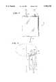
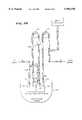
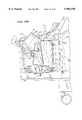
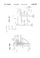
- FIG. 1is a diagrammatic view of an enhanced yield axial flow processing chamber that embodies the features of the invention
- FIG. 2is a diagrammatic view of the chamber shown in FIG. 1 operating in a centrifugation field;
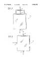
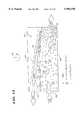
- FIG. 3is a diagrammatic view of the interior of the chamber shown in FIG. 1 when processing whole blood within the centrifugation field;
- FIG. 3Ais a graph showing the distribution of increasing regions of surface hematocrit along the interface formed in a blood separation chamber
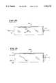
- FIGS. 4 and 5are diagrammatic views of prior art axial flow blood processing chambers
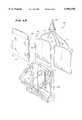
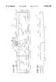
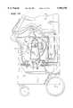
- FIGS. 6A and 6Bare a perspective views of a blood processing assembly that incorporates enhanced yield first and second stage axial flow processing chambers, each with an associated centrifuge holder shown in an opened position, with FIG. 6A showing the first stage holder and 6B showing the second stage holder;
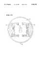
- FIG. 7Ais a top view of the blood processing assembly shown in FIG. 6 in position in a centrifuge;
- FIG. 7Bis a schematic view of the flow system associated with the blood processing assembly when being used to separate blood components
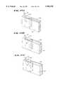
- FIG. 8is a perspective view of the first stage centrifuge holder associated with the assembly shown in FIG. 6A, when closed;
- FIG. 9Ais a plan view of the high-G surface of the first stage holder shown in FIG. 6A;
- FIG. 9Bis a plan view of the low-G surface of the first stage holder shown in FIG. 6A;
- FIG. 10Ais a perspective view of the high-G surface of the second stage holder shown in FIG. 6B;
- FIG. 10Bis a plan view of the contours of the second stage centrifugation chamber, when in its operative position in the centrifuge holder;
- FIG. 11is a diagrammatic view of an enhanced yield circumferential flow processing chamber that embodies the features of the invention.
- FIG. 12is a diagrammatic view of the chamber shown in FIG. 11 operating in a centrifugation field
- FIG. 13is a diagrammatic view of the interior of the chamber shown in FIG. 11 when processing whole blood within the centrifugation field;
- FIGS. 14 and 15are diagrammatic views of prior art circumferential flow blood processing chambers
- FIG. 16is a plan view of a blood processing assembly that incorporates an enhanced yield circumferential flow processing chamber that embodies the features of the invention
- FIG. 17is a view of the interior of the blood processing assembly shown in FIG. 16, taken between the low-G and high-G walls radially along the centrifugation field;
- FIG. 18is a plan view of an alternative blood processing assembly that incorporates an enhanced yield circumferential flow processing chamber that embodies the features of the invention.
- FIG. 19is a view of the interior of the blood processing assembly shown in FIG. 18, taken between the low-G and high-G walls radially along the centrifugation field;
- FIG. 20is a side view of a centrifuge that can be used in association with either one of the blood processing assemblies shown in FIGS. 16/17 or 18/19, showing the bowl and spool assemblies in their upraised and separated position;
- FIG. 21is a side view of the centrifuge shown in FIG. 20, showing the bowl and spool assemblies in their suspended and operating position;
- FIG. 22is an enlarged perspective view of one of the blood processing assemblies shown in FIGS. 16/17 or 18/19 being wrapped for use about the spool of the centrifuge shown in FIG. 20;
- FIG. 23is an enlarged perspective view, with portions broken away, of one of the blood processing assemblies shown in FIGS. 16/17 or 18/19 mounted for use on the bowl and spool assemblies of the centrifuge shown in FIG. 20;
- FIG. 24is a top interior section view, taken generally along line 24--24 in FIG. 23, of the processing chamber formed by the bowl and spool assemblies of the centrifuge shown in FIG. 20;
- FIGS. 25A/B/Care enlarged perspective views of an interior ramp used in association with either one of the blood processing assemblies shown in FIGS. 16/17 or 18/19 for controlling flow of PRP from the chosen assembly;
- FIG. 26is a view of the vortex conditions generated within the blood processing assembly shown in FIGS. 16/17 during use;
- FIG. 27is a single needle platelet collection system that can be used in association with either one of the blood processing assemblies shown in FIGS. 16/17 or 18/19;
- FIG. 28is a double needle platelet collection system that can be used in association with either one of the blood processing assemblies shown in FIGS. 16/17 or 18/19;
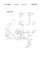
- FIG. 29is a plasma recirculation control system that can be used in association with either one of the blood processing systems shown in FIGS. 27 or 28;
- FIG. 30is a perspective view, with portions broken away and in section, of an interface control system mounted on the rotating (one omega) portion of the centrifuge shown in FIGS. 20 and 21 and used in association with the ramp shown in FIG. 25;
- FIG. 31Ais an enlarged perspective view of the rotating interface viewing head associated with the interface control system shown in FIG. 30;
- FIG. 31Bis a side section view showing the interior of rotating interface viewing head shown in FIG. 31A;
- FIG. 32is a schematic view of the light intensity control circuit associated with the interface control system shown in FIG. 30;
- FIGS. 33A/B/Care a series of diagrammatic views showing the operation of the interface control system shown in FIG. 30 during rotation of the centrifuge assembly;
- FIGS. 34A/Bare flow charts showing the operation of the interface control circuit associated with the interface control system shown in FIG. 30;
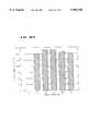
- FIGS. 35A/Bshow, respectively, the platelet counts and mean platelet volumes sampled during a 45 minute procedure using a separation chamber that embodies the features of the invention.
- FIGS. 36A/Bshow, respectively, the platelet counts and mean platelet volumes sampled during a 45 minute procedure using another separation chamber than embodies the features of the invention.
- FIGS. 1 to 3show, in diagrammatic fashion, a single stage axial flow centrifugal blood processing system.
- the systemincludes a chamber 10 that embodies the features of the invention.
- the systemseparates whole blood within the chamber 10 into red blood cells (RBC) and plasma rich in platelets (called platelet-rich plasma, or PRP).
- RBCred blood cells
- PRPplatelet-rich plasma
- WBwhole blood
- the systemincludes a holder 12 that rotates the chamber 10 about an axis 14 (see FIG. 2), to thereby create a centrifugal field within the chamber 10.
- the centrifugal fieldextends from the rotational axis 14 radially through the chamber 10.
- the chamber wall 16 closest to the rotational axis 14will be subject to a lower centrifugal force (or G-force) than the chamber wall 18 farthest away from the rotational axis 14. Consequently, the closer chamber wall 16 will be called the low-G wall, and the farthest chamber wall 18 will be called the high-G wall.
- the chamber 10While rotating, the chamber 10 receives WB through a first port 20.
- the WBfollows an axial flow path in the chamber 10. That is, it flows in a path that is generally parallel to the rotational axis 14 (as FIG. 2 best shows). Consequently, the chamber 10 will be called an axial flow blood processing chamber.
- the transverse top and bottom edges of the axial flow chamber 10are shorter than the longitudinal side edges (which lie along the axial flow path).
- the transverse top and bottom edgescan extend 360 degrees to form a bowl, the outer periphery of which constitutes an axial flow chamber.
- WBseparates within the chamber 10 under the influence of the centrifugal field into RBC and PRP.
- FIG. 3shows, the higher density RBC move toward the high-G wall 18, displacing the lighter density PRP toward the low-G wall 16.
- a second port 22draws the RBC from the chamber 10 for collection.
- a third port 24draws the PRP from the chamber 10 for collection.
- An intermediate layer called the interface 26forms between the RBC and PRP.
- the interface 26constitutes the transition between the formed cellular blood components and the liquid plasma component. Large amounts of white blood cells and lymphocytes populate the interface 26.
- Plateletstoo, can leave the PRP and settle on the interface 26. This settling action occurs when the radial velocity of the plasma near the interface 26 is not enough to keep the platelets suspended in the PRP. Lacking sufficient radial flow of plasma, the platelets fall back and settle on the interface 26.
- One aspect of the inventionestablishes flow conditions within the chamber 10 to "elute" platelets from the interface 26.
- the elutionlifts platelets from the interface 26 and into suspension in the PRP.
- the PRP collection port 24 and the WB inlet port 20are juxtaposed so that the PRP exits the chamber 10 in the same region where WB enters the chamber 10.
- the illustrated embodimentlocates the PRP collection port 24 on the same transverse edge of the chamber 10 as the WB inlet port 20. In FIGS. 1 to 3, this transverse edge is located physically at the top of the chamber 10.
- the inventionalso arranges the RBC collection port 22 and the PRP collection port 24 so that PRP exits the chamber 10 in a region opposite to the region where RBC exit the chamber 10, relative to the axial flow of WB in the chamber 10.
- the illustrated embodimentlocates the RBC collection port 22 on the transverse edge that is opposite to transverse edge where the WB inlet and PRP collection ports 20 and 24 are located.
- this transverse edgeis located physically at the bottom of the chamber 10.
- centrifugal fieldis not sensitive to "top” and "bottom” port placement.
- the particular "top edge” and “bottom edge” relationship of the ports 20; 22; and 24 shown in FIGS. 1 to 3could be reversed, placing the WB inlet and PRP collection ports 20 and 24 on the bottom edge and the RBC collection port 22 on the top edge.
- the chamber 10 shown in FIGS. 1 to 3differs significantly from prior axial flow blood separation chambers 10A and 10B, which FIGS. 4 and 5 show. As there shown, the prior chambers 10A and 10B do not place the PRP collection port 24 and the WB inlet port 20 on the same transverse edge of the chamber. Instead, the prior chambers 10A and 10B purposely separate these ports 20 and 24 on different edges of the chamber.
- the PRP collection port 24 and the WB inlet port 20occupy opposite transverse edges of the chamber.
- the PRP collection port 24occupies the top transverse edge
- the WB inlet port 20occupies the bottom transverse edge.
- the PRP collection port 24occupies a transverse (top) edge of the chamber, while the WB inlet port 20 occupies a longitudinal (side) edge.
- the RBC collection port 22occupies an opposite (bottom) transverse edge of the chamber. This arrangement locates the WB inlet port 20 between the PRP collection port 24 and the RBC collection port 22.
- the distance between the low-G wall 16 and the interface 26is preferably smaller in the region of the RBC collection port 22 than in the region of the PRP collection port 24.
- the illustrated embodimentachieves this result by uniformly tapering the low-G wall 16 toward the high-G wall 18 between the PRP collection port 24 and the RBC collection port 22.
- FIG. 3shows the tapering low-G wall 16 in phantom lines.
- the same resultcan be obtained without continuously or uniformly tapering the low-G wall 16 along the entire length of the axial flow path between the PRP collection port 24 and the RBC collection port 22.
- the low-G wall 16can begin its taper farther away from the PRP collection port 24 than FIG. 3 shows, closer to the region of the RBC collection port 22.
- the axial flow processing chamber 10configured according to this aspect of the invention serves to increase platelet yields due to the interplay of two principal dynamic flow conditions, one radial and the other axial in direction.
- the chamber 10produces a dynamic radial plasma flow condition near the PRP collection port 24.
- the radial flow conditionis generally aligned along the centrifugal force field.
- the radial plasma flow conditioncontinuously elutes platelets off the interface 26 into the PRP flow next to the PRP collection port 24.
- the chamber 10produces a dynamic axial plasma flow condition between the two ports 22 and 24.
- the axial flow conditionis generally transverse the centrifugal force field.
- the axial plasma flow conditioncontinuously drags the interface 26 back towards the PRP collection port 24, where the higher radial plasma flow conditions exist to sweep the platelets off the interface 26.
- FIG. 3diagrammatically shows the enhanced platelet separation effect due to these complementary radial and axial flow conditions.
- WBenters the chamber 10 at a given entry hematocrit, which indicates the volume of RBC per unit volume of WB.
- a typical healthy donorhas a predonation hematocrit of about 42.5%.
- the hematocrit of the blood lying on the boundary between the RBC and plasma along the interface 26(called the surface hematocrit) remains at or substantially the same as the entry hematocrit in the entry region R e of the chamber 10 near the WB inlet port 20.
- FIG. 3Ashows this entry region R e as lying to the left of the 0.40 surface hematocrit isoconcentration line (which is the same as the entry 40% hematocrit).
- the size of the entry region R evaries according to the hematocrit of the blood entering the chamber 10. For a given chamber configuration, the lower the entry hematocrit is, the smaller the entry region R e becomes.
- the size of the entry region R ealso depends upon the strength of the centrifugal field within the chamber and the surface area of the chamber.
- the surface hematocritsuccessively increases above its entry level outside the entry region R e along the length of the chamber 10 toward the terminal region R t , where separation is halted. This is because more red blood cells separate and collect toward the high-G wall 18 along the length of the chamber 10.
- FIG. 3Ashows the increasing surface hematocrit along the interface 26 as intersected by isoconcentration lines 0.6 (representing a 60% surface hematocrit) to 0.9 (representing a 90% surface hematocrit).
- the surface hematocritis least in the entry region R e of the chamber 10 near the WB inlet port 20.
- the velocity at which the RBC settle toward the high-G wall 18 in response to centrifugal forceis greatest in the entry region R e . Because the surface hematocrit is the least, there is more plasma volume to displace in the entry region R e .
- the purposeful arrangement of the ports 20; 22; and 24 in the separation chamber 10also contributes to further enhanced elution of platelets.
- the WB inlet port 20is diametrically spaced from the RBC collection port 22, but the WB inlet port 20 is alongside the PRP collection port 24. This isolation between the WB inlet port 20 and the RBC collection port 22 forces the RBC to traverse the entire axial length of the chamber 10 during processing. This maximizes its exposure to the centrifugal force field.
- the isolation between the RBC collection port 22 and the PRP collection port 24directs the RBC toward the RBC collection port 22. At the same time, it directs the PRP stream in the opposite direction toward the PRP collection port 24.
- the distance between the low-G wall 16 and the interface 26increases between the region of the RBC collection port 22 and the PRP collection port 24.
- the plasma layer along the interface 26increases in radial depth in the intended direction of PRP flow, i.e., away from the RBC collection port 22 and toward the axially spaced PRP collection port 24.
- the plasma near the RBC collection port 22is closer to the high-G centrifugation field than the plasma near the PRP collection port 24.
- This shift in the relative position of the plasma between the two ports 22 and 24causes the lighter plasma to move along the interface 26.
- the plasmamoves swiftly away from the relatively more confined region closer to the high-G field (i.e., next to the RBC collection port 22), toward the relatively more open region closer to the low-G field (i.e., next to the PRP collection port 24).
- the remaining minority of the platelet populationconstitutes platelets that are physically larger. These larger platelets typically occupy over 15 ⁇ 10 -15 liter per platelet (femtoliters, or cubic microns), and some are larger than 30 femtoliters. In comparison, most platelets average about 8 to 10 femtoliters (the smallest of red blood cells begin at about 30 femtoliters).
- the axial plasma flow conditions established along the interface 26 by the displaced low-G wall 16moves these larger, faster settling platelets with the interface 26.
- the axial plasma flowmoves the larger platelets toward the PRP collection port 24 into the region of high radial plasma flow.
- the high radial plasma flowlifts the larger platelets from the interface 26 for collection.
- the complementary flow conditionscontinuously lift platelets of all sizes from the interface 26 next to the PRP collection port 24. They work to free platelets of all sizes from the interface 26 and to keep the freed platelets in suspension within the PRP.
- the counterflow patternsserve to circulate the other heavier components of the interface 26 (the lymphocytes, monocytes, and granulocytes) back into the RBC mass, away from the PRP stream.
- the PRP exiting the PRP collection port 24carries a high concentration of platelets and is substantially free of the other blood components.
- FIGS. 6 to 10show the physical construction of a two stage axial flow system 27 that embodies the features and benefits already discussed, as well as additional features and benefits.
- the system 27includes an assembly 28 of two disposable separation and collection containers 31A and 31B linked by tubing to an umbilicus 29.
- the separation containers 31A/31B and associated tubingcan be made of low cost medical grade plastic materials, like plasticized PVC.
- the container 31Aconstitutes an axial flow chamber in which RBC and PRP are separated from whole blood in a first processing stage.
- the container 31Aembodies the features of the axial flow chamber 10, as previously described.
- the container 31Bconstitutes an axial flow chamber in which the PRP is further separated into platelet concentrate and platelet-depleted plasma (also called platelet-poor plasma) in a second processing stage.
- platelet concentratealso called platelet-poor plasma
- PPPplatelet-poor plasma
- the specification and drawingswill refer to platelet concentrate as PC and platelet-poor plasma as PPP.
- the container 31Bembodies other aspects of the invention, which will be described in greater detail later.
- the assembly 28can be used in association with a commercially available blood processing centrifuge, like the CS-3000® Blood Separation Centrifuge made and sold by the Fenwal Division of Baxter Healthcare Corporation (a wholly owned subsidiary of the assignee of the present invention).
- a commercially available blood processing centrifugelike the CS-3000® Blood Separation Centrifuge made and sold by the Fenwal Division of Baxter Healthcare Corporation (a wholly owned subsidiary of the assignee of the present invention).
- the commercially available centrifugeincludes a rotor 30 that carries two holders 32A and 32B, one for each container 31A and 31B.
- FIG. 6Ashows the holder 32A for the first container 31A.
- FIG. 6Bshows the holder 32B for the second container 31B.
- each holder 32A/32Bcan be pivoted opened to receive its separation container 31A/31B.
- Each holder 32A/32Bcan then be pivoted closed (as FIG. 8 shows) to capture and enclose the associated separation container 31A/31B during processing.
- the rotor 30rotates (typically at about 1600 RPM), subjecting the holders 32A/32B and their entrapped separation containers 31A/31B to a centrifugal force field.
- the centrifugal forceis field is about 375 G's along the high-g wall of the assembly 28.
- the first stage container 31Aincludes a series of ports through which the tubing umbilicus 29 conveys fluid.
- the container 31Areceives WB through the port 34 for centrifugal separation into RBC and PRP.
- the ports 36 and 38convey separated RBC and PRP, respectively, from the first container 31A.
- PRPis conveyed from the first container 31A into the second stage container 31B.
- the second container 31Breceives PRP through the port 35 for centrifugal separation into PC and PPP.
- the port 37conveys PPP from the container 31B, leaving the PC behind within the container 31B for collection.
- a normally closed outlet port 39is provided to later convey the PC from the container 31B.
- the umbilicus 29connects the rotating separation containers 31A/31B with pumps and other stationary components located outside the rotor 30.
- the stationary componentsinclude a pump P1 for conveying WB into the first container 31A.
- a pump P2conveys PRP from the first container 31A to the second container 31B.
- An interface detector 33senses the boundary between the RBC and plasma to control the operation of the pump P2.
- the pump P2pulls PRP away from the container 31A, until the detector 33 senses the presence of RBC. This indicates that the boundary between the RBC and the plasma has "spilled” past the detector 33.
- the pump P2then pumps back toward the first container 31A until the sensed "spill-over” clears the interface detector 33.
- the pump P2then reverses again to pull PRP away from the container 31A until the detector 33 senses another "spill-over.” This process repeats itself.
- a non-rotating (zero omega) holder(not shown) holds the upper portion of the umbilicus 29 in a non-rotating position above the rotor.
- the holder 40(see FIG. 7A) rotates the mid-portion of the umbilicus 29 at a first (one omega) speed about the rotor 30.
- the holder 42(also see FIG. 7A) rotates the lower end of the umbilicus 29 at a second speed twice the one omega speed (the two omega speed).
- the rotor 30also rotates at the two omega speed.
- Each separation container 31A and 31Bconforms to the interior configuration defined by its respective holder 32A and 32B, when closed.
- the holder 32A for the first stage container 31Aincludes a preformed high-G surface 44, also shown in FIG. 9A.
- the holder 32Aalso includes a facing preformed low-G surface 46, also shown in FIG. 9B.
- the surface 46is formed on a pressure plate 47 that is inserted into the holder 32A.
- the holder 32AWhen closed, the holder 32A sandwiches the flexible separation container 31A between the high-G surface 44 and the surface of the low-G surface 46 (as FIG. 8 shows).
- the high-G surface 44includes a prescribed recessed region 48 from which a pattern of raised sealing surfaces 50 project.
- the pressure plate 47presses the low-G surface 46 against the sealing surfaces 50.
- the pressure plate surface 46crimps the walls of the separation container 31A closed along these sealing surfaces 50. This forms a prescribed peripherally sealed region within the container 31A occupying the recessed region 48.
- the peripherally sealed region of the container 31Aexpands against the high-g surface 44 and the facing low-g surface of the pressure plate 46, assuming their prescribed contours.
- the pattern of the raised sealing surfaces 50establishes first, second, and third port regions 52; 54; and 56 extending into the recessed region 48.
- the first port region 52receives the WB inlet port 34 of the container 31A.
- the second port region 54receives the RBC collection port 36 of the container 31A.
- the third port region 56receives the PRP collection port 38 of the container 31A.
- the first port region 34(receiving WB inlet port 34) and the third port region 56 (receiving the PRP collection port 38) enter the recessed region 48 on the same transverse edge of the high-G surface 44 (which is shown as the top edge in the drawings).
- the second port region 54(receiving the RBC collection port 36) enters the recessed region 48 through a passage 49 that opens on the opposite transverse edge of the high-G surface 44 (which is shown as the bottom edge in the drawings).
- the relative orientation of the transverse top and bottom edgescould be reversed.
- mating regions 52A; 54A; and 56A on the low-G pressure plate 46register with the first, second, and third port regions 52; 54; and 56 on the high-G surface 44 to receive the WB, RBC and PRP ports 34; 36; and 38 (see FIG. 8 also).
- the low-G pressure plate surface 46preferably tapers outward toward the high-G surface at a slope of about 0.25 degree.
- the holder 32AWhen closed, the holder 32A thereby shapes the peripherally sealed region of the container 31A to establish an axial flow processing chamber 10 like that shown in FIGS. 1 to 3.
- the first stage separation chamber 32Bpreferably presents an effective collection area of between about 70 to about 120 cm 2 , with an associated processing volume of between about 45 ml to about 100 ml.
- the holder 32B for the second stage container 31Blike the other holder 32A, includes a preformed high-G surface 51, which FIG. 10A also shows.
- the holder 32Balso includes a facing preformed low-G pressure surface 53 formed on an insertable pressure plate 55.
- the high-G surface 51 of the holder 32Bincludes a recessed region 57 from which a pattern of raised sealing surfaces 59 project (see FIGS. 6B and 10A).
- the pattern of the raised sealing surfaces 59establishes first and second regions R1 and R2 within the chamber 61.
- the first region R1communicates with the PRP inlet port 35 of the container 31B.
- the second port region R2communicates with the PPP collection port 37 of the container 31B.
- the raised sealing surfaces 59also establish an interior wall 63 that separates the first and second regions R1 and R2.
- the wall 63stretches into the chamber 61, extending in the same direction as the axial flow path.
- the wall 63terminates within the chamber 61 to form a passage 65 linking the two regions R1 and R2. It should be appreciated that position of the wall 63 within the chamber 61 can vary. It can be closer to the PRP inlet port 35 than shown in FIG. 10B, thereby decreasing the size of the first region R1, and vice versa.
- the configuration of the second stage chamber 61is like that shown in FIGS. 11 to 13 in Cullis et al. U.S Pat. No. 4,146,172.
- the Cullis et al. '172 Patentis incorporated into this Specification by reference.
- a chamber like that shown in FIGS. 11 to 13 of the Cullis et al. '172 Patenthas been in widespread commercial use in association with the CS-3000® Blood Separation Centrifuge for use in separating PC and PPP from PRP.
- the commercial chamberbears the trade designation "A-35 Chamber.”
- the prior A-35 Chambertypically has a collection area of about 160 cm 2 for separating PRP into PC and PPP. When used for this purpose, this chamber typically presents a radial thickness (or depth) on the order of about 1.4 cm. The chamber thereby has a processing volume of about 200 mL.
- the larger processing volumewas believed to be beneficial, because it gave the platelets more time to separate (or “sediment") from the PRP within the chamber.
- Conventional wisdomalso believed that the larger desired processing volume in the second stage chamber would subject the platelets to less damage or activation due to shear stress during processing (see, e.g., column 10, lines 26 to 39 of the Cullis et al. '172 Patent).
- the axial flow processing chamber 61 shown in FIG. 10Bhas a significantly smaller processing volume, compared to the prior A-35 Chamber.
- the chamber 61 configured according to the inventionpresents the same collection area as the prior A-35 Chamber (i.e., about 160 cm 2 ), but has a maximum radial (or channel) depth of only 2 mm.
- the chamber 61presents a processing volume of just 30 mL, compared to the 200 mL processing volume typical for the prior A-35 Chamber.
- the chamber 61provides a significant increase in platelet collection efficiencies, compared to the prior A-35 Chamber.
- the 30 ml ChamberCompared to the A-35 Chamber, the 30 ml Chamber provided increased platelet yields without damage or activation of the platelets.
- the platelet concentrate collected using the 30 ml Chambercould be filtered immediately after resuspension, without platelet loss.
- platelet concentrate collected using the A-35 Chamberrequired a rest period of at least 2 hours before it could be filtered without incurring a significant loss in platelet count.
- One aspect of the inventionprovides a new dimensionless parameter ( ⁇ ) that more accurately characterizes the combined attributes of angular velocity, channel thickness, kinematic viscosity, and axial height of the platelet separation chamber 61.
- the new parameter ( ⁇ )is expressed as follows:
- ⁇is the angular velocity (in rad/sec);
- his the radial depth (or thickness) of the chamber (in cm);
- ⁇is the kinematic viscosity of the fluid being separated (in cm 2 /sec).
- Zis the axial height of the chamber (in cm).
- the parameter ( ⁇ ) valueclearly characterizes and differentiates the unique nature and domain of the flow regime established within the chamber 61 (referred to as the "New" chamber), compared to the conventional A-35 chamber.
- the parameter ( ⁇ ) value for the prior A-35 Chamberis 5109.
- the parameter ( ⁇ ) value for the chamber that embodies the features of the inventionis only 14, less than 1% of the prior chamber.
- a parameter ( ⁇ ) value for a chamberthat is less than about 700 will produce significantly greater platelet yields.
- the parameter ( ⁇ ) value of a given chamberincreasingly exceeds about 700, the chamber produces flow conditions that lead to greater overall shear stress during processing (leading to platelet activation) and to greater Coriolis-effect swirling (which limits the effective surface area available for platelet perfusion).
- the new parameter ( ⁇ ) valueexpresses for a given rotating frame of reference what the magnitude of Coriolis-effect swirling and shear stress will be.
- the parameter ( ⁇ ) valuehas the same meaning whether the flow within the chamber is axial (i.e., along the axis of rotation) or circumferential (i.e., about the axis of rotation). Regardless of the direction of flow with respect to the rotational axis, the lower the absolute parameter ( ⁇ ) value is for a given system, the lower will be the expected magnitude of Coriolis-effect swirling in the system.
- the chamber 61has a parameter ( ⁇ ) value that is less than about 700, it is better perfused during processing and subjects the platelets to less shear stress, even at dramatically reduced chamber depths (i.e. radial thickness).
- FIGS. 11 to 13show, in diagrammatic fashion, a circumferential flow centrifugal blood processing chamber 58 that embodies the features of the invention.
- the chamber 58rotates on a rotor 60 about an axis 62 (see FIG. 12), to thereby create a centrifugal field within the chamber 58.
- the centrifugal fieldextends radially from the axis through the chamber 58.
- the chamber wall 64 closest to the axisconstitutes the low-G wall
- the chamber wall 66 farthest from the axisconstitutes the high-G wall.
- the chamber 58While rotating, the chamber 58 receives WB through a first port 68.
- the WBfollows a circumferential flow path in the chamber 58; that is, it flows in a circumferential path about the rotational axis 62 (as FIG. 12 best shows). For this reason, the chamber 58 is called a circumferential flow blood processing chamber.
- the transverse top and bottom edges of the chamber 58(which lie along the circumferential flow path) are usually longer than the longitudinal side edges (which lie across the circumferential flow path).
- the circumferential flow chamber 58usually forms the shape of a tube that is elongated in the direction of rotation. Still, other configurations defining a circumferential flow path can be used.
- WBseparates within the tubular chamber 58 under the influence of the centrifugal field into RBC and PRP.
- FIG. 13shows, the higher density RBC move toward the high-G wall 66, displacing the lighter density PRP toward the low-G wall 64.
- the interface 26(previously described) forms between them.
- a second port 70draws the RBC from the chamber 58 for collection.
- a third port 72draws the PRP from the chamber 58 for collection.
- the PRP collection port 72 and the WB inlet port 68are juxtaposed so that the PRP exits the circumferential flow chamber 58 in the same region where WB enters the chamber 58.
- the PRP collection port 72is located along the same longitudinal side edge of the circumferential flow chamber 58 as the WB inlet port 68.
- the RBC collection port 70 and the PRP collection port 72are arranged so that PRP exits the chamber 58 in a region opposite to the region where RBC exit the chamber 58, relative to the circumferential flow of WB in the chamber 58.
- the RBC collection port 70is located on the longitudinal side edge that is opposite to longitudinal side edge where the WB inlet and PRP collection ports are located.
- the chamber 58 shown in FIGS. 11 to 13differs significantly from prior circumferential flow blood separation chambers 58A and 58B, which are shown in FIGS. 14 and 15.
- the prior circumferential flow chambers 58A/Bpurposely located the PRP collection port 72 away from the WB inlet port 68.
- the PRP collection port 72occupies one side edge, diametrically opposite to the RBC collection port 70, which occupies the other side edge.
- the WB inlet port 68is located in a side wall of the chamber 58A between the two side edges.
- the PRP collection port 72occupies one side edge, while the WB inlet port 68 and the RBC outlet port occupies the opposite side edge, oppositely spaced away from the PRP collection port 72 relative to the circumferential flow of WB in the chamber 58B.
- no portsare located on the top and bottom transverse edges of the chamber 58B.
- Neither chamber 58A and 58Bhas a port with an axis that extends parallel to the axis of rotation.
- FIG. 13diagrammatically shows the enhanced platelet separation effect due to the adjacent positions of the WB inlet port 68 and the PRP collection port 72 in the circumferential flow chamber 58 that embodies the invention.
- the effectis generally the same as that shown in FIG. 3, except the chamber 58 is oriented differently to establish the circumferential flow pattern.
- the PRP collection port 72draws PRP from the chamber 58 where velocity at which the RBC settle toward the high-G wall 66 in response to centrifugal force is the greatest, i.e., next to the WB inlet port 68.
- the radial plasma velocityis the greatest to lift platelets from the interface 26, and to keep them in suspension within the plasma for transport out the PRP collection port 72.
- the WB inlet port 68is oppositely spaced from the RBC collection port 70 (in the circumferential flow direction), forcing the RBC to traverse the entire axial length of the chamber 58, thereby maximizing their exposure to the centrifugal separation forces.
- the isolation between the RBC collection port 70 and the PRP collection port 72also directs the RBC toward the RBC collection port 70, while directing the PRP stream in the opposite direction toward the PRP collection port 72.
- the low-G wall 64is preferably displaced inward toward the interface 26 near the RBC collection port 70.
- the radial distance between the low-G wall 64 and interface 26is greater near the PRP collection port 72 than near the RBC collection port 70.
- the displaced low-G wall 64causes the lighter plasma to move along the interface 26 swiftly away from the relatively more confined region next to the RBC collection port 70, toward the relatively more open region next to the PRP collection port 72.
- the circumferential plasma flowdrags the interface 26--and larger, faster settling platelets entrapped within in--continuously toward the PRP collection port 72, where the radial plasma velocities are the greatest to supply the greatest elution effect.
- the counterflow patternsalso serve to circulate the other heavier components of the interface (lymphocytes, monocytes, and granulocytes) back into the RBC mass, away from the PRP stream.
- the low-G wall 64continuously tapers in the direction of the circumferential flow path, e.g., away from the PRP collection port 72 and in the direction of axial flow path of the WB.
- the same resultcan be obtained without continuously or uniformly tapering the low-G wall 16 along the entire length of the axial flow path between the PRP collection port 72 and the RBC collection port 70.
- the low-G wall 16can begin its taper farther away from the PRP collection port 24 than FIG. 13 shows, closer to the region of the RBC collection port 70.
- FIGS. 16 and 17show the physical construction of one preferred circumferential flow chamber assembly 74 that embodies the features of the invention.
- FIGS. 25 and 26show the physical construction of an alternative circumferential flow assembly 76.
- Either assembly 74 or 76can be used in association with a blood processing centrifuge 78, like that shown in FIGS. 18 and 19. Further details of this centrifuge construction are set forth in copending U.S. patent application Ser. No. 07/814,403, filed Dec. 23, 1991 and entitled "Centrifuge with Separable Bowl and Spool Elements Providing Access to the Separation Chamber".
- the centrifuge 78includes a bowl element 80 and a spool element 82.
- the bowl and spool elements 80 and 82can be pivoted on a yoke 85 between an upright position, as FIG. 20 shows, and a suspended position, as FIG. 21 shows.
- the bowl and spool elements 80 and 82When upright, the bowl and spool elements 80 and 82 are presented for access by the user.
- a mechanismpermits the spool and bowl elements 80 and 82 to assume a mutually separated position, as FIG. 20 shows. In this position, the spool element 80 is at least partially out of the interior area of the bowl element 82 to expose the exterior spool surface for access.
- FIG. 22when exposed, the user can wrap either circumferential flow chamber assembly 74 or 76 about the spool element 82.
- the mechanismalso permits the spool and bowl elements 80 and 82 to assume a mutually cooperating position, as FIG. 23 shows. In this position, the spool element 82 and the chosen circumferential flow chamber assembly 74 or 76 are enclosed within the interior area of the bowl element 80, as FIG. 23 shows.
- a processing chamber 83is formed between the interior of the bowl element 80 and the exterior of the spool element 82.
- the chosen circumferential flow chamber assembly 74 or 76is carried with and assumes the contours of the processing chamber 83.
- the spool and bowl elements 80 and 82When closed, the spool and bowl elements 80 and 82 can be pivoted as an assembly into a suspended position, as FIG. 21 shows. When suspended, the bowl and spool elements 80 and 82 are in position for operation. In operation, the centrifuge 78 rotates the suspended bowl and spool elements 80 and 82 about an axis.
- each circumferential flow chamber assembly 74 and 76provides multi-stage processing.
- a first stageseparates RBC and PRP from WB.
- a second stageseparates PC and PPP from the PRP.
- FIGS. 16/17 and 18/19show the interior of the alternative circumferential flow chambers divided into two side-by-side processing compartments 84 and 86.
- centrifugal forces in the first compartment 84separate whole blood into RBC and PRP.
- Centrifugal forces in the second processing compartment 86separate the PRP from the first stage into PC and PPP.
- a first peripheral seal 88forms the outer edge of the circumferential flow chamber assembly 74 or 76.
- a second interior seal 90divides the circumferential flow chamber assembly 74 or 76 into the first processing compartment 84 and the second processing compartment 86.
- the second seal 90extends generally parallel to the rotational axis of the chamber assembly 74 or 76; that is, it extends across the circumferential flow of the chamber assembly 74 or 76.
- the second seal 90constitutes a longitudinal edge common to both first and second processing compartments 84 and 86.
- Each processing compartment 84 and 86serves as a separate and distinct separation chamber and will therefore be referred to as such.
- each alternative circumferential flow chamberfive ports 92/94/96/98/100 open into the compartmentalized areas formed in the processing chamber assembly 74 or 76.
- the ports 92/94/96/98/100are arranged side-by-side along the top transverse edge of the respective chamber 84 and 86.
- the ports 92/94/96/98/100are all axially oriented; that is, their axes are aligned with the axis of rotation, transverse the circumferential fluid flow path within the chamber assembly 74 or 76 itself.
- Three ports 92/94/96serve the first chamber 84.
- Two ports 98/100serve the second chamber 86.
- an umbilicus 102(see FIG. 24) attached to the ports 92/94/96/98/100 interconnects the first and second chambers 84 and 86 with each other and with pumps and other stationary components located outside the rotating components of the centrifuge 78.
- a non-rotating (zero omega) holder 104holds the upper portion of the umbilicus 102 in a non-rotating position above the suspended spool and bowl elements 80 and 82.
- a holder 106 on the yoke 85rotates the mid-portion of the umbilicus 102 at a first (one omega) speed about the suspended spool and bowl elements 80 and 82.
- Another holder 108rotates the lower end of the umbilicus 102 at a second speed twice the one omega speed (the two omega speed), at which the suspended spool and bowl elements 80 and 82 also rotate.
- this known relative rotation of the umbilicuskeeps it untwisted, in this way avoiding the need for rotating seals.
- the two omega speed at which the suspended spool and bowl elements 80 and 82 rotateis about 3400 RPM.
- 3400 RPMwill develop a centrifugal force field of about 900 G's along the high-C wall 66 of the chambers 84 and 86.
- the first port 92comprises the previously described PRP collection port (identified by reference numeral 72, as in FIGS. 11 to 13).
- the second port 94comprises the previously described WB inlet port (identified by reference numeral 68, as in FIGS. 11 to 13).
- the third port 96comprises the previously described RBC collection port (identified by reference numeral 70, as in FIGS. 11 to 13).
- a third interior seal 110is located between the PRP collection port 72 and the WB inlet port 68.
- the third seal 110includes a first region 112 that is generally parallel to the second interior seal 90, thereby extending across the circumferential WB flow path.
- the third interior seal 110then bends in a dog-leg portion 114 away from the WB inlet port 68 in the direction of circumferential WB flow.
- the dog-leg portion 114terminates beneath the inlet of the PRP collection port 72.
- a fourth interior seal 116is located between the WB inlet port 68 and the RBC collection port 70.
- the fourth seal 116includes a first region 118 tat is generally parallel to the second and third interior seals 90 and 110, thereby extending across the circumferential WB flow path.
- the fourth interior seal 116then bends in a dog-leg portion 120 away from the RBC collection port 70 in the direction of circumferential WB flow.
- the dog-leg portion 120extends beneath and beyond the dog-leg portion 114 of the third seal 110. It terminates near the longitudinal side edge of the first chamber 84 that is opposite to the longitudinal side edge formed by the second interior seal 90.
- the third and fourth interior seals 110/116form a WB inlet passage 122 that first extends along the axis of rotation (i.e., between the first regions 112/118 of the two seals 110/116).
- the WB inlet passage 122then bends to open in the direction of intended circumferential flow within the first chamber 84 (i.e., between the dog-leg portions 114/120 of the two seals 110/116).
- the WB inlet passage 122first channels WB away from the WB inlet port 68 in an axial flow path. It then channels WB circumferentially, directly into the circumferential flow path, where separation into RBC and PRP begins.
- the third interior seal 110also forms a PRP collection region 124 within the first chamber 84 (i.e., between the third seal 110 and the adjacent upper portion of the first peripheral seal 88).
- the fourth interior seal 116, the second interior seal 90, and the lower regions of the first peripheral seal 88form a RBC collection passage 126 that extends first along the axis of rotation (i.e., between the second interior seal 90 and the fourth interior seal 116).
- the RBC collection passage 126then bends in a circumferential path to open near the end of the intended WB circumferential flow path (i.e., between the dog-leg portion 120 of the fourth seal 116 and the lower region of the peripheral seal 88).
- the first port 92comprises the RBC collection port (identified by reference numeral 70, as in FIGS. 11 to 13).
- the second port 94comprises the PRP collection port (identified by reference numeral 72, as in FIGS. 11 to 13).
- the third port 96comprises the WB inlet port (identified by reference numeral 68, as in FIGS. 11 to 13).
- a third interior seal 110is located between the PRP collection port 72 and the WB inlet port 68.
- the seal 110includes a first region 112 that is generally parallel to the second interior seal 90. It then bends in a dog-leg portion 114 away from the WB inlet port 68 in the direction of circumferential WB flow. The dog-leg portion 114 terminates beneath the inlet of the PRP collection port 72.
- the second and third interior seals 90 and 110form a WB inlet passage 122, like the WB inlet passage 122 associated with the chamber 84 shown in FIG. 16, except in a different location within the chamber.
- a fourth interior seal 116is located between the PRP collection port 72 and the RBC collection port 70.
- the fourth seal 116includes a first region 118 that is generally parallel to the second and third interior seals 90 and 110, thereby extending across the circumferential flow path.
- the fourth interior seal 116then bends in a dog-leg portion 120 away from the PRP collection port 72 in the direction of circumferential WB flow. It terminates near the longitudinal side edge of the first chamber 84 that is opposite to the longitudinal side edge formed by the second interior seal 90.
- the fourth interior seal 116 and the upper regions of the first peripheral seal 88form a RBC collection passage 126, like the RBC collection passage 126 shown in FIG. 16, except that it is located at the top of the chamber 84, instead of at the bottom.
- the third and fourth interior seals 110 and 116 togetheralso form a PRP collection region 124 within the first chamber, like the PRP collection region 124 shown in FIG. 16.
- each alternative circumferential flow chamber assembly 74 or 76The dynamic flow conditions within each alternative circumferential flow chamber assembly 74 or 76 are the same. These conditions direct PRP toward the PRP collection region 124 for collection through the inlet of the PRP collection port 72.
- the WB inlet passage 122channels WB directly into the circumferential flow path immediately next to the PRP collection region 124.
- the radial flow rates of plasmaare greatest to lift platelets free of the interface and into the PRP collection region 124.
- the RBC collection passage 126receives RBC at its open end and from there channels the RBC to the RBC collection port 70.
- the WB inlet passage 122channels WB directly into the flow path at one end of the first chamber 84, and the RBC collection passage 126 channels RBC out at the opposite end of the flow path.
- each alternative circumferential flow chamber assembly 74 and 76(as FIGS. 17 and 19 respectively show), the low-G wall 64 of the first chamber 84 is offset toward the high-G wall 66 near the RBC collection region.
- the low-G wall 64tapers into the chamber 84 in the direction of circumferential WB flow.
- the taperproceeds from the second interior seal 90 toward the opposite longitudinal end of the chamber.
- FIG. 13shows the tapering low-G wall 64 from another perspective.
- the tapering low-G wall 64includes a stepped-up barrier 128 or dam in the region where the RBC collection passage 126 opens. As FIGS. 16 and 18 show for their respective chamber assembly, the stepped-up barrier 128 extends from the low-G wall 64 across the entire chamber 84.
- the stepped-up barrier 128extends into the RBC mass and creates a restricted passage 129 between it and the facing high-G wall 66.
- the restricted passage 129allows RBC present along the high-G wall 66 to move beyond the barrier 128 for collection by the RBC collection passage 126.
- the stepped-up barrier 128blocks the passage of the PRP beyond it, keeping the PRP within the dynamic flow conditions leading to the PRP collection region 124.
- the low-G wall 64tapers about 2 mm into the chamber 74 where it joins the barrier 128.
- the barrier 128extends from there at about a 45 degree angle toward the high-G wall 66, forming a raised planar surface.
- the passage 129 formed between the planar surface and the high-G wall 66is about 1 mm to 2 mm in radial depth and about 1 mm to 2 mm in circumferential length.
- the configuration of the low-G wall 64creates a swift counterflow of plasma from the RBC collection region toward the PRP collection region 124.
- the desired contours for the low-G wall 64 of the alternative chamber assemblies 74 and 76can be preformed on the exterior surface of the spool element 82.
- the interior surface of the bowl element 82is isoradial with respect to the rotational axis.
- the dog leg portion 120 of the RBC collection passage 126is tapered. Due to the taper, the passage 126 presents a greater cross section where it opens into the chamber 84 than it does where it joins the axial first region 118 of the RBC collection passage 126. FIG. 13 shows this taper from another perspective. In the illustrated and preferred embodiment, the dog leg portion 120 tapers from a width of about 1/4 inch to 1/8 inch.
- the taper of the dog leg portion 120is preferably gauged relative to the taper of the low-G wall 64 to keep the cross sectional area of the RBC collection passage 126 substantially constant. This keeps fluid resistance within the passage 126 relatively constant, while maximizing the available separation and collection areas outside the passage 126.
- the taper of the dog leg portion 120also facilitates the removal of air from the passage 126 during priming.
- a ramp 130extends from the high-G wall 66 across the PRP collection region 124 in each alternative chamber assembly 74 and 76.
- the ramp 130forms a tapered wedge that restricts the flow of fluid toward the PRP collection port 72.
- the ramp 130forms a constricted passage 131 along the low-G wall 64, along which the PRP layer extends.
- a hinged flap 132extends from and overhangs a portion of the spool element 82.
- the flap 132is preformed to present the desired contour of the ramp 130.
- the flap 132When flipped down (as FIG. 22 shows in solid lines), the flap 132 is sandwiched between the chosen chamber assembly 74/76 and the surrounding bowl element 80. The flap 132 presses against the adjacent flexible wall of the chamber assembly 74/76, which conforms to its contour to form the ramp 130 within the chamber 84.
- the ramp 130diverts the fluid flow along the high-G wall 66. This flow diversion changes the orientation of the interface 26 between the RBC (shown shaded in FIGS. 25A/B/C) and the PRP (shown clear in FIGS. 25A/B/C) within the PRP collection region 124.
- the ramp 130displays the interface 26 for viewing through a side wall of the chamber assembly 74/76 by an associated interface controller 234 (that FIGS. 30 and 31 show).
- the interface controller 234Monitors the location of the interface 26 on the ramp 130. As FIGS. 25A/B/C show, the position of the interface 26 upon the ramp 130 can be altered by controlling the relative flow rates of WB, the RBC, and the PRP through their respective ports 68/70/72.
- the controller 234caries the rate at which PRP is drawn from the chamber 84 to keep the interface 26 at a prescribed location on the ramp 26 (which FIG. 25B shows), away from the constricted passage 131 that leads to the PRP collection port 72.
- the ramp 130 and associated interface controller 134keep RBC, white blood cells, and lymphocytes present in the interface 26 from entering the PRP collection port 72.
- the collected PRPis thereby essentially free of the other cellular components present in the interface 26.
- the fourth port 98constitutes a PPP collection port 136
- the fifth port 100constitutes a PRP inlet port 138.
- the fourth port 98constitutes the PPP inlet port 138
- the fifth port 100constitutes the PPP collection port 136.
- the umbilicus 102connects the PRP collection port 72 of the first chamber 84 with the PRP inlet port 138 of the associated second chamber 86.
- the second chamber 86thereby receives PRP from the first chamber 84 for further separation into PPP and PC.
- the umbilicus 102conveys separated PPP from the second chamber 86 through the associated PPP collection port 136.
- the PCremains behind in the second chamber 86 for later resuspension and collection.
- a fifth interior seal 140extends between the PRP inlet port 138 and the PPP collection port 136.
- the fifth seal 140includes a first region 142 that is generally parallel to the second seal 90, thereby extending across the circumferential flow path.
- the fifth interior seal 140then bends in a dog-leg portion 144 away from the PRP inlet port 138 in the direction of circumferential PRP flow within the second chamber 86.
- the dog-leg portion 144terminates near the longitudinal side edge of the second chamber 86 that is opposite to the longitudinal side edge formed by the second interior seal 90.
- the fifth interior seal 140, the second interior seal 90, and the lower regions of the first peripheral seal 88together form a PPP collection passage 146 that extends first along the axis of rotation (i.e., between the second interior seal 90 and the fifth interior seal 140) and then bends in a circumferential path to open near the end of the intended PRP circumferential flow path (i.e., between the dog-leg portion 144 of the fifth seal 140 and the lower region of the peripheral seal 88).
- the PPP collection passage 146receives PPP at its open end and from there channels the PPP to the PPP collection port 136.
- a similar PPP collection passage 146is formed between the fifth interior seal 140 and the upper region of the peripheral seal 88.
- the centrifugal forces generated during rotation of the chamberseparate the PRP into PC and PPP.
- the more dense PCseparate out into a layer that extends along the high-G wall 66.
- the less dense PPPis displaced toward the low-G wall 64 for collection through the PPP collection passage 146.
- the inventorhas discovered that the introduction of PRP along an axial flow path parallel to the axis of rotation into a circumferential flow path about the axis of rotation creates a non-turbulent vortex region 148, called a Taylor column, at the outlet of the PRP inlet port 138, as FIG. 26 shows.
- the vortex region 148circulates about an axis that is aligned with the axis of the PRP inlet port 138.
- the vortex region 148stretches from the outlet of the port 138 longitudinally across the circumferential flow path of the chamber 86. As FIG. 26 shows, the vortex region 148 circulates the PRP about its axis and directs it into the desired circumferential flow path within the chamber 86.
- axial flow velocitydecreases in a generally linear fashion across the circumferential flow path of the chamber 86. This occurs as the axial flow of fluid entering the chamber 86 perfuses uniformly into a circumferential flow entering the separation zone.
- a similar vortex region 148forms at the opposite longitudinal end of the second chamber 86 at the entrance to the PPP collection passage 146, as FIG. 26 also shows.
- the vortex region 148 created at the outlet of the PRP inlet port 138uniformly disperses PRP in the desired circumferential flow path into the centrifugal field. This maximizes the exposure of the entering PRP to the effects of the centrifugal field across the effective surface area of- the second chamber 86. Maximum possible separation of PC from the entering PRP results.
- vortex region 148 flow conditionsare formed in the first chamber 84 as well, where fluid either enters or leaves the established circumferential flow path through an axial flow path. As FIG. 26 shows, a vortex region 148 condition thereby forms at the entrance of the WB inlet passage 122. Another vortex region 148 condition forms at the opposite longitudinal end at the entrance of the RBC collection passage 126.
- the low-G wall 64preferably tapers into the second chamber 86 in the direction of circumferential PRP flow. The taper proceeds from the second interior seal 90 toward the opposite longitudinal end of the second chamber 86.
- the circumferential leg of the associated PPP collection passage 146is tapered. Due to the taper, the leg presents a greater cross section where it opens into the second chamber than it does where it joins the axial portion of the PPP collection passage 146. In the illustrated and preferred embodiment, the leg tapers from a width of about 1/4 inch to 1/8 inch.
- the taper of the circumferential leg of the PPP collection passage 146is preferably gauged relative to the taper of the low-G wall 64 to keep the cross sectional area of the PPP collection passage 146 substantially constant. This keeps fluid resistance within the passage 146 relatively constant.
- the taper of the circumferential leg of PPP collection passage 146also facilitates the removal of air from the passage 146 during priming.
- Table 2shows the various dimensions of a representative embodiment of a processing chamber of the type shown in FIGS. 16/17 or 18/19. Dimensions A through F referenced in Table 2 are identified for their respective chamber assemblies in FIGS. 16 and 18.
- the two stage circumferential flow chambers shown in either FIGS. 16/17 or FIGS. 18/19can be used to do continuous platelet collection.
- the chamberscan be used in associated either with a system 150 that employs one phlebotomy needle (as FIG. 27 shows) or with a system 152 that employs two phlebotomy needles (as FIG. 28 shows).
- an associated processing controller 154automates the collection procedure to the fullest extent possible.
- the platelet collection system 150 shown in FIG. 27employs one, single lumen phlebotomy needle 156.
- FIG. 21generally depicts this single needle system 150 when mounted for use on the centrifuge 78.
- the processing controller 154operates the single needle system 150 in a draw cycle and a return cycle.
- the controller 154supplies the donor's WB through the needle 156 to a chosen one of the processing chamber assemblies 74/76. There, the WB is centrifugally separated into RBC, PC, and PPP.
- the controller 154returns RBC and PPP to the donor through the needle 156, while separation within the chosen processing chamber assembly 74/76 continues without interruption.
- the harvested PCis retained for long term storage. If desired, all or some PPP can be retained for storage, too.
- the system 150includes a draw reservoir 158, which pools a quantity of the donor's WB during the draw cycle.
- the system 150also includes a return reservoir 160, where a quantity of RBC collect for periodic return to the donor during the return cycle.
- Processing containers associated with the system 150include a container 162 that holds anticoagulant for use during the procedure and a container 164 that holds saline solution for use in priming and purging air from the system 150 before the procedure.
- the systemfurther includes collection containers 166 for receiving PC (and optionally PPP) for storage.
- a first branch 168directs WB from needle 156 to the draw reservoir 158, in association with the draw pumping station 170 and a clamp 172.
- An auxiliary branch 174delivers anticoagulant to the WB flow in association with an anticoagulant pumping station 176.
- a second branch 178conveys the WB from the draw reservoir 158 to the WB inlet port 68 of the chosen processing chamber assembly 74/76, in association with the WB inlet pumping station 180.
- the draw pumping station 170operates at a higher flow rate (at, for example, 100 ml/min) than the WB inlet pumping station 180, which operates continuously (at, for example, 50 ml/min).
- the processing controller 154includes a first scale 182 that monitors the weight volume of WB collected in the draw reservoir 158.
- the first scale 182intermittently operates the draw pumping station 170 to maintain a desired weight volume of WB in the draw reservoir 158.
- the WB inlet pumping station 180operates to continuously convey WB into the chosen processing chamber assembly 74/76.
- the draw pumping station 170continues to operate periodically during the draw cycle in response to the scale 182 to maintain the desired weight volume of WB in the draw reservoir 158.
- the WBenters the first stage chamber 84, where it is separated into RBC and PRP. This separation process has already been described.
- a third branch 184in association with the plasma pumping station 186, draws the PRP from the PRP collection port of the first processing chamber 84.
- the third branch 184conveys the PRP to the PRP inlet port 138 of the second processing chamber 86. There, the PRP is further separated into PC and PPP. This separation process has already been described.
- the processing controller 154monitors the location of the interface on the ramp 130 via the interface controller 134.
- the controller 154operates the plasma pumping station 186 to keep the maximum rate of the variable plasma pumping station 186 (for example, 25 ml/min) less than the WB inlet pumping station 180.
- a fourth branch 188conveys the RBC from the RBC collection port 70 of the first stage processing chamber 84.
- the fourth branch 188leads to the return reservoir 160.
- the processing controller 154includes a second scale 190 that monitors the weight volume of RBC in the return reservoir 160. When a preselected weight volume exists, the controller 154 shifts the operation of the system 150 from its draw cycle to its return cycle.
- the controller 154stops the draw pumping station 170 and starts a return pumping station 192.
- a fifth branch 194 associated with the return pumping station 192conveys RBC from the return reservoir 160 to the needle 156.
- the controller 154keeps the WB inlet pumping station 180 and plasma pumping station 186 in operation to continuously process the WB pooled in the draw reservoir 158 through the first processing chamber 84.
- PRPenters the PRP inlet port 138 of the second stage processing chamber 86.
- the PPPexits the PPP collection port 136 of the second stage processing chamber through a sixth branch 196 and into the return reservoir 160, joining the RBC there pooled.
- the PPPcan be conveyed through a seventh branch 200 to one or more collection containers 166.
- the PC collected within the second processing compartment 86is transferred via the seventh branch 200 to one or more collection containers 166 for storage.
- the platelet collection system 152 shown in FIG. 28employs two single lumen phlebotomy needles 202A and 202B to obtain generally the same processing results as the single needle system 150 shown in FIG. 27. Elements common to both systems 150 and 152 are assigned the same reference numeral.
- the associated processing controller 154operates the system 152 in a continuous cycle, during which the donor's WB is continuously supplied through the needle 202A to the chosen processing chamber assembly 74/76 for separation into RBC, PC, and PPP, while RBC and PPP are continuously returned to the donor through the needle 202B.
- the harvested PCis retained for long term storage. If desired, all or some PPP can be diverted from the donor for storage.
- the processing containers associated with the double needle system 152include a container 162 that holds anticoagulant and a container 164 that holds saline solution for use in priming and purging air from the system 152.
- the system 152also includes similar collection containers 166 for receiving PC (and optionally PPP) for storage.
- a first branch 204directs WB from the needle 202A to the WB inlet port 68 of the first stage processing chamber 84, in association with the WB inlet pumping station 206, which operates continuously at, for example, 50 ml/min.
- An auxiliary branch 174delivers anticoagulant to the WB flow in association with an anticoagulant pumping station 176.
- the WBenters and fills the first processing chamber 84 in the manner previously described, where centrifugal forces generated during rotation of the chosen chamber assembly 74/76 separate the WB into RBC and PRP.
- a second branch 208in association with the plasma pumping station 210, draws the PRP layer out the PRP collection port 72 of the first stage processing chamber 84, conveying the PRP to the PRP inlet port 138 of the second stage processing chamber 86, where it undergoes further separation into PC and PPP.
- the processing controller 154monitors the location of the interface on the ramp 130 and varies the speed of the plasma pumping station 210 (using the interface controller 134, to be described later in greater detail) to keep the interface 26 at a prescribed location on the ramp 130. As before described, the controller 154 keeps the maximum rate of the variable plasma pumping station 210 (for example, 25 ml/min) less than the WB inlet pumping station 206.
- a third branch 212conveys the RBC from the RBC collection port 70 of the first stage processing chamber 84.
- the third branch 212leads to the needle 202B.
- the PPPexits the PPP collection port 136 of the second stage processing chamber 86 through a fourth branch 214, joining the third branch 212 (carrying RBC) leading to the needle 202B.
- the PPPcan be conveyed through a fifth branch 218 to one or more collection containers 166.
- the PC collected within the second processing compartment 86is transferred via the fifth branch 218 to one or more collection containers 166 for storage.
- Both single and double needle systems 150 and 152include a recirculation branch 220 and an associated recirculation pumping station 222.
- the processing controller 154has a recirculation control system 224 that operates the pumping station 222 to convey a portion of the PRP exiting the PRP collection port 72 of the first processing compartment 84 for remixing with the WB entering the WB inlet port 68 of the first processing compartment 84.
- the control system 224can control the recirculation of PRP in different ways.
- the recirculation control system 224includes a sensor 226 that senses the flow rate at which PRP exits the first processing compartment 84, under the control of pumping station 186 (for the single need system 150) or pumping station 210 (for the double needle system 152). As will be described in greater detail, this flow rate is itself controlled by the interface controller 134.
- the recirculation control system 224employs a comparator 228 to compare the sensed PRP flow rate to an established desired flow rate. If the sensed rate is less than the desired flow rate, the comparator 228 sends a signal to increase rate at which the recirculation pumping station 222 operates. And, if the sensed rate is more than the desired flow rate, the comparator 228 sends a signal to decrease the rate at which the recirculation pumping station 222 operates. In this way, the comparator 228 maintains the PRP flow rate at the desired rate.
- the desired PRP output rateis preselected to create within the first compartment 84 the processing conditions which maximize the concentration of platelets in the PRP stream.
- the desired rate of recirculationis based upon the radial flow rate of plasma desired in the region where PRP is collected.
- the pumping rate of the recirculation pump 222is maintained as a percentage (% RE ) of the pumping rate of the whole blood inlet pump 180/206, governed as follows:
- Hctis the hematocrit of the donor's whole blood, measured before donation
- Kis a dilution factor that takes into account the volume of anticoagulant and other dilution fluids (like saline) that are added to the donor's whole blood before separation.
- the pumping rate of the recirculation pump 222is maintained at the predetermined percentage (% RE ) of the pumping rate of the whole blood inlet pump 180/206 to maintain a surface hematocrit of about 30% to 35% in the entry region R e .
- the preferred surface hematocrit in the entry region R eis believed to be about 32%.
- the surface hematocrit in the entry region R e in the desired rangeprovides optimal separation of RBC from PRP, thereby optimizing the radial flow of plasma in this region. If the surface hematocrit exceeds the predetermined range, radial plasma flow in the entry region R e decreases. If the surface hematocrit falls below the predetermined range, the radial flow of PRP increases enough to sweep small RBC's and white blood cells into the PRP.
- the value of the dilution factor Kcan vary according to operating conditions.
- the recirculation control system 224recirculates PPP, instead of PRP, based upon % RE , as determined above.
- the system 224uses a recirculation branch 230 and associated pumping station 232 located downstream of the second processing compartment 86.
- the comparatorcontrols the pumping station 232 in one of the same manners just described to mix PPP exiting the second compartment 86 with the incoming WB entering the first compartment 84.
- the chamber 74was part of a double needle system 152, like that shown in 28.
- the system 152recirculated PRP in the manner shown in FIG. 28 to obtain a hematocrit of 32.1% in the PRP collection region 124 of the chamber 74.
- the low-G wall 64 of the first stage chamber 84was not tapered in the direction of circumferential flow from the PRP collection region 124.
- the low-G wall 64was isoradial along the circumferential flow path in the first stage chamber 84, except for the presence of a RBC barrier 128, which stepped into the chamber across the RBC collection passage, as shown in FIG. 17.
- the low-G wall 64was isoradial along the entire circumferential flow path of the second chamber 86.
- FIG. 35Ashows the platelet count sampled in the PRP (in 1000 platelets per uL) over time during the 45 minute procedure. As there shown, after a run time of 6 minutes, the platelet count was 173; after 10 minutes, the platelet count was 304; and after 20 minutes, the platelet count stabilized at 363.
- FIG. 35Bshows the physical size of the platelets collected in the PRP in terms of mean platelet volume (in femtoliters) sampled during the procedure.
- mean platelet volumein femtoliters
- the platelet transfer efficiency in the first stage chamber 84(i.e., the percentage of available platelets entering the first stage chamber 84 that were ultimately collected in the PRP) was 93.8%. In other words, the first stage chamber 84 failed to collect only 6.2% of the available platelets in the first stage chamber 84.
- the platelet transfer efficiency in the second stage chamber 86(i.e., the percentage of available platelets in the PRP entering the second stage chamber 86 that were ultimately collected as PC) was 99%. In other words, the second stage chamber 86 failed to collect only 1% of the platelets present in the PRP in the second stage chamber 86.
- the overall platelet collection efficiency of the chamberwas about 81%, meaning that about 81% of the platelets in the whole blood processed were ultimately collected. This is a significantly higher amount than conventional processing can provide. In comparison, the comparable overall platelet collection efficiency for two stage CS-3000® Centrifuge chamber is about 50%.
- Example 2Another study evaluated a two stage separation chamber like that in Example 2 in a platelet collection procedure on a healthy human donor. As in Example 2, a double needle system was used. The system recirculated PRP to obtain an inlet hematocrit of 34.3%.
- the low-G wall 64 of the first stage chamber 84was tapered in the direction of circumferential flow from the PRP collection region 124, like that shown in FIG. 17.
- the low-G wall 64also included RBC barrier 128 like that shown in FIG. 17.
- the low-G wall 64was also tapered along the entire circumferential flow path of the second chamber 86.
- FIG. 36Ashows the platelet count sampled in the PRP (in 1000 platelets per uL) over time during the 45 minute procedure. As there shown, a platelet count of 300 was achieved in the first 5 minutes of the procedure. The platelet count peaked at 331 after 21 minutes. At the end of the procedure, the platelet count was 302.
- FIG. 36Bshows the physical size of the platelets collected in the PRP in terms of mean platelet volume (in femtoliters) sampled during the procedure. As there shown, after a run time of only 5 minutes, the mean platelet size was 8.6, where it virtually remained throughout the rest of the procedure. A size distribution study of the PC collected showed that about 8.5% of the platelets collected were larger than 30 femtoliters.
- the second studyalso experienced greater collection efficiencies.
- the platelet transfer efficiency in the first stage chamber 84(i.e., the percentage of available platelets that were ultimately collected in the PRP) was 99.2%. In other words, the first stage chamber 84 failed to collect less than 1% of the available platelets.
- the platelet transfer efficiency in the second stage chamber 86(i.e., the percentage of available platelets in the PRP that were ultimately collected as PC) was 99.7%. In other words, the second stage chamber 86 collected nearly all the platelets present in the PRP.
- the overall platelet collection efficiency of the chamberwas 85.3%.
- FIGS. 30 to 34show the details of an alternative interface control system 234, which can be used in association with either the single or double needle systems 150 or 152 previously described.
- the interface control system 234mounts the element that actually views the interface on a rotating element of the centrifuge.
- the system 234relies upon a time pulse signal to determine the location of the interface.
- the interface control system 234includes a light source 236 mounted on the yoke 85 of the centrifuge 78.
- the source 236emits light that is absorbed by RBC.
- the control system 234also includes a light detector 244 mounted next to the light source 236 on the yoke 85.
- a viewing head 238carries both the light source 236 and the light detector 244 for rotation on the yoke 85.
- the yoke 85rotates at a one omega speed, carrying the viewing head 238 with it.
- the spool and bowl assemblies 80 and 82 carried by the yoke 85rotate at a two omega speed.
- the viewing head 238also serves as a counterweight for the umbilicus holder 106 that the yoke 85 also carries (also see FIGS. 20 and 21).
- the light source 236includes a red light emitting diode. of course, other colors, like green, could be used.
- the light detector 244comprises a PIN diode detector.
- An optical pathway 240directs light from the source diode 236 out onto the rotating bowl assembly 80 (see FIG. 31B).
- the bowl assembly 80is transparent to the light emitted by the source diode 236 only in the region where the bowl assembly 80 overlies the interface ramp 130.
- the remainder of the bowl assembly 80 that lies in the path of the viewing head 238carries a light reflecting material 243. This differentiates the reflective properties of the interface region of the bowl assembly 80 from those of the remainder of the bowl assembly 80.
- the material 243could be light absorbing and serve the same purpose.
- the source diode 236could be gated on and off with the arrival and passage of the interface region of the bowl assembly 80 relative to its line of sight.
- the interface ramp 130 carried by the spool assembly 82is made of a light transmissive material. The light from the source diode 236 will thus pass through the transparent region of the bowl assembly 80 and the ramp 130 every time the rotating bowl assembly 80 and viewing head 238 align.
- the spool assembly 82also carries a light reflective material 242 on its exterior surface behind the interface ramp 130 (see FIG. 36).
- the material 242reflects incoming light received from the source diode 236 out through the transparent region of the bowl assembly 80.
- the intensity of the reflected lightrepresents the amount of light from the source diode 236 that is not absorbed by the RBC portion of the interface region.
- the light detector 244 carried in the viewing head 238receives the reflected light through an optical pathway.
- the optical pathwayincludes a lens 246, a penta prism 248, and an aperture 250.
- the lens 246is about 9 mm in diameter, with the focal length of about 9 mm.
- the lens 246forms a real image with a magnification of about three.
- the real imagecould be made smaller to provide a better depth of field.
- the aperture 250is preferably small (about 0.75 mm in diameter) to allow only a small portion of the real image to reach the detector 244.
- the preferred viewing field of the detector 244is therefore small, i.e., preferably on the order of about 0.25 mm in diameter.
- the system 234further includes a data link 278 for transmitting light intensity signals from the rotating viewing head 268 to an interface control circuit 270 on the stationary frame of the centrifuge.
- the data linkis optical in nature.
- slip ringscould be used to transmit the light intensity signals as voltage or current signals.
- the optical data link 278includes a second light source 254.
- the second light source 254is carried within the confines of a hollow light conduction passage 256 within the one omega drive shaft 257.
- the optical data link 278further includes a second light detector 268.
- the second detector 268is carried on the non-rotating (i.e., zero omega) base of the centrifuge below the hollow one omega drive shaft 257. Light from the second light source 254 passes through the passage 256 and a collimating sleeve 259 to fall upon the second detector 268.
- the second detector 268can comprise a PIN diode detector.
- the second light source 254comprises at least one red light emitting diode carried within the passage 256 of the one omega shaft 257.
- red light emitting diodecarried within the passage 256 of the one omega shaft 257.
- other colorslike green, could be used.
- the second light source 254includes three light emitting diodes 258 A/B/C arranged at 120 degree circumferentially spaced intervals within the passage 256. This arrangement minimizes interference due to misalignment between the second light source 254 and the second detector 268. In an alternative arrangement, the light intensity signal from the second detector 268 can be electronically filtered to eliminate interference signals caused by misalignment.
- the optical data link 278also includes an intensity control circuit 252 carried onboard the viewing head 238.
- the intensity control circuit 252adjusts the input to the source diode 236 so that the intensity of light hitting the detector 244 remains constant.
- the intensity control circuit 252also connects the second light source 254 in series to the first mentioned light source 236. Thus, as the intensity control circuit 252 adjust the input to the first light source 236, it will also instantaneously adjust the input to the second light source 254. Thus the intensity of the light emitted by the source 254 is proportional to the intensity of light emitted by the source 236.
- the system 234delivers electrical power to its rotating components through wires 251.
- the same wires 251deliver power to the electric motor 253 that rotates the spool and bowl assemblies 80 and 82.
- FIG. 32shows a representative embodiment for the intensity control circuit 252.
- the control circuit 252includes a transistor 260 that controls current flow to the series-connected first and second light sources 236 and 254.
- the emitter of the transistor 260is coupled to an amplifier 262.
- One amplifier inputis coupled to the light detector 244 carried within the yoke viewing head 238.
- Another amplifier inputis coupled to a reference diode 264.
- the circuit 252also includes conventional current limiting resistors 266 to protect the light emitting diodes of the sources 236 and 254.
- the output of the amplifier 262increases.
- the transistor 260conducts more current.
- the intensities of the first and second light sources 236instantaneously increase by equal or otherwise proportional amounts.
- the output of the amplifier 262decreases.
- the transistor 260conducts less current.
- the intensities of the first and second light sources 236instantaneously decrease by equal or proportional amounts.
- the interface control circuit 270converts the sensed light intensity output of the second detector 268 to amplified voltage signals.
- a conventional waveshaping circuitconverts the amplified voltage signals to square wave time pulses.
- the interface control circuit 270derives the physical dimension of the interface (measured in inches). The interface control circuit 270 then generates a pump control signal based upon any differences between the derived interface dimension and a desired interface dimension.
- the first detector 244will view fully reflected light, free of diminution at a fixed intensity I 1 , during the period the reflective bowl material 243 and the viewing head 238 are in alignment.
- the second detector 268will also view light at a fixed intensity I 2 generated by the second light source 254 during this period.
- the red blood cellsabsorb the light from the first light source 236. This absorption reduces the previously viewed intensity of the reflected light. With decreasing light intensity sensed, the control circuit 252 instantaneously increases the input to both first and second light sources 236 and 254 to maintain a constant light intensity at the first detector 244.
- both light sources 236 and 254will become brighter, assuming a new intensity level while the red blood cell band of the interface pass past the viewing head 238.
- the first detector 244will not sense this relative increase in intensity over time, because the control circuit 252 instantaneously maintains the intensity I 1 viewed by the first detector 244 constant. However, the second detector 268 will sense this relative increase in intensity I 2 over time.
- the second detector 268generates an increasing intensity output signal I 2 .
- the interface control circuit 270converts the increasing intensity signal into the leading edge 274 of the square pulse 272 shown in FIG. 38B. This event marks the beginning time (T 1 ) of the pulse 272.
- the intensity signalwill stabilize, as the most dense region of the red cell band of the interface enters the optical path of the viewing head 238.
- the interface control circuit 270converts the stabilized intensity signal into the plateau 275 of the square pulse 272 shown in FIG. 33B.
- the control circuit 252will instantaneously decrease the input to both first and second light sources 236 and 254 to maintain a constant light intensity at the first detector 244.
- the first detector 244will not see this relative decrease in intensity over time, because the control circuit 252 instantaneously maintains the intensity I 1 viewed by the first detector 244 constant.
- the second detector 268will sense this relative decrease in intensity over time.
- the second detector 268generates a decreasing intensity output signal I 2 .
- the interface control circuit 270converts this signal to the trailing edge 276 of the square pulse 272 shown in FIG. 38B. This event marks the ending time (T 2 ) of the pulse 272.
- the interface control circuit 270measures, for each successive pulse 272A and 272B, the time period between the leading pulse edge 274 (T 1 in FIG. 33) and the trailing pulse edge 276 T 2 in FIG. 33). This measurement (T 2 minus T 1 ) constitutes the length of the pulse (in seconds).
- the interface control circuit 270also preferably measures the time period between two successive pulses (shown as 272A and 272B in FIG. 33C). This period of time is measured between the leading edge 274 of the first pulse 272A (T 1 in FIG. 33C) and the leading edge 274 of the next successive pulse 272B (T 3 in FIG. 33C). This measurement constitutes the period of the adjacent pulses (in seconds).
- the interface control circuit 270then resets T 3 to T 1 for the next pulse measurement cycle (see FIG. 34A).
- the interface control circuit 270derives the physical dimensions of the red cell band of the interface from these time pulse measurements, based upon the following relationship: ##EQU4## where: P L is the measured length of the pulse (T 2 minus T 1 ) (in seconds);
- P Pis the measured period of the pulse (T 3 minus T 1 ) (also in seconds);
- D Iis the length of the red cell band of the interface (in inches) to be derived.
- D Bis the circumference of the bowl assembly 80 (in inches).
- D Ican be derived as follows: ##EQU5##
- the interface control circuit 270compares the derived physical measurement of the interface D I with a control value (D c ) to generate an error signal (E).
- the interface control value D ccan comprise a preselected fixed absolute value (in inches) that the user inputs. Alternatively, the interface control value D c can be expressed as a percentage based upon the length of the interface ramp 130 (i.e., red cells should occupy no more than 30% of the interface ramp 130).
- the interface control circuit 270if the error signal (E) is positive, indicating that the red cell band of the interface is too large, the interface control circuit 270 generates a signal to reduce the pumping rate of the plasma pumping station 186/210 (see FIG. 34B). This pushes the RBC region away from the PRP collection port 72 back toward the desired control position (FIG. 25B), where the error signal (E) is zero.
- the interface control circuit 270With reference to FIG. 25C, if the error signal (E) is negative, indicating that the red cell band of the interface is too small, the interface control circuit 270 generates a signal to increase the pumping rate of the plasma pumping station 186/210 (see FIG. 34B). This pushes the RBC region toward the PRP collection port 72 back toward the desired control position (FIG. 25B), where the error signal (E) is again zero.
- optical data link 278 described aboveis representative of a broader class of systems for transmitting a control signal between a rotating element and a stationary element without mechanical contact between the two elements.
- such a systememploys sensor means on either the rotating or stationary element.
- the sensor meanssenses an operating condition that is subject to change.
- the sensor meansgenerates a first output signal that varies according to changes in the sensed operating condition.
- such a systemincludes an energy emitter on the one element that carries the sensor means.
- the emitteremits energy to the other element without mechanical contact with the other element.
- the emittermodulates the emitted energy according to variations occurring in the intensity of the first output signal.
- the sensor meansitself can constitute an emitter of modulated energy.
- the emitted energy used by the data link 278is light. However, sound energy or other types of electromagnetic energy could be used as well.
- the systemincludes a detector on the other element for receiving the modulated energy emitted by the emitter.
- the detectordemodulates the detected energy to generate a second output signal that, like the first output signal, varies according to the changes in the sensed operating condition.
Landscapes
- Health & Medical Sciences (AREA)
- Heart & Thoracic Surgery (AREA)
- Vascular Medicine (AREA)
- Chemical Kinetics & Catalysis (AREA)
- Chemical & Material Sciences (AREA)
- Hematology (AREA)
- Animal Behavior & Ethology (AREA)
- Engineering & Computer Science (AREA)
- Anesthesiology (AREA)
- Biomedical Technology (AREA)
- Urology & Nephrology (AREA)
- Life Sciences & Earth Sciences (AREA)
- Veterinary Medicine (AREA)
- General Health & Medical Sciences (AREA)
- Public Health (AREA)
- Emergency Medicine (AREA)
- Cardiology (AREA)
- Physics & Mathematics (AREA)
- Thermal Sciences (AREA)
- External Artificial Organs (AREA)
- Centrifugal Separators (AREA)
Abstract
Description
TABLE 1 ______________________________________ Chamber Type A-35 Chamber New ______________________________________ Fluid PlasmaPlasma Volume mL 200 30 ν cm.sup.2 /sec 0.012 0.012 Flow Rate mL/min 25 25 Speed RPM 1600 1600 Thickness cm 1.4 0.2 Height cm 15 15 2Ωh.sup.3 /νZ 5109 14 Re Q/νZ 3.5 7 ______________________________________
TABLE 2 ______________________________________ Overall length (A): 191/2 inches Overall height (B): 213/16 inches First Stage Processing Chamber Length (C): 101/8 inches Width (D): 23/8 inches Maximum Radial Depth in Use: 4 mm Second Stage Processing Chamber Length (E): 813/16 inches Width (F): 23/8 inches Maximum Radial Depth in Use: 4mm Port Spacing 3/8 inch (center line to center line): ______________________________________
%.sub.RE =K*Hct-100
Claims (2)
Priority Applications (1)
| Application Number | Priority Date | Filing Date | Title |
|---|---|---|---|
| US08/978,499US5993370A (en) | 1987-01-30 | 1997-11-25 | Enhanced yield collection systems and methods for obtaining concentrated platelets from platelet-rich plasma |
Applications Claiming Priority (11)
| Application Number | Priority Date | Filing Date | Title |
|---|---|---|---|
| US07/009,179US4834890A (en) | 1987-01-30 | 1987-01-30 | Centrifugation pheresis system |
| US07/514,995US5104526A (en) | 1987-01-30 | 1989-05-26 | Centrifugation system having an interface detection system |
| US07/748,244US5322620A (en) | 1987-01-30 | 1991-08-21 | Centrifugation system having an interface detection surface |
| US81440391A | 1991-12-23 | 1991-12-23 | |
| US96508092A | 1992-10-22 | 1992-10-22 | |
| US12275293A | 1993-09-15 | 1993-09-15 | |
| US22550194A | 1994-04-11 | 1994-04-11 | |
| US37434895A | 1995-01-18 | 1995-01-18 | |
| US60558296A | 1996-02-22 | 1996-02-22 | |
| US08/774,999US5792372A (en) | 1987-01-30 | 1996-12-27 | Enhanced yield collection systems and methods for obtaining concentrated platelets from platelet-rich plasma |
| US08/978,499US5993370A (en) | 1987-01-30 | 1997-11-25 | Enhanced yield collection systems and methods for obtaining concentrated platelets from platelet-rich plasma |
Related Parent Applications (2)
| Application Number | Title | Priority Date | Filing Date |
|---|---|---|---|
| US07/748,244Continuation-In-PartUS5322620A (en) | 1987-01-30 | 1991-08-21 | Centrifugation system having an interface detection surface |
| US08/774,999DivisionUS5792372A (en) | 1987-01-30 | 1996-12-27 | Enhanced yield collection systems and methods for obtaining concentrated platelets from platelet-rich plasma |
Publications (1)
| Publication Number | Publication Date |
|---|---|
| US5993370Atrue US5993370A (en) | 1999-11-30 |
Family
ID=27577936
Family Applications (2)
| Application Number | Title | Priority Date | Filing Date |
|---|---|---|---|
| US08/774,999Expired - Fee RelatedUS5792372A (en) | 1987-01-30 | 1996-12-27 | Enhanced yield collection systems and methods for obtaining concentrated platelets from platelet-rich plasma |
| US08/978,499Expired - Fee RelatedUS5993370A (en) | 1987-01-30 | 1997-11-25 | Enhanced yield collection systems and methods for obtaining concentrated platelets from platelet-rich plasma |
Family Applications Before (1)
| Application Number | Title | Priority Date | Filing Date |
|---|---|---|---|
| US08/774,999Expired - Fee RelatedUS5792372A (en) | 1987-01-30 | 1996-12-27 | Enhanced yield collection systems and methods for obtaining concentrated platelets from platelet-rich plasma |
Country Status (1)
| Country | Link |
|---|---|
| US (2) | US5792372A (en) |
Cited By (32)
| Publication number | Priority date | Publication date | Assignee | Title |
|---|---|---|---|---|
| US20030054934A1 (en)* | 2001-06-05 | 2003-03-20 | Brown Richard I. | Method and apparatus for the concentration of fluid-borne pathogens |
| US6582350B2 (en) | 2001-04-09 | 2003-06-24 | Medtronic, Inc. | Centrifuge container having curved linear shape |
| US6589155B2 (en) | 2001-04-09 | 2003-07-08 | Medtronic, Inc. | Miniaturized blood centrifuge having side mounted motor with belt drive |
| US6589153B2 (en) | 2001-09-24 | 2003-07-08 | Medtronic, Inc. | Blood centrifuge with exterior mounted, self-balancing collection chambers |
| US6605028B2 (en) | 2001-04-09 | 2003-08-12 | Medtronic, Inc. | Blood centrifuge having integral heating to control cellular component temperature |
| US6612975B2 (en) | 2001-04-09 | 2003-09-02 | Medtronic, Inc. | Blood centrifuge with an enhanced internal drive assembly |
| US20030181305A1 (en)* | 2002-03-04 | 2003-09-25 | Briggs Dennis A. | Method and apparatus for the continuous separation of biological fluids into components |
| US20040009862A1 (en)* | 2001-04-09 | 2004-01-15 | Dolecek Victor D. | System for automated separation of fluid components |
| US20040055937A1 (en)* | 2001-04-09 | 2004-03-25 | Dolecek Victor D. | Blood centrifuge having overhanging disposable blood container |
| US20050054508A1 (en)* | 2003-09-05 | 2005-03-10 | Ivo Panzani | Control device for the separate collection of blood components in output from a blood centrifugation cell |
| US20050098507A1 (en)* | 2001-04-09 | 2005-05-12 | Medtronic, Inc. | Flexible centrifuge bag and methods of use |
| US6982038B2 (en) | 2002-06-14 | 2006-01-03 | Medtronic, Inc. | Centrifuge system utilizing disposable components and automated processing of blood to collect platelet rich plasma |
| US20060021952A1 (en)* | 2003-09-11 | 2006-02-02 | Skinkle David W | Apparatus for separating blood components |
| US20060052949A1 (en)* | 2000-03-01 | 2006-03-09 | Gambro Inc | Extracorporeal blood processing information management system |
| US7211037B2 (en) | 2002-03-04 | 2007-05-01 | Therakos, Inc. | Apparatus for the continuous separation of biological fluids into components and method of using same |
| US7347948B2 (en) | 2001-04-09 | 2008-03-25 | Ateriocyte Medical Systems, Inc. | Blood centrifuge having clamshell blood reservoir holder with index line |
| US7430478B2 (en) | 2000-03-01 | 2008-09-30 | Caridian Bct, Inc. | Blood processing information system with blood loss equivalency tracking |
| US7476209B2 (en) | 2004-12-21 | 2009-01-13 | Therakos, Inc. | Method and apparatus for collecting a blood component and performing a photopheresis treatment |
| US7479123B2 (en) | 2002-03-04 | 2009-01-20 | Therakos, Inc. | Method for collecting a desired blood component and performing a photopheresis treatment |
| US8317672B2 (en) | 2010-11-19 | 2012-11-27 | Kensey Nash Corporation | Centrifuge method and apparatus |
| US8394006B2 (en) | 2010-11-19 | 2013-03-12 | Kensey Nash Corporation | Centrifuge |
| US8469871B2 (en) | 2010-11-19 | 2013-06-25 | Kensey Nash Corporation | Centrifuge |
| US8556794B2 (en) | 2010-11-19 | 2013-10-15 | Kensey Nash Corporation | Centrifuge |
| US8803090B2 (en) | 2012-11-09 | 2014-08-12 | Fenwal, Inc. | Citrate detector for blood processing system |
| US8870733B2 (en) | 2010-11-19 | 2014-10-28 | Kensey Nash Corporation | Centrifuge |
| US9327296B2 (en) | 2012-01-27 | 2016-05-03 | Fenwal, Inc. | Fluid separation chambers for fluid processing systems |
| US9733805B2 (en) | 2012-06-26 | 2017-08-15 | Terumo Bct, Inc. | Generating procedures for entering data prior to separating a liquid into components |
| US10125345B2 (en) | 2014-01-31 | 2018-11-13 | Dsm Ip Assets, B.V. | Adipose tissue centrifuge and method of use |
| US10207044B2 (en) | 2015-07-29 | 2019-02-19 | Fenwal, Inc. | Five-port blood separation chamber and methods of using the same |
| US11658060B2 (en) | 2019-04-18 | 2023-05-23 | Tokai Carbon Korea Co., Ltd | SiC material and method for manufacturing same |
| US12337097B2 (en) | 2010-11-19 | 2025-06-24 | Dsm Ip Assets B.V. | Centrifuge |
| US12343738B2 (en) | 2021-04-05 | 2025-07-01 | Fenwal, Inc. | Continuous flow centrifugation chambers |
Families Citing this family (32)
| Publication number | Priority date | Publication date | Assignee | Title |
|---|---|---|---|---|
| US5958250A (en)* | 1995-06-07 | 1999-09-28 | Baxter International Inc. | Blood processing systems and methods which optically derive the volume of platelets contained in a plasma constituent |
| US6312607B1 (en) | 1995-06-07 | 2001-11-06 | Baxter International Inc. | Blood processing systems and methods which optically monitor incremental platelet volumes in a plasma constituent |
| WO1998043720A1 (en)* | 1997-04-03 | 1998-10-08 | Baxter International Inc. | Interface detection and control systems and methods |
| US6334842B1 (en) | 1999-03-16 | 2002-01-01 | Gambro, Inc. | Centrifugal separation apparatus and method for separating fluid components |
| US6294094B1 (en)* | 1999-09-03 | 2001-09-25 | Baxter International Inc. | Systems and methods for sensing red blood cell hematocrit |
| US6284142B1 (en) | 1999-09-03 | 2001-09-04 | Baxter International Inc. | Sensing systems and methods for differentiating between different cellular blood species during extracorporeal blood separation or processing |
| US7011761B2 (en)* | 1999-09-03 | 2006-03-14 | Baxter International Inc. | Red blood cell processing systems and methods which control red blood cell hematocrit |
| JP2003516175A (en)* | 1999-10-16 | 2003-05-13 | バクスター・インターナショナル・インコーポレイテッド | Automatic collection system and method for obtaining red blood cells, platelets and plasma from whole blood |
| US6890291B2 (en) | 2001-06-25 | 2005-05-10 | Mission Medical, Inc. | Integrated automatic blood collection and processing unit |
| US6878105B2 (en)* | 2001-08-16 | 2005-04-12 | Baxter International Inc. | Red blood cell processing systems and methods with deliberate under spill of red blood cells |
| US6889468B2 (en) | 2001-12-28 | 2005-05-10 | 3M Innovative Properties Company | Modular systems and methods for using sample processing devices |
| CA2642653A1 (en) | 2002-04-16 | 2003-10-30 | Gambro Bct, Inc. | Blood component processing system, apparatus and method |
| WO2003089926A2 (en) | 2002-04-19 | 2003-10-30 | Mission Medical, Inc. | Integrated automatic blood processing unit |
| US7323660B2 (en) | 2005-07-05 | 2008-01-29 | 3M Innovative Properties Company | Modular sample processing apparatus kits and modules |
| US7763210B2 (en) | 2005-07-05 | 2010-07-27 | 3M Innovative Properties Company | Compliant microfluidic sample processing disks |
| USD564667S1 (en) | 2005-07-05 | 2008-03-18 | 3M Innovative Properties Company | Rotatable sample processing disk |
| US7754474B2 (en) | 2005-07-05 | 2010-07-13 | 3M Innovative Properties Company | Sample processing device compression systems and methods |
| US8834402B2 (en)* | 2009-03-12 | 2014-09-16 | Haemonetics Corporation | System and method for the re-anticoagulation of platelet rich plasma |
| USD638550S1 (en) | 2009-11-13 | 2011-05-24 | 3M Innovative Properties Company | Sample processing disk cover |
| USD638951S1 (en) | 2009-11-13 | 2011-05-31 | 3M Innovative Properties Company | Sample processing disk cover |
| US8834792B2 (en) | 2009-11-13 | 2014-09-16 | 3M Innovative Properties Company | Systems for processing sample processing devices |
| USD667561S1 (en) | 2009-11-13 | 2012-09-18 | 3M Innovative Properties Company | Sample processing disk cover |
| CN103221078B (en) | 2010-11-05 | 2015-09-16 | 赫摩耐提克斯公司 | Systems and methods for automated platelet washing |
| US9302042B2 (en) | 2010-12-30 | 2016-04-05 | Haemonetics Corporation | System and method for collecting platelets and anticipating plasma return |
| WO2012174007A1 (en) | 2011-06-13 | 2012-12-20 | Terumo Bct, Inc. | System for blood separation with gravity valve for controlling a side-tapped separation chamber |
| EP2590697B1 (en) | 2011-06-13 | 2015-03-04 | Terumo BCT, Inc. | System for blood separation with side-tapped separation chamber |
| WO2014127122A1 (en) | 2013-02-18 | 2014-08-21 | Terumo Bct, Inc. | System for blood separation with a separation chamber having an internal gravity valve |
| US10618060B2 (en) | 2013-12-20 | 2020-04-14 | Terumo Bct, Inc. | Centrifuge safety mechanism |
| WO2016025914A1 (en) | 2014-08-14 | 2016-02-18 | Terumo Bct, Inc. | Processing particles |
| US9833557B2 (en) | 2014-12-19 | 2017-12-05 | Fenwal, Inc. | Systems and methods for determining free plasma hemoglobin |
| US11964286B2 (en) | 2019-04-12 | 2024-04-23 | Terumo Bct, Inc. | Cell washing chamber for blood processing centrifuge |
| CN111939599B (en)* | 2020-07-14 | 2024-01-12 | 山东中保康医疗器具有限公司 | Method and device for preparing platelet-rich plasma |
Citations (130)
| Publication number | Priority date | Publication date | Assignee | Title |
|---|---|---|---|---|
| US29738A (en)* | 1860-08-21 | Improvement in casting cylinders for thrashing-machines | ||
| US3244363A (en)* | 1959-06-24 | 1966-04-05 | George N Hein | Centrifuge apparatus and bag therefor |
| US3347454A (en)* | 1964-05-13 | 1967-10-17 | Baxter Laboratories Inc | Method and apparatus for the centrifugal washing of particles in a closed system |
| US3489145A (en)* | 1966-08-08 | 1970-01-13 | Surgeon General Of The Public | Method and apparatus for continuous separation of blood in vivo |
| US3519201A (en)* | 1968-05-07 | 1970-07-07 | Us Health Education & Welfare | Seal means for blood separator and the like |
| US3561672A (en)* | 1968-03-18 | 1971-02-09 | Baxter Laboratories Inc | Washing process and centrifuge assembly |
| US3655123A (en)* | 1966-08-08 | 1972-04-11 | Us Health Education & Welfare | Continuous flow blood separator |
| US3737096A (en)* | 1971-12-23 | 1973-06-05 | Ibm | Blood processing control apparatus |
| US3748101A (en)* | 1972-01-28 | 1973-07-24 | Ibm | Centrifuge fluid container |
| US3786919A (en)* | 1971-12-13 | 1974-01-22 | Parker B | Method and apparatus for concentrating ore pulps |
| US3825175A (en)* | 1973-06-06 | 1974-07-23 | Atomic Energy Commission | Centrifugal particle elutriator and method of use |
| US3858796A (en)* | 1971-03-15 | 1975-01-07 | Hans Peter Olof Unger | Container for use in treatment of liquid |
| US3953329A (en)* | 1971-10-22 | 1976-04-27 | Wisconsin Alumni Research Foundation | Method for dialyzing carbon dioxide from blood plasma |
| US3957197A (en)* | 1975-04-25 | 1976-05-18 | The United States Of America As Represented By The United States Energy Research And Development Administration | Centrifuge apparatus |
| US3987961A (en)* | 1974-01-29 | 1976-10-26 | Heraeus-Christ Gmbh | Centrifuge bag for treatment of biological liquids |
| US4007871A (en)* | 1975-11-13 | 1977-02-15 | International Business Machines Corporation | Centrifuge fluid container |
| US4010894A (en)* | 1975-11-21 | 1977-03-08 | International Business Machines Corporation | Centrifuge fluid container |
| US4012325A (en)* | 1975-01-08 | 1977-03-15 | Eastman Kodak Company | Biological fluid dispenser and separator |
| US4013564A (en)* | 1975-03-17 | 1977-03-22 | Takeda Chemical Industries, Ltd. | Multipurpose metabolic assist system |
| US4056224A (en)* | 1975-03-27 | 1977-11-01 | Baxter Travenol Laboratories, Inc. | Flow system for centrifugal liquid processing apparatus |
| US4091989A (en)* | 1977-01-04 | 1978-05-30 | Schlutz Charles A | Continuous flow fractionation and separation device and method |
| US4094461A (en)* | 1977-06-27 | 1978-06-13 | International Business Machines Corporation | Centrifuge collecting chamber |
| US4098456A (en)* | 1977-03-29 | 1978-07-04 | Baxter Travenol Laboratories, Inc. | Centrifuge system having collapsible centrifuge bags |
| USRE29738E (en) | 1969-03-25 | 1978-08-22 | Apparatus for providing energy communication between a moving and a stationary terminal | |
| US4108353A (en)* | 1977-08-31 | 1978-08-22 | Baxter Travenol Laboratories, Inc. | Centrifugal apparatus with oppositely positioned rotational support means |
| US4109854A (en)* | 1977-06-13 | 1978-08-29 | Baxter Travenol Laboratories, Inc. | Centrifugal apparatus with outer enclosure |
| US4109855A (en)* | 1977-10-25 | 1978-08-29 | Baxter Travenol Laboratories, Inc. | Drive system for centrifugal processing apparatus |
| US4109852A (en)* | 1977-10-21 | 1978-08-29 | Baxter Travenol Laboratories, Inc. | Centrifugal strain relief sheath for processing apparatus |
| US4111356A (en)* | 1977-07-13 | 1978-09-05 | Baxter Travenol Laboratories, Inc. | Centrifugal apparatus with flexible sheath |
| US4113173A (en)* | 1975-03-27 | 1978-09-12 | Baxter Travenol Laboratories, Inc. | Centrifugal liquid processing apparatus |
| US4114802A (en)* | 1977-08-29 | 1978-09-19 | Baxter Travenol Laboratories, Inc. | Centrifugal apparatus with biaxial connector |
| US4120449A (en)* | 1977-06-13 | 1978-10-17 | Baxter Travenol Laboratories, Inc. | Centrifugal processing apparatus using tube drive |
| US4120448A (en)* | 1977-06-08 | 1978-10-17 | Baxter Travenol Laboratories, Inc. | Centrifugal liquid processing apparatus with automatically positioned collection port |
| US4127231A (en)* | 1977-11-11 | 1978-11-28 | Baxter Travenol Laboratories, Inc. | Support arm for centrifugal liquid processing apparatus |
| US4142670A (en)* | 1978-01-27 | 1979-03-06 | Beckman Instruments, Inc. | Chylomicron rotor |
| US4146172A (en)* | 1977-10-18 | 1979-03-27 | Baxter Travenol Laboratories, Inc. | Centrifugal liquid processing system |
| US4164318A (en)* | 1977-10-12 | 1979-08-14 | Baxter Travenol Laboratories, Inc. | Centrifugal processing apparatus with reduced-load tubing |
| US4185629A (en)* | 1977-10-18 | 1980-01-29 | Baxter Travenol Laboratories, Inc. | Method and apparatus for processing blood |
| US4187979A (en)* | 1978-09-21 | 1980-02-12 | Baxter Travenol Laboratories, Inc. | Method and system for fractionating a quantity of blood into the components thereof |
| US4191182A (en)* | 1977-09-23 | 1980-03-04 | Hemotherapy Inc. | Method and apparatus for continuous plasmaphersis |
| US4194684A (en)* | 1977-06-13 | 1980-03-25 | Baxter Travenol Laboratories, Inc. | Centifugal apparatus using polyester elastomer tubing |
| USD255935S (en) | 1977-11-07 | 1980-07-15 | Baxter Travenol Laboratories, Inc. | Blood processing container |
| USD255936S (en) | 1977-11-07 | 1980-07-15 | Baxter Travenol Laboratories, Inc. | Blood processing container |
| US4215688A (en)* | 1979-02-09 | 1980-08-05 | Baxter Travenol Laboratories, Inc. | Apparatus for the extracorporeal treatment of disease |
| US4216770A (en)* | 1979-02-09 | 1980-08-12 | Baxter Travenol Laboratories, Inc. | Sickle cell therapeutic treatment |
| US4223672A (en)* | 1979-02-08 | 1980-09-23 | Baxter Travenol Laboratories, Inc. | Variable volume plasma treatment chamber for an apparatus for the extracorporeal treatment of disease |
| US4230263A (en)* | 1977-08-03 | 1980-10-28 | Separex Teknik Ab | Apparatus for accomplishing unlimited relative rotation of the ends of a filiform transmission element |
| US4244513A (en)* | 1978-09-15 | 1981-01-13 | Coulter Corporation | Centrifuge unit |
| US4261507A (en)* | 1978-11-11 | 1981-04-14 | Heraeus-Christ Gmbh | Separating centrifuge |
| USD258909S (en) | 1978-07-31 | 1981-04-14 | Baxter Travenol Laboratories, Inc. | Blood processing machine |
| US4266717A (en)* | 1979-04-13 | 1981-05-12 | Baxter Travenol Laboratories, Inc. | Platen, holder and latch assembly for securing platens in place within a centrifuge device |
| US4269718A (en)* | 1980-05-05 | 1981-05-26 | The Institutes Of Medical Sciences | Process and device for centrifugal separation of platelets |
| US4278201A (en)* | 1978-06-19 | 1981-07-14 | Serge Cailliot | Continuous centrifugal separator |
| US4278202A (en)* | 1978-07-25 | 1981-07-14 | Separek Teknik Ab | Centrifuge rotor and collapsible separation container for use therewith |
| US4283004A (en)* | 1979-08-15 | 1981-08-11 | Baxter Travenol Laboratories, Inc. | Vibration attenuation support assembly for a centrifugal liquid processing apparatus |
| US4283276A (en)* | 1980-02-29 | 1981-08-11 | E. I. Du Pont De Nemours And Company | Rotor for sedimentation field flow fractionation |
| US4316576A (en)* | 1980-11-06 | 1982-02-23 | Baxter Travenol Laboratories, Inc. | Method and chamber for separating granulocytes from whole blood |
| US4330080A (en)* | 1979-11-30 | 1982-05-18 | Dr. Eduard Fresenius, Chemisch-Pharmazeutische Industrie Kg Apparatebau Kg | Separator for an ultracentrifuge |
| US4343705A (en)* | 1980-10-31 | 1982-08-10 | Instrumentation Laboratory | Biological liquid fractionation using alternate opposite flow directions across a membrane |
| US4344560A (en)* | 1979-11-02 | 1982-08-17 | Asahi Kasei Kogyo Kabushiki Kaisha | Container, apparatus and method for separating platelets |
| US4350283A (en)* | 1980-07-01 | 1982-09-21 | Beckman Instruments, Inc. | Centrifugal elutriator rotor |
| US4353795A (en)* | 1981-04-01 | 1982-10-12 | E. I. Du Pont De Nemours And Company | Field flow fractionation channel |
| US4357235A (en)* | 1980-02-29 | 1982-11-02 | E. I. Du Pont De Nemours And Company | Drive for rotating seal |
| US4379452A (en)* | 1977-10-18 | 1983-04-12 | Baxter Travenol Laboratories, Inc. | Prepackaged, self-contained fluid circuit module |
| US4386730A (en)* | 1978-07-21 | 1983-06-07 | International Business Machines Corporation | Centrifuge assembly |
| US4387848A (en)* | 1977-10-03 | 1983-06-14 | International Business Machines Corporation | Centrifuge assembly |
| US4402680A (en)* | 1981-07-09 | 1983-09-06 | Haemonetics Corporation | Apparatus and method for separating fluid into components thereof |
| US4405079A (en)* | 1980-11-10 | 1983-09-20 | Haemonetics Corporation | Centrifugal displacer pump |
| US4411792A (en)* | 1981-08-10 | 1983-10-25 | Trimedyne, Inc. | Lymph filtration system |
| US4419089A (en)* | 1977-07-19 | 1983-12-06 | The United States Of America As Represented By The Department Of Health And Human Services | Blood cell separator |
| US4421503A (en)* | 1981-07-09 | 1983-12-20 | Haemonetics Corporation | Fluid processing centrifuge and apparatus thereof |
| US4425112A (en)* | 1976-02-25 | 1984-01-10 | The United States Of America As Represented By The Department Of Health And Human Services | Flow-through centrifuge |
| US4430072A (en)* | 1977-06-03 | 1984-02-07 | International Business Machines Corporation | Centrifuge assembly |
| US4432871A (en)* | 1981-01-22 | 1984-02-21 | Asahi Kasei Kogyo Kabushiki Kaisha | Immune adsorbent, adsorbing device and blood purifying apparatus |
| US4446015A (en)* | 1981-11-30 | 1984-05-01 | E. I. Du Pont De Nemours And Company | Field flow fractionation channel |
| US4445883A (en)* | 1982-01-18 | 1984-05-01 | Haemonetics Corporation | Deformable support for fluid processing centrifuge |
| US4446014A (en)* | 1981-11-30 | 1984-05-01 | Dilks Jr Charles H | Sedimentation field flow fractionation channel and method |
| US4447221A (en)* | 1982-06-15 | 1984-05-08 | International Business Machines Corporation | Continuous flow centrifuge assembly |
| US4448679A (en)* | 1981-11-30 | 1984-05-15 | E. I. Du Pont De Nemours And Company | Apparatus and method for sedimentation field flow fractionation |
| US4464167A (en)* | 1981-09-03 | 1984-08-07 | Haemonetics Corporation | Pheresis apparatus |
| US4482342A (en)* | 1982-06-17 | 1984-11-13 | Haemonetics Corporation | Blood processing system for cell washing |
| US4493691A (en)* | 1982-03-25 | 1985-01-15 | Dideco S.P.A. | Device for performing plasmapheresis by centrifugation |
| US4530691A (en)* | 1983-12-13 | 1985-07-23 | Baxter Travenol Laboratories, Inc. | Centrifuge with movable mandrel |
| US4531932A (en)* | 1981-11-27 | 1985-07-30 | Dideco S.P.A. | Centrifugal plasmapheresis device |
| US4605503A (en)* | 1983-05-26 | 1986-08-12 | Baxter Travenol Laboratories, Inc. | Single needle blood fractionation system having adjustable recirculation through filter |
| US4609461A (en)* | 1983-08-08 | 1986-09-02 | Kanegafuchi Kagaku Kogyo Kabushiki Kaisha | Apparatus for purifying blood |
| US4627915A (en)* | 1983-04-06 | 1986-12-09 | Asahi Kasei Kogyo Kabushiki Kaisha | Absorbent of autoantibody and immune complexes, adsorbing device and blood purifying apparatus comprising the same |
| US4636193A (en)* | 1976-05-14 | 1987-01-13 | Baxter Travenol Laboratories, Inc. | Disposable centrifugal blood processing system |
| US4647279A (en)* | 1985-10-18 | 1987-03-03 | Cobe Laboratories, Inc. | Centrifugal separator |
| US4648866A (en)* | 1983-07-07 | 1987-03-10 | Rhone-Poulenc S.A. | Process/apparatus for the withdrawal/return of body fluids |
| US4655742A (en)* | 1983-07-13 | 1987-04-07 | Rhone-Poulenc S.A. | Process/apparatus for the withdrawal/return of body fluids |
| US4670002A (en)* | 1985-12-09 | 1987-06-02 | Hitachi Koki Company, Ltd. | Centrifugal elutriator rotor |
| US4675117A (en)* | 1984-03-21 | 1987-06-23 | Fresenius Ag | Method of separating blood and apparatus for carrying out the method |
| US4708712A (en)* | 1986-03-28 | 1987-11-24 | Cobe Laboratories, Inc. | Continuous-loop centrifugal separator |
| US4710161A (en)* | 1985-04-22 | 1987-12-01 | The Green Cross Corporation | Continuous type centrifugal separator |
| US4724317A (en)* | 1985-12-05 | 1988-02-09 | Baxter Travenol Laboratories, Inc. | Optical data collection apparatus and method used with moving members |
| US4729829A (en)* | 1981-07-22 | 1988-03-08 | E. I. Du Pont De Nemours And Company | Hollow fiber plasmapheresis module |
| US4734089A (en)* | 1976-05-14 | 1988-03-29 | Baxter Travenol Laboratories, Inc. | Centrifugal blood processing system |
| US4743227A (en)* | 1986-06-17 | 1988-05-10 | Jeol Ltd. | Column for continuous particle fractionation apparatus utilizing centrifugal field |
| US4769150A (en)* | 1982-02-16 | 1988-09-06 | E. I. Du Pont De Nemours And Company | Method and apparatus for plasmapheresis by reciprocatory pulsatile filtration |
| US4790807A (en)* | 1986-09-24 | 1988-12-13 | Fresenius Ag | Centrifuge arrangement |
| US4806252A (en)* | 1987-01-30 | 1989-02-21 | Baxter International Inc. | Plasma collection set and method |
| US4828716A (en)* | 1987-04-03 | 1989-05-09 | Andronic Devices, Ltd. | Apparatus and method for separating phases of blood |
| US4834890A (en) | 1987-01-30 | 1989-05-30 | Baxter International Inc. | Centrifugation pheresis system |
| US4850995A (en) | 1987-08-19 | 1989-07-25 | Cobe Laboratories, Inc. | Centrifugal separation of blood |
| US4851126A (en) | 1987-11-25 | 1989-07-25 | Baxter International Inc. | Apparatus and methods for generating platelet concentrate |
| US4857190A (en) | 1984-03-02 | 1989-08-15 | Miles Laboratories, Inc. | Container for fine separation of blood and blood components |
| US4897185A (en) | 1988-10-06 | 1990-01-30 | Cobe Laboratories, Inc. | Cell processing apparatus and method |
| US4900298A (en) | 1987-08-21 | 1990-02-13 | Cobe Laboratories, Inc. | Centrifuge drive and support assembly |
| US4911833A (en) | 1984-08-24 | 1990-03-27 | William F. McLaughlin | Closed hemapheresis system and method |
| US4923439A (en) | 1981-09-10 | 1990-05-08 | B. Braun-Ssc Ag | Process for the selective extracorporeal precipitation of low-density lipoproteins from whole serum or plasma |
| US4934995A (en) | 1977-08-12 | 1990-06-19 | Baxter International Inc. | Blood component centrifuge having collapsible inner liner |
| US4936820A (en) | 1988-10-07 | 1990-06-26 | Baxter International Inc. | High volume centrifugal fluid processing system and method for cultured cell suspensions and the like |
| US4968295A (en) | 1986-09-22 | 1990-11-06 | Fresenius Ag | Method of separating the constituents of the blood |
| US4975186A (en) | 1984-03-02 | 1990-12-04 | Miles Laboratories, Inc. | Container for fine separation of blood and blood components |
| US4990132A (en) | 1986-05-16 | 1991-02-05 | Omega Medicinteknik Ab | Method and apparatus for plasmapheresis |
| USD314824S (en) | 1987-06-09 | 1991-02-19 | Cobe Laboratories, Inc. | Blood centrifuge or the like |
| US5006103A (en) | 1977-08-12 | 1991-04-09 | Baxter International Inc. | Disposable container for a centrifuge |
| US5045185A (en) | 1986-11-10 | 1991-09-03 | Terumo Kabushiki Kaisha | Blood separator for separating blood components from a blood bag into separation bags |
| US5055203A (en) | 1990-05-22 | 1991-10-08 | Eastman Kodak Company | Blood collection device with reduced serum dispensing volume and integral needle |
| US5067938A (en) | 1987-03-20 | 1991-11-26 | Kabushiki Kaisha Kubota Seisakusho | Centrifugal separator |
| US5076911A (en) | 1987-01-30 | 1991-12-31 | Baxter International Inc. | Centrifugation chamber having an interface detection surface |
| US5089417A (en) | 1987-07-01 | 1992-02-18 | Miles Inc. | Fluid separation and processing device |
| US5104526A (en) | 1987-01-30 | 1992-04-14 | Baxter International Inc. | Centrifugation system having an interface detection system |
| CA1303702C (en) | 1987-08-24 | 1992-06-16 | John Ronald Prybella | Condition responsive pump control utilizing integrated, commanded, and sensed flowrate signals |
| US5135667A (en) | 1990-06-14 | 1992-08-04 | Baxter International Inc. | Method and apparatus for administration of anticoagulant to red cell suspension output of a blood separator |
| US5171456A (en) | 1990-06-14 | 1992-12-15 | Baxter International Inc. | Automated blood component separation procedure and apparatus promoting different functional characteristics in multiple blood components |
| US5194145A (en) | 1984-03-21 | 1993-03-16 | William F. McLaughlin | Method and apparatus for separation of matter from suspension |
| US5217426A (en) | 1977-08-12 | 1993-06-08 | Baxter International Inc. | Combination disposable plastic blood receiving container and blood component centrifuge |
| US5234608A (en) | 1990-12-11 | 1993-08-10 | Baxter International Inc. | Systems and methods for processing cellular rich suspensions |
- 1996
- 1996-12-27USUS08/774,999patent/US5792372A/ennot_activeExpired - Fee Related
- 1997
- 1997-11-25USUS08/978,499patent/US5993370A/ennot_activeExpired - Fee Related
Patent Citations (132)
| Publication number | Priority date | Publication date | Assignee | Title |
|---|---|---|---|---|
| US29738A (en)* | 1860-08-21 | Improvement in casting cylinders for thrashing-machines | ||
| US3244363A (en)* | 1959-06-24 | 1966-04-05 | George N Hein | Centrifuge apparatus and bag therefor |
| US3347454A (en)* | 1964-05-13 | 1967-10-17 | Baxter Laboratories Inc | Method and apparatus for the centrifugal washing of particles in a closed system |
| US3672564A (en)* | 1964-05-13 | 1972-06-27 | Baxter Laboratories Inc | Rotary fluid seal and distribution means for centrifuges |
| US3489145A (en)* | 1966-08-08 | 1970-01-13 | Surgeon General Of The Public | Method and apparatus for continuous separation of blood in vivo |
| US3655123A (en)* | 1966-08-08 | 1972-04-11 | Us Health Education & Welfare | Continuous flow blood separator |
| US3561672A (en)* | 1968-03-18 | 1971-02-09 | Baxter Laboratories Inc | Washing process and centrifuge assembly |
| US3519201A (en)* | 1968-05-07 | 1970-07-07 | Us Health Education & Welfare | Seal means for blood separator and the like |
| USRE29738E (en) | 1969-03-25 | 1978-08-22 | Apparatus for providing energy communication between a moving and a stationary terminal | |
| US3858796A (en)* | 1971-03-15 | 1975-01-07 | Hans Peter Olof Unger | Container for use in treatment of liquid |
| US3953329A (en)* | 1971-10-22 | 1976-04-27 | Wisconsin Alumni Research Foundation | Method for dialyzing carbon dioxide from blood plasma |
| US3786919A (en)* | 1971-12-13 | 1974-01-22 | Parker B | Method and apparatus for concentrating ore pulps |
| US3737096A (en)* | 1971-12-23 | 1973-06-05 | Ibm | Blood processing control apparatus |
| US3748101A (en)* | 1972-01-28 | 1973-07-24 | Ibm | Centrifuge fluid container |
| US3825175A (en)* | 1973-06-06 | 1974-07-23 | Atomic Energy Commission | Centrifugal particle elutriator and method of use |
| US3987961A (en)* | 1974-01-29 | 1976-10-26 | Heraeus-Christ Gmbh | Centrifuge bag for treatment of biological liquids |
| US4012325A (en)* | 1975-01-08 | 1977-03-15 | Eastman Kodak Company | Biological fluid dispenser and separator |
| US4013564A (en)* | 1975-03-17 | 1977-03-22 | Takeda Chemical Industries, Ltd. | Multipurpose metabolic assist system |
| US4056224A (en)* | 1975-03-27 | 1977-11-01 | Baxter Travenol Laboratories, Inc. | Flow system for centrifugal liquid processing apparatus |
| US4113173A (en)* | 1975-03-27 | 1978-09-12 | Baxter Travenol Laboratories, Inc. | Centrifugal liquid processing apparatus |
| US3957197A (en)* | 1975-04-25 | 1976-05-18 | The United States Of America As Represented By The United States Energy Research And Development Administration | Centrifuge apparatus |
| US4007871A (en)* | 1975-11-13 | 1977-02-15 | International Business Machines Corporation | Centrifuge fluid container |
| US4010894A (en)* | 1975-11-21 | 1977-03-08 | International Business Machines Corporation | Centrifuge fluid container |
| US4425112A (en)* | 1976-02-25 | 1984-01-10 | The United States Of America As Represented By The Department Of Health And Human Services | Flow-through centrifuge |
| US4734089A (en)* | 1976-05-14 | 1988-03-29 | Baxter Travenol Laboratories, Inc. | Centrifugal blood processing system |
| US4636193A (en)* | 1976-05-14 | 1987-01-13 | Baxter Travenol Laboratories, Inc. | Disposable centrifugal blood processing system |
| US4091989A (en)* | 1977-01-04 | 1978-05-30 | Schlutz Charles A | Continuous flow fractionation and separation device and method |
| US4098456A (en)* | 1977-03-29 | 1978-07-04 | Baxter Travenol Laboratories, Inc. | Centrifuge system having collapsible centrifuge bags |
| US4430072A (en)* | 1977-06-03 | 1984-02-07 | International Business Machines Corporation | Centrifuge assembly |
| US4120448A (en)* | 1977-06-08 | 1978-10-17 | Baxter Travenol Laboratories, Inc. | Centrifugal liquid processing apparatus with automatically positioned collection port |
| US4120449A (en)* | 1977-06-13 | 1978-10-17 | Baxter Travenol Laboratories, Inc. | Centrifugal processing apparatus using tube drive |
| US4109854A (en)* | 1977-06-13 | 1978-08-29 | Baxter Travenol Laboratories, Inc. | Centrifugal apparatus with outer enclosure |
| US4194684A (en)* | 1977-06-13 | 1980-03-25 | Baxter Travenol Laboratories, Inc. | Centifugal apparatus using polyester elastomer tubing |
| US4094461A (en)* | 1977-06-27 | 1978-06-13 | International Business Machines Corporation | Centrifuge collecting chamber |
| US4111356A (en)* | 1977-07-13 | 1978-09-05 | Baxter Travenol Laboratories, Inc. | Centrifugal apparatus with flexible sheath |
| US4419089A (en)* | 1977-07-19 | 1983-12-06 | The United States Of America As Represented By The Department Of Health And Human Services | Blood cell separator |
| US4230263A (en)* | 1977-08-03 | 1980-10-28 | Separex Teknik Ab | Apparatus for accomplishing unlimited relative rotation of the ends of a filiform transmission element |
| US4934995A (en) | 1977-08-12 | 1990-06-19 | Baxter International Inc. | Blood component centrifuge having collapsible inner liner |
| US5217426A (en) | 1977-08-12 | 1993-06-08 | Baxter International Inc. | Combination disposable plastic blood receiving container and blood component centrifuge |
| US5006103A (en) | 1977-08-12 | 1991-04-09 | Baxter International Inc. | Disposable container for a centrifuge |
| US4114802A (en)* | 1977-08-29 | 1978-09-19 | Baxter Travenol Laboratories, Inc. | Centrifugal apparatus with biaxial connector |
| US4108353A (en)* | 1977-08-31 | 1978-08-22 | Baxter Travenol Laboratories, Inc. | Centrifugal apparatus with oppositely positioned rotational support means |
| US4191182A (en)* | 1977-09-23 | 1980-03-04 | Hemotherapy Inc. | Method and apparatus for continuous plasmaphersis |
| US4387848A (en)* | 1977-10-03 | 1983-06-14 | International Business Machines Corporation | Centrifuge assembly |
| US4164318A (en)* | 1977-10-12 | 1979-08-14 | Baxter Travenol Laboratories, Inc. | Centrifugal processing apparatus with reduced-load tubing |
| US4379452A (en)* | 1977-10-18 | 1983-04-12 | Baxter Travenol Laboratories, Inc. | Prepackaged, self-contained fluid circuit module |
| US4185629A (en)* | 1977-10-18 | 1980-01-29 | Baxter Travenol Laboratories, Inc. | Method and apparatus for processing blood |
| US4146172A (en)* | 1977-10-18 | 1979-03-27 | Baxter Travenol Laboratories, Inc. | Centrifugal liquid processing system |
| US4109852A (en)* | 1977-10-21 | 1978-08-29 | Baxter Travenol Laboratories, Inc. | Centrifugal strain relief sheath for processing apparatus |
| US4109855A (en)* | 1977-10-25 | 1978-08-29 | Baxter Travenol Laboratories, Inc. | Drive system for centrifugal processing apparatus |
| USD255935S (en) | 1977-11-07 | 1980-07-15 | Baxter Travenol Laboratories, Inc. | Blood processing container |
| USD255936S (en) | 1977-11-07 | 1980-07-15 | Baxter Travenol Laboratories, Inc. | Blood processing container |
| US4127231A (en)* | 1977-11-11 | 1978-11-28 | Baxter Travenol Laboratories, Inc. | Support arm for centrifugal liquid processing apparatus |
| US4142670A (en)* | 1978-01-27 | 1979-03-06 | Beckman Instruments, Inc. | Chylomicron rotor |
| US4278201A (en)* | 1978-06-19 | 1981-07-14 | Serge Cailliot | Continuous centrifugal separator |
| US4386730A (en)* | 1978-07-21 | 1983-06-07 | International Business Machines Corporation | Centrifuge assembly |
| US4278202A (en)* | 1978-07-25 | 1981-07-14 | Separek Teknik Ab | Centrifuge rotor and collapsible separation container for use therewith |
| USD258909S (en) | 1978-07-31 | 1981-04-14 | Baxter Travenol Laboratories, Inc. | Blood processing machine |
| US4244513A (en)* | 1978-09-15 | 1981-01-13 | Coulter Corporation | Centrifuge unit |
| US4187979A (en)* | 1978-09-21 | 1980-02-12 | Baxter Travenol Laboratories, Inc. | Method and system for fractionating a quantity of blood into the components thereof |
| US4261507A (en)* | 1978-11-11 | 1981-04-14 | Heraeus-Christ Gmbh | Separating centrifuge |
| US4223672A (en)* | 1979-02-08 | 1980-09-23 | Baxter Travenol Laboratories, Inc. | Variable volume plasma treatment chamber for an apparatus for the extracorporeal treatment of disease |
| US4215688A (en)* | 1979-02-09 | 1980-08-05 | Baxter Travenol Laboratories, Inc. | Apparatus for the extracorporeal treatment of disease |
| US4216770A (en)* | 1979-02-09 | 1980-08-12 | Baxter Travenol Laboratories, Inc. | Sickle cell therapeutic treatment |
| US4266717A (en)* | 1979-04-13 | 1981-05-12 | Baxter Travenol Laboratories, Inc. | Platen, holder and latch assembly for securing platens in place within a centrifuge device |
| US4283004A (en)* | 1979-08-15 | 1981-08-11 | Baxter Travenol Laboratories, Inc. | Vibration attenuation support assembly for a centrifugal liquid processing apparatus |
| US4344560A (en)* | 1979-11-02 | 1982-08-17 | Asahi Kasei Kogyo Kabushiki Kaisha | Container, apparatus and method for separating platelets |
| US4330080A (en)* | 1979-11-30 | 1982-05-18 | Dr. Eduard Fresenius, Chemisch-Pharmazeutische Industrie Kg Apparatebau Kg | Separator for an ultracentrifuge |
| US4357235A (en)* | 1980-02-29 | 1982-11-02 | E. I. Du Pont De Nemours And Company | Drive for rotating seal |
| US4283276A (en)* | 1980-02-29 | 1981-08-11 | E. I. Du Pont De Nemours And Company | Rotor for sedimentation field flow fractionation |
| US4269718A (en)* | 1980-05-05 | 1981-05-26 | The Institutes Of Medical Sciences | Process and device for centrifugal separation of platelets |
| US4350283A (en)* | 1980-07-01 | 1982-09-21 | Beckman Instruments, Inc. | Centrifugal elutriator rotor |
| US4343705A (en)* | 1980-10-31 | 1982-08-10 | Instrumentation Laboratory | Biological liquid fractionation using alternate opposite flow directions across a membrane |
| US4316576A (en)* | 1980-11-06 | 1982-02-23 | Baxter Travenol Laboratories, Inc. | Method and chamber for separating granulocytes from whole blood |
| US4405079A (en)* | 1980-11-10 | 1983-09-20 | Haemonetics Corporation | Centrifugal displacer pump |
| US4432871A (en)* | 1981-01-22 | 1984-02-21 | Asahi Kasei Kogyo Kabushiki Kaisha | Immune adsorbent, adsorbing device and blood purifying apparatus |
| US4353795A (en)* | 1981-04-01 | 1982-10-12 | E. I. Du Pont De Nemours And Company | Field flow fractionation channel |
| US4402680A (en)* | 1981-07-09 | 1983-09-06 | Haemonetics Corporation | Apparatus and method for separating fluid into components thereof |
| US4421503A (en)* | 1981-07-09 | 1983-12-20 | Haemonetics Corporation | Fluid processing centrifuge and apparatus thereof |
| US4729829A (en)* | 1981-07-22 | 1988-03-08 | E. I. Du Pont De Nemours And Company | Hollow fiber plasmapheresis module |
| US4411792A (en)* | 1981-08-10 | 1983-10-25 | Trimedyne, Inc. | Lymph filtration system |
| US4464167A (en)* | 1981-09-03 | 1984-08-07 | Haemonetics Corporation | Pheresis apparatus |
| US4923439A (en) | 1981-09-10 | 1990-05-08 | B. Braun-Ssc Ag | Process for the selective extracorporeal precipitation of low-density lipoproteins from whole serum or plasma |
| US4531932A (en)* | 1981-11-27 | 1985-07-30 | Dideco S.P.A. | Centrifugal plasmapheresis device |
| US4448679A (en)* | 1981-11-30 | 1984-05-15 | E. I. Du Pont De Nemours And Company | Apparatus and method for sedimentation field flow fractionation |
| US4446015A (en)* | 1981-11-30 | 1984-05-01 | E. I. Du Pont De Nemours And Company | Field flow fractionation channel |
| US4446014A (en)* | 1981-11-30 | 1984-05-01 | Dilks Jr Charles H | Sedimentation field flow fractionation channel and method |
| US4445883A (en)* | 1982-01-18 | 1984-05-01 | Haemonetics Corporation | Deformable support for fluid processing centrifuge |
| US4769150A (en)* | 1982-02-16 | 1988-09-06 | E. I. Du Pont De Nemours And Company | Method and apparatus for plasmapheresis by reciprocatory pulsatile filtration |
| US4493691A (en)* | 1982-03-25 | 1985-01-15 | Dideco S.P.A. | Device for performing plasmapheresis by centrifugation |
| US4447221A (en)* | 1982-06-15 | 1984-05-08 | International Business Machines Corporation | Continuous flow centrifuge assembly |
| US4482342A (en)* | 1982-06-17 | 1984-11-13 | Haemonetics Corporation | Blood processing system for cell washing |
| US4627915A (en)* | 1983-04-06 | 1986-12-09 | Asahi Kasei Kogyo Kabushiki Kaisha | Absorbent of autoantibody and immune complexes, adsorbing device and blood purifying apparatus comprising the same |
| US4605503A (en)* | 1983-05-26 | 1986-08-12 | Baxter Travenol Laboratories, Inc. | Single needle blood fractionation system having adjustable recirculation through filter |
| US4648866A (en)* | 1983-07-07 | 1987-03-10 | Rhone-Poulenc S.A. | Process/apparatus for the withdrawal/return of body fluids |
| US4655742A (en)* | 1983-07-13 | 1987-04-07 | Rhone-Poulenc S.A. | Process/apparatus for the withdrawal/return of body fluids |
| US4609461A (en)* | 1983-08-08 | 1986-09-02 | Kanegafuchi Kagaku Kogyo Kabushiki Kaisha | Apparatus for purifying blood |
| US4530691A (en)* | 1983-12-13 | 1985-07-23 | Baxter Travenol Laboratories, Inc. | Centrifuge with movable mandrel |
| US4975186A (en) | 1984-03-02 | 1990-12-04 | Miles Laboratories, Inc. | Container for fine separation of blood and blood components |
| US4857190A (en) | 1984-03-02 | 1989-08-15 | Miles Laboratories, Inc. | Container for fine separation of blood and blood components |
| US4675117A (en)* | 1984-03-21 | 1987-06-23 | Fresenius Ag | Method of separating blood and apparatus for carrying out the method |
| US5194145A (en) | 1984-03-21 | 1993-03-16 | William F. McLaughlin | Method and apparatus for separation of matter from suspension |
| US4911833A (en) | 1984-08-24 | 1990-03-27 | William F. McLaughlin | Closed hemapheresis system and method |
| US4710161A (en)* | 1985-04-22 | 1987-12-01 | The Green Cross Corporation | Continuous type centrifugal separator |
| US4647279A (en)* | 1985-10-18 | 1987-03-03 | Cobe Laboratories, Inc. | Centrifugal separator |
| US4724317A (en)* | 1985-12-05 | 1988-02-09 | Baxter Travenol Laboratories, Inc. | Optical data collection apparatus and method used with moving members |
| US4670002A (en)* | 1985-12-09 | 1987-06-02 | Hitachi Koki Company, Ltd. | Centrifugal elutriator rotor |
| US4708712A (en)* | 1986-03-28 | 1987-11-24 | Cobe Laboratories, Inc. | Continuous-loop centrifugal separator |
| US4990132A (en) | 1986-05-16 | 1991-02-05 | Omega Medicinteknik Ab | Method and apparatus for plasmapheresis |
| US4743227A (en)* | 1986-06-17 | 1988-05-10 | Jeol Ltd. | Column for continuous particle fractionation apparatus utilizing centrifugal field |
| US4968295A (en) | 1986-09-22 | 1990-11-06 | Fresenius Ag | Method of separating the constituents of the blood |
| US4790807A (en)* | 1986-09-24 | 1988-12-13 | Fresenius Ag | Centrifuge arrangement |
| US5045185A (en) | 1986-11-10 | 1991-09-03 | Terumo Kabushiki Kaisha | Blood separator for separating blood components from a blood bag into separation bags |
| US5104526A (en) | 1987-01-30 | 1992-04-14 | Baxter International Inc. | Centrifugation system having an interface detection system |
| US4806252A (en)* | 1987-01-30 | 1989-02-21 | Baxter International Inc. | Plasma collection set and method |
| US5076911A (en) | 1987-01-30 | 1991-12-31 | Baxter International Inc. | Centrifugation chamber having an interface detection surface |
| US4834890A (en) | 1987-01-30 | 1989-05-30 | Baxter International Inc. | Centrifugation pheresis system |
| US5067938A (en) | 1987-03-20 | 1991-11-26 | Kabushiki Kaisha Kubota Seisakusho | Centrifugal separator |
| US4828716A (en)* | 1987-04-03 | 1989-05-09 | Andronic Devices, Ltd. | Apparatus and method for separating phases of blood |
| USD314824S (en) | 1987-06-09 | 1991-02-19 | Cobe Laboratories, Inc. | Blood centrifuge or the like |
| US5089417A (en) | 1987-07-01 | 1992-02-18 | Miles Inc. | Fluid separation and processing device |
| US4850995A (en) | 1987-08-19 | 1989-07-25 | Cobe Laboratories, Inc. | Centrifugal separation of blood |
| US4900298A (en) | 1987-08-21 | 1990-02-13 | Cobe Laboratories, Inc. | Centrifuge drive and support assembly |
| CA1303702C (en) | 1987-08-24 | 1992-06-16 | John Ronald Prybella | Condition responsive pump control utilizing integrated, commanded, and sensed flowrate signals |
| US4851126A (en) | 1987-11-25 | 1989-07-25 | Baxter International Inc. | Apparatus and methods for generating platelet concentrate |
| US4897185A (en) | 1988-10-06 | 1990-01-30 | Cobe Laboratories, Inc. | Cell processing apparatus and method |
| CA1304309C (en) | 1988-10-06 | 1992-06-30 | Robert John Schuyler | Cell processing apparatus and method |
| US4936820A (en) | 1988-10-07 | 1990-06-26 | Baxter International Inc. | High volume centrifugal fluid processing system and method for cultured cell suspensions and the like |
| US5055203A (en) | 1990-05-22 | 1991-10-08 | Eastman Kodak Company | Blood collection device with reduced serum dispensing volume and integral needle |
| US5135667A (en) | 1990-06-14 | 1992-08-04 | Baxter International Inc. | Method and apparatus for administration of anticoagulant to red cell suspension output of a blood separator |
| US5171456A (en) | 1990-06-14 | 1992-12-15 | Baxter International Inc. | Automated blood component separation procedure and apparatus promoting different functional characteristics in multiple blood components |
| US5234608A (en) | 1990-12-11 | 1993-08-10 | Baxter International Inc. | Systems and methods for processing cellular rich suspensions |
Non-Patent Citations (2)
| Title |
|---|
| "The Physics of Continuous Flow Centrifugal Cell Separation", Artifical Organs, Richard I. Brown, 13(1):4-20, Raven Press 1989. |
| The Physics of Continuous Flow Centrifugal Cell Separation , Artifical Organs, Richard I. Brown, 13(1):4 20, Raven Press 1989.* |
Cited By (70)
| Publication number | Priority date | Publication date | Assignee | Title |
|---|---|---|---|---|
| US20060052949A1 (en)* | 2000-03-01 | 2006-03-09 | Gambro Inc | Extracorporeal blood processing information management system |
| US7430478B2 (en) | 2000-03-01 | 2008-09-30 | Caridian Bct, Inc. | Blood processing information system with blood loss equivalency tracking |
| US20090294383A1 (en)* | 2001-04-09 | 2009-12-03 | Arteriocyte Medical Systems | Flexible centrifuge bag and methods of use |
| US6887371B2 (en) | 2001-04-09 | 2005-05-03 | Medtronic, Inc. | System for automated separation of fluid components |
| US6605028B2 (en) | 2001-04-09 | 2003-08-12 | Medtronic, Inc. | Blood centrifuge having integral heating to control cellular component temperature |
| US6612975B2 (en) | 2001-04-09 | 2003-09-02 | Medtronic, Inc. | Blood centrifuge with an enhanced internal drive assembly |
| US7897054B2 (en) | 2001-04-09 | 2011-03-01 | Arteriocyte Medical Systems, Inc. | Centrifuge container and methods of use |
| US20040009862A1 (en)* | 2001-04-09 | 2004-01-15 | Dolecek Victor D. | System for automated separation of fluid components |
| US20040055937A1 (en)* | 2001-04-09 | 2004-03-25 | Dolecek Victor D. | Blood centrifuge having overhanging disposable blood container |
| US6790371B2 (en) | 2001-04-09 | 2004-09-14 | Medtronic, Inc. | System and method for automated separation of blood components |
| US7347948B2 (en) | 2001-04-09 | 2008-03-25 | Ateriocyte Medical Systems, Inc. | Blood centrifuge having clamshell blood reservoir holder with index line |
| US20080171646A1 (en)* | 2001-04-09 | 2008-07-17 | Arteriocyte Medical Systems, Inc. | Flexible centrifuge bag and methods of use |
| US20050098507A1 (en)* | 2001-04-09 | 2005-05-12 | Medtronic, Inc. | Flexible centrifuge bag and methods of use |
| US6951612B2 (en) | 2001-04-09 | 2005-10-04 | Medtronic, Inc. | Blood centrifuge having overhanging disposable blood container |
| US20090298665A1 (en)* | 2001-04-09 | 2009-12-03 | Arteriocyte Medical Systems | Flexible centrifuge bag and methods of use |
| US7306741B2 (en) | 2001-04-09 | 2007-12-11 | Medtronic, Inc. | Flexible centrifuge bag and methods of use |
| US6589155B2 (en) | 2001-04-09 | 2003-07-08 | Medtronic, Inc. | Miniaturized blood centrifuge having side mounted motor with belt drive |
| US6582350B2 (en) | 2001-04-09 | 2003-06-24 | Medtronic, Inc. | Centrifuge container having curved linear shape |
| US20030054934A1 (en)* | 2001-06-05 | 2003-03-20 | Brown Richard I. | Method and apparatus for the concentration of fluid-borne pathogens |
| US6589153B2 (en) | 2001-09-24 | 2003-07-08 | Medtronic, Inc. | Blood centrifuge with exterior mounted, self-balancing collection chambers |
| US7850634B2 (en) | 2002-03-04 | 2010-12-14 | Therakos, Inc. | Method for collecting a desired blood component and performing a photopheresis treatment |
| US7479123B2 (en) | 2002-03-04 | 2009-01-20 | Therakos, Inc. | Method for collecting a desired blood component and performing a photopheresis treatment |
| US9238097B2 (en) | 2002-03-04 | 2016-01-19 | Therakos, Inc. | Method for collecting a desired blood component and performing a photopheresis treatment |
| US10556055B2 (en) | 2002-03-04 | 2020-02-11 | Mallinckrodt Hospital Products IP Limited | Method for collecting a desired blood component and performing a photopheresis treatment |
| US7211037B2 (en) | 2002-03-04 | 2007-05-01 | Therakos, Inc. | Apparatus for the continuous separation of biological fluids into components and method of using same |
| US7186230B2 (en) | 2002-03-04 | 2007-03-06 | Therakos, Inc | Method and apparatus for the continuous separation of biological fluids into components |
| US7914477B2 (en) | 2002-03-04 | 2011-03-29 | Therakos, Inc. | Apparatus for the continuous separation of biological fluids into components and method of using same |
| US20030181305A1 (en)* | 2002-03-04 | 2003-09-25 | Briggs Dennis A. | Method and apparatus for the continuous separation of biological fluids into components |
| US7503889B2 (en) | 2002-03-04 | 2009-03-17 | Dennis Briggs | Apparatus for the continuous separation of biological fluids into components and method of using same |
| US7252758B2 (en) | 2002-06-14 | 2007-08-07 | Medtronic, Inc. | Centrifuge system utilizing disposable components and automated processing of blood to collect platelet rich plasma |
| US6982038B2 (en) | 2002-06-14 | 2006-01-03 | Medtronic, Inc. | Centrifuge system utilizing disposable components and automated processing of blood to collect platelet rich plasma |
| US7867159B2 (en) | 2002-06-14 | 2011-01-11 | Arteriocyte Medical Systems, Inc. | Centrifuge system utilizing disposable components and automated processing of blood to collect platelet rich plasma |
| US7306555B2 (en) | 2002-06-14 | 2007-12-11 | Medtronic, Inc. | Centrifuge system utilizing disposable components and automated processing of blood to collect platelet rich plasma |
| US20050054508A1 (en)* | 2003-09-05 | 2005-03-10 | Ivo Panzani | Control device for the separate collection of blood components in output from a blood centrifugation cell |
| US7311849B2 (en) | 2003-09-05 | 2007-12-25 | Sorin Group Italia S.R.L. | Control device for the separate collection of blood components in output from a blood centrifugation cell |
| US20060021952A1 (en)* | 2003-09-11 | 2006-02-02 | Skinkle David W | Apparatus for separating blood components |
| US7060018B2 (en) | 2003-09-11 | 2006-06-13 | Cobe Cardiovascular, Inc. | Centrifuge apparatus for processing blood |
| US7407472B2 (en) | 2003-09-11 | 2008-08-05 | Sorin Group Usa, Inc. | Centrifuge apparatus for processing blood |
| US7476209B2 (en) | 2004-12-21 | 2009-01-13 | Therakos, Inc. | Method and apparatus for collecting a blood component and performing a photopheresis treatment |
| US8758211B2 (en) | 2010-11-19 | 2014-06-24 | Kensey Nash Corporation | Centrifuge |
| US12337097B2 (en) | 2010-11-19 | 2025-06-24 | Dsm Ip Assets B.V. | Centrifuge |
| US8556794B2 (en) | 2010-11-19 | 2013-10-15 | Kensey Nash Corporation | Centrifuge |
| US8562501B2 (en) | 2010-11-19 | 2013-10-22 | Kensey Nash Corporation | Methods for separating constituents of biologic liquid mixtures |
| US8617042B2 (en) | 2010-11-19 | 2013-12-31 | Kensey Nash Corporation | Methods for separating constituents of biologic liquid mixtures |
| US8747291B2 (en) | 2010-11-19 | 2014-06-10 | Kensey Nash Corporation | Methods for separating constituents of biologic liquid mixtures |
| US8469871B2 (en) | 2010-11-19 | 2013-06-25 | Kensey Nash Corporation | Centrifuge |
| US9987638B2 (en) | 2010-11-19 | 2018-06-05 | Dsm Ip Assets, B.V. | Centrifuge |
| US8870733B2 (en) | 2010-11-19 | 2014-10-28 | Kensey Nash Corporation | Centrifuge |
| US8974362B2 (en) | 2010-11-19 | 2015-03-10 | Kensey Nash Corporation | Centrifuge |
| US9114408B2 (en) | 2010-11-19 | 2015-08-25 | Kensey Nash Corporation | Centrifuge |
| US11167292B2 (en) | 2010-11-19 | 2021-11-09 | Dsm Ip Assets B.V. | Centrifuge |
| US8394006B2 (en) | 2010-11-19 | 2013-03-12 | Kensey Nash Corporation | Centrifuge |
| US10646884B2 (en) | 2010-11-19 | 2020-05-12 | Dsm Ip Assets B.V. | Centrifuge |
| US8317672B2 (en) | 2010-11-19 | 2012-11-27 | Kensey Nash Corporation | Centrifuge method and apparatus |
| US8485958B2 (en) | 2010-11-19 | 2013-07-16 | Kensey Nash Corporation | Systems and methods for separating constituents of biologic liquid mixtures |
| US9968946B2 (en) | 2012-01-27 | 2018-05-15 | Fenwal, Inc. | Fluid separation chambers for fluid processing systems |
| US11052408B2 (en) | 2012-01-27 | 2021-07-06 | Fenwal, Inc. | Fluid separation chambers for fluid processing systems |
| US12076731B2 (en) | 2012-01-27 | 2024-09-03 | Fenwal, Inc. | Centrifuges and centrifuge inserts for fluid processing systems |
| US9327296B2 (en) | 2012-01-27 | 2016-05-03 | Fenwal, Inc. | Fluid separation chambers for fluid processing systems |
| US10596579B2 (en) | 2012-01-27 | 2020-03-24 | Fenwal, Inc. | Fluid separation chambers for fluid processing systems |
| US9733805B2 (en) | 2012-06-26 | 2017-08-15 | Terumo Bct, Inc. | Generating procedures for entering data prior to separating a liquid into components |
| US9176047B2 (en) | 2012-11-09 | 2015-11-03 | Fenwal, Inc. | Citrate detector for blood processing system |
| US8803090B2 (en) | 2012-11-09 | 2014-08-12 | Fenwal, Inc. | Citrate detector for blood processing system |
| US10711239B2 (en) | 2014-01-31 | 2020-07-14 | Dsm Ip Assets B.V. | Adipose tissue centrifuge and method of use |
| US10125345B2 (en) | 2014-01-31 | 2018-11-13 | Dsm Ip Assets, B.V. | Adipose tissue centrifuge and method of use |
| US11549094B2 (en) | 2014-01-31 | 2023-01-10 | Dsm Ip Assets B.V. | Adipose tissue centrifuge and method of use |
| US12018244B2 (en) | 2014-01-31 | 2024-06-25 | Dsm Ip Assets B.V. | Adipose tissue centrifuge and method of use |
| US10207044B2 (en) | 2015-07-29 | 2019-02-19 | Fenwal, Inc. | Five-port blood separation chamber and methods of using the same |
| US11658060B2 (en) | 2019-04-18 | 2023-05-23 | Tokai Carbon Korea Co., Ltd | SiC material and method for manufacturing same |
| US12343738B2 (en) | 2021-04-05 | 2025-07-01 | Fenwal, Inc. | Continuous flow centrifugation chambers |
Also Published As
| Publication number | Publication date |
|---|---|
| US5792372A (en) | 1998-08-11 |
Similar Documents
| Publication | Publication Date | Title |
|---|---|---|
| US5993370A (en) | Enhanced yield collection systems and methods for obtaining concentrated platelets from platelet-rich plasma | |
| US5316666A (en) | Blood processing systems with improved data transfer between stationary and rotating elements | |
| US5529691A (en) | Enhanced yield platelet collection systems and method | |
| US5656163A (en) | Chamber for use in a rotating field to separate blood components | |
| US5316667A (en) | Time based interface detection systems for blood processing apparatus | |
| EP0618829B1 (en) | Time based interface detection systems for blood processing apparatus | |
| EP0618832B1 (en) | Enhanced yield blood processing systems and methods establishing vortex flow conditions | |
| EP0618830B1 (en) | Enhanced yield collection systems and methods for obtaining concentrated platelets from platelet-rich plasma | |
| EP0623044B1 (en) | Blood processing systems with improved data transfer between stationary and rotating elements | |
| EP0619752B1 (en) | Compact enhanced yield blood processing systems |
Legal Events
| Date | Code | Title | Description |
|---|---|---|---|
| FPAY | Fee payment | Year of fee payment:4 | |
| AS | Assignment | Owner name:FENWAL, INC.,ILLINOIS Free format text:PATENT ASSIGNMENT;ASSIGNOR:BAXTER INTERNATIONAL INC.;REEL/FRAME:019129/0001 Effective date:20070301 Owner name:FENWAL, INC., ILLINOIS Free format text:PATENT ASSIGNMENT;ASSIGNOR:BAXTER INTERNATIONAL INC.;REEL/FRAME:019129/0001 Effective date:20070301 | |
| AS | Assignment | Owner name:MORGAN STANLEY & CO. INCORPORATED,NEW YORK Free format text:FIRST-LIEN INTELLECTUAL PROPERTY SECURITY AGREEMENT;ASSIGNORS:FENWAL, INC.;FENWAL HOLDINGS, INC.;REEL/FRAME:019280/0211 Effective date:20070228 Owner name:MORGAN STANLEY & CO. INCORPORATED, NEW YORK Free format text:FIRST-LIEN INTELLECTUAL PROPERTY SECURITY AGREEMENT;ASSIGNORS:FENWAL, INC.;FENWAL HOLDINGS, INC.;REEL/FRAME:019280/0211 Effective date:20070228 | |
| AS | Assignment | Owner name:MORGAN STANLEY & CO. INCORPORATED,NEW YORK Free format text:SECOND-LIEN INTELLECTUAL PROPERTY SECURITY AGREEMENT;ASSIGNORS:FENWAL, INC.;FENWAL HOLDINGS, INC.;REEL/FRAME:019297/0168 Effective date:20070228 Owner name:MORGAN STANLEY & CO. INCORPORATED, NEW YORK Free format text:SECOND-LIEN INTELLECTUAL PROPERTY SECURITY AGREEMENT;ASSIGNORS:FENWAL, INC.;FENWAL HOLDINGS, INC.;REEL/FRAME:019297/0168 Effective date:20070228 | |
| FPAY | Fee payment | Year of fee payment:8 | |
| REMI | Maintenance fee reminder mailed | ||
| LAPS | Lapse for failure to pay maintenance fees | ||
| STCH | Information on status: patent discontinuation | Free format text:PATENT EXPIRED DUE TO NONPAYMENT OF MAINTENANCE FEES UNDER 37 CFR 1.362 | |
| FP | Lapsed due to failure to pay maintenance fee | Effective date:20111130 | |
| AS | Assignment | Owner name:FENWAL HOLDINGS, INC., ILLINOIS Free format text:RELEASE BY SECURED PARTY;ASSIGNOR:MORGAN STANLEY & CO. LLC;REEL/FRAME:029480/0597 Effective date:20121213 Owner name:FENWAL, INC., ILLINOIS Free format text:RELEASE BY SECURED PARTY;ASSIGNOR:MORGAN STANLEY & CO. LLC;REEL/FRAME:029480/0597 Effective date:20121213 Owner name:FENWAL, INC., ILLINOIS Free format text:RELEASE BY SECURED PARTY;ASSIGNOR:MORGAN STANLEY & CO. LLC;REEL/FRAME:029480/0549 Effective date:20121213 Owner name:FENWAL HOLDINGS, INC., ILLINOIS Free format text:RELEASE BY SECURED PARTY;ASSIGNOR:MORGAN STANLEY & CO. LLC;REEL/FRAME:029480/0549 Effective date:20121213 |