US5992297A - Easy fit diaphragm - Google Patents
Easy fit diaphragmDownload PDFInfo
- Publication number
- US5992297A US5992297AUS09/087,523US8752398AUS5992297AUS 5992297 AUS5992297 AUS 5992297AUS 8752398 AUS8752398 AUS 8752398AUS 5992297 AUS5992297 AUS 5992297A
- Authority
- US
- United States
- Prior art keywords
- housing
- diaphragm
- cover
- shaped
- generally
- Prior art date
- Legal status (The legal status is an assumption and is not a legal conclusion. Google has not performed a legal analysis and makes no representation as to the accuracy of the status listed.)
- Expired - Lifetime
Links
- 230000000712assemblyEffects0.000description5
- 238000000429assemblyMethods0.000description5
- 230000006835compressionEffects0.000description4
- 238000007906compressionMethods0.000description4
- 229920001971elastomerPolymers0.000description2
- 239000012530fluidSubstances0.000description2
- 229920001084poly(chloroprene)Polymers0.000description2
- 230000009471actionEffects0.000description1
- 210000005069earsAnatomy0.000description1
- 238000004519manufacturing processMethods0.000description1
- 239000000463materialSubstances0.000description1
- 238000000034methodMethods0.000description1
- 238000012986modificationMethods0.000description1
- 230000004048modificationEffects0.000description1
- 230000002093peripheral effectEffects0.000description1
- 230000008569processEffects0.000description1
- 230000002787reinforcementEffects0.000description1
- 239000012858resilient materialSubstances0.000description1
- 230000004044responseEffects0.000description1
- 230000000284resting effectEffects0.000description1
- 238000007789sealingMethods0.000description1
Images

Classifications
- F—MECHANICAL ENGINEERING; LIGHTING; HEATING; WEAPONS; BLASTING
- F01—MACHINES OR ENGINES IN GENERAL; ENGINE PLANTS IN GENERAL; STEAM ENGINES
- F01B—MACHINES OR ENGINES, IN GENERAL OR OF POSITIVE-DISPLACEMENT TYPE, e.g. STEAM ENGINES
- F01B19/00—Positive-displacement machines or engines of flexible-wall type
- F01B19/02—Positive-displacement machines or engines of flexible-wall type with plate-like flexible members
- F—MECHANICAL ENGINEERING; LIGHTING; HEATING; WEAPONS; BLASTING
- F16—ENGINEERING ELEMENTS AND UNITS; GENERAL MEASURES FOR PRODUCING AND MAINTAINING EFFECTIVE FUNCTIONING OF MACHINES OR INSTALLATIONS; THERMAL INSULATION IN GENERAL
- F16J—PISTONS; CYLINDERS; SEALINGS
- F16J3/00—Diaphragms; Bellows; Bellows pistons
- F16J3/02—Diaphragms
Definitions
- the present inventionrelates generally to braking systems and, more specifically, to fluid-operated brake actuators such as air brake actuators.
- Fluid-operated braking systemssuch as air brake systems have long been used to control the movement of motor vehicles in a safe and effective manner.
- air brakesare commonly used on commercial vehicles, such as trucks which typically have large gross vehicle weights.
- the considerable inertial mass of these heavy-duty vehicles in combination with the high speeds at which they travelrequire a braking system which responds rapidly with substantial braking power.
- One system component which is instrumental in the operation of air brake systemsis the brake actuator.
- the brake actuatorprovides the force necessary when braking a vehicle.
- Commercial air brake actuatorscan actuate the normal surface brakes as well as parking/emergency brakes.
- the brake actuatorsalso known as spring brakes, typically have a network of air chambers defined by one or more diaphragms and/or pistons and a plurality of springs which operate to provide the appropriate braking action in response to inputs by the vehicle driver. In the event an air braking system loses pressure, the brake actuator automatically engages the vehicle brakes.
- the diaphragmsare typically flexible, cup-shaped and have an outer radial rim which is received and compressed between flange portions of a housing and cover.
- Such diaphragmsare generally formed of a rubber material with a fibrous reinforcement disposed therein.
- Diaphragmsare often molded in an ovoid shape making it somewhat difficult to align and assemble the diaphragm in the brake actuator housing. The difficulties in assembly can often lead to leakage of the seal established between the diaphragm and the flange portions of the housing and cover.
- Great careis taken in the manufacture of the brake actuators in order to test for leaking actuator assemblies, identify leaking brake actuators assemblies, and to eliminate leaking brake actuator assemblies. If the brake actuator assembly leaks, the brake actuator may fail.
- the thickness of radial rim portion of the diaphragmcauses difficulty in the assembly of the brake actuator.
- the thickness of the rim portion of the diaphragmrequires that the housing and cover be placed in compression against the diaphragm during assembly in order to facilitate the application of a band clamp which holds the housing and cover in sealing engagement with the diaphragm.
- a brake actuator assemblywhich includes a housing having an open end and a generally radial annular flange portion surrounding the open end, a cover having a generally radial annular flange portion generally coaxially aligned with the generally radial annular flange portion of the housing, a cup-shaped flexible diaphragm having an outer radial annular rim portion located between the generally radial annular flange portions of the housing and the cover, and an annular clamp which may be separate or integral with one of the housing members generally surrounding and compressing the generally radial annular flange portions of the housing and cover against the rim portion of the flexible diaphragm.
- the rim portion of the diaphragmincludes a wedge-shaped edge portion and co-axially aligned flats on opposite sides of the rim portion adjacent the wedge-shaped edge portion which aligns the flange portions of the housing and the cover.
- a flexible brake diaphragmwhich includes a cup-shaped flexible diaphragm having an outer radial annular rim portion.
- the outer annular rim portion of the diaphragmincludes a wedge-shaped edge portion and co-axially aligned flats on opposite sides of the rim portion adjacent to the wedge-shaped edge portion.
- FIG. 1is a cross-sectional side elevational view of one embodiment of the brake actuator of the present invention
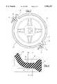
- FIG. 2is a top view of the brake actuator shown in FIG. 1 illustrating a clamp band having two retaining bolts;
- FIG. 3is a cross-sectional side elevational view of a preferred embodiment of the diaphragm of the present invention.
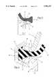
- FIG. 4is an enlarged view of the rim portion of the diaphragm as shown in FIG. 3;
- FIG. 5is a cross-sectional view of the rim portion of the diaphragm resting on a flange portion of the service housing;
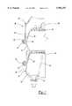
- FIG. 6is a cross-sectional side elevational view of the rim portion of the diaphragm disposed within the service chamber assembly including a clamp ring;
- FIG. 7is a partial cross-sectional side elevational view of an alternative embodiment of the brake actuator of the present invention.
- a brake actuator 20is shown generally, illustrated here as a single-diaphragm air brake actuator.
- the brake actuator 20includes a service chamber assembly 22 having a push rod 24 attached to a service side piston 26.
- the service chamber assembly 22includes a service housing 30 and a service housing cover 32 which define a non-pressure chamber 28 which encloses a return spring 36.
- Conventional mounting bolts 34 and a yoke assembly 35are also shown.
- Other brake actuator assembliesmay be suitable in the present invention.
- fluid actuated or "air brakes” of this natureare controlled by the movement of one or more flexible diaphragms and rigid piston plates which combine to form a movable wall when actuated by air pressure differentials created in the various chambers of the brake actuator 20.
- the brake actuator 20is equipped with a flexible, cup-shaped, and generally circular diaphragm 40 having a peripheral annular flange 41 including an expanded outside diameter portion or simply expanded portion 42 in the nature of an integral O-ring or the like.
- the diaphragm 40forms a hermetic or air-tight seal by the compression of the expanded portion 42 at the interface of the service housing 30 and the service housing cover 32.
- the diaphragm 40is formed of a resilient material such as rubber, neoprene, fabric-center reinforced neoprene or the like.
- a clamp ring 44is positioned over an annular flange portion 31 of the service housing 30 and an annular flange portion of the service housing cover 32.
- the clamp ring 44is shown in greater detail having two semi-circular portions 50 and 52.
- Each semi-circular portion 50,52having tabs or ears 54 through which clamp retaining bolts 56 are inserted to tighten the clamp ring 44 in position by tightening retaining nuts 58 on the clamp retaining bolts 56. That is, the clamp ring 44 secures the service housing 30 to the service housing cover 32 and compresses the expanded portion 42 of the diaphragm 40 forming an air-tight seal.
- a one-piece, single-bolt clamp of this typeis also well known in the art and can be utilized with the present invention.
- the diaphragm 40is shown in greater detail.
- the diaphragm 40is generally cup-shaped and includes an annular radial flange 41 having an expanded portion 42 and co-axially disposed flats 43 located adjacent to the expanded wedge-shaped portion 42.
- the expanded portion 42 of the annular flange 41is generally wedge-shaped at its outer portion. Adjacent to the wedge-shaped expanded portion 42 of the annular flange 41 are disposed co-axially aligned flat portions 43 on opposite sides of the annular flange 41.
- the flats 43preferably have a minimum flat radius or width of approximately 0.030 inches but may be as large as necessary depending upon the dimensions of the diaphragm. Preferably, the width of the flat 43 ranges from approximately 0.030 inches to approximately 0.075 inches.
- the flats 43allow the diaphragm 40 to be more easily and accurately seated between the radial flanges 31 and 33.
- the annular flange 41 of the diaphragm 40is shown seated on the radial flange 31 of the service housing 30.
- the opposed flanges 31,33 of the service housing 30 and the service housing cover 32, respectivelyare U-shaped in cross-section opening outwardly.
- the opposed flanges 31 and 33include a flange engagement portion 38 which engages the flat portions 43 on the annular flange 41.
- the U-shaped flange portions 31 and 33engage the flats 43 of the annular flange 41 at the apogees of the U-shaped region.
- Each radial flange 31 and 33also includes an outer leg 39 which receives and compresses the wedge-shaped expanded portion 42 of the diaphragm 40 during applications of the clamp ring 44.
- the diaphragm 40is shown disposed between the annular flanges 31 and 33 including the clamp ring 44 disposed thereon.
- the flats 43 of the annular flange 41are disposed directly adjacent to the flange engagement portion 38 or apogees of the flanges 31 and 33.
- the wedge-shaped expanded portion 42 of the annular flange 41is received and compressed by the outer legs 39 of the radial flanges 31 and 33 to fill a generally U-shaped space 45 between the clamp band 44 and the housing members 30 and 32 as shown in FIG. 6.
- the wedge-shaped expanded portion 42is compressed to such a degree that it completely fills the space 45 between the clamp band 44 and the housing members 30 and 32 to form a "hydraulic lock."
- the hydraulic lockreduces the incidence of brake actuator 20 leakage and also reduces creep or "run-out" of the diaphragm 40 which is a particular problem when the diaphragm 40 is not accurately aligned during assembly.
- the flexible diaphragm 40 of this inventionwill thus naturally and accurately seat the flat 43 on the apogee of the U-shaped flange 31 of the service housing 30, even when the diaphragm 40 is initially ovoid when received from the molder. Therefore, the person assembling the diaphragm 40 on the service housing 30 does not have to adjust the location of the diaphragm 40 on the service housing 30 or hold the diaphragm 40 in place during assembly of the cover 32.
- the U-shaped flange 33 of the cover 32will naturally nest and accurately seat on the opposed flat 43 on the diaphragm rim portion 41 prior to receipt of the clamp ring 44, resulting in a very accurate alignment of the service housing 30, diaphragm 40, and cover 32 which is very important to avoid leakage around the diaphragm 40 following assembly.
- the accuracy of the alignmentis not likely to be disturbed or displaced during clamping of the flanges 31,33 because the components are nested and are therefore not easily displaced.
- the wedge-shaped portion 42 of the outer flange 41can be engaged by the U-shaped flanges 31 and 33 to align the diaphragm 40. If the diaphragm 40 is not completely aligned, more of the wedge-shaped portion 42 will be squeezed out at that point creating an adequate seal and essentially self-align the diaphragm 40 between the U-shaped flanges 31 and 33.
- Another feature of the diaphragm 40 of the present inventionis that by reducing the thickness of the annular flange portion 41 at the flats 43, the clamp band 44 is more easily assembled on the housing 30 and housing cover 32 without the necessity for compressing together the housing 30, diaphragm 40, and housing cover 32 prior to applying the clamp band 44.
- the clamp band 44will compress the annular flange portion 41 of the diaphragm 40 as the clamp retaining bolts 56 of the clamp band 44 are tightened.
- a double diaphragm brake actuator assembly 80is shown generally. Like elements are designated using the same reference numerals as in the embodiment shown in FIGS. 1 through 6. Also, it is to be understood that while the present invention is described in connection with a specific type of brake actuator and has been illustrated with reference to both a single diaphragm brake actuator and a double diaphragm brake actuator, other fluid brake actuators may be made in accordance with the present invention such as piston type brake actuators, without regard to the type of brakes, cam, disc, or wedge, actuated by the brake actuator and with or without external tube breather systems.
- the present inventionis adaptable to virtually any brake actuator wherein a diaphragm is compressed between a first housing and housing cover or a service housing and a flange case or the like and all of these devices are intended to come within the scope of the present invention.
- the double diaphragm air brake actuator 80includes a service chamber assembly 22 and a spring chamber assembly 82.
- the spring chamber assembly 82includes a spring side diaphragm 86 having an expanded portion 88 which is in the nature of an integral O-ring or the like.
- a spring side piston 90 and a power spring 92are disposed within the spring chamber assembly 82.
- An annular retaining member 83 disposed on the spring chamber assembly 82provides a tamper-resistant closure or attachment of the head 85 of the spring chamber assembly 82 to the flange case 84.
- the retaining member 83 in this embodimentis in the nature of a circular channel clamp which receives flange 94 thereby causing the compression of the expanded portion 88 of the diaphragm 86.
Landscapes
- Engineering & Computer Science (AREA)
- General Engineering & Computer Science (AREA)
- Mechanical Engineering (AREA)
- Braking Arrangements (AREA)
- Diaphragms And Bellows (AREA)
- Diaphragms For Electromechanical Transducers (AREA)
- Actuator (AREA)
- Preparing Plates And Mask In Photomechanical Process (AREA)
- Separation Using Semi-Permeable Membranes (AREA)
- Audible-Bandwidth Dynamoelectric Transducers Other Than Pickups (AREA)
- Piezo-Electric Or Mechanical Vibrators, Or Delay Or Filter Circuits (AREA)
Abstract
Description
Claims (15)
Priority Applications (11)
| Application Number | Priority Date | Filing Date | Title |
|---|---|---|---|
| US09/087,523US5992297A (en) | 1998-05-29 | 1998-05-29 | Easy fit diaphragm |
| DE69912121TDE69912121T2 (en) | 1998-05-29 | 1999-05-12 | EASY TO INSTALL MEMBRANE |
| DK99922936TDK1082519T3 (en) | 1998-05-29 | 1999-05-12 | Brake diaphragm for easy mounting |
| AT99922936TATE252199T1 (en) | 1998-05-29 | 1999-05-12 | EASY TO INSTALL MEMBRANE |
| JP2000552380AJP2002517674A (en) | 1998-05-29 | 1999-05-12 | Diaphragm for easy installation |
| ES99922936TES2209437T3 (en) | 1998-05-29 | 1999-05-12 | EASY ASSEMBLY DIAPHRAGM. |
| BR9911209-4ABR9911209A (en) | 1998-05-29 | 1999-05-12 | Brake driver and diaphragm flexibly for a brake driver |
| PT99922936TPT1082519E (en) | 1998-05-29 | 1999-05-12 | DIAPHRAGM OF EASY MOUNTING |
| EP99922936AEP1082519B1 (en) | 1998-05-29 | 1999-05-12 | Easy fit diaphragm |
| PCT/US1999/010340WO1999063203A1 (en) | 1998-05-29 | 1999-05-12 | Easy fit diaphragm |
| CA002333012ACA2333012A1 (en) | 1998-05-29 | 1999-05-12 | Easy fit diaphragm |
Applications Claiming Priority (1)
| Application Number | Priority Date | Filing Date | Title |
|---|---|---|---|
| US09/087,523US5992297A (en) | 1998-05-29 | 1998-05-29 | Easy fit diaphragm |
Publications (1)
| Publication Number | Publication Date |
|---|---|
| US5992297Atrue US5992297A (en) | 1999-11-30 |
Family
ID=22205684
Family Applications (1)
| Application Number | Title | Priority Date | Filing Date |
|---|---|---|---|
| US09/087,523Expired - LifetimeUS5992297A (en) | 1998-05-29 | 1998-05-29 | Easy fit diaphragm |
Country Status (11)
| Country | Link |
|---|---|
| US (1) | US5992297A (en) |
| EP (1) | EP1082519B1 (en) |
| JP (1) | JP2002517674A (en) |
| AT (1) | ATE252199T1 (en) |
| BR (1) | BR9911209A (en) |
| CA (1) | CA2333012A1 (en) |
| DE (1) | DE69912121T2 (en) |
| DK (1) | DK1082519T3 (en) |
| ES (1) | ES2209437T3 (en) |
| PT (1) | PT1082519E (en) |
| WO (1) | WO1999063203A1 (en) |
Cited By (14)
| Publication number | Priority date | Publication date | Assignee | Title |
|---|---|---|---|---|
| US6349629B1 (en) | 2000-08-25 | 2002-02-26 | Indian Head Industries, Inc. | Brake actuator |
| US6526866B2 (en) | 2001-04-09 | 2003-03-04 | Haldex Brake Corporation | Radial sealed air brake chamber |
| US6722262B2 (en) | 2002-03-06 | 2004-04-20 | Honeywell International, Inc. | Pneumatic actuator with a nested diaphragm assembly |
| US20050092173A1 (en)* | 2003-10-30 | 2005-05-05 | Metro Bearing & Automotive Limited | Safety device for spring brakes |
| US6988442B2 (en) | 2001-12-20 | 2006-01-24 | Haldex Brake Corporation | Air brake diaphragms which resist pull-out |
| US20070017757A1 (en)* | 2005-07-20 | 2007-01-25 | Frank Schrader | Spring-actuated brake cylinder |
| US20080041672A1 (en)* | 2006-08-17 | 2008-02-21 | Tse Brakes, Inc. | Reduced profile air brake actuator |
| US20100224806A1 (en)* | 2007-08-29 | 2010-09-09 | Keihin Corporation | Pressure-reducing valve |
| US20120006192A1 (en)* | 2010-07-07 | 2012-01-12 | Rhoads David C | Adhesive Attachment Of The Disc Brake Pushrod Plate To The Diaphragm |
| US20120248364A1 (en)* | 2011-03-31 | 2012-10-04 | Buerkert Werke Gmbh | Membrane valve |
| US20140326127A1 (en)* | 2013-05-02 | 2014-11-06 | Bendix Commerical Vehicle Systems, Llc | Spring Brake Actuator and Method for Making a Spring Brake Actuator |
| EP1752230B2 (en)† | 2005-08-12 | 2015-03-11 | United Technologies Corporation | Method of repairing a gas turbine engine part |
| US11209058B2 (en) | 2019-11-19 | 2021-12-28 | Tse Brakes, Inc. | Spring brake actuator |
| US20220065257A1 (en)* | 2018-12-04 | 2022-03-03 | Intex Industries Xiamen Co. Ltd | Inflatable product with integrated air pump |
Families Citing this family (1)
| Publication number | Priority date | Publication date | Assignee | Title |
|---|---|---|---|---|
| DE102008007203A1 (en)* | 2008-02-01 | 2009-08-06 | Robert Bosch Gmbh | Compact injection device with pressure-controlled nozzle |
Citations (1)
| Publication number | Priority date | Publication date | Assignee | Title |
|---|---|---|---|---|
| US4960036A (en)* | 1987-11-06 | 1990-10-02 | Indian Head Industries, Inc. | Tamper-resistant brake actuator |
Family Cites Families (10)
| Publication number | Priority date | Publication date | Assignee | Title |
|---|---|---|---|---|
| US3424064A (en)* | 1966-03-14 | 1969-01-28 | Bendix Westinghouse Automotive | Clamp type rotochamber |
| SU638787A1 (en)* | 1976-12-10 | 1978-12-25 | Государственный Ордена Трудового Красного Знамени Строительный Трест "Алтайсвинецстрой" | Diaphragm chamber |
| GB1533546A (en)* | 1977-08-31 | 1978-11-29 | Ford Motor Co | Air hydraulic brake actuator |
| US5205205A (en)* | 1987-11-06 | 1993-04-27 | Indian Head Industries, Inc. | Tamper resistant brake actuator |
| KR930002779B1 (en)* | 1987-11-09 | 1993-04-10 | 미쓰비시전기주식회사 | Diaphragm Device |
| US5193432A (en)* | 1992-04-29 | 1993-03-16 | Anchorlok Corp. | Tamper-resistant brake actuator |
| US5285716A (en)* | 1992-09-22 | 1994-02-15 | Tse Brakes, Inc. | Spring brake assembly having tamper-resistant welded housing and method for making same |
| US5315918A (en)* | 1993-02-19 | 1994-05-31 | Nai Anchorlok, Inc. | Tamper-resistant brake actuator |
| US5758564A (en)* | 1996-06-13 | 1998-06-02 | Tse Brakes, Inc. | Brake actuator and method of manufacture |
| US5765466A (en)* | 1997-01-24 | 1998-06-16 | Indian Head Industries | Brake actuator with self-centering diaphram |
- 1998
- 1998-05-29USUS09/087,523patent/US5992297A/ennot_activeExpired - Lifetime
- 1999
- 1999-05-12CACA002333012Apatent/CA2333012A1/ennot_activeAbandoned
- 1999-05-12BRBR9911209-4Apatent/BR9911209A/ennot_activeIP Right Cessation
- 1999-05-12WOPCT/US1999/010340patent/WO1999063203A1/enactiveIP Right Grant
- 1999-05-12EPEP99922936Apatent/EP1082519B1/ennot_activeExpired - Lifetime
- 1999-05-12PTPT99922936Tpatent/PT1082519E/enunknown
- 1999-05-12JPJP2000552380Apatent/JP2002517674A/enactivePending
- 1999-05-12DKDK99922936Tpatent/DK1082519T3/enactive
- 1999-05-12DEDE69912121Tpatent/DE69912121T2/ennot_activeExpired - Lifetime
- 1999-05-12ATAT99922936Tpatent/ATE252199T1/ennot_activeIP Right Cessation
- 1999-05-12ESES99922936Tpatent/ES2209437T3/ennot_activeExpired - Lifetime
Patent Citations (1)
| Publication number | Priority date | Publication date | Assignee | Title |
|---|---|---|---|---|
| US4960036A (en)* | 1987-11-06 | 1990-10-02 | Indian Head Industries, Inc. | Tamper-resistant brake actuator |
Cited By (22)
| Publication number | Priority date | Publication date | Assignee | Title |
|---|---|---|---|---|
| US6349629B1 (en) | 2000-08-25 | 2002-02-26 | Indian Head Industries, Inc. | Brake actuator |
| US6526866B2 (en) | 2001-04-09 | 2003-03-04 | Haldex Brake Corporation | Radial sealed air brake chamber |
| US6988442B2 (en) | 2001-12-20 | 2006-01-24 | Haldex Brake Corporation | Air brake diaphragms which resist pull-out |
| US6722262B2 (en) | 2002-03-06 | 2004-04-20 | Honeywell International, Inc. | Pneumatic actuator with a nested diaphragm assembly |
| US20050092173A1 (en)* | 2003-10-30 | 2005-05-05 | Metro Bearing & Automotive Limited | Safety device for spring brakes |
| US6899015B2 (en)* | 2003-10-30 | 2005-05-31 | Metro Bearing & Automotive Limited | Safety device for spring brakes |
| US20070017757A1 (en)* | 2005-07-20 | 2007-01-25 | Frank Schrader | Spring-actuated brake cylinder |
| EP1752230B2 (en)† | 2005-08-12 | 2015-03-11 | United Technologies Corporation | Method of repairing a gas turbine engine part |
| US20080041672A1 (en)* | 2006-08-17 | 2008-02-21 | Tse Brakes, Inc. | Reduced profile air brake actuator |
| US8522666B2 (en) | 2006-08-17 | 2013-09-03 | Tse Brakes, Inc. | Reduced profile air brake actuator |
| US20100224806A1 (en)* | 2007-08-29 | 2010-09-09 | Keihin Corporation | Pressure-reducing valve |
| US8408515B2 (en)* | 2007-08-29 | 2013-04-02 | Keihin Corporation | Pressure-reducing valve |
| US20120006192A1 (en)* | 2010-07-07 | 2012-01-12 | Rhoads David C | Adhesive Attachment Of The Disc Brake Pushrod Plate To The Diaphragm |
| US10626939B2 (en)* | 2010-07-07 | 2020-04-21 | Haldex Brake Products Corporation | Adhesive attachment of the disc brake pushrod plate to the diaphragm |
| US20120248364A1 (en)* | 2011-03-31 | 2012-10-04 | Buerkert Werke Gmbh | Membrane valve |
| US9010729B2 (en)* | 2011-03-31 | 2015-04-21 | Buerkert Werke Gmbh | Membrane valve |
| US9546700B2 (en)* | 2013-05-02 | 2017-01-17 | Bendix Commercial Vehicle Systems Llc | Spring brake actuator and method for making a spring brake actuator |
| US20140326127A1 (en)* | 2013-05-02 | 2014-11-06 | Bendix Commerical Vehicle Systems, Llc | Spring Brake Actuator and Method for Making a Spring Brake Actuator |
| US20220065257A1 (en)* | 2018-12-04 | 2022-03-03 | Intex Industries Xiamen Co. Ltd | Inflatable product with integrated air pump |
| US11994139B2 (en)* | 2018-12-04 | 2024-05-28 | Intex Marketing Ltd. | Inflatable product with integrated air pump |
| US11209058B2 (en) | 2019-11-19 | 2021-12-28 | Tse Brakes, Inc. | Spring brake actuator |
| US11608866B2 (en) | 2019-11-19 | 2023-03-21 | Tse Brakes, Inc. | Spring brake actuator |
Also Published As
| Publication number | Publication date |
|---|---|
| DE69912121D1 (en) | 2003-11-20 |
| EP1082519A1 (en) | 2001-03-14 |
| BR9911209A (en) | 2001-10-09 |
| DE69912121T2 (en) | 2004-07-22 |
| CA2333012A1 (en) | 1999-12-09 |
| WO1999063203A1 (en) | 1999-12-09 |
| DK1082519T3 (en) | 2004-02-16 |
| ES2209437T3 (en) | 2004-06-16 |
| EP1082519A4 (en) | 2002-07-10 |
| ATE252199T1 (en) | 2003-11-15 |
| JP2002517674A (en) | 2002-06-18 |
| PT1082519E (en) | 2004-03-31 |
| EP1082519B1 (en) | 2003-10-15 |
Similar Documents
| Publication | Publication Date | Title |
|---|---|---|
| US5992297A (en) | Easy fit diaphragm | |
| AU648589B2 (en) | A tamper-resistant brake actuator and a method of forming a tamper-resistant brake actuator | |
| US5067391A (en) | Tamper-resistant brake actuator | |
| US5353688A (en) | Tamper-resistant brake actuator | |
| CA2420230C (en) | Improved brake actuator | |
| US5263403A (en) | Method of forming a tamper-resistant brake actuator | |
| US6526866B2 (en) | Radial sealed air brake chamber | |
| US5205205A (en) | Tamper resistant brake actuator | |
| US5433138A (en) | Tamper-resistant brake actuator | |
| AU2002307228A1 (en) | Radial sealed air brake chamber | |
| US5765466A (en) | Brake actuator with self-centering diaphram | |
| US5676036A (en) | Small envelope tamper-resistant spring brake actuator | |
| EP1889768A2 (en) | Reduced profile brake actuator | |
| US6988442B2 (en) | Air brake diaphragms which resist pull-out | |
| US6223647B1 (en) | Brake actuator and method of forming same | |
| US6357337B1 (en) | Spring brake actuator with sealed chamber and method for sealing | |
| MXPA00011588A (en) | Easy fit diaphragm | |
| EP4173911B1 (en) | Diaphragm brake cylinder with reduction ring integrated in the diaphragm | |
| KR950010183Y1 (en) | Tamper-resistant brake actuator |
Legal Events
| Date | Code | Title | Description |
|---|---|---|---|
| AS | Assignment | Owner name:INDIAN HEAD INDUSTRIES, INC., NORTH CAROLINA Free format text:ASSIGNMENT OF ASSIGNORS INTEREST;ASSIGNORS:PLANTAN, RONALD;HOLM, MICHAEL M.;REEL/FRAME:009290/0256 Effective date:19980608 | |
| STCF | Information on status: patent grant | Free format text:PATENTED CASE | |
| AS | Assignment | Owner name:BANK OF AMERICA, N.A., GEORGIA Free format text:SECURITY INTEREST;ASSIGNOR:INDIAN HEAD INDUSTRIES, INC.;REEL/FRAME:010766/0967 Effective date:20000329 | |
| FEPP | Fee payment procedure | Free format text:PAT HOLDER CLAIMS SMALL ENTITY STATUS, ENTITY STATUS SET TO SMALL (ORIGINAL EVENT CODE: LTOS); ENTITY STATUS OF PATENT OWNER: SMALL ENTITY | |
| FPAY | Fee payment | Year of fee payment:4 | |
| FPAY | Fee payment | Year of fee payment:8 | |
| AS | Assignment | Owner name:INDIAN HEAD INDUSTRIES, INC., NORTH CAROLINA Free format text:RELEASE BY SECURED PARTY;ASSIGNORS:BANK OF AMERICA, N.A.;COMERICA BANK;REEL/FRAME:019331/0733 Effective date:20070511 | |
| FPAY | Fee payment | Year of fee payment:12 |