US5991885A - Method and apparatus for detecting the presence of a remote device and providing power thereto - Google Patents
Method and apparatus for detecting the presence of a remote device and providing power theretoDownload PDFInfo
- Publication number
- US5991885A US5991885AUS08/872,977US87297797AUS5991885AUS 5991885 AUS5991885 AUS 5991885AUS 87297797 AUS87297797 AUS 87297797AUS 5991885 AUS5991885 AUS 5991885A
- Authority
- US
- United States
- Prior art keywords
- signal
- protocol
- electrical power
- coupled
- network
- Prior art date
- Legal status (The legal status is an assumption and is not a legal conclusion. Google has not performed a legal analysis and makes no representation as to the accuracy of the status listed.)
- Expired - Lifetime
Links
Images


Classifications
- G—PHYSICS
- G06—COMPUTING OR CALCULATING; COUNTING
- G06F—ELECTRIC DIGITAL DATA PROCESSING
- G06F1/00—Details not covered by groups G06F3/00 - G06F13/00 and G06F21/00
- G06F1/26—Power supply means, e.g. regulation thereof
- H—ELECTRICITY
- H04—ELECTRIC COMMUNICATION TECHNIQUE
- H04L—TRANSMISSION OF DIGITAL INFORMATION, e.g. TELEGRAPHIC COMMUNICATION
- H04L69/00—Network arrangements, protocols or services independent of the application payload and not provided for in the other groups of this subclass
- H04L69/08—Protocols for interworking; Protocol conversion
- H—ELECTRICITY
- H04—ELECTRIC COMMUNICATION TECHNIQUE
- H04L—TRANSMISSION OF DIGITAL INFORMATION, e.g. TELEGRAPHIC COMMUNICATION
- H04L9/00—Cryptographic mechanisms or cryptographic arrangements for secret or secure communications; Network security protocols
- H04L9/40—Network security protocols
Definitions
- This inventionrelates to networking systems, and more particularly, to network hubs and network interface adapters for automatically and continuously detecting the presence of a remote adapter coupled to a network twisted-pair cable, providing electrical power from a network hub to the remote adapter via the network twisted-pair cable, creating a multi-protocol networking system, and automatically connecting the remote adapter to the appropriate network hub.
- PCMCIAPersonal Computer Memory Card International Association
- the computer networkincludes a protocol conversion bridge that converts communicated data between an infrared protocol and a protocol of the computer network.
- the protocol conversion bridgeis coupled to a connector typically near the user's work station. The connector is then coupled to a network hub that is centrally located.
- a dedicated electrical power supply located near the bridge and the infrared transceiverprovides electrical power to the protocol conversion bridge. The dedicated electrical power supply increases the system cost and requires an AC electrical power outlet.
- U.S. Pat. No. 5,444,184describes a system that transmits both electrical power and low baud rate signals over the same twisted-pair wires.
- An attachment unit interface (AUI) in LAN applicationsuses dedicated wires in a cable to provide electrical power from a data terminal equipment (DTE) to an external medium attachment unit (MAU) which could be 50 meters away from the DTE. All of these systems simply provide electrical power over the wires. None of these systems checks or confirms the type of system connected thereto before supplying the electrical power.
- DTEdata terminal equipment
- MAUmedium attachment unit
- Standard network protocolsmay be described in an Open System Interconnection (OSI) interface standard.
- OSIOpen System Interconnection
- One standard network protocolis the Ethernet which is described in IEEE standard 802.3 CSMA/CD, the subject matter of which is incorporated by reference in its entirety.
- Another standard network protocolis the Token Ring protocol which is described in ANSI/IEEE standard 802.5, the subject matter of which is incorporated by reference in its entirety.
- Both of these IEEE standardsdescribe the media access control (MAC) layer and the physical layer of the OSI interface.
- MACmedia access control
- FIG. 1is a pictorial view of the interface layers of the OSI standard. For simplicity, layer 3 through layer 7 of the OSI are combined as higher layers 139.
- Layer 2 of the OSI interfacecomprises the data link control (DLC) which includes a logical link control (LLC) layer 138 and a media access control (MAC) layer 134.
- Physical layer 1 of the OSI interfacecomprises several sublayers including an attachment unit interface (AUI). The AUI is specified for a 10 Mb/s Ethernet but not for a 100 Mb/s Ethernet.
- a media attachment unit (MAU) 142includes all of the physical sublayers other than signaling and coding sublayer. In a twisted-pair cable, the medium dependent interface MDI 144 is an RJ45 connector.
- U.S. Pat. No. 5,497,460discloses a detection mechanism that allows two different media access control layer protocols (Ethernet and Token Ring) to share the same connector and medium in the OSI model of FIG. 1.
- the detection schemerequires a sophisticated processing unit that issues a protocol dependent MAC frame and physical signals and compares a predefined status in memory to determine which one of the two presumed protocols runs on the twisted-pair cable.
- the detection schemecannot communicate with any device which does not conform with Ethernet or Token Ring.
- U.S. Pat. No. 5,410,535describes a device that differentiates between mediums that the device is connected to so that the connected devices may share the same connector.
- the mediumin this case could be a twisted-pair cable or AUI for other medium types.
- the control flow and logic manufactured in siliconare Ethernet physical layer dependent.
- U.S. Pat. No. 5,541,957includes a separate physical layer logic to allow two Ethernet connections operating at different transfer rates to share the same connector.
- U.S. Pat. No. 5,121,482describes a device that detects the connected device independent of networking protocol. But its detection mechanism relies on the impedance of the data signal lines, its detection circuitry is also coupled directly to the data signal line, which may lead to interference or even corruption on the communication link when running the detection procedure.
- the present inventionprovides a detection circuit for detecting the presence of a remote device, which may or may not be a network device.
- the present inventionprovides a system for controlling the application of electrical power to a detected device.
- the systemincludes a signal generator and a feedback analyzer.
- the signal generatorreceives a timing signal, a control signal, and a select signal.
- the signal generatorprovides a presence request signal in response to the select signal being in a first logic state and provides the control signal in response to the select signal being in a second logic state.
- the feedback analyzeris coupled to the detected device and provides a presence signal in response to the presence signal detected from the coupled device being of a predetermined type and being coupled to the output of the signal generator.
- the feedback analyzerprovides the select signal in a second logic state when such a device is detected and provides the select signal of a first logic state when such a device is not detected.
- the feedback analyzercontrols the application of electrical power to the coupled device of a predetermined type in response to the present signal.
- the present inventionprovides a method for applying electrical power.
- a first deviceis an initiator and applies a symmetric bipolar signal to a second device.
- a feedback signal from the second devicebased upon the signal supplied by the first device at the first detection time, triggers a comparator and indicates the successful connection of the second device to the first device.
- the second devicemay provide the feedback signal based on another electrical power source and not based on the symmetric bipolar signal.
- the first devicesupplies a current limited electrical power to the second device.
- the second deviceuses the electrical power gained from the first device to sustain its own operation also use it to derive the feedback signal to replace the original signal that is provided by the first device.
- the first deviceis freed to remove the applied signal state in the first detection time, and use the same line for other purpose.
- the present inventionprovides a network system that includes a plurality of user interface connectors and first and second network hubs. Each of the plurality of user interface connectors is adapted for coupling to a remote device.
- the first network hubcommunicates on a first operational protocol.
- the second network hubis coupled to the plurality of user interface connectors for communicating data between devices coupled thereto and is coupled to the first network hub.
- the second network hubidentifies the operational protocol of a coupled device. When the identified operational protocol of the coupled device is a first operational protocol, the second network hub communicates data between the first and second network hubs.
- the second network hubcommunicates with said coupled device in a second operational protocol and identifies the presence of an adapter of a first type coupled to at least one of the plurality of user interface connectors and continuously provides electrical power to the adapter in response to the identified presence of the adapter.
- the second network hubstops providing electrical power to the adapter in response to no identified presence of the adapter.
- FIG. 1is a pictorial view illustrating the interface layers of the open system interconnection model.
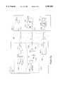
- FIG. 2is a block diagram illustrating a network system in accordance with the present invention.
- FIG. 3is a block diagram illustrating a network system in accordance with another embodiment of the present invention.
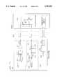
- FIG. 4ais block diagram illustrating the network hub of the network system of FIG. 2 in accordance of the present invention.
- FIG. 4bis a block diagram illustrating a network hub of the network system of FIG. 3 in accordance with another embodiment of the present invention.
- FIG. 5ais a schematic diagram illustrating a conventional 10Base-T twisted-pair cable connection.
- FIG. 5bis a schematic diagram illustrating a conventional 100Base-TX twisted-pair cable connection.
- FIG. 5cis a schematic diagram illustrating a conventional Token Ring twisted-pair cable connection.
- FIG. 6ais a schematic diagram illustrating a device presence detector that is coupled to a remote adapter of a first type in accordance with the present invention.
- FIG. 6bis a schematic diagram illustrating a device presence detector coupled to a remote adapter of a second type in accordance with the present invention.
- FIG. 6cis a schematic diagram illustrating a device presence detector coupled to a remote adapter of a third type in accordance with the present invention.
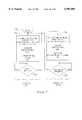
- FIG. 7is a flow diagram illustrating the operation of the device presence detector of FIGS. 6a-6c in accordance with the present invention.
- the methods and systems of the present inventioninstantly and continuously detect the connection status during idle or normal operation of the systems.
- the systemwithout the presence of a detected network adapter, assumes a connected device uses a specific protocol, such as Ethernet or Token Ring.
- the network systemis configured for an infrared (IR) adapter or Ethernet and not Token Ring.
- IRinfrared
- a user connector of the systemfunctions with either an IR adapter or an Ethernet adapter.
- the network systemis configured for an IR adapter or Token Ring, and not for Ethernet.
- a user connector of the systemfunctions with either an IR adapter or a Token Ring adapter.
- the network systemis configured for an IR adapter, Token Ring, and Ethernet.
- the network hub 202 (FIG. 2) and the network hub 302 (FIG. 3) of the present inventionprovide the electrical power to the detected device when the presence of the detected device is confirmed, and does not provide electrical power to the connector and the twisted-pair cable when either adapters of another type (such as Ethernet 10Base-T, 100Base-TX 100Base-T4, and Token Ring adapters) are connected or when no adapter is connected. Since the detected device receives the electrical power from the detecting device, a separate costly electrical power supply is not needed. The systems of the present invention reduce cost, and eliminate the massive interconnection wires and the electrical power plug in the office.
- adapters of another typesuch as Ethernet 10Base-T, 100Base-TX 100Base-T4, and Token Ring adapters
- FIG. 2is a block diagram illustrating a network system 200 in accordance with the present invention.
- the network system 200includes a network 201 and a plurality of computers 212. For clarity, only three computers, 212-1 through 212-3, are shown.
- the computers 212may be, for example, workstations, portable computers, desktop PCs, or personal digital assistants (PDA).
- PDApersonal digital assistants
- the network 201includes a network hub 202, a plurality of twisted-pair cables 205, a plurality of user interface connectors 204, and an infrared adapter 206.
- a network hub 202For simplicity and clarity, only four twisted-pair cables 205 and four user interface connectors 204 are shown. Also, for clarity, only one infrared adapter 206 is shown.
- the network 201may include other numbers of network hubs 202, hub user connectors 208, twisted-pair cables 205, user interface connectors 204, and infrared adapters 206.
- the network hub 202includes a plurality of hub user connectors 208 and an up-link connector 210.
- the up-link connector 210allows the network 201 to be connected to another network (not shown).
- the computer 212-1includes a first interface 214 which is an infrared transceiver.
- the computer 212-1communicates in a first protocol via the infrared transceiver 214 with the infrared adapter 206.
- the first protocolis an infrared protocol.
- the computers 212-2 and 212-3each include a second computer interface 216 that communicates in a second protocol.
- the protocol of the computer interface 216is a 10Base-T or 100Base-TX protocol.
- the protocol of the computer interface 216is a Token Ring protocol.
- the user interface connectors 204are conventional RJ45 connectors.
- the computers 212-2 and 212-3may be physically connected to the network 201 via the hub user connectors 208 by physical wire connections, such as twisted-pair wires, between the respective second computer interfaces 216 and the user interface connectors 204.
- the twisted-pair cableaccording to one embodiment of the present invention may be conventional category 3 or 5 twisted-pair cable.
- the wiremay be disconnected at the computer 212-2 or 212-3 to allow the user to have portability of the associated computer 212.
- the network 201communicates with the plurality of computers 212 via the user interface connectors 204, using the infrared adapter 206 for wireless communication or using the computer interfaces 216 for wired communication.
- the computer 212-1communicates without wire and instead uses an infrared signal 215 communicated between the IR adapter 206 and the IR transceiver 214 of the computer 212-1 to communicate with the network 201.
- the plurality of computers 212may communicate with each other via the hub user connectors 208 or communicate with another network via the up-link connector 210.
- the network 201is a Local Area Network (LAN) and may link to other networks.
- LANLocal Area Network
- the network 201recognizes the protocol of computers 212 coupled to the network hub 202 and communicates with the computer 212 in the appropriate protocol.
- the network 201provides electrical power to an IR adapter 206 when the IR adapter 206 is coupled to the network hub 202, but does not provide electrical power for other adapter for other protocols. If the network 201 determines that another type of device other than an IR adapter 206 is coupled to a user interface connector 204, the network 201 does not apply electrical power.
- the network system 200provides wireless communication between computers 212 and the network 201.
- the adapter 206is described herein as operating with infrared, the adapter 206 may provide wireless coupling other than infrared, such as radio frequency. In such a case, the network system 200 may be modified to operate with these other means of wireless coupling or combinations thereof.
- the network hub 202determines whether a remote device is connected to the user interface connectors 204 and determines the type of the remote device. If an infrared adapter 206 is connected to a user interface connector 204, the network hub 202 provides electrical power to the IR adapter 206 in response to such detection, and stops providing electrical power to the IR adapter 206 in response to no detection of the IR adapter 206.
- a usermay place a computer 212-1 in the vicinity of the IR adapter 206 and communicate with the network 201.
- the IR adapter 206provides bi-directional communication between the network hub 202 and an IR transceiver 214 of the computer 212-1.
- the network hub 202converts data from an IR protocol to the protocol of the network and vice versa.
- the network hub 202also converts data from the protocol of either of the computers 212-2 or 212-3 into the protocol of the network and vice versa. Accordingly, the network hub 202 allows communication between any of the computers 212 by making the appropriate protocol conversion.
- FIG. 3is a block diagram illustrating a network system 300 in accordance with the present invention.
- the network system 300includes a network 301 and a plurality of computers 212. For clarity, only three computers 212-1 through 212-3 are shown.
- the computers 212-1 through 212-3include respective computer interfaces 214, 216, and 318.
- the computer interface 318communicates in a third protocol.
- the network 301includes a first network hub 302, a second network hub 303, an optional third network hub 304, a plurality of hub user connectors 204, and first and second pluralities of twisted-pair cables 205 and 305, respectively.
- the network 301may include additional network hubs.
- the network hub 302includes a plurality of hub user connectors 308, a plurality of pass-through connectors 309, and an up-link connector 310.
- the network hub 303includes a plurality of hub user connectors 320 and an up-link connector 322.
- the network hub 304includes a plurality of hub user connectors 324 and an up-link connector 326.
- the twisted-pair cables 305couple the pass-through connectors 309 of the network hub 302 to respective hub user connectors 320 of the network hub 303.
- twisted-pair cables 305couple the pass-through connectors 309 of the network hub 302 to respective hub user connectors 324 of the network hub 304.
- the network 301communicates with the computers 212 in a manner similar to that described above in conjunction with the network 201 of FIG. 2. However, communications within the network 301 differs from communication within the network 201. Specifically, the network hub 302 processes data in an infrared protocol and passes through data in other protocols to the network hubs 303 and 304 for processing.
- the first network hub 302determines whether an infrared adapter 206 is coupled to a user interface connector 204, and if such an IR adapter 206 is detected, the first network hub 302 converts the data between the protocol of the IR adapter 206 and the network hub 303 in a manner similar to that of the network hub 202 of FIG. 2. However, if an IR adapter 206 is not detected, the first network hub 302 couples the corresponding hub connector 308 to the corresponding pass-through connector 309 for communication with either the second hub 303 or the third hub 304. The network hub 302 does not process the data from the adapter. Hence, the first network hub 302 merely passes data communicated between the second network hub 303 or the third network hub 304 and the computer 212 without further processing.
- the network hub 302implements a "pass through" of network data to allow the system to use conventional network hub 303 and/or 304 to support a standard network protocol such as Ethernet and/or Token Ring.
- the network 301is coupled only to a computer that is in one of two protocols, for example, an infrared protocol and an Ethernet protocol.
- the present inventionallows a user using an existing network hub to establish a multiple protocol network system 301 for infrared communication, Ethernet and/or Token Ring. Multiple networking protocols share the same connector 204. Reusing existing conventional hubs and sharing the same connector reduces the system cost and increases the convenience of network access.
- FIG. 4ais a block diagram illustrating the network hub 202 in accordance with the present invention.
- the network hub 202includes a plurality of hub user connectors 208, an up-link connector 210, connection path 402, networking data path 404, detection path 406, first and second protocol handlers 408 and 410, respectively, networking data path 411 and 412, a plurality of device presence detectors 414, and select signal path 416.
- the networking data path 404couples the hub user connector 208 to a first terminal of the connection path 402.
- the detection path 406couples the device presence detector 414 to the hub user connector 208.
- the first and second protocol handlers 408 and 410are coupled to respective second and third terminals of the connection path 402.
- the networking data path 411couples the first and second protocol handlers 408 and 410.
- the networking data path 412couples the second protocol handler 410 to the up-link connector 210.
- the select signal path 416couples the device presence detector 414 to the connection path 402.
- the device presence detector 414provides a presence request signal on the detection path 406 which is applied to the hub user connector 208 for determining whether an infrared adapter 206 is coupled to the hub user connector 208. If an infrared adapter 206 is not coupled to the hub user connector 208, the device presence detector 414 applies a signal to the select signal path 416 that selectively couples the hub user connector 208 through the connection path 402 to the second protocol handler 410 which communicates with a computer 212 connected to hub user connector 208 in the second protocol. Communication with another network (not shown) by the second protocol handler 410 is via the up-link connector 210.
- the device presence detector 414provides a select signal on the select signal path 416 to couple the hub user connector 208 through the connection path 402 to the first protocol handler 408.
- the first protocol handler 408may communicate with another network (not shown) via the networking data paths 411 and 412, and the up-link connector 210.
- the first protocol handler 408performs the conversion between the first protocol and the second protocol, and also performs repeater or switching functions of the first protocol among the user connectors 208 with IR adapters 206.
- the second protocol handler 410performs repeater or switching functions of the second protocol among up-link connector, the first protocol handler 408, and user connectors 208, without IR adapters 206.
- Connection paths 402provide networking paths between the first protocol handler 408 and user connectors 208 with IR adapters 206, and the networking paths between the second protocol handler and user connectors 208 without IR adapters 206.
- Networking path 411allows both protocol handlers 408 and 410 to share the components for the up-link path.
- FIG. 4bis a block diagram illustrating the network hub 302 in accordance with the present invention.
- the network hub 302includes a plurality of hub user connectors 308, a plurality of pass-through connectors 309, an up-link connector 310, connection path 402, networking data path 404, detection path 406, protocol handler 408, a plurality of device presence detectors 414, select signal path 416 and networking data path 418.
- the networking data path 404couples the hub user connector 308 to a first terminal of the connection path 402.
- the detection path 406couples the device presence detector 414 to the hub user connector 308.
- the protocol handler 408is coupled to a second terminal of the connection path 402.
- the networking data path 418couples the protocol handler 408 to the up-link connector 310.
- the pass-through connector 309is coupled to a third terminal of the connection path 402.
- the select signal path 416couples the device presence detector 414 to the connection path 402.
- the device presence detector 414provides a presence request signal on the detection path 406 which is applied to the hub user connector 308 for determining whether an infrared adapter 206 is coupled to the hub user connector 308. If an infrared adapter 206 is not coupled to the hub user connector 308, the device presence detector 414 applies a select signal to the select signal path 416 that selectively couples the hub user connector 308 through the connection path 402 to the pass-through connector 309. This allows communication between a network hub 303 or 304 with a computer 212 coupled to the hub user interface connector 308. In this way, the network hub 302 merely passes data between the network hub 303 or 304 to the computer 212. Such communication is in the protocol of the network hub 303 or 304.
- the device presence detector 414provides a select signal on a select signal path 416 to couple the hub user connector 308 through the connection path 402 to the protocol handler 408.
- Communication between the network hub 302 and the computer 212is an infrared protocol.
- the protocol handler 408may communicate with another network (not shown) via the up-link connector 310.
- the protocol handler 408performs the conversion between the IR protocol and the second protocol, and also performs repeater or switching functions of the IR protocol among user connectors 208 with IR adapters 206.
- local-area network (LAN) applicationsthat include a twisted-pair cable as the media for data transfer typically use a standard RJ45 connector between components of the system, such as a networking port on PC, workstation, hub, bridge, or router.
- a standard RJ45 connectoris used with twisted-pair cable in Ethernet 10Base-T, 100Base-T, and Token Ring systems.
- the twisted-pair cablecontains 6 wires (3 pairs) or 8 wires (4 pairs).
- the LAN of these systemstypically follow the OSI physical layer standard of FIG. 1 above in which a twisted-pair cable carries electrical signals without electrical power.
- 10Base-T, 100Base-TX, and Token Ringuse 2 pairs of the twisted-pair cable and leave the other unused wires open or grounded.
- 10Base-T and 4/16 Mb Token Ring applicationsthe noise immunity is better, so the unused wires usually are left open.
- FIGS. 5a through 5cdescribe the conventional twisted pair cable connection for 10Base-T, 100Base-TX, and Token Ring protocols, respectively.
- FIG. 5ais a schematic diagram illustrating a conventional 10Base-T twisted-pair cable connection.
- the cable connectionincludes a plurality of lines 500-1 through 500-8.
- the dash numbers of the reference numbers of the lines 500correspond to the pin numbers that are assigned in the 10Base-T protocol by the IEEE Ethernet standard.
- Lines 500-1, 500-2, 500-3, and 500-6carry signals and couple to a transformer.
- Lines 500-4, 500-5, 500-7 and 500-8are normally left open. These unused lines form an open circuit.
- the systemmay implement similar common ground circuitry as in 100Base-TX to reduce noise and improve signal quality.
- FIG. 5bis a schematic diagram illustrating a conventional 100Base-TX twisted-pair cable connection.
- the cable connectionincludes a plurality of lines 502-1 through 502-8.
- the dash numbers of the reference numbers of the lines 502correspond to the pin numbers that are assigned in the 100Base-TX protocol by the IEEE Ethernet standard.
- Lines 502-1, 502-2, 502-3, and 502-6carry signals and couple to a transformer.
- Lines 502-4, 502-5, 502-7 and 502-8are normally connected to ground through common mode termination resistors 505 and 507 and capacitor 509 in order to reduce the noise pick-up and injection to signal lines.
- These unused linesform a circuit having resistance between these lines.
- the IEEE 802.3 Standard for Ethernetrecommends the value of such resistance, there is no guarantee what the actual resistance is. For example, some commercially available products do not include resistors 505.
- FIG. 5cis a schematic diagram illustrating a conventional Token Ring twisted-pair cable connection.
- the cable connectionincludes a plurality of lines 504-1 through 504-8.
- the dash numbers of the reference numbers of the lines 504correspond to the pin numbers that are assigned in the Token Ring protocol by the IEEE Token Ring standard.
- Lines 504-3, 504-4, 504-5, and 504-6carry signals and couple to a transformer.
- Lines 504-1, 504-2, 504-7, and 504-8are normally left opened.
- the systemmay implement similar common ground circuitry on unused lines to reduce noise and improve signal quality.
- Table Idescribes the pin assignment of the user interface connector 204 for the 10Base-T, 100Base-TX, and Token Ring interfaces as described in connection with FIGS. 5a through 5c.
- the system of the present inventionis independent of whether the unused lines in the network behave as an open circuit with high resistance or a circuit with low resistance termination circuit.
- the systems 200 and 300 of the present inventiondo not provide large currents that could potentially damage the resistor or transformer in the interface of the unused lines in an Ethernet protocol.
- the systems 200 and 300 of the present inventionprovide such detection during functional operation of the system without interfering with the operation. Accordingly, the systems 200 and 300 of the present invention are able to detect a change in the connection during normal operation.
- the device presence detector 414does not connect to the signal lines--twisted-pair cable line 1, 2, 3, 6 in Ethernet protocol nor connect to line 3, 4, 5, 6 in Token Ring protocol.
- FIG. 6ais a schematic diagram illustrating the device presence detector 414 coupled to a remote terminal 602-1 which is an infrared adapter 206 through a twisted-pair cable 205.
- the device presence detector 414includes a signal generator 608, a feedback analyzer 610, and a electrical power supply circuit 640.
- the signal generator 608includes a multiplexer 612 and an interface driver 614.
- a control signal 613is applied to the first input of the multiplexer 612. In one embodiment of the present invention, the control signal 613 is a general purpose signal.
- a low frequency timing signal 615is applied to a second input of the multiplexer 612.
- the timing signal 615is a symmetric clock signal with approximately a 50% duty cycle.
- a select signal 617selects which of the applied signals the multiplexer provides to the output of the multiplexer 612.
- the output of the multiplexer 612is coupled to an input of the interface driver 614 which provides a presence request signal 619 at an output coupled to the twisted-pair cable 205.
- the interface driver 614may be, for example, an industrial standard RS232 driver.
- the remote terminal 602-1includes a receiver 616, a diode circuit 618 and a DC-to-DC converter 645.
- the diode circuit 618includes a first diode 620 and a second diode 622.
- a continuous presence signal 621is coupled to the anode of the first diode 620.
- the cathode of the first diode 620is coupled to an output terminal 623 of the remote terminal 602-1.
- the second diode 622has an anode coupled to the common node formed by the input of the receiver 616 and an input terminal 625 of the remote terminal 602-1 and has an cathode coupled to an output terminal 623.
- the interface driver 614 of the signal generator 608provides either the control signal 613 or the timing signal 615 to the receiver 616 and to the anode of the diode 622.
- the receiver 616may be, for example, an RS232 receiver.
- the output signal from the signal generator 608is returned to the feedback analyzer 610 through the diode 622.
- the feedback analyzer 610 of the presence detector 414includes a voltage comparator 624, a low-pass filter 626, a reference voltage 628 and a resistor 634.
- the reference voltage 628is lower than the continuous presence signal 621 used in the remote terminal 602-1 and lower than the peak output voltage from the interface driver 614.
- the low-pass filter 626includes a resistor 632 and a capacitor 636.
- the resistor 634 connected in parallel with the capacitor 636provides a discharge path for the capacitor 636.
- the reference voltage 628is coupled to the inverting input of the comparator 624.
- the input of the low-pass filter 626receives the feedback signal from the remote terminal 602-1 and filtered signal 630 is coupled to the non-inverting input of the comparator 624.
- the diode circuit 618provides the feedback signal to the terminal 623.
- the feedback signalmay be a presence signal.
- the presence signalmay be an initial presence signal provided by the diode 622 or a continuous presence signal provided by the diode 620.
- the initial presence signalis provided by diode 622 during the detection phase in response to the presence request signal 619.
- the diode 620provides the continuous presence signal 621.
- the timing signal 615is selected and the presence request signal 619 is provided to the remote terminal 602-1.
- the diode 622 in combination with the low-pass filter 626forms a peak-detecting circuit in the feedback path.
- the filtered signal 630is kept at the peak level of the presence request signal 619. Because the filtered feedback signal 630 at the non-inverting input of the comparator 624 is higher than the threshold voltage 628 at the inverting input of the comparator 624, the comparator 624 sets the presence signal 638.
- the systemmay include more than one types of remote terminal 602-1, for example, 602-1a and 602-1b.
- the feedback analyzer 610includes additional voltage comparators coupled to different reference voltages. Accordingly, the systems 200 and 300 can support various combinations of protocols such as different versions of IR adapters or radio frequency adapters with Ethernet and/or Token Ring by using the same user interface connectors 204.
- different voltagesmay be used for continuous presence signal 621 in both the remote terminal 602-1a and the remote terminal 602-1b.
- the continuous presence signal 621 in terminal 602-1ais set to 3VDC and in terminal 602-1b to 5VDC.
- the threshold voltage of the first comparatoris set to 2V and the second comparator is set to 4V.
- the level of the feedback signal from terminal 602-1atriggers the first comparator, so the presence signal from the first comparator goes high.
- terminal 602-1bis attached to the system, the feedback signal is high enough to trigger both comparators; thus the presence signals from both comparator goes high.
- the voltage comparator 624provides a presence signal 638 when the filtered signal 630 is above the threshold set by the reference voltage 628, and is removed when the voltage falls below such threshold.
- the feedback analyzer 610provides the presence signal 638 when the detected remote terminal 602-1 is connected and does not provide the presence signal when either no remote terminal 602 is connected or the remote terminal 602 is not remote terminal 602-1 as described below in conjunction with FIG. 6b and 6c.
- the device presence detector 414When the presence signal 638 is set, the device presence detector 414 starts to supply electrical power to the remote terminal 602-1 by activating output enable signal 644 of the electrical power supply 640.
- a DC-to-DC converter 645 in the remote terminal 602-1converts the electrical power from the device presence detector 414 to a suitable voltage level 648 to sustain its own circuits, and also applies a continuous presence signal 621 coupled to the anode of diode 620.
- This continuous presence signal 621is sufficiently high to retain the presence signal 638 in an on state. At this point the same line that provides presence request signal 619 is no longer required and can be used for other functions.
- the select signal 617 of the multiplexer 612may be automatically switched from the timing signal 615 to the control signal 613 then coupled to control signal 611 after presence is detected.
- the operationis in a connection phase when the remote terminal begins to provide the continuous presence signal.
- the connection phaseif the remote terminal 602-1 is disconnected, the filtered signal 630 starts to discharge through the resistor 634, and the presence signal 638 is disabled when the filtered signal 630 drops below the threshold. This causes the electrical power to be disconnected and the operation of the device presence detector 414 returns to the detection phase.
- the feedback signalcan be generated from the remote terminal with a self equipped electrical power.
- the remote terminalincludes a battery (not shown) for generating a presence signal which is applied to the anode of the diode 622.
- the batteryadds to the cost of the system and may eventually discharge.
- FIG. 6bis a block diagram illustrating the device presence detector coupled to a remote adapter of a second type in accordance with the present invention.
- the adapter 602-2has no connections coupled to the output of the driver 614, the input of the low pass filter 626 or the electrical power and ground terminals of the electrical power supply 640. Accordingly, the presence request signal 619 cannot provide a feedback signal to the feedback analyzer 610. Because no signal is received, the comparator 624 does not generate a presence signal 638 to indicate that an infrared adapter 206 is coupled to the device presence protector 414.
- FIG. 6cis a block diagram illustrating the device presence detector 414 coupled to a adapter 602-3 of a third type in accordance with present invention.
- the adapter 602-3includes common ground circuitry 654 which contains first, second and third resistors 650,651 and 652, respectively and a capacitor 653.
- the common ground circuitryfunctions as a termination circuit.
- the first and second resistors 650 and 651, respectively,are series connected between the input and output terminals of the adapter 602-3 which when connected to the device presence detector 414, couple the output of the signal generator 608 and the input of the feedback analyzer 610.
- the electrical power and ground terminals of the electrical power supply 640are left open when connected to the adapter 602-3.
- the third resistor 652is coupled on a first end to the common node of the first and second resistor 650 and 651, respectively.
- the other terminal of the third resistor 652is coupled by the capacitor 653 to the ground.
- FIG. 7is a flow diagram illustrating the operation of the device presence detector 414 in accordance with the present invention.
- the device presence detector 414operates in a detection phase or in a connection phase. When the device presence detector 414 starts 702 detection, the device presence detector 414 enters the detection phase.
- the pass through connection path 402is set to connect the networking data path from the hub user connector 208 to the second protocol handler 410 or up-link connector 210 or 310.
- the electrical power supply 640is turned off to remove applied electrical power from the remote terminal 602.
- the select signal 617is set to a first logic state to enable the multiplexer 612 to apply the timing signal 615 to the driver 614 and thus to the remote terminal 602.
- the device presence detector 414monitors 706 the presence signal.
- the device presence detector 414When the presence signal is on, the device presence detector 414 enters the connection phase.
- the networking data pathis set to connect the hub user connector 208 to the first protocol handler by enabling the pass through connection path 402 to couple the hub user connector 208 to the first protocol handler 408.
- the electrical power supply 640is turned on 708 to apply electrical power to the remote terminal.
- the select signal 617is set to a second logic state to command the multiplexor 612 to provide the control signal 613 to the driver 614 for application to the remote terminal 602.
- the device presence detector 414monitors 710 the present signal, and remains in the connection phase until the present signal is not present (e.g., off).
- the device presence detector 414reenters the detection phase and turns off the electrical power supply 640 and sets the network data path to the second protocol handler and proceeds as described above by connecting the hub users connectors 208 to the second protocol handler 410 or to the pass through connectors 309.
- Table IIdescribes the signals present at the interface of the user interface connector 204 at the detection phase and at the connection phase.
- the general purpose signalmay be, for example, a detection signal, no signal, or another functional signal.
- the device presence detector 414enables the pass through connection path to couple the hub user connector 208 to the second protocol handler 410 in the network hub 202 or to pass to the network hub 303 and 304 through the network hub 302.
- the network system of the present inventiondoes not provide the electrical power to the interface connector unless a desired device is connected.
- the same interface connectorsupports a plurality of network protocols, such as Ethernet 10Base-T, 100Base-TX, or Token Ring.
- the desired devicemay run these or another kind of networking protocols.
- the present inventionprovides a low cost system that allows a first device, connected to one end of the twisted-pair cable, to detect a desired device connected to the other end of twisted-pair cable, and provide electrical power to it.
- the desired devicereceives the electrical power from the twisted-pair cable without physically attaching to the main body of the system for electrical power supply.
- the present inventionprovides a mobile computing solution for PDA and portable computers.
Landscapes
- Engineering & Computer Science (AREA)
- Computer Security & Cryptography (AREA)
- Computer Networks & Wireless Communication (AREA)
- Signal Processing (AREA)
- Theoretical Computer Science (AREA)
- General Physics & Mathematics (AREA)
- General Engineering & Computer Science (AREA)
- Physics & Mathematics (AREA)
- Small-Scale Networks (AREA)
- Communication Control (AREA)
- Power Sources (AREA)
- Data Exchanges In Wide-Area Networks (AREA)
- Optical Communication System (AREA)
Abstract
Description
TABLE I ______________________________________ RJ45 pin at DTE l0 Base-T l00 Base-TX Token Ring of the station Interface Interface Interface ______________________________________ 1 TX+ TX+ Unused 2 TX- Unused 3RX+ TX+ 4Termination RX+ 5 Termination RX- 6 RX- TX- 7 Termination Unused 8 Termination Unused ______________________________________
TABLE II ______________________________________ Pin of the hub user connector Interface at 208 and 308 detection phase Interface at connection phase ______________________________________ 1 Pass throughData signal 2 Data signal 3 Data signal 4 Electrical power supply (VCC) 5 Electrical power supply (GND) 6 Data signal 7 Generalpurpose signalst signal 8 Presence signalnce detection signal ______________________________________
Claims (18)
Priority Applications (7)
| Application Number | Priority Date | Filing Date | Title |
|---|---|---|---|
| US08/872,977US5991885A (en) | 1997-06-11 | 1997-06-11 | Method and apparatus for detecting the presence of a remote device and providing power thereto |
| CN98807546ACN1265202A (en) | 1997-06-11 | 1998-06-11 | Apparatus and method for detecting the presence of and providing power to a remote device |
| JP50291599AJP2002507349A (en) | 1997-06-11 | 1998-06-11 | Method and apparatus for detecting the presence of a remote device and providing power |
| AU82539/98AAU8253998A (en) | 1997-06-11 | 1998-06-11 | Method and apparatus for detecting the presence of a remote device and providingpower thereto |
| PCT/US1998/011622WO1998057248A2 (en) | 1997-06-11 | 1998-06-11 | Method and apparatus for detecting the presence of a remote device and providing power thereto |
| EP98932721AEP1019798A2 (en) | 1997-06-11 | 1998-06-11 | Method and apparatus for detecting the presence of a remote device and providing power thereto |
| TW087109316ATW431100B (en) | 1997-06-11 | 1998-06-30 | Method and apparatus for detecting the presence of a remote device and providing power thereto |
Applications Claiming Priority (1)
| Application Number | Priority Date | Filing Date | Title |
|---|---|---|---|
| US08/872,977US5991885A (en) | 1997-06-11 | 1997-06-11 | Method and apparatus for detecting the presence of a remote device and providing power thereto |
Publications (1)
| Publication Number | Publication Date |
|---|---|
| US5991885Atrue US5991885A (en) | 1999-11-23 |
Family
ID=25360732
Family Applications (1)
| Application Number | Title | Priority Date | Filing Date |
|---|---|---|---|
| US08/872,977Expired - LifetimeUS5991885A (en) | 1997-06-11 | 1997-06-11 | Method and apparatus for detecting the presence of a remote device and providing power thereto |
Country Status (7)
| Country | Link |
|---|---|
| US (1) | US5991885A (en) |
| EP (1) | EP1019798A2 (en) |
| JP (1) | JP2002507349A (en) |
| CN (1) | CN1265202A (en) |
| AU (1) | AU8253998A (en) |
| TW (1) | TW431100B (en) |
| WO (1) | WO1998057248A2 (en) |
Cited By (111)
| Publication number | Priority date | Publication date | Assignee | Title |
|---|---|---|---|---|
| US6065038A (en)* | 1998-02-06 | 2000-05-16 | Accton Technology Corp. | Method and apparatus for transmitting data at different data transfer rates using multiple interconnected hubs |
| US6067619A (en)* | 1998-09-24 | 2000-05-23 | Hewlett-Packard Company | Apparatus and method for configuring a computer networking device |
| US6105136A (en)* | 1998-02-13 | 2000-08-15 | International Business Machines Corporation | Computer system which is disabled when it is disconnected from a network |
| WO2001058123A1 (en)* | 2000-02-04 | 2001-08-09 | Congruency Inc. | Device, system and method for secure provision of power to a network device |
| US20020002672A1 (en)* | 2000-06-19 | 2002-01-03 | Alcatel | Method of rebooting terminals connected to a local area network and devices for implementing the method |
| US20020002582A1 (en)* | 1996-07-23 | 2002-01-03 | Ewing Carrel W. | Power-manager configuration upload and download method and system for network managers |
| US20020042831A1 (en)* | 2000-08-16 | 2002-04-11 | Jeffrey Capone | System and method for building applications that adapt for multiple device and protocol standards |
| US6421735B1 (en)* | 1998-10-30 | 2002-07-16 | Advanced Micro Devices, Inc. | Apparatus and method for automatically selecting a network port for a home network station |
| US20020144159A1 (en)* | 2001-03-30 | 2002-10-03 | Kuo-Yang Wu | HomePNA device with the function of transmitting power over a network wire |
| US20020191553A1 (en)* | 1999-01-12 | 2002-12-19 | Amir Lehr | Structure cabling system |
| US20030033098A1 (en)* | 1999-08-11 | 2003-02-13 | Vafa Rakshani | System and method for detecting a device requiring power |
| US6535983B1 (en)* | 1999-11-08 | 2003-03-18 | 3Com Corporation | System and method for signaling and detecting request for power over ethernet |
| WO2003024055A1 (en)* | 2001-09-10 | 2003-03-20 | International Business Machines Corporation | Configurable connector adapted to convey data between a first application and a second application |
| US20030061522A1 (en)* | 2001-09-26 | 2003-03-27 | D-Link Corporation | Network switching apparatus for supplying power to network communication equipment through twisted pair line |
| US20030085803A1 (en)* | 2001-08-13 | 2003-05-08 | Kishor Bapat | Method and configuration for providing power to personal computer, computer workstations and the like |
| US20030099076A1 (en)* | 1999-08-02 | 2003-05-29 | Shimon Elkayam | Integral board and module for power over LAN |
| US6606383B1 (en)* | 1999-04-19 | 2003-08-12 | Adtran Inc. | Automatic remote termination sensing and line powering scheme |
| US20030174681A1 (en)* | 2002-03-18 | 2003-09-18 | Philippe Gilberton | Method and apparatus for indicating the presence of a wireless local area network by detecting energy fluctuations |
| US6636923B1 (en)* | 1999-04-29 | 2003-10-21 | Koninklijke Philips Electronics N.V. | Communication bus system with protocol for detecting presence of slave device |
| US6665720B1 (en)* | 1999-09-21 | 2003-12-16 | Intel Corporation | Adapter for a home power line network |
| EP1379049A1 (en)* | 2002-07-03 | 2004-01-07 | Brother Kogyo Kabushiki Kaisha | Information output system |
| US20040037300A1 (en)* | 1999-01-12 | 2004-02-26 | Amir Lehr | Structure cabling system |
| US6701443B1 (en)* | 2000-06-19 | 2004-03-02 | Cisco Technology, Inc. | Methods and apparatus for discovering a powerability condition of a computer network |
| US6715087B1 (en)* | 1999-11-04 | 2004-03-30 | Alcatel | Method of providing a remote power feed to a terminal in a local area network, and corresponding remote power feed unit, concentrator, repeator, and terminal |
| US6714977B1 (en)* | 1999-10-27 | 2004-03-30 | Netbotz, Inc. | Method and system for monitoring computer networks and equipment |
| US20040113662A1 (en)* | 2002-12-11 | 2004-06-17 | Grimsrud Knut S. | Presence indication signal associated with an attachment |
| US6762675B1 (en)* | 1999-09-27 | 2004-07-13 | Cisco Technology, Inc. | Method and apparatus for remote powering of device connected to network |
| US20040146061A1 (en)* | 2003-01-29 | 2004-07-29 | Brian Bisceglia | Method and apparatus for dynamic termination of unused wired connection |
| US6804351B1 (en)* | 2000-11-09 | 2004-10-12 | Cisco Technology, Inc. | Method and apparatus for detecting a compatible phantom powered device using common mode signaling |
| US20050169243A1 (en)* | 1999-01-12 | 2005-08-04 | Amir Lehr | Combiner for power delivery over data communication cabling infrastructure |
| US6958699B1 (en)* | 2001-12-18 | 2005-10-25 | Cisco Technology, Inc. | Signal-disruption detection in powered networking systems |
| US20050262364A1 (en)* | 2004-05-20 | 2005-11-24 | Diab Wael W | Methods and apparatus for provisioning phantom power to remote devices |
| US6992599B2 (en)* | 2001-01-08 | 2006-01-31 | Alcatel | Terminal adapter for connecting a terminal to a computer local area network capable of identifying any of several terminal types |
| US7026730B1 (en) | 2002-12-20 | 2006-04-11 | Cisco Technology, Inc. | Integrated connector unit |
| US20060077888A1 (en)* | 2004-10-07 | 2006-04-13 | Karam Roger A | Redundant power and data in a wired data telecommunincations network |
| US20060080573A1 (en)* | 2004-10-07 | 2006-04-13 | Cisco Technology, Inc., A California Corporation | Redundant power and data over a wired data telecommunications network |
| US20060078093A1 (en)* | 2004-10-07 | 2006-04-13 | Cisco Technology Inc., A California Corporation | Power and data redundancy in a single wiring closet |
| US20060077891A1 (en)* | 2004-10-07 | 2006-04-13 | Cisco Technology, Inc. | Wiring closet redundancy |
| US20060082220A1 (en)* | 2004-10-07 | 2006-04-20 | Cisco Technology, Inc., A California Corporation | Inline power-based common mode communications in a wired data telecommunications network |
| US20060089230A1 (en)* | 2004-10-07 | 2006-04-27 | Cisco Technology, Inc., A California Corporation | Bidirectional inline power port |
| US20060092000A1 (en)* | 2004-11-03 | 2006-05-04 | Cisco Technology, Inc., A California Corporation | Powered device classification in a wired data telecommunications network |
| US20060092826A1 (en)* | 2004-10-07 | 2006-05-04 | Cisco Technology, Inc., A California Corporation | Automatic system for power and data redundancy in a wired data telecommunications network |
| US20060100799A1 (en)* | 2004-11-05 | 2006-05-11 | Cisco Technology, Inc., A California Corporation | Power management for serial-powered device connections |
| US20060117089A1 (en)* | 2004-11-30 | 2006-06-01 | Cisco Technology, Inc., A California Corporation | Multi-station physical layer communication over TP cable |
| US20060119478A1 (en)* | 2004-11-03 | 2006-06-08 | Cisco Technology, Inc. A California Corporation | Current imbalance compensation for magnetics in a wired data telecommunications network |
| US7072995B1 (en) | 2003-12-19 | 2006-07-04 | Emc Corporation | Methods and apparatus for indicating whether a device is connected to a serial ATA communications cable |
| US7073077B1 (en)* | 2003-05-09 | 2006-07-04 | National Semiconductor Corporation | Apparatus for cutting power to processing circuitry in a network interface |
| US20060171399A1 (en)* | 2003-10-16 | 2006-08-03 | Alon Ferentz | Detection for high powered devices |
| US7095321B2 (en) | 2003-04-14 | 2006-08-22 | American Power Conversion Corporation | Extensible sensor monitoring, alert processing and notification system and method |
| US20060262713A1 (en)* | 2005-05-18 | 2006-11-23 | Cisco Technology, Inc., A Califonia Corporation | Fail-safe inline power in a wired data telecommunications network |
| US20060273661A1 (en)* | 2005-06-02 | 2006-12-07 | Cisco Technology, Inc., A California Corporation | Inline power for multiple devices in a wired data telecommunications network |
| US7148796B2 (en) | 2003-04-14 | 2006-12-12 | American Power Conversion Corporation | Environmental monitoring device |
| US20060291405A1 (en)* | 2005-06-24 | 2006-12-28 | Roger Karam | Communications system employing single-pair identity circuit for remotely powered device |
| US7159022B2 (en) | 2001-01-26 | 2007-01-02 | American Power Conversion Corporation | Method and system for a set of network appliances which can be connected to provide enhanced collaboration, scalability, and reliability |
| US20070025452A1 (en)* | 2005-07-27 | 2007-02-01 | Cisco Technology, Inc. | Inline power controller |
| US20070078868A1 (en)* | 2002-05-03 | 2007-04-05 | Gary Faulkner | Method and apparatus for collecting and displaying network device information |
| US20070103829A1 (en)* | 2005-11-10 | 2007-05-10 | Powerdsine, Ltd. | Enhanced Classification for Power Over Ethernet |
| US20070121929A1 (en)* | 1999-08-02 | 2007-05-31 | Powerdsine, Ltd. | Multiple Current Limits for Power Over Ethernet Controller |
| US7256684B1 (en)* | 1999-09-27 | 2007-08-14 | Cisco Technology, Inc. | Method and apparatus for remote powering of device connected to network |
| US20070277032A1 (en)* | 2006-05-24 | 2007-11-29 | Red. Hat, Inc. | Methods and systems for secure shared smartcard access |
| US20070274336A1 (en)* | 1999-07-07 | 2007-11-29 | Serconet, Ltd. | Local area network for distributing data communication, sensing and control signals |
| US20080025287A1 (en)* | 2004-02-05 | 2008-01-31 | Koninklijke Philips Electronics N.V. | Method And Apparatus For Synchronization Over 802.3Af |
| US7330886B2 (en) | 1999-10-27 | 2008-02-12 | American Power Conversion Corporation | Network appliance management |
| US7346786B1 (en)* | 2003-10-02 | 2008-03-18 | Autonomic Networks, Inc. | System for providing different polarities of power supplied over ethernet cables |
| US7366297B1 (en)* | 2003-05-21 | 2008-04-29 | Cisco Technology, Inc. | Method and system for converting alternating current to ethernet in-line power |
| US20080114998A1 (en)* | 2006-11-12 | 2008-05-15 | Microsemi Corp. - Analog Mixed Signal Group Ltd. | Reduced Guard Band for Power Over Ethernet |
| US20080120436A1 (en)* | 2002-01-31 | 2008-05-22 | Sigmatel, Inc. | Expansion Peripheral Techniques for Portable Audio Player |
| US7392309B2 (en) | 1999-10-27 | 2008-06-24 | American Power Conversion Corporation | Network appliance management |
| US20080150718A1 (en)* | 2006-12-21 | 2008-06-26 | Silicon Laboratories, Inc. | Powered device including a detection signature circuit |
| US20080244284A1 (en)* | 2007-03-27 | 2008-10-02 | Karam Roger A | Methods and apparatus providing advanced classification for power over Ethernet |
| US20080250258A1 (en)* | 2007-04-03 | 2008-10-09 | Reaktek Semiconductor Corp. | Network processor and energy saving method thereof |
| US20080252307A1 (en)* | 2007-04-11 | 2008-10-16 | Cisco Technology, Inc. | Techniques for measuring network channel resistive loss between a power-sourcing apparatus and a powered device |
| US20080263150A1 (en)* | 2001-01-26 | 2008-10-23 | American Power Conversion Corporation | Methods for displaying physical network topology and environmental status by location, organization, or responsible party |
| US7447144B2 (en) | 2000-09-21 | 2008-11-04 | Serconet, Ltd. | Telephone communication system and method over local area network wiring |
| US7457250B2 (en) | 1998-04-10 | 2008-11-25 | Chrimar Systems, Inc. | System for communicating with electronic equipment |
| US7455527B2 (en) | 2004-05-03 | 2008-11-25 | Panduit Corp. | Powered patch panel |
| US7522615B2 (en) | 2002-11-13 | 2009-04-21 | Serconet, Ltd. | Addressable outlet, and a network using same |
| US7529544B1 (en)* | 2004-02-23 | 2009-05-05 | Sprint Spectrum L.P. | Method and system for initiating a communication with a network entity to communicate information regarding a fixed wireless device |
| US7542963B2 (en) | 2003-04-14 | 2009-06-02 | American Power Conversion Corporation | Method and system for journaling and accessing sensor and configuration data |
| US7565555B2 (en) | 2005-11-23 | 2009-07-21 | Cisco Technology, Inc. | Uninterruptible power supply resource sharing for multiple power sourcing equipment network devices |
| US7603570B2 (en) | 2004-05-13 | 2009-10-13 | Cisco Technology, Inc. | Power delivery over ethernet cables |
| US7624197B1 (en)* | 2000-12-18 | 2009-11-24 | Marvell International Ltd. | Apparatus and method for automatic speed downshift for a two pair cable |
| US7627651B2 (en) | 2003-10-27 | 2009-12-01 | American Power Conversion Corporation | System and method for network device communication |
| US7636373B2 (en) | 2000-04-19 | 2009-12-22 | Mosaid Technologies Incorporated | Network combining wired and non-wired segments |
| US20100009576A1 (en)* | 2008-07-01 | 2010-01-14 | Schaffer Christopher P | Power-enabled connector assembly and method of manufacturing |
| US20100030392A1 (en)* | 2008-07-31 | 2010-02-04 | Microsemi Corp. - Analog Mixed Signal Group Ltd. | Time Integrated Guard Band |
| US7711814B1 (en) | 2004-12-13 | 2010-05-04 | American Power Conversion Corporation | Method and system for remote monitoring of a power supply device with user registration capability |
| US20100115299A1 (en)* | 2008-11-04 | 2010-05-06 | Microsemi Corp. - Analog Mixed Signal Group, Ltd. | Compensation for high powered midspan power sourcing equipment |
| US20100109153A1 (en)* | 2008-11-04 | 2010-05-06 | Seagate Technology Llc | High bandwidth package |
| US7769917B1 (en) | 2007-03-15 | 2010-08-03 | Koamtac, Inc. | Method and apparatus for automatic device connection detection and data exchange by monitoring power ground signal level change |
| US7830858B2 (en) | 1998-07-28 | 2010-11-09 | Mosaid Technologies Incorporated | Local area network of serial intelligent cells |
| US20110119506A1 (en)* | 2009-11-19 | 2011-05-19 | Hon Hai Precision Industry Co., Ltd. | Powered device |
| US20110149073A1 (en)* | 2007-11-06 | 2011-06-23 | Zenith Asset Management Limited | method of monitoring product identification and apparatus therefor |
| US8145748B2 (en) | 2004-12-13 | 2012-03-27 | American Power Conversion Corporation | Remote monitoring system |
| US8181043B1 (en) | 1999-05-11 | 2012-05-15 | Cyber Switching, Inc. | Methods and apparatus for improved remotely switchable power supply |
| US8363797B2 (en) | 2000-03-20 | 2013-01-29 | Mosaid Technologies Incorporated | Telephone outlet for implementing a local area network over telephone lines and a local area network using such outlets |
| US8380256B1 (en)* | 2007-07-17 | 2013-02-19 | Sprint Communications Company L.P. | Failsafe protection system for a distributed telecommunications site |
| US8566292B2 (en) | 2003-04-14 | 2013-10-22 | Schneider Electric It Corporation | Method and system for journaling and accessing sensor and configuration data |
| US20140145708A1 (en)* | 2012-11-28 | 2014-05-29 | Mediatek Inc. | Detecting circuit and related circuit detecting method |
| US8929523B2 (en) | 1999-07-20 | 2015-01-06 | Conversant Intellectual Property Management Inc. | Network for telephony and data communication |
| US8990536B2 (en) | 2011-06-01 | 2015-03-24 | Schneider Electric It Corporation | Systems and methods for journaling and executing device control instructions |
| US9173185B1 (en) | 2012-04-10 | 2015-10-27 | Sprint Spectrum L.P. | Methods and systems for managing registration signaling based on off-time duration |
| US9921762B2 (en) | 2007-06-01 | 2018-03-20 | Netlist, Inc. | Redundant backup using non-volatile memory |
| US9928186B2 (en) | 2007-06-01 | 2018-03-27 | Netlist, Inc. | Flash-DRAM hybrid memory module |
| US9952103B2 (en) | 2011-12-22 | 2018-04-24 | Schneider Electric It Corporation | Analysis of effect of transient events on temperature in a data center |
| US9996284B2 (en)* | 2013-06-11 | 2018-06-12 | Netlist, Inc. | Non-volatile memory storage for multi-channel memory system |
| CN109421032A (en)* | 2017-08-28 | 2019-03-05 | 创科(澳门离岸商业服务)有限公司 | Power tool system and method of operating the same |
| US11032353B2 (en) | 2004-01-13 | 2021-06-08 | May Patents Ltd. | Information device |
| US11076507B2 (en) | 2007-05-15 | 2021-07-27 | Schneider Electric It Corporation | Methods and systems for managing facility power and cooling |
| US11874766B2 (en) | 2012-07-17 | 2024-01-16 | Milwaukee Electric Tool Corporation | Universal protocol for power tools |
| US12019420B2 (en) | 2017-07-05 | 2024-06-25 | Milwaukee Electric Tool Corporation | Adapters for communication between power tools |
Families Citing this family (10)
| Publication number | Priority date | Publication date | Assignee | Title |
|---|---|---|---|---|
| JP2003110590A (en)* | 2001-10-01 | 2003-04-11 | Nakayo Telecommun Inc | Access port adaptive to power feeding and access port having automatic channel recognizing function |
| JP3655604B2 (en)* | 2002-08-09 | 2005-06-02 | 株式会社東芝 | Network relay device and network relay method |
| US7583703B2 (en)* | 2003-10-23 | 2009-09-01 | Cisco Technology Inc. | System and method for power injection and out of band communications on shared medium |
| DE102004017670B4 (en)* | 2004-04-10 | 2006-02-16 | Bbt Thermotechnik Gmbh | Method for detecting a bus system |
| JP2007295409A (en)* | 2006-04-26 | 2007-11-08 | Chugoku Electric Power Co Inc:The | Line concentrator including antitheft function, and antitheft system |
| JP5147359B2 (en)* | 2007-10-24 | 2013-02-20 | 中国電力株式会社 | Concentrator having anti-theft function and anti-theft system |
| JP4969404B2 (en)* | 2007-10-24 | 2012-07-04 | 中国電力株式会社 | Mechanism for preventing malfunction of wire concentrator having anti-theft function, wire concentrator and anti-theft system |
| CN102065124B (en)* | 2010-11-18 | 2013-06-19 | 北京三博中自科技有限公司 | Multi-protocol point inspection equipment access system |
| US9621224B2 (en)* | 2013-03-15 | 2017-04-11 | Shure Acquisition Holdings, Inc. | Portable audio networking system |
| CN105807129B (en)* | 2016-03-02 | 2018-11-02 | 中国人民解放军91663部队 | Power meter with metering interface and method thereof |
Citations (4)
| Publication number | Priority date | Publication date | Assignee | Title |
|---|---|---|---|---|
| US5652893A (en)* | 1994-12-13 | 1997-07-29 | 3Com Corporation | Switching hub intelligent power management |
| US5802305A (en)* | 1996-05-17 | 1998-09-01 | Microsoft Corporation | System for remotely waking a sleeping computer in power down state by comparing incoming packet to the list of packets storing on network interface card |
| US5805904A (en)* | 1995-07-07 | 1998-09-08 | Samsung Electronics Co., Ltd. | Power control circuit of at least one computer expansion slot |
| US5845150A (en)* | 1994-10-18 | 1998-12-01 | Lanier Worldwide, Inc. | Modular digital dictation system with plurality of power sources and redundancy circuit which outputs service request signal in a source does not meet predetermined output level |
Family Cites Families (2)
| Publication number | Priority date | Publication date | Assignee | Title |
|---|---|---|---|---|
| US5157769A (en)* | 1989-07-21 | 1992-10-20 | Traveling Software, Inc. | Computer data interface for handheld computer transfer to second computer including cable connector circuitry for voltage modification |
| US5404545A (en)* | 1992-07-29 | 1995-04-04 | Hewlett-Packard Company | Interface isolation and selection circuit for a local area network |
- 1997
- 1997-06-11USUS08/872,977patent/US5991885A/ennot_activeExpired - Lifetime
- 1998
- 1998-06-11AUAU82539/98Apatent/AU8253998A/ennot_activeAbandoned
- 1998-06-11EPEP98932721Apatent/EP1019798A2/ennot_activeWithdrawn
- 1998-06-11WOPCT/US1998/011622patent/WO1998057248A2/ennot_activeApplication Discontinuation
- 1998-06-11JPJP50291599Apatent/JP2002507349A/enactivePending
- 1998-06-11CNCN98807546Apatent/CN1265202A/enactivePending
- 1998-06-30TWTW087109316Apatent/TW431100B/ennot_activeIP Right Cessation
Patent Citations (4)
| Publication number | Priority date | Publication date | Assignee | Title |
|---|---|---|---|---|
| US5845150A (en)* | 1994-10-18 | 1998-12-01 | Lanier Worldwide, Inc. | Modular digital dictation system with plurality of power sources and redundancy circuit which outputs service request signal in a source does not meet predetermined output level |
| US5652893A (en)* | 1994-12-13 | 1997-07-29 | 3Com Corporation | Switching hub intelligent power management |
| US5805904A (en)* | 1995-07-07 | 1998-09-08 | Samsung Electronics Co., Ltd. | Power control circuit of at least one computer expansion slot |
| US5802305A (en)* | 1996-05-17 | 1998-09-01 | Microsoft Corporation | System for remotely waking a sleeping computer in power down state by comparing incoming packet to the list of packets storing on network interface card |
Cited By (295)
| Publication number | Priority date | Publication date | Assignee | Title |
|---|---|---|---|---|
| US20020002582A1 (en)* | 1996-07-23 | 2002-01-03 | Ewing Carrel W. | Power-manager configuration upload and download method and system for network managers |
| US9104393B2 (en) | 1996-07-23 | 2015-08-11 | Server Technology, Inc. | Power-manager configuration upload and download method and system for network managers |
| US7774443B2 (en)* | 1996-07-23 | 2010-08-10 | Server Technology, Inc. | Power-manager configuration upload and download method and system for network managers |
| US6065038A (en)* | 1998-02-06 | 2000-05-16 | Accton Technology Corp. | Method and apparatus for transmitting data at different data transfer rates using multiple interconnected hubs |
| US6105136A (en)* | 1998-02-13 | 2000-08-15 | International Business Machines Corporation | Computer system which is disabled when it is disconnected from a network |
| US9049019B2 (en) | 1998-04-10 | 2015-06-02 | Chrimar Systems, Inc. | Network equipment and optional tether |
| US8155012B2 (en) | 1998-04-10 | 2012-04-10 | Chrimar Systems, Inc. | System and method for adapting a piece of terminal equipment |
| US8902760B2 (en) | 1998-04-10 | 2014-12-02 | Chrimar Systems, Inc. | Network system and optional tethers |
| US9019838B2 (en) | 1998-04-10 | 2015-04-28 | Chrimar Systems, Inc. | Central piece of network equipment |
| US9812825B2 (en) | 1998-04-10 | 2017-11-07 | Chrimar Systems, Inc. | Ethernet device |
| US8942107B2 (en) | 1998-04-10 | 2015-01-27 | Chrimar Systems, Inc. | Piece of ethernet terminal equipment |
| US7457250B2 (en) | 1998-04-10 | 2008-11-25 | Chrimar Systems, Inc. | System for communicating with electronic equipment |
| US7978726B2 (en) | 1998-07-28 | 2011-07-12 | Mosaid Technologies Incorporated | Local area network of serial intelligent cells |
| US7965735B2 (en)* | 1998-07-28 | 2011-06-21 | Mosaid Technologies Incorporated | Local area network of serial intelligent cells |
| US8325636B2 (en) | 1998-07-28 | 2012-12-04 | Mosaid Technologies Incorporated | Local area network of serial intelligent cells |
| US7969917B2 (en) | 1998-07-28 | 2011-06-28 | Mosaid Technologies Incorporated | Local area network of serial intelligent cells |
| US8270430B2 (en) | 1998-07-28 | 2012-09-18 | Mosaid Technologies Incorporated | Local area network of serial intelligent cells |
| US8885659B2 (en) | 1998-07-28 | 2014-11-11 | Conversant Intellectual Property Management Incorporated | Local area network of serial intelligent cells |
| US7830858B2 (en) | 1998-07-28 | 2010-11-09 | Mosaid Technologies Incorporated | Local area network of serial intelligent cells |
| US7986708B2 (en) | 1998-07-28 | 2011-07-26 | Mosaid Technologies Incorporated | Local area network of serial intelligent cells |
| US8908673B2 (en)* | 1998-07-28 | 2014-12-09 | Conversant Intellectual Property Management Incorporated | Local area network of serial intelligent cells |
| US8885660B2 (en) | 1998-07-28 | 2014-11-11 | Conversant Intellectual Property Management Incorporated | Local area network of serial intelligent cells |
| US7852874B2 (en) | 1998-07-28 | 2010-12-14 | Mosaid Technologies Incorporated | Local area network of serial intelligent cells |
| US8867523B2 (en) | 1998-07-28 | 2014-10-21 | Conversant Intellectual Property Management Incorporated | Local area network of serial intelligent cells |
| US6067619A (en)* | 1998-09-24 | 2000-05-23 | Hewlett-Packard Company | Apparatus and method for configuring a computer networking device |
| US6421735B1 (en)* | 1998-10-30 | 2002-07-16 | Advanced Micro Devices, Inc. | Apparatus and method for automatically selecting a network port for a home network station |
| US20040095933A1 (en)* | 1999-01-12 | 2004-05-20 | Amir Lehr | Structure cabling system |
| US20030036819A1 (en)* | 1999-01-12 | 2003-02-20 | Amir Lehr | Data communication network |
| US7325150B2 (en) | 1999-01-12 | 2008-01-29 | Microsemi Corp.—Analog Mixed Signal Group, Ltd. | Combiner for power delivery over data communication cabling infrastructure |
| US20040095917A1 (en)* | 1999-01-12 | 2004-05-20 | Amir Lehr | Structure cabling system |
| US20040037300A1 (en)* | 1999-01-12 | 2004-02-26 | Amir Lehr | Structure cabling system |
| US8559996B2 (en) | 1999-01-12 | 2013-10-15 | Cisco Technology Inc. | Power control subsystem with a plurality of current limit values |
| US9606596B2 (en) | 1999-01-12 | 2017-03-28 | Cisco Technology Inc. | Power control subsystem with a plurality of current limit values |
| US20060091865A1 (en)* | 1999-01-12 | 2006-05-04 | Amir Lehr | Power control subsystem for powering a node over communication cabling |
| US7421290B2 (en)* | 1999-01-12 | 2008-09-02 | Microsemi Corp.—Analog Mixed Signal Group Ltd. | Power supply subsystem for powering a node over communication cabling |
| US7813752B2 (en) | 1999-01-12 | 2010-10-12 | Microsemi Corp. - Analog Mixed Signal Group Ltd. | Power control subsystem for powering a node over communication cabling |
| US7327743B2 (en) | 1999-01-12 | 2008-02-05 | Microsemi Corp—Analog Mixed Signal Group, Ltd. | Structure cabling system |
| US20040266492A1 (en)* | 1999-01-12 | 2004-12-30 | Amir Lehr | Power supply subsystem for powering a node over communication cabling |
| US20050003795A1 (en)* | 1999-01-12 | 2005-01-06 | Amir Lehr | Power supply subsystem for powering a node over communication cabling |
| US20050041800A1 (en)* | 1999-01-12 | 2005-02-24 | Amir Lehr | Method and apparatus for supplying power in a local area network |
| US20050049758A1 (en)* | 1999-01-12 | 2005-03-03 | Amir Lehr | Method and apparatus for power management in a local area network |
| US7437217B2 (en) | 1999-01-12 | 2008-10-14 | Microsemi Corp. - Analog Mixed Signal Group Ltd. | Method and apparatus for supplying power in a local area network |
| US20050169243A1 (en)* | 1999-01-12 | 2005-08-04 | Amir Lehr | Combiner for power delivery over data communication cabling infrastructure |
| US20070135155A1 (en)* | 1999-01-12 | 2007-06-14 | Amir Lehr | Power Control Subsystem with a Plurality of Current Limit Values |
| US7254734B2 (en) | 1999-01-12 | 2007-08-07 | Powerdsine, Ltd. - Microsemi Corporation | Structure cabling system |
| US7257724B2 (en) | 1999-01-12 | 2007-08-14 | Powerdsine Ltd. - Microsemi Corporation | Method and apparatus for power management in a local area network |
| US20020191553A1 (en)* | 1999-01-12 | 2002-12-19 | Amir Lehr | Structure cabling system |
| US6985713B2 (en)* | 1999-01-12 | 2006-01-10 | Powerdsine, Ltd. | Data communication network providing power over network connections with node identification functionality |
| US7346785B2 (en) | 1999-01-12 | 2008-03-18 | Microsemi Corp. - Analog Mixed Signal Group Ltd. | Structure cabling system |
| US7006815B2 (en)* | 1999-01-12 | 2006-02-28 | Powerdsine, Ltd. | Power supply subsystem for powering a node over communication cabling |
| US9823732B2 (en) | 1999-01-12 | 2017-11-21 | Cisco Technology Inc. | Power control subsystem with a plurality of current limit values |
| US7305573B2 (en) | 1999-01-12 | 2007-12-04 | Microsemi Corp. - Analog Mixed Signal Group Ltd. | Determining whether characteristics of a local area network node allow it to receive power over communication cabling |
| US6606383B1 (en)* | 1999-04-19 | 2003-08-12 | Adtran Inc. | Automatic remote termination sensing and line powering scheme |
| US6636923B1 (en)* | 1999-04-29 | 2003-10-21 | Koninklijke Philips Electronics N.V. | Communication bus system with protocol for detecting presence of slave device |
| US8181043B1 (en) | 1999-05-11 | 2012-05-15 | Cyber Switching, Inc. | Methods and apparatus for improved remotely switchable power supply |
| US8582598B2 (en) | 1999-07-07 | 2013-11-12 | Mosaid Technologies Incorporated | Local area network for distributing data communication, sensing and control signals |
| US7835386B2 (en)* | 1999-07-07 | 2010-11-16 | Mosaid Technologies Incorporated | Local area network for distributing data communication, sensing and control signals |
| US20070274336A1 (en)* | 1999-07-07 | 2007-11-29 | Serconet, Ltd. | Local area network for distributing data communication, sensing and control signals |
| US8121132B2 (en) | 1999-07-07 | 2012-02-21 | Mosaid Technologies Incorporated | Local area network for distributing data communication, sensing and control signals |
| US8929523B2 (en) | 1999-07-20 | 2015-01-06 | Conversant Intellectual Property Management Inc. | Network for telephony and data communication |
| US20030099076A1 (en)* | 1999-08-02 | 2003-05-29 | Shimon Elkayam | Integral board and module for power over LAN |
| US7046983B2 (en)* | 1999-08-02 | 2006-05-16 | Powerdsine, Ltd. | Integral board and module for power over LAN |
| US20070121929A1 (en)* | 1999-08-02 | 2007-05-31 | Powerdsine, Ltd. | Multiple Current Limits for Power Over Ethernet Controller |
| US7567579B2 (en) | 1999-08-02 | 2009-07-28 | Microsemi Corp.-Analog Mixed Signal Group Ltd. | Multiple current limits for power over ethernet controller |
| US8949049B2 (en)* | 1999-08-11 | 2015-02-03 | Broadcom Corporation | System and method for detecting a device requiring power |
| US6954708B2 (en)* | 1999-08-11 | 2005-10-11 | Broadcom Corporation | System and method for detecting a device requiring power |
| US20080033670A1 (en)* | 1999-08-11 | 2008-02-07 | Vafa Rakshani | System and method for detecting a device requiring power |
| US20060258290A1 (en)* | 1999-08-11 | 2006-11-16 | Vafa Rakshani | System and method for detecting a device requiring power |
| US20030033098A1 (en)* | 1999-08-11 | 2003-02-13 | Vafa Rakshani | System and method for detecting a device requiring power |
| US6665720B1 (en)* | 1999-09-21 | 2003-12-16 | Intel Corporation | Adapter for a home power line network |
| US7821379B2 (en) | 1999-09-27 | 2010-10-26 | Cisco Technology, Inc. | Method and apparatus for remote powering of device connected to network |
| US20070222562A1 (en)* | 1999-09-27 | 2007-09-27 | Cisco Technology, Inc. | Method and apparatus for remote powering of device connected to network |
| US6762675B1 (en)* | 1999-09-27 | 2004-07-13 | Cisco Technology, Inc. | Method and apparatus for remote powering of device connected to network |
| US7256684B1 (en)* | 1999-09-27 | 2007-08-14 | Cisco Technology, Inc. | Method and apparatus for remote powering of device connected to network |
| US6714977B1 (en)* | 1999-10-27 | 2004-03-30 | Netbotz, Inc. | Method and system for monitoring computer networks and equipment |
| US7330886B2 (en) | 1999-10-27 | 2008-02-12 | American Power Conversion Corporation | Network appliance management |
| US7392309B2 (en) | 1999-10-27 | 2008-06-24 | American Power Conversion Corporation | Network appliance management |
| US8024451B2 (en) | 1999-10-27 | 2011-09-20 | American Power Conversion Corporation | Method and system for monitoring computer networks and equipment |
| US8005944B2 (en) | 1999-10-27 | 2011-08-23 | American Power Conversion Corporation | Method and system for monitoring computer networks and equipment |
| US8224953B2 (en) | 1999-10-27 | 2012-07-17 | American Power Conversion Corporation | Method and apparatus for replay of historical data |
| US20090064046A1 (en)* | 1999-10-27 | 2009-03-05 | American Power Conversion Corporation | Method and apparatus for replay of historical data |
| US20070088823A1 (en)* | 1999-10-27 | 2007-04-19 | Fowler John J | Method and System for Monitoring Computer Networks and Equipment |
| US8090817B2 (en) | 1999-10-27 | 2012-01-03 | American Power Conversion Corporation | Method and system for monitoring computer networks and equipment |
| USRE44325E1 (en)* | 1999-11-04 | 2013-06-25 | Alcatel Lucent | Method of providing a remote power feed to a terminal in a local area network, and corresponding remote power feed unit, concentrator, repeator, and terminal |
| US6715087B1 (en)* | 1999-11-04 | 2004-03-30 | Alcatel | Method of providing a remote power feed to a terminal in a local area network, and corresponding remote power feed unit, concentrator, repeator, and terminal |
| US6535983B1 (en)* | 1999-11-08 | 2003-03-18 | 3Com Corporation | System and method for signaling and detecting request for power over ethernet |
| US6496103B1 (en)* | 2000-02-04 | 2002-12-17 | Congruency Inc. | Device, system and method for secure |
| WO2001058123A1 (en)* | 2000-02-04 | 2001-08-09 | Congruency Inc. | Device, system and method for secure provision of power to a network device |
| US8855277B2 (en) | 2000-03-20 | 2014-10-07 | Conversant Intellectual Property Managment Incorporated | Telephone outlet for implementing a local area network over telephone lines and a local area network using such outlets |
| US8363797B2 (en) | 2000-03-20 | 2013-01-29 | Mosaid Technologies Incorporated | Telephone outlet for implementing a local area network over telephone lines and a local area network using such outlets |
| US8848725B2 (en) | 2000-04-19 | 2014-09-30 | Conversant Intellectual Property Management Incorporated | Network combining wired and non-wired segments |
| US8867506B2 (en) | 2000-04-19 | 2014-10-21 | Conversant Intellectual Property Management Incorporated | Network combining wired and non-wired segments |
| US20100254363A1 (en)* | 2000-04-19 | 2010-10-07 | Mosaid Technologies Incorporated | Network combining wired and non-wired segments |
| US8982904B2 (en) | 2000-04-19 | 2015-03-17 | Conversant Intellectual Property Management Inc. | Network combining wired and non-wired segments |
| US8982903B2 (en) | 2000-04-19 | 2015-03-17 | Conversant Intellectual Property Management Inc. | Network combining wired and non-wired segments |
| US7636373B2 (en) | 2000-04-19 | 2009-12-22 | Mosaid Technologies Incorporated | Network combining wired and non-wired segments |
| US8873575B2 (en) | 2000-04-19 | 2014-10-28 | Conversant Intellectual Property Management Incorporated | Network combining wired and non-wired segments |
| US7933297B2 (en) | 2000-04-19 | 2011-04-26 | Mosaid Technologies Incorporated | Network combining wired and non-wired segments |
| US8873586B2 (en) | 2000-04-19 | 2014-10-28 | Conversant Intellectual Property Management Incorporated | Network combining wired and non-wired segments |
| US8289991B2 (en) | 2000-04-19 | 2012-10-16 | Mosaid Technologies Incorporated | Network combining wired and non-wired segments |
| US7876767B2 (en) | 2000-04-19 | 2011-01-25 | Mosaid Technologies Incorporated | Network combining wired and non-wired segments |
| US6954863B2 (en)* | 2000-06-19 | 2005-10-11 | Alcatel | Local area network terminal adapted to be rebooted with local power supply interruption if remote power supply is not being received |
| US7475264B2 (en) | 2000-06-19 | 2009-01-06 | Cisco Technology, Inc. | Remotely powerable device with powerability circuitry for indicating presence to power apparatus |
| US20040148114A1 (en)* | 2000-06-19 | 2004-07-29 | Cisco Technology, Inc. | Methods and apparatus for discovering a powerability condition of a computer network |
| US6701443B1 (en)* | 2000-06-19 | 2004-03-02 | Cisco Technology, Inc. | Methods and apparatus for discovering a powerability condition of a computer network |
| US20070011478A1 (en)* | 2000-06-19 | 2007-01-11 | Cisco Technology, Inc. | Remotely powerable device with powerability circuitry for indicating presence to power apparatus |
| US6874093B2 (en)* | 2000-06-19 | 2005-03-29 | Cisco Technology, Inc. | Remotely powerable device with powerability indicator for selectively indicating a backward wired device condition and a remotely powerable device condition |
| US20020002672A1 (en)* | 2000-06-19 | 2002-01-03 | Alcatel | Method of rebooting terminals connected to a local area network and devices for implementing the method |
| US20040148532A1 (en)* | 2000-06-19 | 2004-07-29 | Cisco Technology, Inc. | Apparatus for discovering a powerability condition of a computer network |
| US7111181B2 (en) | 2000-06-19 | 2006-09-19 | Cisco Technology, Inc. | Apparatus for discovering a powerability condition of a computer network |
| US20020042831A1 (en)* | 2000-08-16 | 2002-04-11 | Jeffrey Capone | System and method for building applications that adapt for multiple device and protocol standards |
| US7843799B2 (en) | 2000-09-21 | 2010-11-30 | Mosaid Technologies Incorporated | Telephone communication system and method over local area network wiring |
| US8619538B2 (en) | 2000-09-21 | 2013-12-31 | Mosaid Technologies Incorporated | Communication system and method over local area network wiring |
| US8817779B2 (en) | 2000-09-21 | 2014-08-26 | Conversant Intellectual Property Management Incorporated | Telephone communication system and method over local area network wiring |
| US7489709B2 (en) | 2000-09-21 | 2009-02-10 | Serconet Ltd. | Telephone communication system and method over local area network wiring |
| US7447144B2 (en) | 2000-09-21 | 2008-11-04 | Serconet, Ltd. | Telephone communication system and method over local area network wiring |
| US7480233B2 (en) | 2000-09-21 | 2009-01-20 | Serconet Ltd. | Telephone communication system and method over local area network wiring |
| US7099463B1 (en)* | 2000-11-09 | 2006-08-29 | Cisco Technology, Inc. | Method and apparatus for detecting a compatible phantom powered device using common mode signaling |
| US6804351B1 (en)* | 2000-11-09 | 2004-10-12 | Cisco Technology, Inc. | Method and apparatus for detecting a compatible phantom powered device using common mode signaling |
| US7624197B1 (en)* | 2000-12-18 | 2009-11-24 | Marvell International Ltd. | Apparatus and method for automatic speed downshift for a two pair cable |
| US7979587B1 (en) | 2000-12-18 | 2011-07-12 | Marvell International Ltd. | Apparatus and method for automatic speed downshift for a two pair cable |
| US6992599B2 (en)* | 2001-01-08 | 2006-01-31 | Alcatel | Terminal adapter for connecting a terminal to a computer local area network capable of identifying any of several terminal types |
| US7159022B2 (en) | 2001-01-26 | 2007-01-02 | American Power Conversion Corporation | Method and system for a set of network appliances which can be connected to provide enhanced collaboration, scalability, and reliability |
| US8271626B2 (en) | 2001-01-26 | 2012-09-18 | American Power Conversion Corporation | Methods for displaying physical network topology and environmental status by location, organization, or responsible party |
| US20070220141A1 (en)* | 2001-01-26 | 2007-09-20 | Michael Primm | Method and system for a set of network appliances which can be connected to provide enhanced collaboration, scalability, and reliability |
| US20080263150A1 (en)* | 2001-01-26 | 2008-10-23 | American Power Conversion Corporation | Methods for displaying physical network topology and environmental status by location, organization, or responsible party |
| US8966044B2 (en) | 2001-01-26 | 2015-02-24 | Schneider Electric It Corporation | Methods for displaying physical network topology and environmental status by location, organization, or responsible party |
| US7529838B2 (en) | 2001-01-26 | 2009-05-05 | American Power Conversion Corporation | Method and system for a set of network appliances which can be connected to provide enhanced collaboration, scalability, and reliability |
| US20020144159A1 (en)* | 2001-03-30 | 2002-10-03 | Kuo-Yang Wu | HomePNA device with the function of transmitting power over a network wire |
| US20030085803A1 (en)* | 2001-08-13 | 2003-05-08 | Kishor Bapat | Method and configuration for providing power to personal computer, computer workstations and the like |
| US7596623B2 (en) | 2001-09-10 | 2009-09-29 | International Business Machines Corporation | Configurable connector |
| US20080091832A1 (en)* | 2001-09-10 | 2008-04-17 | Piotr Przybylski | Configurable connector |
| WO2003024055A1 (en)* | 2001-09-10 | 2003-03-20 | International Business Machines Corporation | Configurable connector adapted to convey data between a first application and a second application |
| US20030061522A1 (en)* | 2001-09-26 | 2003-03-27 | D-Link Corporation | Network switching apparatus for supplying power to network communication equipment through twisted pair line |
| US7162650B2 (en)* | 2001-09-26 | 2007-01-09 | D-Link Corporation | Network switching apparatus for supplying power to network communication equipment through twisted pair line |
| US6958699B1 (en)* | 2001-12-18 | 2005-10-25 | Cisco Technology, Inc. | Signal-disruption detection in powered networking systems |
| US20080120436A1 (en)* | 2002-01-31 | 2008-05-22 | Sigmatel, Inc. | Expansion Peripheral Techniques for Portable Audio Player |
| US20030174681A1 (en)* | 2002-03-18 | 2003-09-18 | Philippe Gilberton | Method and apparatus for indicating the presence of a wireless local area network by detecting energy fluctuations |
| WO2003081383A3 (en)* | 2002-03-18 | 2004-02-12 | Thomson Licensing Sa | Method and apparatus for indicating the presence of a wireless local area network by detecting energy fluctuations |
| US8019798B2 (en) | 2002-05-03 | 2011-09-13 | American Power Conversion Corporation | Method and apparatus for collecting and displaying network device information |
| US7958170B2 (en) | 2002-05-03 | 2011-06-07 | American Power Conversion Corporation | Method and apparatus for collecting and displaying data associated with network devices |
| US8719319B2 (en) | 2002-05-03 | 2014-05-06 | Schneider Electric It Corporation | Method and apparatus for collecting and displaying network device information |
| US7779026B2 (en) | 2002-05-03 | 2010-08-17 | American Power Conversion Corporation | Method and apparatus for collecting and displaying network device information |
| US20110040781A1 (en)* | 2002-05-03 | 2011-02-17 | American Power Conversion Corporation | Method and apparatus for collecting and displaying network device information |
| US20070078868A1 (en)* | 2002-05-03 | 2007-04-05 | Gary Faulkner | Method and apparatus for collecting and displaying network device information |
| US20040073609A1 (en)* | 2002-07-03 | 2004-04-15 | Brother Kogyo Kabushiki Kaisha | Information output system |
| EP1830539A1 (en)* | 2002-07-03 | 2007-09-05 | Brother Kogyo Kabushiki Kaisha | Information output system |
| EP1379049A1 (en)* | 2002-07-03 | 2004-01-07 | Brother Kogyo Kabushiki Kaisha | Information output system |
| US8295185B2 (en) | 2002-11-13 | 2012-10-23 | Mosaid Technologies Inc. | Addressable outlet for use in wired local area network |
| US7522615B2 (en) | 2002-11-13 | 2009-04-21 | Serconet, Ltd. | Addressable outlet, and a network using same |
| US7990908B2 (en) | 2002-11-13 | 2011-08-02 | Mosaid Technologies Incorporated | Addressable outlet, and a network using the same |
| US7911992B2 (en) | 2002-11-13 | 2011-03-22 | Mosaid Technologies Incorporated | Addressable outlet, and a network using the same |
| US7113003B2 (en)* | 2002-12-11 | 2006-09-26 | Intel Corporation | Presence indication signal associated with an attachment |
| US20040113662A1 (en)* | 2002-12-11 | 2004-06-17 | Grimsrud Knut S. | Presence indication signal associated with an attachment |
| US7026730B1 (en) | 2002-12-20 | 2006-04-11 | Cisco Technology, Inc. | Integrated connector unit |
| US20040146061A1 (en)* | 2003-01-29 | 2004-07-29 | Brian Bisceglia | Method and apparatus for dynamic termination of unused wired connection |
| US8098681B2 (en)* | 2003-01-29 | 2012-01-17 | Avaya Inc. | Method and apparatus for dynamic termination of unused wired connection |
| US7148796B2 (en) | 2003-04-14 | 2006-12-12 | American Power Conversion Corporation | Environmental monitoring device |
| US7456733B2 (en) | 2003-04-14 | 2008-11-25 | American Power Conversion Corporation | Environmental monitoring device |
| US7456736B2 (en) | 2003-04-14 | 2008-11-25 | American Power Conversion Corporation | Extensible sensor monitoring, alert processing and notification system and method |
| US8566292B2 (en) | 2003-04-14 | 2013-10-22 | Schneider Electric It Corporation | Method and system for journaling and accessing sensor and configuration data |
| US7986224B2 (en) | 2003-04-14 | 2011-07-26 | American Power Conversion Corporation | Environmental monitoring device |
| US7542963B2 (en) | 2003-04-14 | 2009-06-02 | American Power Conversion Corporation | Method and system for journaling and accessing sensor and configuration data |
| US7095321B2 (en) | 2003-04-14 | 2006-08-22 | American Power Conversion Corporation | Extensible sensor monitoring, alert processing and notification system and method |
| US7073077B1 (en)* | 2003-05-09 | 2006-07-04 | National Semiconductor Corporation | Apparatus for cutting power to processing circuitry in a network interface |
| US7366297B1 (en)* | 2003-05-21 | 2008-04-29 | Cisco Technology, Inc. | Method and system for converting alternating current to ethernet in-line power |
| US7761722B1 (en) | 2003-10-02 | 2010-07-20 | Rpx Corporation | Method for providing different polarities of power supplied over ethernet cables |
| US7346786B1 (en)* | 2003-10-02 | 2008-03-18 | Autonomic Networks, Inc. | System for providing different polarities of power supplied over ethernet cables |
| US20060171399A1 (en)* | 2003-10-16 | 2006-08-03 | Alon Ferentz | Detection for high powered devices |
| US7593756B2 (en) | 2003-10-16 | 2009-09-22 | Microsemi Corp.—Analog Mixed Signal Group Ltd. | Detection for high powered devices |
| US8015255B2 (en) | 2003-10-27 | 2011-09-06 | American Power Conversion Corporation | System and method for network device communication |
| US20100138505A1 (en)* | 2003-10-27 | 2010-06-03 | American Power Conversion Corporation | System and method for network device communication |
| US7627651B2 (en) | 2003-10-27 | 2009-12-01 | American Power Conversion Corporation | System and method for network device communication |
| US7072995B1 (en) | 2003-12-19 | 2006-07-04 | Emc Corporation | Methods and apparatus for indicating whether a device is connected to a serial ATA communications cable |
| US11032353B2 (en) | 2004-01-13 | 2021-06-08 | May Patents Ltd. | Information device |
| US7885250B2 (en)* | 2004-02-05 | 2011-02-08 | Koninklijke Philips Electronics N.V. | Method and apparatus for synchronization over 802.3AF |
| US20080025287A1 (en)* | 2004-02-05 | 2008-01-31 | Koninklijke Philips Electronics N.V. | Method And Apparatus For Synchronization Over 802.3Af |
| US7529544B1 (en)* | 2004-02-23 | 2009-05-05 | Sprint Spectrum L.P. | Method and system for initiating a communication with a network entity to communicate information regarding a fixed wireless device |
| US7455527B2 (en) | 2004-05-03 | 2008-11-25 | Panduit Corp. | Powered patch panel |
| US7603570B2 (en) | 2004-05-13 | 2009-10-13 | Cisco Technology, Inc. | Power delivery over ethernet cables |
| US8966297B2 (en) | 2004-05-13 | 2015-02-24 | Cisco Technology, Inc. | Bidirectional inline power port |
| US7921314B2 (en) | 2004-05-13 | 2011-04-05 | Cisco Technology, Inc. | Providing power over ethernet cables |
| US7607033B2 (en) | 2004-05-20 | 2009-10-20 | Cisco Technology, Inc. | Methods and apparatus for provisioning phantom power to remote devices |
| US20050262364A1 (en)* | 2004-05-20 | 2005-11-24 | Diab Wael W | Methods and apparatus for provisioning phantom power to remote devices |
| US7353407B2 (en) | 2004-05-20 | 2008-04-01 | Cisco Technology, Inc. | Methods and apparatus for provisioning phantom power to remote devices |
| US20080133946A1 (en)* | 2004-05-20 | 2008-06-05 | Cisco Technology, Inc. | Methods and apparatus for provisioning phantom power to remote devices |
| US20100042853A1 (en)* | 2004-05-20 | 2010-02-18 | Cisco Technology, Inc. | Methods and apparatus for provisioning phantom power to remote devices |
| US8086878B2 (en) | 2004-05-20 | 2011-12-27 | Cisco Technology, Inc. | Methods and apparatus for provisioning phantom power to remote devices |
| US20100325449A1 (en)* | 2004-10-07 | 2010-12-23 | Cisco Technology, Inc. | Bidirectional inline power port |
| US20060089230A1 (en)* | 2004-10-07 | 2006-04-27 | Cisco Technology, Inc., A California Corporation | Bidirectional inline power port |
| US20110004779A1 (en)* | 2004-10-07 | 2011-01-06 | Cisco Technology, Inc. | Redundant power and data in a wired data telecommunications network |
| US20060078093A1 (en)* | 2004-10-07 | 2006-04-13 | Cisco Technology Inc., A California Corporation | Power and data redundancy in a single wiring closet |
| US20080133945A1 (en)* | 2004-10-07 | 2008-06-05 | Cisco Technology, Inc. | Bidirectional inline power port |
| US20060080573A1 (en)* | 2004-10-07 | 2006-04-13 | Cisco Technology, Inc., A California Corporation | Redundant power and data over a wired data telecommunications network |
| US8300666B2 (en) | 2004-10-07 | 2012-10-30 | Cisco Technology, Inc. | Inline power-based common mode communications in a wired data telecommunications network |
| US7363525B2 (en) | 2004-10-07 | 2008-04-22 | Cisco Technology, Inc. | Bidirectional inline power port |
| US20060077888A1 (en)* | 2004-10-07 | 2006-04-13 | Karam Roger A | Redundant power and data in a wired data telecommunincations network |
| US8447995B2 (en) | 2004-10-07 | 2013-05-21 | Cisco Technology, Inc. | Bidirectional inline power port |
| US7849351B2 (en) | 2004-10-07 | 2010-12-07 | Cisco Technology, Inc. | Power and data redundancy in a single wiring closet |
| US8386832B2 (en) | 2004-10-07 | 2013-02-26 | Cisco Technology, Inc. | Power and data redundancy in a single wiring closet |
| US20060092826A1 (en)* | 2004-10-07 | 2006-05-04 | Cisco Technology, Inc., A California Corporation | Automatic system for power and data redundancy in a wired data telecommunications network |
| US20060077891A1 (en)* | 2004-10-07 | 2006-04-13 | Cisco Technology, Inc. | Wiring closet redundancy |
| US7836336B2 (en) | 2004-10-07 | 2010-11-16 | Cisco Technology, Inc. | Redundant power and data over a wired data telecommunications network |
| US7823026B2 (en) | 2004-10-07 | 2010-10-26 | Cisco Technology, Inc. | Automatic system for power and data redundancy in a wired data telecommunications network |
| US8259562B2 (en) | 2004-10-07 | 2012-09-04 | Cisco Technology, Inc. | Wiring closet redundancy |
| US20060082220A1 (en)* | 2004-10-07 | 2006-04-20 | Cisco Technology, Inc., A California Corporation | Inline power-based common mode communications in a wired data telecommunications network |
| US7620846B2 (en) | 2004-10-07 | 2009-11-17 | Cisco Technology, Inc. | Redundant power and data over a wired data telecommunications network |
| US7793137B2 (en) | 2004-10-07 | 2010-09-07 | Cisco Technology, Inc. | Redundant power and data in a wired data telecommunincations network |
| US7788518B2 (en) | 2004-10-07 | 2010-08-31 | Cisco Technology, Inc. | Bidirectional inline power port |
| US8549331B2 (en) | 2004-10-07 | 2013-10-01 | Cisco Technology | Redundant power and data in a wired data telecommunications network |
| US20110047407A1 (en)* | 2004-10-07 | 2011-02-24 | Cisco Technology, Inc. | Power and data redundancy in a single wiring closet |
| US20060119478A1 (en)* | 2004-11-03 | 2006-06-08 | Cisco Technology, Inc. A California Corporation | Current imbalance compensation for magnetics in a wired data telecommunications network |
| US7457252B2 (en) | 2004-11-03 | 2008-11-25 | Cisco Technology, Inc. | Current imbalance compensation for magnetics in a wired data telecommunications network |
| US8635473B2 (en) | 2004-11-03 | 2014-01-21 | Cisco Technology, Inc. | Powered device classification in a wired data telecommunications network |
| US9141160B2 (en) | 2004-11-03 | 2015-09-22 | Cisco Technology, Inc. | Powered device classification in a wired data telecommunications network |
| US20060092000A1 (en)* | 2004-11-03 | 2006-05-04 | Cisco Technology, Inc., A California Corporation | Powered device classification in a wired data telecommunications network |
| US8074084B2 (en) | 2004-11-03 | 2011-12-06 | Cisco Technology, Inc. | Powered device classification in a wired data telecommunications network |
| US7577104B2 (en) | 2004-11-03 | 2009-08-18 | Cisco Technology, Inc. | Current imbalance compensation for magnetics in a wired data telecommunications network |
| US8316223B2 (en) | 2004-11-03 | 2012-11-20 | Cisco Technology, Inc. | Powered device classification in a wired data telecommunications network |
| US8972757B2 (en) | 2004-11-03 | 2015-03-03 | Cisco Technology, Inc. | Powered device classification in a wired data telecommunications network |
| US7903809B2 (en) | 2004-11-05 | 2011-03-08 | Cisco Technology, Inc. | Power management for serial-powered device connections |
| US20060100799A1 (en)* | 2004-11-05 | 2006-05-11 | Cisco Technology, Inc., A California Corporation | Power management for serial-powered device connections |
| US20060117089A1 (en)* | 2004-11-30 | 2006-06-01 | Cisco Technology, Inc., A California Corporation | Multi-station physical layer communication over TP cable |
| US20100232298A1 (en)* | 2004-11-30 | 2010-09-16 | Cisco Technology, Inc. | Multi-station physical layer communication over tp cable |
| US7724650B2 (en) | 2004-11-30 | 2010-05-25 | Cisco Technology, Inc. | Multi-station physical layer communication over TP cable |
| US8411575B2 (en) | 2004-11-30 | 2013-04-02 | Cisco Technology, Inc. | Multi-station physical layer communication over TP cable |
| US7711814B1 (en) | 2004-12-13 | 2010-05-04 | American Power Conversion Corporation | Method and system for remote monitoring of a power supply device with user registration capability |
| US8145748B2 (en) | 2004-12-13 | 2012-03-27 | American Power Conversion Corporation | Remote monitoring system |
| US9166870B2 (en) | 2004-12-13 | 2015-10-20 | Schneider Electric It Corporation | Remote monitoring system |
| US20060262713A1 (en)* | 2005-05-18 | 2006-11-23 | Cisco Technology, Inc., A Califonia Corporation | Fail-safe inline power in a wired data telecommunications network |
| US8149683B2 (en) | 2005-05-18 | 2012-04-03 | Cisco Technology, Inc. | Fail-safe inline power in a wired data telecommunications network |
| US20060273661A1 (en)* | 2005-06-02 | 2006-12-07 | Cisco Technology, Inc., A California Corporation | Inline power for multiple devices in a wired data telecommunications network |
| US7664136B2 (en) | 2005-06-02 | 2010-02-16 | Cisco Technology, Inc. | Inline power for multiple devices in a wired data telecommunications network |
| US20060291405A1 (en)* | 2005-06-24 | 2006-12-28 | Roger Karam | Communications system employing single-pair identity circuit for remotely powered device |
| US7599485B2 (en) | 2005-06-24 | 2009-10-06 | Cisco Technology, Inc. | Communications system employing single-pair identity circuit for remotely powered device |
| US20080256372A1 (en)* | 2005-07-27 | 2008-10-16 | Cisco Technology, Inc. | Inline Power Controller |
| US20070025452A1 (en)* | 2005-07-27 | 2007-02-01 | Cisco Technology, Inc. | Inline power controller |
| US7373532B2 (en) | 2005-07-27 | 2008-05-13 | Cisco Technology, Inc. | Inline power controller |
| US20110161693A1 (en)* | 2005-07-27 | 2011-06-30 | Cisco Technology, Inc. | Inline power controller |
| US8281165B2 (en) | 2005-07-27 | 2012-10-02 | Cisco Technology, Inc. | Inline power controller |
| US7930568B2 (en) | 2005-07-27 | 2011-04-19 | Cisco Technology, Inc. | Inline power controller |
| US8539259B2 (en) | 2005-11-10 | 2013-09-17 | Nevermore Solutions Llc | Method and apparatus for indicating power level over a communication interface |
| US20070103829A1 (en)* | 2005-11-10 | 2007-05-10 | Powerdsine, Ltd. | Enhanced Classification for Power Over Ethernet |
| US7681052B2 (en) | 2005-11-10 | 2010-03-16 | Microsemi Corp. - Analog Mixed Signal Group Ltd. | Enhanced classification for power over ethernet |
| US8667310B2 (en) | 2005-11-10 | 2014-03-04 | Nevermore Solutions Llc | Circuit for indicating power level over a communication interface |
| US20100171626A1 (en)* | 2005-11-10 | 2010-07-08 | Microsemi Corp. - Analog Mixed Signal Group Ltd. | Enhanced Classification for Power Over Ethernet |
| US7565555B2 (en) | 2005-11-23 | 2009-07-21 | Cisco Technology, Inc. | Uninterruptible power supply resource sharing for multiple power sourcing equipment network devices |
| US20070277032A1 (en)* | 2006-05-24 | 2007-11-29 | Red. Hat, Inc. | Methods and systems for secure shared smartcard access |
| US20080114998A1 (en)* | 2006-11-12 | 2008-05-15 | Microsemi Corp. - Analog Mixed Signal Group Ltd. | Reduced Guard Band for Power Over Ethernet |
| US7895456B2 (en) | 2006-11-12 | 2011-02-22 | Microsemi Corp. - Analog Mixed Signal Group Ltd | Reduced guard band for power over Ethernet |
| US20080150718A1 (en)* | 2006-12-21 | 2008-06-26 | Silicon Laboratories, Inc. | Powered device including a detection signature circuit |
| US9065657B2 (en) | 2006-12-21 | 2015-06-23 | Silicon Laboratories Inc. | Powered device including a detection signature circuit |
| US7769917B1 (en) | 2007-03-15 | 2010-08-03 | Koamtac, Inc. | Method and apparatus for automatic device connection detection and data exchange by monitoring power ground signal level change |
| US7921307B2 (en) | 2007-03-27 | 2011-04-05 | Cisco Technology, Inc. | Methods and apparatus providing advanced classification for power over Ethernet |
| US8572413B2 (en) | 2007-03-27 | 2013-10-29 | Cisco Technology, Inc. | Methods and apparatus providing advanced classification for power over ethernet |
| US20110179302A1 (en)* | 2007-03-27 | 2011-07-21 | Karam Roger A | Methods and apparatus providing advanced classification for power over ethernet |
| US20080244284A1 (en)* | 2007-03-27 | 2008-10-02 | Karam Roger A | Methods and apparatus providing advanced classification for power over Ethernet |
| US20080250258A1 (en)* | 2007-04-03 | 2008-10-09 | Reaktek Semiconductor Corp. | Network processor and energy saving method thereof |
| US9122479B2 (en)* | 2007-04-03 | 2015-09-01 | Realtek Semiconductor Corp. | Network processor and energy saving method thereof |
| US7818591B2 (en) | 2007-04-11 | 2010-10-19 | Cisco Technology, Inc. | Techniques for measuring network channel resistive loss between a power-sourcing apparatus and a powered device |
| US8356191B2 (en) | 2007-04-11 | 2013-01-15 | Cisco Technology, Inc. | Techniques for measuring network channel resistive loss between a power-sourcing apparatus and a powered device |
| US20080252307A1 (en)* | 2007-04-11 | 2008-10-16 | Cisco Technology, Inc. | Techniques for measuring network channel resistive loss between a power-sourcing apparatus and a powered device |
| US11503744B2 (en) | 2007-05-15 | 2022-11-15 | Schneider Electric It Corporation | Methods and systems for managing facility power and cooling |
| US11076507B2 (en) | 2007-05-15 | 2021-07-27 | Schneider Electric It Corporation | Methods and systems for managing facility power and cooling |
| US11016918B2 (en) | 2007-06-01 | 2021-05-25 | Netlist, Inc. | Flash-DRAM hybrid memory module |
| US9921762B2 (en) | 2007-06-01 | 2018-03-20 | Netlist, Inc. | Redundant backup using non-volatile memory |
| US11232054B2 (en) | 2007-06-01 | 2022-01-25 | Netlist, Inc. | Flash-dram hybrid memory module |
| US9928186B2 (en) | 2007-06-01 | 2018-03-27 | Netlist, Inc. | Flash-DRAM hybrid memory module |
| US8380256B1 (en)* | 2007-07-17 | 2013-02-19 | Sprint Communications Company L.P. | Failsafe protection system for a distributed telecommunications site |
| US20110149073A1 (en)* | 2007-11-06 | 2011-06-23 | Zenith Asset Management Limited | method of monitoring product identification and apparatus therefor |
| US8118619B2 (en) | 2008-07-01 | 2012-02-21 | Pulse Electronics, Inc. | Power-enabled connector assembly and method of manufacturing |
| US20110074213A1 (en)* | 2008-07-01 | 2011-03-31 | Schaffer Christopher P | Power-enabled connector assembly and method of manufacturing |
| US20100009576A1 (en)* | 2008-07-01 | 2010-01-14 | Schaffer Christopher P | Power-enabled connector assembly and method of manufacturing |
| US7845984B2 (en) | 2008-07-01 | 2010-12-07 | Pulse Engineering, Inc. | Power-enabled connector assembly and method of manufacturing |
| US20100030392A1 (en)* | 2008-07-31 | 2010-02-04 | Microsemi Corp. - Analog Mixed Signal Group Ltd. | Time Integrated Guard Band |
| US8160753B2 (en) | 2008-07-31 | 2012-04-17 | Microsemi Corp.—Analog Mixed Signal Group Ltd. | Time integrated guard band |
| US20100115299A1 (en)* | 2008-11-04 | 2010-05-06 | Microsemi Corp. - Analog Mixed Signal Group, Ltd. | Compensation for high powered midspan power sourcing equipment |
| US20100109153A1 (en)* | 2008-11-04 | 2010-05-06 | Seagate Technology Llc | High bandwidth package |
| US8195965B2 (en) | 2008-11-04 | 2012-06-05 | Microsemi Corp. - Analog Mixed Signal Group Ltd. | Compensation for high powered midspan power sourcing equipment |
| US8541908B2 (en)* | 2009-11-19 | 2013-09-24 | Hon Hai Precision Industry Co., Ltd. | Powered device capable of working in continuation in case of power failure |
| US20110119506A1 (en)* | 2009-11-19 | 2011-05-19 | Hon Hai Precision Industry Co., Ltd. | Powered device |
| US8990536B2 (en) | 2011-06-01 | 2015-03-24 | Schneider Electric It Corporation | Systems and methods for journaling and executing device control instructions |
| US9952103B2 (en) | 2011-12-22 | 2018-04-24 | Schneider Electric It Corporation | Analysis of effect of transient events on temperature in a data center |
| US9173185B1 (en) | 2012-04-10 | 2015-10-27 | Sprint Spectrum L.P. | Methods and systems for managing registration signaling based on off-time duration |
| US12350807B2 (en) | 2012-07-17 | 2025-07-08 | Milwaukee Electric Tool Corporation | Universal protocol for power tools |
| US11874766B2 (en) | 2012-07-17 | 2024-01-16 | Milwaukee Electric Tool Corporation | Universal protocol for power tools |
| US9588859B2 (en)* | 2012-11-28 | 2017-03-07 | Mediatek Inc. | Detecting circuit and related circuit detecting method |
| US20140145708A1 (en)* | 2012-11-28 | 2014-05-29 | Mediatek Inc. | Detecting circuit and related circuit detecting method |
| US11314422B2 (en) | 2013-06-11 | 2022-04-26 | Netlist, Inc. | Non-volatile memory storage for multi-channel memory system |
| US10719246B2 (en) | 2013-06-11 | 2020-07-21 | Netlist, Inc. | Non-volatile memory storage for multi-channel memory system |
| US9996284B2 (en)* | 2013-06-11 | 2018-06-12 | Netlist, Inc. | Non-volatile memory storage for multi-channel memory system |
| US12019420B2 (en) | 2017-07-05 | 2024-06-25 | Milwaukee Electric Tool Corporation | Adapters for communication between power tools |
| US12429841B2 (en) | 2017-07-05 | 2025-09-30 | Milwaukee Electric Tool Corporation | Adapters for communication between power tools |
| CN109421032B (en)* | 2017-08-28 | 2023-12-22 | 创科电动工具科技有限公司 | Power tool system and method of operating the same |
| CN109421032A (en)* | 2017-08-28 | 2019-03-05 | 创科(澳门离岸商业服务)有限公司 | Power tool system and method of operating the same |
Also Published As
| Publication number | Publication date |
|---|---|
| WO1998057248A2 (en) | 1998-12-17 |
| TW431100B (en) | 2001-04-21 |
| CN1265202A (en) | 2000-08-30 |
| EP1019798A2 (en) | 2000-07-19 |
| JP2002507349A (en) | 2002-03-05 |
| AU8253998A (en) | 1998-12-30 |
| WO1998057248A3 (en) | 1999-09-10 |
Similar Documents
| Publication | Publication Date | Title |
|---|---|---|
| US5991885A (en) | Method and apparatus for detecting the presence of a remote device and providing power thereto | |
| CN103107893B (en) | The common-mode data transmission of Power over Ethernet system | |
| CN101218809B (en) | Low-power ethernet device | |
| EP1842328B1 (en) | Providing data communication between power supply device and powered device in system for supplying power over communication link | |
| CN101663630B (en) | Online Power Controller | |
| CN104135375B (en) | Combination of high-side and low-side current sensing in a system powered over a communication link | |
| US6640308B1 (en) | System and method of powering and communicating field ethernet device for an instrumentation and control using a single pair of powered ethernet wire | |
| CN101208903B (en) | Classification mechanism in system for supplying power over communication link | |
| US10630494B2 (en) | PoE powered device with link layer startup processor | |
| EP1856547B1 (en) | Detection algorithm for delivering inline power down four pairs of an ethernet cable to a single powered device | |
| US10797893B2 (en) | Single pair ethernet management interface | |
| US6912282B2 (en) | Enabling Cisco legacy power to support IEEE 802.3 AF standard power | |
| US20030067884A1 (en) | Dynamic detection of LAN network protocol | |
| US20110026525A1 (en) | Ethernet Switch and System | |
| CN101129019A (en) | Combination of high-side and low-side current sensing in systems powered over a communication link | |
| EP1961150A1 (en) | Integrated powered device connector in system for supplying power over communication link | |
| EP0228250A2 (en) | Coupling Discriminator | |
| WO2017014758A1 (en) | Providing power to a server | |
| US8037323B2 (en) | System and method for using an ethernet physical layer device to identify cabling topologies | |
| HK1032123A (en) | Method and apparatus for detecting the presence of a remote device and providing power thereto |
Legal Events
| Date | Code | Title | Description |
|---|---|---|---|
| AS | Assignment | Owner name:CLARINET SYSTEMS, INC., CALIFORNIA Free format text:ASSIGNMENT OF ASSIGNORS INTEREST;ASSIGNORS:CHANG, WEN F.;YU, FANG C.;REEL/FRAME:008653/0071 Effective date:19970611 | |
| AS | Assignment | Owner name:SILICON VALLEY BANK, CALIFORNIA Free format text:SECURITY INTEREST;ASSIGNOR:CLARINET SYSTEMS, INC.;REEL/FRAME:009695/0380 Effective date:19981105 | |
| STCF | Information on status: patent grant | Free format text:PATENTED CASE | |
| AS | Assignment | Owner name:CLARINET SYSTEMS, INC., CALIFORNIA Free format text:RELEASE;ASSIGNOR:SILICON VALLEY BANK;REEL/FRAME:013048/0155 Effective date:20020626 | |
| REMI | Maintenance fee reminder mailed | ||
| FPAY | Fee payment | Year of fee payment:4 | |
| SULP | Surcharge for late payment | ||
| AS | Assignment | Owner name:LU, HAO-YUAN, CALIFORNIA Free format text:ASSIGNMENT OF ASSIGNORS INTEREST;ASSIGNOR:CLARINET SYSTEMS, INC.;REEL/FRAME:014699/0617 Effective date:20031031 | |
| AS | Assignment | Owner name:CLARINET SYSTEMS, INC., CALIFORNIA Free format text:ASSIGNMENT OF ASSIGNORS INTEREST;ASSIGNOR:LU, HAO-YUAN;REEL/FRAME:015991/0399 Effective date:20041104 | |
| FPAY | Fee payment | Year of fee payment:8 | |
| FPAY | Fee payment | Year of fee payment:12 | |
| AS | Assignment | Owner name:ACACIA RESEARCH GROUP LLC, TEXAS Free format text:ASSIGNMENT OF ASSIGNORS INTEREST;ASSIGNOR:CLARINET SYSTEMS, INC.;REEL/FRAME:026173/0761 Effective date:20110419 | |
| AS | Assignment | Owner name:CHALUMEAU POWER SYSTEMS LLC, CALIFORNIA Free format text:ASSIGNMENT OF ASSIGNORS INTEREST;ASSIGNOR:ACACIA RESEARCH GROUP LLC;REEL/FRAME:026996/0798 Effective date:20110607 | |
| FEPP | Fee payment procedure | Free format text:PAT HOLDER NO LONGER CLAIMS SMALL ENTITY STATUS, ENTITY STATUS SET TO UNDISCOUNTED (ORIGINAL EVENT CODE: STOL); ENTITY STATUS OF PATENT OWNER: LARGE ENTITY | |
| FEPP | Fee payment procedure | Free format text:PAYER NUMBER DE-ASSIGNED (ORIGINAL EVENT CODE: RMPN); ENTITY STATUS OF PATENT OWNER: LARGE ENTITY Free format text:PAYOR NUMBER ASSIGNED (ORIGINAL EVENT CODE: ASPN); ENTITY STATUS OF PATENT OWNER: LARGE ENTITY | |
| AS | Assignment | Owner name:RPX CORPORATION, CALIFORNIA Free format text:ASSIGNMENT OF ASSIGNORS INTEREST;ASSIGNOR:CHALUMEAU POWER SYSTEMS LLC;REEL/FRAME:037953/0155 Effective date:20160223 |